Embed Size (px)
Citation preview
Appendix A
Safety Assessment
This Appendix contains a duplicate of the GALCIT Laboratory Safety Assessment �ledat GALCIT� It describes the facility� potential hazards� and steps taken to mitigate them�
���

GALCIT Laboratory Safety Assessment
Facility or Experiment Explosion Dynamics LaboratoryHydrogen Jet Combustion Facility
Location Guggenheim �����A�bottle farm on the SE corner of Guggenheim
Responsible Faculty or Sta� Joseph Shepherd
Research Associates or Students J� Christopher Krok
Introduction
The Hydrogen Jet Combustion Facility is designed to examine the transient combustion and explosion processes that occur when a hightemperature jet of hydrogen andsteam is injected into a combustible atmosphere of air� steam and hydrogen� The facility constructed at Caltech is a secondgeneration experiment based on a facility andexperiments carried out at the Rensselaer Polytechnic Institute RPI� in Troy� NY� from��� to ����� In that facility� design and operational issues were studied and over ���experiments were completed in a twoyear period of operation Krok ����� Ross ������
The design philosophy for our explosion test facilities is to insure complete containment and control over the experiment at all times� Although these experiments aredesigned to examine explosive events with uncertain outcomes� the initial conditions arealways well de�ned and peak conditions can be bounded� The facility is designed asa pressure vessel to contain any possible event that can occur within the test envelopewith the exception of the schlieren windows� see later discussion�� When appropriate�these events include detonations and transition to detonation�
These tests will result in a transient and spatially nonuniform load on the containmentsystem� Although these loads are outside the scope of the existing design guides Harvey������ it is possible Shepherd ����� to de�ne an equivalent maximum working pressureusing gasdynamic estimates of the pressure transients and elastic response of the vesselstructure to dynamic loads� The pressure vessel is then designed using available standardssuch as the ASME Boiler and Pressure Vessel Code� Standard mechanical engineeringpractice was used to compute the moments and forces on all other components� Thecalculations are realistic as possible using hand computations and include the reductionin strength due to potential material �aws� stress concentrations and fastener limitations�The design goal is to specify a containment system that will operate within the limitsof the materials with a factor of safety for design basis events and without catastrophicfailure within the ultimate strength of the material� for exceptional events� We haveused these techniques to design a number of explosive facilities� including a detonationtube at BNL� the previous jet combustion facility at RPI and the detonation test sectioncurrently in use on the T� freepiston shock tunnel at GALCIT�
���
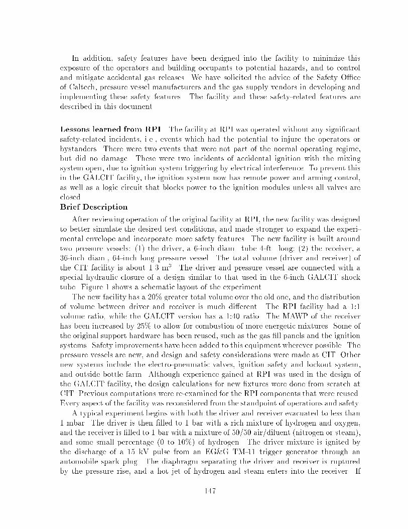
In addition� safety features have been designed into the facility to minimize thisexposure of the operators and building occupants to potential hazards� and to controland mitigate accidental gas releases� We have solicited the advice of the Safety O�ceof Caltech� pressure vessel manufacturers and the gas supply vendors in developing andimplementing these safety features� The facility and these safetyrelated features aredescribed in this document�
Lessons learned from RPI The facility at RPI was operated without any signi�cantsafetyrelated incidents� i�e�� events which had the potential to injure the operators orbystanders� There were two events that were not part of the normal operating regime�but did no damage� These were two incidents of accidental ignition with the mixingsystem open� due to ignition system triggering by electrical interference� To prevent thisin the GALCIT facility� the ignition system now has remote power and arming control�as well as a logic circuit that blocks power to the ignition modules unless all valves areclosed�Brief Description
After reviewing operation of the original facility at RPI� the new facility was designedto better simulate the desired test conditions� and made stronger to expand the experimental envelope and incorporate more safety features� The new facility is built aroundtwo pressure vessels� �� the driver� a �inch diam� tube �ft� long� �� the receiver� a��inch diam�� ��inch long pressure vessel� The total volume driver and receiver� ofthe CIT facility is about ��� m�� The driver and pressure vessel are connected with aspecial hydraulic closure of a design similar to that used in the �inch GALCIT shocktube� Figure � shows a schematic layout of the experiment�
The new facility has a � � greater total volume over the old one� and the distributionof volume between driver and receiver is much di�erent� The RPI facility had a ���volume ratio� while the GALCIT version has a ��� ratio� The MAWP of the receiverhas been increased by ��� to allow for combustion of more energetic mixtures� Some ofthe original support hardware has been reused� such as the gas �ll panels and the ignitionsystems� Safety improvements have been added to this equipment wherever possible� Thepressure vessels are new� and design and safety considerations were made at CIT� Othernew systems include the electropneumatic valves� ignition safety and lockout system�and outside bottle farm� Although experience gained at RPI was used in the design ofthe GALCIT facility� the design calculations for new �xtures were done from scratch atCIT� Previous computations were reexamined for the RPI components that were reused�Every aspect of the facility was reconsidered from the standpoint of operations and safety�
A typical experiment begins with both the driver and receiver evacuated to less than� mbar� The driver is then �lled to � bar with a rich mixture of hydrogen and oxygen�and the receiver is �lled to � bar with a mixture of � �� air�diluent nitrogen or steam��and some small percentage to � �� of hydrogen� The driver mixture is ignited bythe discharge of a �� kV pulse from an EG�G TM�� trigger generator through anautomobile spark plug� The diaphragm separating the driver and receiver is rupturedby the pressure rise� and a hot jet of hydrogen and steam enters into the receiver� If
���
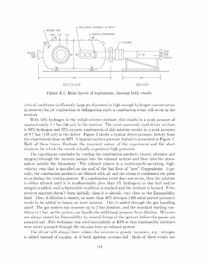
Figure A��� Basic layout of experiment� showing both vessels�
critical conditions su�ciently large jet diameter�or high enough hydrogen concentrationin receiver� for jet combustion or de�agration exist� a combustion event will occur in thereceiver�
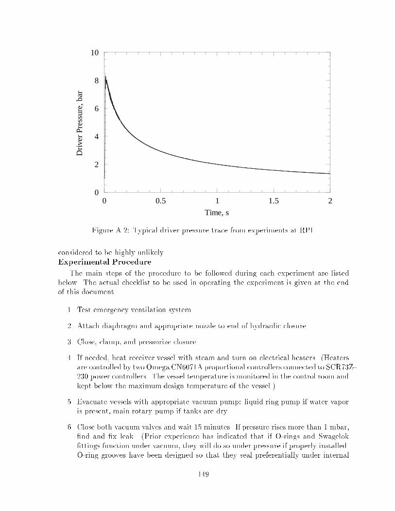
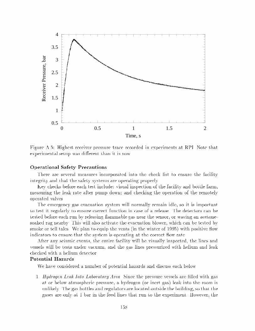
With � � hydrogen in the initial receiver mixture� this results in a peak pressure ofapproximately ��� bar � psi� in the receiver� The most commonly used driver mixtureis � � hydrogen and � � oxygen� combustion of this mixture results in a peak pressureof ��� bar �� psi� in the driver� Figure � shows a typical driver pressure history fromthe experiments done at RPI� A typical receiver pressure history is presented in Figure ��Both of these traces illustrate the transient nature of the experiment and the shortduration for which the vessels actually experience high pressures�
The experiment concludes by venting the combustion products water� nitrogen andoxygen� through the vacuum pumps into the exhaust system and then into the atmosphere outside the laboratory� The exhaust system is a continuouslyoperating� highvelocity vent that is installed on the roof of the �nd �oor of �new� Guggenheim� Typically� the combustion products are diluted with air and the steam is condensed out priorto or during the venting process� If a combustion event does not occur� then the mixtureis either diluted until it is non�ammable less than �� hydrogen� or else fuel and�oroxygen is added until a �ammable condition is reached and the mixture is burned� If thereceiver mixture doesn�t burn initially� then it is already very close to the �ammabilitylimit� Thus� if dilution is chosen� no more than � � nitrogen � mbar partial pressure�needs to be added to insure an inert mixture� This is added through the gas handlingpanel� The gas system can measure up to � bar absolute� and the standard starting condition is � bar� so the system can handle the additional pressure from dilution� Mixturesare always tested for �ammability by several �rings of the ignitors before the gasses arepumped out� This technique was used successfully at RPI so that combustible mixtureswere never pumped through the vacuum lines or exhaust system�
The driver will always burn unless the mixture is grossly incorrect� e�g�� nitrogenis added instead of oxygen� or if both ignition systems fail� Both of these events are
���
0
2
4
6
8
10
0 0.5 1 1.5 2
Dri
ver
Pres
sure
, bar
Time, s
Figure A��� Typical driver pressure trace from experiments at RPI�
considered to be highly unlikely�Experimental Procedure
The main steps of the procedure to be followed during each experiment are listedbelow� The actual checklist to be used in operating the experiment is given at the endof this document�
�� Test emergency ventilation system�
�� Attach diaphragm and appropriate nozzle to end of hydraulic closure�
�� Close� clamp� and pressurize closure�
�� If needed� heat receiver vessel with steam and turn on electrical heaters� Heatersare controlled by two Omega CN� ��A proportional controllers connected to SCR��Z�� power controllers� The vessel temperature is monitored in the control room andkept below the maximum design temperature of the vessel��
�� Evacuate vessels with appropriate vacuum pump� liquid ring pump if water vaporis present� main rotary pump if tanks are dry�
�� Close both vacuum valves and wait �� minutes� If pressure rises more than � mbar��nd and �x leak� Prior experience has indicated that if Orings and Swagelok�ttings function under vacuum� they will do so under pressure if properly installed�Oring grooves have been designed so that they seal preferentially under internal
���
pressure� Moreover� the system has been hydrotested and helium leak tested underpressure��
�� Open gas feed valve on receiver� and isolation valves � and � on driver�
�� Fill both vessels with desired mixtures using method of partial pressures� Monitorpressure gauges for leakage� Close receiver gas feed valve�
�� Run mixers for ten minutes�
� � Close driver isolation valves� and ensure that all other valves are closed�
��� Run data acquisition software� entering appropriate data on screen�
��� Turn on master ignition power key switch� Arm and �re driver when ready�
��� Save data� and safe �ring system�
��� Open receiver gas feed and driver isolation valves� Add enough air�oxygen to burnremaining hydrogen� Follow mixing and �ring procedure from above� without dataacquisition�
��� Evacuate water vapor with liquid ring pump� or vent tank up to atmospheric pressure with air� depressurize closure� and separate tanks�
Design Considerations
The design considerations and safety related features of the key components of thefacility are described below�Compressed Gas Supply Design
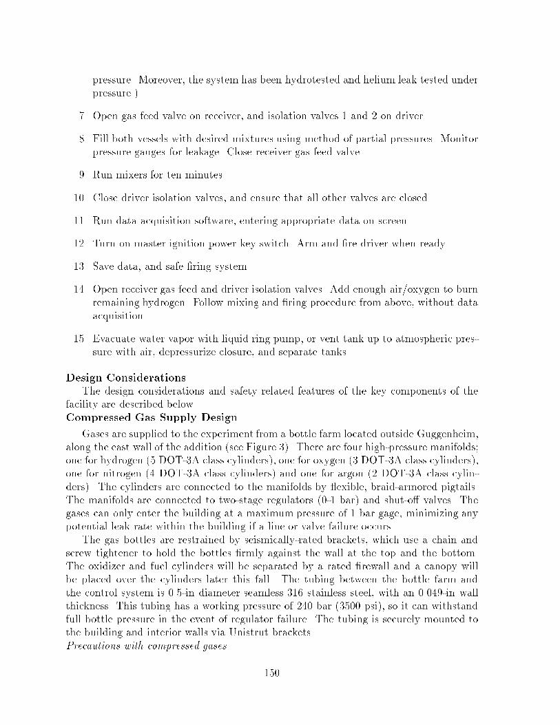
Gases are supplied to the experiment from a bottle farm located outside Guggenheim�along the east wall of the addition see Figure ��� There are four highpressure manifolds�one for hydrogen � DOT�A class cylinders�� one for oxygen � DOT�A class cylinders��one for nitrogen � DOT�A class cylinders� and one for argon � DOT�A class cylinders�� The cylinders are connected to the manifolds by �exible� braidarmored pigtails�The manifolds are connected to twostage regulators � bar� and shuto� valves� Thegases can only enter the building at a maximum pressure of � bar gage� minimizing anypotential leak rate within the building if a line or valve failure occurs�
The gas bottles are restrained by seismicallyrated brackets� which use a chain andscrew tightener to hold the bottles �rmly against the wall at the top and the bottom�The oxidizer and fuel cylinders will be separated by a rated �rewall and a canopy willbe placed over the cylinders later this fall� The tubing between the bottle farm andthe control system is ��in diameter seamless ��� stainless steel� with an � ��in wallthickness� This tubing has a working pressure of �� bar �� psi�� so it can withstandfull bottle pressure in the event of regulator failure� The tubing is securely mounted tothe building and interior walls via Unistrut brackets�Precautions with compressed gases
��
Figure A��� Floor plan of the Explosion Dynamics Laboratory� �����A Guggenheim andbottle farm outside on the upper level�
���

The gases used in this experiment are argon� nitrogen� oxygen� and hydrogen� Thereare obvious potential hazards CGA ��� � when using such gases in a con�ned space suchas our laboratory� The amount of gas present in the lab is minimized by locating the highpressure gas outside of the building� and by not using any secondary mixing reservoirs�There are three types of potential hazards that we have speci�cally considered�
�� Su�ocation nitrogen� argon and hydrogen��
The argon and nitrogen are inert� and could be a hazard through displacement ofoxygen in the lab� This would be di�cult to detect� but unlikely� since fresh air iscontinually forced into the lab via the building HVAC system� Should the HVACor emergency purge systems fail� the experiment will not be continued� Failure ofthese systems would likely be due to a general electrical power outage� which wouldclose the valves and isolate the vessels� Manual gas supply closure would follow�
�� Increased �re hazard oxygen��
Enriched oxygen in the lab atmosphere would enhance �ammability of items in thelab� This threat will also be reduced by the in�ux of fresh air from the buildingHVAC system�
�� Explosion hazard hydrogen��
The hydrogen gas is the main cause for concern� due to its �ammability� Hydrogen iscombustible between � and � � by volume in air� A number of design and operationalprocedures have been included to minimize the potential hazard� These are�
�� All plumbing is heavy wall stainless steel with Swageloktype �ttings�
�� Pressure and quantities of gas within the building are minimized�
�� The gas supply lines are shut o� externally at the bottle farm level� when not inuse and internally at the gas supply panel at all other times except when �lling withthat gas� At the bottle farm� the gas is shut o� via a valve between the manifoldand the regulator� If the system will be down for an extended period� the bottlevalves will be closed as well� In the lab� the procedure is to have all gas supply andmetering valves closed except when in use�
�� Plumbing system is pressurized and leaktested using a helium leak detector purchased speci�cally for that purpose�
�� The laboratory is equipped with an emergency air ventilation system�
This system provides for an intake of � cfm from the makeup air system and theexhaust of a somewhat larger � cfm� amount through a highvelocity exhaust fanmounted on the roof of �new� Guggenheim� The exhaust motor and fan assemblyare of explosion proof construction�
���

The four ceiling intakes for this exhaust system are directly over the gas supplycontrol panels� the driver tube� and the other explosion vessel located in the experimental area see Figure ��� The vents are located at �highpoints� in the ceilings�The ceilings are designed with a slope toward these points and are sealed exceptfor some minor penetrations� the air intakes and the emergency exhaust systems�In case of a major leak into the region above the ceiling� there are three exhaustvents � cfm each� located within the space between the ceiling and the concrete�oor� This ceiling space is separated between the experimental and control areas�Two of the vents are located in the experimental area and one in the control area�In the case of the experimental area� the ceiling is taped wallboard� in the case ofthe control room� the ceiling is liftout acoustical tiles with seals� These acousticaltiles are sealed with a plastic coating to reduce gas penetration� The vent systemis either actuated automatically due to gas detection or manually by a switch inthe control room�
�� The hydrogen supply is equipped with an emergency shuto� valve�
A electropneumatic valve is located in the hydrogen supply line outside of building�� This valve is opened by remote control only when gas is needed for theexperiment� At all other times� it shall be closed� The valve requires both electrical power and air pressure to operate� if one of these is lost due to an accident i�e��earthquake�� the valve will automatically close� The valve is rated to ��� bar� so itcan withstand full bottle pressure if the regulator fails�
�� The laboratory is equipped with a �ammable gas detection system that is interlocked to the gas supply and the ventilation system�
There are two �ammable gas detectors Sierra Monitors model � �� that willactuate when hydrogen is detected at the � ppm level a factor of � below the�ammability limit�� The shuto� valve described above will be closed automaticallyif either of the detectors are actuated� At the same time� a warning light and anaudible alarm is sounded and the emergency venting system is actuated� Thedetector locations are shown in Figure �� Further description of this system isprovided below�
�� The only exhaust system from the test vessel or the supply system is through acontinuouslyoperated highvelocity vent to the exterior of the building�
�� The operators are physically separated from the test vessels by a wall covered witha steel shrapnel barrier see Figure ��� The experiment is remotely operated by amimic panel using electropneumatic valves�
When the facility is not in use� it is left either under vacuum or at atmosphericpressure� There is no provision for purging the supply lines� as these gasses are nonreactive with stainless steel under these conditions� To prevent contamination� the gassupply lines are closed and left at or above ambient pressure �� psig� when not in use�
���
Figure A��� Gas Supply system for the Hydrogen Jet Combustion Facility�
���
Driver Design Considerations
The design load for the driver is a detonation of a stoichiometric mixture of hydrogenand oxygen� The CJ pressure for this mixture is �� bar initial conditions of � bar and� K� and the peak re�ected pressure is �� bar� Allowing for the maximum dynamicload factor of � Shepherd ������ the equivalent maximum average working pressure thevessel should be designed for is � bar� This factor of � is the upper bound of the responseof an undamped elastic system to a step load� It is a general result� not speci�c to anygeometry Biggs ������ and used in both the driver and receiver design� In addition topressure considerations� the driver should be designed from a ductile material with a highultimate strength in order to accommodate any potential pressure transients that mightresult from DDT events�
The driver is constructed of a fourfoot length of sixinchdiameter� seamless stainlesssteel ���� tubing with a halfinch wall thickness� Stainless steel ���� �anges �� inchthick and ��inch diameter are welded to each end of the tubing� Eight ���inch SAEgrade � bolts are used to connect the �anges to the end plate and the closure assembly�Using an allowable stress of ���� kpsi� the corresponding hoop stress would limit themaximum allowable working pressure to ��� psi ��� bar��
The end �anges are doublewelded� and are estimated using the allowable stress� totake a pressure load of �� bar� The bolts retaining the blind �ange are ���in grade�� and capable of retaining the end �ange under a pressure of nearly �� bar� so evenwith preload they will be able to readily withstand ��� bar� The plumbing �ttings areall � lb class� and the connecting nipples are schedule � stainless steel� These arethe same �ttings that were used on the RPI apparatus�
Derating this for the stress concentrations at the penetrations� we conclude that themaximumworking pressure of this assembly is at least � bar� Since the allowable stressused in making this computation includes a substantial factor of safety already� thisdesign can safety accommodate the design load without any safety implications�
Hydrogen embrittlement may be an issue when pressure vessels are used with hydrogen� Three conditions Harvey ����� Nelson ����� are required for hydrogen embrittlement to occur�
�� A high hardness microstructure�
�� Penetration of hydrogen into the metal orpreexisting hydrogen within the metal�
�� Stress� either residual or imposed�
None of these conditions exist in the driver� In general� hydrogen embrittlement intype ��� stainless is never a problem Harvey ����� unless the material is used at veryhigh temperatures to contain hydrogen at high pressures greater than � bar�� Datafrom the U�S� Air Force Metals Handbooks indicate that � � SS only su�ers a �� loss instrength when exposed to pure hydrogen at ��� bar for �� hours�
Type ��� stainless steel has a low hardness microstructure and is formulated to resiststress corrosion by hydrogen� There will be extremely limited penetration of hydrogen
���
in the vessel due to low pressures and temperatures in comparison to typical hydrogenembrittlement conditions� For most of the test� the hydrogen and the vessel will be atroom temperature and the hydrogen partial pressure will be less than one atmosphere�After ignition� the pressure and temperature rise to their peak values within milliseconds� but heat transfer to the tube walls cools the gas rapidly and the pressure reachessubatmospheric values within � to � seconds� as shown in the driver pressure plot� Theburn also reduces the hydrogen concentration to � ��
Cumulative exposure is not considered to be a problem with this facility� as thehydrogen embrittlement process requires a threshold in pressuretemperature conditionsbefore it will even occur� This threshold is not approached in this facility� Both the driverand receiver vessels were designed for hydrogen service� Per the references stated above�there are no restrictions on the lifetime of the vessel for our pressuretime history� Thepressure exceeds one bar for approximately � seconds per test� and at � tests per year�this yields about � minutes of cumulative operation with a hydrogen partial pressure of� to � bar at most�
The facility is expected to be used for at least � years� For this duration� fatiguelife will not be an issue for this facility� At � tests per year� this yields a total of � cycles which places the facility in the low cycle regime of fatigue Shigley ��� �� In thisregime� the fatigue strength approaches the tensile strength� Since the facility designincorporates a substantial safety factor four in the receiver design�� the operationalstresses are substantially lower than the fatigue limit� Fatigue failure of the componentsis thus not an issue for the projected lifetime� If the maximumstress incurred in operationis less than the endurance limit typically onehalf of the tensile strength for carbon andalloy steels�� the lifetime is e�ectively in�nite� This is most likely the case in our facility�
Closure Design Considerations
A specialized closure assembly design originally developed at GALCIT for the �inchshock tube is used to connect the driver to the receiver� This closure is made of forgedstainless steel � � and � �� components and a forged steel � � � clamp ring that carriesthe load� Estimates of the axial stress and stress produced by the moment load on theclamp indicate that the performance will be within the allowable stress even with apressure as high as ��� bar � psi� within the driver section� Radial loads are carriedby the main structure of the closure� which is hydraulically sealed when in operation�The hydraulic action provides an axial clamping force of �� � lbs on the diaphragm�This closure was successfully used in the previous experiment at RPI�
After the closure was partially modi�ed and installed on the GALCIT facility� itwas hydrotested insitu with the driver at �� psi� Preshot checkout includes visualinspection of seals� Orings� closure position� and for hydraulic �uid leaks� When theclosure is pressurized� a gage on the pump indicates hydraulic pressure� This gage alsohas a pressure switch� which is connected to the �ring interlock� If the pressure dropsbelow � psi� the �ring system will be locked out� and the green light on the controlpanel will extinguish�Receiver Design Considerations
Conditions in the receiver vessel are generally much more benign than in the driver�
���
However� it has been designed to withstand higher pressures than before� In the worstcase� we would have a detonation in stoichiometric hydrogenair at one atmosphere initialpressure� The equivalent pressure produced by a re�ected wave with a dynamic loadfactor of two is �� bar� The vessel is designed for a maximum average working pressureof ���� �� psi� bar� and was hydrotested to �� bar �� psi�� In most cases� the vesselwill be �lled with more dilute mixtures� and operated at higher initial temperatures� sothat the re�ected and compensated pressure will not exceed �� bar� The highest pressuregenerated in the receiver in the RPI experiments was about � bar Figure ���
The receiver is a mild carbon steel ASTM A���� � pressure vessel �� inches indiameter� �� inches seamtoseam� There are four � lb class nozzles and �anges weldedto the tank and a number of smaller penetrations� All �ange closures are also rated to� lb class and are attached with grade � ASTM A���� fasteners� A specially designed�ange is used to attach �inch diameter windows to each side of the test section� Thesewindows are used for �ow visualization of the jet and combustion events within thereceiver� There are three axial window locations but only one of these is used at a time�The others are �lled with steel blanks when not in use�
The vessel was built and certi�ed to the standards of Section VIII of the ASMEBoiler and Pressure Vessel Code� This includes a full Xray inspection of all welds� and acorrosion allowance of � ��� inches� The preliminary design of the vessel� including sizeand location of �anges and ports� was done at Caltech� Final design and material selectionand sizing was done by R� L� Morton Welding Inc�� Valley Acres� CA� fabricator of thevessel� All of the materials used in the tank were accompanied by mill reports on chemicalcomposition� yield strength and elongation testing� Discussions with the metallurgist atR� L� Morton identi�ed fracture toughness as being a material issue for an explosive testvessel� This is one of the key reasons for the material choice� To insure material quality�material samples were also impact tested for toughness� The Charpy impact tests werecarried out at � and � degrees Fahrenheit� and the material specimens required atleast twice the minimum allowable energy to fracture� The �nal report on the vesselfabrication and the material certi�cations is available on �le in ��A Guggenheim�
The design pressure MAWP� of the tank is �� psi at �� �F� The pressure was chosenon the basis of the calculated peak pressures in the event of a hydrogenair detonationwithin the receiver� Previous tests have all been with de�agrations and the observedpeak pressure has always been less than � bar � psi� in the receiver� The vessels usedat RPI had a design pressure of � psi� and the peak pressure measured in the driverwas � bar ��� psi��
This was a case with a very large ori�ce between the two tanks� and the identicalsize of the two vessels caused a high level of pressurization in the receiver� If an overpressure event does occur that exceeds the hydrotest rating of the vessel� then it will bemechanically inspected and retested if necessary�
Hydrogen embrittlement is not an issue in this vessel either� None of the key factorsmentioned above are satis�ed for the receiver vessel� Tests Nelson ����� with mild carbonsteel vessels indicate that embrittlement does not occur at hydrogen partial pressures lessthan �� psi when the vessel temperature is less than � �F�
���
0.5
1
1.5
2
2.5
3
3.5
4
0 0.5 1 1.5 2
Rec
eive
r Pr
essu
re, b
ar
Time, s
Figure A��� Highest receiver pressure trace recorded in experiments at RPI� Note thatexperimental setup was di�erent than it is now�
Operational Safety Precautions
There are several measures incorporated into the check list to ensure the facilityintegrity and that the safety systems are operating properly�
Key checks before each test include� visual inspection of the facility and bottle farm�measuring the leak rate after pump down� and checking the operation of the remotelyoperated valves�
The emergency gas evacuation system will normally remain idle� so it is importantto test it regularly to ensure correct function in case of a release� The detectors can betested before each run by releasing �ammable gas near the sensor� or waving an acetonesoaked rag nearby� This will also activate the evacuation blower� which can be tested bysmoke or tell tales� We plan to equip the vents in the winter of ����� with positive �owindicators to ensure that the system is operating at the correct �ow rate�
After any seismic events� the entire facility will be visually inspected� the lines andvessels will be tests under vacuum� and the gas lines pressurized with helium and leakchecked with a helium detector�Potential Hazards
We have considered a number of potential hazards and discuss each below�
�� Hydrogen Leak Into Laboratory Area� Since the pressure vessels are �lled with gasat or below atmospheric pressure� a hydrogen or inert gas� leak into the room isunlikely� The gas bottles and regulators are located outside the building� so that thegases are only at � bar in the feed lines that run to the experiment� However� the
���

possibility exists that an open valve� a leak in one of the pressure vessel connections�or a leak in one of the Swagelok �ttings could release hydrogen into the laboratoryenvironment� To protect against this� we have hydrogen � combustible gas detectorsstrategically located in each room SMC model � �� � calibrated to activate at� ppm hydrogen�� In the control room� the detector is located above the gaspanels� the only source of hydrogen in that room see Figure ��� The ceiling inthat room is sloped upward towards the detector� as the hydrogen gas will rise andseek the highest point in the room� In the experiment area� the ceiling is slopedupwards to an inverted �trough� over the experiment� This trough contains anothercombustible gas detector and intakes for the hydrogen exhaust system�
If the detector goes into alarm mode� it activates a latching relay which has severalfunctions� First� it activates a warning light and buzzer in the lab� Second� itshuts o� the hydrogen supply valve at the bottle farm� preventing further hydrogenfrom entering the lab� Third� it is connected to the ventilation system to turn o�the air handler and turn on the evacuation system this is a �� cfm exhaust fanlocated on the roof�� This system can not be reset until the detector returns to�safe� mode� There is no way to turn o� the detector system unless the power isremoved� This would then remove power from the supply valve� stopping the gassupply anyway�
Another situation that could introduce hydrogen into the lab area would be accidental� manual opening of the tanks when they are �lled with a combustiblemixture and if they were pressurized to greater than atmospheric pressures� Normal operation is to only pressurize the tanks to � bar absolute� initial pressureprior to the test� Therefore in normal operating conditions� opening the vessels tothe atmosphere would not constiute a hazard unless the gas supply system was lefton�
However� it is possible for the operator to �ll the tanks to higher pressures andexcessive hydrogen concentrations since the supply manifolds operate at pressureof � bar gauge� This would require gross negligence on the part of the operatorsince the valves used to introduce and control the �ow rates of the various gases aremanually operated� To reduce the possibility of such negligence� we plan to modifythe facility to require continuous operator action holding down a push button�in order to �ll with hydrogen gas� This requirement will force the operator to bephysically at the control panel and able to monitor the pressure at all times duringthe �ll process�
A typical experimental condition would be � � hydrogen in the receiver� and � �hydrogen in the driver� The volume of the receiver is ��� cubic meters� and thatof the driver is � �� cu m� These fractions would yield a total volume of ���cu m of hydrogen at atmospheric pressure� The volume of the room is �� cu m�so the fraction of hydrogen in the room would only be ���� Since �� hydrogenis required to have any type of combustion at all� this would be a non�ammablemixture� It is possible for �ammable concentrations of hydrogen to exist locally�
���
but the HVAC circulation and hydrogen buoyancy would quickly disperse and mixthese local concentrations�
�� Vessel Breach Due To Overpressure� The peak pressure that could occur in thissystem is �� bar� based on a re�ected detonation of a stoichiometric mixture ofhydrogen and oxygen including a factor of � for dynamic loading�� The tank isdesigned to withstand ���� bar� and ASME code incorporates a substantial factorsafety is determining the allowable stress� In the case of the receiver� the allowablestress used in the design is ��� of the ultimate tensile strength of the material� Thewelds and penetrations have been designed with a similar factor of safety in thisvessel resulting in an ultimate capacity of about � bar� Thus� we have a safetyfactor of � for the worst possible case� We conclude that catastrophic failure of thisvessel is not a credible failure mode�
However� as discussed below� the windows or other secondary components may failunder extreme loads� As additional protection� the walls of the experimental areaare lined with ���in steel plate to protect the surroundings from any fragmentsthat may be ejected from the tank� These could include transducers� igniter plugs�or window fragments� Note that the �� bar pressure quoted above can not beobtained within the present operating envelope� This value is used to provide anextreme upper bound on the maximum pressure that might be encountered underabnormal conditions� As mentioned earlier� the highest pressures encountered atRPI were � bar� We have considered the strength of the transducer and ignitormounts� and determined that these will not fail even at the �� bar level� Theforce on the transducer will only be �� lbs� and that on the spark plug will be ���lbs� These loads produce acceptable stress levels� Therefore� only the windows aresubject to failure at �� bar� These are discussed in the next section�
The ���inch steel wall will provide useful protection from glass and small metalfragments� Peak fragment velocities are di�cult to estimate� but a useful rule ofthumb is that the upper limit will be the sound speed in the emerging gas� whichwill be between � and � m�s� Typically� much lower velocities are obtainedfrom ruptured or bursting vessels due to the inertia of fragments and rapid decreasein gas velocity in the jet �ow outside the vessel� It is possible to get higher valuesin an underexpanded jet� Using the estimation techniques discussed in Baker etal� ���� a ����thick � � CRS plate will withstand � m�s normal impact�� Thepenetration velocity varies inversely with particle size and density so that smaller�higher velocity fragments would also be stopped�
�� Schlieren Window Failure Due To Overpressure� The �� mm dia� by �� mm thickwindows used for the schlieren can withstand a pressure of ���� bar� much greaterthan the typical pressures of � bar� This estimate was calculated from elastic theoryfor a simplysupported circular plate� The key parameter in this calculation is themaximum tensile strength of the window material BK��� Unlike most materials�there are no reliable values of yield strength for glass� as it depends strongly onthe surface condition and mounting technique� A value of � ksi was used in the
��
maximum pressure calculation� based on a range of values given by Melles Griot�Glass suppliers commonly quote values up to � ksi� We have exposed glass disksof similar aspect ratio to detonation waves resulting in stresses up to twice thisvalue without failure�
In this facility� if a detonation occurs� the peak pressure may exceed the estimatedload capacity of the windows� resulting in window failure� As mentioned in item��� operators and bystanders are protected from this by controlling the experimentfrom a separate room� and the steel plate on the walls surrounding the apparatus�In addition� the boxes containing the schlieren system will always be in front of thewindows� and will help to contain any glass fragments that may be produced�
To eliminate the possibility of window failure� we will only operate the facilitywith less than � � hydrogen in air� a re�ected detonation in this mixture wouldresult in acceptable peak pressures� If we go to richer mixtures� the window framescan be modi�ed to accept ���inch thick windows� which would increase the failurepressure by a factor of about ����� Additional failure protection could be providedby a ��� inch thick aluminum plate on the schlieren system opposite the windows�
Failure of the windows could also result in a blast wave� but it is di�cult to makean accurate estimate of its strength� The source term is highly transient and analogous to the muzzle blast from a gun� The e�ective driving pressure will be timedependent but will initially be much closer to the constantvolume explosion pressure� about � bar for stoichiometric hydrogenair� than the detonation pressure�With the above precautions� we consider window failure to be a highly unlikelyevent� If the operating envelope is enlarged to include nearstoichiometric hydrogen concentrations� then an appropriate blast and consequence analysis will beconsidered�
�� Mis�re� A mis�re occurs when there is a combustible mixture in either vesseland the ignition system fails to ignite it� This can occur if the electrodes on thespark plugs become fouled or there is an electrical system failure� If the amount ofhydrogen in the system is small enough� the mixtures can be inerted by addition ofnitrogen� and then pumped out of the vessels� Or� extra oxygen or hydrogen canbe added to sensitize the mixture� and the glow plugs can be used to ignite it�
�� Mixture Ignition With Containment Valves Open� All of the valves on the driverand receiver vessels are remotely operated with positive indication of the valveposition in the control room� The ignition system is interlocked with the valveindicator switches so that ignition can not occur unless the valves are closed�
If an accidental mixture ignition occurs with the gas supply � tank containmentvalves open� a pressure wave will travel through the gas supply tubing� This pressure will not exceed the � bar mentioned in item ��� and all of the plumbingcan safely handle this pressure� The tubing components have a minimum pressurerating of ��� bar� and the weakest valve in the system can withstand � � bar�
���
The only weak point in the system is the Heise gage located on each gas supplypanel� These are only rated for � bar and will be damaged if overpressurized� Thegages are quite robust� constructed with a heavy� cast metal body and blowoutbacks� The manufacturer does not have data on failure pressure available for thesegages� but from similar models� they suggest that the failure pressure would be atleast � � greater than full scale�
The gages have their own isolation valves which will be closed after the vessels are�lled with the proper mixtures� If the gage is pressurized to failure� the operatorwill be protected by a ���in thick sheet of Lexan mounted over the face of thegage� Lexan is a very tough material� which can withstand a large amount ofplastic deformation without fracturing� The gage faces are constructed of ��� inchPlexiglas� so the Lexan shields should be able to safely de�ect any fragments�
Failure of these gages would require multiple failures in the operating procedure�Two possible scenarios are� �� regulator fails� operator doesn�t follow checklist�opens supply and metering valves with vessel valve closed� and fails to take corrective action� �� Operator does not follow checklist� gage valve left open� vessel valvesopen� interlock system fails to function� and ignition occurs�
�� High Voltage Ignition System� Two TM��A high voltage trigger modules are usedto ignite the mixtures in the tanks� These modules generate a �� kV pulse� and thisvoltage is considered to be lethal regardless of the current supplied� The wiring forthese modules will be protected� and they are connected to AC power such thatthey can only be turned on from the control room� with a key�
�� Seismic Damage To Vessels� The vessels are both mounted on linear bearings whichallow them to translate in one direction� Safety brackets are mounted on these railsto prevent the vessels from jumping the track� Also� the gas lines connected to thetank are �exible� minimizing the possibility of damage or breakage�
�� Miscellaneous� In addition to the builtin safety devices� the laboratory also contains emergency equipment such as �re extinguishers� �rst aid kits� and personalprotective equipment safety glasses� dust masks� ear mu�s� etc�� to be used whileworking�
References
�� Baker et al� Explosion Hazards and Evaluation� Elsevier� �����
�� Biggs� J� M� Introduction to Structural Dynamics� McGrawHill �����
�� GGA ��� Handbook of Compressed Gases� Third Edition� Compressed GasAssociation� Inc�� Chapman and Hall� NY�
�� Harvey� J� F� ���� Theory and Design of Modern Pressure Vessels� VanNostrand Reinhold� NY�
���
�� Krok� J� C�� ����� Hydrogen Combustion Facility and Experiments� Master of Science Thesis� Rensselaer Polytechnic Institute� Troy� NY�
�� Nelson� G� A�� ����� �Metals for HighPressure Hydrogenation Plants�� Trans�ASME ��� � �����
�� Ross� M� C�� ����� Transient Jet Di�usion Flames in Hydrogen�Air�Nitrogen At�
mospheres� Master of Science Thesis� Rensselaer Polytechnic Institute� Troy� NY�
�� Shepherd� J� E�� ����� Pressure Loads and Structural Response of the BNL High
Temperature Detonation Tube� BNL Technical Report A����� Brookhaven National Laboratory�
�� Shigley� J� E� and Mischke� C� R� Mechanical Engineering Design� McGrawHill������
���

���

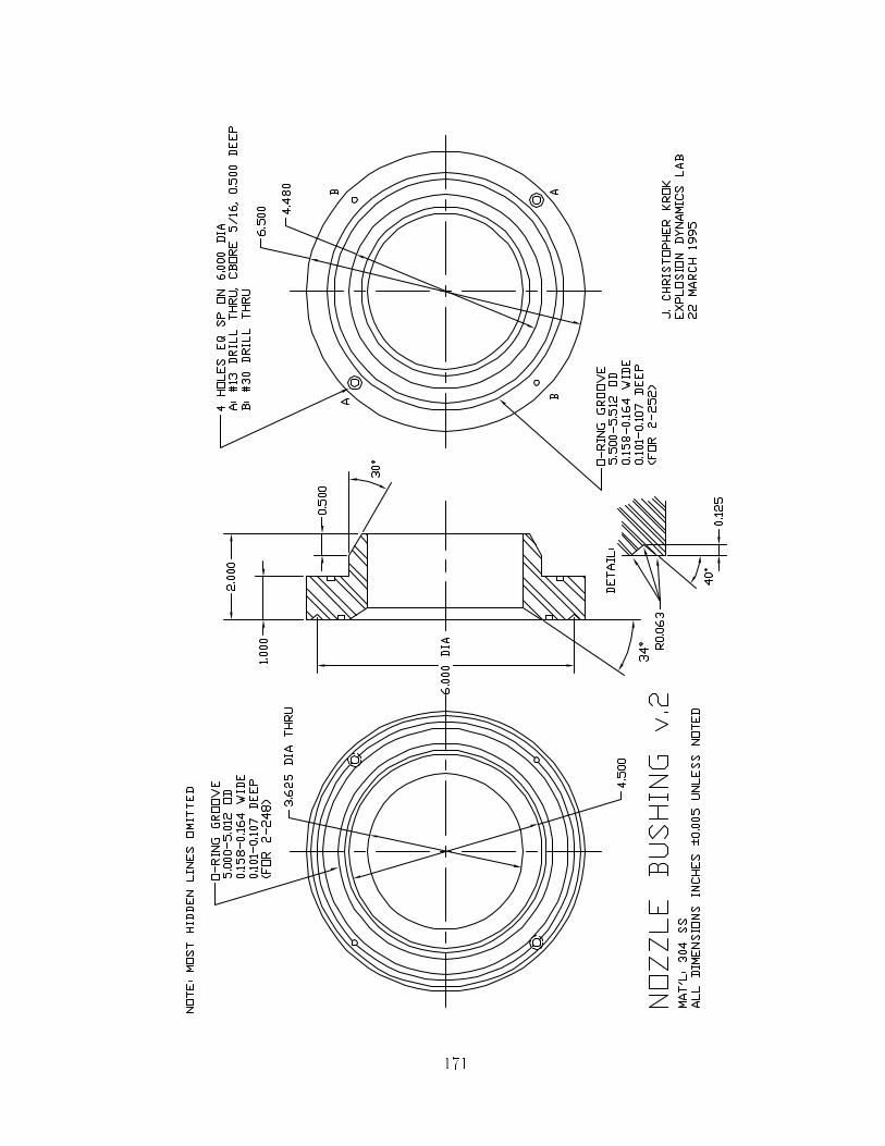
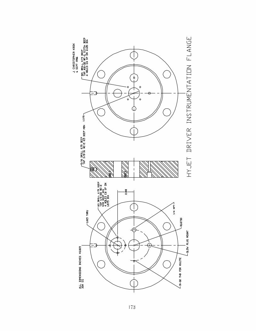
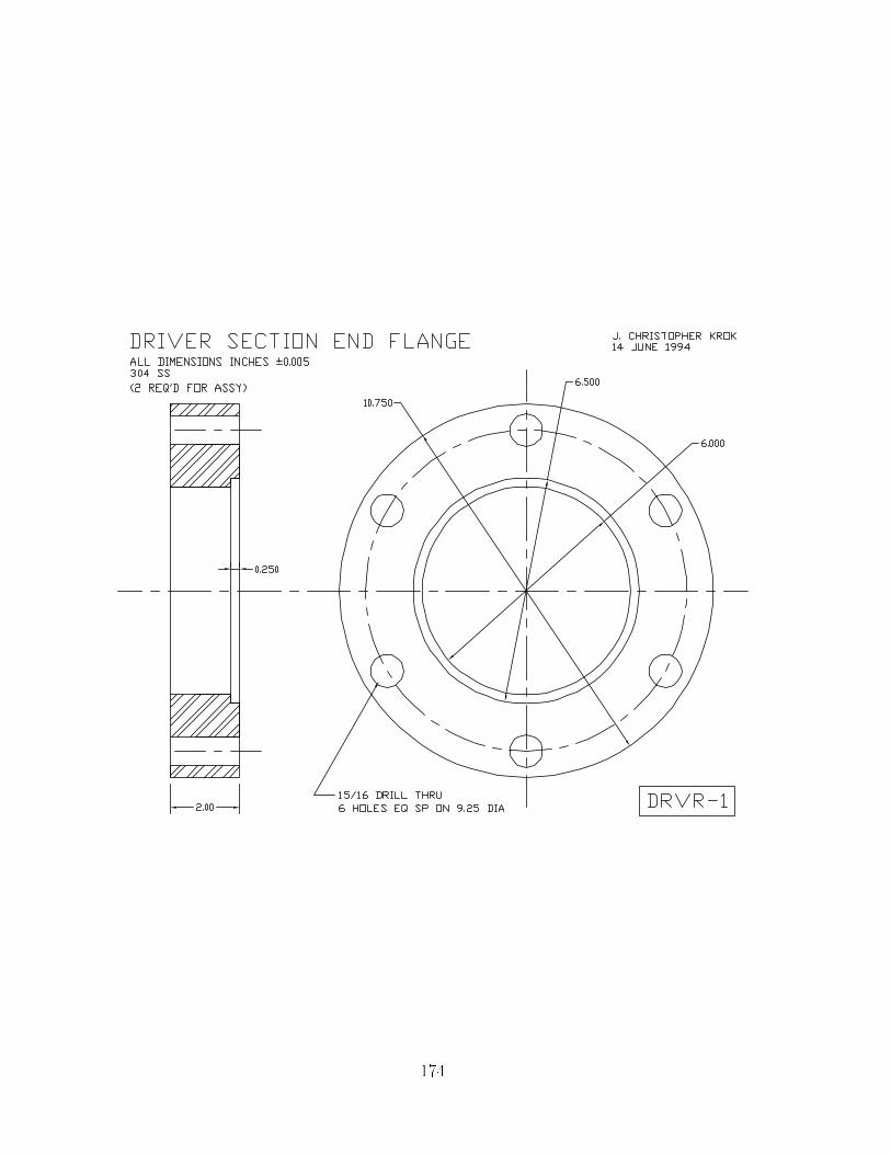
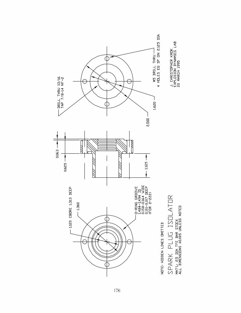
Appendix B
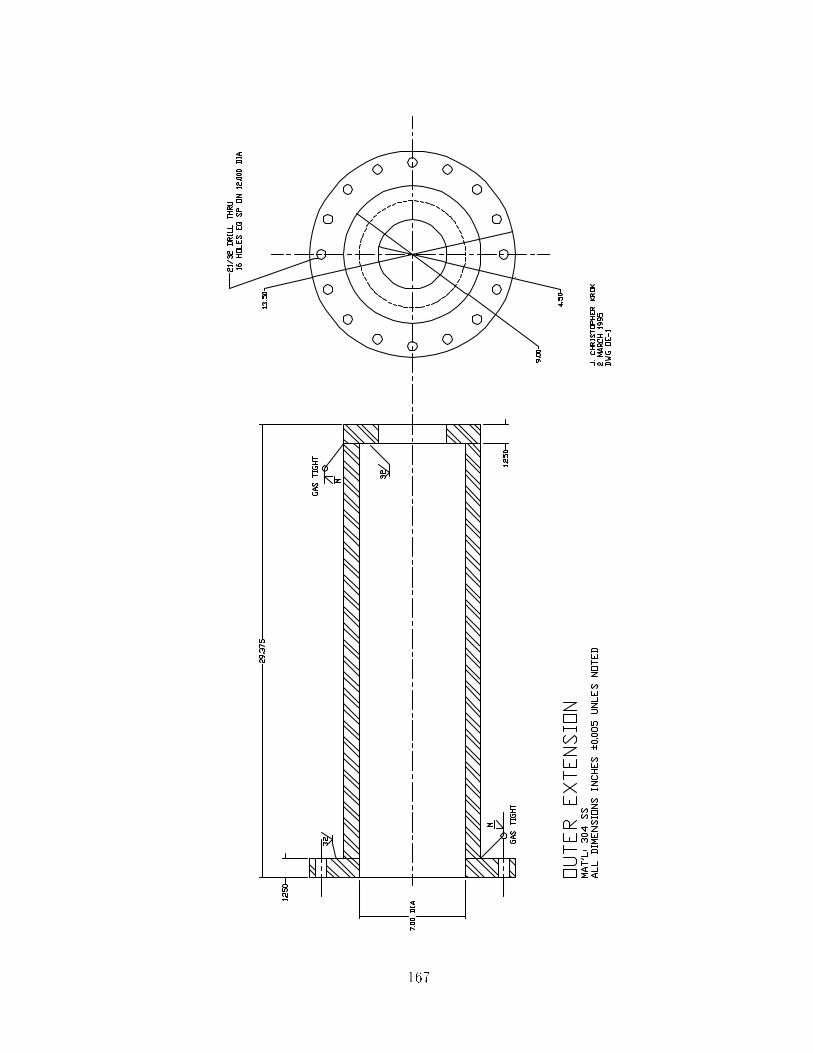
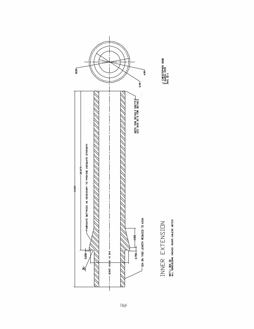
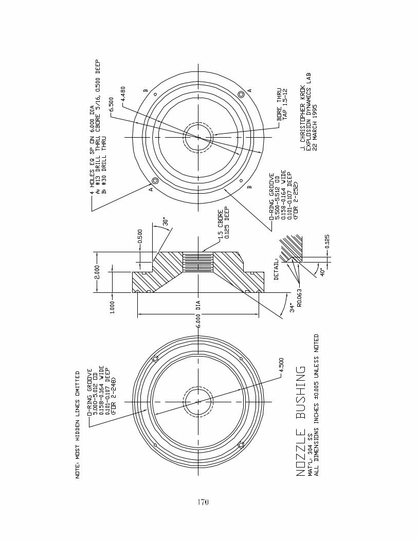
System Drawings
This appendix contains AUTOCAD drawings from the HYJET facility for reference
purposes�
���

���
���
���

���
��
���

��
���
���

���
���
���
���
���

��

Appendix C
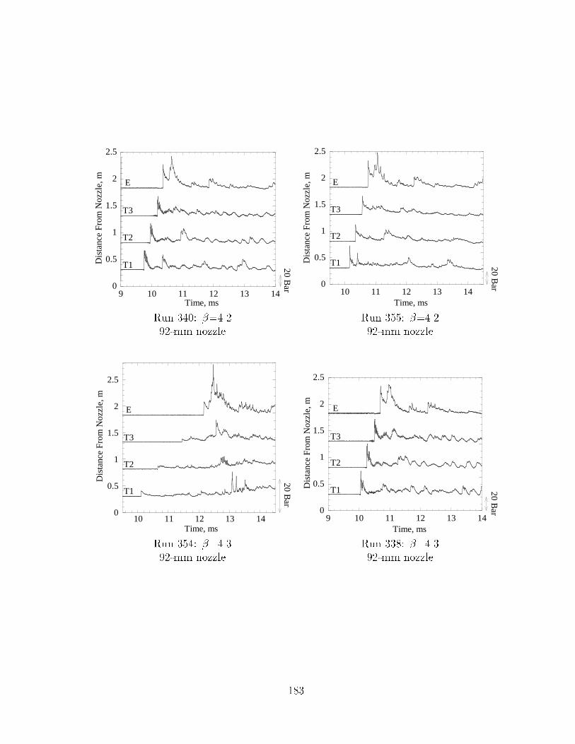
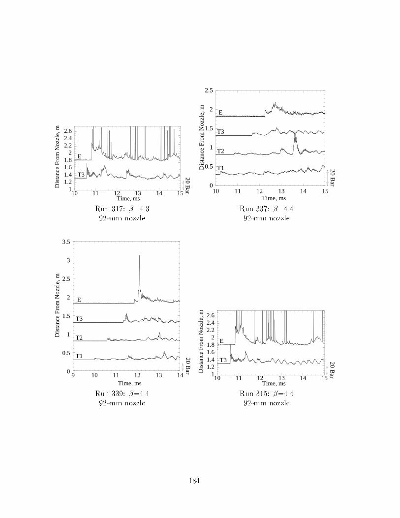
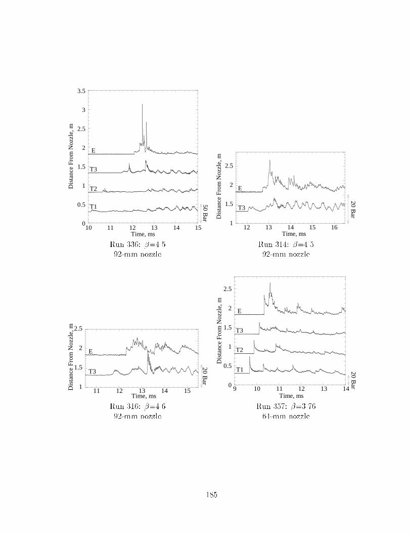
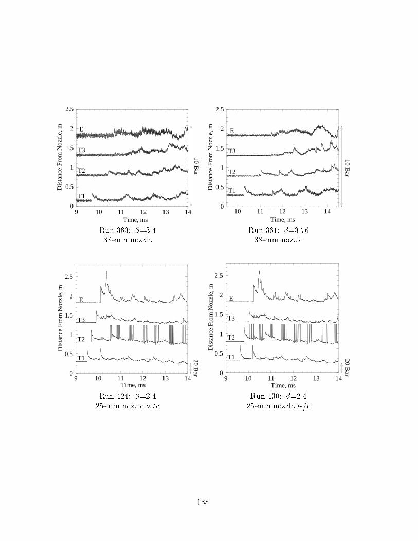
BETA Pressure Traces
This section contains plots of all pressure traces in the BETA series� They are organizedin order of increasing � for each system�
���
C�� Nitrogen Dilution� ��� K
0
0.5
1
1.5
2
2.5
9 10 11 12 13 14
Dis
tanc
e Fr
om N
ozzl
e, m
Time, ms
20 Bar
E
T3
T2
T1
0
0.5
1
1.5
2
2.5
9 10 11 12 13 14
Dis
tanc
e Fr
om N
ozzl
e, m
Time, ms
20 Bar
E
T3
T2
T1
Run ���� ��� Run ��� ���� mm nozzle � mm nozzle
11.21.41.61.8
22.22.42.6
10 11 12 13 14
Dis
tanc
e Fr
om N
ozzl
e, m
Time, ms
20 Bar
E
T3
11.21.41.61.8
22.22.42.6
10 11 12 13 14 15
Dis
tanc
e Fr
om N
ozzl
e, m
Time, ms
20 Bar
E
T3
Run ��� ����� Run ���� ���� mm nozzle � mm nozzle
��
0
0.5
1
1.5
2
2.5
9 10 11 12 13 14
Dis
tanc
e Fr
om N
ozzl
e, m
Time, ms
20 Bar
E
T3
T2
T1
0
0.5
1
1.5
2
2.5
10 11 12 13 14
Dis
tanc
e Fr
om N
ozzl
e, m
Time, ms
20 Bar
E
T3
T2
T1
Run ���� ���� Run ���� ����� mm nozzle � mm nozzle
0
0.5
1
1.5
2
2.5
10 11 12 13 14
Dis
tanc
e F
rom
Noz
zle,
m
Time, ms
20 Bar
E
T3
T2
T1
0
0.5
1
1.5
2
2.5
9 10 11 12 13 14
Dis
tanc
e Fr
om N
ozzl
e, m
Time, ms
E
T3
T2
T1 20 Bar
Run ���� ����� Run ���� ������ mm nozzle � mm nozzle
���
11.21.41.61.8
22.22.42.6
10 11 12 13 14 15
Dis
tanc
e Fr
om N
ozzl
e, m
Time, ms
E
T3 20 Bar
0
0.5
1
1.5
2
2.5
10 11 12 13 14 15
Dis
tanc
e Fr
om N
ozzl
e, m
Time, ms
20 Bar
E
T3
T2
T1
Run ���� ����� Run ���� ������ mm nozzle � mm nozzle
0
0.5
1
1.5
2
2.5
3
3.5
9 10 11 12 13 14
Dis
tanc
e Fr
om N
ozzl
e, m
Time, ms
E
T3
T2
T1 20 Bar
11.21.41.61.8
22.22.42.6
10 11 12 13 14 15
Dis
tanc
e Fr
om N
ozzl
e, m
Time, ms
20 Bar
E
T3
Run ���� ����� Run ���� ������ mm nozzle � mm nozzle
���
0
0.5
1
1.5
2
2.5
3
3.5
10 11 12 13 14 15
Dis
tanc
e Fr
om N
ozzl
e, m
Time, ms
50 Bar
E
T3
T2
T1
1
1.5
2
2.5
12 13 14 15 16D
ista
nce
From
Noz
zle,
m
Time, ms
20 Bar
E
T3
Run ��� ����� Run ���� ������ mm nozzle � mm nozzle
1
1.5
2
2.5
11 12 13 14 15Dis
tanc
e Fr
om N
ozzl
e, m
Time, ms
20 Bar
E
T3
0
0.5
1
1.5
2
2.5
9 10 11 12 13 14
Dis
tanc
e Fr
om N
ozzl
e, m
Time, ms
20 Bar
E
T3
T2
T1
Run ��� ���� Run ���� ������ mm nozzle � mm nozzle
���

0
0.5
1
1.5
2
2.5
9 10 11 12 13 14
Dis
tanc
e Fr
om N
ozzl
e, m
Time, ms20 B
ar
E
T3
T2
T1
0
0.5
1
1.5
2
2.5
10 11 12 13 14
Dis
tanc
e Fr
om N
ozzl
e, m
Time, ms
E
T3
T2
T1 20 Bar
Run ��� ����� Run ���� ����� mm nozzle � mm nozzle
0
0.5
1
1.5
2
2.5
10 11 12 13 14
Dis
tanc
e Fr
om N
ozzl
e, m
Time, ms
20 Bar
E
T3
T2
T1
0
0.5
1
1.5
2
2.5
10 11 12 13 14 15
Dis
tanc
e Fr
om N
ozzl
e, m
Time, ms
20 Bar
E
T3
T2
T1
Run ���� ����� Run ���� ������ mm nozzle � mm nozzle
��

0
0.5
1
1.5
2
2.5
10 11 12 13 14
Dis
tanc
e Fr
om N
ozzl
e, m
Time, ms
20 Bar
E
T3
T2
T1
0
0.5
1
1.5
2
2.5
9 10 11 12 13 14D
ista
nce
From
Noz
zle,
mTime, ms
20 Bar
E
T3
T2
T1
Run �� ���� Run �� ������� mm nozzle �� mm nozzle
0
0.5
1
1.5
2
2.5
10 11 12 13 14
Dis
tanc
e Fr
om N
ozzl
e, m
Time, ms
10 Bar
E
T3
T2
T1
0
0.5
1
1.5
2
2.5
10 11 12 13 14
Dis
tanc
e F
rom
Noz
zle,
m
Time, ms
10 Bar
E
T3
T2
T1
Run ��� ����� Run ��� ������ mm nozzle �� mm nozzle
���
0
0.5
1
1.5
2
2.5
9 10 11 12 13 14
Dis
tanc
e Fr
om N
ozzl
e, m
Time, ms10 B
ar
E
T3
T2
T1
0
0.5
1
1.5
2
2.5
10 11 12 13 14D
ista
nce
From
Noz
zle,
m
Time, ms
10 Bar
E
T3
T2
T1
Run ��� ����� Run ��� ������� mm nozzle �� mm nozzle
0
0.5
1
1.5
2
2.5
9 10 11 12 13 14
Dis
tanc
e Fr
om N
ozzl
e, m
Time, ms
20 Bar
E
T3
T2
T1
0
0.5
1
1.5
2
2.5
9 10 11 12 13 14
Dis
tanc
e Fr
om N
ozzl
e, m
Time, ms
20 Bar
E
T3
T2
T1
Run ��� ���� Run ���� ����� mm nozzle w�c � mm nozzle w�c
���
0
0.5
1
1.5
2
2.5
9 10 11 12 13 14
Dis
tanc
e Fr
om N
ozzl
e, m
Time, ms
20 Bar
E
T3
T2
T1
0
0.5
1
1.5
2
2.5
9 10 11 12 13 14D
ista
nce
From
Noz
zle,
mTime, ms
20 Bar
E
T3
T2
T1
Run ���� ��� Run ���� ���� mm nozzle w�c � mm nozzle w�c
0
0.5
1
1.5
2
2.5
9 10 11 12 13 14
Dis
tanc
e Fr
om N
ozzl
e, m
Time, ms
10 Bar
E
T3
T2
T1
0
0.5
1
1.5
2
2.5
10 11 12 13 14
Dis
tanc
e F
rom
Noz
zle,
m
Time, ms
20 Bar
E
T3
T2
T1
Run ��� ��� Run ��� ���� mm nozzle w�c � mm nozzle w�c
���
0
0.5
1
1.5
2
2.5
9 10 11 12 13 14
Dis
tanc
e Fr
om N
ozzl
e, m
Time, ms20 B
ar
E
T3
T2
T1
0
0.5
1
1.5
2
2.5
9 10 11 12 13 14D
ista
nce
From
Noz
zle,
m
Time, ms
20 Bar
E
T3
T2
T1
Run ��� ���� Run ��� ����� mm nozzle w�c � mm nozzle w�c
0
0.5
1
1.5
2
2.5
10 11 12 13 14
Dis
tanc
e Fr
om N
ozzl
e, m
Time, ms
20 Bar
E
T3
T2
T1
0
0.5
1
1.5
2
2.5
10 11 12 13 14
Dis
tanc
e Fr
om N
ozzl
e, m
Time, ms
10 Bar
E
T3
T2
T1
Run ���� ���� Run ��� ������ mm nozzle w�c � mm nozzle w�c
���
0
0.5
1
1.5
2
2.5
10 11 12 13 14
Dis
tanc
e Fr
om N
ozzl
e, m
Time, ms
10 Bar
E
T3
T2
T1
0
0.5
1
1.5
2
2.5
9 10 11 12 13 14
Dis
tanc
e Fr
om N
ozzl
e, m
Time, ms
10 Bar
E
T3
T2
T1
Run ���� ����� Run �� ������� mm nozzle w�c �� mm nozzle w�c
0
0.5
1
1.5
2
2.5
10 11 12 13 14
Dis
tanc
e Fr
om N
ozzl
e, m
Time, ms
10 Bar
E
T3
T2
T1
0
0.5
1
1.5
2
2.5
10 11 12 13 14
Dis
tanc
e Fr
om N
ozzl
e, m
Time, ms
20 Bar
E
T3
T2
T1
Run ��� ����� Run ���� ������ mm nozzle w�c �� mm nozzle n�c
���
0
0.5
1
1.5
2
2.5
9 10 11 12 13 14
Dis
tanc
e Fr
om N
ozzl
e, m
Time, ms20 B
ar
E
T3
T2
T1
0
0.5
1
1.5
2
2.5
10 11 12 13 14D
ista
nce
From
Noz
zle,
m
Time, ms
20 Bar
E
T3
T2
T1
Run ��� ����� Run ��� ������� mm nozzle n�c �� mm nozzle n�c
0
0.5
1
1.5
2
2.5
9 10 11 12 13 14
Dis
tanc
e Fr
om N
ozzl
e, m
Time, ms
20 Bar
E
T3
T2
T1
0
0.5
1
1.5
2
2.5
10 11 12 13 14
Dis
tanc
e Fr
om N
ozzl
e, m
Time, ms
10 Bar
E
T3
T2
T1
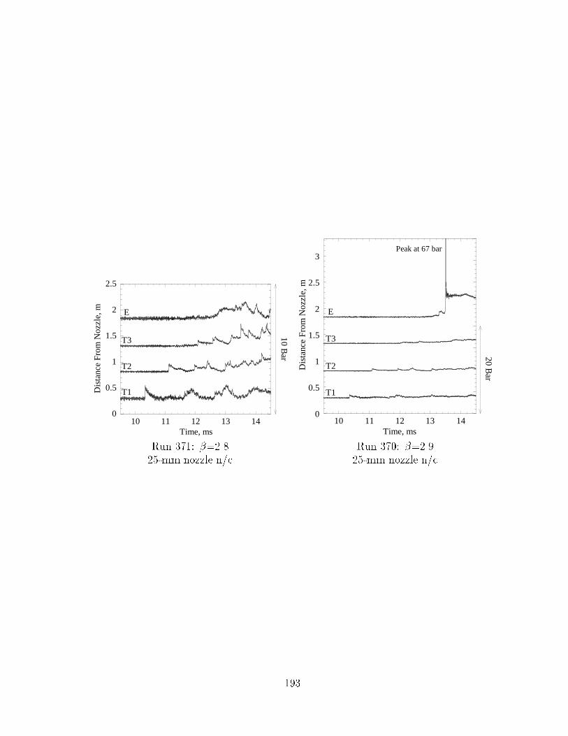
Run ���� ���� Run ���� ������� mm nozzle n�c �� mm nozzle n�c
���
0
0.5
1
1.5
2
2.5
10 11 12 13 14
Dis
tanc
e Fr
om N
ozzl
e, m
Time, ms
10 Bar
E
T3
T2
T1
0
0.5
1
1.5
2
2.5
3
10 11 12 13 14
Dis
tanc
e Fr
om N
ozzl
e, m
Time, ms
Peak at 67 bar
20 Bar
E
T3
T2
T1
Run ���� ����� Run ���� ������� mm nozzle n�c �� mm nozzle n�c
���
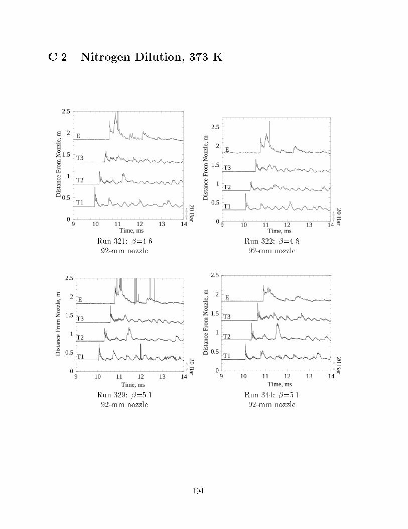
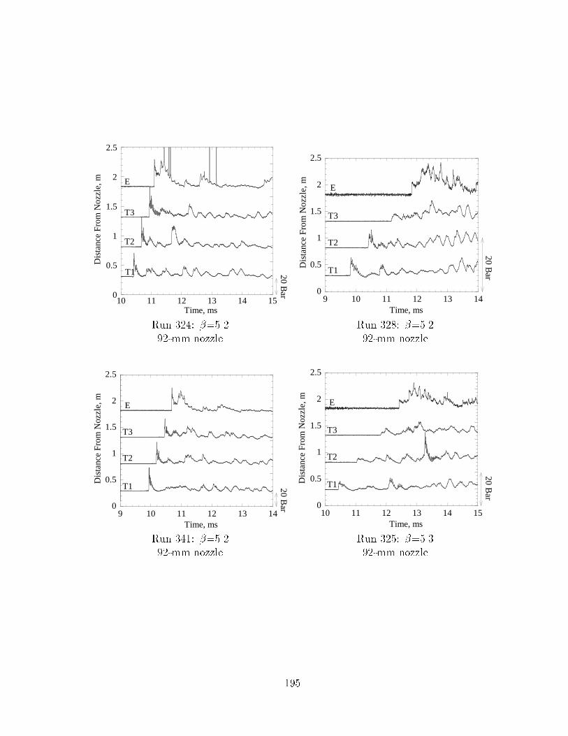
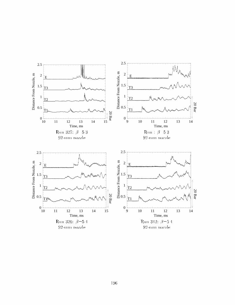
C�� Nitrogen Dilution� ��� K
0
0.5
1
1.5
2
2.5
9 10 11 12 13 14
Dis
tanc
e Fr
om N
ozzl
e, m
Time, ms
E
T3
T2
T1 20 Bar 0
0.5
1
1.5
2
2.5
9 10 11 12 13 14
Dis
tanc
e Fr
om N
ozzl
e, m
Time, ms
20 Bar
E
T3
T2
T1
Run ���� ��� Run ���� ������ mm nozzle �� mm nozzle
0
0.5
1
1.5
2
2.5
9 10 11 12 13 14
Dis
tanc
e Fr
om N
ozzl
e, m
Time, ms
20 Bar
E
T3
T2
T1
0
0.5
1
1.5
2
2.5
9 10 11 12 13 14
Dis
tanc
e Fr
om N
ozzl
e, m
Time, ms
20 Bar
E
T3
T2
T1
Run ���� ����� Run �� ������� mm nozzle �� mm nozzle
��
0
0.5
1
1.5
2
2.5
10 11 12 13 14 15
Dis
tanc
e Fr
om N
ozzl
e, m
Time, ms
20 Bar
E
T3
T2
T1
0
0.5
1
1.5
2
2.5
9 10 11 12 13 14D
ista
nce
Fro
m N
ozzl
e, m
Time, ms
20 Bar
E
T3
T2
T1
Run ��� ����� Run ���� ������� mm nozzle �� mm nozzle
0
0.5
1
1.5
2
2.5
9 10 11 12 13 14
Dis
tanc
e Fr
om N
ozzl
e, m
Time, ms
20 Bar
E
T3
T2
T1
0
0.5
1
1.5
2
2.5
10 11 12 13 14 15
Dis
tanc
e Fr
om N
ozzl
e, m
Time, ms
20 Bar
E
T3
T2
T1
Run ��� ����� Run ���� ������� mm nozzle �� mm nozzle
���
0
0.5
1
1.5
2
2.5
10 11 12 13 14 15
Dis
tanc
e Fr
om N
ozzl
e, m
Time, ms20 B
ar
E
T3
T2
T1
0
0.5
1
1.5
2
2.5
9 10 11 12 13 14D
ista
nce
From
Noz
zle,
m
Time, ms
20 Bar
E
T3
T2
T1
Run ���� ����� Run � ������� mm nozzle �� mm nozzle
0
0.5
1
1.5
2
2.5
10 11 12 13 14 15
Dis
tanc
e Fr
om N
ozzl
e, m
Time, ms
20 Bar
E
T3
T2
T1
0
0.5
1
1.5
2
2.5
9 10 11 12 13 14
Dis
tanc
e F
rom
Noz
zle,
m
Time, ms
20 Bar
E
T3
T2
T1
Run ��� ���� Run ��� ������ mm nozzle �� mm nozzle
��
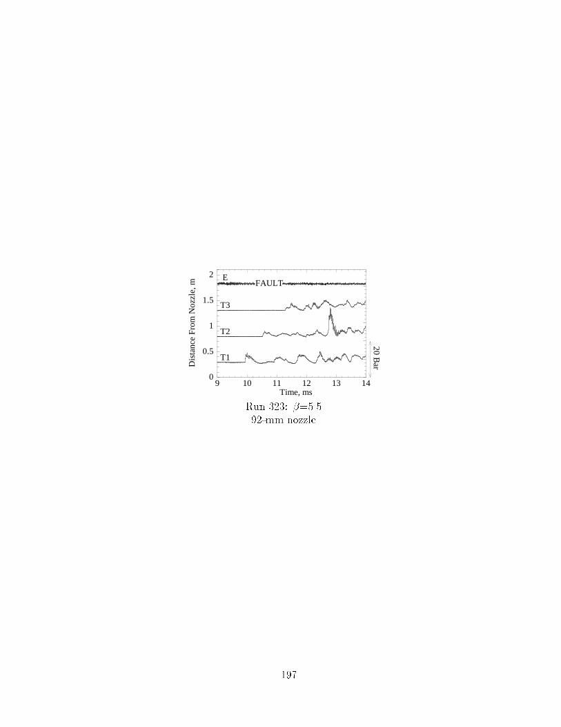
0
0.5
1
1.5
2
9 10 11 12 13 14
Dis
tanc
e Fr
om N
ozzl
e, m
Time, ms
20 Bar
E
T3
T2
T1
FAULT
Run ���� ������� mm nozzle
���
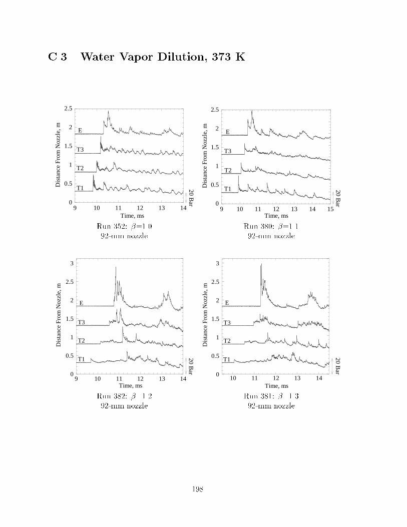
C�� Water Vapor Dilution� ��� K
0
0.5
1
1.5
2
2.5
9 10 11 12 13 14
Dis
tanc
e Fr
om N
ozzl
e, m
Time, ms20 B
ar
E
T3
T2
T1
0
0.5
1
1.5
2
2.5
9 10 11 12 13 14 15D
ista
nce
From
Noz
zle,
m
Time, ms
20 Bar
E
T3
T2
T1
Run ���� ����� Run ���� ������� mm nozzle �� mm nozzle
0
0.5
1
1.5
2
2.5
3
9 10 11 12 13 14
Dis
tanc
e Fr
om N
ozzl
e, m
Time, ms
20 Bar
E
T3
T2
T1
0
0.5
1
1.5
2
2.5
3
10 11 12 13 14
Dis
tanc
e Fr
om N
ozzl
e, m
Time, ms
20 Bar
E
T3
T2
T1
Run ���� ����� Run ���� ������� mm nozzle �� mm nozzle
���

0
0.5
1
1.5
2
2.5
3
9 10 11 12 13 14
Dis
tanc
e Fr
om N
ozzl
e, m
Time, ms
20 Bar
E
T3
T2
T1
0
0.5
1
1.5
2
2.5
10 11 12 13 14 15D
ista
nce
From
Noz
zle,
m
Time, ms
20 bar
E
T3
T2
T1
Run ���� ���� Run ���� ������ mm nozzle �� mm nozzle
0
0.5
1
1.5
2
2.5
9 10 11 12 13 14
Dis
tanc
e F
rom
Noz
zle,
m
Time, ms
20 Bar
E
T3
T2
T1
0
0.5
1
1.5
2
2.5
10 11 12 13 14 15
Dis
tanc
e Fr
om N
ozzl
e, m
Time, ms
20 Bar
E
T3
T2
T1
Run ��� ����� Run ��� ������� mm nozzle �� mm nozzle
���

0
0.5
1
1.5
2
2.5
9 10 11 12 13 14
Dis
tanc
e F
rom
Noz
zle,
m
Time, ms20 B
ar
E
T3
T2
T1
0
0.5
1
1.5
2
2.5
10 11 12 13 14 15D
ista
nce
From
Noz
zle,
m
Time, ms
20 Bar
E
T3
T2
T1
Noise reaches xducermax of 135
Run ��� ���� Run ���� ������� mm nozzle �� mm nozzle
0
0.5
1
1.5
2
2.5
10 11 12 13 14 15
Dis
tanc
e Fr
om N
ozzl
e, m
Time, ms
20 Bar
E
T3
T2
T1
0
0.5
1
1.5
2
2.5
10 11 12 13 14 15
Dis
tanc
e Fr
om N
ozzl
e, m
Time, ms
20 Bar
E
T3
T2
T1
Run �� ����� Run ��� ������� mm nozzle �� mm nozzle
���
0
0.5
1
1.5
2
2.5
9 10 11 12 13 14
Dis
tanc
e Fr
om N
ozzl
e, m
Time, ms
20 Bar
E
T3
T2
T1
0
0.5
1
1.5
2
2.5
10 11 12 13 14 15D
ista
nce
From
Noz
zle,
mTime, ms
20 Bar
E
T3
T2
T1
Run ���� ����� Run ���� ������mm nozzle ��mm nozzle
0
0.5
1
1.5
2
2.5
9 10 11 12 13 14
Dis
tanc
e Fr
om N
ozzl
e, m
Time, ms
20 Bar
E
T3
T2
T1
0
0.5
1
1.5
2
2.5
9 10 11 12 13 14
Dis
tanc
e Fr
om N
ozzl
e, m
Time, ms
20 Bar
E
T3
T2
T1
Run � � ���� Run � � ����� �mm nozzle � �mm nozzle
���
0
0.5
1
1.5
2
2.5
10 11 12 13 14
Dis
tanc
e Fr
om N
ozzl
e, m
Time, ms20 B
ar
E
T3
T2
T1
0
0.5
1
1.5
2
2.5
10 11 12 13 14D
ista
nce
From
Noz
zle,
m
Time, ms
20 Bar
E
T3
T2
T1
Run ��� ����� Run � �� ������� �mm nozzle � �mm nozzle
0
0.5
1
1.5
2
2.5
10 11 12 13 14
Dis
tanc
e Fr
om N
ozzl
e, m
Time, ms
E
T3
T2
T1 20 Bar 0
0.5
1
1.5
2
2.5
10 11 12 13 14
Dis
tanc
e Fr
om N
ozzl
e, m
Time, ms
E
T3
T2
T1
20 Bar
Run � � ����� Run ��� ���� � �mm nozzle � �mm nozzle
���
0
0.5
1
1.5
2
2.5
10 11 12 13 14
Dis
tanc
e Fr
om N
ozzl
e, m
Time, ms
20 Bar
E
T3
T2
T1
Run � �� ���� �� �mm nozzle
���
C�� Nitrogen Dilution� ��� K� No Diaphragm
0
0.5
1
1.5
2
2.5
11 12 13 14 15
Dis
tanc
e Fr
om N
ozzl
e, m
Time, ms
E
T3
T2
T1 20 Bar 0
0.5
1
1.5
2
2.5
12 13 14 15 16 17
Dis
tanc
e Fr
om N
ozzl
e, m
Time, ms
E
T3
T2
T1 20 Bar
Run ��� ����� Run ��� �������mm nozzle ��mm nozzle
0
0.5
1
1.5
2
2.5
14 15 16 17 18 19
Dis
tanc
e Fr
om N
ozzl
e, m
Time, ms
20 Bar
E
T3
T2
T1
0
0.5
1
1.5
2
2.5
15 16 17 18 19 20
Dis
tanc
e Fr
om N
ozzl
e, m
Time, ms
E
T3
T2
T1
20 Bar
Run ��� ������ Run ��� ��������mm nozzle ��mm nozzle
���
0
0.5
1
1.5
2
2.5
16 17 18 19 20 21
Dis
tanc
e Fr
om N
ozzl
e, m
Time, ms
20 Bar
E
T3
T2
T1
0
0.5
1
1.5
2
2.5
5 6 7 8 9 10D
ista
nce
Fro
m N
ozzl
e, m
Time, ms
20 Bar
E
T3
T2
T1
Run �� ����� Run ���� ������mm nozzle ��mm nozzle w�c
0
0.5
1
1.5
2
2.5
7 8 9 10 11
Dis
tanc
e Fr
om N
ozzl
e, m
Time, ms
20 Bar
E
T3
T2
T1
0
0.5
1
1.5
2
2.5
5 6 7 8 9 10
Dis
tanc
e Fr
om N
ozzl
e, m
Time, ms
20 Bar
E
T3
T2
T1
Run ���� ���� Run ���� �������mm nozzle w�c ��mm nozzle w�c
��

0
0.5
1
1.5
2
2.5
13 14 15 16 17 18
Dis
tanc
e Fr
om N
ozzl
e, m
Time, ms20 B
ar
E
T3
T2
T1
0
0.5
1
1.5
2
2.5
11 12 13 14 15 16D
ista
nce
From
Noz
zle,
m
Time, ms
20 Bar
E
T3
T2
T1
Run ���� ����� Run ��� ���� ��mm nozzle w�c ��mm nozzle w�c
0
0.5
1
1.5
2
2.5
10 11 12 13 14 15
Dis
tanc
e Fr
om N
ozzl
e, m
Time, ms
20 Bar
E
T3
T2
T1
0
0.5
1
1.5
2
2.5
5 6 7 8 9 10
Dis
tanc
e Fr
om N
ozzl
e, m
Time, ms
20 Bar
E
T3
T2
T1
Run ���� ���� Run ���� ���� ��mm nozzle w�c ��mm nozzle w�c
���

0
0.5
1
1.5
2
2.5
7 8 9 10 11
Dis
tanc
e Fr
om N
ozzl
e, m
Time, ms
E
T3
T2
T1
10 Bar
0
0.5
1
1.5
2
2.5
8 9 10 11 12 13D
ista
nce
From
Noz
zle,
mTime, ms
E
T3
T2
T1
10 Bar
Run ���� ����� Run �� �������mm nozzle w�c ��mm nozzle w�c
0
0.5
1
1.5
2
2.5
9 10 11 12 13
Dis
tanc
e Fr
om N
ozzl
e, m
Time, ms
10 Bar
E
T3
T2
T1
Run � � �������mm nozzle w�c
���

��
AppendixD
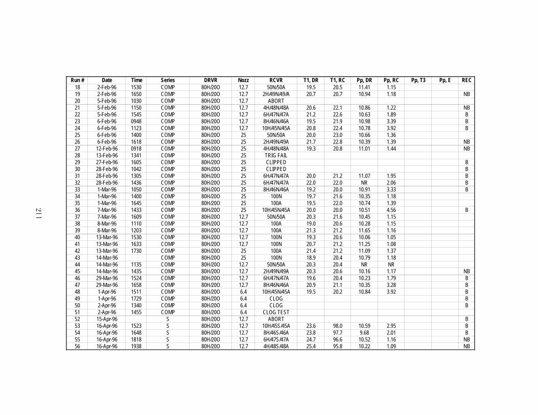
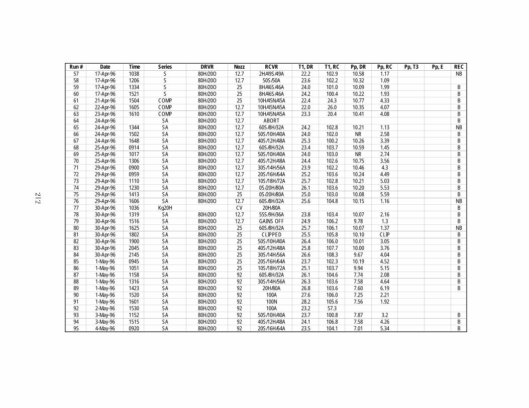
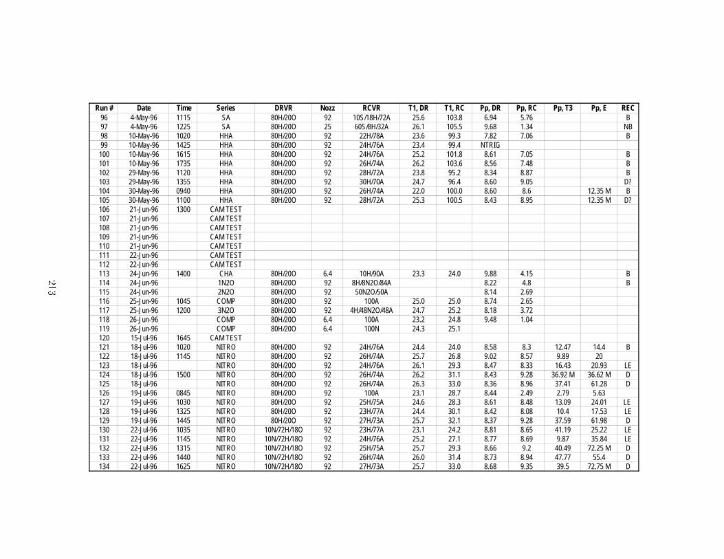
RunSummary
Thisappendix
contain
satab
lesummarizin
gall
oftherunsperform
edin
thisresearch
�Thecolu
mnhead
ings
areas
follows�
��RunNumber�
Sequential
numbers
used
toidentify
eachrun�as
aserial
number�
��Date
��Tim
e
��Serie
s�Indicates
theseries
that
eachrunwas
part
of�as
describ
edin
thetex
t�TheCHA
andHHA
series�not
describ
edin
thetex
t�are
generic
termsfor
Cold
Hydrogen
Air
���K andHot
Hydrogen
Air
���K �
respectively�
These
were
used
astest
runs�
Other
testrunsare
listedhere
aswell�
��DRVR�Gas
mixture
indriv
er�as
percen
tages�A�air�
H�hydrogen
�N�nitrogen
�O�oxygen
�S�steam
gaseousH
� O �
��Nozz�
Nozzle
diam
eter�in
mm�
Addition
alcod
esare�
NC�nocutter
nozzle
diam
eters��
mm
andsm
alleruse
adiap
hragm
cutter
bydefau
lt �CV�con
stant
volumetest
nozzle
plugged
�ND�nodiap
hragm
�
��RCVR�Gas
mixture
inreceiv
er�form
atsam
eas
DRVR�
��T��DR�Initial
temperatu
rein
driv
er�in
�C�
��T��RC�Initial
temperatu
rein
receiver�
in�C
�
���P
p �DR�Peak
pressu
remeasu
redbydriver
Kulite�
bars�
���P
p �RC�Peak
pressu
remeasu
redbyreceiv
erKulite�
bars�
���P
p �T��Peak
pressu
remeasu
redbyPCBin
T�position
�bars�
���P
p �E�Peak
pressu
remeasu
redbyPCBin
Eposition
�bars�
���

���REC�Receiver
Even
tCode�
Describ
esresu
ltingeventin
receiver
vessel�
B�
burn
de�agration
�D�deton
ationprom
ptinitiation
�T�tran
sitionto
deton
ation
DDT �LE�late
orsecon
dary
explosion
�Ifblan
k�receiv
erwas
inert�
afau
ltoccu
rred�or
runwas
asystem
stest����
Run # Date Time Series DRVR Nozz RCVR T1, DR T1, RC Pp, DR Pp, RC Pp, T3 Pp, E REC18 2-Feb-96 1530 COMP 80H/20O 12.7 50N/50A 19.5 20.5 11.41 1.1519 2-Feb-96 1650 COMP 80H/20O 12.7 2H/49N/49/A 20.7 20.7 10.94 1.18 NB20 5-Feb-96 1030 COMP 80H/20O 12.7 ABORT21 5-Feb-96 1150 COMP 80H/20O 12.7 4H/48N/48A 20.6 22.1 10.86 1.22 NB22 5-Feb-96 1545 COMP 80H/20O 12.7 6H/47N/47A 21.2 22.6 10.63 1.89 B23 6-Feb-96 0948 COMP 80H/20O 12.7 8H/46N/46A 19.5 21.9 10.98 3.39 B24 6-Feb-96 1123 COMP 80H/20O 12.7 10H/45N/45A 20.8 22.4 10.78 3.92 B25 6-Feb-96 1400 COMP 80H/20O 25 50N/50A 20.0 23.0 10.66 1.3626 6-Feb-96 1618 COMP 80H/20O 25 2H/49N/49A 21.7 22.8 10.39 1.39 NB27 12-Feb-96 0918 COMP 80H/20O 25 4H/48N/48A 19.3 20.8 11.01 1.44 NB28 13-Feb-96 1341 COMP 80H/20O 25 TRIG FAIL29 27-Feb-96 1605 COMP 80H/20O 25 CLIPPED B30 28-Feb-96 1042 COMP 80H/20O 25 CLIPPED B31 28-Feb-96 1305 COMP 80H/20O 25 6H/47N/47A 20.0 21.2 11.07 1.95 B32 28-Feb-96 1436 COMP 80H/20O 25 6H/47N/47A 22.0 22.0 NR 2.06 B33 1-Mar-96 1050 COMP 80H/20O 25 8H/46N/46A 19.2 20.0 10.91 3.33 B34 1-Mar-96 1400 COMP 80H/20O 25 100N 19.7 21.6 10.35 1.1835 1-Mar-96 1645 COMP 80H/20O 25 100A 19.5 22.0 10.74 1.3936 7-Mar-96 1433 COMP 80H/20O 25 10H/45N/45A 20.0 20.0 10.51 4.56 B37 7-Mar-96 1609 COMP 80H/20O 12.7 50N/50A 20.3 21.6 10.45 1.1538 8-Mar-96 1110 COMP 80H/20O 12.7 100A 19.0 20.6 10.28 1.1539 8-Mar-96 1203 COMP 80H/20O 12.7 100A 21.3 21.2 11.65 1.1640 13-Mar-96 1530 COMP 80H/20O 12.7 100N 19.3 20.6 10.06 1.0541 13-Mar-96 1633 COMP 80H/20O 12.7 100N 20.7 21.2 11.25 1.0842 13-Mar-96 1730 COMP 80H/20O 25 100A 21.4 21.2 11.09 1.3743 14-Mar-96 COMP 80H/20O 25 100N 18.9 20.4 10.79 1.1844 14-Mar-96 1135 COMP 80H/20O 12.7 50N/50A 20.3 20.4 NR NR45 14-Mar-96 1435 COMP 80H/20O 12.7 2H/49N/49A 20.3 20.6 10.16 1.17 NB46 29-Mar-96 1524 COMP 80H/20O 12.7 6H/47N/47A 19.6 20.4 10.23 1.79 B47 29-Mar-96 1658 COMP 80H/20O 12.7 8H/46N/46A 20.9 21.1 10.35 3.28 B48 1-Apr-96 1511 COMP 80H/20O 6.4 10H/45N/45A 19.5 20.2 10.84 3.92 B49 1-Apr-96 1729 COMP 80H/20O 6.4 CLOG B50 2-Apr-96 1340 COMP 80H/20O 6.4 CLOG B51 2-Apr-96 1455 COMP 80H/20O 6.4 CLOG TEST52 15-Apr-96 S 80H/20O 12.7 ABORT B53 16-Apr-96 1523 S 80H/20O 12.7 10H/45S/45A 23.6 98.0 10.59 2.95 B54 16-Apr-96 1648 S 80H/20O 12.7 8H/46S/46A 23.8 97.7 9.68 2.01 B55 16-Apr-96 1818 S 80H/20O 12.7 6H/47S/47A 24.7 96.6 10.52 1.16 NB56 16-Apr-96 1938 S 80H/20O 12.7 4H/48S/48A 25.4 95.8 10.22 1.09 NB
���
Run # Date Time Series DRVR Nozz RCVR T1, DR T1, RC Pp, DR Pp, RC Pp, T3 Pp, E REC57 17-Apr-96 1038 S 80H/20O 12.7 2H/49S/49A 22.2 102.9 10.58 1.17 NB58 17-Apr-96 1206 S 80H/20O 12.7 50S/50A 23.6 102.2 10.32 1.0959 17-Apr-96 1334 S 80H/20O 25 8H/46S/46A 24.0 101.0 10.09 1.99 B60 17-Apr-96 1521 S 80H/20O 25 8H/46S/46A 24.2 100.4 10.22 1.93 B61 21-Apr-96 1504 COMP 80H/20O 25 10H/45N/45A 22.4 24.3 10.77 4.33 B62 22-Apr-96 1605 COMP 80H/20O 12.7 10H/45N/45A 22.0 26.0 10.35 4.07 B63 23-Apr-96 1610 COMP 80H/20O 12.7 10H/45N/45A 23.3 20.4 10.41 4.08 B64 24-Apr-96 SA 80H/20O 12.7 ABORT B65 24-Apr-96 1344 SA 80H/20O 12.7 60S/8H/32A 24.2 102.8 10.21 1.13 NB66 24-Apr-96 1502 SA 80H/20O 12.7 50S/10H/40A 24.0 102.0 NR 2.58 B67 24-Apr-96 1648 SA 80H/20O 12.7 40S/12H/48A 25.3 100.2 10.26 3.39 B68 25-Apr-96 0914 SA 80H/20O 12.7 60S/8H/32A 23.4 103.7 10.59 1.45 B69 25-Apr-96 1017 SA 80H/20O 12.7 50S/10H/40A 24.0 103.0 NR 2.74 B70 25-Apr-96 1306 SA 80H/20O 12.7 40S/12H/48A 24.4 102.6 10.75 3.56 B71 29-Apr-96 0900 SA 80H/20O 12.7 30S/14H/56A 23.9 102.2 10.46 4.3 B72 29-Apr-96 0959 SA 80H/20O 12.7 20S/16H/64A 25.2 103.6 10.24 4.49 B73 29-Apr-96 1110 SA 80H/20O 12.7 10S/18H/72A 25.7 102.8 10.21 5.03 B74 29-Apr-96 1230 SA 80H/20O 12.7 0S/20H/80A 26.1 103.6 10.20 5.53 B75 29-Apr-96 1413 SA 80H/20O 25 0S/20H/80A 25.0 103.0 10.08 5.59 B76 29-Apr-96 1606 SA 80H/20O 12.7 60S/8H/32A 25.6 104.8 10.15 1.16 NB77 30-Apr-96 1036 Kg20H CV 20H/80A B78 30-Apr-96 1319 SA 80H/20O 12.7 55S/9H/36A 23.8 103.4 10.07 2.16 B79 30-Apr-96 1516 SA 80H/20O 12.7 GAINS OFF 24.9 106.2 9.78 1.3 B80 30-Apr-96 1625 SA 80H/20O 25 60S/8H/32A 25.7 106.1 10.07 1.37 NB81 30-Apr-96 1802 SA 80H/20O 25 CLIPPED 25.5 105.8 10.10 CLIP B82 30-Apr-96 1900 SA 80H/20O 25 50S/10H/40A 26.4 106.0 10.01 3.05 B83 30-Apr-96 2045 SA 80H/20O 25 40S/12H/48A 25.8 107.7 10.00 3.76 B84 30-Apr-96 2145 SA 80H/20O 25 30S/14H/56A 26.6 108.3 9.67 4.04 B85 1-May-96 0945 SA 80H/20O 25 20S/16H/64A 23.7 102.3 10.19 4.52 B86 1-May-96 1051 SA 80H/20O 25 10S/18H/72A 25.1 103.7 9.94 5.15 B87 1-May-96 1158 SA 80H/20O 92 60S/8H/32A 26.1 104.6 7.74 2.08 B88 1-May-96 1316 SA 80H/20O 92 30S/14H/56A 26.3 103.6 7.58 4.64 B89 1-May-96 1423 SA 80H/20O 92 20H/80A 26.8 103.6 7.60 6.19 B90 1-May-96 1520 SA 80H/20O 92 100A 27.6 106.0 7.25 2.2191 1-May-96 1601 SA 80H/20O 92 100N 28.2 105.6 7.56 1.9292 2-May-96 1530 SA 80H/20O 92 100A 23.2 57.393 3-May-96 1152 SA 80H/20O 92 50S/10H/40A 23.7 100.8 7.87 3.2 B94 3-May-96 1515 SA 80H/20O 92 40S/12H/48A 24.1 106.8 7.58 4.26 B95 4-May-96 0920 SA 80H/20O 92 20S/16H/64A 23.5 104.1 7.01 5.34 B
���
Run # Date Time Series DRVR Nozz RCVR T1, DR T1, RC Pp, DR Pp, RC Pp, T3 Pp, E REC96 4-May-96 1115 SA 80H/20O 92 10S/18H/72A 25.6 103.8 6.94 5.76 B97 4-May-96 1225 SA 80H/20O 25 60S/8H/32A 26.1 105.5 9.68 1.34 NB98 10-May-96 1020 HHA 80H/20O 92 22H/78A 23.6 99.3 7.82 7.06 B99 10-May-96 1425 HHA 80H/20O 92 24H/76A 23.4 99.4 NTRIG100 10-May-96 1615 HHA 80H/20O 92 24H/76A 25.2 101.8 8.61 7.05 B101 10-May-96 1735 HHA 80H/20O 92 26H/74A 26.2 103.6 8.56 7.48 B102 29-May-96 1120 HHA 80H/20O 92 28H/72A 23.8 95.2 8.34 8.87 B103 29-May-96 1355 HHA 80H/20O 92 30H/70A 24.7 96.4 8.60 9.05 D?104 30-May-96 0940 HHA 80H/20O 92 26H/74A 22.0 100.0 8.60 8.6 12.35 M B105 30-May-96 1100 HHA 80H/20O 92 28H/72A 25.3 100.5 8.43 8.95 12.35 M D?106 21-Jun-96 1300 CAM TEST107 21-Jun-96 CAM TEST108 21-Jun-96 CAM TEST109 21-Jun-96 CAM TEST110 21-Jun-96 CAM TEST111 22-Jun-96 CAM TEST112 22-Jun-96 CAM TEST113 24-Jun-96 1400 CHA 80H/20O 6.4 10H/90A 23.3 24.0 9.88 4.15 B114 24-Jun-96 1N2O 80H/20O 92 8H/8N2O/84A 8.22 4.8 B115 24-Jun-96 2N2O 80H/20O 92 50N2O/50A 8.14 2.69116 25-Jun-96 1045 COMP 80H/20O 92 100A 25.0 25.0 8.74 2.65117 25-Jun-96 1200 3N2O 80H/20O 92 4H/48N2O/48A 24.7 25.2 8.18 3.72118 26-Jun-96 COMP 80H/20O 6.4 100A 23.2 24.8 9.48 1.04119 26-Jun-96 COMP 80H/20O 6.4 100N 24.3 25.1120 15-Jul-96 1645 CAM TEST121 18-Jul-96 1020 NITRO 80H/20O 92 24H/76A 24.4 24.0 8.58 8.3 12.47 14.4 B122 18-Jul-96 1145 NITRO 80H/20O 92 26H/74A 25.7 26.8 9.02 8.57 9.89 20123 18-Jul-96 NITRO 80H/20O 92 24H/76A 26.1 29.3 8.47 8.33 16.43 20.93 LE124 18-Jul-96 1500 NITRO 80H/20O 92 26H/74A 26.2 31.1 8.43 9.28 36.92 M 36.62 M D125 18-Jul-96 NITRO 80H/20O 92 26H/74A 26.3 33.0 8.36 8.96 37.41 61.28 D126 19-Jul-96 0845 NITRO 80H/20O 92 100A 23.1 28.7 8.44 2.49 2.79 5.63127 19-Jul-96 1030 NITRO 80H/20O 92 25H/75A 24.6 28.3 8.61 8.48 13.09 24.01 LE 128 19-Jul-96 1325 NITRO 80H/20O 92 23H/77A 24.4 30.1 8.42 8.08 10.4 17.53 LE129 19-Jul-96 1445 NITRO 80H/20O 92 27H/73A 25.7 32.1 8.37 9.28 37.59 61.98 D130 22-Jul-96 1035 NITRO 10N/72H/18O 92 23H/77A 23.1 24.2 8.81 8.65 41.19 25.22 LE131 22-Jul-96 1145 NITRO 10N/72H/18O 92 24H/76A 25.2 27.1 8.77 8.69 9.87 35.84 LE132 22-Jul-96 1315 NITRO 10N/72H/18O 92 25H/75A 25.7 29.3 8.66 9.2 40.49 72.25 M D133 22-Jul-96 1440 NITRO 10N/72H/18O 92 26H/74A 26.0 31.4 8.73 8.94 47.77 55.4 D134 22-Jul-96 1625 NITRO 10N/72H/18O 92 27H/73A 25.7 33.0 8.68 9.35 39.5 72.75 M D
���

Run # Date Time Series DRVR Nozz RCVR T1, DR T1, RC Pp, DR Pp, RC Pp, T3 Pp, E REC135 22-Jul-96 1805 NITRO 20N/64H/16O 92 24H/76A 25.7 34.6 10.19 8.34 8.92 26.23 LE136 23-Jul-96 1010 NITRO 20N/64H/16O 92 25H/75A 23.4 28.9 10.04 8.4 19.59 22.16 LE137 23-Jul-96 1225 NITRO 20N/64H/16O 92 26H/74A 24.4 30.9 10.11 9.42 47.75 72.75 M D138 23-Jul-96 1445 NITRO 50N/40H/10O 92 25H/75A 25.2 32.5 BURN TOO SLOW B139 23-Jul-96 1600 NITRO 50N/40H/10O 92 25H/75A 25.9 34.6 8.63 8.04 7.5 17.11 LE140 24-Jul-96 0940 NITRO 30N/56H/14O 92 CONTAMINATED D141 24-Jul-96 1100 NITRO 30N/56H/14O 92 25H/75A 25.3 31.4 8.70 8.45 12.81 21.01 LE142 24-Jul-96 1520 NITRO 30N/56H/14O 92 24H/76A 25.2 31.8 8.48 8.11 11.36 20.49 LE143 24-Jul-96 1650 NITRO 30N/56H/14O 92 26H/74A 25.7 33.8 8.94 8.33 14.54 12.31 B144 25-Jul-96 1035 NITRO 30N/56H/14O 92 27H/73A 23.9 28.4 9.13 8.4 8.88 10.31 B145 25-Jul-96 1215 NITRO 30N/56H/14O 92 28H/72A 24.8 31.2 9.03 8.76 30.73 13.36 LE146 25-Jul-96 1355 NITRO 30N/56H/14O 92 30H/70A 25.4 33.3 LE147 25-Jul-96 1555 NITRO 25N/60H/15O 92 30H/70A 25.2 34.9 10.30 9.41 42.18 85.66 D148 25-Jul-96 1655 NITRO 25N/60H/15O 92 28H/72A 26.3 37.4 10.35 9.27 38.33 83.23 D149 26-Jul-96 0940 NITRO 25N/60H/15O 92 26H/74A 23.5 29.8 10.86 9.4 42.29 80.62 D150 26-Jul-96 1105 NITRO 25N/60H/15O 92 24H/76A 25.0 32.4 10.37 8.88 32.39 64.26 D151 26-Jul-96 1310 NITRO 25N/60H/15O 92 22H/78A 25.1 33.7 10.56 9.02 34.41 101.67 LE152 26-Jul-96 1425 NITRO 25N/60H/15O 92 23H/77A 25.8 35.3 10.26 11.05 25.25 100.98 LE153 26-Jul-96 1605 NITRO 25N/60H/15O 92 100A 27.1 37.2 10.31 1.9 3.19 6.66154 29-Jul-96 1335 NITRO 25N/60H/15O 92 23H/77A 23.3 24.4 10.13 8.79 9.8 48.86 LE155 29-Jul-96 1450 NITRO 80H/20O 92 23H/77A 24.9 27.2 8.35 8.12 14.82 25.62 LE156 30-Jul-96 1000 NITRO 80H/20O CV N/A 23.3 10.03157 30-Jul-96 1305 NITRO 5N/76H/19O CV N/A 24.2 10.45158 30-Jul-96 1335 NITRO 10N/72H/18O CV N/A 26.5 10.93159 30-Jul-96 1435 NITRO 15N/68H/17O CV N/A 30.0 11.10160 30-Jul-96 1542 NITRO 20N/64H/16O CV N/A 29.1 12.66161 30-Jul-96 1633 NITRO 25N/60H/15O CV N/A 29.1 12.96162 31-Jul-96 1037 NITRO 30N/56H/14O CV N/A 23.9 12.80163 31-Jul-96 1115 NITRO 35N/52H/13O CV N/A 26.2 12.85164 31-Jul-96 1235 NITRO 40N/48H/12O CV N/A 28.7 11.93165 31-Jul-96 1315 NITRO 45N/44H/11O CV N/A 29.1 8.36166 31-Jul-96 1503 NITRO 50N/40H/10O CV N/A 27.1 8.20167 31-Jul-96 1540 NITRO 55N/36H/9O CV N/A 28.3 7.19168 5-Aug-96 1610 NITRO 20N/64H/16O 92 27H/73A 23.5 23.7 9.47 9.65 50.39 97.32 D169 6-Aug-96 1033 NITRO 20N/64H/16O 92 25H/75A 23.2 24.7 9.86 9.23 23.94 72.96 LE170 6-Aug-96 1145 NITRO 25N/60H/15O 92 25H/75A 25.3 27.8 10.51 8.87 45.67 51.99 D171 6-Aug-96 1440 NITRO 67H/33O 92 100A 24.6 29.7 3.20 2.4 2.77 9.46172 7-Aug-96 1015 NITRO 25N/60H/15O 92 21H/79A 23.4 25.7 10.53 7.98 11.25 51.03 LE173 7-Aug-96 1145 NITRO 25N/60H/15O 92 20H/80A 25.1 28.2 10.18 7.87 12.21 20.93 LE
���
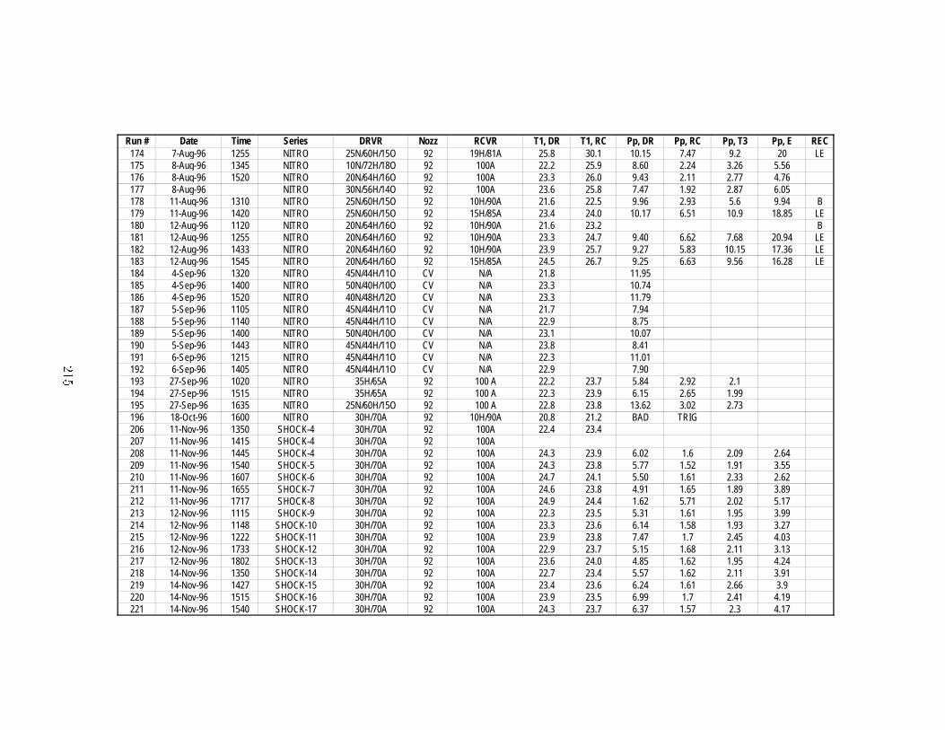
Run # Date Time Series DRVR Nozz RCVR T1, DR T1, RC Pp, DR Pp, RC Pp, T3 Pp, E REC174 7-Aug-96 1255 NITRO 25N/60H/15O 92 19H/81A 25.8 30.1 10.15 7.47 9.2 20 LE175 8-Aug-96 1345 NITRO 10N/72H/18O 92 100A 22.2 25.9 8.60 2.24 3.26 5.56176 8-Aug-96 1520 NITRO 20N/64H/16O 92 100A 23.3 26.0 9.43 2.11 2.77 4.76177 8-Aug-96 NITRO 30N/56H/14O 92 100A 23.6 25.8 7.47 1.92 2.87 6.05178 11-Aug-96 1310 NITRO 25N/60H/15O 92 10H/90A 21.6 22.5 9.96 2.93 5.6 9.94 B179 11-Aug-96 1420 NITRO 25N/60H/15O 92 15H/85A 23.4 24.0 10.17 6.51 10.9 18.85 LE180 12-Aug-96 1120 NITRO 20N/64H/16O 92 10H/90A 21.6 23.2 B181 12-Aug-96 1255 NITRO 20N/64H/16O 92 10H/90A 23.3 24.7 9.40 6.62 7.68 20.94 LE182 12-Aug-96 1433 NITRO 20N/64H/16O 92 10H/90A 23.9 25.7 9.27 5.83 10.15 17.36 LE183 12-Aug-96 1545 NITRO 20N/64H/16O 92 15H/85A 24.5 26.7 9.25 6.63 9.56 16.28 LE184 4-Sep-96 1320 NITRO 45N/44H/11O CV N/A 21.8 11.95185 4-Sep-96 1400 NITRO 50N/40H/10O CV N/A 23.3 10.74186 4-Sep-96 1520 NITRO 40N/48H/12O CV N/A 23.3 11.79187 5-Sep-96 1105 NITRO 45N/44H/11O CV N/A 21.7 7.94188 5-Sep-96 1140 NITRO 45N/44H/11O CV N/A 22.9 8.75189 5-Sep-96 1400 NITRO 50N/40H/10O CV N/A 23.1 10.07190 5-Sep-96 1443 NITRO 45N/44H/11O CV N/A 23.8 8.41191 6-Sep-96 1215 NITRO 45N/44H/11O CV N/A 22.3 11.01192 6-Sep-96 1405 NITRO 45N/44H/11O CV N/A 22.9 7.90193 27-Sep-96 1020 NITRO 35H/65A 92 100 A 22.2 23.7 5.84 2.92 2.1194 27-Sep-96 1515 NITRO 35H/65A 92 100 A 22.3 23.9 6.15 2.65 1.99195 27-Sep-96 1635 NITRO 25N/60H/15O 92 100 A 22.8 23.8 13.62 3.02 2.73196 18-Oct-96 1600 NITRO 30H/70A 92 10H/90A 20.8 21.2 BAD TRIG206 11-Nov-96 1350 SHOCK-4 30H/70A 92 100A 22.4 23.4207 11-Nov-96 1415 SHOCK-4 30H/70A 92 100A208 11-Nov-96 1445 SHOCK-4 30H/70A 92 100A 24.3 23.9 6.02 1.6 2.09 2.64209 11-Nov-96 1540 SHOCK-5 30H/70A 92 100A 24.3 23.8 5.77 1.52 1.91 3.55210 11-Nov-96 1607 SHOCK-6 30H/70A 92 100A 24.7 24.1 5.50 1.61 2.33 2.62211 11-Nov-96 1655 SHOCK-7 30H/70A 92 100A 24.6 23.8 4.91 1.65 1.89 3.89212 11-Nov-96 1717 SHOCK-8 30H/70A 92 100A 24.9 24.4 1.62 5.71 2.02 5.17213 12-Nov-96 1115 SHOCK-9 30H/70A 92 100A 22.3 23.5 5.31 1.61 1.95 3.99214 12-Nov-96 1148 SHOCK-10 30H/70A 92 100A 23.3 23.6 6.14 1.58 1.93 3.27215 12-Nov-96 1222 SHOCK-11 30H/70A 92 100A 23.9 23.8 7.47 1.7 2.45 4.03216 12-Nov-96 1733 SHOCK-12 30H/70A 92 100A 22.9 23.7 5.15 1.68 2.11 3.13217 12-Nov-96 1802 SHOCK-13 30H/70A 92 100A 23.6 24.0 4.85 1.62 1.95 4.24218 14-Nov-96 1350 SHOCK-14 30H/70A 92 100A 22.7 23.4 5.57 1.62 2.11 3.91219 14-Nov-96 1427 SHOCK-15 30H/70A 92 100A 23.4 23.6 6.24 1.61 2.66 3.9220 14-Nov-96 1515 SHOCK-16 30H/70A 92 100A 23.9 23.5 6.99 1.7 2.41 4.19221 14-Nov-96 1540 SHOCK-17 30H/70A 92 100A 24.3 23.7 6.37 1.57 2.3 4.17
���

Run # Date Time Series DRVR Nozz RCVR T1, DR T1, RC Pp, DR Pp, RC Pp, T3 Pp, E REC222 14-Nov-96 1622 SHOCK-18 30H/70A 92 100A 24.8 23.8 5.13 1.69 2.14 3.76223 14-Nov-96 1650 SHOCK-19 30H/70A 92 100A 25.1 23.9 5.37 1.69 1.99 3.1224 15-Nov-96 1144 SHOCK-4 30H/70A 92 100A 22.5 23.4 4.92 1.79 2.2 3.43225 15-Nov-96 1220 DAS TEST 10H/90A 92 10H/90A 23.4 23.4 3.88 4.1226 20-Nov-96 1445 SHOCK-10 100A 92 100A 1.2 1.42227 20-Nov-96 SHOCK-10 100A 92 100A 1.29 1.77228 3-Dec-96 1710 DAS TEST 10H/90A 92 80H/20O 22.7 22.7 9.43 5.19 12.98 17.55229 4-Dec-96 1135 NITRO 80H/20O 92 28H/72O 22.8 23.5 8.85 8.8 34.16 72.72M D230 5-Dec-96 1105 SA 80H/20O 12.7 50S/10H/40A 22.7 96.3 11.68 2.7 B231 11-Dec-96 1110 CHA 80H/20O 12.7 12H/88A 22.6 22.8 13.30 4.67 B309 3-Feb-97 1440 BETA β=7.6 CV 22.0 4.19311 6-Feb-97 1421 CHA β=7.6 92 30H/70A 22.6 26.4 4.03312 8-Feb-97 1223 BETA-N2 β=2.6 92 β=3.76 21.9 23.6 10.04 8.7 35.82 72.27M D313 8-Feb-97 1326 BETA-N2 β=2.6 92 β=4 24.1 26.9 11.23 8.41 35.72 102.31M D314 8-Feb-97 1430 BETA-N2 β=2.6 92 β=4.5 25.2 29.9 10.82 7.85 13.69 23.19 LE315 8-Feb-97 1700 BETA-N2 β=2.6 92 β=4.4 23.9 30.6 11.75 8.03 41.19 102.14 D316 9-Feb-97 1230 BETA-N2 β=2.6 92 β=4.6 21.9 25.8 11.00 8.12 21.79 16.14 LE317 9-Feb-97 1336 BETA-N2 β=2.6 92 β=4.3 24.1 28.9 11.05 8.37 33.28 102.48M D318 9-Feb-97 1417 BETA-N2 β=2.6 CV 25.7 15.03319 10-Feb-97 1722 BETA-N2 β=2.6 92 100Α 22.0 9.09 1.6 2.62 4.21320 10-Feb-97 1852 BETA-N2 β=2.6 92 100Α 23.2 24.8 8.06 1.6 2.54 4.42321 11-Feb-97 1157 BETA-N2 β=2.6 92 β=4.6 22.6 99.1 11.09 6.89 21.01 135.03 D322 11-Feb-97 1337 BETA-N2 β=2.6 92 β=4.8 23.7 99.1 11.44 6.89 26.74 68.44 D323 11-Feb-97 1432 BETA-N2 β=2.6 92 β=5.5 24.9 100.8 9.03 6.33 10.58 FAULT LE324 11-Feb-97 1554 BETA-N2 β=2.6 92 β=5.2 24.4 102.0 10.05 6.8 37.18 135.03M D325 11-Feb-97 1751 BETA-N2 β=2.6 92 β=5.3 24.0 102.0 10.45 6.57 9.25 16.71 N326 11-Feb-97 1856 BETA-N2 β=2.6 92 β=5.4 24.7 100.3 11.39 6.26 9.36 15.73 N327 11-Feb-97 1945 BETA-N2 β=2.6 92 β=5.3 25.3 102.5 11.23 7.36 28.17 135.03M LE328 11-Feb-97 2035 BETA-N2 β=2.6 92 β=5.2 25.8 104.5 8.76 6.29 8.78 13.28 N329 11-Feb-97 2149 BETA-N2 β=2.6 92 β=5.1 24.0 102.0 11.17 6.66 36.86 193.51M D330 12-Feb-97 1007 BETA-H2O β=2.6 92 β=5.0 10.61 5.37 6.29 5.19 N331 12-Feb-97 1420 BETA-H2O β=2.6 92 β=4.0 23.2 103.2 9.13 5.63 7.93 5.78 N332 12-Feb-97 1521 BETA-H2O β=2.6 92 β=3.0 25.1 104.7 11.43 KILLED 13.43 N333 13-Feb-97 1606 NITRO 25N/ 92 23H/77A 23.8 43.5 10.24 8.52 23.1 135 LE334 14-Feb-97 1056 NITRO 25N/ 92 23H/77A 22.4 31.4 9.06 9.01 31.47 131.32M LE335 20-Feb-97 1354 NITRO 25N/ 92 30H/70A 24.7 26.2 9.16 8.44 37.18 55.95 D336 21-Feb-97 1038 BETA-N2 β=2.6 92 β=4.5 22.1 24.7 10.22 9.1 34.76 132.94M LE
���

Run # Date Time Series DRVR Nozz RCVR T1, DR T1, RC Pp, DR Pp, RC Pp, T3 Pp, E REC337 21-Feb-97 1220 BETA-N2 β=2.6 92 β=4.4 23.6 27.6 10.36 8.3 10.9 18.56 N338 21-Feb-97 1422 BETA-N2 β=2.6 92 β=4.3 23.6 29.6 11.76 7.99 33.54 44.51 D339 22-Feb-97 1318 BETA-N2 β=2.6 92 β=4.4 22.1 25.7 9.42 9.22 26.12 130.29 LE340 22-Feb-97 1432 BETA-N2 β=2.6 92 β=4.2 23.8 28.8 9.73 8.49 3718 60.23 D341 23-Feb-97 1247 BETA-N2 β=2.6 92 β=5.2 21.9 100.2 9.96 6.56 28.7 35.35 D342 23-Feb-97 1346 BETA-N2 β=2.6 92 β=5.4 23.7 101.7 8.79 6.4 21.31 N343 23-Feb-97 1452 BETA-N2 β=2.6 92 β=5.3 24.0 104.0 10.50 6.32 7.82 13.05 N344 23-Feb-97 1859 BETA-N2 β=2.6 92 β=5.1 22.6 103.4 11.32 6.57 37.18 33.87 D345 24-Feb-97 1022 BETA-H2O β=2.6 92 β=3.5 21.7 102.8 11.10 6.12 4.29 7.96 N346 24-Feb-97 1137 BETA-H2O β=2.6 92 β=3.0 23.6 102.4 10.70 KILLED 9.61 20.72 N347 24-Feb-97 1254 BETA-H2O β=2.6 92 β=2.6 24.5 103.8 9.64 16.73 25.04 LE348 24-Feb-97 1605 BETA-H2O β=2.6 92 β=2.0 22.9 103.8 10.97 13.92 30 LE349 24-Feb-97 1735 BETA-H2O β=2.6 92 β=1.8 24.1 102.8 9.56 22.02 26.01 T350 24-Feb-97 1840 BETA-H2O β=2.6 92 β=1.4 25.3 102.6 10.57 25.15 78.15 T351 24-Feb-97 1944 BETA-H2O β=2.6 92 β=1.6 25.9 102.1 10.04 28.66 55.66 T352 24-Feb-97 2043 BETA-H2O β=2.6 92 β=1.0 26.5 102.3 10.38 37.18 50.5 D353 1-Mar-97 1136 BETA-N2 β=2.6 92 β=2.6 20.4 21.3 10.44 36.49 78.54 D354 18-Mar-97 1234 BETA-N2 β=2.6 92 β=4.3 24.4 26.4 LE355 18-Mar-97 1549 BETA-N2 β=2.6 92 β=4.2 23.4 27.8 11.46 30.06 56.08 D356 18-Mar-97 1756 BETA-N2 β=2.6 92 β=2.6 23.8 29.8 11.50 25.75 74.15 D357 19-Mar-97 0926 BETA-N2 β=2.6 64 β=3.76 22.4 26.4 11.12 25.62 66.97M D358 19-Mar-97 1036 BETA-N2 β=2.6 64 β=4.2 24.3 29.6 12.80 23.48 48.63 D359 19-Mar-97 1325 BETA-N2 β=2.6 64 β=4.3 23.6 30.5 11.43 B360 19-Mar-97 1922 BETA-N2 β=2.6 64 β=4.1 22.5 29.3 12.08 64.23 D361 20-Mar-97 0818 BETA-N2 β=2.6 38 β=3.76 22.0 26.3 12.86 B362 20-Mar-97 1243 BETA-N2 β=2.6 38 β=3.0 22.8 27.8 13.62 24.69 81.31 D363 20-Mar-97 1624 BETA-N2 β=2.6 38 β=3.4 22.8 28.9 11.94 3.13 B364 21-Mar-97 0936 BETA-N2 β=2.6 38 β=3.2 22.5 25.7 13.78 B365 21-Mar-97 1301 BETA-N2 β=2.6 38 β=3.1 22.5 27.5 12.33 B366 21-Mar-97 1718 BETA-N2 β=2.6 38 β=2.9 22.1 28.3 13.90 24.63 66.97M D367 21-Mar-97 2102 BETA-N2 β=2.6 25 β=2.8 22.1 28.7 13.05 27.11 66.97M D368 22-Mar-97 0910 BETA-N2 β=2.6 25 β=3.0 21.4 26.2 13.76 B369 22-Mar-97 1811 BETA-N2 β=2.6 25 β=2.9 21.9 26.2 13.41 25.11 65.68 D370 23-Mar-97 1241 BETA-N2 β=2.6 25NC β=2.9 22.6 26.8 12.67 67 LE371 23-Mar-97 1458 BETA-N2 β=2.6 25NC β=2.8 22.0 29.0 13.69 B372 23-Mar-97 1705 BETA-N2 β=2.6 25NC β=2.6 22.4 30.4 13.85 25.85 66.97M D373 24-Mar-97 0829 BETA-N2 β=2.6 25NC β=2.7 22.2 26.5 13.41 B
���

Run # Date Time Series DRVR Nozz RCVR T1, DR T1, RC Pp, DR Pp, RC Pp, T3 Pp, E REC374 24-Mar-97 1157 BETA-N2 β=2.6 25NC β=2.5 22.1 27.9 13.04 B375 24-Mar-97 1410 BETA-N2 β=2.6 25NC β=2.4 22.6 30.1 14.14 26.36 66.97M D376 24-Mar-97 1907 BETA-N2 β=2.6 25NC β=2.5 21.4 28.8 13.04 66.97M D377 25-Mar-97 1055 BETA-N2 β=2.6 25 β=2.9 22.2 25.9 14.32 52.53 D378 25-Mar-97 1338 BETA-N2 β=2.6 25 β=3.1 22.5 28.3 13.53 B379 25-Mar-97 1729 BETA-N2 β=2.6 64 β=4.5 22.0 28.8 12.42 8.78 B380 26-Mar-97 0913 BETA-H2O β=2.6 92 β=1.1 24.2 100.7 10.45 19.88 43.93 D381 26-Mar-97 1030 BETA-H2O β=2.6 92 β=1.3 25.8 100.8 T382 26-Mar-97 1202 BETA-H2O β=2.6 92 β=1.2 26.3 102.2 T383 26-Mar-97 1316 BETA-H2O β=2.6 38 β=1.0 26.9 101.2 12.58 B384 26-Mar-97 1431 BETA-H2O β=2.6 38 β=0.86 27.1 103.6 LE385 26-Mar-97 1549 BETA-H2O β=2.6 38 β=0.7 26.9 100.4 12.96 61.2 T386 26-Mar-97 1709 BETA-H2O β=2.6 38 β=0.66 26.9 103.7 12.63 16.89 T387 26-Mar-97 1805 MISFILL β=2.6 38 β=?? 27.4 102.6 13.11 T388 27-Mar-97 0845 BETA-H2O β=2.6 38 β=0.5 21.7 104.6 13.27 19.91 52.88 D389 27-Mar-97 0941 BETA-H2O β=2.6 38 β=0.55 24.6 104.5 12.89 20.62 58.27 D390 27-Mar-97 1040 BETA-H2O β=2.6 38 β=0.6 26.2 104.2 12.91 45.57 T391 27-Mar-97 1212 BETA-H2O β=2.6 38 β=0.8 26.1 104.2 13.23 B392 28-Mar-97 1330 BETA-N2 β=3.76 92ND β=3.76 34.0 B393 28-Mar-97 1440 BETA-N2 β=3.0 92ND β=3.0 22.8 35.9 9.45 30.01 66.97M D394 28-Mar-97 1663 BETA-N2 β=3.3 92ND β=3.3 23.1 37.4 9.25 28.08 66.97M D395 29-Mar-97 1016 BETA-N2 β=4.0 92ND β=4.0 21.1 27.6 9.48 12.92 B396 29-Mar-97 1107 BETA-N2 β=3.76 92ND β=3.76 23.2 31.2 9.44 B397 29-Mar-97 1550 BETA-N2 β=2.9 25ND β=2.9 21.7 29.1 14.34 B398 29-Mar-97 1850 BETA-N2 β=2.6 25ND β=2.6 21.9 30.0 13.60 B399 30-Mar-97 1146 BETA-N2 β=2.4 25ND β=2.4 21.2 26.6 B400 30-Mar-97 1400 BETA-N2 β=2.0 25ND β=2.0 22.2 29.1 12.22 10.73 B401 30-Mar-97 2100 BETA-N2 β=1.8 25ND β=1.8 21.4 28.9 11.73 25.37 72.22 D402 31-Mar-97 1629 CAM TEST β=2.6 25 100A 20.8 25.5 14.11403 31-Mar-97 1800 CAM TEST β=2.6 25 100A 21.9 25.6404 31-Mar-97 1916 CAM TEST β=2.6 25 100A 22.4 25.4405 1-Apr-97 0900 CAM TEST β=2.6 25 100A 22.0 13.68 1.26 1.93406 1-Apr-97 1045 CAM TEST β=2.6 25 100A407 1-Apr-97 1332 BETA-N2 β=2.6 25 β=2.6 21.6 23.6 13.85 63.1 D408 1-Apr-97 1737 BETA-N2 β=2.6 25 β=2.6 14.09 25.27 66.74 D409 1-Apr-97 1927 BETA-N2 β=1.8 25ND β=1.8 22.4 29.7 T410 2-Apr-97 1112 BETA-N2 β=1.8 25ND β=1.8 21.1 26.6 T
���
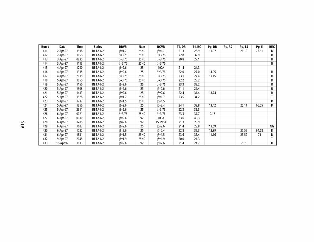
Run # Date Time Series DRVR Nozz RCVR T1, DR T1, RC Pp, DR Pp, RC Pp, T3 Pp, E REC411 2-Apr-97 1538 BETA-N2 β=1.7 25ND β=1.7 21.3 28.9 11.97 26.19 73.51 D412 2-Apr-97 1655 BETA-N2 β=3.76 25ND β=3.76 22.8 32.9 B413 3-Apr-97 0835 BETA-N2 β=3.76 25ND β=3.76 20.8 27.1 B414 3-Apr-97 1113 BETA-N2 β=3.76 25ND β=3.76 B415 4-Apr-97 1740 BETA-N2 β=2.6 25 100A 21.4 24.3416 4-Apr-97 1935 BETA-N2 β=2.6 25 β=3.76 22.0 27.0 14.05 B417 4-Apr-97 2035 BETA-N2 β=3.76 25ND β=3.76 23.1 27.4 11.45 B418 5-Apr-97 1055 BETA-N2 β=3.76 25ND β=3.76 22.2 29.2 B419 5-Apr-97 1150 BETA-N2 β=2.6 25 β=3.76 23.3 32.2 B420 5-Apr-97 1308 BETA-N2 β=2.6 25 β=2.6 21.1 27.4 B421 5-Apr-97 1413 BETA-N2 β=2.6 25 β=2.6 22.4 31.4 13.74 B422 5-Apr-97 1528 BETA-N2 β=1.7 25ND β=1.7 23.5 34.2 T423 5-Apr-97 1737 BETA-N2 β=1.5 25ND β=1.5 D424 5-Apr-97 1850 BETA-N2 β=2.6 25 β=2.4 24.1 39.8 13.42 25.11 66.55 D425 5-Apr-97 2311 BETA-N2 β=2.6 25 β=3.76 22.3 35.3426 6-Apr-97 0021 BETA-N2 β=3.76 25ND β=3.76 23.3 37.7 9.17427 6-Apr-97 0130 BETA-N2 β=2.6 92 100A 23.6 40.3428 6-Apr-97 1205 BETA-N2 β=2.6 92 15H/85A 21.3 29.9429 6-Apr-97 1607 BETA-N2 β=2.6 25 β=2.6 21.4 28.8 13.69 NG430 6-Apr-97 1722 BETA-N2 β=2.6 25 β=2.4 22.8 32.3 13.89 25.52 64.68 D431 6-Apr-97 1831 BETA-N2 β=1.5 25ND β=1.5 23.6 35.4 11.66 25.59 71 D432 9-Apr-97 2045 BETA-N2 β=1.9 25ND β=1.9 20.0 21.3 T433 16-Apr-97 1813 BETA-N2 β=2.6 92 β=2.6 21.4 24.7 25.5 D
���

���

Appendix E
RPI Jet Visualization
This Appendix contains photographs of jet startup from the �nal tests in the RPI facility�In the photographs� the diameter of the jet tube is ���� ��� mm�� The initial drivermixture is �� H���� O�� The receiver mixtures are listed in the captions�

�t��� ������ ms�
� ���� ms� �� ���� ms�
� ������ ms� �� ������ ms�
Figure E�� Jet startup� venting into ��� N�� Note lead shocks and large� turbulentvortex head which convects downstream� Framing rate is ���� kfps� RPI run �
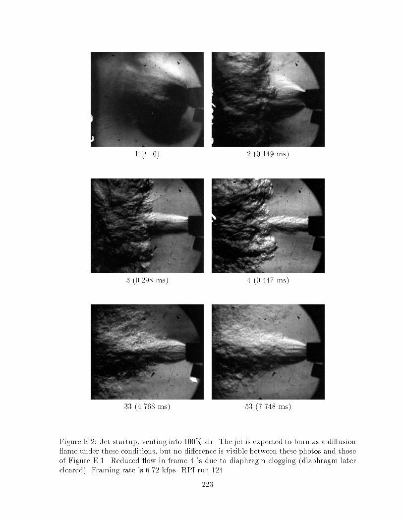
�t��� ����� ms�
� ���� ms� � ������ ms�
�� ����� ms� �� ����� ms�
Figure E�� Jet startup� venting into ��� air� The jet is expected to burn as a di�usion�ame under these conditions� but no di�erence is visible between these photos and thoseof Figure E�� Reduced �ow in frame � is due to diaphragm clogging �diaphragm latercleared�� Framing rate is ��� kfps� RPI run ��
�
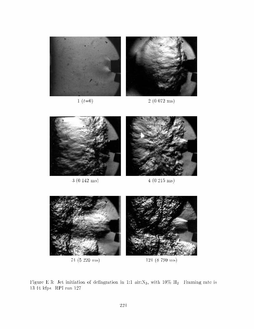
�t��� ����� ms�
� ���� ms� � ���� ms�
�� ���� ms� � � ���� ms�
Figure E��� Jet initiation of de�agration in � air�N�� with �� H�� Framing rate is���� kfps� RPI run ��
�