Embed Size (px)
Citation preview

→ Expert edition
Furnace atmospheres no. 1.
Gas carburising and carbonitriding.

02 Gas carburising and carbonitriding
1. Gas carburising and carbonitriding 2. Neutral hardening and annealing3. Gas nitriding and nitrocarburising4. Brazing of metals5. Low pressure carburising and high pressure gas quenching6. Sintering of steels
Preface.
This expert edition is part of a series on process application technology and know-how available from Linde Gas. It describes findings in development and research as well as extensive process knowledge gained through numerous customer installations around the world. The focus is on the use and control of furnace atmospheres; however a brief introduction is also provided for each process.

03Gas carburising and carbonitriding
Passion for innovation.
With R&D centres in Europe, North America and China, Linde Gas is leading the way in the development of state-of-the-art application technologies. In these R&D centres, Linde's much valued experts are working closely together with great access to a broad spectrum of technology platforms in order to provide the next generation of atmosphere supply and control functionality for furnaces in heat treatment processes. As Linde is a trusted partner to many companies in the heat treatment industry, our research and development goals and activities are inspired by market and customer insights and industry trends and challenges. The expert editions on various heat treatment processes reflect the latest developments.
More Information? Contact Us!Linde AG, Gases Division, Carl-von-Linde-Strasse 25, 85716 Unterschleissheim, Germany
[email protected], www.heattreatment.linde.com, www.linde.com, www.linde-gas.com
Linde Gas Research Centre Unterschleissheim, Germany.

Gas carburising and carbonitriding04
Contents.
Preface. 2
Passion for innovation 3
1. Introduction 6
2. Process 7
2.1 Basic principles 72.2 Steel properties 9
3. Furnace and equipment 14
3.1 Furnaces 143.2 Atmosphere equipment 163.2.1 High-speed gas injection for improved gas homogeneity 163.2.2 Methanol injectors and pumps 173.2.3 Sample gas handling 17
4. Atmosphere generation, gas supply 18
4.1 Carburising atmospheres 184.1.2 Endogas 204.1.3 Other carburising atmospheres 214.2 Gas and methanol supply 214.2.1 Nitrogen supply 214.2.2 Methanol supply 234.2.3 Supply of other gases 234.2.4 Flow and composition control 23

Gas carburising and carbonitriding 05
5. Atmosphere control 26
5.1 Theory and principles 265.1.1 Carbon mass transfer and chemical equilibrium 265.1.2 Nitrogen mass transfer and chemical equilibrium 285.1.3 Carbon potential control 295.1.4 Single step or boost carburising 315.1.5 Carbon and nitrogen control during carbonitriding 325.1.6 Internal oxidation 335.1.7 Hydrogen pickup 335.1.8 Surface passivation 345.1.9 Gas analysis 345.1.9.1 Gas analysis with IR 345.1.9.2 Oxygen probe 355.2 Automatic atmosphere composition control 35
6. Safety 38
6.1 Safety awareness 386.2 Gases used in the process 386.3 Potential safety hazards and their sources 386.3.1 Explosions/flammability/fire 396.3.2 Toxicity and asphyxiation 406.3.3 Cold burn hazards 406.3.4 Pressurised piping and the gas expansion hazard 406.4 Control of safety hazards 406.4.1 General safety regulations and guidelines 406.4.2 Explosions/flammability/fire 406.5 Safe use of gases along the value chain 41
References 42

Gas carburising and carbonitriding06
In order to achieve specific properties and the desired surface quality after heat treatment of a steel object, numerous process parameters need to be controlled. A most critical parameter is the composition, function and control of the furnace atmosphere. In carburising/carbonitriding processes, the function of the atmosphere is to supply the necessary amount of carbon (and nitrogen) and to provide the right carbon (and nitrogen) content to the steel surface, and this is what determines the final properties of the carburised object. Therefore, it is important to ensure a reliable supply of required gases and process gas blends but also to integrate leading application technologies to enable precision control of furnace atmospheres and ultimately achieve the desired product specifications of steels.
The purpose of this expert edition is to deliver a comprehensive technical overview of carburising and carbonitriding processes with critical influencing parameters in terms of the required equipment and furnace atmosphere. This expert edition should deliver valuable background information on a complex topic in a structured single document in order to achieve a higher confidence level in the readers’ business decisions.
Each of the expert editions has a similar content structure. The first part focuses on the process, explaining the basic principles of the hardness and carbon content of steels as well as the properties of carburised steels. The next section focuses on the different types of furnaces and the required equipment in the process. The furnace atmosphere generation and required gas supply is highlighted in the fourth section; the interaction between furnace atmosphere and steel surface and how to control the atmosphere is described in the fifth section. As flammable, asphyxiating and toxic gases are used in carburising and carbonitriding processes, safety issues need to be addressed in the sixth section; this is an important concern of Linde Gas.
1. Introduction.
Gas carburising and carbonitriding 07
2.1 Basic principles
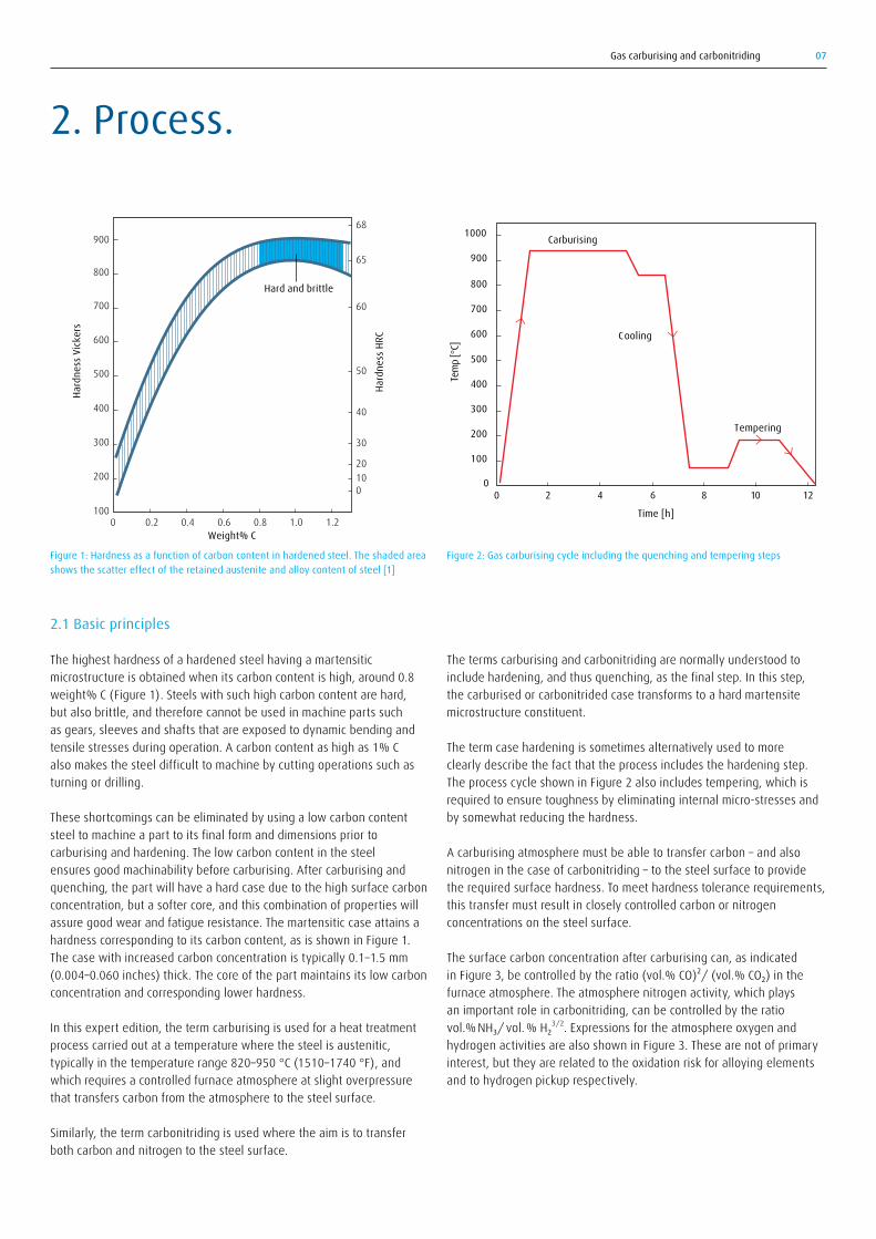
The highest hardness of a hardened steel having a martensitic microstructure is obtained when its carbon content is high, around 0.8 weight% C (Figure 1). Steels with such high carbon content are hard, but also brittle, and therefore cannot be used in machine parts such as gears, sleeves and shafts that are exposed to dynamic bending and tensile stresses during operation. A carbon content as high as 1% C also makes the steel difficult to machine by cutting operations such as turning or drilling.
These shortcomings can be eliminated by using a low carbon content steel to machine a part to its final form and dimensions prior to carburising and hardening. The low carbon content in the steel ensures good machinability before carburising. After carburising and quenching, the part will have a hard case due to the high surface carbon concentration, but a softer core, and this combination of properties will assure good wear and fatigue resistance. The martensitic case attains a hardness corresponding to its carbon content, as is shown in Figure 1. The case with increased carbon concentration is typically 0.1–1.5 mm (0.004–0.060 inches) thick. The core of the part maintains its low carbon concentration and corresponding lower hardness.
In this expert edition, the term carburising is used for a heat treatment process carried out at a temperature where the steel is austenitic, typically in the temperature range 820–950 °C (1510–1740 °F), and which requires a controlled furnace atmosphere at slight overpressure that transfers carbon from the atmosphere to the steel surface.
Similarly, the term carbonitriding is used where the aim is to transfer both carbon and nitrogen to the steel surface.
The terms carburising and carbonitriding are normally understood to include hardening, and thus quenching, as the final step. In this step, the carburised or carbonitrided case transforms to a hard martensite microstructure constituent.
The term case hardening is sometimes alternatively used to more clearly describe the fact that the process includes the hardening step. The process cycle shown in Figure 2 also includes tempering, which is required to ensure toughness by eliminating internal micro-stresses and by somewhat reducing the hardness.
A carburising atmosphere must be able to transfer carbon – and also nitrogen in the case of carbonitriding – to the steel surface to provide the required surface hardness. To meet hardness tolerance requirements, this transfer must result in closely controlled carbon or nitrogen concentrations on the steel surface.
The surface carbon concentration after carburising can, as indicated in Figure 3, be controlled by the ratio (vol.% CO)²/ (vol.% CO₂) in the furnace atmosphere. The atmosphere nitrogen activity, which plays an important role in carbonitriding, can be controlled by the ratio vol.% NH₃/ vol. % H₂3/2. Expressions for the atmosphere oxygen and hydrogen activities are also shown in Figure 3. These are not of primary interest, but they are related to the oxidation risk for alloying elements and to hydrogen pickup respectively.
2. Process.
Figure 2: Gas carburising cycle including the quenching and tempering stepsFigure 1: Hardness as a function of carbon content in hardened steel. The shaded area shows the scatter effect of the retained austenite and alloy content of steel [1]
100
200
300
400
500
600
700
800
Weight% C
Hard
ness
Vic
kers
Hard
ness
HRC
01020
30
40
50
60
65
68900
0 0.2 0.4 0.6 0.8 1.0 1.2
Hard and brittle
Tem
p [°
C]
Carburising
Cooling
Tempering
Time [h]
0 2 4 106 80
100
200
300
400
500
600
700
800
900
12
1000

Gas carburising and carbonitriding08
The process of carbonitriding is principally performed in the same way as carburising, only with the difference that both carbon and nitrogen are transferred from the gas to the steel surface. Nitrogen acts in the same way as carbon to increase the hardness of the hardened steel.
Carburising and carbonitriding are carried out on parts subjected to high fatigue stresses or wear, such as parts for transmissions, car engines, roller and ball bearings, rock drill parts, etc. Automobile manufacturers and their sub-suppliers are key examples of industries that have carburising and carbonitriding as steps in their manufacturing processes.
Low pressure carburising – commonly called vacuum carburising – is not described in this expert edition; however, a detailed description is given in reference [2]. Pack carburising and liquid drip feed carburising are rarely used alternatives that are not described in this edition.
After carburising, quenching is mostly carried out using mineral oils. An alternative, mainly used in vacuum carburising, is gas quenching, but there have also been initiatives to apply gas quenching to atmospheric pressure carburising.
The process of carburising is as follows: Ready-machined parts that are to be carburised, for instance gears, are placed in baskets or mounted (hung) on some type of fixture (see Figure 4), which is then loaded into a furnace. This will typically be at a temperature of 820–880 °C (1508–1616 °F) for carbonitriding and 900–950 °C (1652–1742 °F) for gas carburising. When the charge has reached carburising temperature, the effective transfer of carbon from gas to steel surface begins. Carburising is allowed to proceed until the desired depth of carbon penetration is reached. The charge is then moved from the heating chamber to a cooling chamber that is either integrated as a part of the furnace or is in the form of separate cooling bath equipment. There the load is rapidly quenched, often in a quench oil bath, but for separate cooling baths it could also be water-miscible polymer quenching media or salt. After cooling, the charge normally undergoes washing and tempering. The quenching process is important both in order to achieve the correct hardness and also to minimise distortions. Sub-zero treatment is sometimes used as a post process after carburising and quenching to increase hardness. The principles for quenching and sub-zero treatment are not described further in this expert edition. Dimension-adjusting grinding is normally required before the parts are completely finished.
P 2CO
PCO2
P · PCOPH O2
PCO
PO2
H2
P2CO
PCO PH2
PO2PH O2
Carbon activity
Oxygen activity
P3NH
PH2
PN2Nitrogen activity 3/2
PH2Hydrogen activity
or or
or or
or
Figure 3: Schematic illustration of atmosphere/metal interaction and expressions for proportionality between atmosphere composition and carbon and nitrogen activities. P is the partial pressure, which at atmospheric pressure is equal to vol.% divided by 100
Figure 4: Example of charging equipment (Courtesy of Ipsen International GmbH)
N2
CH4
CO H O2
C H3 8
H
O
N
C
H2
O2
CO2NH3
MetalGas/surfaceGas

Gas carburising and carbonitriding 09
The maximum surface hardness after carbonitriding depends on both the carbon and nitrogen surface concentrations. These concentrations are typically in the range 0.6–0.9% C and 0.2–0.4% N. An approximate guideline is that martensite with the same total concentration of the interstitial elements carbon and nitrogen has about the same hardness, irrespective of the relative proportions of the elements carbon and nitrogen.
Table 1. Surface carbon concentration for maximum surface hardness for some types of case hardening steels [5]
Major alloy elements Carbon Surface concentration [%C] hardness [HV]Ni (1–4%) 0.60–0.75 620–6701.5% Cr, 2% Ni, 0.2% Mo 0.65–0.70 8401.5% Mn, 0.004% B 0.85 815Mn, Cr 0.70 840Mo, Cr 1.0 940
In the following section, we focus on case hardened depth, often shortened to just case depth, and carburising depth. The case hardened depth (CHD) is defined as the depth from the surface to the point where the hardness is 550 HV, as shown in Figure 6. Sometimes a hardness other than 550 HV is used to define the case depth.
The attained case depth depends not only on carburising depth, but also on the hardening temperature, the quench rate, the hardenability of the steel and the dimensions of the part. This is illustrated in the schematic Continuous cooling transformation (CCT) diagrams in Figure 7. (For a detailed description of hardenability and CCT diagrams, see reference [5].) The hyperbolic temperature/time-dependent parts of the transformation curves depict the transformation from austenite to ferrite/pearlite. For a high hardenability steel, these curves are located
2.2 Steel properties
The gas-carburised (carbonitrided) part can be said to consist of a composite material, where the carburised surface is hard but the unaffected core is softer and ductile. Compressive residual stresses are formed in the surface layer upon quenching from the carburising temperature. The combination of high hardness and compressive stresses, as seen in Figure 5, results in high fatigue strength, wear resistance, and toughness.
Maximum hardness after hardening for unalloyed steels is obtained when the carbon concentration is about 0.8% C, as was shown in Figure 1. Above that carbon concentration, the hardness decreases as the result of an increased amount of retained austenite. The hardness curve therefore often exhibits a drop in hardness close to the surface, where the carbon concentration is highest. Carbon, nitrogen and almost all alloying elements lower the Ms-temperature. After carburising and quenching, there will therefore be a retained austenite concentration gradient that increases towards the surface. To compensate for this effect, the surface carbon concentration after carburising that provides maximum surface hardness has to be lowered as the alloy content of the steel increases.
Carbide-forming elements, such as chromium and molybdenum, can counteract this effect and raise the surface carbon concentration that provides maximum hardness. This is because the formation of carbides leads to a lowered carbon concentration in the austenite, although the average carbon concentration is high.
Table 1 gives some examples of the relationship between maximum hardness and carbon surface concentration for different types of steels. Mo-alloyed steels obtain the highest surface hardness and Ni-alloyed steels the lowest. Mn-Cr steels obtain an intermediate surface hardness.
1000
900
800
700
600
500
400
300
200
100
0
1.0
0.9
0.8
0.7
0.6
0.5
0.4
0.3
0.2
0.1
0
–100
–200
–300
–400
N/mm2 %C HV
Hardness
Carbon content
Residual stress
0.1 0.3 0.5 0.7 0.9 1.1
Depth [mm]
550
CHD
Depth from surface [mm]
HV
Figure 5: Typical hardness, carbon content and residual stress gradients after carburising, quenching and tempering
Figure 6: Definition of case depth [4]

Gas carburising and carbonitriding10
The hardenability of steel number 1 in Figure 7b is too low to result in martensite transformation even for the carburised case. As shown in Figure 7c, carbonitriding is a method for achieving high enough hardenability to form a martensitic case. (The “surface” cooling line passes to the left of the carbonitrided transformation curve.) Carbonitriding is a way to make water-quench (polymer quenching media) steels become oil hardening steels.
Figure 7d schematically shows the effect of part dimensions on cooling rate. The bigger the dimensions, the slower the cooling rate. Therefore, there is a certain maximum diameter for a certain steel grade that can be hardened to form a martensitic case. When a martensitic case is formed, the case depth will decrease with increasing diameter, as shown in Figure 8.
far to the right in the diagram, ensuring that the cooling curves do not cross the ferrite/pearlite transformation curve. Hardenability increases not only with base steel alloy content but also with increased carbon and nitrogen concentrations. The carburised or carbonitrided case therefore has higher hardenability than the base steel. Some examples of how different parameters will affect hardenability are described in relation to Figure 7 in the following.
In Figure 7a, the cooling curves for both “surface” and “centre” cross the transformation line for the base steel, the core. This means that the core will transform to ferrite/pearlite upon cooling from hardening temperature. If the cooling curves are related to the “case” instead, it can be seen that the cooling line for the surface passes to the left of the ferrite/pearlite transformation curve. Thus the “surface” cooling line first crosses the Ms (case) line, meaning that the austenite will transform to martensite, as is the intention in case hardening.
CoreCarburised case
Ms (core)
Ms (case)
Core
Time
Surface
Steel no 1low hardenability
Steel no 2high hardenability
Ms (core)
Ms (case)
Core
TimeTe
mpe
ratu
re [°
C]Te
mpe
ratu
re [°
C]
Surface
Carburised caseCarbonitrided case
Ms (core)
Ms (case)
Core
Time
Surface
Ms (case)
Large diameter
Time
Small diameter
Tem
pera
ture
[°C]
Tem
pera
ture
[°C]
a. Same steel but different core and carburised case hardenability b. Two steels with different case hardenabilities
c. Case hardenability after carburising and carbonitriding respectively d. For the same quench severity the cooling rate decreases with increased part dimensions
CoreCarburised case
Ms (core)
Ms (case)
Core
Time
Surface
Steel no 1low hardenability
Steel no 2high hardenability
Ms (core)
Ms (case)
Core
TimeTe
mpe
ratu
re [°
C]Te
mpe
ratu
re [°
C]
Surface
Carburised caseCarbonitrided case
Ms (core)
Ms (case)
Core
Time
Surface
Ms (case)
Large diameter
Time
Small diameter
Tem
pera
ture
[°C]
Tem
pera
ture
[°C]
Figure 7: The relationship between the cooling rate of the surface and of the centre to the hardenability of the carburised case and unaffected core. a. The hardenability of the carburised case, resulting in martensite formation, is higher than for the non-carburised core that transforms to pearlite. b. Upon hardening, the case of steel number 2 will transform to martensite, whereas the case of steel number 1 will be pearlitic. c. The carbonitrided case will transform to martensite, whereas the carburised case will transform to pearlite. d. The small diameter cools faster, resulting in a martensitic case, whereas the larger diameter will have a pearlitic case

Gas carburising and carbonitriding 11
Carburising depth is not standardised but is nevertheless used in practice, and is defined as the depth from the surface to the point corresponding to a specified carbon concentration. As a guideline, the CHD for common steels and part dimensions is approximately equal to the carburising depth to the point where the carbon concentration is about 0.35% C (see Figure 1). The carburising depth depends on treatment time and temperature. With prolonged carburising time, carbon can diffuse to a greater depth into the steel. Increasing the temperature increases the rate of diffusion and thus increases the carburising depth. This is illustrated in Figure 9.
Carburising depth for a carburising time of 0–1.6 hours
0
0.1
0.2
0.3
0.4
0.5
0.6
0.7
0.8
0.9
0 0.2 0.4 0.6 0.8 1.0 1.2 1.4 1.6
1030 °C (1886 °F)
980°C (1796 °F)
930°C (1706 °F)
880°C (1616 °F)
Time [h]
Dept
h to
0.3
%C
[mm
]
0
0.5
1.0
0 5 10 15 20 25 30 35
1.5
2.0
2.5
3.0
3.5
1030 °C (1886 °F) 980°C
(1796 °F)
930°C (1706 °F)
880°C (1616 °F)
Time [h]
Dept
h to
0.3
%C
[mm
]
Carburising depth for a carburising time of 0–25 hours
Figure 9: Approximate relationship between temperature, time and carburising depth to 0.3%C: Curves are calculated for the following conditions: steel 16MnCr5, carbon potential 0.8%C, atmosphere 40% nitrogen/60% cracked methanol. No account is taken of heating-up time or time for atmosphere conditioning
0 0.4 0.8 1.2 1.60.2 0.6 1.0 1.4 1.8300
400
500
600
700
800
900
Hard
ness
, HV
Depth below the surface [mm]
Diameter [mm] 145 100 50
10
Figure 8: An example of how case depth depends on dimensions [7]
Carbonitriding often yields carburising depths that are somewhat greater than those for pure carburising. It is an effect caused by the interaction with respect to diffusivity between carbon and nitrogen.
The proper case depth requirements are determined by the surface load, wear conditions, and static and bending fatigue stresses that the finished part will be subjected to in its service life. A limiting factor is the cost of the required process time, which, as Figure 9 shows, increases in a parabolic manner as carburising depth increases. Some guidelines for case depth specifications are given in Table 2.

Gas carburising and carbonitriding12
The following section deals with steels for carburising and carbonitriding. When selecting the steel type, the first requirement is that the alloy and carbon concentration meet the requirements for the resulting core hardness after austenitising, quenching and tempering. For specific core hardness requirements, this means that as the dimensions of the treated parts increase, the required alloy content will also increase. The hardenability of a case hardening steel must be sufficiently good to result in a martensitic surface case to the required depth. Case hardening steels must therefore contain a certain amount of alloying elements. A further requirement is that steels for carburising should be fine grain treated. This means that the steel should contain an alloy element, usually aluminium, that creates fine precipitates. These precipitates act as barriers to grain growth up to a certain maximum temperature, typically about 950 °C (1742 °F). Examples of some standardised carburising steels are given in Table 3.
Distortion after carburising and quenching normally results in the part dimensions not meeting the specified tolerances. The carburising depth must therefore be sufficient to attain the final specified case or carburising depth after grinding. Grinding allowance is typically of the order of 0.1–0.2 mm.
Core hardness is not affected by the carburising process itself but depends only on the type of steel and its carbon content, hardenability, part dimensions and quenching severity. The best fatigue resistance both for gears and parts subjected to bending fatigue is obtained with a core hardness in the range 400–450 HV [3].
There is interdependence between case and core as regards residual stresses. The amplitude of the compressive residual stresses in the case is lowered as core strength increases.
Table 2. Simple rules for selection of case depth
Type of partParts subjected to surface fatigue
GearThin partsParts subjected to surface loads
Case depth
Potentialfailure zone
Fatigue strength
1 2 3
1. Shallow case2. Optimum case3. Deep case
Applied stressDistance from surface
Stre
ss
CHD = 0.15 to 0.20 times the gear moduleCHD < 0.2 × thicknessCHD = 3 to 4 times the depth to maximum stress
RemarkThe case depth shall be deep enough to avoid failure initiated below the surface.
For optimum fatigue lifeTo prevent through-hardening

Gas carburising and carbonitriding 13
Table 3. Composition of selected steel types that can be carburised and hardened
European Steel USA ASTM Steel Chemical compositionDesignation16MnCr516MnCrS520MnCr520MnCr S518CrMo418CrMoS416NiCr416NiCrS420NiCrMoS2-217NiCrMo6-417NiCrMoS6-4
Designation511751175120/5120H5120/5120H4118/4118H5120/5120H8620
8620/8620H
AISI 4317
% C0.14–0.190.14–0.190.17–0.220.17–0.220.15–0.210.15–0.210.13–0.190.13–0.190.17–0.230.14–0.200.14–0.20
% Mn1.00–1.301.00–1.301.10–1.401.10–1.400.60–0.900.60–0.900.70–1.000.70–1.000.65–0.950.60–0.900.60–0.90
% S<0.0350.020–0.040<0.0350.020–0.040<0.0350.020–0.040<0.0350.020–0.0400.020–0.040<0.0350.020–0.040
% Cr0.80–1.100.80–1.101.00–1.301.00–1.300.90–1.200.90–1.200.60–1.000.60–1.000.35–0.700.80–1.100.80–1.10
% Mo
0.15–0.250.15–0.25
0.15–0.250.15–0.250.15–0.25
% Ni
0.80–1.100.80–1.100.40–0.701.20–1.501.20–1.50
Carbonitriding can be applied to low-cost, low-alloy steels. The combination of adding nitrogen as well as carbon to the case increases the case hardenability sufficiently to result in a martensitic case that
would not be possible with pure carburising. A few examples of steel types suitable for carbonitriding are given in Table 4.
Table 4. Composition of some steel types that can be carbonitrided
Steel typeSteel for cold–rolled stripFree–cutting steels
General constructional steel
% C0.07max 0.14max 0.140.12–0.180.12–0.18max 0.5
% Simax 0.30max 0.05max 0.050.18–0.400.10–0.40(1.0–1.6)
% Mn0.25–0.450.90–1.300.90–1.300.80–1.200.80–1.20max 0.05
% Pmax 0.030max 0.11max 0.11max 0.06max 0.06max 0.05
% Smax 0.0400.24–0.350.24–0.350.15–0.250.15–0.25max 0.05
% Pb–0.15–0.350.15–0.35–0.15–0.35–
Some rare applications require carburising of high-alloy steels. The term excess carburising is used when such steels are carburised to surface carbon concentrations as high as 2–3% C. The aim is not just to produce a martensitic case but also to form high concentrations of carbides and of retained austenite, which has been shown to improve contact fatigue life, as illustrated in Figure 10.
3000
2000
1000800
600
400
4000
10 20 30 40 50 60Retained austenite [%]
L 10 LI
FE (×
104 )
Figure 10: Contact fatigue life of excess carburised steels [8]

Gas carburising and carbonitriding14
Cylindrical batch retort furnaces called pit furnaces are commonly used when long parts are to be gas carburised. As for the box furnace, the load must be transferred in air from the furnace to the separate quench baths.
In the automotive industry, continuous pusher-type furnaces are dominating for mass production of parts. The name of the furnace comes from the fact that the parts in such a furnace are loaded on trays that are pushed through the furnace, incorporating modules/stations for preheating, heating, carburising, diffusion, quenching, washing and tempering (see Figure 12).
For small parts like bolts, nuts, etc., the conveyor furnace is commonly used (see Figure 13). The parts are transported through the furnace on a movable conveyor. At the end of the conveyor, the parts fall vertically down into the quench bath. A second conveyor transports the quenched parts further for washing and tempering. Other examples of continuous hardening furnaces are shaker hearth and rotary retort furnaces that are used for small parts such as screws, bolts and nuts.
3.1 Furnaces
In the heat treatment industry, different furnace types exist. The main categories are batch furnaces and continuous furnaces, and they operate either with atmospheric pressure or under vacuum. Vacuum furnaces will not be described here but are covered for instance in reference [8]. In the following, the most relevant furnaces that are used for carburising and carbonitriding for the main target industries are presented.
In the batch furnace category, the sealed quench batch furnace shown in Figure 11 is commonly used within the metalworking industry. This furnace type is sometimes called multipurpose furnace because it can be used not only for carburising and carbonitriding but also for other processes such as hardening or nitrocarburising.
In this furnace, the heating chamber is separated from the quench chamber by an internal door. The parts are loaded in baskets or on fixtures, which are loaded into the heating chamber. (The furnace can be built with an additional separate loading chamber that has the function to minimise the disturbance of the atmosphere in the hot heating chamber upon loading.) After heating to austenitising temperature and when carburising is completed, the intermediate door between heating and quench chambers opens and the load is transferred down into the oil quench bath on an elevator.
Bottom-loaded bell-type furnace lines with integrated units for quenching are not so common but have advantages for carburising and hardening of long products.
Box furnaces with just one chamber are an alternative, but then with separate quench baths, the load has to be transferred in air from the furnace to the quench. A disadvantage with this arrangement is that oxidation of the surfaces will occur during the transfer in air.
3. Furnace and equipment.
Figure 11: Example of a sealed quench furnace line and charging equipment (left) and cross section of a sealed quench furnace showing the heat chamber and the integrated oil quench bath (right) (Courtesy of Ipsen International GmbH)
2
1
33
4
5
1 Basket (moves on chains), 2 Parts, 3 Fans for homogeneous atmosphere, 4 Heat treatment, 5 Oli bath (parts are quenched/cooled down)

Gas carburising and carbonitriding 15
Figure 12: Layout of a continuous carburising line with the pusher furnace in the centre
Figure 13: Conveyor furnace for hardening: cross section and installation (Courtesy of Safed, Fours Electrique Delmont S.A.)
Pre-oxidation/burning-off
HeatingDiffuse
Tempering
Quenchtank Wash
Carburise

Gas carburising and carbonitriding16
The system consists of one or several CARBOJET® lances with piping and flowtrain. The number of lances is adapted to the furnace size and the existing gas consumption. The lances can be controlled manually or through a CARBOFLEX® control unit. The specially designed lances are made of heat-resistant material to ensure a long lifetime. In order to provide tailor-made solutions, Linde Gas adapts its CARBOJET® systems to individual customer needs.
3.2 Atmosphere equipment
3.2.1 High-speed gas injection for improved gas homogeneityIt is essential that the furnace atmosphere is evenly mixed and circulated so that all part surfaces will experience the same carburising effect with respect to final carbon content and case depth. CARBOJET® high-speed gas injection is a patented technology by Linde Gas which allows for better gas convection in heat treatment furnaces without fans. By injecting the required amount of gas at high velocities into one or several positions of the furnace, CARBOJET® creates a movement in the furnace atmosphere to ensure homogeneous gas and temperature distribution. CARBOJET® can be installed in both continuous and batch furnaces for carburising and carbonitriding.
Figure 14: CARBOJET® high-speed gas injection
Figure 15: Examples of methanol injectors

Gas carburising and carbonitriding 17
Figure 16: Sample gas lance
This solution has proven to be very successful in continuous annealing furnaces [9] but also in carburising pit furnaces where significant savings in maintenance costs have been achieved, and a more homogeneous product quality and reduced soot formation have been established [10]. The lances are practically maintenance-free; furnaces where fans have been replaced by the CARBOJET™ high-speed injection system can therefore be operated for longer without shutdowns. Shutdowns caused by broken fans and disturbances of vibrating fans are completely eliminated. This leads to the additional advantage that the heating elements, retorts and brick lining will suffer less frequent damage.
In summary, the advantages of the high-speed gas injector are:• homogenised product quality • no fans are needed, maintenance-free technology• increased utilisation of carburising gases and reduced soot formation
in heat treatment furnaces. The high-speed injection of gases also optimises the functionality of analysing equipment due to better gas mixing
• increased carbon transfer on material surfaces due to forced convection of the atmosphere.
3.2.2 Methanol injectors and pumpsThe theoretical principles for using cracked methanol as a source for creating the carburising atmosphere is described in the next section. The specially designed methanol injectors seen in Figure 15 are integrated parts of the CARBOTHAN® system.
The methanol pump is another integrated part of the CARBOTHAN® system. To ensure steady supply, a double pump system is recommended. The gear pump has proven to be an adequate type of pump. It has to fulfil safety regulations.
3.2.3 Sample gas handlingIt is most important that the sample gas is drawn from the furnace in a way that ensures that a representative furnace atmosphere sample is analysed. Figure 16 shows an example of a gas lance design that meets this requirement. It has an outer protective tube and a ceramic inner sample gas tube. The design is intended to avoid thermal stresses due to different thermal elongations of the metallic and ceramic tubes. There is a pin at the end of the lance that in case of a crack in the ceramic tube will obstruct it from falling into the furnace.

Gas carburising and carbonitriding18
The two main methods to produce carburising atmospheres are: 1) dissociated methanol + nitrogen or 2) endogas. To a limited extent other alcohols, such as ethanol, or carbonaceous liquids, such as acetone, have been used. However, these alternatives lead to a lower atmosphere quality that results for instance in soot problems and will therefore not be further described here.
4.1.1 Nitrogen/methanol atmospheres
A common carburising atmosphere is a mixture of nitrogen and methanol that is introduced directly into the furnace chamber. Upon entering the furnace, methanol dissociates to form carbon monoxide and hydrogen in accordance with the following reaction:
CH₃OH → CO + 2H₂
As shown in Figure 18, complete cracking of methanol into CO and H₂ only occurs if the temperature is above 800°C (1472°F), which is why methanol should not be introduced into a furnace at a lower temperature. If cracking occurs at too low a temperature, there will be a risk of soot formation.
For every litre of methanol that is added, approximately 1.7 m³ of gas is formed, consisting of one volumetric part CO and two parts of H₂. Different gas compositions are obtained by varying the mixing ratio between nitrogen and methanol. A mixture of 40% nitrogen (N₂) and 60% dissociated methanol is used to generate an atmosphere that is similar to an endogas atmosphere.
Linde Gas has installed hundreds of nitrogen/methanol systems in several markets under the trademark CARBOTHAN™ in sealed quench furnaces used both for hardening and for carburising with the principal design shown in Figure 19.
4.1 Carburising atmospheres
There are a number of possible options to produce an atmosphere for carburising. Naturally, the atmosphere must have a carbon source, which could be carbon monoxide, a hydrocarbon, an alcohol or any other liquid carbon source. However, to obtain a high quality controllable carbon atmosphere, the options are limited to atmospheres that contain carbon monoxide and hydrogen in order to result in carburising according to the illustration in Figure 17. This is because atmosphere carbon control based on the principles for thermochemical equilibrium is possible only for such atmospheres (see further explanations in Section 5). The chemical reaction formula in the figure shows that carbon monoxide (CO) reacts with hydrogen (H₂), thereby producing a carbon (C) atom that is deposited at the steel surface, and water vapour (H₂O) that is left in the atmosphere. C is underlined in the reaction formula; this is common practice to signify that carbon is in solid solution in the steel.
In addition, a certain part of the atmosphere mostly consists of nitrogen, which acts as a carrier for the active carburising gases. Nitrogen also dilutes the concentrations of the active and flammable gases to minimise flames and the risk of soot deposits. Nitrogen also ensures safety. The atmosphere part that consists of nitrogen, carbon monoxide and hydrogen (N₂+CO+H₂) is often called the “carrier gas”.
To control the atmosphere carbon potential, an “enriching gas” is also needed. The enriching gas is a hydrocarbon, for increasing the carbon potential. It is normally supplied automatically in small quantity with just the necessary amount required to maintain the atmosphere carbon potential. Sometimes air is added to decrease the carbon potential. For carbonitriding, ammonia is additionally required.
4. Atmosphere generation, gas supply.
H
CO
2
H O2
CO + H C + H O22
C
Figure 17: Schematic illustration of the carburising process
Figure 18: Resulting gas composition upon cracking of methanol in an atmosphere containing 40% nitrogen and 60% cracked methanol
10
20
30
40
vol%
400 500 600 700 800 900 10000
CO2
C
CH4 H
2 O
CO
H 2
°C

Gas carburising and carbonitriding 19
The cracking of methanol can be improved by disintegrating the liquid methanol stream into droplets. This can be accomplished by introducing the methanol into the fan area of the furnace, as shown in Figure 20. This has the advantage that the liquid methanol is dispersed by the fan and is therefore correctly vaporised and dissociated into carbon monoxide (CO) and hydrogen (H₂). Another way is to use a special atomising spray nozzle.
Assurance of safety is an important aspect that has to be integrated into the system.
When introducing methanol, it is important that the time for the liquid methanol to pass the temperature interval of 250–700 °C (482–1292 °F) is as short as possible. Below 250 °C (482 °F), the methanol will not readily crack but will vaporise. Furnace regions at that temperature can in some cases successfully be used for vaporising methanol.
The cracking of methanol into CO and H₂ requires energy. This energy is taken from the area surrounding the point of methanol injection. There must therefore be sufficient heat flux towards the injection point to ensure proper dissociation. A conveyor furnace typically has a low height Figure 20: Methanol injection into the fan area of a furnace
Figure 19: Nitrogen/methanol system
Furnace
Liquid methanol
Actual value
Setpoint value
Setpointvalue
Actualvalue% °C
Control systemLiquidnitrogen
CyHx
Air
Vaporiser
Methanol tank
Temp
Pump
a. CARBOTHAN® lance CTL1
b. CARBOTHAN® lance CTL4

Gas carburising and carbonitriding20
4.1.2 EndogasEndogas is produced by incomplete combustion of hydrocarbons with air in accordance with one of the reactions:
C₃H₈ + 7.2 air → 5.7 N₂ + 3CO + 4H₂
CH₄ + 2.4 air → 1.9 N₂ + CO + 2H₂
As is evident from these reaction formulas, gas compositions will be somewhat different depending on the hydrocarbon used for endogas production (see Table 5). The atmosphere compositions for the minor constituents CO₂, CH₄ and H₂O given in the table will change when the gas enters the hot furnace as a result of the reaction with air and oil vapours that are present, and because a new chemical equilibrium composition will be established determined by the furnace temperature itself. However, the concentrations of the major constituents N₂, CO and H₂ will not change to any notable degree.
The mixing and combustion of fuel and air take place in special endothermic gas generators, see schematic in Figure 22.
The output flow rate from the endogas generator can only vary within a very small band, and the gas composition is almost set but not quite. Endogas is a reducing atmosphere with a controllable carbon concentration.
and a restricted cross section. It is a poor solution to inject methanol as liquid into the interior of such a furnace. The reason is the risk of creating a cold spot at the point of injection, because methanol dissociation requires energy, which is taken from the limited surrounding volume. This results in a locally decreased temperature. Negative consequences can be deposits of soot at the point of injection. A better solution is to use a vaporiser for methanol, in which methanol is vaporised before entering the furnace. Upon vaporising, there is a volume increase of approximately a factor of 600. When entering the furnace, the vapour is spread into a wide space. The energy required for heating to furnace temperature and for dissociation of methanol is also taken from this wide space, resulting in a negligible temperature drop. Figure 21 shows an example of how such a methanol vaporiser is positioned at the rear furnace wall, just over the quench chute in a conveyor furnace.
For bell furnaces, it is also advantageous to have a separate methanol vaporiser as shown in Figure 21. A methanol vaporiser is a good solution in all cases where the methanol cracking occurs within a limited volume such as in small furnace rooms.
Injectors and gas inlets should be located away from exhaust gas outlets, sample gas outlets as well as away from any oxygen probe.
Figure 21: Examples of methanol vaporiser installations in a) a conveyor and b) a bell furnace
Figure 22: Schematic principles of the endogas generator
a. Methanol vaporiser mounted at the rear of a low height conveyor furnace
b. Methanol vaporiser mounted on the bottom of a bell furnace
Table 5. Typical atmosphere compositions for endogas based on hydrocarbons used
Hydrocarbon used Approximate volume % of atmosphere constituents
MethanePropane
N₂4045
H₂4032
CO2023
CO₂0.30.3
H₂O0.3–0.70.3–0.7
CH₄0.3–0.50.3–0.5
2.4 volume units of air, 1 volume unit of natural gas
Retort with Ni catalyst
Cooling
4.9 volume units of endogas

Gas carburising and carbonitriding 21
4.2 Gas and methanol supply
A nitrogen/methanol system for heat treatment is set up by media storage, flow control and distribution to furnaces, intake into furnace and atmosphere control (see Figure 19). The distribution to the furnace can be described as follows: The nitrogen leaves the storage tank at a medium pressure set on the tank. Inside the industrial premises, the pressure is reduced before the gas reaches the furnaces. Methanol is introduced into the piping system by means of a pump. Propane and ammonia are transported by the pressure in the storage vessels.
Regarding the intake into the furnace, the gaseous components in nitrogen-based systems are introduced in the same way as gas from other systems, that is, to ensure optimum mixing and circulation. However, for methanol, which is introduced in liquid form, a special technique is required which uses lances in order to ensure good vaporising and cracking (see Section 4.1.1) regardless of the type of furnace, location of intake, or whether a fan is used, and so on.
4.2.1 Nitrogen supplyJust pure nitrogen is used for purging upon start-up or shutdown. It is also used during idling when production is stopped, for instance in continuous carburising furnaces. In this way, good conditions are created for short atmosphere conditioning when starting production again. Nitrogen or carbon dioxide is also used for fire extinguishing. There are five major supply forms for nitrogen:
Gaseous nitrogen in cylinders: For cost reasons, this option is relevant only for very limited gas consumption.
4.1.3 Other carburising atmospheresThe fastest carbon transfer is achieved in an atmosphere consisting of equal parts of CO and H₂. It is technically feasible to create an oxidising reaction of a hydrocarbon that leads to a ratio of 1:1 between CO and H₂ by oxidising methane with CO₂ according to the reaction:
CH₄ + CO₂ → 2CO + 2H₂
Generating a reaction gas atmosphere with an optimum k' value in this way is more expensive than generating endothermic or nitrogen/methanol atmospheres. One reason for this is that the reaction between CH₄ and CO₂ to form CO and H₂ is extremely endothermic and therefore requires energy. It is therefore only worthwhile using gases of this kind if it is possible to achieve either lower costs due to increased productivity or improvements in quality. The absolute time saving increases with increased carburising depth, but the possible percentage reduction in carburising time is particularly significant for low carburising depths (see Figure 23). For a carburising depth of 0.1 mm, the time saving is close to 20%, but falls to about 5% for 1 mm depth. As seen in Figure 23, the absolute time-saving effect in minutes is greater at lower carburising temperatures. These benefits are best utilised in carburising small components (such as bolts or machine components) and thin-walled sheet metal parts to low carburising depths in continuous furnaces such as belt furnaces.
Figure 23, left: Calculated time saving in minutes as a function of carburising depth and temperature when comparing carburising in atmospheres containing 50% CO/50% H₂ to 20% CO/40% H₂ (40% N₂-60% cracked methanol). Right: Approximate relative time saving in % as a function of carburising depth. (The calculation was conducted for an atmosphere with 0.8% C carbon potential. Heating-up time and atmosphere conditioning time were omitted.)
5
0 0.1
10
15
20
25
30
35
0.2 0.3 0.4 0.5 0.6 0.7 0.8 0.9 1.00
980 °C (1796 °F)
930 °C (1706 °F)
880 °C (1616 °F)
Carburising depth to 0.3% C [mm]
Time
redu
ctio
n [m
in]
0
2
0.1
4
6
8
10
12
14
16
18
20
0.2 0.3 0.4 0.5 0.6 0.7 0.8 0.9 1.0Tim
e re
duct
ion
[%]
Carburising depth to 0.3% C [mm]

Gas carburising and carbonitriding22
Liquid nitrogen:The liquid nitrogen is supplied by truck to the customer container (see Figure 24). This is the most common supply method that is cost-efficient for a flow from 10 to 100–200 m³/h. Nitrogen supplied in the liquid form has a high purity, with typical contamination levels of O₂ + H₂O at 5 ppm. The liquid nitrogen is supplied by truck to the vacuum-insulated liquid nitrogen storage tank at the manufacturing plant. The liquid nitrogen supply form has the advantage that the amount of nitrogen supplied to the furnaces can be varied within wide limits. The customer takes only the amount needed at any time.
Nitrogen produced on-site with cryogenic technology:Cryogenic on-site production yields high-purity nitrogen, typically with 5 ppm oxygen and moisture content. It is relevant for flow rates from 250 to 1500–2000 m³/h.
Nitrogen produced on-site with adsorption technology:A PSA (Pressure Swing Adsorption) unit is installed on-site at the facility, Figure 24c. ECOVAR® is a family of on-site production units supplied by Linde Gas. Nitrogen produced using the PSA technique has a purity of 99 to 99.99%. Flow rates from 10 to 1500–2000 m³/h can be accommodated.
Nitrogen produced on-site with membrane technology:A membrane unit is installed on-site at the facility. Nitrogen produced with the membrane technique has a purity of about 99%, or differently expressed contains up to 1 vol.% oxygen. The cost for membrane nitrogen is lowered if a certain concentration of impurity oxygen can be accepted. A carburising atmosphere typically has 60 vol.% of the reducing species CO and H₂. A consequence of these high concentrations of reducing species is that the oxygen in the membrane nitrogen stream is reduced, for instance in the reaction
H₂+ ½O₂ → H₂O
thereby eliminating the risk of oxidation. Studies have shown that an oxygen concentration level of the order of 0.5–1.0 vol.% in the membrane nitrogen stream does not increase the risk of internal oxidation [11]. However, as the nitrogen should be available for purging in safety situations, the preferred maximum oxygen concentration level is 0.5 vol.%. Flow rates from 5 to 1000 m³/h can be accommodated.
The on-site production methods are normally combined with a liquid nitrogen tank supply. This extra supply is for back-up purposes and to meet instant needs of higher flow rates.
Figure 24: Nitrogen supply methods. a) Storage tank and vaporiser for liquid nitrogen. b) Cryogenic nitrogen production with CRYOSS®. c) PSA (Pressure Swing Adsorption); ADSOSS®.
a
b
c

Gas carburising and carbonitriding 23
4.2.3 Supply of other gasesOther gases necessary are:• Ammonia for carbonitriding• Hydrocarbons as enrichment gas
Propane and ammonia are usually delivered in cylinders or cylinder bundles, and in rare cases with large consumption in drums or tanks. Propane and ammonia liquefy at relatively low pressures. These gases are therefore also stored in liquid form. The feeding of gas is caused by the gas pressure over the liquid in the supply container. It means that the vaporising from liquid to gas must occur at a corresponding rate. With moderate gas consumption, this happens without any problem. If, however, the gas consumption is high, then the vaporising rate will not be high enough. In such cases, the vaporising rate will need to be increased. Installing a separate vaporiser is the most reliable method.
Carbon dioxide for fire extinguishing is supplied as compressed gas in cylinders.
4.2.4 Flow and composition controlThe atmosphere conditioning time upon start-up can be shortened by using a high purge gas flow rate as illustrated in Figure 26. The same principle can be utilised to shorten the time for changing from one atmosphere composition to another. Although not implemented in practice for carburising, one possible utilisation of this principle could be changing from high methanol (low nitrogen) to low methanol (high nitrogen) concentration.
4.2.2 Methanol supplyMethanol is stored in tanks of varying size depending on the rate of consumption. Small consumers fill their tanks from barrels, while large consumers fill them from road tankers. An example of a methanol tank installation is shown in Figure 25. Nitrogen inerting of the methanol storage is common both to ensure safety and to eliminate the risk of humidity entering into the methanol.
The methanol storage installation should be set up in accordance with local safety regulations. It could for instance mean that the tank has to be surrounded by a barrier or wall to eliminate the risk of spreading methanol spills. Due to the highly toxic nature of the gas, there may also be a locked entrance to the methanol storage area.
There are three different means of passing the methanol from the storage tank to the furnace. The first is by applying pressure to the nitrogen by pressurising the methanol storage tank with nitrogen. This method is straightforward but has the drawback that nitrogen may dissolve in the methanol, causing problems with gas bubbles and unsteady flow. The second method is by positioning the methanol container at such a high level that gravity will feed the methanol to the furnace. This method is for practical reasons limited to cases with small methanol containers. The third method is by using a pump to feed the methanol. For safety and process reliability purposes, Linde recommends the last method.
Figure 25: Methanol tank installation. The liquid nitrogen tank is seen in the background. Figure 26: Purging of a furnace with inert gas.
Impu
rity
O 2, CO
2, et
c. [%
]
Time
Low flow
High flow

Gas carburising and carbonitriding24
Another example of the benefit of flow control is the minimising of atmosphere disturbance from air entering the furnace chamber at door openings. By using a high flow rate at these door openings, disturbances are levelled out (see Figure 27a). Another case where high flow rate can minimise disturbances is upon quenching (see Figure 27b).
A high gas flow is desirable in the following cases:• at the beginning of a cycle when the furnace is originally air-filled or
has been contaminated with air after a door opening. The higher the gas flow, the faster the correct gas composition will be obtained
• when carbon demand is great, i.e. at the beginning of a process or in cases with a large charge surface area
On the other hand, the flow rate can be lowered to save gas in cases when there is less need such as:• when the furnace is empty• when the carbon demand is low, i.e. at the end of a process or in
cases with a small charge surface area
To allow the benefits of flow and composition flexibility to be exploited to the full, a more advanced flow control system is required than is customary for endothermic gas. Systems with continuous flow control with mass flow meters and motorised valves are increasingly becoming the standard.
CARBOFLEX® ACS is an atmosphere control system incorporating these features for advanced atmosphere control during carburising, neutral hardening and annealing in continuous furnaces. There are separate flowtrain cabinets for controlling the flow rate of nitrogen and enriching gases. In the event of safety-related alarms or power failure, the flows of flammable gases, such as endogas, hydrocarbons and methanol, are automatically switched off and the furnace is purged with nitrogen.
Examples of benefits as regards gas consumption gained with the CARBOFLEX® ACS system are:• Flow rate can be adapted and minimised to the true need of the
furnace and the process • Short start-up and conditioning• Reduction of gas consumption by up to 30% compared to running
with endogas• Very small flows can be used when the furnace is empty. In this way,
the total gas saving can be even higher, in some cases up to 50%• The availability of nitrogen makes it possible to prevent the charge
from being ruined as a result of power failures and the like• Increased safety
Additional capabilities and benefits of the CARBOFLEX® ACS are described in the next section.
Figure 27: The gas flow can be adjusted to demand at a) door openings, or b) upon quenching to counteract negative pressure that could draw air into the furnace
Gas f
low
Door open
Time
N 2 flo
w
Quenching
Time
a b

Gas carburising and carbonitriding 25
Figure 28: The CARBOFLEX® ACS control system with control cabinet to the left and flowtrain to the right

Gas carburising and carbonitriding26
required in cases where the furnace charge area is high, resulting in a high rate of carbon transfer from gas to surface. In the initial part of a carburising cycle, there is also a high carbon transfer rate, which may be compensated for by increasing the gas supply.
According to the fundamental principles of chemistry, the equilibrium condition for the carburising reaction 1 is described by an equilibrium constant expressed by:
K₁ = (ac · PH₂O)/(PCO · PH₂)
where PH₂O etc. is the partial pressure of the respective gas species. At atmospheric pressure, that pressure is obtained from an atmosphere concentration value expressed in vol.% divided by 100. The value of K1 is dependent on the temperature and can be calculated from the relationship:
log K₁ = –7.494 + 7130/T
where T is the absolute temperature in Kelvin. ac is termed carbon activity and is a measure of the “carbon content” of the gas. We see that ac can be calculated if K₁ and the gas composition are known.
When the carbon activity of the gas, acg, is greater than that of the steel surface, acs, there is a driving force to transfer carbon as expressed by the following equation:
dm/dt = k · (acg – as) or dm/dt = k' · (ccg – ccs)
The objective of carburising (carbonitriding) atmosphere control is to achieve the correct carbon (nitrogen) surface concentration and correct carburising (carbonitriding) depth. The chemical and physical reactions that have to be taken into account for this control are described in the following sections.
5.1 Theory and principles
5.1.1 Carbon mass transfer and chemical equilibriumFor the carbon transfer from gas to surface the following reactions are possible:
2CO → C+CO₂
CH₄ → C + 2H₂
CO -> C + 1/2 O₂
CO+H₂ → C+H₂O 1
It has been shown that the last of these reactions, illustrated in Figure 30, is by far the fastest and is therefore the rate-determining reaction in carburising atmospheres with CO and H₂ as major gas components [12]. The slowest carburising reaction is from methane, with a rate that is only about 1% of the rate of carburising from CO+H₂.
In the above reaction, carbon monoxide (CO) and hydrogen (H₂) react so that carbon (C) is deposited on the steel surface and water vapour (H₂O) is formed. The furnace atmosphere must contain enough carbon monoxide and hydrogen to allow the carburising process to proceed in a uniform and reproducible fashion. The supply of fresh gas must compensate for the consumption of CO and H₂. A higher gas flow is
5. Atmosphere control.
Figure 29: Schematic illustration of the carburising process
H
CO
2
H O2
CO + H C + H O22
C
0
0.5
1.0
50
1.5
2.0
2.5
3.0
3.5
60 70 80 90 100403020100N2 [vol%]
k' ×
10–7
[mol
/m2 s
]
Nitrogen + equal partsof CO and H2
Nitrogen + methanol
k' – X
k' – 100%methanol
k' – 60/40 N2/MeOH
Figure 30: Carbon mass transfer rate coefficient in two types of atmospheres at 930 °C (1742 °F) and carbon potential 0.8 wt% C as a function of nitrogen dilution. The upper curve shows k' for an atmosphere with equal concentrations of CO and H₂ and the lower curve k' for dissociated methanol. k' is calculated from data in reference [13]

Gas carburising and carbonitriding 27
The gradient dc/dx has its highest value at the beginning of the cycle when carbon has only diffused to a thin depth. This results in a high driving force for carbon flux by diffusion into the steel. The rate of the carbon transfer from gas to surface will therefore initially be the limiting step. At the start of a carburising cycle, the term (ccg – ccs) has its highest value, and accordingly the driving force for carbon transfer from gas to steel has its highest value. The surface carbon concentration ccs will increase with increasing carburising time. The driving force for carbon transfer, (ccg – ccs), will thus decrease. The carbon concentration gradient, dc/dx, will decrease concurrently as carbon diffuses into the steel. In conclusion, these limitations will lead to a continuous reduction of carbon flux into the steel. As shown in Figure 32, the carbon flux is reduced to about 20% of the initial rate after 60 minutes into the carburising cycle.
From the expression for carbon transfer it follows that there are two fundamentally different ways to increase the rate of carbon transfer. Firstly, the difference (acg – acs) or (ccg – ccs) can be made as large as possible. This means maximising acg. The upper limit is given by acg = 1, which is the limit for the formation of free carbon or soot. Another upper limit is given by the fact that the carbon activity must not exceed the value that corresponds to carbide formation in the steel. This principle is used in what is called “boost carburising” or two-stage carburising (see Figure 36). Secondly, the reaction rate constant k' can be maximised. k' reaches its highest value when the product PCO · PH₂ is greatest, i.e. for an atmosphere with equal parts of carbon monoxide and hydrogen (see Figure 30).
Both the rate of diffusion and the rate of transfer of carbon from gas to the steel surface increase exponentially as the temperature increases. Increasing the temperature is therefore one way to shorten the carburising time, as was shown in Figure 9.
where:
m designates mass, c concentration per unit volume, t time, dm/dt expresses a carbon flow in units of kg/cm² · s or mol/m² · s, and k or k' is a reaction rate constant dependent on temperature and gas composition in accordance with Figure 30. (Sometimes the notation β is used instead of k'.) The maximum value for k' is obtained in a gas mixture with equal parts of CO (carbon monoxide) and H₂ (hydrogen), illustrated at the point marked X‚ in Figure 30.
Fick’s first law expresses the carbon flux from the surface into the steel:
dm/dt = – D × dc/dx
where D is the temperature-dependent diffusion coefficient for carbon (see Table 6). (It is not taken into account that the diffusion coefficient increases with increased carbon and nitrogen concentrations [14].)
Table 6. Typical values of the diffusion coefficient for carbon and nitrogen in austenite expressed as D = D0 × exp-Q/RT (R = 8.314 J/mol × K) ; D {900 °C (1652 °F)} is calculated as an example
CarbonNitrogen
D0,m²/s11 x 10–6
20 x 10–6
Q, kj/mol129145
D (900 °C) m²/s20 x 10–12
7 x 10–12
Since mass balance must exist between carbon flux by transfer from the gas to the steel surface and by diffusion from the surface to the steel interior, the following boundary condition applies at the steel surface:
k' · (ccg – ccs) = – D · dc/dx
as illustrated in Figure 31.
Figure 31: Carbon flux and activities (concentrations) at the gas/steel interface
(dx
agc
acs
Boundary conditiondcdm
dt = k1 cgc cc
s– = – D ..
cgc
)
( )
ccs( ) C
dcdx
C 5 ·10–4
4 ·10–4
3 ·10–4
2 ·10–4
1 ·10–4
Carb
on fl
ux [m
ol/m
2 s]
Carburising time [min]
Rapid carbon transfer controlledby transfer from gas to surface
Slow transfercontrolled by diffusion
·1020 50 100 150 200 250 3000
Figure 32: Carbon flux as a function of the carburising time at 930 °C (1706 °F) in a 20% CO/40% H₂ atmosphere with a carbon potential of 0.8%C

Gas carburising and carbonitriding28
K2 = (aN × PH₂3/2)/PNH₃ (residual)
According to this equation, it is possible in principle to control the nitrogen activity by analysing the NH₃ (residual) and the H₂ content of the furnace gas. However, there is no reliable analysing technique for closed loop nitrogen atmosphere potential control. The common practice is instead to add ammonia of the order 1–10 vol.% to the inlet gas stream. After ammonia dissociation, the remaining residual ammonia concentrations available for active nitriding are typically in the range 50–200 ppm. An example of the relationship between ammonia addition and the resulting nitrogen surface concentration is shown in Figure 34. The curves shown were established empirically and are valid only for the furnace for which the analysis was conducted. The reason is that the degree of ammonia decomposition depends on the catalysing effect of the interior surfaces of walls, load baskets, radiant tubes, etc. Metallic surfaces on radiant elements, for instance, catalyse the ammonia decomposition to a higher degree than ceramic surfaces. The residual ammonia content, which determines the resulting nitrogen concentration in the steel, will therefore be different for different furnaces, although the ratio of ammonia addition in the inlet gas stream is the same. It is therefore necessary to experimentally establish a curve such as the one in Figure 34 as a guideline for each furnace or furnace type.
The %N-NH₃ curves in Figure 34 are approximately linear for low NH₃ additions but progress in a parabolic arc to reach a constant maximum nitrogen concentration level above a certain ratio of ammonia in the inlet gas. The reason is that over a certain nitrogen concentration, denitriding is initiated according to the reaction
2N → N₂
During denitriding, atomic nitrogen that is dissolved in the steel will diffuse to weak points such as slag inclusions or grain boundaries
Gas composition and gas flow can be adjusted to obtain the best economy and fastest carburisation. During the phase when the transfer of carbon from gas to surface is rate-determining, the carbon activity of the gas should be as high as possible, and the product PCO · PH₂ should be maximised.
5.1.2 Nitrogen mass transfer and chemical equilibriumAmmonia, NH₃, is added to the furnace atmosphere as the source of nitrogen in the carbonitriding process. The transfer of nitrogen from the gas to the steel surface takes place via the reaction illustrated in Figure 33.
However, most of the supplied ammonia does not actively cause nitriding, but decomposes into hydrogen and nitrogen in accordance with the reaction
2 NH₃ → N₂ + 3H₂
It is only the portion that does not decompose – called residual ammonia or NH₃ (residual) – that is the active component for nitriding expressed by the reaction
NH₃ (residual) → N + ³/²H₂ 2
The same type of equation as given in Figure 31 for the carbon flux is valid for the rate of nitriding. There is, however, limited data on the nitriding rate constant k' and additionally a lack of means to control the atmosphere nitrogen activity. Therefore, it is not possible to calculate reliable results for the rate of nitriding.
Similarly to the case of carbon transfer, it is possible to express an equilibrium constant for the nitriding reaction illustrated in Figure 33 with the expression
Figure 33: Schematic illustration of the nitriding process
NH3H2
N
2NH3 2N + 3H2
0
0.1
0 2 4 6 8 10 12 14 16 18 20
0.2
0.3
0.4
0.5
0.6
0.7
0.8
NH3 in inlet [vol%]
Surfa
ce n
itrog
en co
ncen
tratio
n [w
t% N
]
840 °C (1544 °F)
870 °C (1598 °F)
900 °C (1652°F)
930 °C (1706 °F)
Figure 34: Relationship between ratio of ammonia in the inlet gas and resulting surface nitrogen concentration at four temperatures. The relationships are valid only for the small laboratory furnace for which the analysis was conducted. Industrial size furnaces require markedly higher ammonia additions than shown here [15]

Gas carburising and carbonitriding 29
where PCH₄(exp) is the actual empirically measured atmosphere methane concentration, and PCH₄(eq) is the equilibrium methane concentration. The actual methane concentration, PCH₄(exp), is always higher than the equilibrium concentration, PCH₄(eq) The reason for this is the high stability of the methane molecule, which means that the reaction
CH₄ → C + 2H₂
does not reach equilibrium. The carbon activity expressed by
ac = K₄ × PCH₄(exp)/PH₂₂
is therefore higher than the equilibrium carbon activity, for instance based on the equilibrium
CO + H₂ = C + H₂O
The carburising rate for the methane reaction increases with increased methane concentration. For high methane concentrations, this means that the actual carburising power will be higher than predicted by the carbon potential gained from oxygen probe, dew point or CO₂ analysis. The deviation will be highest for CO₂ control and smallest for dew point control. The average carbon potential will increase as the ratio PCH₄(exp)/ PCH₄(eq) increases, as will the scatter in attained surface carbon concentration.
To achieve a high quality atmosphere carbon potential control, it is thus important to keep the ratio PCH₄(exp)/PCH₄(eq) as close as possible to unity. A rule of thumb as a minimum quality requirement is to assure that the condition
PCH₄(exp)/PCH₄(eq) <10
is fulfilled. This can be controlled by analysing the atmosphere CH₄(exp) concentration and by calculating the equilibrium CH₄(eq) concentration.
In the following, the atmosphere carbon potential will be discussed in more detail. In practice, the concept of “carbon potential” is used instead of carbon activity. The carbon potential of a furnace atmosphere is equal to the carbon content that pure iron would have in equilibrium with the gas. The relationship between carbon activity ac and carbon potential Cp may be expressed by the following equation:
ac = γ ° × xC/(1 – 2 xC)
where xC is the carbon mole fraction that is calculated from Cp and γ ° is a temperature-dependent constant expressed by [16]
γ ° = exp {[5115.9+8339.9 · xC/(1-xC)]/T –1.9096}
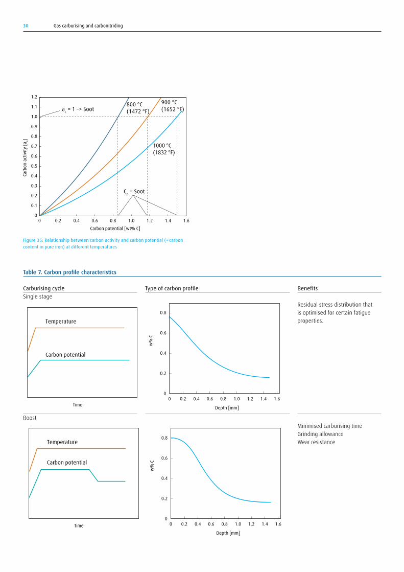
A graphical presentation of the carbon activity – carbon potential relationship is shown in Figure 35.
The carbon activity in an atmosphere should not exceed ac = 1, which is the carbon activity of solid graphite. Over that value soot will form as indicated in the figure.
in the steel microstructure and form gaseous nitrogen. The resulting equilibrium nitrogen gas pressure is so high that voids and porosities can form. These porosities will form at lower nitrogen concentrations when the temperature is increased. This is the reason why the experimentally determined nitrogen concentration decreases as temperature increases, as shown in Figure 34. The 930 °C (1706 °F) data indicates that in extreme cases the denitriding may even become higher than the nitriding rate.
5.1.3 Carbon potential controlFor the atmosphere carbon activity, the following is valid: According to the preceding paragraph, the carbon activity of the furnace atmosphere can be calculated from
ac = (K1 · PCO · PH₂)/PH₂O
The equation is valid under conditions of equilibrium, i.e. the state the system would assume if it was left undisturbed for an infinite length of time. Practical experience shows that the assumption of equilibrium in the gas phase is reasonable for normal carburising conditions. It is therefore possible to control the gas composition to the desired carbon activity if the value of the equilibrium constant K1 is known. From the expression above, we see that the carbon activity can be controlled if PCO, PH₂, and PH₂O can be controlled. This is the basis for dew point analysis (a certain value of PH₂O corresponds to a certain dew point) for the carbon activity control.
Atmosphere carbon potential is nowadays preferably controlled by oxygen probe or CO₂ infrared gas analysis. This is based on the assumption of gas equilibrium in the water gas reaction
CO + H₂O = CO₂ + H₂
This in turn leads to the assumption that equilibrium also exists for the carbon-transferring reactions:
2CO = C + CO₂ with the equilibrium constant K2 =ac · PCO₂/P²CO
CO = C + ½ O₂ with the equilibrium constant K3 =ac · PO₂½/PCO
We can therefore express the carbon activities in the furnace gas in the following alternative ways:
ac = K₂ · P²CO/PCO₂
ac = K₃ · PCO/P½O₂
From this it is evident that the carbon activity of the gas can be controlled by controlling the CO₂ content or the O₂ content, provided that PCO is known. CO₂ control with an infrared (IR) gas analyser and O₂ control with an oxygen probe are practical ways to do this. See also the tables in the Appendices.
The accuracy of the carbon potential control depends on how close or how far the atmosphere composition is from equilibrium. The deviation from equilibrium may be expressed by the ratio PCH₄(exp)/PCH₄(eq),
Gas carburising and carbonitriding30
Figure 35: Relationship between carbon activity and carbon potential (= carbon content in pure iron) at different temperatures
0
0.1
0 0.2 0.4 0.6 0.8 1.0 1.2 1.4 1.6
0.2
0.3
0.4
0.5
0.6
0.7
0.8
0.9
1.0
1.1
1.2
ac = 1 –> Soot900 °C(1652 °F)
800 °C(1472 °F)
Carbon potential [wt% C]
Carb
on a
ctiv
ity [a
c]
1000 °C(1832 °F)
Cp = Soot
Table 7. Carbon profile characteristics
0.2
0.4
0.6
0.8
00.2 0.4 0.6 0.8 1.0 1.2 1.40
Depth [mm]
w%
C
1.6Time
Temperature
Carbon potential
0.2
0.4
0.6
0.8
00.2 0.4 0.6 0.8 1.0 1.2 1.40
Depth [mm]
w%
C
1.6Time
Temperature
Carbon potential
Carburising cycleSingle stage
Boost
Benefits Residual stress distribution that is optimised for certain fatigue properties.
Minimised carburising time Grinding allowance Wear resistance
Type of carbon profile
0.2
0.4
0.6
0.8
00.2 0.4 0.6 0.8 1.0 1.2 1.40
Depth [mm]
w%
C
1.6Time
Temperature
Carbon potential
0.2
0.4
0.6
0.8
00.2 0.4 0.6 0.8 1.0 1.2 1.40
Depth [mm]
w%
C
1.6Time
Temperature
Carbon potential

Gas carburising and carbonitriding 31
To calculate the relationship between the carbon content in low-alloy case hardening steels, C, and the carbon potential, Cp , the following regression formulae originally developed by Gunnarsson [17] and later improved by others [18–19] may be used:
log CP/C = 0.055 · (%Si) – 0.013 · (%Mn) – 0.040 · (%Cr) + 0.014 · (%Ni) – 0.013 · (%Mo) – 0.013 · (%Al) – 0.104 · (%V) – 0.009 · (%Cu) – 0.013 · (%W) + 0.009 · (%Co)
5.1.4 Single step or boost carburising Different forms of the carbon concentration profile can be achieved by varying the carbon potential of the gas during the carburising cycle. The two main characteristic carbon concentration curve forms that can be attained are shown in Table 7. Single-stage carburising uses one constant carbon potential throughout the carburising cycle and results in a carbon concentration gradient with the concave curvature shown in the upper part of the table. Boost carburising uses a high carbon potential for most of the cycle time, but at the end of the cycle the carbon potential is lowered to meet hardness requirements. The resulting carbon concentration curve close to the surface is convex, as shown in the lower part of the table. As indicated in the “benefits” column, there are certain advantages to each of these two types of carburising cycles.
If high productivity is preferred, then a “boost” carburising recipe should be used. The highest possible atmosphere carbon potential should be used in the first part of the carburising cycle. This gives the fastest carbon transfer. There are two upper limits that the carbon potential must not exceed. First, the carbon potential must not exceed the limit for the creation of soot. Secondly, for parts subjected to impact or bending fatigue, the carbon potential must not result in grain boundary cementite formation in the steel. These two limits are numerically close to each other, with the soot limit being slightly higher, as shown in Figure 37.
To ensure the best results, the atmosphere carbon potential should not exceed the carbide limit.
Figure 37 shows that both the carbide and soot limit increase with increased temperature. Increased temperature can therefore shorten the carburising time not only because of the increased diffusion rate, illustrated in Figure 9, but also because a higher carbon potential can be applied, as illustrated in Figure 35.
During the second part of a boost carburising cycle, the carbon potential should be lowered to ensure a final surface carbon concentration with optimum properties and to prevent an excessive amount of retained austenite.
a. Equal carburising time b. Equal carburising depth
0.2
0.4
0.6
0.8
00.2 0.4 0.6 0.8 1.0 1.2 1.40
Depth [mm]
wt%
C
1.6
Single stage
Two stage
0.2
0.4
0.6
0.8
00.2 0.4 0.6 0.8 1.0 1.2 1.40
Depth [mm]
wt%
C
1.6
Single stage
Two stage
Figure 36: Calculated carbon concentration profiles for “single-stage” and “two-stage” carburising processes at 930°C (1706°F) with: a) identical total carburising time, 5 hours, and b) identical carburising depth of 0.7 mm. With constant time, there is an increase in depth from 0.87 to 1.10 mm, i.e. an increase of 26%. With identical carburising depths, the time decreases from 206 to 146 minutes, i.e. a decrease of 29%.
“Single-stage process” = constant carbon potential. “Two-stage process” = high carbon potential for the first three hours and low carbon potential for the last hour. (Cycles are idealised and do not include time for ramps for heating and carbon potential change.)
0.60
700
0.80
1.00
1.20
1.40
1.60
1.80
800 900 1000 1100
Carbide limit
Temperature [°C]
Carb
on p
oten
tial,
wt%
C
Soot limit
Figure 37: Cementite (lower curve) and soot limits as a function of temperature. Cementite limit is calculated for the steel 16MnCr5

Gas carburising and carbonitriding32
Table 8. The two left-hand columns show how different inlet additions of ammonia affect the value of the dilution factor Fd. In the two right-hand columns, the atmosphere true carbon potential is shown, when the desired value of the carbon potential is set at 0.8% C but when no account is taken of the dilution effect.
Ammonia addition, vol.% NH₃
Dilution factor, Fd
True carbon potential, %C, when value is set at 0.8%C without regard to dilution
012351015
10.980.960.940.930.830.77
CO₂ regulation
0.800.770.740.710.690.550.47
Oxygen probe regulation0.800.780.770.750.740.660.62
The accuracy of nitrogen activity control during carbonitriding is on a surprisingly low level when compared to carbon potential control. The reason has been the difficulty to get a reliable analysis signal with respect to residual ammonia both because analysing in itself is problematic due to deposits and corrosion in the analysing system and the difficulty in establishing the relationship between the residual ammonia concentration and the nitrogen surface concentration, (see Figure 34). A method to analyse residual ammonia avoiding the aforementioned obstacles has recently been presented [20]. It uses UV analysis for analysing residual ammonia in the exhaust gas exiting the furnace. The results presented in Figure 38 show that with this method, it is possible to correlate the nitrogen concentration analysed in foils to the residual ammonia concentration irrespective of furnace, which is not
5.1.5 Carbon and nitrogen control during carbonitridingAs described earlier, almost all ammonia dissociates upon entering the hot furnace according to the reaction
NH₃ ->1/2 N₂ + 3/2 H₂
whereby each ammonia molecule is decomposed into two molecules. This has the consequence that the atmosphere will be diluted and the dilution can be described by the dilution factor Fd:
Fd=1+(1+2×[% NH₃ x100])
The dilution has the effect that the carbon activity will be lowered on CO₂ regulation by the factor Fd² and on oxygen probe regulation by the factor Fd. Most control systems do not take account of this, making it necessary to compensate oneself for this effect, see example in Table 8.
Figure 38: a) %NH₃ in inlet – bad base for control; b) %NH₃ (residual) in atmosphere is better [20]
0.8
0.7
0.6
0.5
0.4
0.3
0.2
0.1
0
0.8
0.7
0.6
0.5
0.4
0.3
0.2
0.1
00 02 24 46 68 810 1012 1214 14
Volume fraction of ammonia addition [%] Volume fraction of ammonia addition [%]
Nitro
gen
mas
s fra
ctio
n in
foil
[%]
Nitro
gen
mas
s fra
ctio
n in
foil
[%]
Furnace material: 1.4841 900 °C Cp 0.7 50 μm Fe-foil Nitrogen: 0.2 m³/h Methanol: 0.26 l/h
Furnace material: 1.4841 900 °C Cp 0.7 50 μm Fe-foil Nitrogen: 0.2 m³/h Methanol: 0.26 l/hOld furnace
New furnace

Gas carburising and carbonitriding 33
adding ammonia as in carbonitriding, but only for a short time, of the order of 10 minutes, at the end of the carburising cycle.
Vacuum carburising completely prevents internal oxidation, as outlined in more detail in reference [2].
5.1.7 Hydrogen pickupHydrogen pickup describes the phenomenon whereby some of the hydrogen in the carburising atmosphere is transferred in atomic form to the surface layer of the carburised steel. Hydrogen solubility increases with increased temperature. Upon quenching, the amount of dissolved hydrogen after carburising remains in the surface layer, resulting in a supersaturated hydrogen concentration. In some cases, this leads to embrittlement, especially for high-strength steels and for thick case depths. Upon tempering, hydrogen will leave the surface, but to ensure efficient removal, the tempering time or the tempering temperature has to be increased.
The nitrogen/methanol atmosphere technique is a method that offers the possibility to end the carburising process with a nitrogen purge to remove hydrogen (and other active gas species) from the furnace atmosphere and thereby making the hydrogen diffuse out of the steel.
possible when just correlating the ammonia inlet concentration to the nitrogen concentration.
5.1.6 Internal oxidationThe oxygen partial pressure in a carburising atmosphere is typically of the order of 10–20 atm. This low oxygen partial pressure means that the atmosphere is reducing with respect to iron oxide (FeO), which has an equilibrium oxygen partial pressure of the order of 10–16 atm at normal carburising temperatures. However, oxides of alloying elements such as Mn, Si and Cr have equilibrium oxygen partial pressures of the order of 10–24 to 10–30 atm, which are thus much lower than the oxygen partial pressure of the carburising atmosphere. These elements can therefore be selectively oxidised during carburising. Selective oxidation is normally seen as grain boundary oxidation, but also as selective oxidation within the grains (see Figure 39). The selective oxidation depletes the matrix composition with respect to alloy content, leading to lower hardenability. Therefore, the outermost surface of carburised steels sometimes contains a pearlitic non-martensitic structure, often named HTTP (High Temperature Transformation Products) (see Figure 39b).
Additional uncontrolled oxidation may occur after furnace door openings when loading and unloading take place. This is a risk especially during heating. Internal oxides may be the starting points for crack initiation. The formation of surface pearlite results in a tensile residual stress at the surface. Therefore, internal oxidation has a detrimental effect on fatigue resistance, as illustrated in Figure 40.
The negative effects of internal oxidation on hardenability can be compensated for by ensuring that the hardenability of the steel is sufficient to result in full martensite transformation even after loss of hardenability from oxidised alloying elements. Another possibility is to compensate for the hardenability drop by adding nitrogen to the steel surface as a last step in the carburising process. This is achieved by
a b
Figure 39: Grain boundary oxidation as viewed on a) backscatter SEM image of a polished un-etched surface and b) an etched surface exhibiting pearlite in the surface zone of internal oxidation [21]
0 5 1510
90
80
70
100
110
Ni – Cr – MoCr – MoCr
Internal oxidation depth [µm]
Fatig
ue li
mit
[kg/
mm
²]
Figure 40: Effect of internal oxidation on the fatigue limit [19]

Gas carburising and carbonitriding34
is in most cases true, but nevertheless it is worth pointing out that for the most accurate carbon potential control, the CO concentration must be analysed.
If the CO concentration is not analysed, it is important to adjust the settings for the carbon potential control to the applied nitrogen/methanol mixture (see Appendix).
5.1.9.1 Gas analysis with IRInfrared (IR) gas analysis is applied in the gas analysis of multi-atom gases. While CO₂ analysis is most common, CO, NH₃ and H₂O analysis also occurs. The principle of IR analysis is based on multi-atom gases absorbing IR radiation within a wavelength range specific to each gas. Figure 41 shows an example of how the principle can be used for gas analysis. The radiation from the IR radiation source in the left part of the illustration is divided up into two radiation beams, one of which passes a cell filled with a reference gas and the other a cell filled with the gas that is to be analysed. On the right of the illustration there is a detector, the output signal of which is determined by the absorption differential of the two beams. CO₂ analysis is commonly used for the monitoring of nitrogen-methanol and endogas atmospheres. For more precise control, this method is combined with CO analysis. NH₃ analysis is applied to furnace atmospheres containing ammonia which is used in nitriding, nitrocarburising and carbonitriding processes.
5.1.8 Surface passivationSurface passivation describes the phenomenon whereby carburising can sometimes be blocked because a passive layer is formed at the surface, which prevents or decelerates carbon transfer. The passivation is often local, which leads to some surface areas not being carburised. This may lead to what is called white spots. The reason for passivation is not completely understood, but suggested causes are thin adherent oxide layers or adhered substances left over from operations such as turning or washing before carburising. The surface can be activated to eliminate the passivation effect by pre-oxidation at a temperature of about 650 °C (1202 °F) or by pre-phosphating.
5.1.9 Gas analysisPrecise carbon potential control is essential to achieve the desired product specifications. Previously, dew point analysis was common for atmosphere carbon potential control, but today carbon potential is predominantly controlled either by an oxygen probe or by infrared gas analysis of carbon dioxide. The carbon potential is determined from the expressions explained earlier
ac = K2 · P²CO /PCO₂
ac = K3 · PCO / P½O₂
where the first equation, showing that the carbon potential is proportional to the inverse of the CO₂ concentration, is used for IR CO₂ control, and the second, showing that the carbon potential is proportional to the inverse of the square root of the oxygen partial pressure, PO₂, is used for oxygen probe control. It is important to note that the carbon potential is also a function of the CO concentration for both methods. Accurate control therefore requires analysis also of the carbon monoxide concentration. However, this is rarely done, because it is mostly assumed that the CO concentration is constant and known. That
Figure 41: Simplified diagram of an IR gas analyserFigure 42: Simplified illustration of an oxygen probe installed in a furnace wall with magnification of the section where platinum electrodes are mounted
1 Radiation source, 2 Shutter, 3 Slotted disk, 4 Gas out, 5 Sample cell, 6 Reference cell, 7 Gas in, 8 Detector, 9 Calibration cell
1
2
3
4
5
7
8
6
9
5
6
1
34
1 Furnace wall, 2 Furnace atmosphere, 3 Thermal element, 4 Reference air, 5 ZrO₂, 6 Inlet
2
Gas carburising and carbonitriding 35
A sample gas scanning system makes it possible to conduct step-by-step gas analysis from different positions in the furnace. The actual gas analysis is compared with set points for different parts of the furnace and the deviation between actual reading and set point is the input signal for automatic adjustment. The adjustment signal is sent from the control cabinet to the flowtrain, which automatically adjusts flows and mixtures in order to attain the set point gas analysis inside the furnace.
Up to five different sampling positions are analysed in sequence. Gas flows and mixtures are adjusted in the flowtrain to maintain the set points in the different furnace zones (based on the recipe) and to minimise gas flows in order to reduce cost.
The CARBOFLEX® control cabinet contains a PLC for control and a PC with a touchscreen as the human/machine interface, seen on the left in Figure 28. Settings of the atmosphere parameters, recipe handling, alarm setting, start up and stop, calibration of analysers, and viewing of actual furnace atmosphere data are carried out from the PC touchscreen on the control unit.
The system enables historical logged data to be stored, viewed and evaluated for statistical process control and can be connected to a central computer supervision system and made remotely accessible via modem or Internet.
Figure 43 shows the layout for a control system that handles gas sampling, gas analysis (in this case both for CO and oxygen probe), and flow control for a nitrogen/methanol system installed at a pusher furnace. (This system has the option of injecting water at the end of the furnace in order to lower the carbon potential and was developed to achieve the results described in reference [22].)
5.1.9.2 Oxygen probeUsing an oxygen probe, the oxygen partial pressure is measured directly in the furnace chamber in accordance with the principle that is shown in Figure 42. The probe or sensor consists of an inner ceramic tube surrounded by a protective tube. The air flows on the inside of the ceramic tube, while on the outside, in the gap between the protective tubing, there is a flow of furnace gas. The difference in the oxygen concentration between the inside and outside of the inner tube is then measured as an electric voltage with the aid of a zirconium oxide cell with platinum electrodes mounted on both sides. The voltage is a direct measure of the atmosphere oxygen partial pressure. The oxygen probe is commonly used for the control of nitrogen-methanol or endothermic gas (endogas) atmospheres.
5.2 Automatic atmosphere composition control
The CARBOFLEX® ACS atmosphere control system which was described earlier, see Figure 28, allows full control over the carbon potential in up to four zones per furnace. The process parameters time, temperature and carbon potential are defined in a process recipe. The recipes vary according to steel grade and quality, dimensional requirements, etc. Set points are defined in the CARBOFLEX® atmosphere control cabinet to meet the requirements for carbon content and process safety.
A gas sample from a specific zone in the furnace is pumped to the control cabinet, where the sample is analysed. Coupled to gas analysis not only of CO₂ or from an oxygen probe but also analysis of CO, the control system yields improved accuracy in the carbon potential control (see section 5.1.3). Methane (CH₄) analysis additionally controls the risk of creating soot deposits.

Gas carburising and carbonitriding36
In summary, the CARBOFLEX® atmosphere control systems offer the following benefits:
• Optimisation of the heat treatment cycle• Increased productivity of up to 15% in many cases• Enhanced process control• Alarm for deviations from set points• Easy operation with PC-based HM interface• Precise control of the surface carbon content• Fulfilment of high surface quality requirements in terms of brightness
and freedom from carbon deposits• Quality assurance through advanced process control with recipes for
different parts, dimensions and types as well as through easy collection of historical data
• High levels of safety thanks to minimal use of flammable gases at the furnace inlet and exit and nitrogen-based safety purge function
• Reduced costs due to minimised total gas consumption, reduced reject reworking and lower dependence on operator skills
Figure 43: Example of a closed loop atmosphere control system including atmosphere supply with membrane nitrogen, flow control, gas sampling, gas analysis and control cabinet
Gas analysis
Controlcabinet
N2
Methanol
Calib
ratio
n ga
s
Methanolpump
Control panel
Furnace
Gasinlet

Gas carburising and carbonitriding 37
CARBOFLEX® cabinet
Zone 1 Zone 2 Zone 3 Zone 4
Gas/methanol inlets
CO2 + CO Oxygen probe
Gas sampling system
Oil
Nitrogen/methanol/C3H8/air Nitrogen/water

Gas carburising and carbonitriding38
6.1 Safety awareness
Safety is a key concern when working with industrial processes. Therefore, any person working in the heat treatment industry should be aware of the hazards from processes and equipment and apply appropriate safeguards to control the risk at an acceptable level.
In this section, The Linde Group wants to create awareness of potential safety hazards related to gas usage, its sources and control options in heat treatment-related processes. Avoiding harm to people, society and the environment are important priorities for The Linde Group. This means that we expect all of our people to behave and conduct themselves at all times in a manner that safeguards the health, safety and security of people and protects the environment.
Products and services provided by The Linde Group to customers around the world are measured against high safety standards. But not only the “end” product or service, but rather the whole value chain is taken into account when it comes to safety issues – starting from gas production and gas supply to gas usage as well as the installation and commissioning of gas application technology.
Before we have a look at the whole value chain, we will focus on the gases used, the potential safety hazards and the related control options.
6.2 Gases used in the process
The gases and methanol used in the carburising and carbonitriding process cover both atmospheric pressure carburising and carbonitriding, as well as the low pressure processes. In this expert edition, the description is limited to the atmospheric pressure processes and therefore the gases C₂H₂ (acetylene), H₂ (hydrogen), and He (helium),
which are used in the low pressure processes, are not covered here. For further information on these processes, the reader is referred to reference [2].
Gas and methanol usage in atmospheric pressure processes is divided into:
1) usage as carrier gas that includes N₂ (nitrogen) and CH₃OH (methanol) and 2) usage as enriching gas that includes hydrocarbons
6.3 Potential safety hazards and their sources
The main hazards related to the used gases and to methanol are:
• Explosions/flammability/fire• Toxicity and asphyxiation• Cold Burn hazards• Pressurised piping and the gas expansion hazard
Some additional hazards related to the use of cold liquid gas are:
• Gas expansion risks • Embrittlement of the material in contact with the cold liquid
Some additional hazards related to the use of compressed gas are:
• Pressure increase from heating (fire)• Leakages
Detailed information on these hazards is found in safety standards and regional and national safety regulations. Only hazards related to heat
6. Safety.

Gas carburising and carbonitriding 39
treatment, carburising specifically, will be further elaborated in this document.
Examples of hazards related to the use of heat treatment equipment are:
• Failure of energy supply• Failure of atmosphere gas supply• Flame failure control (burner(s) and pilot(s)) and consequently the
spillage/ leakage of asphyxiating gases into the room• Failure/disorder of control systems• Pressure of flow control devices; Low or high temperature detectors• Mechanical hazards such as moving parts, cranes, loading and
unloading equipment, robots, trucks and forklifts, charging doors, rotating shafts, moving rolls or conveyors, hydraulic leaks, etc.
Hazards related to equipment will not be further elaborated in this document. The focus in the following description is on hazards connected with the use of gas.
6.3.1 Explosions/flammability/fireFor ignition or explosion to occur, the following must be present: fuel, oxygen, ignition source (an exclusion here is acetylene which can violently decompose in the absence of oxygen). Flammability risk can be described in relation to the Safety Triangle shown in Figure 44. A triangle of this kind can be devised at a specific temperature and for a specific combustible gas in combination with oxygen. In the shaded area in the middle of this triangle, the gas mixture is flammable. This flammability region broadens as temperature decreases.
The flammable gases commonly found in these atmospheres are hydrogen, carbon monoxide, hydrocarbons, vaporised or dissociated methanol (dissociation produces hydrogen and carbon monoxide), and dissociated ammonia (forms hydrogen and nitrogen).
The European safety standard EN 746-3 [24] gives a more definite description of the flammability range:
“As a general rule, any gas mixture containing more than 5 volume percent combustibles H₂+CO+CH₄ of which methane (CH₄) is not more than 1 volume percent where the remainder of the mixture is non-flammable, is considered to be flammable. Any gas mixture that contains more than 1 volume percent hydrocarbons (CnHm) or 2.5 volume percent ammonia (NH₃) where the remainder of the mixture is non-flammable is also considered flammable. A flammable gas which contains 1 volume percent or less oxygen cannot itself form an explosive or flammable mixture.”
The use of nitrogen to ensure safety during start-up and shutdown of furnaces may be illustrated in relation to Figure 44. When starting from an air-filled furnace, corresponding to the top left corner of the diagram, nitrogen is purged into the furnace until the oxygen concentration is lowered to point C. Fuel in the form of combustible gas is then added, which means that the composition is changed along the line C–S–100% fuel. This avoids entering the flammability region L–S–U. When shutting down, the furnace is first purged with nitrogen down to composition B before opening to air. Nitrogen is also used as a purging gas in alarm situations such as failure of electric power or if the furnace temperature falls below the safety temperature.
An explosion will occur if a flammable mixture of atmosphere gas and air has accumulated in a confined area and is suddenly ignited. This danger exists if flammable gases are being used at a process temperature below auto-ignition (750 °C (1382 °F)). The destructive power of the pressure wave from an ignited flammable mixture depends on the amount of gas and the heat of combustion of the fuel gas, the combustion mode, and the configuration of the confinement space. The energy released is absorbed by the surroundings and in the worst case destroys them.
Figure 44: The flammability triangle
Fuel concentration [vol%]
Oxyg
en co
ncen
tratio
n in
gas
mix
ture
[vol
%]
L Lower flammability limit in airU Upper flammability limit in airS Min O2 con. for flammabilityC Start upB Shut down
L
4
8
12
16
B20 40 60 80 100
U
SC
20
00

Gas carburising and carbonitriding40
There is only the operation alternatively called cryo-treatment or sub-zero treatment at which liquid gases, in this case liquid nitrogen, are applied directly in an operation in the heat treatment workshop.
6.3.4 Pressurised piping and the gas expansion hazardThe nitrogen supplied to the furnaces is under pressure. The gas supply should be locked out from the furnace and the pressure in the lines released in a controlled manner prior to performing maintenance on the system. Failure to do so can lead to unexpected releases of energy or introduction of nitrogen into the furnace. Furthermore, any pipe section designed so that liquid can be trapped inside must be equipped with a safety valve.
6.4 Control of safety hazards
6.4.1 General safety regulations and guidelinesParts of the international safety standard ISO 13577 [23], e.g. part 3 about “Generation and use of protective and reactive atmosphere gases”, are still under development. It has not yet been possible to come to a completely unified agreement between countries on the exact text of the ISO standard, but there are some specific pages describing special requirements for Japan, the USA and the EU. The intention is that the new ISO standard, when published, will replace regional or national standards. However, the existing European and American standards [24–25] as well as other national standards will for some time still serve as guidelines.
6.4.2 Explosions/flammability/fireMeasures to prevent oxygen forming flammable and inherently explosive mixtures with the furnace atmosphere are for instance:
• Maintain a positive furnace pressure by proper gas flow to eliminate the ingress of air into the furnace.
• Vacate the furnace atmosphere from the furnace by controlled combustion of the exit gas.
• Use good natural ventilation, especially when controlled combustion of the exit gas cannot be ensured.
• Use flame curtains and pilot burners at the exhaust when a temperature below 750 °C (1382°F) does not automatically ignite a flammable mixture.
Possible ignition sources are:
• Surfaces with high temperature such as furnace inner walls, electric heating elements, and burners or burner tubes
• Sparks caused by friction or impact, for instance from fans or electric insulators as well as non-spark-free tools
• Catalysers such as soot, sulfur-containing gases, finely dispersed metal particles, chemical reactions between oxygen and fuel gases, electrostatic charging, and local overheating by soot fire
• Pilot burners and other open burners, lit cigarettes or flame curtains• Adiabatic heat from compression processes
6.3.2 Toxicity and asphyxiationCarbon monoxide is highly poisonous and a concentration as low as 400 ppm is harmful. Carbon monoxide enters the blood and takes the place of oxygen in haemoglobin. Carbon monoxide uptake by the body is very fast, about 250 times faster than oxygen uptake, and even very small CO concentrations can be dangerous. Carbon monoxide has no odour, which makes the hazard more serious. Carbon monoxide has the same density as air and will therefore not disperse naturally. Heat treatment shops should therefore ensure that there is good ventilation in the work areas.
When the oxygen concentration in inhaled air is reduced from 21% to 10%, there is a serious hazard of asphyxiation. Oxygen deficiency can be caused by any asphyxiating gas, the most common being nitrogen. An example of this is when repair or inspection is required in a furnace that has been filled with nitrogen. Whenever entering confined spaces, a risk assessment needs to be carried out beforehand and a rescue plan needs to be in place.
6.3.3 Cold burn hazardsDirect contact with cryogenic liquefied gases such as liquid nitrogen or cold nitrogen vapour will produce effects on the skin similar to burns. Cold burn will also occur when exposed or insufficiently protected parts of the body come into contact with un-insulated pipes or vessels. The skin will stick fast by virtue of the freezing of available moisture, and the flesh will be torn on removal. The wearing of wet clothes should be avoided.
Cold burns can be avoided by use of suitable protective clothing, including leather gloves, boots (trousers should be worn outside the boots), overalls and face shields or goggles as appropriate to the work being carried out.

Gas carburising and carbonitriding 41
When using flammable gas mixtures, it is required that the furnace temperature is above the ignition temperature. A safety temperature with good safety margins is therefore used in industrial furnaces. In the European standard [24], the safety temperature is defined at 750 °C (1382 °F). The process temperature for carburising and carbonitriding lies above this safety temperature. In the case of a temperature drop due to failure in energy supply or electric or burner heating, there must be a control system that automatically closes the valves for flammable gas and opens a valve for nitrogen supply.
When operating heat treatment furnaces below the safety temperature, which is relevant at the inlet and outlet of continuous carburising furnaces, precautions must be taken to ensure that explosive mixtures are not created. A first precaution is to ensure that fuel concentrations are outside the flammability area. This can be realised either by establishing a non-flammable composition all along the furnace or by injecting nitrogen at inlets and outlets to lower the concentration of flammable gases. A further precaution is to avoid or minimise the amount of oxygen in contact with the flammable constituents.
Any commercially fabricated industrial furnace must meet the industrial codes of the company where it will be installed. A number of emergency safety functions should be integrated into the furnace and they should in an emergency situation be able to automatically and safely shut down the furnace. Typical situations would include furnace over-temperature or loss of heating, loss of atmosphere, electric system failure, and flame safety. The manufacturing plant should also train its employees on proper procedures for the unexpected or emergency situations that may arise. Hazard reviews and appropriate documentation are mandatory before starting the operation. Modifications to existing systems must be reviewed with respect to their impact on safety.
6.5 Safe use of gases along the value chain
Linde offers various gas supply solutions, which can be tailored to the customer’s requirements. As safety is a key concern for Linde, the highest safety standards apply to all gas supply services, the installation of delivery systems and the commissioning of application technology equipment.
Starting with the gas supply to the customer, Linde takes care that every gas supply mode fulfils high safety standards. If the customer requests liquefied gas tank supply for instance, Linde takes the location, its foundations and floor surfaces, the gas tank itself and the gas supply route into safety considerations.
Regarding gas usage, in the case of oxygen for instance, the customer is instructed in safe gas handling. A risk assessment helps to support the customer in handling industrial gases safely.
Regarding the installation and commissioning of gas application technologies, the customer can expect that a robust equipment safety concept is in place. Furthermore, Linde’s experts can start with a full review of the process landscape and a diagnosis of existing problems including safety risks regarding changes in the operating systems. A plan detailing how to overcome safety issues is created and implemented together with the customer.
The installation and commissioning process includes, where applicable, careful process diagnostics and tailoring of gas consumption to ensure the correct furnace gas atmosphere and distribution. The maintenance of safety-relevant components and a joint risk analysis and hazard review support this common goal. In addition, Linde experts can provide training on all aspects of the installed solution so that plant personnel can operate the system independently. Of course, Linde engineers can be called on afterwards if the customer requires further assistance.

Gas carburising and carbonitriding42
Authors: Michael-Peter Graf, Torsten Holm, Akin Malas, Sören Wiberg
1. Krauss, G., 1989. Steels: heat treatment and processing principles. ASM Int., Materials Park.
2. Linde AG. Furnace Atmospheres No. 6 - Low Pressure Carburising and High Pressure Gas Quenching. Linde Expert Edition.
3. Holm, T., 1973. Material properties of carburised and carbonitrided steels. IVF 73625, Stockholm.
4. European Standard EN ISO 2639, Determination and verification of the depth of carburised and hardened cases
5. Holm, T., Olsson, P., Troell, E., 2010. Steel and its Heat Treatment. Swerea IVF, Gothenburg.
6. Thelning, K.E., 1975. Steel and its Heat Treatment. Butterworths, London.
7. Namiki, K., Isokawa, K., 1968. Trans. IS13, Vol. 26. 8. Herring, D.H., 2012. Vacuum Heat Treatment – Principles, Practices,
Applications. BNP Media, Troy, Michigan. 9. Linde Gas, CARBOJET™. High-speed gas injection for advanced heat
treatment, brochure. 10. CARBOJET®. High-speed gas injection in a pit furnace, brochure.11. Laumen, C., Åström, A., Jonsson, S., 1999. Härterei Techn. Mitt., Vol.
54, No 1. 12. Grabke, H.J., 1990. Härterei-Technische Mitteilungen, Vol. 45. 13. Collin, R., Gunnarsson, S., Thulin, D., 1972. Iron Steel Inst., Vol. 20. 14. Ågren, J., 1986. Scripta Metall, Vol. 20. 15. Holm, T. Unpublished work.16. Ågren, J. Private communication.17. Gunnarsson, S., 1967. Härterei-Technische Mitteilungen, Vol. 33. 18. Neumann, F., Person, B., 1968. Härterei-Technische Mitteilungen,
Vol. 33.19. Uhrenius, B., 1977. Scand. Journ. Met., Vol. 6. 20. Hoffman, F. et al, 2011. 26th ASM Heat Treating Society Conference. 21. Randelius, M., Haglund, S., Thuvander, A., 2003. Gas carburising and
vacuum carburising and the case hardening steels Ovako 255 and 16MnCr5 – evaluation of distortion and fatigue properties. Report No IM-2003-546, Swedish Institute for Metals Research, Stockholm.
22. Holm, T., Arvidsson, L., Thors, T., 1998. IFHT Heat Treatment Congress, Florence.
23. ISO 13577-3 Industrial furnaces and associated processing equipment – Safety – Part 3: Generation and use of protective and reactive atmosphere (in development, not published).
24. EN-746-3, 1997: Industrial thermoprocessing equipment - Part 3: Safety requirements for the generation and use of atmosphere gases.
25. NFPA 86C, Standard for Industrial Furnaces Using a Special Processing Atmosphere. This standard is incorporated in and replaced by the 2003 edition of NFPA 86.
References

Gas carburising and carbonitriding 43

Linde AGGases Division, Carl-von-Linde-Strasse 25, 85716 Unterschleissheim, Germany Phone +49 89 31001-0, [email protected], www.linde-gas.com