Embed Size (px)
Citation preview

→ Expert edition
Furnace atmospheres no. 6.
Sintering of steels.
02 Sintering of steels
1. Gas carburising and carbonitriding 2. Neutral hardening and annealing3. Gas nitriding and nitrocarburising4. Brazing of metals5. Low pressure carburising and high pressure gas quenching6. Sintering of steels
Preface.
This expert edition is part of a series on process application technology and know-how available from Linde Gas. It describes findings in development and research as well as extensive process knowledge gained through numerous customer installations around the world. The focus is on the use and control of furnace atmospheres; however a brief introduction is also provided for each process.

03Sintering of steels
Passion for innovation.
With R&D centres in Europe, North America and China, Linde Gas is leading the way in the development of state-of-the-art application technologies. In these R&D centres, Linde's much valued experts are working closely together with great access to a broad spectrum of technology platforms in order to provide the next generation of atmosphere supply and control functionality for furnaces in heat treatment processes. As Linde is a trusted partner to many companies in the heat treatment industry, our research and development goals and activities are inspired by market and customer insights and industry trends and challenges. The expert editions on various heat treatment processes reflect the latest developments.
More Information? Contact Us!Linde AG, Gases Division, Carl-von-Linde-Strasse 25, 85716 Unterschleissheim, Germany
[email protected], www.heattreatment.linde.com, www.linde.com, www.linde-gas.com
Linde Gas Research Centre Unterschleissheim, Germany

Sintering of steels04
Contents.
Preface 2
Passion for innovation 3
1. Introduction 6
2. Process 7
2.1 Powder metallurgy processing 72.2 Sintering 82.3 Applications and properties of sintered steel components 112.4 Metal injection moulding 122.5 Heat treatment of sintered parts 132.5.1 Carburising and carbonitriding 132.5.2 Nitriding and nitrocarburising 142.5.3 Steam treatment 142.6 HIP – hot isostatic pressing 15
3. Furnaces and equipment 16
3.1 Furnaces 163.2 Atmosphere equipment 183.2.1 High-speed gas injection for improved gas homogeneity 183.2.2 Methanol equipment 18
4. Atmosphere generation, gas supply. 20
4.1 Nitrogen, argon and hydrogen supply 204.2 Endothermic gas, methanol, ammonia and enriching gases 214.3 Examples of supply solutions 224.4 Atmosphere flow rate and flow configuration 22

Sintering of steels 05
5. Atmosphere control 26
5.1 Theory and principles 265.1.1 The delubrication – preheating step 265.1.2 The sintering – hot zone step 305.1.3 Oxidation control 315.1.4 Carbon control 375.1.4.1 Carbon control in N₂/H₂/CH₄ atmospheres 405.1.4.2 Carbon control in N₂/CO/H₂ atmospheres 425.1.4.3 Carbon control in N₂/CO atmospheres 435.1.5 Nitrogen control 435.1.6 Cooling after sintering 445.1.7 Carbon control theory in the MIM sintering process 445.2 Sintering atmospheres for stainless steel and high speed steel 465.3 Sintering atmospheres for non-ferrous metals 475.4 Sintering atmospheres for permanent magnets 485.5 Vacuum sintering 485.6 Atmosphere analysis 505.7 Advanced atmosphere control 52
6. Safety 54
6.1 Safety awareness 546.2 Gases used in the process 546.3 Potential safety hazards and their sources 546.3.1 Explosions/flammability/fire 556.3.2 Toxicity and asphyxiation 566.3.3 Cold burn hazards 566.3.4 Pressurised piping and the gas expansion hazard 566.4 Control of safety hazards 566.4.1 General safety regulations and guidelines 566.4.2 Explosions/flammability/fire 566.5 Safe use of gases along the value chain 57
References 58

Sintering of steels06
In order to achieve specific properties and the desired surface quality after sintering of a steel object, numerous process parameters need to be controlled. The most critical parameters are the composition, function and control of the furnace atmosphere. In sintering processes, the function of the atmosphere is to ensure good bonding between powder particles during sintering with no defects such as oxides or decarburised or overcarburised areas. Therefore, it is important to ensure a reliable supply of required gases and process gas blends but also to integrate leading application technologies to enable precision control of furnace atmospheres and thus achieve the desired product specifications of steels.
The purpose of this expert edition is to deliver a technically comprehensive overview of sintering processes with critical influencing parameters in terms of the required equipment and furnace atmosphere. This expert edition should deliver valuable background information on a complex topic in a structured, single document in order to achieve a higher confidence level in the readers’ business decisions.
Each of the expert editions has a similar content structure. The first part focuses on the process, describing the basic principles in sintering and related powder metallurgy techniques. The next section focuses on the different types of furnaces and the required equipment in the process. The furnace atmosphere generation and required gas supply are explained in the fourth section; the interaction between furnace atmosphere and the steel powder part surface and how to control the atmosphere is described in the fifth section. As flammable, asphyxiating and toxic gases are used in sintering processes, safety issues need to be addressed in the last section; this is an important concern of Linde Gas.
1. Introduction.

Sintering of steels 07
2.1 Powder metallurgy processing
Powder metallurgy (PM) techniques offer the possibility of near net-shape production of components with complicated geometries without subsequent machining. Almost 100% usage of the material is achieved, resulting in little or no scrap. As a consequence, the energy required per kg of finished parts is less than for other manufacturing processes. Another advantage of PM techniques is that it is possible to use alloy compositions that are not possible with conventional melting and casting. This is especially true of the hot isostatic pressing (HIP) processing route.
Using various production techniques, metal powders are compacted into parts or semi-finished products. Uniaxial pressing followed by sintering makes up more than 80% of PM part production. Other methods include metal injection moulding (MIM), additive layer manufacturing (rapid prototyping), HIP and powder forging. As illustrated in Figure 1, gases and controlled atmospheres are, in addition to their use in sintering, also used in several other steps in PM production, including reduction of iron oxides with hydrogen for iron powder production, inert gas atomisation when producing powder from liquid metal, annealing of water-atomised powders in hydrogen to reduce oxides, argon or nitrogen as pressure medium in hot isostatic pressing (HIP), and heat treatment and surface hardening of sintered parts.
The dominant application of controlled atmospheres in PM processes is for the sintering of ferrous parts and that is the focus of this booklet. It is estimated that 80 to 85% of all the gases used in PM processing are for the sintering process. In the following process descriptions, the focus is on sintering of steels, but metal injection moulding is also briefly described.
The base material for PM production is iron or steel powder produced along three alternative routes:
1. Reduction of iron oxides (ore concentrates) with coke
2. Inert gas atomising of molten steel
3. Water atomising of molten steel
Powders used in the traditional press-and-sinter process typically contain 0.5 to 1% of an admixed lubricant with the function of reducing friction during pressing, thereby facilitating compaction and ejection of the compact from the die. Widely used lubricants include EBS (ethylene bis stearamide), stearic acid, synthetic waxes, zinc stearate, lithium stearate, and mixtures of these. The addition of a lubricant to a powder affects many of its engineering properties, including powder flow, apparent density, green strength and compressibility. Lubricants volatilise and decompose during heating to the sintering temperature.
Carbon and other alloying elements have to be added to iron powders to obtain the desired properties such as strength and ductility. Carbon is normally added to the iron powder in the form of graphite. Metallic alloying elements are included in two ways:
1. Water atomisation of the liquid alloy resulting in a homogenously alloyed powder
2. Mechanically blending plain iron powder with the required alloying element powder. The actual alloying takes place during the sintering process.
2. Process.
Melt
HIP
Ar, N₂Ar, N₂, H₂, CO, CH₄, C₃H₈
H₂
H₂
Iron ore
Inert gas atomising
Water atomising Annealing Sintering Heat treatment
Annealing of sponge iron
Figure 1: An illustration of gas applications in different PM process steps. Ar=argon; N₂=nitrogen; H₂=hydrogen; CO=carbon monoxide; CH₄=methane; C₃H₈=propane.

Sintering of steels08
Sintering is a thermal treatment for bonding particles into a coherent, predominantly solid, structure via mass transport events that often occur on the atomic scale. The bonding leads to improved strength and lower system energy [2].
Before sintering, a preform is produced by cold pressing. For that, the metal powder is mixed with a lubricant and poured into a die with the form and dimensions close to that of the final sintered part. Shrinkage during sintering has to be taken into account when deciding the dimensions of the die. The cold pressed part, called a green body, has a limited strength, see Table 1, and care must be taken during handling and transportation before sintering in order not to break it.
For steels, the cold pressed green body is typically sintered for 20–30 minutes at high temperature. The higher the sintering temperature, the shorter is the sintering time required. In most cases, the limitations of the furnace equipment restrict the sintering temperature to 1120–1150°C (2050–2100°F) for the sintering of steels. Higher temperatures are used for stainless steels, for MIM green bodies and for liquid phase sintering.
When heated to a high enough temperature, the powder particles will bond to each other by mass transport primarily through volume and surface diffusion, but also by grain boundary diffusion, viscous or plastic flow and vapour transport. Diffusion mass transport is initiated at contact points between adjacent particles and, in the early stage of sintering, this leads to neck formations and growth as illustrated in Figure 2. In the later stage of sintering, pores, initially with a pyramidal shape, adopt a rounded form. Large pores increase in size by absorbing smaller ones and small pores disappear in the neighbourhood of grain boundaries.
Carbon steels and copper- and nickel-alloyed steels are usually in the mechanically blended powders group. Homogenously alloyed powders are often sinter-hardened or separately heat treated.
Properties of some common powders are presented in Table 1. The definitions of the different properties in the table are as follows:
• Apparent density is determined by pouring the powder through a standard funnel into a small cup, levelling off the surplus powder on top of the cup and dividing the weight of powder contained in the cup by the cup volume (g/cm³).
• Flow is defined as the time in seconds that 50 g of dry powder needs to pass through the aperture of a standard funnel.
• Green density is the density of a cold pressed (not sintered) body in g/cm³.
• Green strength is the bending strength of a cold pressed compacted (not sintered) rectangular test bar in MPa.
2.2 Sintering
Sintering is a near net-shape forming technique that is increasingly used because of benefits such as efficient use of material and reduced need for machining. There is a steady drive for achieving improvement in strength and toughness and for reducing the scatter of these properties in sintered PM objects. Furnace atmosphere quality and control play a crucial role in this development. Linde Gas offers a number of ways to achieve these improvements.
Table 1. Properties of some Höganäs powders. Green density and green strength were determined after compaction with a pressure of 600 MPa in a lubricated die (as an exception, the data for MH80.23 was determined after compaction with a pressure of 410 MPa) [1]
Iron powders
Distaloy powders
Astaloy powders
Powder grade
NC100.24SC100.26M80.23ASC100.29ASC100.30PASC60SASEDCDHHPABAEAMo85MoCrM
Apparent particle size [μm]20–18020–18040–20020–18030–200
20–15020–15020–18020–18020–180
2020
Apparent density [g/cm³]2.442.662.302.963.023.152.832.822.283.413.373.053.053.303.283.12.95
Flow [s/50g]
3028332424252728242222242423232525
Carbon [%]
<0.01 <0.01 0.08 0.002 0.001 0.03 <0.01 <0.01 <0.01 0.01 0.01 <0.01 <0.01 0.01 0.01 <0.01 <0.01
Green density [g/cm³]
7.027.126.297.217.277.107.097.117.167.137.077.187.187.017.147.186.97
Green strength [MPa]
4740243839324139222925363517222324

Sintering of steels 09
The driving force for sintering is the minimisation of the free surface energy, i.e. a reduction of the pore surface area. Fine particle powders with large specific surface and high internal porosity will sinter faster than coarse powders (Figure 3). However, the use of very fine powders has the disadvantages that cold pressing is more difficult and that shrinkage during sintering increases. Shrinkage is a decrease in dimensions. The opposite, an increase in dimensions, or swelling, may occur under given sets of conditions.
D D Grain boundary
Initial point contact Early stage neck growth(short time)
Late stage neck growth(long time)
Terminal condition, fully coalesced spheres (infinite time)
Neck
1.26D
Figure 2: The growth of a neck between two spherical particles during sintering [2]
Figure 3: A schematic representation of the temperature-dependent densification of a fine (1–10 μm) and a coarse (50–100 μm) powder mass. Sintering time and green density are constant. T=temperature, Tm=melting temperature [3]
Figure 4: Tensile strength (σuts), elongation (δ₅) and density of sintered iron as functions of sintering time at two temperatures [1]
0.2
Relative density
finecoarse
Relative sintering temperature T/Tm, K/K
Theoretical density
Greendensity
0.3 0.4 0.5 0.6 0.7 0.8 0.9 1.0
00 0
2
4
6
8
1050
100
150
6.2
6.3
15 30 60 90 120 150
850 °C (1560 °F)
850 °C (1560 °F)
850 °C (1560 °F)
1150 °C (2100 °F)
1150 °C (2100 °F)
1150 °C (2100 °F)
Sintering time, min
δ5
Dens
ity, g
/cm
3
Elon
gatio
n, %
Tens
ile st
reng
th, M
Pa
σuts
Sintering of steels10
High temperature sintering, at temperatures up to 1350 °C (2460 °F), has the advantage of producing a more homogenous part with better mechanical properties (Table 2) and reduced oxygen concentration in the PM compact after sintering. High sintering temperatures also have the advantage that alloying elements with a high tendency to form oxides, such as manganese, chromium and vanadium, can be used without the formation of oxides. Despite these advantages, high temperature sintering of standard sintered steel parts has not gained any substantial market share mainly because of the higher demands put on furnaces during high temperature sintering. However, high temperature sintering is used for high-speed steel, stainless steel, neo-magnets and new ferrous alloys.
Sintering is a complex process in terms of control. Parameters include furnace temperature profile, conveyor belt speed, belt loading capacity, furnace door opening height, furnace cooling rate, furnace entry and exit curtain integrity, furnace atmosphere volume and composition, atmosphere inlet location and flow direction, PM part composition, and external influences such as draughts from door openings in the process shop. A good sintering process can be simply described as the one that produces good bonding between the metal particles with minimum oxide content, has tight carbon control, forms round pores between particles, has good dimensional control and produces consistent quality.
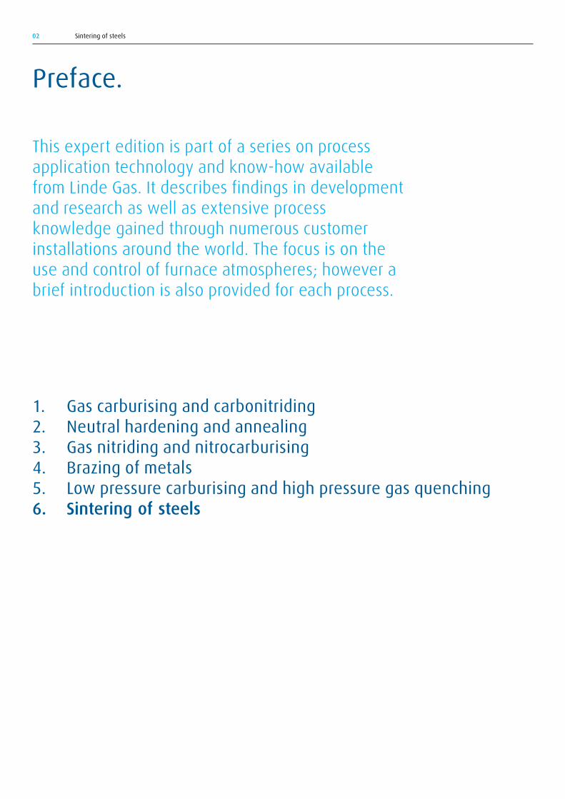
During sintering of mechanically blended powders, alloying will take place at locations where necks are formed between iron and alloy particles. Neck formation will depend on the diffusion rates of the alloy element and of iron in the various phases that will be formed at the neck. The alloying element will diffuse from the surface into the centre of the iron particles. This results in a homogenisation of alloy composition to a degree that will increase with temperature and time. Normal sintering times and temperatures are enough to yield an even carbon concentration, but not enough for a complete homogenisation of metallic alloy element concentration in the sintered part (Figure 5). The microstructure of sintered steel manufactured using mechanically blended powders is therefore generally heterogeneous.
During sintering of copper-alloyed powders, the copper will melt at normal sintering temperatures. The melt will form a continuous film adhering to the iron particles. With high solubility in the solid iron particle phase, the liquid copper film will eventually disappear, leaving behind large pores. As a result, the part swells.
A special kind of sintering with a transient liquid phase is referred to as activated sintering. Here a base powder is admixed with a small amount of metal or metal compound having a melting point above sintering temperature, but which forms a low-melting eutectic together with the base metal. This will enhance the formation of necks between adjacent particles of the base metal. Ferro-phosphorus added to iron powder serves as such an activator because a low-melting-point eutectic is formed at 1050 °C (1920 °F) between iron and iron phosphide. In addition to enhancing neck formation, the added phosphorus has a second advantage; it stabilises ferrite and destabilises austenite. The self-diffusion coefficient for iron in ferrite is approximately 300 times greater than in austenite. Consequently, a phosphorus addition will enhance the sintering process.
Figure 5: Homogenisation of nickel and carbon during sintering at 1120°C (2050°F) [1]
Sintering of steels 11
2.3 Applications and properties of sintered steel components
About 70% of all sintered steel parts are used in cars and other vehicles. A US car contains on average about 20 kg of sintered steel parts whereas a European car has about 9 kg and an Asian car 5 kg [5] (data from 2006). The difference is due to the fact that US cars tend to be heavier and that they utilise automatic gear boxes. Such parts are more suitable for PM production than those used in a lighter, manual European car. Some examples of the use of sintered parts are:
• Lock parts require high strength, toughness, wear resistance and dimensional stability. A sintered part manufactured from diffusion alloyed powders can match these parameters, achieving a density between 6.8 and 7.0 g/cm³.
• Belt pulleys or chain sprockets can be found in every automobile. They are components ideally suited to the PM process as they permit an intricate weight-saving geometry. Sponge iron usually forms the base powder, ensuring ample green strength. Sintered density ranges from 6.5 to 6.8 g/cm³.
• Synchronising hubs for automobile gear boxes are mostly produced by the PM process route. High strength, fatigue resistance, wear resistance and dimensional stability are demanded for this application. Diffusion alloyed powders are the common choice of material to meet the demands. Densities are in the range 7.0–7.2 g/cm³.
• Sintered bearings are a well-established application. The porosity of sintered parts allows absorption of oil for lubrication. Normally, sintered density is less than 6.2 g/cm³ and powders containing Fe-Cu or Fe-C are often used.
• Power tool parts often utilise diffusion alloyed powders, achieving a sintered density of about 7.0 g/cm³. Subsequent heat treatment further increases wear resistance and strength. In some cases, warm compaction is used to further increase density and improve gear strength.
Examples of automotive sinter steel parts are given in Figure 6. Tensile and fatigue strength of sintered steels are approximately proportional to density (Figure 4), whereas impact strength increases exponentially with increasing density. High strength sinter steels with high relative densities, above 95%, often have the same strength as wrought steel. For a given cooling rate, strength also increases with the hardenability of the sintered alloy as more martensite is formed. Double pressing, double sintering and high temperature sintering are all methods of increasing density and strength. For economic reasons, sintering at temperatures below 1150 °C (2100 °F) and single pressing and sintering are preferred. Other ways to improve strength are heat treatment techniques such as carburising and nitriding (see Section 2.5). Diffusion alloyed powders give higher strength than pre-alloyed powders. However, in some applications, where a homogenous structure and alloy concentration are required, then pre-alloyed powders have to be used instead of diffusion alloyed powders. Höganäs Astaloy Mo is an example of a pre-alloyed powder that has been shown to yield very good mechanical properties after carburising.
Alloying elements have the same effect in sinter steels as in wrought steels, but the type and concentrations of alloying elements differ. Nickel (Ni) and molybdenum (Mo) have easily reducible oxides and are therefore commonly used in alloys as they sinter easily. The most common alloying element in sintered steels is copper (Cu) as it also has an oxide that is easy to reduce. It also increases strength by solid solution hardening. Phosphorus (P) is another common alloying element. It increases strength by solution hardening and facilitates sintering by stabilising ferrite.
Producers constantly strive to increase strength, in particular fatigue strength, and ductility of sintered steels. Sinter-hardening, which uses alloy powders with improved hardenability, in combination with furnace equipment that gives a sufficiently high cooling rate during cooling
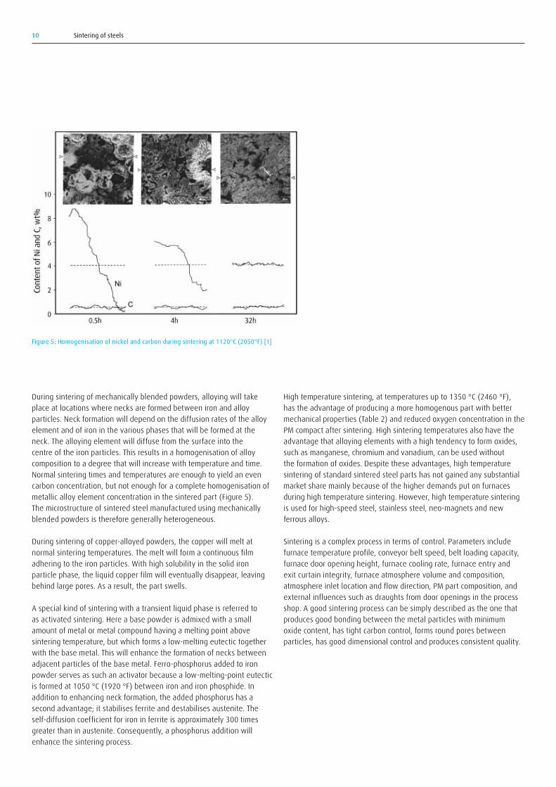
Table 2. Chemical analysis and mechanical properties after sintering in 90/10 N₂/H₂ atmosphere of Astaloy CrM at 1120 °C (2050 °F) and 1250 °C (2300 °F) [4]
Sintering temperature
Chemical analysis Mechanical properties
°C (°F) 1120 (2050)1250 (2280)
C [wt%]0.320.30
O [wt%]0.120.01
Tensile strength [MPa]8601010
Yield stress, 0.2% [MPa]580610
Hardness, [HV10]240250
Area contraction [%]1.41.5
Impact energy [J]1928

Sintering of steels12
machine. Debinding and sintering are the last steps in the production of a MIM component.
MIM works best with powders with particle sizes up to approximately 20μm.Anewerdevelopmentistheuseofveryfinepowders(<5μm),for production of, for example, micro-mechanical devices, medical devices and military and aircraft appliances. Common powders for MIM are stainless steel and ceramics including cemented carbides.
There are several different debinding methods, but here only thermal debinding will be described. The principles of debinding of cold pressed green parts also apply to MIM, but there are some matters specific to MIM to consider for the atmosphere control. The most important is related to the low green body density and associated very high binder content – of the order 40–60% – in the MIM part. The type of binder is also different from that for cold pressing and consists typically of a thermoplastic, a lubricant, a wax, a dispersant and/or a solute. The thermoplastic – commonly polystyrene, polypropylene or polyacetate – is the backbone of the binder, keeping the moulded shape intact until sintering. The lubricant is the same as for cold pressed parts – Acrawax or zinc stearate. Stearic acid is common as a dispersant. Due to the
from sintering temperature to result in hardened parts with martensitic microstructure, is a development that produces such improved properties.
The accuracy of dimensional control is dependent on the direction of the dimension during cold pressing – axial or in the transverse. Close tolerances can be kept if a calibration (or re-pressing) step is included after sintering.
Specifications of standardised sinter steels can be found in the standard ISO 5755 (MPIF Standard: 35).
2.4 Metal injection moulding
Metal injection moulding (MIM) is a production method using the injection moulding process, which has been used by the polymer industry for a long time. Sometimes the term powder injection moulding (PIM) is used to include both MIM and ceramic injection moulding (CIM). MIM uses powders intermixed with a binder. The mixture forms a semi-liquid slurry that is pressed into components in an injection moulding
a) b) c)
d) e) f)
Figure 6: Examples of sintered parts: a) sinter-hardened gear and pinion for automotive application [courtesy of MG MiniGears], b) sinter-hardened synchroniser hub [courtesy of PMG Füssen GmbH], c) sintered camshaft gear [courtesy of AMES SA], d) planetary assembly [courtesy of AMES SA], e) synchronising assembly [courtesy of Höganäs AB], f) planetary carrier [courtesy of Höganäs AB]
Sintering of steels 13
high binder content and to its chemistry, the debinding stage for a MIM compact is more critical than for cold pressed PM compacts.
A consequence of the high binder content is that the debinding step before sintering requires a longer time than debinding of cold pressed PM parts. Two temperature steps may be required for debinding, one at low temperature typically in the range from 150–200 °C (300–390 °F) with the aim of removing water vapour and low molecule weight species, and a second at higher temperature, 450–700 °C (840–1290 °F) – in the same range as for debinding for cold pressed steel parts. Debinding is often carried out as a separate step in a separate furnace. In this way, the debinding can be optimised without the problem of contaminating the atmosphere for the sintering step. After debinding, the part is called a “brown body”.
As for debinding of cold pressed parts, it has been found that either oxidising or highly reducing 100% hydrogen atmospheres yields the most efficient removal of binder [6].
MIM is mostly applied to the mass production of very small parts. A consequence is that loads are small, making batch furnace the best option in many cases. When debinding and sintering are carried out in a continuous furnace, the risk of contamination of the sintering zone atmosphere is greater than for sintering of cold pressed parts due to the high amount of binder vapours that have to leave through the furnace entry. The high degree of shrinkage, typically 20%, during sintering – because of the low brown body density – has to be taken into account when dimensioning the MIM green body.
Much of the MIM production is in stainless steel, e.g. gears for electric tooth brushes, and advanced alloys such as titanium for hip joints, but MIM parts in steel are increasing.
2.5 Heat treatment of sintered parts
Sintered parts can be heat treated with the same processes, in the same type of furnaces and with the same atmospheres as those used for solid wrought steel parts. However, the porosity of sintered steel parts affects the heat treatment result mainly in two ways. First, it influences the heat conductivity and therefore cooling rates upon hardening. Second, it influences the transport of gases in thermochemical surface hardening processes such as carburising, carbonitriding, nitriding and nitrocarburising.
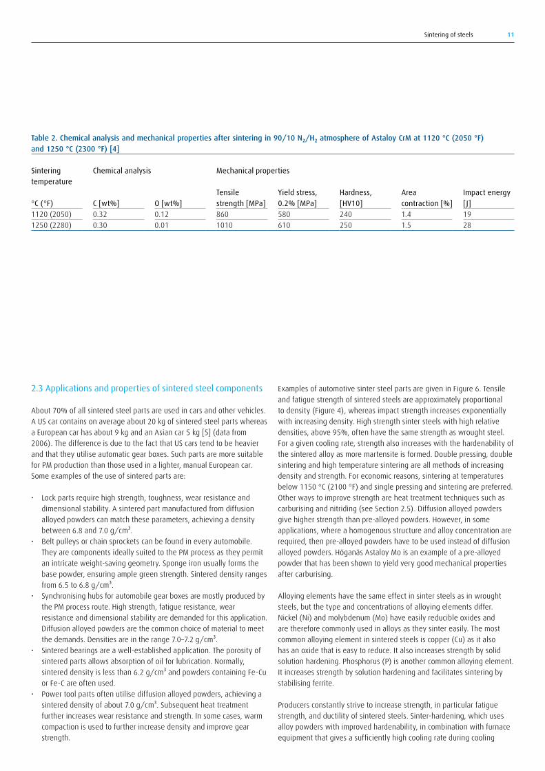
2.5.1 Carburising and carbonitridingIn all atmospheric thermochemical surface hardening methods, there will be gas transport through open porosity. This will lead to mass transfer of carbon and/or nitrogen not only at the surface, but also within the PM compact. The total surface area in contact with the carburising or nitriding atmosphere will be much greater than for fully dense steel. The mass transfer of carbon will accordingly be much greater. Carburising and nitriding depths will, for a given temperature/time process cycle, be greater than for wrought fully dense steels. For densities below 6.65 g/cm³, this leads to a large scatter in carburising depth. However, the depth will be about the same as for dense steels for densities above 7.2 g/cm³ where there is mainly closed porosity. Figure 7 illustrates the effect of density on the case depth after carbonitriding. Alloying with sulfur is found to decrease the open porosity, thereby decreasing the carburising depth [7].
The pore size also has an effect on the carburising depth. It has been found that a well-defined case depth is obtained if the majority of pores have diameters less than 1 mm [8].
0
0.2
0.4
0.6
0.8
1
1.2
6 6.5 7 7.5
Dens
ity, g
/cm
3
Depth for wroughtfully dense steel
Case depth, mm
Figure 7: Effect of density on case depth for a carbonitrided PM steel; carbonitriding at 870°C (1596°F) for 30 minutes, oil quenched [7]

Sintering of steels14
2.5.3 Steam treatmentAblackFe₃O₄ironoxidecoatingwithtypicalthickness5μmcanbeproduced by performing a heat treatment at 450–590 °C (840–1094 °F) for about an hour in a water vapour atmosphere according to the following reaction:
3Fe+4H₂O→Fe₃O₄+4H₂
with the equilibrium constant:
K=P⁴H₂/P⁴H₂O
TheratioK=P⁴H₂/P⁴H₂O has to be adjusted correctly in order for the desired oxide to form as illustrated in Figure 8.
The oxide helps to close open surface porosity and gives an improved atmospheric corrosion resistance. The process is normally carried out as a separate treatment after sintering in batch or continuous furnaces. However, efforts have been made to incorporate the oxidation step into a sintering furnace by designing a separate oxidation zone supplied with humidified nitrogen after a first cool-down zone [12].
The density may vary from one point to another in one single part depending on part geometry, cold pressing and sintering conditions. This can lead to varying carburising depths around the part.
Lubricant or cleaning water vapours coming out through an open pore system can degrade the carburising atmosphere composition. It is recommended that enriching propane or natural gas for carbon potential control is first supplied only when the atmosphere reaches a stable composition. Sintered parts should be thoroughly cleaned before heat treatment.
Vacuum carburising avoids the contaminating effect of lubricant vapours. As for atmospheric carburising, the degree of open porosity has a strong effect on carburising depths. At densities above 7.3 g/cm³, the results are close to those obtained on wrought steels. The sensitivity to open porosity is higher when acetylene is used as carburising agent compared to when propane is used [9].
2.5.2 Nitriding and nitrocarburisingNitriding depth is dependent on density in a similar way to carburising. With plasma nitriding, the effect caused by open porosity is reduced. Surface nitriding depth decreases with decreasing porosity. As for carburising, sulfur addition to the PM alloy reduces the interconnected porosity, resulting in thinner nitrided layers [10].
Thorough cleaning is especially important before nitriding or nitrocarburising because surface contaminations will stop diffusion, leading to uneven nitriding/nitrocarburising results.
% H2O
Tem
pera
ture
, °C
Tem
pera
ture
, °F
Fe3O4
FeO
Austenite
Ferrite
% H2
200 400
600
800
1000
1200
1400
1600
1800
2000
2200
2400
400
600
800
1000
1200
0102030405060708090100
0 10 20 30 40 50 60 70 80 90 100
Figure 8: Fe-oxide equilibrium [11] Figure 9: Cross-sectional view of the principles of an HIP installation.
End closure
Wire-wound vessel
Furnace insulation mantle
Furnace heater
Furnace workload support and bottom insulation
Thermocouple feedthrough
Power feedthrough
Sintering of steels 15
2.6 HIP – hot isostatic pressing
(The following description is to a major extent taken from the HIP chapter in the book Steel and its Heat Treatment [13].) In hot isostatic pressing, simultaneous high pressure and high temperature is used for the production of parts from metal powders. The method is also used in other applications that can take advantage of high pressure and temperature, for example, the sealing of castings and the production of composite materials.
In addition to the production of conventional steels of a higher standard than casting enables, the technology is used to produce alloys that cannot be produced using normal melting metallurgy. Metal matrix composites, where the strengthening phase is provided by various ceramic materials, is an example of this. HIP technology is used in both the manufacture of semi-finished products, such as bars and tubes, and of end products with final shape as well as in heat treatment and coating processes for the improvement of properties in products manufactured by more conventional technology.
The equipment, see Figure 9, comprises a furnace chamber enclosed in a pressure vessel adapted to withstand extremely high pressure and which can also be fully evacuated to vacuum levels.
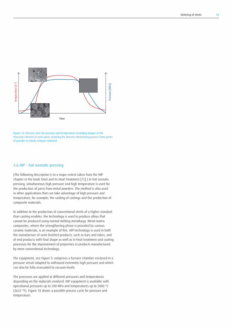
The processes are applied at different pressures and temperatures depending on the materials involved. HIP equipment is available with operational pressures up to 200 MPa and temperatures up to 2000 °C (3632 °F). Figure 10 shows a possible process cycle for pressure and temperature.
Figure 10: Process cycle for pressure and temperature including images of the structures formed at each point, showing the density-intensifying process from grains of powder to totally compact material
Tem
pera
ture
[C°]
Pres
sure
[MPa
]
Time
Sintering of steels16
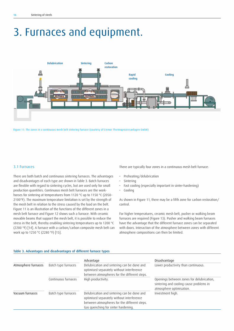
There are typically four zones in a continuous mesh belt furnace:
• Preheating/delubrication• Sintering• Fast cooling (especially important in sinter-hardening)• Cooling
As shown in Figure 11, there may be a fifth zone for carbon restoration/control.
For higher temperatures, ceramic mesh belt, pusher or walking beam furnaces are required (Figure 13). Pusher and walking beam furnaces have the advantage that the different furnace zones can be separated with doors. Interaction of the atmosphere between zones with different atmosphere compositions can then be limited.
3.1 Furnaces
There are both batch and continuous sintering furnaces. The advantages and disadvantages of each type are shown in Table 3. Batch furnaces are flexible with regard to sintering cycles, but are used only for small production quantities. Continuous mesh belt furnaces are the work-horses for sintering at temperatures from 1120 °C up to 1150 °C (2050–2100°F). The maximum temperature limitation is set by the strength of the mesh belt in relation to the stress caused by the load on the belt. Figure 11 is an illustration of the functions of the different zones in a mesh belt furnace and Figure 12 shows such a furnace. With ceramic movable beams that support the mesh belt, it is possible to reduce the stress in the belt, thereby enabling sintering temperatures up to 1200 °C (2200 °F) [14]. A furnace with a carbon/carbon composite mesh belt can work up to 1250 °C (2280 °F) [15].
3. Furnaces and equipment.
Figure 11: The zones in a continuous mesh belt sintering furnace (courtesy of Cremer Thermoprozessanlagen GmbH)
Delubrication Sintering Carbonrestoration
Rapidcooling
Cooling
Table 3. Advantages and disadvantages of different furnace types
Atmosphere furnaces
Vacuum furnaces
Batch type furnaces
Continuous furnaces
Batch type furnaces
AdvantageDelubrication and sintering can be done and optimised separately without interference between atmospheres for the different steps.High productivity.
Delubrication and sintering can be done and optimised separately without interference between atmospheres for the different steps. Gas quenching for sinter hardening.
DisadvantageLower productivity than continuous.
Openings between zones for delubrication, sintering and cooling cause problems in atmosphere optimisation.Investment high.

Sintering of steels 17
Furnaces should have proper systems for temperature, time and atmosphere control. The cooling zone may or may not have forced cooling.
Silicon carbide heating elements can be operated up to 1350 °C (2460 °F). For special purposes at even higher temperatures, molybdenum heating elements are used. Particular problems arise here, notably the readiness with which molybdenum forms a volatile oxide. Molybdenum furnaces therefore must operate in a pure hydrogen atmosphere.
The maintenance of sintering furnaces and especially the control equipment (temperature, gas flow and gas composition sensors) is crucial for maintaining consistent sintering output quality.
The use of batch vacuum sintering furnaces is increasing. They can be designed for different process steps including delubrication, vacuum sintering, and high pressure gas cooling (Figure 14).
MIM furnaces are mostly of the batch type, quite small and often of a bell-type design as shown in Figure 15. The small size is due to the small loads that are typical of MIM production. Continuous furnaces are of the pusher or walking beam types that can withstand the high sintering temperature, over 1300 °C (2370 °F), commonly used in MIM applications. A continuous line with separate walking beam furnaces running in parallel for debinding and sintering has been shown to yield high productivity and stable quality [16].
Figure 12: A continuous mesh belt sintering furnace (courtesy of Abbot Furnace Company)
Figure 13: Pusher sintering furnace with molybdenum heating elements for temperatures up to 1600 °C (2910 °F) (courtesy of Abbot Furnace Company)
Figure 14: (left) Dewaxing and vacuum sintering furnace (courtesy of Seco Warwick), (right) Line of vacuum furnaces for dewaxing, sintering and high pressure sintering (courtesy of ALD Vacuum Technologies GmbH)
Figure 15: Bell-type box furnace for MIM sintering (courtesy of CM Furnaces Inc.)

Sintering of steels18
3.2.2 Methanol equipmentAlthough not so common, methanol may be used as the source for creating carbon-containing atmospheres also for sintering. The equipment required is the same as for carburising atmospheres and includes specially designed methanol injectors and methanol pumps. See reference [18] for details.
3.2 Atmosphere equipment
Equipment for flow control includes:
• Humidifier for nitrogen• Flowtrain• Conventional flow meters or mass flow meters• Flow control valves• Solenoid valves for safety shut-off of flammable gases and normally-
open for nitrogen purge
3.2.1 High-speed gas injection for improved gas homogeneityGas stirring inside the muffle with the gas injection lance (based on the CARBOJET® technology [17]) will significantly improve the stirring and homogeneity of the furnace atmosphere and thereby the quality of the sintered parts. The gas inlet for the lance mounted on a roller hearth furnace is seen in the foreground to the left in Figure 16.
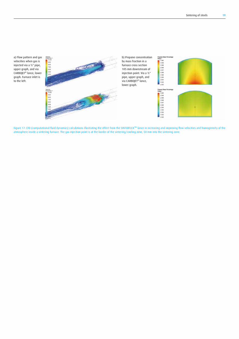
Figure 17a shows flow modelling calculations that illustrate how the use of the CARBOJET® injection lance increases flow velocities. It also improves the homogeneity in the gas composition. This is illustrated for the concentration of propane in Figure 17b. A radical improvement in gas flow velocities and circulation will be achieved up to a distance of approximately one metre from the point of lance installation.
The improved gas circulation obtained with the CARBOJET® lance leads to significant improvements in sintered parts quality, especially with regard to carbon control.
Figure 16: Installation of CARBOJET® effective atmosphere stirring without a fan
Sintering of steels 19
Figure 17: CFD (computational fluid dynamics) calculations illustrating the effect from the SINTERFLEX™ lance in increasing and improving flow velocities and homogeneity of the atmosphere inside a sintering furnace. The gas injection point is at the border of the sintering/cooling zone, 50 mm into the sintering zone.
a) Flow pattern and gas velocities when gas is injected via a ½" pipe, upper graph, and via CARBOJET® lance, lower graph. Furnace inlet is to the left.
b) Propane concentration by mass fraction in a furnace cross section 105 mm downstream of injection point. Via a ½" pipe, upper graph, and via CARBOJET® lance, lower graph.

Sintering of steels20
In order to make a good atmosphere, it is usually necessary to combine atleasttwodifferentgases.N₂/H₂atmospheresareproducedbyfeeding nitrogen and hydrogen through separate flow meters to the furnace. It can also be supplied by thermally cracking ammonia in an external ammonia cracker that yields a 75% hydrogen/25% nitrogen atmosphere. The cracked ammonia can be diluted with an extra supply ofnitrogen.N₂/CO/H₂atmospheresmaybeobtainedfromseparatesupply of the three gases or from methanol, which dissociates to carbon monoxide and hydrogen in the furnace and is diluted with nitrogen to thecorrectcomposition.N₂/CO/H₂atmospherescan,alternatively,beproduced from nitrogen-diluted endothermically generated gas.
An atmosphere supply system consists of three major parts: storage, mixing and inlet to the furnace.
4.1 Nitrogen, argon and hydrogen supply
There are five major forms of supply for nitrogen:
1. Gaseous nitrogen in cylinders2. Liquid nitrogen supplied by truck to the customer container3. Nitrogen produced on-site with cryogenic technology (CRYOSS®)4. Nitrogen from pressure swing adsorption (PSA) units installed on-site at
the facility (ADSOSS®)5. Nitrogen from on-site membrane units installed on-site at the facility
(MEMOSS®)
Furnace atmospheres are supplied to a furnace in two basic ways. The first, referred to here as in-situ generation, is by supplying gases, such as nitrogen, hydrogen and argon, directly to the furnace where they are mixed to create the correct composition. The second is to react components (typically a fuel and air) in an external generator to produce the furnace atmosphere. These two methods can be combined.
External gas generators for endothermic and exothermic gas, monogas and cracked (dissociated) ammonia produce a fixed atmosphere composition. The output flow rate can be varied only within certain limits.
In-situ methods can create widely varying atmosphere compositions and the flow can also be adapted to needs at any time. The gases and methanol(thatcanbethermallycrackedtoformaCO/H₂mixture)are supplied from separate sources and are piped separately to the furnace in which the gases are mixed, reacted and synthesised. Specific advantages related to the use of synthetic atmospheres are:
• Flow rate can be adapted and minimised to the true need of the furnace and the process.
• Gas mixture can be adapted to any ratio according to the need of the alloy and the process.
• Short start-up and conditioning.• Maintenance and supervision are minimised.• Gas production reliability is improved compared to the use of
generators.• Quality and productivity can be improved by using the flexibility of
mixing and flow rate control.• Increased safety.
Figure 18: Storage tank and vaporiser for liquid nitrogen Figure 19: PSA (pressure swing adsorption); ADSOSS®.
4. Atmosphere generation, gas supply.
Sintering of steels 21
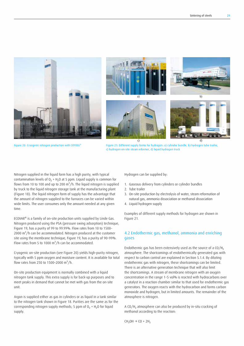
Figure 20: Cryogenic nitrogen production with CRYOSS® Figure 21: Different supply forms for hydrogen: a) cylinder bundle, b) hydrogen tube trailer, c) hydrogen on-site steam reformer, d) liquid hydrogen truck
Nitrogen supplied in the liquid form has a high purity, with typical contaminationlevelsofO₂+H₂Oat5ppm.Liquidsupplyiscommonforflows from 10 to 100 and up to 200 m³/h. The liquid nitrogen is supplied by truck to the liquid nitrogen storage tank at the manufacturing plant (Figure 18). The liquid nitrogen form of supply has the advantage that the amount of nitrogen supplied to the furnaces can be varied within wide limits. The user consumes only the amount needed at any given time.
ECOVAR® is a family of on-site production units supplied by Linde Gas. Nitrogen produced using the PSA (pressure swing adsorption) technique, Figure 19, has a purity of 99 to 99.99%. Flow rates from 10 to 1500–2000 m³/h can be accommodated. Nitrogen produced at the customer site using the membrane technique, Figure 19, has a purity of 90–99%. Flow rates from 5 to 1000 m³/h can be accommodated.
Cryogenic on-site production (see Figure 20) yields high-purity nitrogen, typically with 5 ppm oxygen and moisture content. It is available for total flow rates from 250 to 1500–2000 m³/h.
On-site production equipment is normally combined with a liquid nitrogen tank supply. This extra supply is for back-up purposes and to meet peaks in demand that cannot be met with gas from the on-site unit.
Argon is supplied either as gas in cylinders or as liquid in a tank similar to the nitrogen tank shown in Figure 18. Purities are the same as for the correspondingnitrogensupplymethods;5ppmofO₂+H₂Oforliquidsupply.
a) b)
c) d)
Hydrogen can be supplied by:
1. Gaseous delivery from cylinders or cylinder bundles2. Tube trailer3. On-site production by electrolysis of water, steam reformation of
natural gas, ammonia dissociation or methanol dissociation4. Liquid hydrogen supply
Examples of different supply methods for hydrogen are shown in Figure 21.
4.2 Endothermic gas, methanol, ammonia and enriching gases
EndothermicgashasbeenextensivelyusedasthesourceofaCO/H₂ atmosphere. The shortcomings of endothermically generated gas with respect to carbon control are explained in Section 5.1.4. By diluting endothermic gas with nitrogen, these shortcomings can be limited. There is an alternative generation technique that will also limit the shortcomings. A stream of membrane nitrogen with an oxygen concentration in the range 1–5 vol% is reacted with hydrocarbons over a catalyst in a reaction chamber similar to that used for endothermic gas generators. The oxygen reacts with the hydrocarbon and forms carbon monoxide and hydrogen, but in limited amounts. The remainder of the atmosphere is nitrogen.
ACO/H₂atmospherecanalsobeproducedbyin-situcrackingofmethanol according to the reaction:
CH₃OH→CO+2H₂

Sintering of steels22
Acetylene used in vacuum carburising is supplied in special cylinders that ensure safe handling.
Safety instructions with respect to handling, storage, supply and use must be followed for all gases. Appropriate safety data sheets can be obtained from Linde Gas.
4.3 Examples of supply solutions
Figure 22 shows two different options for nitrogen/hydrogen installations, the first with separate individual mixing panels for each furnace and the second with the same premix of nitrogen/hydrogen supplied to several furnaces. Hydrocarbons may be added for carbon potential control.
Figure 23 shows an example cylinder supply for both carbon monoxide and hydrogen. Dissociated methanol and endogas are alternative sourcesforCO/H₂supply.Asforthenitrogen/hydrogeninstallation,hydrocarbons may be added for carbon potential control.
4.4 Atmosphere flow rate and flow configuration
The amount of gas supplied to the sintering furnace should be sufficient to create a gas flow rate that limits the ingress of oxygen (air) at furnace entry and exit. This critical flow rate increases with:
• Increased belt loading• Increased entry and exit opening areas• Increased sintering temperature• Draughts created by open doors, windows, fans, etc.• Increased exhaust draught
By mixing cracked methanol with nitrogen, it is possible to produce awiderangeofN₂/CO/H₂compositionssuchasthoseobtainedbyendothermic gas, exothermic gas or monogas generators. Methanol should be introduced into the furnace at a place where the temperature exceeds 800 °C (1472 °F). At lower temperatures, other cracking reactionsmayproduceunwantedby-products–CH₄,CO₂,H₂Oandsoot.The cracking of methanol can be improved by disintegrating the liquid methanol stream into droplets by the use of a special atomising spray nozzle or by the use of a methanol vaporiser. Methanol is supplied in liquid form and stored in steel tanks.
Enriching gas for carbon potential control may be natural gas or propane. Natural gas, when available, is supplied directly via a natural gas pipeline network. Propane is delivered in cylinders or cylinder bundles for small or moderate requirements, and in tanks for large consumers.
Propane liquefies at relatively low pressure, which means that the gas is mainly in liquid form in the cylinders or the tanks.
Ammoniamaybeusedforproductionofa25%N₂/75%H₂atmosphereby thermal cracking over a catalyst according to the reaction:
2NH₃→N₂+3H₂
This atmosphere is normally diluted with nitrogen to a hydrogen concentration of the order 5 to 15 vol%. Ammonia is also used as the nitrogen source for carbonitriding, nitriding and nitrocarburising.
Ammonia is, as for propane, delivered in cylinders or cylinder bundles for small or moderate needs, and in bulk for large consumers. Ammonia also liquefies at relatively low pressure with the same consequences as for propane.
a)
b)
Figure 22: Nitrogen/hydrogen installations with a) gas mixing at each furnace and b) a premixed gas for all furnaces
Figure 23: Gas installation with nitrogen, hydrogen and carbon monoxide
CRYOSS®
H₂
To furnace
To furnace
N₂ back-up
CRYOSS®
H₂
Gas mixer H₂/N₂To furnace
To furnace
N₂ back-up
CRYOSS®
H₂CO
Gas mixer CO/H₂/N₂
To furnace
To furnace
N₂ back-up

Sintering of steels 23
the CARBOJET® lance (see Section 3.2) this problem is counteracted, improving gas circulation and mixing.
The volume of gases that leave at the entry and exit, and possibly through the exhaust duct and leaks, is determined by the pressure differential between the front and rear of the furnace. Figure 25 shows this for a typical continuous sintering furnace. In order to avoid atmosphere degradation from air entering the furnace, it is important to ensure that there are no draughts e.g. from doors into the workshop close to the furnaces.
The amount of gas required for sintering is approximately 0.3–0.5 m³/kg of sintered steel. This means that the gas flow rate required is of the order of 25 to 100 m³/hour for typical furnaces and furnace loads.
When starting up a new furnace or when changing atmosphere composition, it is essential to allow sufficient furnace volumes of gas and sufficient time for proper conditioning. For a new furnace or a furnace that has been on standby for a long time, humidity trapped in the furnace ceramics has to be dried out. This drying procedure can be shortened if there are valves along the furnace that allow efficient atmosphere purging.
Gas analysis profiling along a sintering furnace is a way to evaluate the flow configuration and to ensure that it is correct. Figures 26a and 26b show examples of analysis profiles. Good and bad atmosphere conditions for sintering of Astaloy CrL and CrM are shown. Flow modelling is another tool that can help optimise gas inlet design and the amount of gas used at the different inlet positions. Some examples of such simulations are given in Section 3.2.
Figure 24 shows where atmosphere leakage can occur around a furnace door.
It is recommended that the atmosphere flow used is slightly more than the minimum flow required to maintain stable atmosphere conditions. When using physical curtains in order to reduce the amount of oxygen ingress, they should be placed as close as possible to muffle openings. Curtains placed at the exit end will limit air inflow and assist in directing flows towards the entry.
Not only the flow rate itself, but also the flow configuration is of importance. The main atmosphere supply is normally made at the interface between the hot sintering zone and the cold cooling zone. In this way, the risk of delubrication gaseous products from the preheating zone degrading the sintering zone atmosphere is minimised. Hydrocarbons diluted by nitrogen must be injected directly in the sintering zone. Proper atmosphere flow direction is very important in order to avoid penetration of the hydrocarbons into the cooling zone where it could form soot or cause oxidation. If an oxidising atmosphere, e.g. humidified nitrogen, is used, it should be supplied directly into the delubrication zone. Extra nitrogen may be supplied into the cooling zone to ensure that the oxygen concentration is low enough to avoid oxidation.
With proper atmosphere inlet locations and injector design, it is possible, to some extent, to create an atmosphere profile suitable for the different steps (delubrication, sintering and cooling).
In a normal sintering furnace, there are no atmosphere circulation fans that help to create an even atmosphere composition. So there is a risk that the atmosphere composition will vary between different positions, for instance, between the top and the bottom of part loads. By installing
Figure 24: Schematic illustration of areas of atmosphere leakage at furnace door [19] Figure 25: Flow out of the entry as a function of the pressure difference between front and rear of the furnace [19]
Fan to coolworker or parts
Exhaust damper
Nitrogen purge flowDoor
opening
Purgeflow
Doorleak
Vestibule opening
1.00
1.10
1.20
1.30
1.40
1.50
1.60
1.70
1.80
1.90
0 1 2 3 4 5
Flow
out
of f
urna
ce fr
ont,
rela
tive
valu
e
Pressure bias between front and rear of furnace, mm H2O

Sintering of steels24
Figure 26: CO and dew point profiles along a sintering furnace showing a) good and b) poor conditions. Dew point requirements were –28 °C (–18 °F) for Astaloy CrL and –32 °C (–26 °F) for Astaloy CrM in N/H₂ atmospheres with 3.7 and 2.7 vol% H₂ respectively at the sintering temperature 1120 °C (2050 °F). Please observe the different scales for dew point [20]
–60–55–50–45–40–35–30–25–20–15–10–50510 50
40
30
20
10
0
–10
–20
–30
–40
–50
–60
–70–750
1
2
3
4
5
6
7
Dew
poi
nt
CO co
ncen
tratio
n, %
Dew point% CO
Atmosphere: 3.7 vol% H2 in N2
a) Good conditions
Distance from furnace inlet, arbitrary unit
°C °F
–30
–20
–10
0
10
20
40
30
100
80
60
40
20
0
–200
1
2
3
4
5
6
7
Dew
poi
nt
CO co
ncen
tratio
n, %
Atmosphere: 2.7 vol% H2 in N2
b) Poor conditions
Distance from furnace inlet, arbitrary unit
°C °F
Dew point% CO

Sintering of steels 25
Sintering of steels26
In continuous mesh belt furnaces, there is inter-zonal atmosphere flow and intermixing between the different zones. It may be understood, therefore, that fulfilling the requirements of the different sintering steps will require a compromise solution prioritising critical functions. In furnaces with doors between zones, e.g. in pusher furnaces or in vacuum batch furnaces, it is easier to adapt the atmosphere solution to the different steps. Proper atmosphere control will lead to sintered parts having the right mechanical properties, dimensional accuracy and surface appearance.
5.1 Theory and principles
5.1.1 The delubrication – preheating stepThe green body entering the sintering furnace typically contains 0.5–1.5 wt% lubricants, the most widely used being zinc stearate and ethylene bis stearamide (EBS), the latter commonly known by the trade name Acrawax. When added to the powder, the lubricant particles aresphericalwithatypicalmeandiameterof10–30μm[21].Duringpressing, a fluid lubricant film is formed between powder particles which then sets again on ejection from the die. This lubricant film has to be eliminated during the heat-up in the first zone of the sintering furnace. If not removed, the lubricant will decompose and leave carbon in the form of soot inside the sintered body, thus detrimentally affecting strength and toughness.
The sequence of events leading to lubricant removal is as follows: melting, vapour formation, vapour transport by convection and diffusion through the pores, pyrolysis, possibly oxidation or hydrogenation of vapour species, and finally transport of the vapours out of the furnace with the help of the atmosphere flow in the furnace.
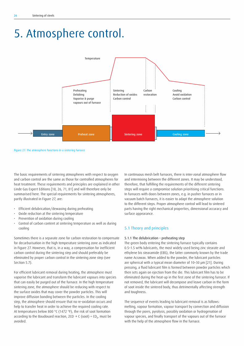
The basic requirements of sintering atmospheres with respect to oxygen and carbon control are the same as those for controlled atmospheres for heat treatment. These requirements and principles are explained in other Linde Gas Expert Editions [18, 26, 71, 81] and will therefore only be summarised here. The special requirements for sintering atmospheres, partly illustrated in Figure 27, are:
• Efficient delubrication/dewaxing during preheating• Oxide reduction at the sintering temperature• Prevention of oxidation during cooling• Control of carbon content at sintering temperature as well as during
cooling
Sometimes there is a separate zone for carbon restoration to compensate for decarburisation in the high temperature sintering zone as indicated in Figure 27. However, that is, in a way, a compensation for inefficient carbon control during the sintering step and should preferably be eliminated by proper carbon control in the sintering zone step (see Section 5.7).
For efficient lubricant removal during heating, the atmosphere must vaporise the lubricant and transform the lubricant vapours into species that can easily be purged out of the furnace. In the high temperature sintering zone, the atmosphere should be reducing with respect to the surface oxides that may cover the powder particles. This will improve diffusion bonding between the particles. In the cooling step, the atmosphere should ensure that no re-oxidation occurs and help to transfer heat in order to achieve the required cooling rate. At temperatures below 800 °C (1472 °F), the risk of soot formation accordingtotheBoudouardreaction,2CO→C(soot)+CO₂,mustbeavoided.
5. Atmosphere control.
Figure 27: The atmosphere functions in a sintering furnace
Preheating DelubingVaporise & purge vapours out of furnace
SinteringReduction of oxidesCarbon control
Temperature
CoolingAvoid oxidationCarbon control
Carbonrestoration
Entry zone Cooling zonePreheat zone Sintering zone
Sintering of steels 27
during heating shows that the peak concentrations of the different vapours are moved to higher temperatures with increased heating rate. A heating rate that is too high can lead to the lubricant vapours flowing out from the pores of the green compact to decompose and deposit carbon as soot, graphite or polymeric carbon residues on the surfaces of the parts. The pore system would then become plugged, leading to a pressure increase from contained vapour. In the worst case, this can cause cracks, blisters or deformation of the PM body. This risk increases with increased green density of the compact because the fraction of pores that are filled with lubricants will be higher.
The fraction of pores filled with lubricant is nearly saturated for green densities in the range 7.4 to 7.5 g/cm³ [21]. Rapid heating of such saturated pore structures may cause volcanic eruptions, as vapour is formed beneath the porous surface. An open pore system will favour successful delubrication. The delubrication must therefore be completed before actual sintering starts as the degree of open porosity will otherwise decrease and retard delubrication.
There are conflicting reports as to whether the most efficient delubrication is obtained in oxidising, humidified atmospheres, or in reducing, dry hydrogen atmospheres. First, some results supporting the reducing atmosphere approach are presented followed by some supporting the oxidising atmosphere approach.
Figure 29 shows thermo-gravimetric measurements for the weight loss during delubrication of a stainless steel green PM body in different atmospheres. It shows that air is effective up to about 500 °C (930 °F), but above that temperature there is a weight increase caused by oxidation of the PM compact. Delubrication in neutral nitrogen is, according to the thermo-gravimetric data, less effective than air up to 500 °C (930 °F), but more effective above that temperature because oxidation and resultant weight increase is inhibited. A weight increase
For proper removal to occur, the following requirements need to be fulfilled:
• A slow heating rate in the temperature range 400–600 °C (750–1110 °F)
• An atmosphere composition chosen so that lubricant vapour species are reacted into species that are volatile and can be purged out of the furnace
• An atmosphere flow direction set so that lubricant vapour products are effectively removed from the furnace at the entry
• An atmosphere flow velocity towards the entry that is high enough to efficiently transport vapours away and to avoid any stagnant vapour layer forming at the part surfaces
In a statistical study, it was found that the major factor influencing delubrication was the heating rate. Atmosphere composition (humidity, hydrogen content) was found to be the second most important factor, and gas flow rate the least important [22-23].
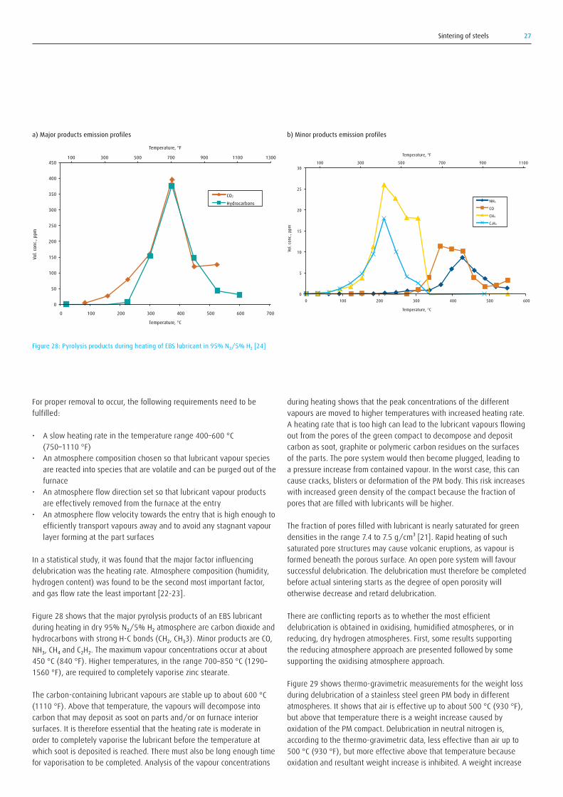
Figure 28 shows that the major pyrolysis products of an EBS lubricant duringheatingindry95%N₂/5%H₂atmospherearecarbondioxideandhydrocarbonswithstrongH-Cbonds(CH₂,CH₃3).MinorproductsareCO,NH₃,CH₄andC₂H₂.Themaximumvapourconcentrationsoccuratabout450 °C (840 °F). Higher temperatures, in the range 700–850 °C (1290–1560 °F), are required to completely vaporise zinc stearate.
The carbon-containing lubricant vapours are stable up to about 600 °C (1110 °F). Above that temperature, the vapours will decompose into carbon that may deposit as soot on parts and/or on furnace interior surfaces. It is therefore essential that the heating rate is moderate in order to completely vaporise the lubricant before the temperature at which soot is deposited is reached. There must also be long enough time for vaporisation to be completed. Analysis of the vapour concentrations
Figure 28: Pyrolysis products during heating of EBS lubricant in 95% N₂/5% H₂ [24]
0
50
100
150
200
250
300
350
400
450
0 100 200 300 400 500 600 700
CO2 Hydrocarbons
Temperature, °C
Vol.
conc
., pp
m
Temperature, °F
100 300 500 700 900 1100 1300
0
5
10
15
20
25
30
Vol.
conc
., pp
m
Temperature, °C
Temperature, °F
NH3
CO
CH4
C2H4
0
100 300 500 700 900 1100
100 200 300 400 500 600
a) Major products emission profiles b) Minor products emission profiles

Sintering of steels28
delubricationbothindryandhumidified95N₂/5H₂atmospheresandfound, contrary to the findings of Phillips, that there was no appreciable effect on the delubrication. However, they found that the carbon monoxide maximum appearing at a temperature of about 800 °C (1470 °F), as shown in Figure 30, doubles in magnitude in the presence of water and is shifted to a slightly higher temperature. This carbon monoxide maximum is the result of oxidation of carbon in the presence of water vapour and shows that water vapour plays a role in reactions with the lubricant vapours. Baum et al also tested delubrication in pure nitrogen and found a big difference compared to delubrication in a hydrogen-containing atmosphere. The second carbon monoxide peak (Figure 30) appeared for nitrogen at about 725 °C (1340 °F) compared to 850 °C (1560 °F) for nitrogen/hydrogen and reached a level one order of magnitude higher than for nitrogen/hydrogen.
Despite these findings, it is a common practice to use oxidising atmospheres in the delubrication step. Amongst others Nayar [29], Madsac [30] and Saha [22-23] claim that humidified oxidising atmospheres, produced, for instance, by bubbling a nitrogen stream through a heated water bath, result in efficient delubrication. The oxidising delubrication atmosphere will oxidise the carbon in the lubricanthydrocarbonsintocarbondioxide(CO₂)andcarbonmonoxide(CO)andthehydrogen(H₂)intowatervapour(H₂O).Airoroxygengives less good delubrication results partly due to the risk of excessive oxidation of the powder. The lubricant vapour will, together with the oxidising atmosphere, where oxygen is in air or water vapour or carbon dioxide, combust with a resulting temperature increase.
The oxidising approach has been applied by several furnace manufacturers who have developed systems that inject a fuel gas and air into special burners located in the delubrication zone. The combustion both generates heat and produces an oxidising atmosphere. Lubricant vapours as well as the reducing atmosphere components, hydrogen and
is registered above approximately 900 °C (1650 °F). This is caused by nitrogen pick-up in the stainless steel. By using inert argon, that nitrogen pick-up is avoided, but the delubrication effect in argon is inferior to that in nitrogen at temperatures below that where nitriding occurs in nitrogen. For regular steels, the nitrogen pick-up will not occur.
According to the thermo-gravimetric data, the use of pure hydrogen produces the best delubrication effect. (This is analogous to experience in lubricant removal from the surface of steel strip coils during annealing [26].) That reducing hydrogen atmospheres give the best delubrication is supported by results from studies by, amongst others, Phillips and Renowden [25, 27, 28]. Comparing two lubricants, Phillips found that less hydrogen was required for complete delubrication of Acrawax than fordelubricationofzincstearate,15%H₂comparedto50%H₂,andlowertemperature, 550 °C (1020 °F) compared to 850 °C (1560 °F) [25].
Suggested reasons for the beneficial effect from hydrogen are:
• Its small molecule can easily enter small pores and hydrogenate the C-H bonds in the lubricants, thereby improving volatilisation and removal of the binder.
• Its thermal conductivity is the highest of all gases and this leads to faster heat transfer at the surface/atmosphere interface and improved heat conductivity within the PM body. This explanation is supported by the fact that helium, with similar physical properties to hydrogen, yields about the same delubrication at low temperatures [25].
Phillips reported that in delubrication tests of Acrawax with nitrogen/hydrogen atmospheres, humidity had a negative effect [25]. It was found that for an addition of 1% water vapour, a hydrogen concentration of 30% was required, whereas for a dry atmosphere only 15% hydrogen was required for efficient lubricant removal. Baum et al [24] tested
Figure 29: Weight changes during heating in different atmospheres for a stainless steel PM body containing an organic lubricant [25]
Figure 30:Product emission profiles of pyrolysis products between 200 °C (390 °F) and 850 °C (1560 °F) in a dry 95% N₂/5% H₂ atmosphere [24]
Temperature, °C
Temperature, °F
Wei
ght l
oss,
%
0.0
0.1
0.2
0.3
0.4
0 400 800 1200200 600 1000
200 600 1000 1400 1800 2200
H2
N2
Ar
Air
0
100
200
300
400
500
600
700
800
900
1000
0
200
400
600
800
1900
1200
1400
1600
1800
0
50
100
150
200
250
300
350
400
450
0 20 40 60 80 100 120
Tem
pera
ture
Vol c
onc.
, ppm
Time, min
°C °F
CO2 Hydrocarbon CO Temperature

Sintering of steels 29
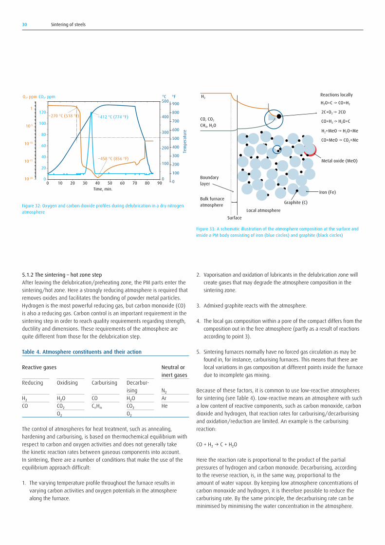
It is recommended that 90% of the gas flow should exit at the furnace entry with the remaining 10% flowing out of the exit from the cooling zone [32]. The point in the preheat zone where lubricant removal is complete changes with loading, size of parts, belt speed, part geometry, lubricant type, lubricant amount and green density. Although not industrially applied, it would be possible to develop a system that monitors the delubrication sequence. It could be incorporated into a closed loop atmosphere control system that would respond to variations in delubrication caused by the different influencing factors. Oxygen probe and carbon dioxide analysis has been shown to precisely monitor the delubrication process as shown in Figure 32. The oxygen analysis results shown in Figure 32 were found using a heated oxygen probe positioned in an external heated cabinet. The drastic drop in oxygen concentration at about 300 °C (570 °F) is caused by the reaction between hydrocarbon vapours from delubrication and oxygen in the oxygen probe cabinet. One possible such reaction is:
2CH₄+4O₂→2CO₂+4H₂O
The oxygen profile in Figure 32 is therefore the inverse of the profiles of the carbon- and hydrocarbon-containing species, especially of hydrocarbons. This is in agreement with the carbon dioxide profile in Figure 30 and with other suggestions for controlling the delubrication stepbyanalysisofalternativelyH₂andCO,ofCH₄,orofCO₂combinedwith CO and C-H analysis [24, 33].
carbon monoxide, flowing out of the sintering zone will be heated and oxidised. The combustion creates an intense gas circulation which helps to purge the lubricant vapours out of the furnace, and the temperature increases to approximately 600 °C (1110 °F). This technique is called “rapid burn off” (RBO) and is claimed to have the advantage that the length of the delubrication furnace zone can be reduced. One such system contained in a separate module connected to the furnace entry is the ADS system manufactured by Gasbarre Products Inc. shown in Figure 31. QDP, Quality Delube Process, or LBT, Lubricant Burner Technology, and CAT-Dewax, a system with an in-situ catalytic combustion chamber, are similar systems marketed by Abbot Furnace Company and Cremer Furnaces respectively. It is claimed that all the oxygen will be bound as carbon monoxide, carbon dioxide and water vapour, thus no free oxygen is present and therefore oxidation of the PM part will be limited [29, 31]. The RBO technique was developed for sintering in endothermic or exothermic generator-based atmospheres but is also applied for nitrogen/hydrogen atmospheres.
In practice, a disadvantage with the RBO technique is that some oxidation of the PM part will occur. This is less detrimental for steels having alloying elements forming oxides that are fairly easily reduced in the later sintering stage. A second drawback with the RBO technique is that there is a risk that the atmosphere composition in the sintering zone will be degraded by mixing between the delubrication and sintering atmospheres. This will negatively affect carbon control, especially for lean nitrogen/hydrogen sintering atmospheres that have limited buffering capacity.
In many, probably most, sintering installations, there is no special, separately controlled, atmosphere composition in the delubrication zone, but one with essentially the same composition as the one in the sintering zone.
Figure 31: Sintering line with the integrated ADS – Accelerated Delube Station, seen as the second left module in the picture (courtesy of Gasbarre Products Inc.)
Sintering of steels30
5.1.2 The sintering – hot zone stepAfter leaving the delubrication/preheating zone, the PM parts enter the sintering/hot zone. Here a strongly reducing atmosphere is required that removes oxides and facilitates the bonding of powder metal particles. Hydrogen is the most powerful reducing gas, but carbon monoxide (CO) is also a reducing gas. Carbon control is an important requirement in the sintering step in order to reach quality requirements regarding strength, ductility and dimensions. These requirements of the atmosphere are quite different from those for the delubrication step.
Table 4. Atmosphere constituents and their action
Reactive gases Neutral or inert gases
Reducing
H₂CO
Oxidising
H₂OCO₂O₂
Carburising
COCnHm
Decarbur-isingH₂OCO₂O₂
N₂ArHe
The control of atmospheres for heat treatment, such as annealing, hardening and carburising, is based on thermochemical equilibrium with respect to carbon and oxygen activities and does not generally take the kinetic reaction rates between gaseous components into account. In sintering, there are a number of conditions that make the use of the equilibrium approach difficult:
1. The varying temperature profile throughout the furnace results in varying carbon activities and oxygen potentials in the atmosphere along the furnace.
2. Vaporisation and oxidation of lubricants in the delubrication zone will create gases that may degrade the atmosphere composition in the sintering zone.
3. Admixed graphite reacts with the atmosphere.
4. The local gas composition within a pore of the compact differs from the composition out in the free atmosphere (partly as a result of reactions according to point 3).
5. Sintering furnaces normally have no forced gas circulation as may be found in, for instance, carburising furnaces. This means that there are local variations in gas composition at different points inside the furnace due to incomplete gas mixing.
Because of these factors, it is common to use low-reactive atmospheres for sintering (see Table 4). Low-reactive means an atmosphere with such a low content of reactive components, such as carbon monoxide, carbon dioxide and hydrogen, that reaction rates for carburising/decarburising and oxidation/reduction are limited. An example is the carburising reaction:
CO+H₂→C+H₂O
Here the reaction rate is proportional to the product of the partial pressures of hydrogen and carbon monoxide. Decarburising, according to the reverse reaction, is, in the same way, proportional to the amount of water vapour. By keeping low atmosphere concentrations of carbon monoxide and hydrogen, it is therefore possible to reduce the carburising rate. By the same principle, the decarburising rate can be minimised by minimising the water concentration in the atmosphere.
Figure 32: Oxygen and carbon dioxide profiles during delubrication in a dry nitrogen atmosphere
Figure 33: A schematic illustration of the atmosphere composition at the surface and inside a PM body consisting of iron (blue circles) and graphite (black circles)
0 10 20 30 40 50 60 70 80 900010-20
10-15
10-10
10-5
1
40
20
60
80
100
120
100
200
300
400
500
0
100
200
300
400
500
600
700
800
900
Tem
pera
ture
O2, ppm CO2, ppm
Time, min.
°C °F
~412 °C (774 °F)~270 °C (518 °F)
~458 °C (856 °F)
Surface
Bulk furnace atmosphere
Local atmosphere
CO, CO2
CH4, H2O
H2Reactions locally
H2O+C -> CO+H2
2C+O2 -> 2CO
CO+H2 -> H2O+C
H2+MeO -> H2O+Me
CO+MeO -> CO2+Me
Boundary layer
Iron (Fe)
Graphite (C)
Metal oxide (MeO)

Sintering of steels 31
A disadvantage with atmospheres with low concentration of reactive gas is a poor buffering capacity. This means that imbalances caused by air or lubricant vapour ingress into the furnace atmosphere are not levelled out as well as they would be in an atmosphere with large amounts of reactive gas.
The delubricated body entering the hot sintering zone of the furnace is not chemically homogenous. For mechanically alloyed powders, the alloy composition varies and will change during sintering (Figure 5). Carbon, initially present as discrete particles of admixed graphite, will fairly quickly be evenly dissolved in the iron powder particles (Figure 5).
There is atmosphere interaction both at the surface of the PM body and locally between pore atmosphere and powder particle surfaces. As illustrated in Figure 33, at the beginning of the sintering step there will be a difference between local pore and the global outside atmosphere before the graphite has been consumed and adhered oxygen and metal oxides have been reduced. Later, during the sintering stage, this composition difference will diminish due to mixing by convection and by gaseous diffusion, so long as there is open porosity.
Open porosity means that the pores are connected by open channels through which gas can migrate within the PM body. The opposite, closed porosity, means that the pores are closed with no connections between them. The degree of closed porosity increases with increased density. Open porosity is evident below a density of about 7.2 g/cm³ (relative density 92%), see Figure 34. During the sintering process, the degree of closed porosity will increase and open porosity will decrease accordingly.
5.1.3 Oxidation controlBy removing the surface oxides on the powder particles, the mass transport by diffusion across particle contact areas is facilitated, leading to faster and more efficient sintering. The general principles of atmosphere oxidation control are covered in other Linde Gas Expert Editions [18, 26, 72]. Here, the focus will be on the special requirements in sintering.
Reduction of oxides can take place in the presence of hydrogen or via reactions with carbon or carbon monoxide according to the reactions:
MeO+H₂→Me+H₂O 1
MeO+C→Me+CO 2
MeO+CO→Me+CO₂ 3
MeO and Me denote the metal oxide and metal respectively in question. The equilibrium condition for reaction 1 is expressed by the equilibrium constant for that reaction:
K1 = aMe/aMeO•PH₂O/PH₂
where “a” denotes the activities of the metal, Me, and the metal oxide,MeO,and“P”isthepartialpressuresofwatervapour,H₂O,andhydrogen,H₂,respectively.(Atatmosphericpressure,Pisobtainedfromthe atmosphere concentration expressed in vol% divided by 100.) For pure metals and metal oxides, the activities aMe and aMeO can be set approximated to unity (=1).
Accordingly, the expression for K1 is simplified to:
K1 =PH₂O/PH₂
Figure 34: Open and closed porosity as a function of density [35]
Density, g/cm3
Poro
sity,
%
Total porosity
Open porosity
Closed porosity
6.40
8
16
6.8 7.2

Sintering of steels32
All the results obtained either by computer program or from the Ellingham diagram should be treated with caution, particularly at low temperatures, as they are equilibrium data and do not take reaction kinetics into consideration.
Alternative diagrams showing the relationship between temperature and equilibrium oxygen partial pressure and the corresponding PH₂O/PH₂ ratio are shown in Figure 36. Note that the equilibrium metal/metal oxide oxygen potential and corresponding ratios, PH₂O/PH₂, PCO₂/PCO, are lowered with lowered temperature. Thus, from the chemical equilibrium perspective, the hydrogen concentration has to be increased (PH₂O/PH₂ ratio is decreased) for oxide reduction to occur.
The reducing power of the atmosphere is increased with lowered PH₂O/PH₂ ratio. This ratio is related to the so-called atmosphere oxygen potential through the reaction:
H₂+½O₂=H₂O 4
with the equilibrium constant:
K4=PH₂O/PO₂1/2
Consequently, PO₂ can be expressed as:
PO₂=PH₂O/PO₂1/2
PO₂= 1K₄
² × (PH₂O/PH₂)²
Similarly, the oxygen potential can be related to the PCO₂/PCO ratio using the equilibrium:
CO+½O₂=CO₂ 5
with the equilibrium constant:
K5=PCO₂/PCO₂×PO₂1/2
giving:
PO₂= 1K₄
² × (
PCO₂
PCO)²
The equilibrium constants K1, K2, etc. are temperature-dependent (for quantitative expressions see the Appendix in reference [25]. Oxygen equilibrium partial pressure, PO₂, as well as the corresponding ratios, PH₂O/PH₂, PCO₂/PCO, are therefore also functions of the temperature. Today, computer programs are increasingly used to determine these ratios instead of the Ellingham (or Richardson) diagram used earlier. However, to enhance understanding, a description of the use of the Ellingham diagram is given in Figure 35.
The Ellingham diagram has a line for each metal/metal oxide. For points above that line, the atmosphere is oxidising and would result in metal oxidation. For points below the line, the atmosphere is reducing and the metal stays oxide-free and/or oxides are reduced. The Fe/FeO equilibrium at 800 °C (1470 °F) (indicated by the vertical dotted line) is used as an example. The oxygen partial pressure for the Fe/FeO equilibrium is determined by drawing a line from the point marked O (for oxygen) at the upper left corner of the diagram through the Fe/FeO line at 800 °C (1470 °F). The oxygen partial pressure PO₂ is determined to be about 10–18 atm at the intersection of this line with the axis to the farrightinthediagram.Inasimilarway,theH₂/H₂Oratioisdeterminedby drawing a line from the point H (for hydrogen) to the left in the diagramtoitsintersectionwithitslineandfordeterminingtheCO/CO₂ratio from the point C (for carbon) to the intersection with the respective line to the right. The ratio determined for the Fe/FeO equilibrium at 800°C(1470°F)isaboutequalto1.0forboththeH₂/H₂OandtheCO/CO₂ratios.
Δ
Figure 35: Ellingham diagram showing metal oxide equilibrium as function of temperature and of 1) oxygen partial pressure, PO₂, and the ratios 2) H₂/H₂O and 3) CO/CO₂ respectively [36]

Sintering of steels 33
0.07 wt% oxygen is found to be bound in this way for Astaloy CrM powder [39].
Additionaloxygenisboundinhigher,morestableoxideslikeCr₂O₃andMnO. The morphology and thickness of these oxides depend on the alloy composition and how the powder was produced. For water-atomised powders, the thickness of the oxide layer increases with increased particle size. This is because cooling rate from atomising temperature is lowered with increased particle size.
Figure 37 shows experimental determinations of water vapour concentrations during heating of a PM steel specimen in a hydrogen atmosphere. With increased hydrogen concentration, the water vapour concentration increases as the degree of oxide reduction increases with increasing hydrogen concentration according to the reaction:
MeO+H₂→Me+H₂O
In order to avoid oxidation, the atmosphere oxygen partial pressure must be adjusted depending upon the alloy contents in the powder. Figure 36 shows that copper, a fairly noble metal with high resistance to oxidation, oxidises at rather high oxygen partial pressures. Nickel is somewhat more resistant to oxidation than iron. Chromium and manganese oxidise at extremely low oxygen partial pressures. The demands on the atmosphere with respect to reducing power are therefore increasing in theorder:copper→nickel→iron→chromium→manganese.
Theoxygenpartialpressure,PO₂,canbemeasuredwithanoxygenprobe that produces an electric voltage that is directly related to the partial pressure. Alternatively, it can, as described earlier, be determined from the PH₂O/PH₂ or the PCO₂/PCO ratios, in the first case by using a dew point analyser for measuring PH₂O and a hydrogen analyser for PH₂, in the second case using infrared analysers for measuring PCO₂ and PCO.
PM steel powders contain higher oxygen concentrations than wrought steels. The oxygen is present both in surface oxides on the powder surfaces and as internal oxides within the powder particles. Typical total oxygen concentrations are of the order 0.10–0.15 weight percent. Most of that oxygen is typically bound as surface oxides, as an example
Figure 36: Relationship between a) oxygen partial pressure (atm) and temperature for metal/metal oxide equilibrium for selected metals calculated with Thermo-Calc [37] and b) the PH₂O/PH₂ ratio as a function of PO₂ calculated with the help of the FERRONOVA® homepage [38]
10–70
Oxyg
en p
artia
l pre
ssur
e, P
O 2
400 600 800 1000500 700 900 1100 1200
800 1200 1600 20001000 1400 1800 2200
10–80
10–60
10–50
10–40
10–30
10–20
10–10
1
Temperature, °C
Temperature, °F
Al2O3
SiO2
TiO
MnOCr2O3
FeO
ZnO
NiO
Cu2O
Fe2O3
10-13
10-11
10-9
10-7
10-5
10-3
10-1
101
103
105
107
10-40 10-36 10-32 10-28 10-24 10-20 10-16 10-12 10-8
PH 2O
/PH 2
PO2
600 °C (1110 °F) 800 °C (1470 °F)
1000 °C (1830 °F)
a)
b)

Sintering of steels34
The relative amount of reducing gas determines the buffering capacity of the atmosphere. Buffering is the ability of the atmosphere to even out the negative effect of oxygen on the atmosphere oxygen potential. Higher concentrations of reducing gas lead to a higher buffering capacity. In Table 5 this is illustrated by a few examples of maximum permitted oxygen concentrations for avoiding formation of oxides in atmospheres with different hydrogen concentrations. In practice, the dew points indicated in Table 5 for copper can be achieved at both high and low hydrogen concentrations. However, the dew point required for chromium at the low hydrogen concentration is not possible to achieve and even the dew point required for 100% hydrogen is difficult to reach in practice.
It is commonly quoted that a given dew point is required to avoid oxidation, but, as illustrated in Table 5, there is a critical dew point for every hydrogen concentration. As an illustration, consider a 100% hydrogen atmosphere with a dew point of –40 °C (–40 °F). This atmosphere is reducing to chromium oxide at around 900 °C (1650 °F), but to manganese oxide not until about 1200 °C (2190 °F). The reducing power of that atmosphere can be expressed by the ratio PH₂/PH₂O where PH₂in this case is about equal to one and PH₂O is, from a dew point table, foundtobe1.25•10-4, thus giving:
PH₂/PH₂O=1/(1.25•10–4) = 8000
If that atmosphere is diluted with 99 vol% nitrogen, the reducing power will be reduced to:
PH₂/PH₂O=(1–0.99)/1.25•10–4 = 80
This means that the reducing power is reduced by a factor of 100 and the diluted atmosphere cannot be used for sintering of alloys containing chromium, manganese, etc.
The importance of the dew point/hydrogen relationship is further illustrated by the four diagrams in Figure 38. The diagrams show oxidation of different elements in 1, 5, 25 and 100% hydrogen. Oxidation will occur for combinations of temperature and dew point that lie above each curve in the diagram. As examples, lines are drawn for the dew point –50 °C (–60 °F) and temperature 1000 °C (1830 °F). If theoxidationofCrtoCr₂O₃isconsidered,itcanbeseenthatonlythe100%hydrogenatmospherewillbesignificantlyreducingtoCr₂O₃(thetwolinescrosseachotherbelowtheCr₂O₃curve).The25%hydrogenatmosphere is borderline to being reducing (on the curve). 5% and 1% hydrogen atmospheres will be oxidising (the lines cross each other abovetheCr₂O₃curve).
Figure 39 illustrates the dew point requirements for reducing conditions when sintering steels with three different chromium concentrations in nitrogen/hydrogen blends with different hydrogen content.
Graphite admixed to powders helps to reduce oxides as described by reactions 2 and 3. As graphite will be consumed in the reduction, the amount of graphite added must be greater than is needed simply to achieve the correct carbon content in the final sintered part. The surplus of graphite needed typically amounts to what would correspond to
Table 5. Maximum permissible oxygen concentrations and corresponding dew points (in parenthesis) in the furnace atmosphere in order to avoid copper and chromium oxide formation at 850 °C (1560 °F) and 1120 °C (2050 °F) for two hydrogen concentrations. The dew point was determined assuming that all oxygen is bound in water vapour.
Hydrogen content, vol%1% 100%
Oxide
Cu₂O
Cr₂O₃
at 850 °C, 1560 °F≈0.5vol%O₂(+7°C,45 °F)
0.16 ppm O₂(–83°C,–117 °F)
at 1120 °C, 2050 °F≈0.5vol%O₂(+7°C,45 °F)
2.3 ppm O₂(–66°C,–87 °F)
at 850 °C, 1560 °F≈0.5vol%O₂(+100 °C, 212 °F)16ppmO₂ (-51 °C, -60 °F)
at 1120 °C, 2050 °F≈0.5vol%O₂(+100 °C, 212 °F)230ppmO₂ (–28 °C, –18 °F)
The oxide reduction temperatures in a hydrogen atmosphere depend on the type of oxide [40-44]:
→ ReductionofFe₂O₃startsatabout250°C(480°F). → Above700°C(1290°F)reductionofFe₃O₄aswellasof(Fe-Cr)₃O₄
mixed oxide is initiated. → Above 800 °C (1470 °F) reduction of FeO is initiated. → Above1060°C(1940°F)reductionofCr₂O₃isinitiated.
The reduction start-temperature increases with increased heating rate and, as shown in Figure 37, with decreased hydrogen concentration. Highly reducing atmospheres are required in order to reduce oxides in alloys containing chromium, molybdenum and elements like silicon and manganese with very low metal/metal oxide equilibrium pressures.
Figure 37: Water vapour concentration in the atmosphere during a sintering cycle for iron powder as a function of hydrogen concentrations in the atmosphere [40]
0
500
1000
1500
2000
2500
3000
00 50 100 150 200
100
200
300
400
500
600
700
800
900
1000
1100
1200
0
200
400
600
800
1000
1200
1400
1600
1800
2000
2200
Tem
pera
ture
H 2O
conc
entra
tion,
ppm
Time, min.
°C °F
100% H2
100% H2
Temperatureprofile50% H2
50% H2
30% H2
30% H2
10% H2
10% H2
1% H2
1% H2
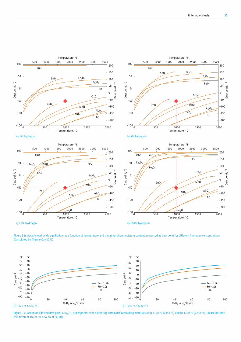
Sintering of steels 35
Figure 38: Metal/metal oxide equilibrium as a function of temperature and the atmosphere moisture content expressed as dew point for different hydrogen concentrations (Calculated by Thermo-Calc [37])
Figure 39: Maximum allowed dew point of N₂/H₂ atmospheres when sintering chromium-containing materials at a) 1120 °C (2050 °F) and b) 1250 °C (2280 °F). Please observe the different scales for dew point [4, 20]
–150
–100
–50
0
50
100
0 500 1000 1500 2000
–200
–150
–100
–50
0
50
100
150
200500 1000 1500 2000 2500 3000 3500
Dew
poi
nt, °
C
Dew
poi
nt, °
F
Temperature, °C
Temperature, °F
–150
–100
–50
0
50
100
0 500 1000 1500 2000
–200
–150
–100
–50
0
50
100
150
200500 1000 1500 2000 2500 3000 3500
Dew
poi
nt, °
C
Dew
poi
nt, °
F
Temperature, °C
Temperature, °F
–150
–100
–50
0
50
100
0 500 1000 1500 2000
–200
–150
–100
–50
0
50
100
150
200500 1000 1500 2000 2500 3000 3500
Dew
poi
nt, °
C
Dew
poi
nt, °
F
Temperature, °C
Temperature, °F
–150
–100
–50
0
50
100
0 500 1000 1500 2000
–200
–150
–100
–50
0
50
100
150
200500 1000 1500 2000 2500 3000 3500
Dew
poi
nt, °
C
Dew
poi
nt, °
F
Temperature, °C
Temperature, °F
CuO
SnO
TiO
MnOZnO
Fe2O3
Al2O3
SiO2
Cr2O3
Fe3O4
FeO
CuO
SnO
TiO
MnO
MgO
ZnO
Fe2O3
Al2O3SiO2
Cr2O3
Fe3O4
FeO
CuO SnO
TiO
MnO
MgO
ZnO
Fe2O3
Al2O3SiO2
Cr2O3
Fe3O4
FeO
CuOSnO
TiO
MnOZnO
Fe2O3
Al2O3
SiO2
Cr2O3
Fe3O4
FeO
a) 1% hydrogen b) 5% hydrogen
c) 25% hydrogen d) 100% hydrogen
–70–60–50–40–30–20–10
01020
–90–70–50–30–1010305070
0 20 40 60 80 100
Dew
poi
nt
°F °C
% H2 in N2/H2 mix
Fe – 1.5CrFe – 3Cr316L
a) 1120 °C (2050 °F)
–50–40–30–20–10
0102030
–60
–40
–20
0
20
40
60
80
0 20 40 60 80 100
Dew
poi
nt
°F °C
% H2 in N2/H2 mix
Fe – 1.5CrFe – 3Cr316L
b) 1250 °C (2280 °F)
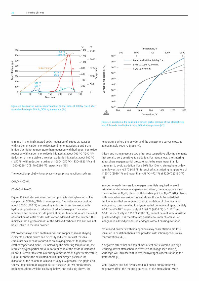
Sintering of steels36
0.15% C in the final sintered body. Reduction of oxides via reaction with carbon or carbon monoxide according to Reactions 2 and 3 are initiated at higher temperature than reduction with hydrogen. Iron oxide reduction with carbon monoxide is initiated at about 700 °C (1290 °F). Reduction of more stable chromium oxides is initiated at about 900 °C (1650 °F) with reduction maxima at 1000–1050 °C (1830–1920 °F) and 1200–1250 °C (2190–2280 °F) respectively [45].
The reduction probably takes place via gas phase reactions such as:
C+H₂O→CO+H₂
CO+FeO→Fe+CO₂
Figure 40 illustrates oxidation reaction products during heating of PM compactsin90%N₂/10%H₂atmosphere.Thewatervapourpeakatabout 370 °C (700 °F) is caused by reduction of surface oxide with hydrogen, possibly also reduction of adhered oxygen. The carbon monoxide and carbon dioxide peaks at higher temperature are the result of reduction of metal oxides with carbon admixed into the powder. This indicates that a given amount of the admixed carbon is lost and will not be dissolved in the iron powder.
PM powder alloys often contain nickel and copper as major alloying elements as their oxides can be easily reduced. For cost reasons, chromium has been introduced as an alloying element to replace the costlier copper and nickel. By increasing the sintering temperature, the required oxygen partial pressure for reduction of the oxide is increased. Hence it is easier to create a reducing atmosphere at higher temperature. Figure 41 shows the calculated equilibrium oxygen pressure for oxidation of the chromium-alloyed Astaloy CrM powder. The graph also shows the equilibrium oxygen partial pressure for two atmospheres. Both atmospheres will be oxidising below, and reducing above, the
temperature where the powder and the atmosphere curves cross, at approximately 1000 °C (1830 °F).
Silicon and manganese are two other cost competitive alloying elements that are also very sensitive to oxidation. For manganese, the sintering atmosphere oxygen partial pressure has to be even lower than for chromiumtoavoidoxidation.Fora90%N₂/10%H₂atmosphere,adewpoint lower than –63 °C (–81 °F) is required at a sintering temperature of 1120 °C (2050 °F) and lower than –58 °C (–72 °F) at 1200°C (2190 °F) [48].
In order to reach the very low oxygen potentials required to avoid oxidation of chromium, manganese and silicon, the atmosphere must consisteitherofN₂/H₂blendswithlowdewpointorN₂/CO/(H₂)blendswith low carbon monoxide concentrations. It should be noted that the low ratios that are required to avoid oxidation of chromium and manganese, corresponding to oxygen partial pressures of approximately 5•10–18and5•10–22respectivelyat1120°C(2050°F)or1•10–15 and 2•10–19 respectively at 1250 °C (2280 °F), cannot be met with industrial quality endogas. It is therefore not possible to sinter chromium- or manganese-alloyed powders in endogas without causing oxidation.
Pre-alloyed powders with homogenous alloy concentration are less sensitive to oxidation than mixed powders with inhomogenous alloy concentrations [49].
A negative effect that can sometimes affect parts sintered in a high reducing power atmosphere is excessive shrinkage (see Table 6). Shrinkage will increase with increased hydrogen concentration in the atmosphere [4].
Metal powder that has been stored in a humid atmosphere will negatively affect the reducing potential of the atmosphere. More
00
100
200
300
400
500
600
700
800
50 100 150 200 250 3000
370 °C698 °F
1030 °C1886 °F
1230 °C2246 °F
H2OCO2
COTemperature
Conc
entra
tion,
ppm
Tem
pera
ture
Time, min.
°C °F
200
400
600
800
1000
1200
1400 2500
2000
1500
1000
500
0
500 1000 1500 2000 2500
20010-39
Temperature, °C
Oxyg
en p
artia
l pre
ssur
e, P
O 2
Temperature, °F
Reduction limit for Astaloy CrM
2.5% CO, 7.5% H2, 90% N2
2.5% CO, 97.5% N2
10-36
10-33
10-30
10-27
10-24
10-21
10-18
10-15
10-12
400 600 800 1000 1200 1400
Figure 40: Gas analysis in oxide reduction trials on specimens of Astaloy CrM+0.5% C upon slow heating in 90% N₂/10% H₂ atmosphere [46]
Figure 41: Variation of the equilibrium oxygen partial pressure of two atmospheres and of the reduction limit of Astaloy CrM with temperature [47]
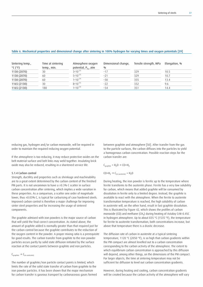
Sintering of steels 37
reducing gas, hydrogen and/or carbon monoxide, will be required in order to maintain the required reducing oxygen potential.
If the atmosphere is too reducing, it may reduce protective oxides on the belt material surface and belt links may weld together. Insulating brick oxide may also be reduced, resulting in a shortened service life.
5.1.4 Carbon controlStrength, ductility and properties such as shrinkage and machinability are to a great extent determined by the carbon content of the finished PM parts. It is not uncommon to have a ±0.3% C scatter in surface carbon concentration after sintering, which implies a wide variation in these properties. As a comparison, a scatter one order of magnitude lower, thus ±0.03% C, is typical for carburising of case hardened steels. Improved carbon control is therefore a major challenge for improving sinter steel properties and for increasing the usage of sintered components.
The graphite admixed with iron powders is the major source of carbon that will yield the final correct concentration. As stated above, the amount of graphite added is normally greater than that required just for the carbon control because the graphite contributes to the reduction of the oxygen content in the powder. A proper mixing ratio is a prerequisite for good results. The carbon transfer from graphite to the iron powder particles occurs partly by solid state diffusion initiated by the surface reaction at the contact points between graphite and iron particles.
Cgraphite→C(in austenite)
The number of graphite/iron particle contact points is limited, which limits the rate of the solid state transfer of carbon from graphite to the iron powder particles. It has been shown that the major mechanism for carbon transfer is gaseous transport by carbonaceous gases formed
between graphite and atmosphere [50]. After transfer from the gas to the particle surfaces, the carbon diffuses into the particles to yield a homogenous carbon concentration. Possible reaction steps for the carbon transfer are:
Cgraphite+H₂O→CO+H₂
CO+H₂→C(in austenite)+H₂O
During heating, the iron powder is ferritic up to the temperature where ferrite transforms to the austenite phase. Ferrite has a very low solubility for carbon, which means that added graphite will be consumed by dissolution in ferrite only to a limited degree. Instead, the graphite is available to react with the atmosphere. When the ferrite to austenite transformation temperature is reached, the high solubility of carbon in austenite will, on the other hand, result in fast graphite dissolution. This is illustrated by Figure 42, which shows the profiles of carbon monoxide(CO)andmethane(CH₄)duringheatingofAstaloyCrM-0.45Cin hydrogen atmosphere. Up to about 835 °C (1535 °F), the temperature for ferrite to austenite transformation, both concentrations increase, but above that temperature there is a drastic decrease.
The diffusion rate of carbon in austenite at a typical sintering temperature, 1120 °C (2050 °F), is so high that carbon gradients within the PM compact are almost levelled out to a carbon concentration corresponding to the carbon activity of the atmosphere. The extent to which equilibrium carbon concentration is approached by this diffusion will depend, among other things, on the dimensions of the PM compact. For larger objects, the time at sintering temperature may not be sufficient for diffusion to level out carbon concentration gradients.
However, during heating and cooling, carbon concentration gradients will be created because the carbon activity of the atmosphere will vary
Table 6. Mechanical properties and dimensional change after sintering in 100% hydrogen for varying times and oxygen potentials [39]
Sintering temp., °C (°F)1130 (2070)1130 (2070)1130 (2070)1165 (2130)1165 (2130)
Time at sintering temp., min.30606030180
Atmosphere oxygen potential, PO₂, atm3•10–25
5•10–25
1•10–24
8•10–25
1•10–24
Dimensional change, %–17–21–30–22–34
Tensile strength, MPa
329329355332351
Elongation, %
10.510.713.49.614.4

Sintering of steels38
with temperature and the diffusion rate for carbon will not be high enough to level out concentration gradients at lower temperatures. Therefore, it is not surprising that, in a statistical modelling test, the cooling rate was found to be one of the two most important parameters affecting carbon concentration when sintering in a nitrogen/hydrogen atmosphere (Figure 43). The second most important parameter was found to be the atmosphere dew point.
The general principles for atmosphere carbon control are based on the assumption of equilibrium between the gas phase and the sinter steel body. These principles are covered in other Linde Gas Expert Editions [18, 26], but a short summary is given below.
There are three possible carburising/decarburising equilibrium reactions:
CH₄←→C+2H₂ I
2CO←→C+CO₂ II
CO+H₂←→C+H₂O III
The fastest carburising reaction has been determined to be the forward reaction of equilibrium III and the fastest decarburising reaction to be the backward reaction of equilibrium III. The atmosphere carbon activity, aC, can be calculated from the equilibrium constant for reaction III in the same way as was used for calculating oxygen partial pressure from the equilibrium constant for oxidation. Thus:
aC=KIII × (PCO × PH₂
PH₂O)
Accordingly, the atmosphere carbon activity can be determined by analysing the atmospheric concentrations of carbon monoxide, hydrogen and water. However, in practice, the atmosphere carbon activity is best controlled with an oxygen probe or with carbon dioxide infrared gas analysis. This is based on the assumption of equilibrium in the water gas reaction:
CO+H₂=CO₂+H₂
and on the assumption that carbon control can be carried out as if equilibrium also exists for the carburising reaction:
2CO=C+CO₂ II
with the equilibrium constant:
KII=aC × PCO₂/P²CO
and the reaction:
CO=C+½O₂ IV
with the equilibrium constant:
KIV=ac × PO₂1/2/PCO
It is therefore possible to calculate the atmosphere carbon activity from theatmosphericconcentrationsofthecoupledspeciesCO+CO₂,CO+H₂+H₂OorCO+O₂.Thiscorrespondstowell-knownatmospherecontrolsystems using carbon dioxide, dew point or oxygen probe analysis.
00
50
100
150
200
250
300
1 2 3 4 5 6 7 8 9 10 11 12 13 14 15
Conc
entra
tion,
ppm
& te
mp.
, °C/
5
Time, h
Cr2O3 + 3C → 3CO + 2Cr
2H2 + C → CH4
Ferrite → Austenite
Austenite→ Ferrite
(FeCr2)O4+ C → CO + Fe + Cr2O3
Fe2O3+ 3H2 → 3H2O + 2Fe
Desorption of H2O
H2OT/5 °CCOCO2
CH4
Surfa
ce ca
rbon
conc
entra
tion,
wt%
C
Atmosphere dew point, °C (°F)
Cooling rate, Log(dT/dt), °C/s
0.60
0.55
0.50
0.45
0.40
0.35–35(–31)
–30(–22)–25(–13)
–20(–4)–15(5)
–0.4–0.2
00.2
0.4
Figure 42: Gas analysis profiles during heating of Astaloy CrM-0.45C in hydrogen atmosphere. The heating rate was 2 °C/min (3.6 °F/min) up to 1300 °C (2370 °F). The time at 1300°C (2370°F) was 10 minutes [42].
Figure 43: Surface carbon content as a function of the atmosphere dew point and the cooling rate from the sintering temperature. Sintering was carried out at 1120 °C (2050 °F) for 30 minutes in an N₂/H₂ atmosphere with addition of 0.5% methane [51].
Figure 44: Relationship between carbon activity and carbon potential (=carbon content in pure iron) as functions of temperature
0
0.1
0 0.2 0.4 0.6 0.8 1.0 1.2 1.4 1.6
0.2
0.3
0.4
0.5
0.6
0.7
0.8
0.9
1.0
1.1
1.2
aC ≥ 1 –> Soot
800 °C(1470 °F
900 °C(1650 °F
Carbon potential, wt% C
Carb
on a
ctiv
ity, a
C 1000 °C(1830 °F)
CP –> Soot

Sintering of steels 39
The value of the equilibrium constant is, as for oxidation/reduction, a function of the temperature [25].
Industrial heat treaters prefer to use the term “carbon potential” to signify the atmosphere carbon concentration instead of carbon activity. The atmosphere carbon potential is defined as the carbon concentration, expressed in weight percent, that a pure iron foil will have after being equilibrated with the atmosphere. A graphical presentation of the relationship between carbon activity and carbon potential is shown in Figure 44 [17].
By using the expressions for the equilibrium constants combined with the expressions for carbon potential, it is possible to determine the carbon potential for any carbon monoxide/hydrogen atmosphere with knowledge of the temperature and the concentrations of carbon monoxide, hydrogen and carbon dioxide, dew point, or a millivolt output from an oxygen probe. Figure 45 is an illustration of the relationship between carbon potential and carbon dioxide concentration or millivolt signal respectively. Note the great difference between atmospheres with 20% or 2% CO. At high temperature and low carbon monoxide concentration, the very low carbon dioxide values required
make the use of carbon dioxide analysis for carbon potential control inaccurate [17]. (A calculation tool for this type of analysis is available on the FERRONOVA® homepage [38].) For neutral conditions, i.e. neither decarburising nor carburising, the atmosphere carbon activity should be controlled to be equal to that given by the nominal carbon concentration in the surface of the PM part.
Thermochemically speaking, the atmosphere carbon potential is not equal to the carbon concentration of the steel PM compact unless it is a simple binary iron-carbon alloy. The carbon activity, however, is the same for the atmosphere and the steel at equilibrium. Therefore, the correct procedure when choosing a neutral atmosphere is to calculate the carbon activity of the steel first. That carbon activity and the corresponding carbon potential should then be adjusted to be the same for the atmosphere. For low alloy steels, simplified formulas can be used to calculate the neutral atmosphere carbon potential, but for high alloy steels such as tool and high-speed steels, a more rigorous equilibrium calculation must be carried out. An example of such a calculation for Astaloy CrM+0.6% C is shown in Figure 46. It can be seen from the diagram that the carbon activity, aC, is lowered with increased temperature. The numerical value for aC is about equal to the carbon
Figure 45: Relationship between carbon potential, temperature and a9 the atmosphere CO₂ concentration or b) oxygen potential expressed as the mV reading from an oxygen probe. The values are valid for atmospheres with 20 and 2 vol% CO.
Carbon potential, % C Carbon potential, % C
Carbon potential, % C Carbon potential, % C
970 °C (1780 °F)
970 °C (1780 °F)
970 °C (1780 °F)
820 °C (1510 °F)
820 °C (1510 °F)
820 °C (1510 °F)
1120 °C (2050 °F)
1120 °C (2050 °F)
1120 °C (2050 °F)
mV
mV
Vol% CO2
Vol% CO2
2.5 • 10-2
2.0 • 10-2
1.5 • 10-2
1.0 • 10-2
5.0 • 10-3
0 1140
1190
1240
1290
1340
10350
0.2
0.4
0.6
0.8
1.0
1.2
1.4
1.6
1.8
2.0
1085
1135
1185
1235
0.2 0.4 0.6 0.8 1.0 1.20.3 0.5 0.7 0.9 1.1 1.3 0.2 0.4 0.6 0.8 1.0 1.20.3 0.5 0.7 0.9 1.1 1.3
0.2 0.4 0.6 0.8 1.0 1.20.3 0.5 0.7 0.9 1.1 1.3
20% CO
2% CO
a b
0.2 0.4 0.6 0.8 1.0 1.20.3 0.5 0.7 0.9 1.1 1.3
970 °C (1780 °F)
820 °C (1510 °F)
1120 °C (2050 °F)
a) b)
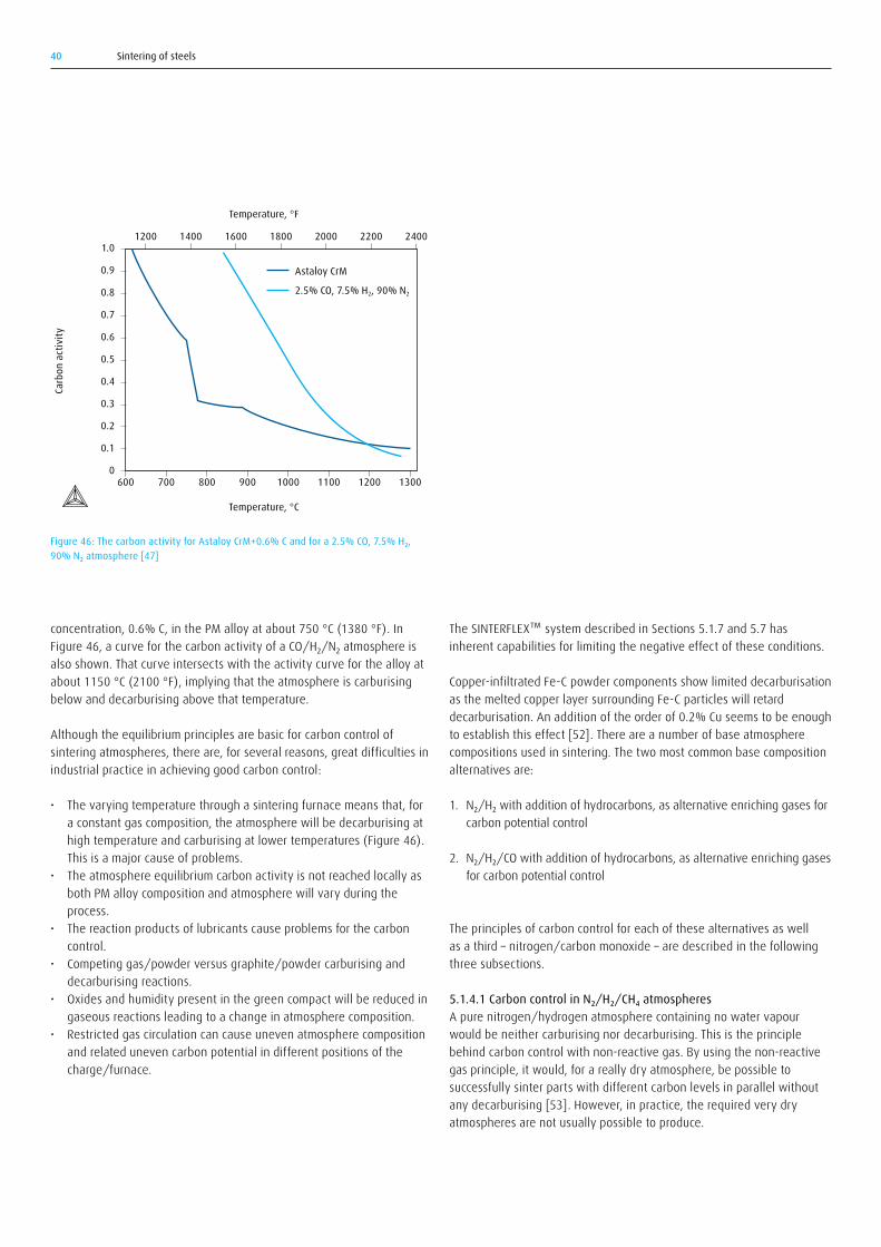
Sintering of steels40
The SINTERFLEX™ system described in Sections 5.1.7 and 5.7 has inherent capabilities for limiting the negative effect of these conditions.
Copper-infiltrated Fe-C powder components show limited decarburisation as the melted copper layer surrounding Fe-C particles will retard decarburisation. An addition of the order of 0.2% Cu seems to be enough to establish this effect [52]. There are a number of base atmosphere compositions used in sintering. The two most common base composition alternatives are:
1. N₂/H₂ with addition of hydrocarbons, as alternative enriching gases for carbon potential control
2. N₂/H₂/CO with addition of hydrocarbons, as alternative enriching gases for carbon potential control
The principles of carbon control for each of these alternatives as well as a third – nitrogen/carbon monoxide – are described in the following three subsections.
5.1.4.1 Carbon control in N₂/H₂/CH₄ atmospheresA pure nitrogen/hydrogen atmosphere containing no water vapour would be neither carburising nor decarburising. This is the principle behind carbon control with non-reactive gas. By using the non-reactive gas principle, it would, for a really dry atmosphere, be possible to successfully sinter parts with different carbon levels in parallel without any decarburising [53]. However, in practice, the required very dry atmospheres are not usually possible to produce.
concentration, 0.6% C, in the PM alloy at about 750 °C (1380 °F). In Figure46,acurveforthecarbonactivityofaCO/H₂/N₂atmosphereisalso shown. That curve intersects with the activity curve for the alloy at about 1150 °C (2100 °F), implying that the atmosphere is carburising below and decarburising above that temperature.
Although the equilibrium principles are basic for carbon control of sintering atmospheres, there are, for several reasons, great difficulties in industrial practice in achieving good carbon control:
• The varying temperature through a sintering furnace means that, for a constant gas composition, the atmosphere will be decarburising at high temperature and carburising at lower temperatures (Figure 46). This is a major cause of problems.
• The atmosphere equilibrium carbon activity is not reached locally as both PM alloy composition and atmosphere will vary during the process.
• The reaction products of lubricants cause problems for the carbon control.
• Competing gas/powder versus graphite/powder carburising and decarburising reactions.
• Oxides and humidity present in the green compact will be reduced in gaseous reactions leading to a change in atmosphere composition.
• Restricted gas circulation can cause uneven atmosphere composition and related uneven carbon potential in different positions of the charge/furnace.
600 800 1000 12007000
0.1
0.2
0.3
0.4
0.5
0.6
0.7
0.8
0.9
1.0
900
Temperature, °C
Temperature, °F
Carb
on a
ctiv
ity
1100 1300
1200 1400 1600 1800 2000 2200 2400
Astaloy CrM
2.5% CO, 7.5% H2, 90% N2
Figure 46: The carbon activity for Astaloy CrM+0.6% C and for a 2.5% CO, 7.5% H₂, 90% N₂ atmosphere [47]

Sintering of steels 41
As a result of reaction between hydrogen and oxygen – from air leakage or being present in the powder – there will always be some watervapour(H₂O)intheatmosphere.Insuchanatmosphere,bothcarburising, a, and decarburising reactions, b and c, are possible according to the following reactions:
CH₄→C+2H₂ a
H₂O+C→CO+H₂ b
2H₂+C→CH₄ c
If no water vapour is present, carburising will occur according to Reaction a and decarburising according to Reaction c. In the presence of water vapour, which is typically the case in practice, decarburising will occur by Reaction b as well. A steady state balance between carburising by Reaction a and decarburising by Reaction b will develop. This balance, written as aSS (corresponding to a certain carbon potential) in the illustration in Figure 47, is reached when the rate of carburising from Reaction a and the rate of decarburising from Reaction b are equal. Rate expressions for both carburising and decarburising as functions of atmosphere composition have been determined by Grabke [54]. From these expressions and connected quantitative values for reaction rates and equilibrium constants, it is possible to determine aSS by analysis of hydrogen, methane and carbon monoxide. This would not be a straight equilibrium-based control as explored in the preceding section, but a control based on kinetics. However, this approach has not been practically applied. One reason is that the rate of kinetic reactions involving methane is influenced by catalytic effects from the load and the furnace interior surfaces. Therefore, the reaction rates will vary in the load, which makes the use of kinetic data problematic to apply.
Williams [55] showed that aSSinaCH₄/H₂/H₂Omixtureat920°C(1690 °F) was almost independent of the water vapour concentrations for concentrations below 25 ppm (dew point < –50 °C, (< –58 °F)), but for higher concentrations, there was a drastic decrease in the value of aSS. Sintering tests at higher temperature have indicated that decarburising increases at parabolic rate with increased water vapour content (Figure 48). If the atmosphere dew point is lower than –30 °C (–22°F)(correspondingtoapproximately40ppmH₂O),thedecarburisingrate has been found to be negligible for a hydrogen concentration of 10% in the atmosphere.
If the water vapour concentration exceeds a certain value determined from practical experience, methane can be added to increase the steady state carbon potential to the required level. Practical experience is that additions of methane should be limited to a few percent because excessive methane additions will create soot on parts and on the furnace interior according to the reaction:
CH₄→C(soot)+2H₂
Increased hydrogen concentration in the atmosphere will lead to water vapour formation from reduction of metal oxides (1) and reaction with oxygen (2):
1)H₂+MeO→H₂O+Me
2)H₂+½O₂→H₂O
Rate
of c
arbo
n tra
nsfe
r, v
CH4 = Cin austenite + 2H2
Cin austenite + H2O CO + H2
Surface carbon activity, aC
v1 = k1 PH23/2 (aC
eq1 – aCSS)
v2 = –kS aC PH2O/PH2
aCeq1aC
SS
0.00
0.20
0.40
0.60
0.80
1.00
1.20
0 500 1000 1500 2000 2500 3000 3500 4000 4500 5000
Deca
rbur
ised
dept
h, m
m
Water vapour conc., ppm
–20 °C(–4 °F)
–12 °C(10 °F)
–4 °C(25 °F)
–28 °C(–18 °F)
Figure 47: Carburising and decarburising reactions in a H₂/CH₄/H₂O atmosphere as a function of the surface carbon activity of the exposed steel
Figure 48: Relationship between the atmosphere water vapour concentration (dew points indicated) and the thickness of decarburised layer. Sintering atmosphere 90% N₂/10% H₂ [56]

Sintering of steels42
Figure 50 that 0.4% C at 900 °C (1650 °F) – a temperature where the carburising rate is still so high that a close-to-equilibrium carbon concentration would be expected – corresponds to a carbon potential close to zero at the sintering temperature. If the atmosphere carbon potential is controlled to 0.4% C at 900 °C (1650 °F), decarburising would then occur at the sintering temperature. This, of course, is one reason for the difficulty of carbon potential control during sintering.
With increased amounts of carbon monoxide and hydrogen, there is a kinetic effect on the carburising as well as on the decarburising reaction. Theoretically, the carbon transfer expressed as mass transfer per time unit (dm/dt) from the atmosphere to the iron powder surface is proportional not only to the difference between the atmosphere carbon potential and the surface carbon concentration, (ccg – ccs), but also to a kinetic factor k’. This is expressed by the following equation:
dm/dt=k’•(ccg – ccs)
The kinetic factor k’ is about proportional to the product of carbon monoxide and hydrogen concentrations. The carburising rate will therefore decrease with reduced amounts of carbon monoxide and hydrogen. This as well as the temperature effect is illustrated in Figure 51. All carbon concentration gradients in the graphic are calculated for the same carbon potential, but for atmospheres with different amounts ofCO+H₂.Ascanbeseen,thereisalargecarburisingeffectinendogas,butamorelimitedoneina5%CO/10%H₂blendandalmostnoneinthe2%CO/0.1%H₂blend.Awaytolimitthenegativeeffectofthevarying carbon potential shown in Figure 50 is therefore to keep carbon monoxide and hydrogen concentrations low.
Also the decarburising rate increases with an increased amount of carbon monoxide and hydrogen or more specifically with the amount of water vapour in the atmosphere. (For a constant carbon potential, the
The water vapour produced in these reactions will cause decarburisation. A guideline determined by experiment is that the use of less than 5% H₂intheatmospherelimitsbothcarburisinganddecarburisingrates[56–57] (see Figure 49). Keeping the decarburisation very low by the use of low hydrogen concentrations in the atmosphere will have the disadvantage that the oxide reduction power and the atmosphere buffer capacity will be reduced and consequently the sintered part properties may be compromised.
InahumidN₂/H₂/CH₄atmosphere,carbonmonoxidewillbeformedfromthe reaction between methane and water according to the reaction:
CH₄+H₂O→CO+3H₂
Therefore, it is theoretically possible to base the carbon potential control upon analysis of carbon monoxide and oxygen partial pressures. This has proved to be possible in practice with the use of natural gas as the enriching gas for carbon potential control [49].
5.1.4.2 Carbon control in N₂/CO/H₂ atmospheresThecarbonpotentialprofilealongasinteringfurnacewithaCO/H₂atmosphere will vary due to the strong temperature effect on the carbon potential at fixed atmosphere composition. Figure 50 shows the carbon potential at equilibrium conditions for atmospheres with the same CO/H₂ratiowithfourdifferentcarbonpotentialscorrespondingtofourdewpoints, carbon dioxide concentrations or mV readings. The variation in carbonpotentialisthesameforfixedCO/H₂ratiosirrespectiveoftheabsolute values of carbon monoxide and hydrogen. For example, 25% CO/50%H₂willgivethesameratioas0.5%CO/1%H₂.Thedatashowshow an atmosphere with a low carbon potential at sintering temperature – even as low as 0.05% C – will give as high a carbon potential, over 1.5% C, at 900 °C (1650 °F). If, for example, 0.4% C is required in the final compact (assuming pure iron and carbon) it can be seen from
0.00
0.05
0.10
0.15
0.20
0.25
0.30
0.35
0 5 10 15 20 25 30 35
Deca
rbur
ised
dept
h, m
m
Vol% H2 in N2
1400
1200
1000
800
600
400
200
0
2500
2000
1500
1000
500
0
°C °F
Temperature
Temperature
0.400.20
0.100.05
Distance from furnace inlet, arbitrary unitCa
rbon
pot
entia
l, %
C0
0.50
1.00
1.50
2.00
2.50
Figure 49: Surface decarburisation as a function of the atmosphere hydrogen content [57]
Figure 50: Carbon potential as a function of temperature for CO/H₂ atmospheres with ratio CO/H₂ = 1/2. Four carbon potentials with values 0.4, 0.2, 0.1 and 0.05% C at the highest temperature were selected as the base for the calculation.
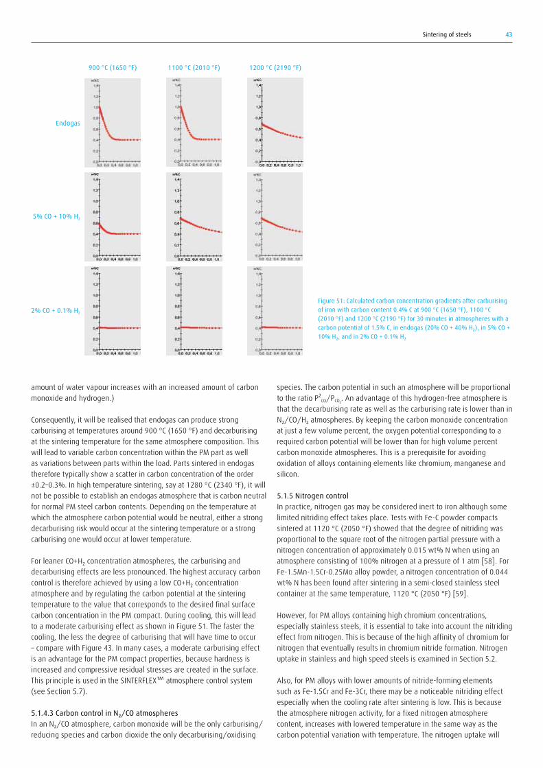
Sintering of steels 43
amount of water vapour increases with an increased amount of carbon monoxide and hydrogen.)
Consequently, it will be realised that endogas can produce strong carburising at temperatures around 900 °C (1650 °F) and decarburising at the sintering temperature for the same atmosphere composition. This will lead to variable carbon concentration within the PM part as well as variations between parts within the load. Parts sintered in endogas therefore typically show a scatter in carbon concentration of the order ±0.2–0.3%. In high temperature sintering, say at 1280 °C (2340 °F), it will not be possible to establish an endogas atmosphere that is carbon neutral for normal PM steel carbon contents. Depending on the temperature at which the atmosphere carbon potential would be neutral, either a strong decarburising risk would occur at the sintering temperature or a strong carburising one would occur at lower temperature.
ForleanerCO+H₂concentrationatmospheres,thecarburisinganddecarburising effects are less pronounced. The highest accuracy carbon controlisthereforeachievedbyusingalowCO+H₂concentrationatmosphere and by regulating the carbon potential at the sintering temperature to the value that corresponds to the desired final surface carbon concentration in the PM compact. During cooling, this will lead to a moderate carburising effect as shown in Figure 51. The faster the cooling, the less the degree of carburising that will have time to occur – compare with Figure 43. In many cases, a moderate carburising effect is an advantage for the PM compact properties, because hardness is increased and compressive residual stresses are created in the surface. This principle is used in the SINTERFLEX™ atmosphere control system (see Section 5.7).
5.1.4.3 Carbon control in N₂/CO atmospheresInanN₂/COatmosphere,carbonmonoxidewillbetheonlycarburising/reducing species and carbon dioxide the only decarburising/oxidising
species. The carbon potential in such an atmosphere will be proportional to the ratio P²CO/PCO₂. An advantage of this hydrogen-free atmosphere is that the decarburising rate as well as the carburising rate is lower than in N₂/CO/H₂atmospheres.Bykeepingthecarbonmonoxideconcentrationat just a few volume percent, the oxygen potential corresponding to a required carbon potential will be lower than for high volume percent carbon monoxide atmospheres. This is a prerequisite for avoiding oxidation of alloys containing elements like chromium, manganese and silicon.
5.1.5 Nitrogen controlIn practice, nitrogen gas may be considered inert to iron although some limited nitriding effect takes place. Tests with Fe-C powder compacts sintered at 1120 °C (2050 °F) showed that the degree of nitriding was proportional to the square root of the nitrogen partial pressure with a nitrogen concentration of approximately 0.015 wt% N when using an atmosphere consisting of 100% nitrogen at a pressure of 1 atm [58]. For Fe-1.5Mn-1.5Cr-0.25Mo alloy powder, a nitrogen concentration of 0.044 wt% N has been found after sintering in a semi-closed stainless steel container at the same temperature, 1120 °C (2050 °F) [59].
However, for PM alloys containing high chromium concentrations, especially stainless steels, it is essential to take into account the nitriding effect from nitrogen. This is because of the high affinity of chromium for nitrogen that eventually results in chromium nitride formation. Nitrogen uptake in stainless and high speed steels is examined in Section 5.2.
Also, for PM alloys with lower amounts of nitride-forming elements such as Fe-1.5Cr and Fe-3Cr, there may be a noticeable nitriding effect especially when the cooling rate after sintering is low. This is because the atmosphere nitrogen activity, for a fixed nitrogen atmosphere content, increases with lowered temperature in the same way as the carbon potential variation with temperature. The nitrogen uptake will
Figure 51: Calculated carbon concentration gradients after carburising of iron with carbon content 0.4% C at 900 °C (1650 °F), 1100 °C (2010 °F) and 1200 °C (2190 °F) for 30 minutes in atmospheres with a carbon potential of 1.5% C, in endogas (20% CO + 40% H₂), in 5% CO + 10% H₂, and in 2% CO + 0.1% H₂
Endogas
900 °C (1650 °F) 1100 °C (2010 °F) 1200 °C (2190 °F)
5% CO + 10% H2
2% CO + 0.1% H2
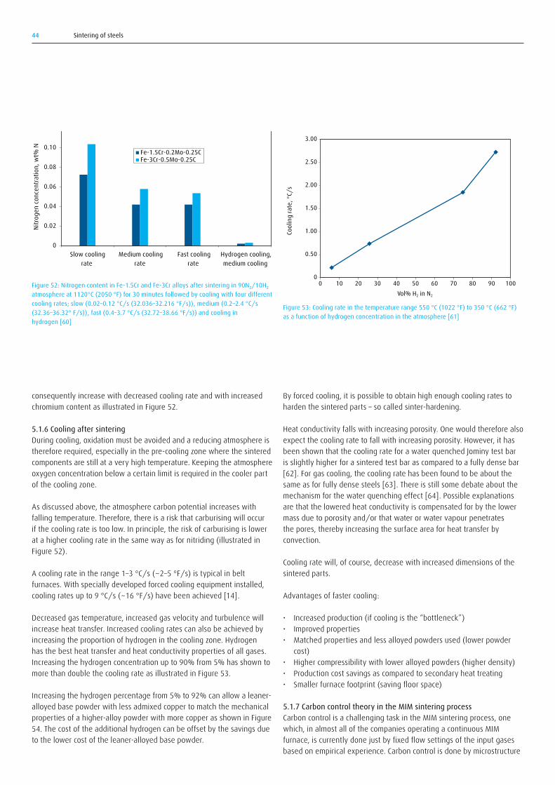
Sintering of steels44
By forced cooling, it is possible to obtain high enough cooling rates to harden the sintered parts – so called sinter-hardening.
Heat conductivity falls with increasing porosity. One would therefore also expect the cooling rate to fall with increasing porosity. However, it has been shown that the cooling rate for a water quenched Jominy test bar is slightly higher for a sintered test bar as compared to a fully dense bar [62]. For gas cooling, the cooling rate has been found to be about the same as for fully dense steels [63]. There is still some debate about the mechanism for the water quenching effect [64]. Possible explanations are that the lowered heat conductivity is compensated for by the lower mass due to porosity and/or that water or water vapour penetrates the pores, thereby increasing the surface area for heat transfer by convection.
Cooling rate will, of course, decrease with increased dimensions of the sintered parts.
Advantages of faster cooling:
• Increased production (if cooling is the “bottleneck”)• Improved properties• Matched properties and less alloyed powders used (lower powder
cost)• Higher compressibility with lower alloyed powders (higher density)• Production cost savings as compared to secondary heat treating• Smaller furnace footprint (saving floor space)
5.1.7 Carbon control theory in the MIM sintering process Carbon control is a challenging task in the MIM sintering process, one which, in almost all of the companies operating a continuous MIM furnace, is currently done just by fixed flow settings of the input gases based on empirical experience. Carbon control is done by microstructure
consequently increase with decreased cooling rate and with increased chromium content as illustrated in Figure 52.
5.1.6 Cooling after sinteringDuring cooling, oxidation must be avoided and a reducing atmosphere is therefore required, especially in the pre-cooling zone where the sintered components are still at a very high temperature. Keeping the atmosphere oxygen concentration below a certain limit is required in the cooler part of the cooling zone.
As discussed above, the atmosphere carbon potential increases with falling temperature. Therefore, there is a risk that carburising will occur if the cooling rate is too low. In principle, the risk of carburising is lower at a higher cooling rate in the same way as for nitriding (illustrated in Figure 52).
A cooling rate in the range 1–3 °C/s (~2–5 °F/s) is typical in belt furnaces. With specially developed forced cooling equipment installed, cooling rates up to 9 °C/s (~16 °F/s) have been achieved [14].
Decreased gas temperature, increased gas velocity and turbulence will increase heat transfer. Increased cooling rates can also be achieved by increasing the proportion of hydrogen in the cooling zone. Hydrogen has the best heat transfer and heat conductivity properties of all gases. Increasing the hydrogen concentration up to 90% from 5% has shown to more than double the cooling rate as illustrated in Figure 53.
Increasing the hydrogen percentage from 5% to 92% can allow a leaner-alloyed base powder with less admixed copper to match the mechanical properties of a higher-alloy powder with more copper as shown in Figure 54. The cost of the additional hydrogen can be offset by the savings due to the lower cost of the leaner-alloyed base powder.
0
0.02
0.04
0.06
0.08
0.10
0.12
Slow coolingrate
Medium coolingrate
Fast coolingrate
Hydrogen cooling,medium cooling
rate
Nitro
gen
conc
entra
tion,
wt%
N
Fe-1.5Cr-0.2Mo-0.25C Fe-3Cr-0.5Mo-0.25C
Figure 52: Nitrogen content in Fe-1.5Cr and Fe-3Cr alloys after sintering in 90N₂/10H₂ atmosphere at 1120°C (2050 °F) for 30 minutes followed by cooling with four different cooling rates; slow (0.02–0.12 °C/s (32.036–32.216 °F/s)), medium (0.2–2.4 °C/s (32.36–36.32° F/s)), fast (0.4–3.7 °C/s (32.72–38.66 °F/s)) and cooling in hydrogen [60]
Figure 53: Cooling rate in the temperature range 550 °C (1022 °F) to 350 °C (662 °F) as a function of hydrogen concentration in the atmosphere [61]
0
0.50
1.00
1.50
2.00
2.50
3.00
0 10 20 30 40 50 60 70 80 90 100Co
olin
g ra
te, °
C/s
Vol% H2 in N2

Sintering of steels 45
and or bulk component destructive carbon tests on ready-sintered parts, which means that unacceptable results cannot be corrected; the parts either pass the requirements or are rejected, leading to high scrap rates. A 20 to 25% scrap rate at a typical MIM shop is not uncommon.
Figure 55 shows a graph demonstrating the current practice in “green” versus an operation handled by the SINTERFLEX™ total carbon control system in “red”.
a. Existing practice: Predictive decarburisation A SEM analysis was done on a BASF CATAMOLD FN02 material after catalytic de-binding (brown parts). It was found that in many of the
locations, the carbon content was well over the 3% carbon content range. Figure 56 and Table 7 below show the analysing points and their content of carbon under SEM analysis. Another destructive bulk part carbon analysis was done on a bulk brown part where the carbon content was found to be approximately 4.8 percent.
Figure 54: Apparent hardness as a function of the atmosphere hydrogen concentration and amount of admixed copper in the base powder [61]
44
49
54
59
64
69
0 0.5 1.0 1.5 2.0
Har
dnes
s, H
RA
Copper content, wt%
5% H2
22% H2
70% H2
92% H2
Figure 55: Comparison of current practice versus SINTERFLEX™ carbon control in MIM sintering process
Conventional sintering methods are based on prediction of final C content loss and vary dependent on the de-binding performance at the time of production – therefore variations may or may not occur
SINTERFLEX controlled de-binding system removes the excess carbon coming from the binder
SINTERFLEX maintains the carbon in the base powder by providing a neutral atmosphereSINTERFLEX C potential
SINTERFLEX reduces C content variation in final sintered batches
thermal de-binding zone high heat zone cooling zone
furnace length
C co
nten
t/br
own
4.8% C content
0.65% C content
0.05% C content

Sintering of steels46
b. A new concept: Total atmosphere control with SINTERFLEX™ in MIM sinteringThe SINTERFLEX™ system, however, does not rely on the availability of the binders (hydrocarbon) as the source of carbon in the high heat zone. The sintering in the Press and Sinter process requires the lubricant to be removed before the high heat zone is entered and the same principle applies for the MIM sintering process. The SINTERFLEX™ system starts with completely removing the binders in the preheat (de-binding) zone of the furnace (as shown in the red line). The system creates a very decarburising atmosphere to make sure the binder is removed in this zone. Therefore, the brown body no longer contains any binders when entering the high heat sintering zone. The second process step section using the SINTERFLEX™ system starts to create a neutral atmosphere as in most of the industrial hardening furnaces, regardless of the final part requirement, to make sure the carbon in the matrix left after de-binding is protected in a neutral atmosphere. The parts then enter the cooling zone where there is still a slight carbon-containing atmosphere present. This will allow final protection of the carbon from the surface.
Therefore, the parts are expected to leave the furnace with the final carbon content requirement and within the specifications and with the lowest possible variation across parts.
5.2 Sintering atmospheres for stainless steel and high speed steelStainless steels are typically sintered at high temperature – up to 1250 °C (2280 °F). Sintering of stainless steel requires highly reducing atmospheres to avoid formation of chromium oxides. If sintering is performed at lower temperature, for example, 1140 °C (2084 °F), the atmosphere oxygen potential will – for typical hydrogen or hydrogen/nitrogen atmospheres – be too high for reduction of chromium oxides [65]. Even if the atmosphere is reducing with respect to chromium oxide at the sintering temperature, oxidation may occur during cooling if the
Table 7. Carbon content of spots
SpectrumSpectrum 1Spectrum 2Spectrum 3Spectrum 4Spectrum 5Spectrum 6Spectrum 7Spectrum 8Spectrum 9Spectrum 10
Max.Min.
C7.285.122.926.644.392.041.551.203.251.77
7.281.20
Fe74.4894.8896.2793.3695.6197.9698.4598.8096.7597.34
98.8074.48
Existing practice is illustrated in Figure 55 with the green line. The brown part starts with 4.8% carbon when entering the thermal de-binding zone where the binder is supposed to be removed from the MIM mass. However, the carbon will be carried to the high heat zone probably in the outer sections of the parts, causing a source for carbon in the atmosphere and hence providing protection for decarburising. However, the measurements show that the atmosphere is extremely decarburising also in the sintering, high-temperature zone. Therefore, the de-binding continues until the sintering finishes where the parts reach their final carbon results. Because of this uncontrolled decarburisation, it is with the existing practice always difficult to predict the final carbon concentration of sintered parts as well as the variation of the carbon concentration from one batch to other batch due to the unstable furnace atmosphere.
Figure 56: Analysing points under SEM of CATAMOLD FN02 material
Figure 57: Solubility of nitrogen in austenitic 8% Ni steel with varying chromium concentration. PN₂= nitrogen partial pressure (=volume % nitrogen/100) [67]
10-3
900Temperature, °C
Temperature, °F
Austenite + chromium nitride (Cr2N)
Nitro
gen
gas p
artia
l pre
ssur
e, P
N 2
950 1000 1050 1100 1150 1200
1700 1800 1900 2000 2100 2200
10-2
10-1
100
101
100 % nitrogen
Cracked ammonia
10 % nitrogen
Austenite
24 % Cr
18 % Cr
16 % Cr
Spectrum 11Spectrum 9
Spectrum 7
Spectrum 1
Spectrum 2
Spectrum 8Spectrum 5
Spectrum 4
Spectrum 3
Spectrum 10 Spectrum 6

Sintering of steels 47
cooling rate is too low. Oxidation will lead to lower corrosion resistance, strength and ductility.
The risk of forming nitrides also has to be considered. The atmosphere nitrogen activity that causes nitride formation decreases with decreased temperature. This is illustrated in Figure 57. For combinations of nitrogen activities and temperatures corresponding to points below the equilibrium lines, all nitrogen is dissolved in the face-centred cubic (FCC) austenite, whereas for points above the lines, close-packed hexagonal (HCP)chromiumnitride(Cr₂N)isformed.Themaximumnitrogensolubility in austenite decreases with decreasing temperature in a similar way to the oxygen potential for oxidation. This means that even if nitrogen pick-up is avoided during high temperature sintering, there is the risk of nitriding and chromium nitride formation during cooling. It has been found that a cooling rate in the range 200–450 °C/min (3–7.5 °C/s (5.4–13.5 °F/s)) is required to avoid chromium nitride formation during cooling when sintering is carried out in a cracked ammonia atmosphere at about 1250 °C (2280 °F) [66]. As can be seen in Figure 57, the tendency to form nitrides increases with increasing chromium content in the stainless steel.
Chromium has high affinity for carbon as well as nitrogen. Examples of the possible consequences are shown in Table 8. It tabulates the carbon concentration in stainless steel when sintering was carried out in a hydrogen atmosphere in a graphite furnace. In this case, hydrogen has reacted with the graphite to form methane that carburises the steel. An important conclusion of this study was that sintering in a graphite furnace under vacuum with argon as backfill gas – thus avoiding formation of methane – gave the same sintering result with regard to strength and ductility as sintering in a molybdenum furnace under a hydrogen atmosphere.
Table 8. Properties of type 316L stainless steel after sintering at 1350 °C (2460 °F) in various atmospheres
Furnace
Molybdenum
Graphite
Atmosphere
HydrogenArgonNitrogenArgonNitrogen95%N₂/5%H₂
Sinter density, g/cm³7.927.757.137.747.227.25
wt% N
0.0010.0020.3830.0020.3810.367
wt% O
0.0150.020.050.060.060.01
wt% C
0.00380.00370.00590.00610.00360.0864
Nitrogen and carbon pick-up are usually deleterious to both corrosion resistance and ductility, although strength is increased. Therefore, for high temperature sintering of stainless steels, pure hydrogen or argon/hydrogen blends are preferred both with respect to oxide reduction and avoidance of nitrides or carbides.
Nitrogen uptake also takes place during sintering of high speed steels (HSS) in nitrogen atmospheres, but, contrary to stainless steels, the nitriding effect is mostly positive. The effect of nitriding is an increased hardness that is beneficial in HSS applications. By the formation of fine carbonitrides, instead of coarser carbides, grain growth is retarded
[68-69]. The sintering temperature for HSS is normally about 1250 °C (2280 °F), close to the solidus temperature. However, it has been shown that sintering in a nitrogen/hydrogen atmosphere can yield good results at temperatures as low as 1135 °C (2075 °F) [68].
5.3 Sintering atmospheres for non-ferrous metalsThe proper sintering atmosphere selection for non-ferrous metals should be made with regard to 1) risk of oxidation, 2) risk of nitrogen or carbon pick-up (chromium, titanium and zirconium) and hydrogen pick-up (titanium). Table 9 gives some general guidelines for the proper choice.
Table 9. Typical atmospheres for sintering of non-ferrous alloys
Base alloy
Aluminium
Copper (brass, bronze)
Nickel
Titanium
Tungsten, molybdenumCemented carbides
Sintering temperature, °C (°F)600–620 °C (1110–1150 °F)850–900 °C (1560–1650 °F)
950–1000 °C (1740–1830 °F)1000–1260 °C (1830–2300 °F)1200–1430 °C (2190–2610 °F)1350–1460 °C (2460–2660 °F)
Atmosphere
100%N₂
N₂/5–10%H₂ N₂/5–20%endogas N₂/5–20%methanolN₂/5–10%H₂
Ar/H₂vacuum
100%H₂
100%H₂vacuum
Copper and nickel are fairly noble metals that oxidise at rather high oxygen potentials. Nitrogen/hydrogen atmospheres, with only a few percent of hydrogen, are therefore normally enough for avoiding oxidation. However, for alloys such as brass and bronzes that contain elements more prone to be oxidised, like zinc and tin, a much higher reducing power is required of the atmosphere, necessitating the use of hydrogen concentrations up to 100%.
Aluminium is one of the metals most sensitive to oxidation and, from a thermochemical equilibrium point of view, it would, in practice, be impossible to reach the very low oxygen potential required to avoid oxidation. Nevertheless, pure nitrogen is the preferred atmosphere for sintering of aluminium PM compacts and has given better results than vacuum, argon, nitrogen/hydrogen or argon/hydrogen atmospheres [70].
Titanium is very reactive both with regard to oxidation and nitrogen/carbon pick-up. Argon or argon/hydrogen atmospheres are therefore required.

Sintering of steels48
elements with lower vapour pressure such as tungsten and molybdenum. This effect has been observed to cause carbide enrichment at the surface after vacuum sintering of high speed steel [72]. For stainless steel vacuum sintering, the risk of vaporisation of chromium should be considered. The way to counteract vaporisation is to use a backfill pressure that is higher than the respective vapour pressures of these alloying elements. At high enough temperature and low enough pressure, oxide removal by dissociation is possible. However, reduction by reaction between the metal oxide and admixed carbon leading to carbon monoxide formation is the dominant oxide reduction mechanism during vacuum sintering. The carbon addition to the powder compact must therefore be adjusted to compensate for the loss of carbon in the oxide reduction process.
Sintering in vacuum has the advantage that settings of temperature-pressure-atmosphere can easily be adjusted to the different process steps (delubrication, sintering and cooling).
A typical delubrication/debinding-sintering cycle is shown in Figure 58. The parts are first heated to the lubricant/binder vaporisation temperature. The temperature is held at this level until outgassing
5.4 Sintering atmospheres for permanent magnetsPermanent magnets made by sintering of Nd-Fe-B powders have far better permanent magnetic properties than traditional magnets. These magnets are key functional materials in modern advanced applications such as hybrid vehicle motors, consumer electronics (e.g. mobile phones), medical appliances, military equipment, etc.
Sintering is carried out in argon atmospheres or in vacuum at temperatures up to 1160 °C (2120 °F).
5.5 Vacuum sinteringIn vacuum, there is not sufficient gas present to cause detrimental oxidation or other reactions. Surface residues on parts heated in vacuum will be removed by vaporising, and the vapours can be pumped out of the furnace.
Alloying elements will vaporise if the pressure is below the vapour pressures of the respective metal. Manganese, chromium and copper are examples of elements with fairly high vapour pressures that can lead to vaporisation [71]. For high speed steels, this can lead to depletion of these elements at the surface and concurrently an enrichment of
Time, h
TemperaturePressure
Wax removal
Sintering
Cool
ing
Polymer removal
Tem
pera
ture
Pres
sure
, tor
r
0
°F °C
0
100
300
500
700
900
1100
1300
0
400
800
1200
1600
2000
2400
2 4 6 8 10 12 14 16
10
1
10-1
10-2
10-3
10-4
102
103
Figure 58: Typical binder removal and sintering cycle in a vacuum furnace [74]

Sintering of steels 49
is complete. The partial gas pressure in this step is below that of the lubricant/binder vapour pressure, but above that of the other elements in the PM alloy. Vaporising of lubricants or binders occurs at sub-atmospheric pressure at a somewhat lower temperature and is more complete than debinding at atmospheric pressure [73].
In the second step, the temperature is increased up to the sintering temperature of the base alloy and held for a sufficiently long time to ensure that solid state diffusion and sintering occur. The furnace and parts are then cooled by gas cooling, possibly forced gas cooling for sinter-hardening.
One problem is the risk of contamination of the vacuum furnace by deposits from condensed lubricant vapours, especially during the debinding step. This can occur in the vacuum pumps and on furnace interior walls. To solve this problem during debinding, it is essential to keep the temperature of all furnace interior parts below the temperature at which vapours will crack or dissociate into solid, carbon-containing deposits. Furthermore, it is necessary to eliminate cold spots or walls in the furnace onto which vapours may condense to give solid or liquid deposits. A solution to these problems is the system shown in Figure 59
with pipelines out of the furnace having a sufficiently high temperature to keep binders in vapour form until they reach a point where controlled condensation can occur. The furnace shown in Figure 60 has two vacuum pumping lines. The first pumping line removes binders and carries them out through the bottom of the furnace. A water cooled trap in front of the vacuum booster collects residual lubricant/binder materials. A second vacuum pumping line is connected to the high vacuum diffusion pump that produces the high vacuum level required for the sintering processes.
Vacuum furnaces may also be used for overpressure sintering, which is primarily used for sintering of cemented carbides [75].
One possibility with vacuum sintering is to add a gaseous carbon source,primarilyacetylene(C₂H₂),thatwillgivethecorrectfinalcarbonconcentration in the sintered part instead of using admixed graphite for this purpose.
Figure 59: Vacuum furnace with equipment for controlled collection of vapour condensate [74]
Figure 60: Debinding and sintering furnaces with two bar argon cooling (courtesy of Ipsen)
Vapour lubricant
To vacuum pump
Condenser
Liquid lubricant
Condensation of vapour

Sintering of steels50
5.6 Atmosphere analysis
Atmosphere analysis is the basis for atmosphere control, often just as a check for supervision, but, in the advanced cases, as the basis of online closed-loop atmosphere control. Atmosphere analysis is also an important method of establishing furnace data as well as a method of solving possible problems. Figure 61 shows a gas sampling set-up that will give analysis results from the different zones in the furnace. The gas sampling system should have the following features:
• A nitrogen supply for back purging to clean sample lines• A gas sample pump, filters and sample gas flow control to ensure a
consistent gas sample stream• Switching valves to enable sampling from different points in the
furnace• Sample tubes located away from gas inlets and close to parts in order
to give representative results
Back purging and ample filters reduce the risk of forming vapour condensates that clog the sample lines and diminish analysis accuracy. In order to avoid any contamination of the sintering zone atmosphere from lubricant vapours in the preheat zone, it is an advantage to analyse the atmosphere at a point approximately 90% into the length of the preheat zone. The clogging problem makes online continuous gas analysis rare in sintering furnaces. Checks at regular intervals can replace that and avoid the problem.
Entry zone Preheat zone
Sintering zone
Cooling zone
Sample boxN2 purge
IR analyser
H2 analyser
Dew point analyser
O2 analyser
Figure 62: Analysis cart incorporating units for computerised data handling (upper part), sample gas handling with pump and valves, and gas analysers for hydrogen, methane, carbon monoxide and carbon dioxide (lower part)
Figure 61: Schematic diagram for an atmosphere sampling system

Sintering of steels 51
oxygen probe able to operate at up to 1150 °C (2100 °F) that can be installed externally in a separate heated cabinet has been developed in a joint effort between Linde Gas and Höganäs AB [76]. The SINTERFLEX™ atmosphere control system, see Section 5.7, has this probe incorporated into the control system as a core component.
In addition to gas analysers, the basic equipment needed for an atmosphere profile set-up includes recording devices, thermocouple fixtures and thermocouples of the correct length (these sometimes need to be run through the furnace).
The basic steps in making an atmosphere profile analysis in summary are:
a. Calibrating of the furnace controllersb. Setting the proper conditions for the furnace as regards i. belt speed ii. temperature profile iii. atmosphere flows iiii. furnace loadc. Marking off the furnace and the profile thermocouplesd. Starting the atmosphere profilinge. Recording the information
Figure 62 shows a picture of a portable gas analysis cart used for atmosphere profiling in sintering furnaces.
Atmosphere analysers that can be used are:
• Dew point analyser for analysing water vapour concentration• Ppm range oxygen analyser for analysing oxygen in the cooling zone• Hydrogen analyser• InfraredanalysersforCO,CO₂andCH₄• Oxygen probe for low oxygen readings
The principles of operation for some analysers are described in reference [11].
Dew point analysis is the most widely used analysis method in sintering. Oxygen probe readings can, however, replace dew point analysis both with respect to oxidation and carbon control. For a known hydrogen concentration, the signal from an oxygen probe gives the same information about the atmosphere oxygen potential, PO₂, as a dew point analysis because:
PO₂ = Const.×PH₂O/PH₂
Similarly, an oxygen probe reading combined with a carbon monoxide analysis gives the same information about the atmosphere carbon activity, aC, or carbon potential, Cpot, as a dew point measurement combined with carbon monoxide and hydrogen analysis because:
Cpot=Const.₁×PCO/PO₂1/2=Const.₂×PCO×PH₂ /PH₂O
Oxygen probe analysis has the advantage of a fast response to changes in the atmosphere composition. Oxygen probes are, despite this, and despite the fact that the in-situ oxygen probes are commonly used in other heat treatment furnaces, seldom used to analyse sintering atmospheres. One reason is that it is difficult to install an in-situ oxygen probe at representative positions in a standard sintering furnace. A new
Figure 63: The SINTERFLEX™ atmosphere supply and control package with oxygen probe control in the sintering zone and dew point control in the debinding zone
Thermal de-binding zone
Dew point andhumidity content
measured
N₂ carrier gas water vapour
based onhumidity content
set-point
CO, H₂, CH4O₂ mV
measuredC potential calculated
H₂ carrier gas LPG trimming gas
based on C potential set-point
High heat zone Cooling zone
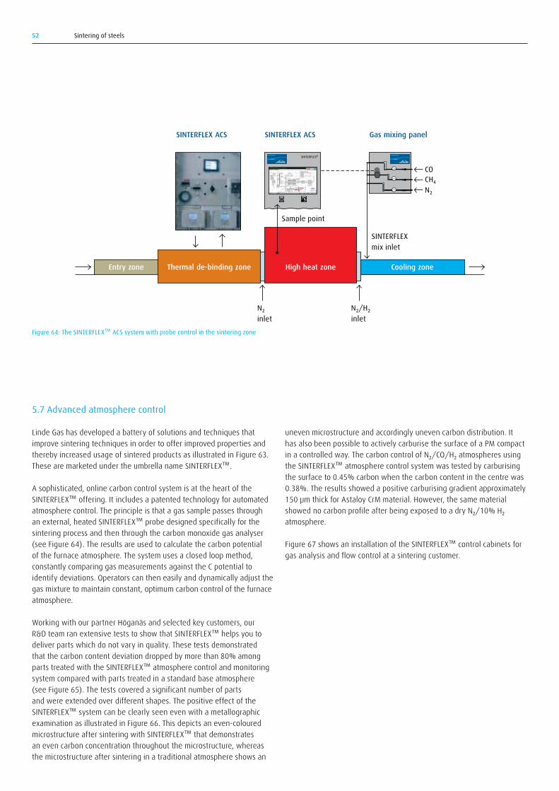
Sintering of steels52
uneven microstructure and accordingly uneven carbon distribution. It has also been possible to actively carburise the surface of a PM compact inacontrolledway.ThecarboncontrolofN₂/CO/H₂atmospheresusingthe SINTERFLEX™ atmosphere control system was tested by carburising the surface to 0.45% carbon when the carbon content in the centre was 0.38%. The results showed a positive carburising gradient approximately 150μmthickforAstaloyCrMmaterial.However,thesamematerialshowednocarbonprofileafterbeingexposedtoadryN₂/10%H₂atmosphere.
Figure 67 shows an installation of the SINTERFLEX™ control cabinets for gas analysis and flow control at a sintering customer.
5.7 Advanced atmosphere control
Linde Gas has developed a battery of solutions and techniques that improve sintering techniques in order to offer improved properties and thereby increased usage of sintered products as illustrated in Figure 63. These are marketed under the umbrella name SINTERFLEX™.
A sophisticated, online carbon control system is at the heart of the SINTERFLEX™ offering. It includes a patented technology for automated atmosphere control. The principle is that a gas sample passes through an external, heated SINTERFLEX™ probe designed specifically for the sintering process and then through the carbon monoxide gas analyser (see Figure 64). The results are used to calculate the carbon potential of the furnace atmosphere. The system uses a closed loop method, constantly comparing gas measurements against the C potential to identify deviations. Operators can then easily and dynamically adjust the gas mixture to maintain constant, optimum carbon control of the furnace atmosphere.
Working with our partner Höganäs and selected key customers, our R&D team ran extensive tests to show that SINTERFLEX™ helps you to deliver parts which do not vary in quality. These tests demonstrated that the carbon content deviation dropped by more than 80% among parts treated with the SINTERFLEX™ atmosphere control and monitoring system compared with parts treated in a standard base atmosphere (see Figure 65). The tests covered a significant number of parts and were extended over different shapes. The positive effect of the SINTERFLEX™ system can be clearly seen even with a metallographic examination as illustrated in Figure 66. This depicts an even-coloured microstructure after sintering with SINTERFLEX™ that demonstrates an even carbon concentration throughout the microstructure, whereas the microstructure after sintering in a traditional atmosphere shows an
Figure 64: The SINTERFLEX™ ACS system with probe control in the sintering zone
PROCESS STOP MAIN SWITCH
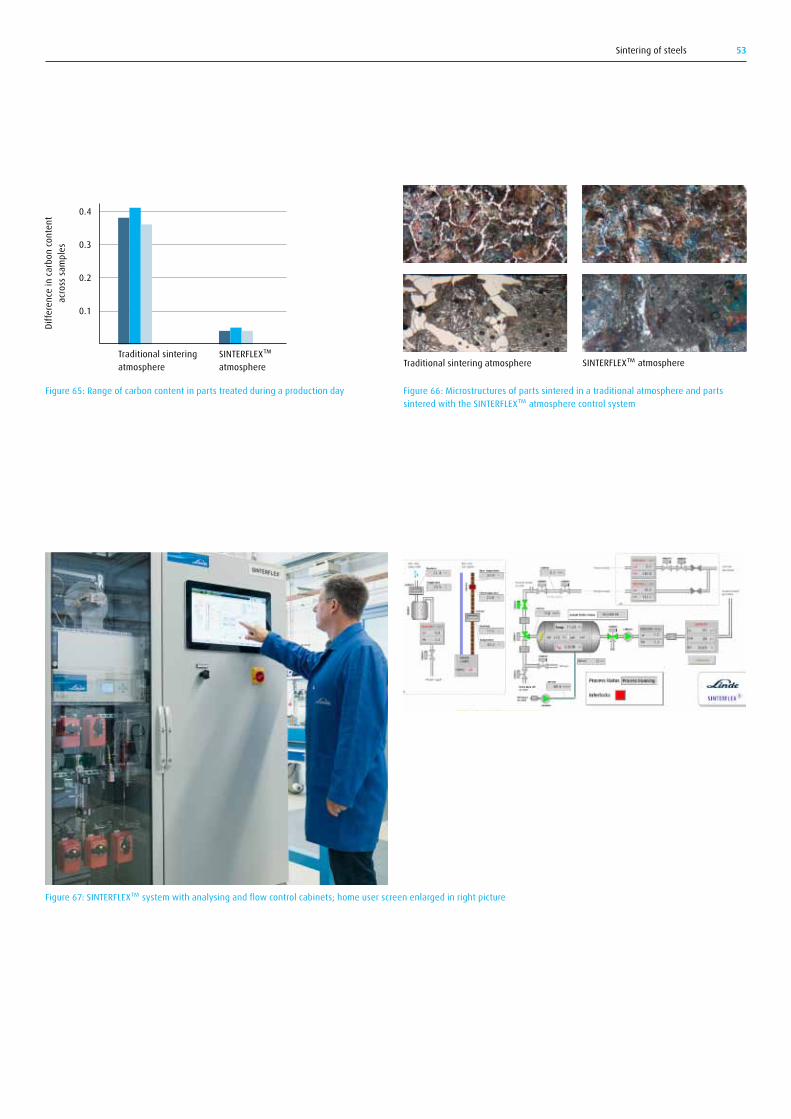
Sintering of steels 53
Figure 65: Range of carbon content in parts treated during a production day Figure 66: Microstructures of parts sintered in a traditional atmosphere and parts sintered with the SINTERFLEX™ atmosphere control system
Figure 67: SINTERFLEX™ system with analysing and flow control cabinets; home user screen enlarged in right picture
Traditional sintering atmosphere
0.4
0.3
0.2
0.1
Diffe
renc
e in
carb
on co
nten
t ac
ross
sam
ples
SINTERFLEX™ atmosphere Traditional sintering atmosphere SINTERFLEX™ atmosphere
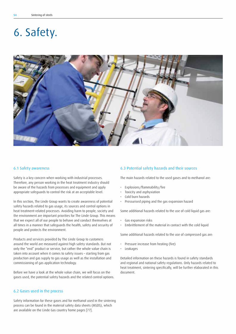
Sintering of steels54
6.1 Safety awareness
Safety is a key concern when working with industrial processes. Therefore, any person working in the heat treatment industry should be aware of the hazards from processes and equipment and apply appropriate safeguards to control the risk at an acceptable level.
In this section, The Linde Group wants to create awareness of potential safety hazards related to gas usage, its sources and control options in heat treatment-related processes. Avoiding harm to people, society and the environment are important priorities for The Linde Group. This means that we expect all of our people to behave and conduct themselves at all times in a manner that safeguards the health, safety and security of people and protects the environment.
Products and services provided by The Linde Group to customers around the world are measured against high safety standards. But not only the “end” product or service, but rather the whole value chain is taken into account when it comes to safety issues – starting from gas production and gas supply to gas usage as well as the installation and commissioning of gas application technology.
Before we have a look at the whole value chain, we will focus on the gases used, the potential safety hazards and the related control options.
6.2 Gases used in the process
Safety information for these gases and for methanol used in the sintering process can be found in the material safety data sheets (MSDS), which are available on the Linde Gas country home pages [77].
6.3 Potential safety hazards and their sources
The main hazards related to the used gases and to methanol are:
• Explosions/flammability/fire• Toxicity and asphyxiation• Cold burn hazards• Pressurised piping and the gas expansion hazard
Some additional hazards related to the use of cold liquid gas are:
• Gas expansion risks • Embrittlement of the material in contact with the cold liquid
Some additional hazards related to the use of compressed gas are:
• Pressure increase from heating (fire)• Leakages
Detailed information on these hazards is found in safety standards and regional and national safety regulations. Only hazards related to heat treatment, sintering specifically, will be further elaborated in this document.
6. Safety.

Sintering of steels 55
Examples of hazards related to the use of heat treatment equipment are:
• Failure of energy supply• Failure of atmosphere gas supply• Flame failure control (burner(s) and pilot(s)) and consequently the
spillage/leakage of asphyxiating gases into the room• Failure/disorder of control systems• Pressure of flow control devices; Low or high temperature detectors• Mechanical hazards such as moving parts, cranes, loading and
unloading equipment, robots, trucks and forklifts, charging doors, rotating shafts, moving rolls or conveyors, hydraulic leaks, etc.
Hazards related to equipment will not be further elaborated in this document. The focus in the following description is on hazards connected with the use of gas.
6.3.1 Explosions/flammability/fireFor ignition or explosion to occur, the following must be present: fuel, oxygen, ignition source (an exclusion here is acetylene which can violently decompose in the absence of oxygen). Flammability risk can be described in relation to the Safety Triangle shown in Figure 68. A triangle of this kind can be devised at a specific temperature and for a specific combustible gas in combination with oxygen. In the shaded area in the middle of this triangle, the gas mixture is flammable. This flammability region broadens as temperature decreases.
The flammable gases commonly found in these atmospheres are hydrogen, carbon monoxide, hydrocarbons, vaporised or dissociated methanol (dissociation produces hydrogen and carbon monoxide), and dissociated ammonia (forms hydrogen and nitrogen).
The European safety standard EN 746-3 [79] gives a more definite description of the flammability range:
“As a general rule, any gas mixture containing more than 5 volume percentcombustiblesH₂+CO+CH₄)ofwhichmethane(CH₄)isnotmorethan 1 volume percent where the remainder of the mixture is non-flammable, is considered to be flammable. Any gas mixture that contains more than 1 volume percent hydrocarbons (CnHm) or 2.5 volume percent ammonia(NH₃)wheretheremainderofthemixtureisnon-flammableisalso considered flammable. A flammable gas which contains 1 volume percent or less oxygen cannot itself form an explosive or flammable mixture.”
The use of nitrogen to ensure safety during start-up and shut-down of furnaces may be illustrated in relation to Figure 68. When starting from an air-filled furnace, corresponding to the top left corner of the diagram, nitrogen is purged into the furnace until the oxygen concentration is lowered to point C. Fuel in the form of combustible gas is then added, which means that the composition is changed along the line C–S–100% fuel. This avoids entering the flammability region L–S–U. When shutting down, the furnace is first purged with nitrogen down to composition B before opening to air. Nitrogen is also used as a purging gas in alarm situations such as failure of electric power or if the furnace temperature falls below the safety temperature.
An explosion will occur if a flammable mixture of atmosphere gas and air has accumulated in a confined area and is suddenly ignited. This danger exists if flammable gases are being used at a process temperature below auto-ignition (750 °C (1382 °F)). The destructive power of the pressure wave from an ignited flammable mixture depends on the amount of gas and the heat of combustion of the fuel gas, the combustion mode, and the configuration of the confinement space. The energy released is absorbed by the surroundings and in the worst case destroys them.
Figure 68: The flammability triangle
Fuel concentration [vol%]
Oxyg
en co
ncen
tratio
n in
gas
mix
ture
[vol
%]
L Lower flammability limit in airU Upper flammability limit in airS Min O2 con. for flammabilityC Start upB Shut down
L
4
8
12
16
B20 40 60 80 100
U
SC
20
00

Sintering of steels56
6.3.4 Pressurised piping and the gas expansion hazardThe nitrogen supplied to the furnaces is under pressure. The gas supply should be locked out from the furnace and the pressure in the lines released in a controlled manner prior to performing maintenance on the system. Failure to do so can lead to unexpected releases of energy or introduction of nitrogen into the furnace. Furthermore, any pipe section designed so that liquid can be trapped inside must be equipped with a safety valve.
6.4 Control of safety hazards
6.4.1 General safety regulations and guidelinesParts of the international safety standard ISO 13577 [78], e.g. part 3 about “Generation and use of protective and reactive atmosphere gases”, are still under development. It has not yet been possible to come to a completely unified agreement between countries on the exact text of the ISO standard, but there are some specific pages describing special requirements for Japan, the USA and the EU. The intention is that the new ISO standard will, when published, replace regional or national standards. However, the existing European and American standards [79–80] as well as other national standards will for some time still serve as guidelines.
6.4.2 Explosions/flammability/fireMeasures to prevent oxygen forming flammable and inherently explosive mixtures with the furnace atmosphere are for instance:
• Maintain a positive furnace pressure by proper gas flow to eliminate the ingress of air into the furnace.
• Vacate the furnace atmosphere from the furnace by controlled combustion of the exit gas.
• Use good natural ventilation, especially when controlled combustion of the exit gas cannot be ensured.
• Use flame curtains and pilot burners at the exhaust when a temperature below 750 °C (1382 °F) does not automatically ignite a flammable mixture.
When using flammable gas mixtures, it is required that the furnace temperature is above the ignition temperature. A safety temperature with good safety margins is therefore used in industrial furnaces. In the European standard [79], the safety temperature is defined at 750 °C (1382 °F). The process temperature for sintering lies above this safety temperature. In the case of a temperature drop due to failure in energy
Possible ignition sources are:
• Surfaces with high temperature such as furnace inner walls, electric heating elements, and burners or burner tubes
• Sparks caused by friction or impact, for instance from fans or electric insulators as well as non-spark-free tools
• Catalysers such as soot, sulfur-containing gases, finely dispersed metal particles, chemical reactions between oxygen and fuel gases, electrostatic charging, and local overheating by soot fire
• Pilot burners and other open burners, lit cigarettes or flame curtains• Adiabatic heat from compression processes
6.3.2 Toxicity and asphyxiationCarbon monoxide is highly poisonous and a concentration as low as 400 ppm is harmful. Carbon monoxide enters the blood and takes the place of oxygen in haemoglobin. Carbon monoxide uptake by the body is very fast, about 250 times faster than oxygen uptake, and even very small CO concentrations can be dangerous. Carbon monoxide has no odour, which makes the hazard more serious. Carbon monoxide has the same density as air and will therefore not disperse naturally. Heat treatment shops should therefore ensure that there is good ventilation in the work areas.
When the oxygen concentration in inhaled air is reduced from 21% to 10%, there is a serious hazard of asphyxiation. Oxygen deficiency can be caused by any asphyxiating gas, the most common being nitrogen. An example of this is when repair or inspection is required in a furnace that has been filled with nitrogen. Whenever entering confined spaces, a risk assessment needs to be carried out beforehand and a rescue plan needs to be in place.
6.3.3 Cold burn hazardsDirect contact with cryogenic liquefied gases such as liquid nitrogen or cold nitrogen vapour will produce effects on the skin similar to burns. Cold burn will also occur when exposed or insufficiently protected parts of the body come into contact with un-insulated pipes or vessels. The skin will stick fast by virtue of the freezing of available moisture, and the flesh will be torn on removal. The wearing of wet clothes should be avoided.
Cold burns can be avoided by use of suitable protective clothing, including leather gloves, boots (trousers should be worn outside the boots), overalls and face shields or goggles as appropriate to the work being carried out.

Sintering of steels 57
supply or electric or burner heating, there must be a control system that automatically closes the valves for flammable gas and opens a valve for nitrogen supply.
When operating heat treatment furnaces below the safety temperature, which is relevant at the inlet and outlet of continuous sintering furnaces, precautions must be taken to ensure that explosive mixtures are not created. A first precaution is to ensure that fuel concentrations are outside the flammability area. This can be realised either by establishing a non-flammable composition all along the furnace or by injecting nitrogen at inlets and outlets to lower the concentration of flammable gases. A further precaution is to avoid or minimise the amount of oxygen in contact with the flammable constituents.
Any commercially fabricated industrial furnace must meet the industrial codes of the company where it will be installed. A number of emergency safety functions should be integrated into the furnace and they should in an emergency situation be able to automatically and safely shut down the furnace. Typical situations would include furnace over-temperature or loss of heating, loss of atmosphere, electric system failure, and flame safety. The manufacturing plant should also train its employees on proper procedures for the unexpected or emergency situations that may arise. Hazard reviews and appropriate documentation are mandatory before starting the operation. Modifications to existing systems should be reviewed with respect to their impact on safety.
Acetylene can present a serious safety hazard, because of its high flammability. Cylinders containing acetylene should be transported, stored and handled properly to ensure they are completely safe. More information is available on the linde-gas.com website.
6.5 Safe use of gases along the value chain
Linde offers various gas supply solutions which can be tailored to the customer’s requirements. As safety is a key concern for Linde, the highest safety standards apply to all gas supply services, the installation of delivery systems and the commissioning of application technology equipment.
Starting with the gas supply to the customer, Linde takes care that every gas supply mode fulfils high safety standards. If the customer requests liquefied gas tank supply for instance, Linde takes the location, its line-up, foundations and floorings, the gas tank itself and the gas supply route into safety considerations.
Regarding gas usage, in the case of oxygen for instance, the customer is instructed in safe gas handling. A risk assessment helps to support the customer in handling industrial gases safely.
Regarding the installation and commissioning of gas application technologies, the customer can expect that a robust equipment safety concept is in place. Furthermore, Linde’s experts can start with a full review of the process landscape and a diagnosis of existing problems including safety risks regarding changes in the operating systems. A plan detailing how to overcome safety issues is created and implemented together with the customer.
The installation and commissioning process includes, where applicable, careful process diagnostics and tailoring of gas consumption to ensure the correct furnace gas atmosphere and distribution. The maintenance of safety-relevant components and a joint risk analysis and hazard review support this common goal. In addition, Linde experts can provide training on all aspects of the installed solution so that plant personnel can operate the system independently. Of course, Linde engineers can be called on afterwards if the customer requires further assistance.
Sintering of steels58
Authors: Michael-Peter Graf, Torsten Holm, Akin Malas, Sören Wiberg
1. Material and Powder Properties, 2004. Höganäs Handbook for Sintered Components, Vol. 1, Höganäs AB, Höganäs.
2. German, R.M., 1996. Sintering Theory and Practice. John Wiley & Sons, New York.
3. Veltl, G., 1995. Sintering and Materials Properties. Proceedings of the EPMA Metal Injection Moulding Course, April 6–7, Bremen.
4. Lindqvist, B., Kanno, K., 2002. Considerations when sintering oxidation-sensitive PM steels, Proceedings of the PM2TEC 2002 Conference, Orlando, Vol. 13, pp. 278-290.
5. International Powder Metallurgy Directory, 2008. 13th edition, Innovar communications.
6. Streicher, E., Renowden, M., Phillips, M., German, R.M., Friedt, J.M., 1992. Atmosphere Role on Binder Degradation During Heat Treatment of Injection Moulded Steels. Heat & Surface ‘92, Kyoto, 17–20 Nov. pp. 285–288.
7. Blände, C-A., Skoglund, G., Tengzelius, J., 1983. Surface hardening – a method to improve various properties of sintered steels. Höganäs iron powder information PM 83-12, Höganäs AB.
8. Mäurer, H-J., 1986. The influence of pore structure on the case-hardening of porous PM steel. Proceedings of the International Powder Metallurgy Conference and Exhibition, Düsseldorf.
9. Bengtsson, S., Marcu, T., Klekovkin, A., June 2008. Carburising of Low-alloyed Chromium Materials – an Overview. Proceedings of the PM2008 World Congress, Washington.
10. Scavino, G., Rosso, M., June 1989. Nitrocarburising of PM materials: Influence of the presence of Cu, S and P. Proceedings of the International PM Conference, San Diego.
11. Production of Sintered Components, 2004. Höganäs Handbook for Sintered Components, Vol. 2, Höganäs AB, Höganäs.
12. Nayar, H., Philips, T., 1991. Nitracolor Process to Improve Corrosion Resistance of Sintered Steel Parts, Advances in Powder Metallurgy, Vol. 3, pp. 75–88.
13. Holm, T., Olsson, P., Troell, E., 2010. Steel and its Heat Treatment, Swerea IVF, Gothenburg.
14. Cremer, I. Personal communication.15. Kanno, K., Takeda, Y., Lindqvist, B., Takahashi, S., Kanda, K., 2002.
Sintering of prealloy 3Cr-0.5Mo steel powder in a carbon/carbon composite mesh belt furnace. Advances in Powder Metallurgy & Particulate materials – 2002, MPIF, Princeton, Vol. 13, pp. 14–22.
16. Vervoort, P.J., Cremer, I., 2000. Debinding and sintering: Batch or continuous. Proceedings of the Euro PM 2000, Sintering and Equipment Conference, Munich.
17. Stratton, P., Viyyuri, S., 2009. Improving the Productivity of a Roller Hearth Furnace with High-speed Gas Injectors. Proceedings of the New Challenges in Heat Treatment and Surface Engineering Conference, (CSHTSE), p. 96.
18. Holm, T., 2007. Linde AG, Furnace Atmospheres No 1, Gas carburising and Carbonitriding. Linde Gas Special Edition, Linde Gas, Munich.
19. Nowotarski, M., May 1987. Atmosphere control in continuous furnaces. Industrial Heating, pp. 34–36.
20. Lindqvist, B. Personal communication.21. German, R.M., 1996. Thermal extraction of binders and lubricants in
sintering. Gas Interactions in Nonferrous Metals Processing, D. Saha (ed.), TMS, Warrendale, pp. 1–15.
22. Saha, D., Apelian, D. Control of de-lubrication utilizing a logistic function based empirical model. Proceedings of the 2001 International Conference on Powder Metallurgy and Particulate Materials, New Orleans, Vol. 5, pp. 103–112.
23. Saha, D., Apelian, D. Optimization of de-lubrication during sintering. Proceedings of the 2000 International Conference on Powder Metallurgy and Particulate Materials, New York, Vol. 5, pp. 183–190
24. Baum, M.M., Becker, R.M., Lappas, A.M., Moss, J.A., Apelian, D., Saha, D., Kapinius, V.A., April 2004. Lubricant pyrolysis during sintering of powder metallurgy compacts. Metallurgical and Materials Transactions B, Vol. 35B, pp. 381–392.
25. Phillips, M., Pourtalet, P., May 1993. Understanding parameters for removal of lubricants from P/M tool steels and stainless steels to improve quality. Industrial Heating, pp. 37–43.
26. Andersson, R., Holm, T., Wiberg, S., 2006. Furnace atmospheres No 2, Neutral hardening and annealing. Linde Gas Special Edition, Linde Gas, Munich.
27. Phillips,M.,Pourtalet,P.,April1992.OptimizingN₂/H₂atmospheresfor P/M lubricant removal. Industrial Heating, pp. 35–38.
28. Renowden, M., Pourtalet, P., 1990. Experimental studies on lubricant Removal. Advances in Powder Metallurgy, Vol. 18, MPIF, Princeton, pp. 261–278.
29. Nayar, H.S., 1984. Production sintering atmospheres. Metals Handbook Vol. 7, Powder Metallurgy, ASM International, Metals Park.
30. Madsac, M., McGeever, J.O., 1987. Computer optimization of nitrogen-based atmospheres for sintering in industrial furnaces. Progress in Powder Metallurgy, MPIF, Princeton, pp. 467–488.
31. Warga, D., 1991. Controlled furnace atmospheres for sintering. PMI (Powder Metallurgy International), Vol. 23, No 5, pp. 317–321.
32. Adams, S., Nayar, H., May 1986. Nitrogen-based sintering – means for increased productivity and quality improvements. Industrial Heating, pp. 22–23.
33. White, G., Nayar, H., 1996. Monitoring of the delubrication process under production conditions. Proceedings of the 1996 World Congress on Powder Metallurgy and Particulate Materials, Washington, June 16–21.
34. Hryha, E., Karamchedu, S., Nyborg, L., 2011. Progress Report – Delubrication Study. Department of Materials & Manufacturing Technology, Chalmers University of Technology, Gothenburg.
35. Danninger, H., Jang, G., Weiss, B., Stickler, R., 1992. Microstructure and mechanical properties of sintered iron, Part 1: basic considerations and review of literature. Powder Metallurgy International, Vol. 25, No 3, pp. 111–117.
36. The Ellingham diagram, www.doitpoms.ac.uk/tlplib/ellingham_diagrams/ellingham.php
37. Thermo-Calc Software, http://www.thermocalc.se/38. FERRONOVA® calculation tools, http://www.ferronova.com39. Hatami, S., Hryha, E., Nyborg, L., Nilsson, D., 2008. Modelling of
sintering atmosphere and microstructural development of chromium alloyed steel. Powder Metallurgy Progress, Vol. 8, No. 2, pp. 115–120.
40. Ryan, D.R., Cuddy, L.J., May 1992. Sintering atmosphere control improves Properties. Heat Treating, pp. 18–22.
41. Micski, A., Uhrenius, B., 1994. The Influence of Sintering Parameters on Homogeneity, Shape Stability and Mechanical Properties of a Sintered Steel. Report IM-3093, Swedish Institute for Metals Research, Stockholm.
References.

Sintering of steels 59
42. Adolfsson, S., 2003. Studies of oxide reduction kinetics during sintering of Fe-3% Cr-0.5% Mo powder in hydrogen. Report IM-2003-125, Swedish Institute for Metals Research, Stockholm (in Swedish).
43. Wikman, S., 2004. Decarburisation and carburisation reactions during Sintering. Report KIMAB-2004-128, Swerea KIMAB AB, Stockholm.
44. Caddéo, S., Frisk, K., 2007. Surface oxides studies on powders utilising PAS. Report KIMAB-2007-129, Swerea KIMAB AB, Stockholm.
45. Bergman, O., Nyborg, L., 2010. Evaluation of sintered properties of PM steels based on Cr and Cr-Mn prealloyed steel powders. Powder Metallurgy Progress, Vol. 10, No 1, pp. 1–19.
46. Bergman, O., Frisk, K., Nyborg, L., Oct. 2009. Analysis of oxide reduction during sintering of Cr-alloyed steel powder through photoacoustic spectroscopy measurements. Proc. of Euro PM2009, Copenhagen, EPMA, Vol. 3, pp. 239–244.
47. Caddéo, S., Frisk, K., 2008. Carbon control during high temperature sintering. Report KIMAB-2008-111, Swerea KIMAB AB, Stockholm.
48. Hryha, E., Dudrova, E., Nyborg, L., November 2010. Critical aspects of alloying of sintered steels with manganese. Metallurgical and Materials Transactions A, Vol. 41A, pp. 2880–2897.
49. Arvidsson, J., Oct. 1998. Proceedings of the PM World Conference, Granada, Spain.
50. Eudier, M., 1981. Role of atmosphere in sintering of copper steels. Powder Metallurgy, No 3, pp. 151–154.
51. Norden, C., Wiberg, S., Oct. 1998. Optimisation of properties of sintered P/M steels by statistical modelling. Proceedings of the PM World Conference, Granada, Spain.
52. Garg, D., Berger, K.R., Plicht, G., 1991. Decarb-free sintering of Fe-C components. Metal Powder Report, November, pp. 30–34.
53. Alms, U., Arnhold, V., Bockel-Macal, S., Bruchet, P., Speaker, R.F., 13–17 May 2001. Status of sintering atmospheres for mass production of PM components: technologies, quality, cost. Advances in Powder Metallurgy and Particulate Materials, New Orleans, pp. 5:1–8.
54. Grabke, H.J., 1990. Carburising kinetics. Härterei Technische Mitteilungen, No 45, pp. 110–118 (in German).
55. Williams, D.S., Möller, R., Grabke, H.J., 1981. Steady state carbon activityonnickelandironinflowingCH₄-H₂-H₂Omixtures.High Temperature Science, Vol. 14, pp. 33–50.
56. Nash, P., Wen, C-J., Philips, M., Lumpkins, E. The influence of a N₂/10%H₂AtmosphereontheSinteringandtheMechanicalProperties of FC0208.
57. Bowe, D.J., Berger, K.R., Marsden, J.G., Garg, D., 1995. Optimization of nitrogen/hydrogen sintering atmosphere composition for carbon steel. The int. journal of powder metallurgy, Vol. 31, No 1, pp. 29–35.
58. Sibley, A.T., Ellison, T.L., December 1981. Effects of nitrogen content on the properties of ferrous compacts sintered in nitrogen containing atmosphere. Industrial Heating, pp. 29–31.
59. Cias, A., Mitchell, S.C., Wronski, A.S. Mechanical properties of chromium PM steel sintered in technical nitrogen. Proceedings of the Euro PM 2004, Sintering Conference, pp. 5–10.
60. Bergman, O., 2001. Effects of nitrogen uptake during sintering on the properties of LM steels prealloyed with chromium. Report KIMAB-2001-540, Swerea KIMAB AB, Stockholm.
61. Blais, C., Serafini, R., L’Esperance, G., 2005. Effect of hydrogen concentration in cooling zone on sinter hardening. International Journal of Powder Metallurgy, Vol. 41, No 4, pp. 33–41.
62. Lawley, A., Stiles, D., Marucci, M.L., Causton, R. Effect of Porosity on Thermal Response, Hardness, Hardenability and Microstructure of P/M steel. Technical Report 123, Hoeganaes Corporation.
63. Segerberg, S., Troell, E., 2002. Carburising and cooling of sinter steel. IVF report 02005, IVF, Gothenburg (in Swedish).
64. Hatami S., Malakizadi, A., Nyborg, L., Wallin, D. Critical aspects of sinter-hardening of prealloyed Cr-Mo steel. Journal of Materials Processing Technology, 210 (9), pp. 1180–1189.
65. Samal, P.K., Klar, E., Nasser, S.A., 1997. Effect of sintering atmosphere on corrosion resistance and mechanical properties of austenitic stainless steels – part 1. Proceedings of the International PM Conference 1997, Chicago, 14:55–14:65.
66. Holm, T., January/February 2007. Development Trends —Controlled Furnace Atmospheres. Heat Treating Progress, pp. 25–28.
67. Krug, S., Zachmann, S., Dec 2009. Influence of sintering conditions and furnace technology on chemical and mechanical properties of injection moulded 316L. Powder Injection Moulding International, Vol. 3 (4), pp. 66–70.
68. Talacchia, S., Amador, J., Urcola, J., June 1995. Novel high speed steels sintered below 1150 °C. Metal Powder Report, pp. 16–20.
69. Urrutibeaskoa, I., Jauregi, S., Fernandez, F., Talacchia, S., Palma, R., Martinez, V., Urcola, J., 1993. Improved sintering response of vanadium-rich high speed steels. The International Journal of Powder Metallurgy, Vol. 29, No 4, pp. 367–378.
70. Schaffer, G.B., Sercombe, T.B., Huo, S.H., Hall, B.J., Spranklin, J.A. Atmosphere Effects in the Sintering of Aluminium. EURO PM 2004, Proceedings of the 2004 PM World Congress, Vienna, European Powder Metallurgy Association, pp. 11–16.
71. Holm, T., 2005. Furnace Atmospheres No 4, Brazing. Linde Gas Special Edition, Linde Gas, Munich.
72. Beiss, P., October 2000. Control of Protective Atmospheres during Sintering. Proceedings Euro PM 2000 – Sintering and Equipment, Munich, pp. 147–157.
73. Grohowski, J.A., Strauss, J.T., June 2002. Effect of atmospheric pressure on thermal debinding rate behaviour. Proceedings of PM World Materials Congress, Orlando, pp. 10:109–10:116.
74. Robinson, S.K., June 2002. Debinding metal and ceramic MIM components in batch furnaces using vacuum/controlled atmospheres. Proceedings of PM World Materials Congress, Orlando, pp. 10:94–10:108.
75. Bauer, R.E. Overpressure Sintering Furnaces VKPgr – Dewaxing Sintering and Compacting in a Combined Cycle. ALD Vacuum Technologies technical Information, E153e/7.95/1000/T&D.
76. Laumen, C., Wiberg, S., Andersson, R., Pardo, X., Tarrats, E., February 1999. On-line control of synthetic sintering atmospheres. Metal Powder Report, Vol. 54, No 2, pp. 41 ff.
77. ISO 13577-3 Industrial furnaces and associated processing equipment — Safety — Part 3: Generation and use of protective and reactive atmosphere gases (in development, not published).
78. EN-746-3, 1997: Industrial thermoprocessing equipment – Part 3: Safety requirements for the generation and use of atmosphere gases.
79. NFPA 86C, Standard for Industrial Furnaces Using a Special Processing Atmosphere. This standard is incorporated in and replaced by the 2003 edition of NFPA 86.
80. Holm, T., 2009. Furnace Atmospheres No 3, Gas nitriding and Nitrocarburising. Linde Gas Special Edition, Linde Gas, Munich.

Linde AGGases Division, Carl-von-Linde-Strasse 25, 85716 Unterschleissheim, Germany Phone +49 89 31001-0, [email protected], www.linde-gas.com/heattreatment