Embed Size (px)
Citation preview

13th World Conference on Earthquake Engineering Vancouver, B.C., Canada
August 1-6, 2004 Paper No. 2885
FULL SCALE ON LINE TEST ON TWO STORY MASONRY BUILDING USING HANDMADE BRICKS
Carlos ZAVALA1, Claudia HONMA2, Patricia GIBU3, Jorge GALLARDO4, Guillermo HUACO5
SUMMARY Masonry is the likely used material to build housing in developing countries. Most of bricks are not produced in factories, so handmade bricks don’t have the appropriate resistance according with standards. In order to investigate the behavior of masonry under such conditions, a full scale on line test on two story masonry building using handmade bricks was carried out in the structure laboratory of CISMID/FIC/UNI. Three actuators under mix control drive the structure under prefixed displacement pattern. The actuators displacement reproduced a first mode configuration. The testing experiment torsion during its performance and good behavior even handmade bricks was used. Final stage of the building was found under story drift of 1/65 for a base shear of 147.86 t. Cracking pattern related with drift response is presented for this kind of building
INTRODUCTION Peru is located in the central part of South America with mixture of cultures and cities with their own way for design and build a house. Since ancient times the masonry has been the most likely used material selected by the Peruvian Population. Stone block masonry and adobe block masonry has been used since Inka’s times. Many historical buildings show good state in conservation due to the high wall density used by our old constructors. However after the experience of strong quakes in Cuzco and Lima, builders improved their technologies and rebuilt many of the historical buildings. Also in times of the Spanish colony, clay brick masonry started to be used in church construction and also in housing. Since that times many improvements have been developed in our culture. The first recommendation of quake considerations appears in the 60’s and after the experience of 1966 Lima quake and 1970 quake, the first version of National Standards for earthquake resistant design appears in 1977. After 1996 Nazca quake, modification on the standards considering displacement control of the structure was a great improve in our code publish in 1997 [1]. The current standard was published in April 2003, including a modification in the reduction factors
1 Chief Structural Lab, Associate Professor CISMID/ FIC/ UNI ,Lima Peru, Email: [email protected] 2 Assistant Researcher, Structural Lab, CISMID/ FIC/ UNI ,Lima Peru 3 Assistant Professor CISMID/ FIC/ UNI ,Lima Peru 4 Chief Earthquake Engineering Division, Associate Professor CISMID/ FIC/ UNI ,Lima Peru 5 Graduate Student CISMID/ FIC/ UNI ,Lima Peru

The total shear force acting in the base of the structure, corresponding to the direction considered in the test, will be determined through the following expression:
VZUSC
RP=
where Z is the zoning factor, U is the building category factor, S is the site condition factor, C is the seismic amplification factor, P is the weight of the structure and R is the reduction factor. In this report a two story building designed using the above seismic demand and following the Peruvian confined masonry standards is tested against lateral cyclic loading using an on-line actuator system. The house was built on real soil and real interaction was monitored during the test execution. The house was built with handmade bricks where the comparison of behavior with factory brick is presented in wall cyclic test. The construction process was monitoring and each stage of the construction follow the quality control standards. So it will show even a handmade brick is used (with not guarantee in quality control in fabrication and resistance) earthquake resistance building is reached to satisfied the quake demand.
THE MASONRY STANDARDS The construction and allowable stress of this structural system is rule by the Peruvian Standards E-70 SENCICO [2], of 1982. Minimum values of stress of walls and units are given in this code. More of the values has been affected by high security factors to prevent the poor quality control on handmade units, which are likely used in expansion areas of the urban zones, like shine towns. Table 1 presents the minimum values of allowable stresses of the Peruvian Standards.
TABLE 1: Allowable stresses in masonry Stress Type Formula (Kg/cm2)
Compression due to axial load in Walls Fa=0.20 f’m f’m: compression resistance of masonry
Compression due to bending Fm=0.40 f’m Tension due to Bending - Normal to horizontal joints
Ft=1.00
Shear Vm=1.2+0.18fd < 2.7 fd: dead load normal stress
Crushing on Masonry - In whole area - In 1/ 3 of area
Fca=0.25 f’m Fca=0.37 f’m
Elastic Modulus Shear Modulus
Em= 500 f’m Ev=0.4 Em
Actually a new Peruvian Standard E-070 [3] and [4] is under discussion. The proposal considers the verification of each of the icons critical stages of the behavior of each wall. These are the axial capacity, the initial cracking stage and finally the diagonal crack capacity of the wall. Also, two levels of quake must be verified for the masonry building under the new standard:
- Severe damage quake: design quake NT-030 (V) - Moderate damage quake: likely occur quake with half of the shear demand of design
quake(Ve = V/2). According with the proposal masonry standards NTE-070 the maximum axial stress must be computed by: σm = Pm / (L t) ≤ 0.20 f’m [ 1- (h/35t)2] ≤ 0.15 f’m
where L = total lenght of wall including columns t = thickness of the wall

Pm= gravity load including 100% of live load h = free length between horizontal bracing elements
f’m= compression stress of masonry Cracking resistance depends on the diagonal craking capacity of the wall in the proposal of standards shear demands for a wall under a moderate quake(Ve) should verify the following equation:
Ve ≤ 0.55 Vm Where Vm is shear capacity associated with diagonal cracking of the masonry wall.
The value of Vm is a function of the slenderness reduction factor “α” of the wall, the wall dimensions (thickness “t” and length “L”) and the gravity load “Pg” (with reduced live load NTE-030) and the resistance to diagonal tension “v’m”. In the case of brick masonry blocks of clay or concrete, Vm is computed as:
Vm= 0.5 v’m α t L + 0.23 Pg Here v’m could be approximate as: v’m = √ f’m
The slenderness reduction factor is computed as: α = Ve L / Me where Ve is the shear demand of the wall and Me is the bending moment of the wall as a result of an static analysis.
Also must satisfied: 0.33 ≤ α ≤ 1.00
THE TESTED BUILDING
Figure 1 presents the architectural drawing of two stories testing building. This house represents a likely used distribution for six family members and have all facilities for living. The house was built using handmade clay bricks taken from a representative sample from common informal sellers in surroundings north Lima’s suburbs. Story height of the house is 2500 mm.. Samples of the material were taken and piles of 4 clay bricks were subjected to compression test for determine the resistance of masonry. Table 2 show the results for the used handmade bricks and also the factory bricks for comparison
FIGURE 1: Architectural distribution of testing house (←North South→)

TABLE 2: Masonry compression strength of clay bricks
The building was designed following the Peruvian earthquake design Standards NT-E030 and the masonry standards NT-E070. Under these standards Table 3 presents the computed design quake demand for the building where design quake acceleration was 267 gals. Table 3 presents the results for the demand of the quake in each of the directions of the building. Test forces application was in direction X-X, which is parallel to the longest length of the building as is presented in Figure 1.
TABLE 3: Design Quake demand for each axis Story Height (m.) Weight (t.) Weight x Height Fi (t.)= Static Equivalent Force XX
2 5.30 51 270.3 18.5 1 2.50 51 127.5 8.7 397.8 27.3t.
Story Height (m.) Weight (t.) Weight x Height Fi (t.)= Static Equivalent Force YY
2 5.30 51 270.3 37.1 1 2.50 51 127.5 17.5 397.8 54.6t.
FIGURE 2: The building under construction
AverageBrick Type Sample Pmax Area Stress F'm
(kg) (cm2) (kg/cm2) (kg/cm2)M1 9500.00 238.05 39.91
Handmade M2 9500.00 253.20 37.52M3 13225.00 228.00 58.00M4 13225.00 235.75 56.10M5 10375.00 228.00 45.50
M6 20975.00 303.15 69.19Factory made M7 17325.00 312.84 55.38
M8 20575.00 300.80 68.40M9 27000.00 306.80 88.01
47.41
70.24
It can be read that in direction Y-Y the base shear force is bigger than X-X direction. This is because in Y-Y direction the reduction factor is R=2.25 because only masonry walls are presented. In direction X-X R=4.5 because masonry walls and one concrete shear wall were used. The concrete shear wall was included because according to masonry standards NT-E070, the minimum wall density for seismic safety building is 4%. Therefore because this ratio was not satisfied, additional concrete element was considered to reach an appropriate stiffness and minimum wall density.
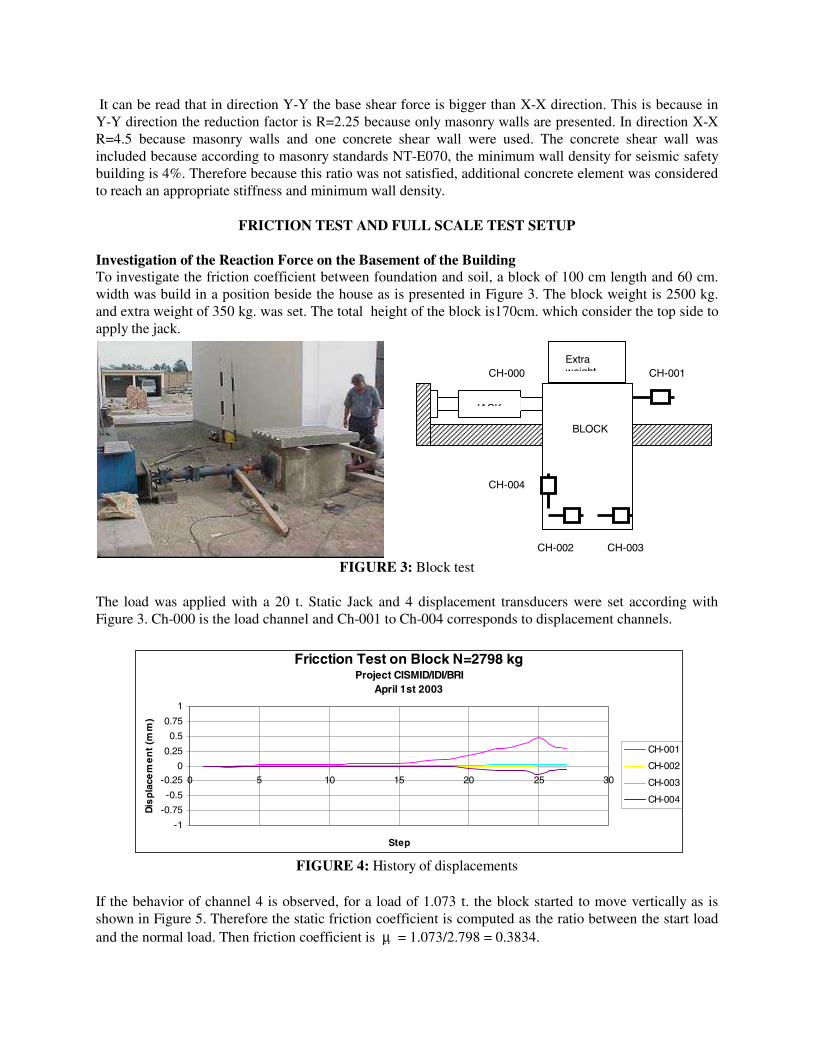
FRICTION TEST AND FULL SCALE TEST SETUP Investigation of the Reaction Force on the Basement of the Building To investigate the friction coefficient between foundation and soil, a block of 100 cm length and 60 cm. width was build in a position beside the house as is presented in Figure 3. The block weight is 2500 kg. and extra weight of 350 kg. was set. The total height of the block is170cm. which consider the top side to apply the jack.
FIGURE 3: Block test
The load was applied with a 20 t. Static Jack and 4 displacement transducers were set according with Figure 3. Ch-000 is the load channel and Ch-001 to Ch-004 corresponds to displacement channels.
FIGURE 4: History of displacements If the behavior of channel 4 is observed, for a load of 1.073 t. the block started to move vertically as is shown in Figure 5. Therefore the static friction coefficient is computed as the ratio between the start load and the normal load. Then friction coefficient is µ = 1.073/2.798 = 0.3834.
CH-000 CH-001
CH-004
CH-002 CH-003
JACK
BLOCK
Extra weight
Fricction Test on Block N=2798 kgProject CISMID/IDI/BRI
April 1st 2003
-1
-0.75
-0.5
-0.25
0
0.25
0.5
0.75
1
0 5 10 15 20 25 30
Step
Dis
pla
cem
en
t (m
m)
CH-001
CH-002
CH-003
CH-004

If the normal load of the masonry house including the footing is 175 t., the load to produce the lift of the building is Vmax = µ x 175 = 67.1 t. as a base shear. According with the analysis presented above maximum shear load of 54.6 t. is demand for the design quake. However the resistance of the building is 61.82 t. After the block investigation is possible to assure a threshold load of 67 t as a base shear will not produce displacement or lift on the building. After this threshold value, a correction in the lateral displacement should be performing in order to have the real behavior of the house without influence of the footing displacement.
FIGURE 5: Load – displacements on block Loading Mechanism for Full scale house test In order to develop a cyclic test on the full scale confined masonry house, the procedure proposed by the standard ASTM E564-00e1 Standard Practice for Static Load Test for Shear Resistance of Framed Walls for Buildings have been adapted for this experiment. Considering the possibility of torsion on the house and mitigation the problems for the loading on the experiment using an external support structure as shows in Figure 6. Control load Equipment and Measuring s To develop the test, three actuators of 25 t. of capacity were used. Two actuators on the second floor and one actuator on the first floor were in position to push and pull the full-scale specimen. The actuators were working under a mix control; this is one actuator on the second floor under displacement control (let’s name it command actuator) and the others two actuators under load control using the signal from the command actuator. All the actuators work under a stroke range of 200 mm. A computer through a servopulser controlled the actuators. Signal conditioner was used for the acquisition of the signals of each sensor. A set of 45 sensors were set and two measuring systems were used: first a signal conditioner with 16 channels and UCAM 5BT static measuring system using 29 channels. The command actuator is driven to produce the following drift values: 1/3200, 1/1600,1/800,1/400,1/200, 1/100, 1/75.
Fricction Test on Block N=2798 kgProject CISMID/IDI/BRI
April 1st 2003
-1.8
-1.6
-1.4
-1.2
-1
-0.8
-0.6
-0.4
-0.2
0
0.2
-0.2 0 0.2 0.4 0.6
displacement (mm)
Loa
d (t
f)
CH-01
CH-02
CH-03
CH-04

FIGURE 6: Test setup of the testing house
TEST RESULTS Using three actuators, a command actuator with stroke control and two actuators under load control, the test was performed successfully. For each of the story drift ratio measured on the top, the specimen was drive in cyclically producing deterioration on the walls and confinement under high drift ratios.
It was observed that the structure behaves elastically till 1/1600 drift is reached. After drift 1/800 cracking on walls started. High deterioration occurs under a drift of 1/200 and the maximum deterioration happens at a drift of 1/75.
FIGURE 7: First Floor displacement versus Base shear
Project CISMID/FIC/UNI- IDIFull scale Two story House Test
June 8th, 9th, 10th 2003
-150
-100
-50
0
50
100
150
-80 -60 -40 -20 0 20 40 60 80
First Floor Displacement (mm)
Bas
e S
he
ar (
tf.)
x1-north CH-100 x1-center

Project CISMID/FIC/UNI- IDIFull scale Two story House Test
June 8th, 9th, 10th 2003
-150
-100
-50
0
50
100
150
-80 -60 -40 -20 0 20 40 60 80
Roof Displacement (mm)
Ba
se S
he
ar
(tf.
)
CH-102 CH-103 CH-101
FIGURE 8: First floor displacement history
Figure 7 and Figure 8 shows displacement - shear relations on the first and second floors. Here each of the sensors is related with the main axis for walls in the direction of the test. It is possible to read that small torsion is induced because there are difference between each of the sensors on this direction. This is confirmed in Figure 9 where measure rotation is presented. The rotation angle on the top floor has maximum value of 0.0035 radians that was reached for the maximum drift
Project CISMID/FIC/UNI- IDIFull scale Two story House Test
June 8th, 9th, 10th 2003
-150
-100
-50
0
50
100
150
-5 -4 -3 -2 -1 0 1 2 3 4 5
Rotationon roof x 10-3
Ba
se S
he
ar
(tf.
)
Rotation
FIGURE 9: measured rotation on roof

Project CISMID/FIC/UNI- IDIFull scale Two story House Test
June 8th, 9th, 10th 2003
-10
-8
-6
-4
-2
0
2
4
6
8
10
0 100 200 300 400 500 600 700 800
Step
Ver
tical
Dis
plac
emen
t 25
mm
fro
m
base
(m
m)
CH-107 CH-108 CH-109 CH-110
FIGURE 10: Vertical displacement at level 25 mm. from basement
Figure 10 presents the vertical displacement at level 25 mm. from basement. By observation of Figure 10 is possible to read that after step 250, the base shear of the house reach the friction resistance value and the lateral displacement will include the displacement of the basement due to resistance of soil is overpassed. Therefore, a correction on the displacement was performed on the curves presented in Figure 7 and 8. The results of the test after this correction are presented in Figure 11 and 12.
FIGURE 11: First Floor displacement versus base shear with base displacement correction
Project CISMID/FIC/UNI- IDIFull scale Two story House Test
June 8th, 9th, 10th 2003with base displacement correction
-150
-100
-50
0
50
100
150
-80 -60 -40 -20 0 20 40 60 80
First Floor Displacement (mm)
Bas
e S
he
ar (
tf.)
x1c-north x1c-south x1c-center

Project CISMID/FIC/UNI- IDIFull scale Two story House Test
June 8th, 9th, 10th 2003with base displacement correction
-150
-100
-50
0
50
100
150
-80 -60 -40 -20 0 20 40 60 80
Roof Displacement (mm)
Bas
e S
he
ar (
tf.)
x2c-center x2c-south x2c-north
FIGURE 12: Second floor load - displacement corrected
Using the peak values for each of the applied loading cycles of Figure 11 and Figure 12, the behavior curves of each floor is built. Figure 13 and Figure 14 presents the behavior curves for first and second floor respectively. It is possible to read from Figure13; Then, the displacement of the central part of the structure became smaller than the south and north sides. However the south side have bigger displacement because the torsion effect (irregularity in plan of the structure). Then the building has more displacement in the south side than in the north one, as is expected. A maximum drift of 1/140 in the south side was reach on the first floor and 1/250 on north side when actuator pulls the specimen. By the other side when actuator push the specimen maximum drift of 1/65 and 1/250 was reach for south and north sides
Because security of our equipment’s we decide to push the specimen on the last step because the loading beam for 1/100 drift had a displacement near 40 mm. We imagine if pull condition could damage the loading frame an accident will occur so under this consideration the specimen was pushed with the actuators and reach its failure for a drift of 1/65 under a base shear of 147.86 t.
FIGURE 13: Behavior curve on first floor
Project CISMID/FIC/UNI- IDIFull scale Two story House Test - First Floor
June 8th, 9th, 10th 2003
-150
-100
-50
0
50
100
150
-0.020 -0.015 -0.010 -0.005 0.000 0.005 0.010 0.015 0.020
drift on first floor
Bas
e sh
ear
(tf)
x1c-north x1c-center x1c-south

Project CISMID/FIC/UNI- IDIFull scale Two story House Test - First Floor
June 8th, 9th, 10th 2003
-150
-100
-50
0
50
100
150
-0.020 -0.015 -0.010 -0.005 0.000 0.005 0.010 0.015 0.020
drift on second floor
Ro
of
sh
ear
(tf
)
x2-north x2c-center x2-south
FIGURE 14: Behavior curve on second floor
CONCLUSIONS - For application of displacement to the specimen a three-actuator system of CISMID Structural Lab
was used. Two actuators were set on the second floor and one actuator on the first floor level. One actuator was set under displacement control and the signal of the feedback load was by passed to the others to actuators. By this method a load of 2P was applied on the second level and a load of P was applied on the first floor. This configuration simulated a displacement pattern similar to the first mode of vibration of the structure.
- The displacement was applied to the specimen and a data acquisition system scanned measurements from transducers, load cells and strain gauges. Cyclic displacement was applied under the defined pattern of inter-story drift.
- Initial cracking of the specimen starts for a drift of 1/1600 with cracks of 0.05~0.10 mm. and become notorious after 1/800 when cracks of 1.2 mm. appeared. A maximum base shear 147.86 t. was the failure load of the specimen under a drift of 1/65 with cracks from side between 5~10 mm. in thickness.
- After a base shear of 67 t., the specimen a translation on the specimen base ocurred. Then, correction on lateral displacement is performed in order to find the appropriated behavior curves.
- Behavior curves are presented in Figure 13 and Figure 14 for first and second floor of the building. Here it is possible to read how the displacement in the south side of the specimen is bigger than the dsiplacement of north side. Is obvious influence of the torsion effect was verified in Figure 9 where rotation on roof was reported. Then specimen rotates to the south side because north side has bigger stiffness than the south side.
Table 4: Maximum Drift on capacity of initial cracking Vx(kg) δx i (cm) ∆xi /h Story 1 23457.07 0.516367 0.00207
Table 5: Maximum Drift on the capacity of
diagonal cracking Vx(kg) δx i (cm) ∆xi/h Story 1 42649.23 0.687300 0.00275
- Considering that the actuator pushing behavior curve represents the performance of the structural
system, the required demand for severe quake and the required demand for moderate quake is

107123
168
168
186
143 151 151
8657
107
107
86
123
123
16812
3
151
143
107
123
123
123
123 168
123
168
168
151
186
151186
151151
143
143
207
2072
07
284
207
207
207
235
235
248
284207
207
207
248
282
20720 7
207284
248207
302
248
248
235
207
168
284
248
248
186
302
248
123
248248
248
235
207
207
207
207
207
302
302302
248 248
302
302
302
302
302
302
302
302
349
349
349
34 9 349
323
323323
323
373
284
323
323
373
323
323
323
349
349
284
323323
323
373
349
349
349
349
323
323
323
495
3 23 32 3
40 0
349
349
349323
323
349
323
400400
349
373
349
465
3 23
349
323
323
3 49
34 9
349
349
400
400
323
323
323
349349
323
323
349
349
400400
400
400349
323
323
323
323
323
323
323323323
323
323
349
400
400
400
400
400
323323
349
323
3 23 3 7
3
323
3 73
373
373
323
373
373
373
373
349 400
323
323323
323
323
323
373
373373
323
349
349
349
400 349
433495
433
495
433
433
495
525
465
495
525 433
430
433
495
430
430
430
430
495
525
4 6 5
433433
433
433433
495
430
430
495 43
0
430
465
495
433
495
495
430495
430
495
495
433
495495
465
430
430
430
433433
465
495
465525
525465
465465
465
465
465
465465
465
465465
465
495
4 95
495
495
433
465
495
323
495433
430
4 95
495
495
207
495
495
430
430 43
0
525
465
4 30
433
495
433
433
430
430
430
465
433465
465430465
495430
495
433
430
430
525
52 5
430
330
5 25 465
465
46 5
52 5
46 5
465 46 546 5
46 5
34 9465465525
433
433
207
433433
495495
433
430
430
433
465
465
433
430
430
495
495465
4654 00
430
433
465
465
433
465
465 433
430
430
433
439495
495
430
430495
430
430
4 30
495
495
495
495495495
495 525
349
465433465
465525
465
465
525
465
525
465
433 430
495
495
4 30
465
525
465
525
525
43 3
4 30
4 33465
43 0
433
433
465 465
465
465
465
525
525
525
525
495
525
525
525
495433
495433
325465
465
430
495
465
495
495
495
495
430
430
430
430
430
495
430495 495
430
433495
495495
433
495 430
495
433433
525
525
525
465
465
430
495
495
430
495
433495
86
525
186
302349
373
373
373430
433
557
557
557
495430
495
433
430
430
525
52 5
430
330
525 465
465
4 65
52 5
46 5
465 4 65465
46 5
349465465
52 5
433
433
207
433433
495
495
433
430
430
433
465
465
433
430
430
495
495465
46540 0
430
433
465
465
433
465
465 433
430
430
433
439
495
495
430
430495
430
430
430
495
495
495
495495495
495 525
34 9
465433465
465525
465
465
525
465
5 25
465
433 430
495
495
430
465
525
4 65
525
525
433
430
433465
430
433
433
465
465
465
465
46 5
525
525
525
5 25
495
525
525
525
4 95433
4954 33
325465
465
430
495
465
495
495
495
495
430
430
430
430
430
4 95
430
4 30
433
495 495430
433495
495
495
433
495 430
495
433433
525525
525
465
465
430
495
495
430
495
433495
636
590590
590
615
6 15
557590 557
662 557557
557
557
557
557
557
615
557
557
590
590
59 0
6 15
557
557
465
590
557
557
557
590
59 0
557
590557
557
557
557
5 57
636
557
636
615
557
557
59 0590
636
5906 36
590
4 30
6 15
590
557615
557
590
590
590
590
557
557
557
557
557
615
52 5
615
557
557
557
636590
636636
590
590
636
557557
557
557
557
557
557 590
636
557
557
557
557
557
557557
557
636
636
615557
557
6 15
557
557
590
590
590
590
590
590
590
590
590
570
590
636
590 557
615
557
615 557
61555
7
557
557
5 57
5 57
5 77
590
590
615
557
557
557
557
557
615
557557
590
636
590590
590636
590
557
557
557
6 36
6 36
557
636
636
636
4 30430
557
557
557
615
557
557
636590
590
636 636590636
59 0
5 90
590
636
59 0
557
557
636
636
636
615
615
615
615615
615
590
590
590
590
6 15
662662
6 62
662
662
6 62
662
662
662
662
6 62
662662
662
662
6 62
6 62
662
662
662
662
662
6 62
662
615
86 107123
168
168
186
143 151 151
8657
107
1 07
86
123
123
16812
3
151
143
107
123
123
123
123 168
123
168
168
151
186
1 86
151186
151151
143
143
207
2072
07
2 84
2 07
2 07
207
235
235
248
284207
2 07
207
248
282
2072 07
207284
2482 07
302
248
248
235
207
168
284
248
248
186
302
248
123
248248
248
235
302
207
207
207
207
207
302
302302
248 248
302
302
302
302
302
302
302
302
349
349
349
349 349
323
323323
323
373
284
323
323
373
323
323
323
349
349
284
3233 23
323
373
349
349
349
3 49
323
323
323
495
3 23 32 3
4 00
3493 49
349323
323349
323
400400
3 49
373
349
46 5349
3 23
349
323
3 23
349
349
349
349
400
400
323
323
323
3493 49
323
323
349
349
400400
400
40034 9
323
323
323
323
323
323
323
323323
323
323
3 49
400
400
400
400
400
323323
349
323
3 23 37
3
323
3 73
373
373
323
373
373
373
373
373
349 400
323
323323
323
323
323373
373373
323
349
349
349
400 349
433495
433
495
433
433
495
525
465
495
525 433
430
433
495
430
430
430
430
495
525
46 5
433433
433
433433
495
430
430
4 95 43
0
430
4 65
4 95
433
495
495
430495
430
495
495
433
495495
465
4 30
4 30
430
433433
465
495
4 65525
525465
4 65557
465
465
465
4 654 65
465
465465
465
495
495
495
495
433
465
495
3 23
495433
430
495
495
495
207
495
495
4 30
430 43
0
525
465
430
433
495
433
433
430
4 30
465
4334 654 65
430465
presented in Figure 15. Considering the diagnosis by capacity design values from Table 4 and 5 we found the values of the standards are in a safety range.
Figure 15: Design require demand points and cyclic behavior on full scale house
- Cracking pattern performed during the test is presented in [5]. Figure 16 shows some cracking patterns in south wing of the building. Here its is possible to understand the meaning of each of the drift values and verify that with 1/200 value the structure could be repair even a considerable cracking appears on walls.
1/800 1/200
1/100 1/65
FIGURE 16: Crack Pattern during test
Project CISMID/FIC/UNI- IDIFull scale Tw o story House Test - First Floor
June 8th, 9th, 10th 2003
0
25
50
75
100
125
150
0.000 0.005 0.010 0.015 0.020drift on first floor
Bas
e s
he
ar (
tf)
x1c-north x1c-centerx1c-south initial crackingDiagonal Cracking
207
86107
123
168
168
186
143 151 151
86 57
107
107
86
123
123
16812
3
151
1 43
107
123
123
123
12316
8
123
168
168
151
186
151
186
151151
143
143
207
207
207
284
207
207
207
235
235
248
284207
207
207
248
282
2072 07
207284
248
207 302
248
248
235
207
168
284
248
248
186
302
248
123
248248
248
235
207
207
207
207
207
302
302302
248 248
302
302
302
302
302
302
302
302
284
1 86
302
86 107123
168
168
186
143 151 151
86 57
107
107
86
123
123
16812
3
151
143
107
123
123
123
123 168
123
168
168
151
186
186
151186
151151
143
143
207
207
207
284
207
207
207
235
235
248
284207
207
207
248
282
2072 07
207284
248207
302
248
248
235
207
168
284
248
2 48
186
302
248
123
248248
2 48
235
302
207
207
207
207
207
302
302
302
248 248
302
302
302
302
302
302
302
302
349
349
349
34 9 349
323
323323
323
373
284
323
323
373
323
323
323
349
349
284
323323
323
373
349
349
349
349
323
323
323
495
3 23 3 23
40 0
349349
349323
323349
323
400400
349
373
349
465349
3 23
349
323
323
349
349
3 49
349
400
400
323
323
323
349349
323
323
349
349
400400
400
400349
323
323
323
323
323
323
323323323
323
323
349
400
400
400
400
400
323323
349
323
323 37
3
3 23
373
373
373
323
373
373
373
373
373
349 400
323
323323
323
323
323373
373373
323
349
349
349
400 349
433495
433
495
433
433
495
525
465
495
525 4 33
430
433495
430
430
430
430
495
525
46 5
433433
433
433433
495
430
430
495 43
0
430
465
495
433
495
495
430495
430
495
495
433
495495
465
4 30
430
430
4 33433
465
4 95
465525
525465
465557
465
465
465
465465
465
465465
465
495
495
495
495
433
465
495
323
495433
430
495
495
495
207
495
495
430
430 43
0
525
465
430
4 33
495
433
433
430
430
465
433465465
430465
495430
495
433
430
430
525
5 25
430
330
525 465
465
465
525
465
465 4 65465
46 5
34 946 5465525
433
433
207
433433
495495
433
430
430
433
465
465
433
430
430
495
4 95465
4654 00
430
433
465
465
433
465
465 433
430
430
433
439
495
4 95
4 30
430495
430
430
430
495
495
495
495495495
495 525
349
465433465
465525
465
465
525
465
525
465
433 430
495
495
430
465
525
465
525
525
43 3
430
433465
430
433
433
465 465
465
465
465
525
525
525
525
495
525
525
525
495433
495433
325465
465
430
495
465
495
495
495
495
430
430
430
430
430
495
430
430
433
495 495430
433495
495
495
433
495 430
495
433433
525
525
525
465
465
430
495
495
430
495
433495
636
590590
590
615
615
557590 557
662 5575 57
557
557
557
557
557
615
557
557
590
5 90
590
615
557
557
465
590
557
557
557
590
5 90
557
590557
557
557
557
557
636
557
636
615
557
557
590590
636
5906 36
590
4 30
615
590
557615
557
590
590
590
590
557
557
557
557
557
615
5 25
615
557
557
557
636590
636636
590
590
636
557557
557
557
557
557
557 590
636
557
557
557
557
557
557557
557
636
636
615557
557
615
5 57 557
590
590
590
590
590
590
590
590
590
570
590
636
590 557
6 15
557
615 557
61555
7
557
557
55 7
557
577
590
590
6 15
557
5 57
557
557
557
615
557557
590
636
590590
590636
590
557
557
557
63 6
63 6
557
636
636
636
430430
5 57
557
557
615
557
557
636590
590
636 636590636
590
59 0
590
636
5 90
557
557
636
636
636
615
615
615
615615
615
590
590
590
590
615

FIGURE 17: North wing of the house in final state
FIGURE 18: South wing of the house in final state

- Figure 17 and Figure 18 shows the final state of the house in north and south wings of the house. It can be seen that at final stage some parts of the covering surface falled down and cracks has been open from face to face on the falls.
AKNOLEDGEMENTS
The authors would like to express our infinite gratitude to the Infrastructure Development Institute of Japan for the financial support to this project. Our gratitude in the persons of the person of Ryokichi Ebizuka former director of Study Department-IDI and Dr. Satoshi Nomura Senior Counselor Dpt.1-IDI for the advice in the development of the project. Our gratitude to Dr. Takashi Kaminosono Research Coordinator for Disaster Mitigation of Buildings of National Institute for Land and Infrastructure Management Ministry of Land Infrastructure and Transport of Japan and member of the Japanese advisor committee for all the advice and support from the beginning of the project and his supports in the execution of the full-scale test. Out gratitude to all the Japanese Committee members specially to Dr. Hiroto Kato from Building Research Institute of Japan, for his valuable recommendations and advice prior and during the test. Our gratitude to Dr. Yutaka Yamasaki from Yokohama National University with the support and advice in the generation of the project and find the route for the development of it. Our thanks to CISMID/FIC/UNI authorities for the support in the management of this project specially to Professor Roberto Morales Principal of UNI to trust in our group for execution of this research..
REFERENCES 1. Pique J, Martel P, Seismic Code Improvement in Building Response, Congreso Nacional de
Ingenieria Civil, Iquitos, Peru Octubre 2003(in Spanish) 2. SENCICO - Masonry Standards -E070, Ministry of Construction (Norma de Edificacion E-070 -
Albañileria; Ministerio de Vivienda y Construccion ) Lima 1982. (in Spanish) 3. San Bartolome A, Documento base: Diseno por Capacidad en Albanileria , SENCICO,Ministerio de
Vivienda y Construccion. Lima 2001(in Spanish). 4. SENCICO – Proposal of Masonry Standards -E070, Ministry of Construction (Norma de Edificacion
E-070 - Albañileria; Ministerio de Vivienda y Construccion ) Lima Noviembre 2003. (in Spanish) 5. Zavala C, Honma C, Gibu P, Gallardo J, Salinas R, Huaco G, et.al, Construction Monitoring And
Improvement Techniques For Masonry Housing / CISMID/FIC/UNI - On Going Research Report – February 2004.