Embed Size (px)
Citation preview

Larry JumpSCTEFebruary 2017814 692 [email protected]://www.catvsupport.com/index3.htmlTAC 866 228-3762 Option 3,1, 2
Formerly JDSU
Introduction to DOCSIS 3.1

© 2015 Viavi Solutions, Inc. | Viavi Confidential and Proprietary Information 2
Thought you knew everything there is to know about DOCSIS?
Buckle Up Kids!Time to start all over again!

© 2015 Viavi Solutions, Inc. | Viavi Confidential and Proprietary Information 3
Agenda
DOCSIS HistoryGoals and Benefits of D 3.1Frequency SplitsOFDM / OFDMALDPCPhysical Layer ChannelsPilotsModulation ProfilesUpstreamTesting

© 2015 Viavi Solutions, Inc. | Viavi Confidential and Proprietary Information 4
DOCSIS History

© 2015 Viavi Solutions, Inc. | Viavi Confidential and Proprietary Information 5
DOCSIS History
DOCSIS 3.0 August 2006▫ Added IPV6 and multicast QoS▫ Channel Bonding▫ Kept old modulation formats and FEC

© 2015 Viavi Solutions, Inc. | Viavi Confidential and Proprietary Information 6
DOCSIS 3.1
© 2015 Viavi Solutions, Inc. | Viavi Confidential and Proprietary Information 7
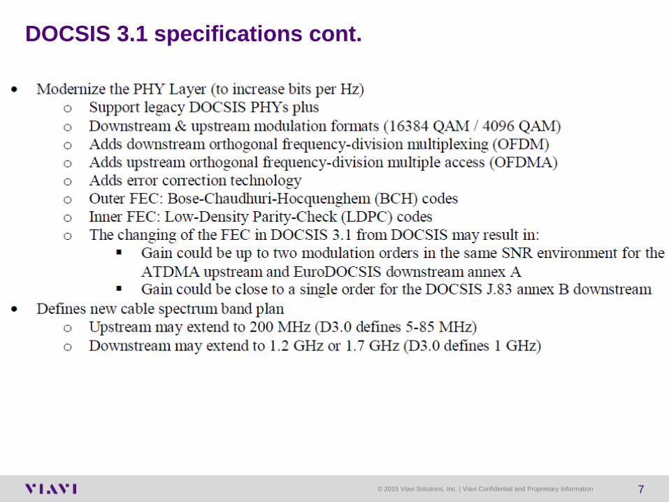
DOCSIS 3.1 specifications cont.
Web BrowsingE-mail
Digital MusicVoIP
Digital Photos
Video on Demand
Video Mail
Online Gaming
Podcasting
Video Blogs
High Definition Video on Demand
All Video on Demand Unicast per Subscriber
Meg
abits
per
Sec
ond
200
100
300
400
500
600
700
800
900
1000
Time
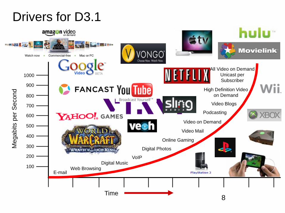
Drivers for D3.1 – Other than Verizon & AT&T!
8

© 2015 Viavi Solutions, Inc. | Viavi Confidential and Proprietary Information 9
Increased demand for BandwidthAdding bandwidth through two different ways
▫ Increasing Capacity by adding Megahertz – plant extensions▫ Increasing efficiency by more bits/Hz – OFDM & LDPC ▫ Or both
Source: Jeff Finklestein, CED webinar 11/2013

© 2015 Viavi Solutions, Inc. | Viavi Confidential and Proprietary Information 10
D3.1 Hurdles
Clear large chunks of spectrum for OFDM carriersConverting to all digital carriers, eliminating analogs. Completely new standards with new requirementsNew Tools for testing and system monitoringMid splits and Frequency extensionsMoCA interference if extending downstream to 1.2 GHzTraining

© 2015 Viavi Solutions, Inc. | Viavi Confidential and Proprietary Information 11
Increase spectral efficiency (more bits / hertz) Increase speeds to10GBs downstream and 1GBs
upstream Adapts to different spectrum and plant conditionsEasy migration from current version of DOCSISOperates on existing HFC systems
Goals of 3.1

© 2015 Viavi Solutions, Inc. | Viavi Confidential and Proprietary Information 12
Expanded BandwidthAdvanced ModulationBetter Error CorrectionCo Existence with legacy DOCSISPNM ToolsEnergy ManagementEliminates 6 and 8 MHz channel standardsNA and Europe now same standard
Backward compatibility with older versions of DOCSIS
D 3.1 Key Features

© 2015 Viavi Solutions, Inc. | Viavi Confidential and Proprietary Information 13
DS Extensions
• 1.2GHZ• DOCSIS 3.1 supports plant expansions to 1.2GHz. The
D3.1 CM & CMTS must support 1.2GHz• 1.794 GHz
• DOCSIS 3.1 support for 1.7GHz is optional for the CM & CMTS. be supported in a later version.
US Extensions
• 85MHz QAM or OFDM• DOCSIS 3.1 supports 85 MHz upstream just like D3.0
• 117MHz – for OFDM• DOCSIS 3.1 adds additional support for 117 MHz return
• 204MHz – for OFDM• DOCSIS 3.1 adds optional support for a 204MHz return
Frequency Extensions
Source: Cable Labs, DOCSIS 3.1 specification
© 2015 Viavi Solutions, Inc. | Viavi Confidential and Proprietary Information 14
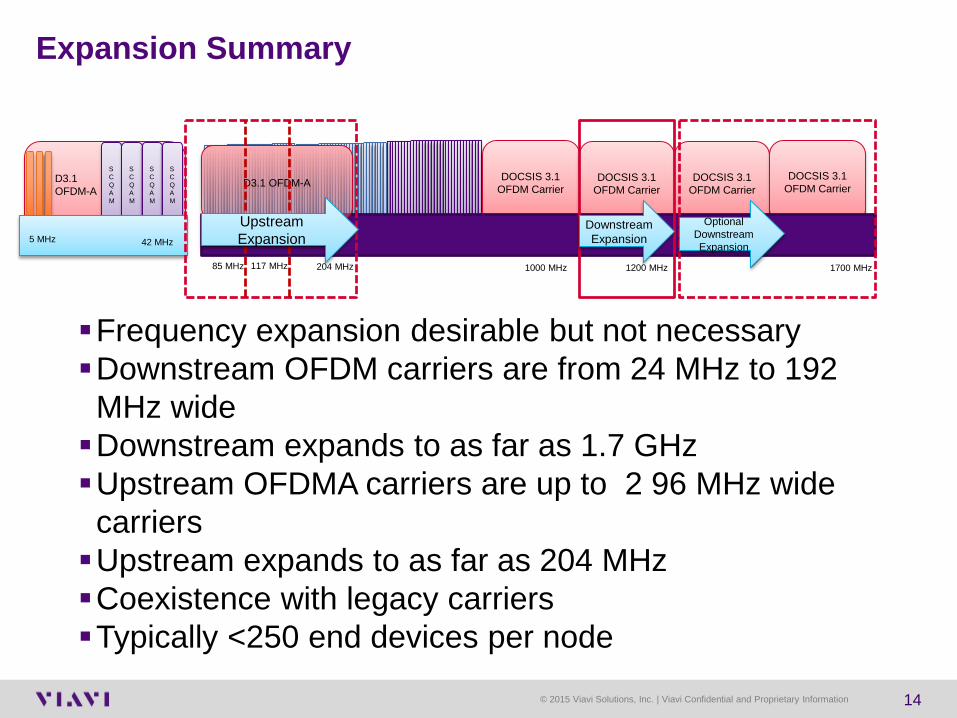
Expansion Summary
Frequency expansion desirable but not necessaryDownstream OFDM carriers are from 24 MHz to 192
MHz wideDownstream expands to as far as 1.7 GHzUpstream OFDMA carriers are up to 2 96 MHz wide
carriersUpstream expands to as far as 204 MHzCoexistence with legacy carriersTypically <250 end devices per node
SC QAM
SC QAM
SC QAM
SC QAM
5 MHz 42 MHz
D3.1 OFDM-A
DOCSIS 3.1 OFDM Carrier
DOCSIS 3.1 OFDM Carrier
DOCSIS 3.1 OFDM Carrier
DOCSIS 3.1 OFDM CarrierD3.1 OFDM-A
117 MHz 204 MHz 1000 MHz 1200 MHz 1700 MHz
Downstream Expansion
Optional Downstream Expansion
85 MHz
Upstream Expansion

© 2015 Viavi Solutions, Inc. | Viavi Confidential and Proprietary Information 15
D3.1 modems transmit up to 65 dBmV ▫ Home splitter isolation
TV IF 41 – 47 MHz▫ Tuner RF isolation
FM band ingress in the return pathSignal egress in the aeronautical band from the upstream
carriersDownstream OOB STB carriersUpstream Tilt and Equalization
Some Mid Split Issues to ponder

© 2015 Viavi Solutions, Inc. | Viavi Confidential and Proprietary Information 16
DOCSIS 3.0 / 3.1 Speeds and Frequencies
© 2015 Viavi Solutions, Inc. | Viavi Confidential and Proprietary Information 17
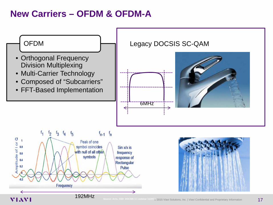
New Carriers – OFDM & OFDM-A
• Orthogonal Frequency Division Multiplexing
• Multi-Carrier Technology• Composed of “Subcarriers”• FFT-Based Implementation
OFDM
192MHz
6MHz
Legacy DOCSIS SC-QAM
Source: Arris, CED DOCSIS 3.1 webinar 11/2013
© 2015 Viavi Solutions, Inc. | Viavi Confidential and Proprietary Information 18
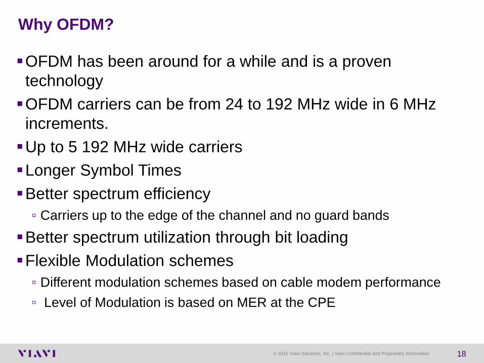
OFDM has been around for a while and is a proven technologyOFDM carriers can be from 24 to 192 MHz wide in 6 MHz
increments. Up to 5 192 MHz wide carriersLonger Symbol TimesBetter spectrum efficiency
▫ Carriers up to the edge of the channel and no guard bandsBetter spectrum utilization through bit loadingFlexible Modulation schemes
▫ Different modulation schemes based on cable modem performance▫ Level of Modulation is based on MER at the CPE
Why OFDM?

© 2015 Viavi Solutions, Inc. | Viavi Confidential and Proprietary Information 19
OFDM uses individual narrowband sub-carriers Sub carriers can be spaced at either 25 or 50 KHz in the downstream.
Or there could be as many as 8000 sub-carriers spaced at 25 KHz each within a 192 MHz wide downstream carrier. For even greater spectral efficiency, these subcarriers actually overlap
in spectrum. Each sub carrier can be turned off where there are interference issues
or legacy carriers are present. Each sub carrier has it’s own modulation levelGuard bands are eliminated therefore we gain bandwidth and can
transmit more bits per hertz. The carriers are distinguishable from each other because they are
mathematically orthogonal, meaning non-interfering. Sub carrier frequencies are chosen with the exact minimum spacing
that make them orthogonal.
OFDMOrthogonal Frequency Division Multiplexing

20© 2016 Viavi Solutions Inc.www.viavisolutions.com
Instantaneous Inverse Fast Fourier Transform
• A rectangular pulse in terms of time transforms into a 𝑆𝑆𝑆𝑆𝑆𝑆 𝑋𝑋𝑋𝑋
carrier in the frequency domain
• The 𝑆𝑆𝑆𝑆𝑆𝑆 𝑋𝑋𝑋𝑋
carrier has regularly spaced nulls in the frequency domain

21© 2016 Viavi Solutions Inc.www.viavisolutions.com
OFDM
Blue – 1 cycle per time period Green – 2 cycles per time periodRed - 3 cycles per time period Sub carrier spacing is
Equal to 1/TFFT
© 2015 Viavi Solutions, Inc. | Viavi Confidential and Proprietary Information 22
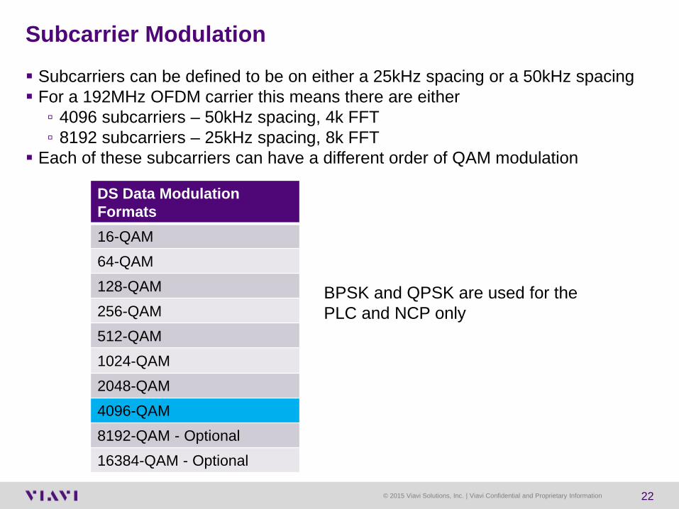
Subcarrier Modulation Subcarriers can be defined to be on either a 25kHz spacing or a 50kHz spacing For a 192MHz OFDM carrier this means there are either
▫ 4096 subcarriers – 50kHz spacing, 4k FFT▫ 8192 subcarriers – 25kHz spacing, 8k FFT
Each of these subcarriers can have a different order of QAM modulation
DS Data ModulationFormats16-QAM64-QAM128-QAM256-QAM512-QAM1024-QAM2048-QAM4096-QAM8192-QAM - Optional16384-QAM - Optional
BPSK and QPSK are used for the PLC and NCP only
24© 2016 Viavi Solutions Inc.www.viavisolutions.com
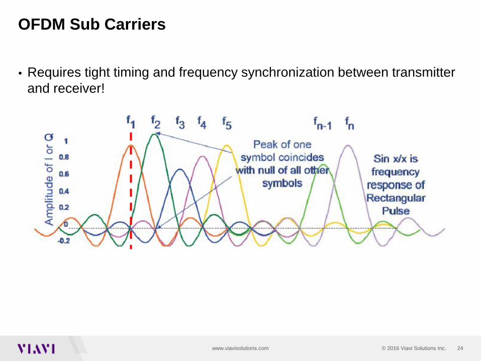
OFDM Sub Carriers
• Requires tight timing and frequency synchronization between transmitter and receiver!

© 2015 Viavi Solutions, Inc. | Viavi Confidential and Proprietary Information 25
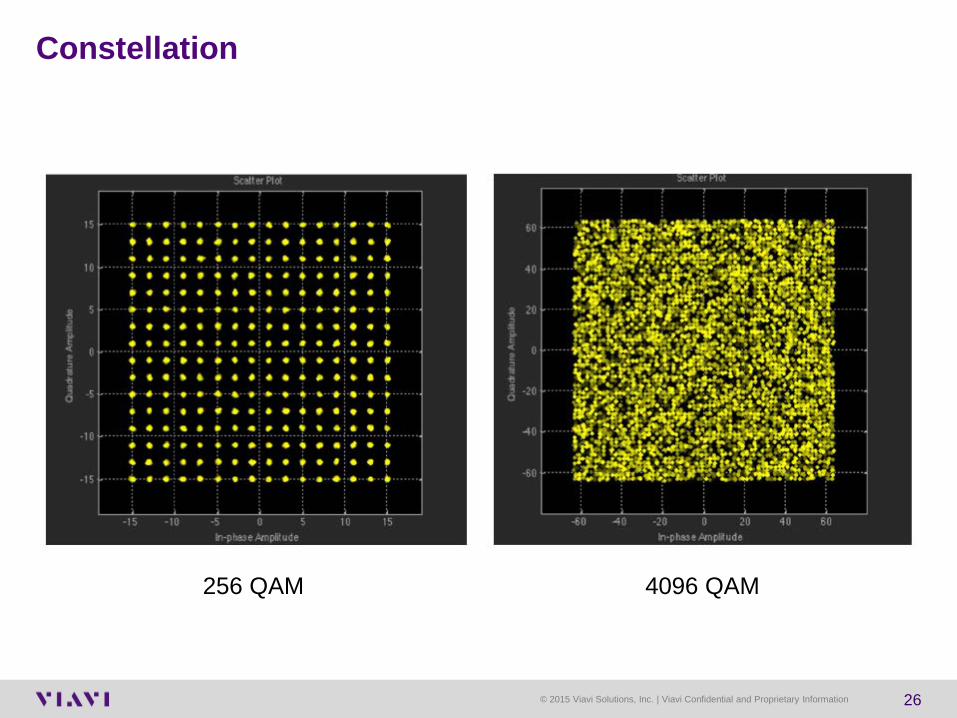
Simply means that different levels of QAM can be assigned to individual sub carriers.Higher orders of QAM carry more bits/hertz
▫ 256 QAM is 8 bits/symbol▫ 4096 QAM is 12 bits/symbol
Different Bit Loading with different Modulation ProfilesUse higher order of QAM with better plant performance
Advantages - Variable Bit Loading
© 2015 Viavi Solutions, Inc. | Viavi Confidential and Proprietary Information 26
Constellation
256 QAM 4096 QAM
27© 2016 Viavi Solutions Inc.www.viavisolutions.com
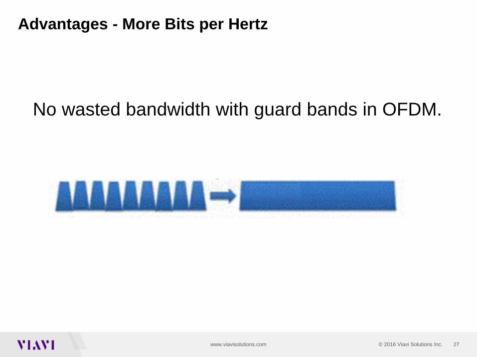
Advantages - More Bits per Hertz
No wasted bandwidth with guard bands in OFDM.
28© 2016 Viavi Solutions Inc.www.viavisolutions.com
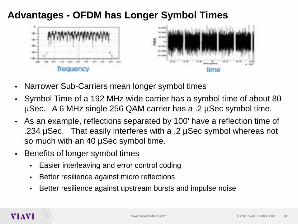
• Narrower Sub-Carriers mean longer symbol times• Symbol Time of a 192 MHz wide carrier has a symbol time of about 80
µSec. A 6 MHz single 256 QAM carrier has a .2 µSec symbol time.• As an example, reflections separated by 100’ have a reflection time of
.234 µSec. That easily interferes with a .2 µSec symbol whereas not so much with an 40 µSec symbol time.
• Benefits of longer symbol times• Easier interleaving and error control coding• Better resilience against micro reflections• Better resilience against upstream bursts and impulse noise
Advantages - OFDM has Longer Symbol Times

© 2015 Viavi Solutions, Inc. | Viavi Confidential and Proprietary Information 29
Modulation – SC QAM
6MHz
• Dedicated 6MHz Channels (8MHz in EMEA) • Each Frequency behaves independently• Symbols happen sequentially within the channel• Modulation is optimized for the worst part of the plant• Each symbol is about 2 µSec in duration
CH 78
CH 79
CH 81
CH 80
CH 82
CH 83
CH 85
CH 84
48MHz
Time
V I A V I
One Symbol, 8 bits for 256 QAM
Frequency
Time50 MHz
860 MHz

© 2015 Viavi Solutions, Inc. | Viavi Confidential and Proprietary Information 30
OFDM – Orthogonal Frequency Domain MultiplexingSubcarriers and symbols
192MHz
• OFDM uses 25kHz or 50kHz subcarriers spread across the entire bandwidth of the carrier• In the above example, a 192MHz OFDM Carrier w/ 25kHz spacing, there are 8000 subcarriers • All subcarriers are time synchronized across the entire bandwidth of the carrier• Each subcarrier has its own modulation type (64 QAM, 256 QAM, 1024 QAM, 4096 QAM etc)• Demodulation is FFT (Fast Fourier Transform) based so time synch is critical• Codewords are spread across multiple subcarriers and multiple time slots (symbols)
25 kHz
Time
One symbol is up to ≈ 98,000 bits CP-Time between symbols
V
I
A
V
I
SO
L
U
T
IO
N
S
192 MHz1 Symbol
Cyclic Prefix Time
One Symbol 40 µSeconds

31© 2016 Viavi Solutions Inc.www.viavisolutions.com
Exclusions
• OFDM allows for the ability to exclude specific subcarriers. • At least 2 MHz of data spectrum between Exclusion Bands• Exclusion bands must be at least 1 MHz wide and less than 20% of the OFDM
carrier spectrum.
Time

32© 2016 Viavi Solutions Inc.www.viavisolutions.com
DOCSIS 3.1 Downstream Profiles
Tailor profiles to account for SNR differences in the plant
Worst – (mostly 256 QAM)Avg. – (mostly 1024 QAM)Better (mostly 2048 QAM)Best (mostly 4096 QAM)
Worst Avg. Better Best
Some CM’s can do better than others – so let them
Net capacity is higher than the “least common denominator”
• Profiles maximize traffic capabilities over varying plant conditions• Modifies the bit loading on each sub-carrier• Maximizes data efficiency

33© 2016 Viavi Solutions Inc.www.viavisolutions.com
Required Minimum SNR for different orders of QAM
Order of QAM Minimum MER Threshold
SNR Range
4096 36 dB >382048 33 dB 35-38 dB1024 30 dB 32-35 dB512 27 dB 29-32 dB256 24 dB 15-29 dB
34© 2016 Viavi Solutions Inc.www.viavisolutions.com
Downstream Profiles
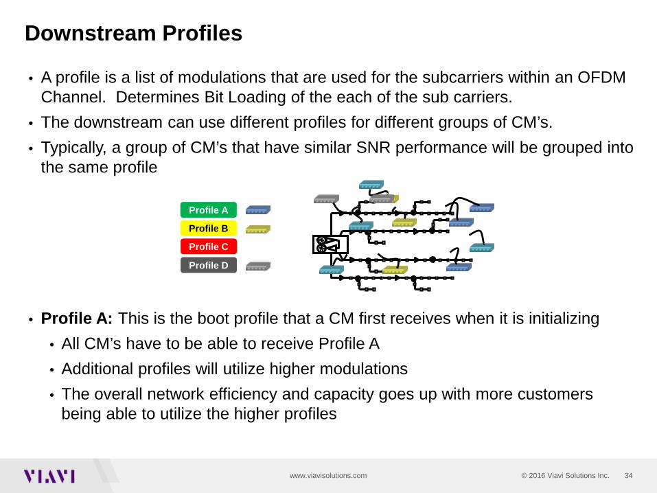
• A profile is a list of modulations that are used for the subcarriers within an OFDM Channel. Determines Bit Loading of the each of the sub carriers.
• The downstream can use different profiles for different groups of CM’s.• Typically, a group of CM’s that have similar SNR performance will be grouped into
the same profile
• Profile A: This is the boot profile that a CM first receives when it is initializing• All CM’s have to be able to receive Profile A• Additional profiles will utilize higher modulations• The overall network efficiency and capacity goes up with more customers
being able to utilize the higher profiles
Profile A
Profile B
Profile C
Profile D
35© 2016 Viavi Solutions Inc.www.viavisolutions.com
• Not addressed by the D3.1 specificationsStatic• Operators configure Profiles in the CMTS
• Manually done by known plant and modem performance • Duplicate Profiles from other markets• Helper functions from CMTS manufacturers or 3rd party vendors
Dynamic• As PNM data is analyzed and Profiles are changed based on CM
performance• Profiles vary slowly, not intended to handle short term events
• If a single modem has a problem, then that modem moves to a lower Profile
• If many modems have a problem, the profile is changed
How are Profiles Established?

36© 2016 Viavi Solutions Inc.www.viavisolutions.com
Modulation Profiles – basic concept
For simplicity sake, let’s assume that the profiles use the same modulation for all subcarriers.
256 QAM1024 QAM2048 QAM4096 QAM
Legend
Time
Profile AProfile BProfile CProfile D
Simplified for conceptual purposes
Freq

37© 2016 Viavi Solutions Inc.www.viavisolutions.com
Profiles – realistic concept
OFDM allows for the ability to exclude specific subcarriers. It also allows each profile to vary the modulation on each subcarrier.This allows the ability to optimize the overall carrier performance. Each profile have the same exclusions.
256 QAM1024 QAM2048 QAM4096 QAM
Legend
Time
Profile AProfile C Profile BProfile D
Simplified for conceptual purposes
38© 2016 Viavi Solutions Inc.www.viavisolutions.com
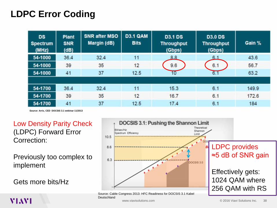
LDPC Error Coding
LDPC provides ≈5 dB of SNR gain
Effectively gets: 1024 QAM where 256 QAM with RS
Low Density Parity Check (LDPC) Forward Error Correction:
Previously too complex to implement
Gets more bits/HzSource: Cable Congress 2013: HFC Readiness for DOCSIS 3.1 KabelDeutschland
Source: Arris, CED DOCSIS 3.1 webinar 11/2013

39© 2016 Viavi Solutions Inc.www.viavisolutions.com
• Instead of adding bits for RS, now there are codes at the end of a number of bits with position of the 1s in the row.
Forward Error Correction LDPC

40© 2016 Viavi Solutions Inc.www.viavisolutions.com
Error Correction – LDPCLow Density Parity Check
• LPDC does add to the bandwidth
In the downstream, LDPC uses 16,200 bit codewords.

© 2015 Viavi Solutions, Inc. | Viavi Confidential and Proprietary Information 41
DOCSIS 3.1 Spectrum and Different Sub Carrier Types

42© 2016 Viavi Solutions Inc.www.viavisolutions.com
Sub Carrier Parameters
© 2015 Viavi Solutions, Inc. | Viavi Confidential and Proprietary Information 43
Physical Link Channel (PLC)
PLCs are sub carriers known to the cable modem and carry information about the downstream Physical Layer.▫ Timestamp ▫ Energy management ▫ Trigger message for synchronizing an event between the CMTS and
CM. ▫ Message channel for bringing new CMs on line.
Either 8 with 50 KHz or 16 with 25 KHz sub carriers wide and total 400 KHz within the OFDM carrierWith surrounding Continuous Pilots a total of 6 MHz wide Placed in within the carrier, but not necessarily at the center Preamble is BPSK and the PLC itself is 16 QAM for robustness No exclusions in PLC bandwidthWithout the PLC aquistion, the modem cannot decode data from the
CMTS
© 2015 Viavi Solutions, Inc. | Viavi Confidential and Proprietary Information 44
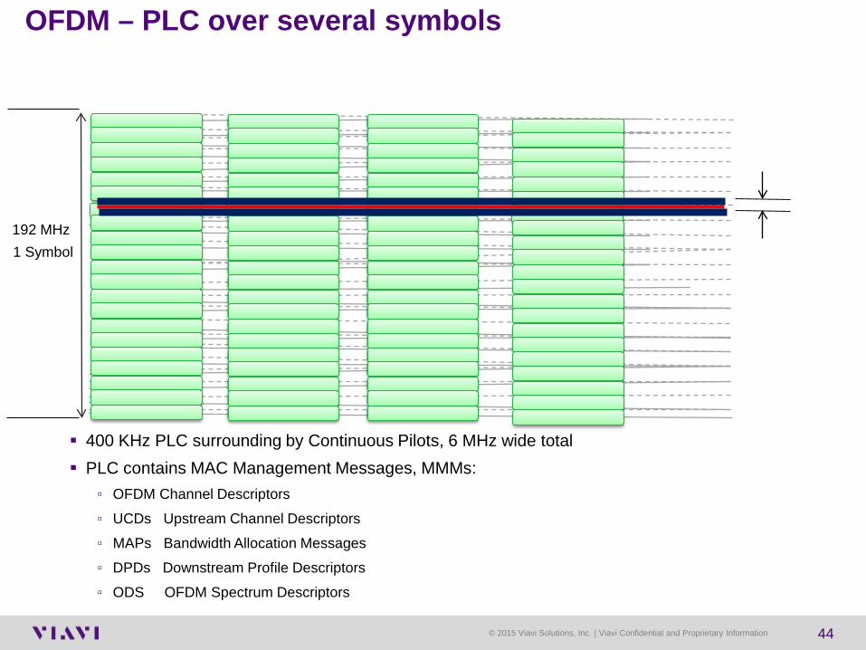
400 KHz PLC surrounding by Continuous Pilots, 6 MHz wide total PLC contains MAC Management Messages, MMMs:
▫ OFDM Channel Descriptors▫ UCDs Upstream Channel Descriptors▫ MAPs Bandwidth Allocation Messages ▫ DPDs Downstream Profile Descriptors▫ ODS OFDM Spectrum Descriptors
OFDM – PLC over several symbols
192MHz
25 kHz
Time
One symbol is up to ≈ 98,000 bits CP-Time between symbols
192 MHz1 Symbol

45© 2016 Viavi Solutions Inc.www.viavisolutions.com
NCP – Next Codeword Pointer
When data codewords are mapped to subcarriers within a symbol, a pointer is needed to identify where a data codewords start. The Main task of the NCP message block is to provide a reference to
the appropriate profile and a start pointer for codewords. The NCP MUST use one of three modulation formats
NCP Modulation
# of Subcarriers
QPSK 2416-QAM 1264-QAM 8 It is critical that the NCP does
not have uncorrectable code word errors.
46© 2016 Viavi Solutions Inc.www.viavisolutions.com
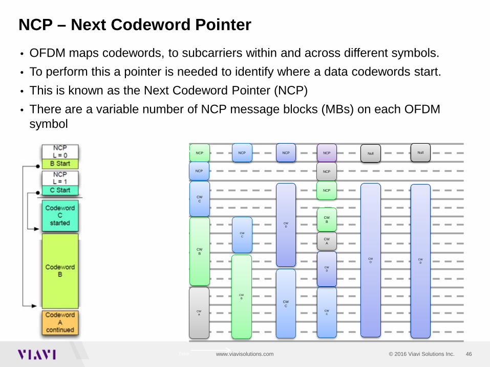
• OFDM maps codewords, to subcarriers within and across different symbols.• To perform this a pointer is needed to identify where a data codewords start.• This is known as the Next Codeword Pointer (NCP)• There are a variable number of NCP message blocks (MBs) on each OFDM
symbol
NCP – Next Codeword Pointer
Time
Freq
CW A
CWB
CWC
CWD
CWC
NCP
NCP
NCP NCP
CWD
NCP
NCP
CW A
CW B
CWC
CWD
Null
CWD
Null
CW C
NCP
CWB
47© 2016 Viavi Solutions Inc.www.viavisolutions.com
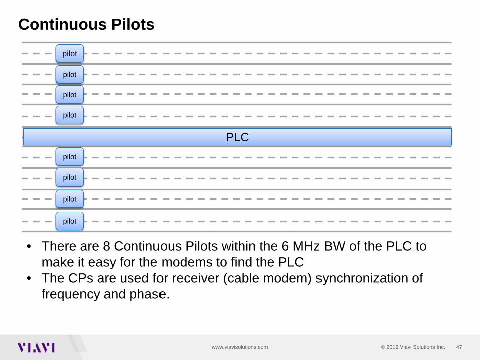
Continuous Pilots
Time
PLC
pilot
pilot
pilot
pilot
pilot
pilot
pilot
pilot
• There are 8 Continuous Pilots within the 6 MHz BW of the PLC to make it easy for the modems to find the PLC
• The CPs are used for receiver (cable modem) synchronization of frequency and phase.

48© 2016 Viavi Solutions Inc.www.viavisolutions.com
Continuous PilotsPLC Surrounded byContinuous Pilots
49© 2016 Viavi Solutions Inc.www.viavisolutions.com
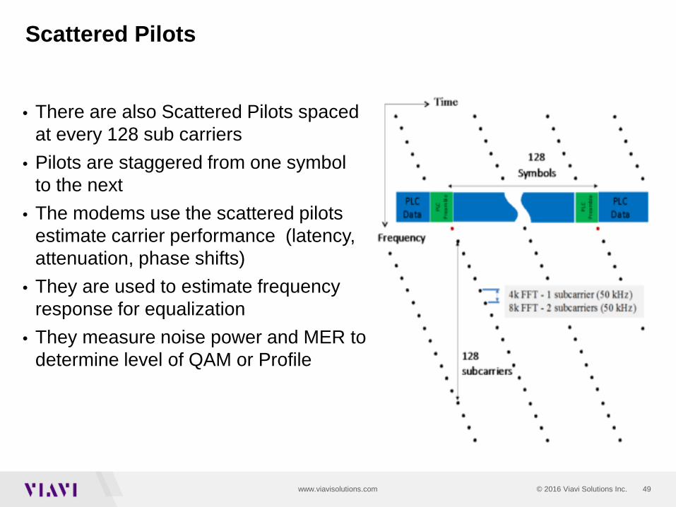
• There are also Scattered Pilots spaced at every 128 sub carriers
• Pilots are staggered from one symbol to the next
• The modems use the scattered pilots estimate carrier performance (latency, attenuation, phase shifts)
• They are used to estimate frequency response for equalization
• They measure noise power and MER to determine level of QAM or Profile
Scattered Pilots

50© 2016 Viavi Solutions Inc.www.viavisolutions.com
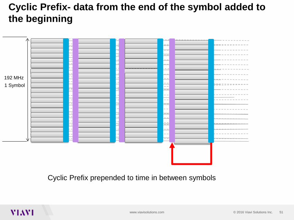
• The data from the end of each symbol is added to the time period of the beginning of the symbol.
• The time duration of the CP should longer than the time of the longest significant reflection.
• The CP does add overhead to the OFDM carriers
Cyclic Prefix
51© 2016 Viavi Solutions Inc.www.viavisolutions.com
Cyclic Prefix- data from the end of the symbol added to the beginning
192MHz
25 kHz
Time
One symbol is up to ≈ 98,000 bits CP-Time between symbols
192 MHz1 Symbol
Cyclic Prefix prepended to time in between symbols

52© 2016 Viavi Solutions Inc.www.viavisolutions.com
Windowing
• Simply put it is a raised cosine filter that determines how the carrier rolls off at the beginning and end of the carrier. Also at the beginning and end of exclusions
• The roll off must be integrated within the duration of the CP• Windowing provides resilience against narrow band interference.
Source Rhode and Schwartz
© 2015 Viavi Solutions, Inc. | Viavi Confidential and Proprietary Information 53
Active Queue Management
Increases operator’s ability to improve customer’s QoE by moving packets more efficiency. Boosts responsiveness for gamers and other web
applications by reducing latencyActively manages data passing through the network and
optimizes cable modem buffer usage.

54© 2016 Viavi Solutions Inc.www.viavisolutions.com
OFDM and Adaptive Equalization
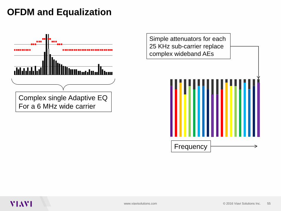
• Another major advantage of OFDM is the ability to adapt to degraded conditions such as micro-reflections without the need for complex adaptive equalization.
• OFDM uses a very narrow bandwidth subcarrier typically experiences what is known as “flat fading” when micro-reflections affect channel response.
• This is in contrast to a 6 MHz wide QAM carrier and is susceptible to amplitude ripple (standing waves) across the entire bandwidth.
• Each OFDM subcarrier “sees” a tiny portion of the ripple, that affects only the amplitude of the narrow subcarrier.
• Since the subcarriers are so narrow, we can simply attenuate individual sub carriers accordingly as opposed to a complex AE
55© 2016 Viavi Solutions Inc.www.viavisolutions.com
OFDM and Equalization
Complex single Adaptive EQFor a 6 MHz wide carrier
Simple attenuators for each 25 KHz sub-carrier replace complex wideband AEs
Frequency

56© 2016 Viavi Solutions Inc.www.viavisolutions.com
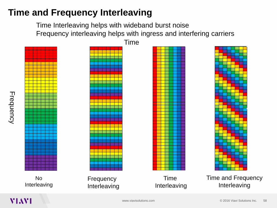
• Frequency Interleaving minimizes the effects of narrowband interference
• Errors are distributed over multiple sub carriers• Performed at sub carrier level
• Time Interleaving minimizes the effects of impulse noise• Errors on a single symbol are distributed on multiple OFDM
symbols• Performed at the sub carrier level
Time and Frequency Interleaving

57© 2016 Viavi Solutions Inc.www.viavisolutions.com
Time Interleaving
A1 A2 A3 A4 A5 A6 A7 A8
B1 B2 B3 B4 B5 B6 B7 B8
C1 C2 C3 C4 C5 C6 C7 C8
D1 D2 D3 D4 D5 D6 D7 D8
A1 A2 A3 A4 A5 A6 A7 A8
A1 B1 C1 D1 A2 B2 C2 D2
T
Non-Interleaved
Interleaved
T
58© 2016 Viavi Solutions Inc.www.viavisolutions.com
Time and Frequency Interleaving
No Interleaving
Frequency Interleaving
Time Interleaving
Time and FrequencyInterleaving
Time
Frequency
Time Interleaving helps with wideband burst noise Frequency interleaving helps with ingress and interfering carriers

59© 2016 Viavi Solutions Inc.www.viavisolutions.com
• OFDM Modulation• System optimized for simplicity and efficiency• Frequency agility allows for exclusions due to interferers
and legacy channels• Ideal modulation scheme that provides maximum data
efficiency • Multi-Profile architecture to match CM MER distribution• Improved error correction, LPDC, provides higher orders
of modulation with the same CNR
Downstream Conclusions

60© 2016 Viavi Solutions Inc.www.viavisolutions.com 60© 2016 Viavi Solutions Inc.www.viavisolutions.com
Upstream OFDMA

© 2015 Viavi Solutions, Inc. | Viavi Confidential and Proprietary Information 61
Upstream OFDMA Parameters

© 2015 Viavi Solutions, Inc. | Viavi Confidential and Proprietary Information 62
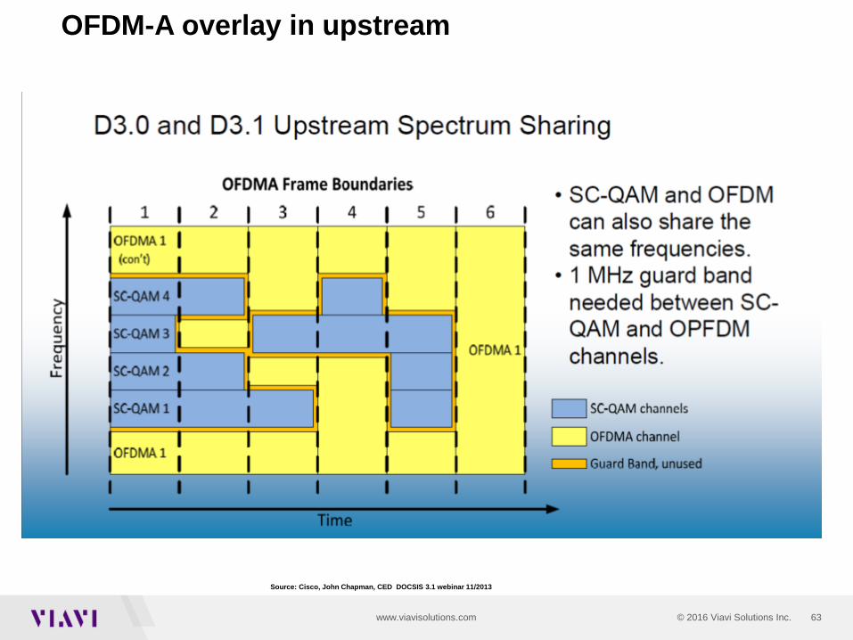
Upstream Carriers
Remember that in the upstream the carriers will be wider than the normal 6 MHz bandwidth and that power levels will need to be modified to reflect the change in BW.
63© 2016 Viavi Solutions Inc.www.viavisolutions.com
OFDM-A overlay in upstream
Source: Cisco, John Chapman, CED DOCSIS 3.1 webinar 11/2013

64© 2016 Viavi Solutions Inc.www.viavisolutions.com
OFDM-A – Frames and MiniSlots
96MHz
• Symbols are grouped into frames – configurable from 6-32 symbols• Subcarriers are grouped into mini-slots
• Must be either 8 or 16 subcarriers per mini-slot• Subcarriers can be bit-loaded from QPSK to 4096 QAM
25 kHz
Time
T sym
Frame 1 Frame 2 Frame .. Frame N
Mini Slot 1
Mini Slot 2
Mini Slot …
65© 2016 Viavi Solutions Inc.www.viavisolutions.com
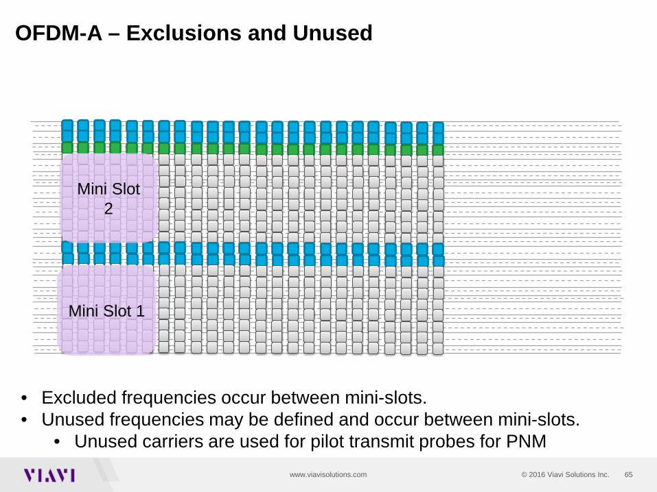
OFDM-A – Exclusions and Unused
96MHz
• Excluded frequencies occur between mini-slots. • Unused frequencies may be defined and occur between mini-slots.
• Unused carriers are used for pilot transmit probes for PNM
25 kHz
Time
Mini Slot 1
Mini Slot 2
ExcludedUnusedUsed

66© 2016 Viavi Solutions Inc.www.viavisolutions.com
• Different modems have different MERs at the CMTS• In D3, the modem with the lowest MER normally dictates the highest level of
upstream QAM or the highest speed capability• D3.1 will provide multiple modulation profiles so that each modem will be able to
transmit at it’s highest QAM modulation profile• Profiles are assigned at registration• Profiles can be dynamically changed using UCD change procedure• Operators can tailor profiles to meet plant conditions
• Profiles are not unique to each modem
Upstream Multiple Modulation Profiles

67© 2016 Viavi Solutions Inc.www.viavisolutions.com
Upstream Pilots
• Upstream Pilots are subcarriers that do not carry data. • Instead a pilot subcarrier encodes a pre-defined BPSK symbol
known to the CMTS.• Pilots are used by the CMTS receiver to adapt to channel
conditions and frequency offsets.• Complementary pilots are subcarriers that carry data, but with a
lower modulation order than other data subcarriers.• The CMTS may use the complementary pilots to enhance its
processing and accuracy

© 2015 Viavi Solutions, Inc. | Viavi Confidential and Proprietary Information 68
Upstream Pre Equalization
One equalization coefficient per sub-carrierCMTS evaluates and determines EQ adjustmentsCMTS sends EQ adjustments to the cable modem Increases the accuracy of PNM distance measurements from
several feet to a few inches.

© 2015 Viavi Solutions, Inc. | Viavi Confidential and Proprietary Information 69
Upstream Conclusions
OFDMA is:▫ Robust: Profiles fit system performance Interleaving LPDCMinislots and Framing
▫ Flexible Different levels of QAM and bondingWorks with legacy upstreams Exclusions Transmits at the same frequencies as legacy carriers during time
periods when they aren’t being used.▫ Up to 2 96 MHz wide carriers with up to 200MHz upstream bandwidth

70© 2016 Viavi Solutions Inc.www.viavisolutions.com 70© 2016 Viavi Solutions Inc.www.viavisolutions.com
Testing what matters in D3.1

71© 2016 Viavi Solutions Inc.www.viavisolutions.com
• CMs and CMTSs were not designed to be test equipment but we did get……
• Spectrum Analysis at both the CM and CMTS• Pre EQ coefficients that aid in troubleshooting (PNM tools)
• In D 3.1 measurements from the CMTS and CMs are specified.
DOCSIS 3.0 Testing at the CM and CMTS
72© 2016 Viavi Solutions Inc.www.viavisolutions.com
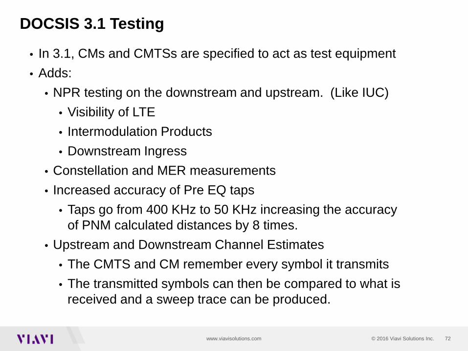
• In 3.1, CMs and CMTSs are specified to act as test equipment• Adds:
• NPR testing on the downstream and upstream. (Like IUC)• Visibility of LTE• Intermodulation Products• Downstream Ingress
• Constellation and MER measurements• Increased accuracy of Pre EQ taps
• Taps go from 400 KHz to 50 KHz increasing the accuracy of PNM calculated distances by 8 times.
• Upstream and Downstream Channel Estimates• The CMTS and CM remember every symbol it transmits• The transmitted symbols can then be compared to what is
received and a sweep trace can be produced.
DOCSIS 3.1 Testing

73© 2016 Viavi Solutions Inc.www.viavisolutions.com
Remote PNM Diagnostic Tool
Please note that in this example, the existing four-port tap faceplate displayed in the white area is replaced by a new faceplate that has the existing tap structure in white but also the new forward and reverse test taps as displayed in the yellow area. Spliced in each leg of a node or within the housing.itself.
Source: Jack Moran
© 2015 Viavi Solutions, Inc. | Viavi Confidential and Proprietary Information 74
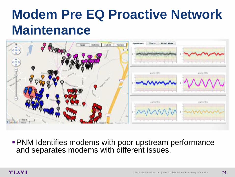
Modem Pre EQ Proactive Network Maintenance
PNM Identifies modems with poor upstream performance and separates modems with different issues.
© 2015 Viavi Solutions, Inc. | Viavi Confidential and Proprietary Information 75
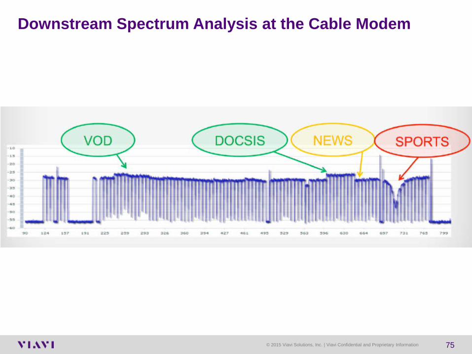
Downstream Spectrum Analysis at the Cable Modem
© 2015 Viavi Solutions, Inc. | Viavi Confidential and Proprietary Information 76
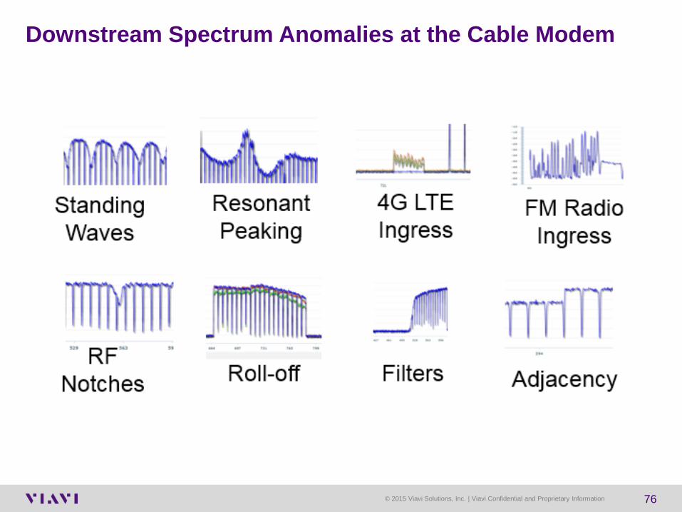
Downstream Spectrum Anomalies at the Cable Modem

78© 2016 Viavi Solutions Inc.www.viavisolutions.com
Notch Filter Testing at the CMTS (NPR)
Uses Exclusion Bands to test for upstream dynamic range
79© 2016 Viavi Solutions Inc.www.viavisolutions.com
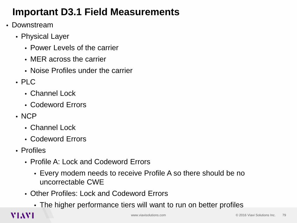
Important D3.1 Field Measurements• Downstream
• Physical Layer• Power Levels of the carrier• MER across the carrier• Noise Profiles under the carrier
• PLC • Channel Lock• Codeword Errors
• NCP • Channel Lock• Codeword Errors
• Profiles• Profile A: Lock and Codeword Errors
• Every modem needs to receive Profile A so there should be no uncorrectable CWE
• Other Profiles: Lock and Codeword Errors• The higher performance tiers will want to run on better profiles
80© 2016 Viavi Solutions Inc.www.viavisolutions.com
What is important to test and measure on DOCSIS 3.1
• Service Layer• Registration and Bonding
• Did it register and come on line as 3.1?• Are the 3.1 OFDM carriers active and bonded?
• Upstream• Carrier Power levels• Bonding – Am I getting the bonding I expected• ICFR – In Channel Frequency Response of each carrier
81© 2016 Viavi Solutions Inc.www.viavisolutions.com
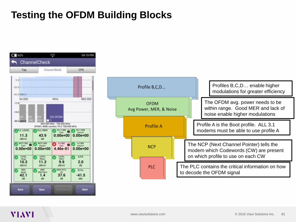
Testing the OFDM Building Blocks
The PLC contains the critical information on how to decode the OFDM signal
The NCP (Next Channel Pointer) tells the modem which Codewords (CW) are present on which profile to use on each CW
Profile A is the Boot profile. ALL 3.1 modems must be able to use profile A
Profiles B,C,D… enable higher modulations for greater efficiency
The OFDM avg. power needs to be within range. Good MER and lack of noise enable higher modulations

83© 2016 Viavi Solutions Inc.www.viavisolutions.com
DOCSIS Codewords
• In our example, each code word consists of 128 RS symbols. 122 of those symbols carry data. The remaining 6 symbols are used for error correction.
-ITU-T J.83, Annex B states that the data is “…encoded using a (128,122) code over GF(128)…” which shows each RS codeword consists of 128 RS symbols (first number in first parentheses) and the number of data symbols per RS codeword is 122 (second number in first parentheses), leaving six symbols per RS codeword for error correction.
• DOCSIS RS FEC is configured for what is known as “t = 3,” which means that the 6 FEC can fix up to any three errored RS symbols in a RS codeword.

84© 2016 Viavi Solutions Inc.www.viavisolutions.com
DOCSIS Downstream Codewords
• In DOCSIS Reed Solomon FEC, 7 bits = 1 RS symbol, and 128 RS symbols = 1 RS codeword
7 bits = 1 RS symbol
In each RS codeword: 122 RS symbols = data symbols, 6 RS symbols = parity symbols
0 1 1 0 0 1 0
128 RS symbols = 1 RS codeword
RS symbol #1 RS symbol #2 RS symbol #3 RS symbol #4 RS symbol #127 RS symbol #128
Source Ron Hranac

85© 2016 Viavi Solutions Inc.www.viavisolutions.com
Codeword Errors
• What happens when there is, say, a burst of noise that causes a bit error or errors in one RS symbol?
• It doesn’t matter to the RS decoder if one bit in that RS symbol is errored or all seven bits are errored—the entire symbol is considered broken.
= good RS symbol
= errored RS symbol
= errored RS symbol
= errored RS symbol
Source Ron Hranac
86© 2016 Viavi Solutions Inc.www.viavisolutions.com
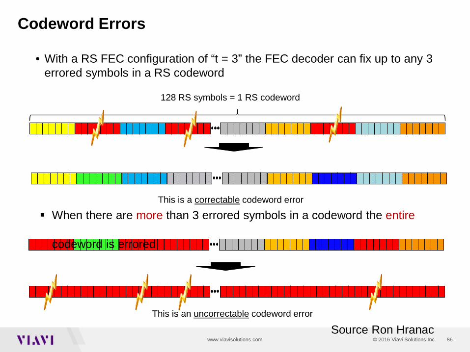
Codeword Errors
• With a RS FEC configuration of “t = 3” the FEC decoder can fix up to any 3 errored symbols in a RS codeword
128 RS symbols = 1 RS codeword
When there are more than 3 errored symbols in a codeword the entire
codeword is errored
This is a correctable codeword error
This is an uncorrectable codeword error
Source Ron Hranac
87© 2016 Viavi Solutions Inc.www.viavisolutions.com
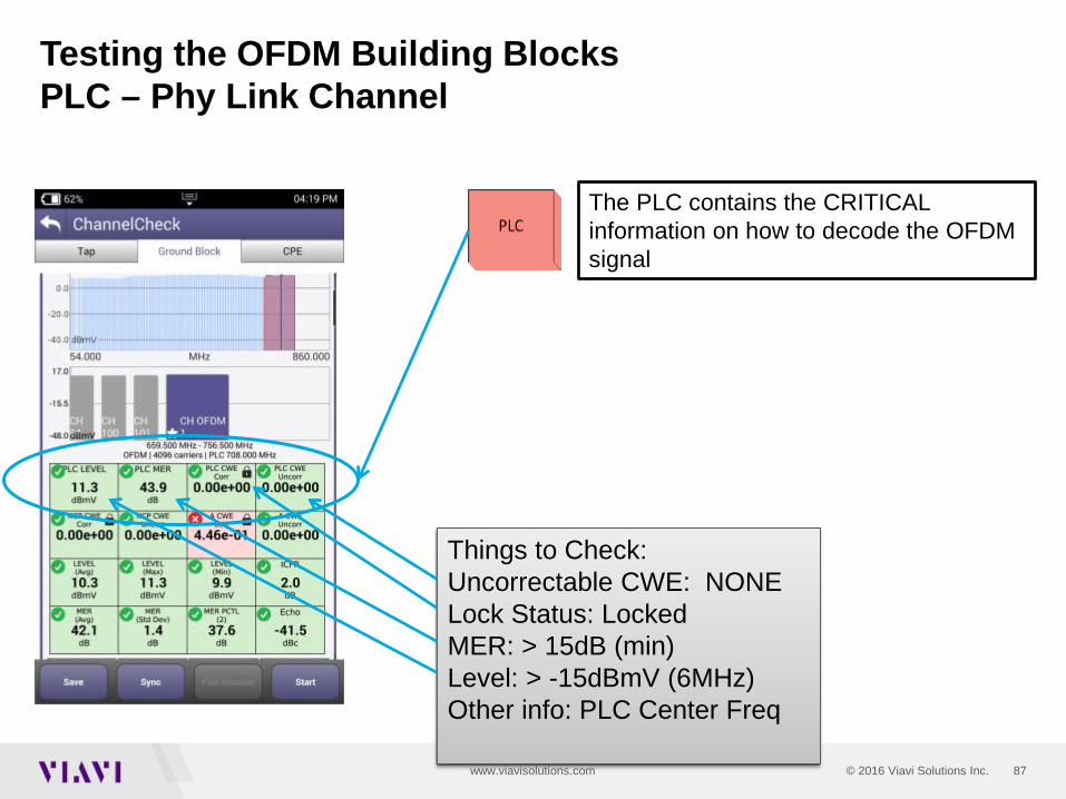
Testing the OFDM Building BlocksPLC – Phy Link Channel
Things to Check:Uncorrectable CWE: NONELock Status: LockedMER: > 15dB (min)Level: > -15dBmV (6MHz)Other info: PLC Center Freq
The PLC contains the CRITICAL information on how to decode the OFDM signal
88© 2016 Viavi Solutions Inc.www.viavisolutions.com
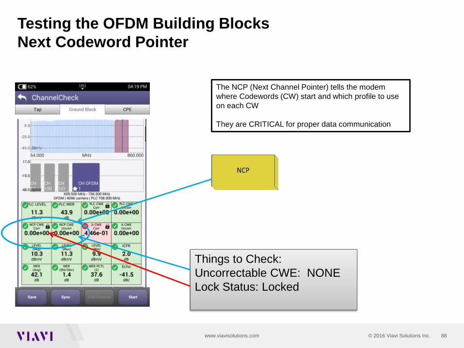
Testing the OFDM Building BlocksNext Codeword Pointer
The NCP (Next Channel Pointer) tells the modem where Codewords (CW) start and which profile to use on each CW
They are CRITICAL for proper data communication
Things to Check:Uncorrectable CWE: NONELock Status: Locked

89© 2016 Viavi Solutions Inc.www.viavisolutions.com
Testing the OFDM Building BlocksProfile A
Profile A is the Boot profile. ALL 3.1 modems must be able to use profile A
Things to Check:Uncorrectable CWE: NONELock Status: Locked
Profile is the cornerstone for a D3.1 modem to actually operate on the OFDM carrier. This is where the command and control, range and registration occurs.
In practice Profile A may be assigned lower mixed modulations like QAM 64/16 so every 3.1 modem can communicate. Lower modulation profiles can operate at lower MER/CNR and power levels.
If Profile A isn’t locked or has Uncorrectable. CWE the modem may roll back and use only SC-QAM’s in 3.0 mode

90© 2016 Viavi Solutions Inc.www.viavisolutions.com
How to set the level of a D3.1 OFDM carrier
DOCSIS 3.1 OFDM Carrier DOCSIS 3.1 OFDM Carrier
DOCSIS 3.1 OFDM carrier power levels should be measured and referenced in comparison to the power in a 6MHz carrier.
In a flat system, the average power of the OFDM, referenced to a 6MHz carrier should be set to the same power level as the adjacent QAM 256 carriers.
NOTE: The TOTAL power of the OFDM carrier is greatly different than the average power in a 6MHz bandwidth.
Total Power = Total Power PER Channel (6MHz) + 10log10(Channel Bandwidth).Where Channel Bandwidth would be overall OFDM Bandwidth/6MHz channel bandwidth = # of 6MHz Channelsfor a 96MHz wide OFDM carrier the TOTAL power will be 12.04dB higher for a 192 MHz wide OFDM carrier the TOTAL power will be 15.05dB higher
NOTE: DON’T USE THE TOTAL OFDM POWER to ADJUST CMTS OUTPUT POWER(This would be like using the total integrated power of 32 DOCSIS QAM carriers to set the level)
Single 6MHz channel power = 5 dBmVTotal Power(96MHz channel) = 5dBmV + 10log10(16) = 5 + 12.04 = 17.04dBmVThis is what some spectrum analyzers (like R&S FSW) show –
total power of 96MHz wide carrier: This is not referenced to a 6MHz carrier
SC-QAM
91© 2016 Viavi Solutions Inc.www.viavisolutions.com
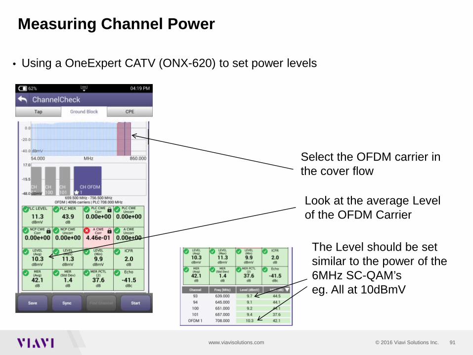
Measuring Channel Power
• Using a OneExpert CATV (ONX-620) to set power levels
Select the OFDM carrier in the cover flow
Look at the average Level of the OFDM Carrier
The Level should be set similar to the power of the 6MHz SC-QAM’seg. All at 10dBmV
92© 2016 Viavi Solutions Inc.www.viavisolutions.com
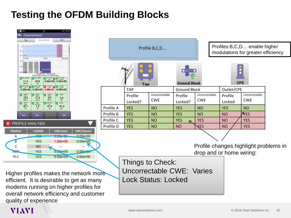
Testing the OFDM Building Blocks
Profiles B,C,D… enable higher modulations for greater efficiency
TAP Ground Block Outlet/CPEProfileLocked?
Uncorrectable
CWEProfileLocked?
Uncorrectable
CWEProfileLocked
Uncorrectable
CWE
Profile A YES NO YES NO YES NOProfile B YES NO YES NO NO YESProfile C YES NO YES YES NO YESProfile D YES NO NO YES NO YES
Profile changes highlight problems in drop and or home wiring:
Things to Check:Uncorrectable CWE: VariesLock Status: Locked
Higher profiles makes the network more efficient. It is desirable to get as many modems running on higher profiles for overall network efficiency and customer quality of experience

93© 2016 Viavi Solutions Inc.www.viavisolutions.com
Testing the OFDM Building BlocksCodeWord Error Expectations and Impact
Component Importance Code Word Error expectations and impact
PLC Critical Should have 0 Uncorrectable CWE otherwise OFDM may not work
NCP Critical Should have 0 Uncorrectable CWE otherwise OFDM may not work
Profile A Critical Uncorrectable CWE will cause poor QOE and possibly make the OFDM carrier unusable forcing data to regular QAM carriers instead of OFDM
Profile B,C,D High Uncorrectable CWE will affect bandwidth and overall QOE
The PLC contains the critical information on how to decode the OFDM signal
The NCP (Next Channel Pointer) tells the modem which Codewords (CW) are present on which profile to use on each CW
Profile A is the Boot profile. ALL 3.1 modems must be able to use profile A
Profiles B,C,D… enable higher modulations for greater efficiency
The OFDM avg. power needs to be within range. Good MER and lack of noise enable higher modulations
94© 2016 Viavi Solutions Inc.www.viavisolutions.com
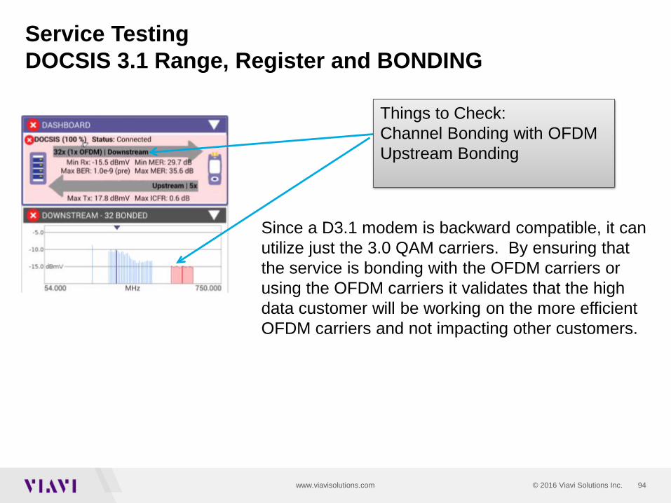
Service TestingDOCSIS 3.1 Range, Register and BONDING
Since a D3.1 modem is backward compatible, it can utilize just the 3.0 QAM carriers. By ensuring that the service is bonding with the OFDM carriers or using the OFDM carriers it validates that the high data customer will be working on the more efficient OFDM carriers and not impacting other customers.
Things to Check:Channel Bonding with OFDMUpstream Bonding

95© 2016 Viavi Solutions Inc.www.viavisolutions.com
DOCSIS 3.1 TestingSignal Testing and Troubleshooting
Unstable MER with drops below 30 means only the lower profiles running 256 QAM or lower will work
Stable MER better than 40dB means QAM 2048 and 4096 will work
Signal TestingLooking a the MER across the entire list of subcarriers is important in order to identify potential impairments that affect the ability to carry higher level profiles
Spectrum and Noise identify portions of the carrier where degradation may occur Profiles may need to adjust for this
In-Channel Response identifies roll-off and excessive ripple

96© 2016 Viavi Solutions Inc.www.viavisolutions.com
Service TestingThroughput DOCSIS 3.1 systems can provide 1Gb/s or
greater.
Validating that the network and service can operate at the subscribed rates is important to verify customer experience.
Testing at the DOCSIS service layer identifies RF impacts on the overall performance
Being able to test both DOCSIS service and Ethernet helps ensure customers’ QOE.
Many consumer grade PC’s have hardware limitations that prevent them from testing up to 1Gb/s. Having a test device that can test both the DOCSIS layer and Ethernet Layer to 1Gb/s helps distinguish between service problems or equipment problems.
1Gb/s
0 Gb/s
Download Speeds
960Mb/s

97© 2016 Viavi Solutions Inc.www.viavisolutions.com
3.1 testing summary
• PLC and NCP have to be locked and have no uncorrectable codeword errors before CMTS and modems can communicate
• Profile A must also be locked and have no uncorrectable codeword errors as the CM uses Profile A to range and register with the CMTS
• Power levels need to be equated to SC QAM carriers in a 6 MHz bandwidth• Profiles can be checked between location• Look for bonding with legacy DOCSIS carriers• Check for ICFR and variations in MER • Throughput
99
References• “What is OFDM?,” Ron Hranac. Communications Technologies, Nov 2012, • http://www.scte.org/TechnicalColumns/12-11-30%20what%20is%20ofdm.pdf• “Modern Modulation and Multiplexing,” Daniel Howard, CTO SCTE.• SCTE Live Learning Archives• http://www.scte.org/TechnicalColumns/12-11-30%20what%20is%20ofdm.pdf• “DOCSIS 3.1 Plans and Strategies,” Patricio Latino, Cable Consultant, • SCTE Live Learning Webinar 12/18/13• “Compatibility and Interference Issues on Migration to Mid-Split and High-Split,”• Alberto Campos and Tom Williams, CableLabs, Presented at SCTE Tech Expo 2012• “DOCSIS 3.1 Overview,” Ahyam Al-Banna, Ph.D, Staff Systems Architect, Arris• “Testing in 3.1,” Brady Volpe, The Volpe Firm, Broadband Library• “DOCSIS 3.1 Pocket Guide,” CableLabs• “DOCSIS 3.1 App Note”, Rhode and Schwartz, http://cdn.rohde-
schwarz.com/pws/dl_downloads/dl_application/application_notes/7mh89/7MH89_0E.pdf• DOSCIS 3.1: Cable Tackles the Gigabit Challenge, SCTE white paper,
http://www.scte.org/SCTEDocs/WhitePapers/DOCSIS_3.1_Initiative_WhitePaper.pdf• The Volpe Firm Website!!!