Embed Size (px)
Citation preview

Go through assembly guide before you start your work. Some gates are larger, because we don´t wantany ejector marks on parts, and also very thin true-to scale parts require larger gates to avoid fillingissues, you need to use a little razor blade and sharp scalpel to remove these parts carefully.Images in rows one by one show usually one small assembly stepHeat up PE parts with lighter before use, brass will soften and become easy to bend and work with.Gunze Mr. Cement or Tamiya Super Thin Glue recommended for plastic parts, let the glue work for a few seconds, then push parts together, melted plastic will fill the gaps between parts. You can also melt sprue frame and use it as an amazing filler for small works, or use this glue to wash out tiny seam lines on little parts or make texture on some parts etc.
The Canadian Military Pattern truck was a class of military trucks made in large numbers in Canada during World War II to British Army specifications for use in the armies of the British Commonwealth allies. Standard designs were drawn up just before the beginning of the war. CMP trucks were also sent to the Soviet Union following the Nazi invasion of Russia, as part of Canada's lend-lease program to the Allies. During the War CMP trucks saw service around the world in the North African Campaign, the Allied invasion of Sicily, the Italian Campaign, the Russian Front, the Burma Campaign, the Battle of the Philippines (1941-42), the liberation of Northwest Europe, and the Western Allied invasion of Germany. CMP trucks also saw service in post-war conflicts in Indonesia, French Indochina, and the Portuguese colonies in Africa. Most CMP trucks were manufactured by the Chevrolet division of General Motors of Canada Ltd and by the Ford Motor Company of Canada. Just over 400,000 CMP trucks were manufactured in Canada, accounting for roughly half of the 815,729 military vehicles made in Canadaduring World War II. The Ford-built CMP trucks had a 239 cu in (3.9 L), 95 bhp (70.8 kW) V8 engine. Cab design changed twice, first designed at Ford, second and third cab designs - called No. 11, 12 and 13. First two type were similar, the main difference being a two-part radiator grille in No.12 cab, its upper part was opened with a bonnet, which was known as the "Alligator cab". The production of CMP truck bodies in Canada was subcontracted out to smaller companies in Ontario and Manitoba, organized into the wartime Steel Body Manufacturers Association by the Department of Munitions and Supply. The wide variety of truck body designs included general service, water tanker, fuel tanker, vehicle recovery, dental clinic, mobile laundry, wireless house, machinery, folding boat transport, and anti-tank gun portee. F15 Ford was often seen in desert service with top of the cab removed
Ford F15A assembly instructions
Prepare subassemblies:
Rear wheel assembly Front wheel assembly
“AA” “BB”
“CC”“DD”
S2 S1
S4
S2(S5 for spare wheel)
S1
S3
E9E8
E10
E11E12
E21
E24
E22 E23
E3E15
E14
E16 W35
W35W37 (W36)
W38
W30
PE1
1PE1

Make two, left and right ones
“EE”
“FF”
“GG”
engine
Z25
E17
E18 A16 F2
F1
E19
E20
F11
F18_2
F18
W33
W33
W33
F11
A11A12
A9
A10
A2
A7
A8 (A7)
A15
A3
A4
A13 (A14) Z3Z2
A1A5
A6
0,6mmwire
strip of tapeused for belt
0,3mm wire lengths
use lengths of 0,3mm wire to connect hinges and create truelooking appearance of folding down body walls
0,3 wirefor handles
Body
“GG”
G1
G4
G5
G2
G3
G6
G7
G8
W3
W1
W2
“HH”
A17
2

Cab 11E33
E31
E30
E32
H1
H9
H11 H10
H20
H23
E27
PE5
PE6
push all rivetsfrom back
PE7
PE8 PE9
H4H3
H22
H21C1
PE10
PE11
H5H6 H7(PE12)
E13
Z22
Z23
Z24
H18
H19
H8
C2
F17
F17
F9
E7
E6
H17
H16
3
PE19
PE20F17
PE36+PE37

56,3mm
For F15A (4x4) truck remove plastic marked greyon parts B1 and B2 before further assembly
B1
B2
D14
D12D13
C8
C6
C7
C5
C12
C10
C11
C9
D2
D1
D2
D1
D3
D3
D7
D7
REAR AXLE
FRONT AXLE
D4
D4D11
D11
MIND DIRECTIONSOF PARTS!!!
0,5mm wire 0,5mm wire
PE13 PE13
D14
D10 D10
B3
B4
B11B6
B9 B9
for this truckvariant assembleB6 in slots located further to the front
B7
W39
W39
C2
C1
C3
C4
D6
D6
PE14PE15
PE14 and PE15 cut the end as longas needed and bend slightly if necessary
“AA”
D15
D15
B10
4

Z14
Z15
Z16(Z17)
Z13
PE2
PE3
PE4
Z19
Z18
0,6mm wire
Z27
“BB”
E5 E4
“HH”
Dry-fit “HH” into crossbeam opening first, glue engine in its place and then glue “HH” with engine
Assemble front axle
PE15 (PE14)
F18F10
F12
F10
“FF”F12
F10
Z8+Z9
cut length of Z8 rod if needed 5
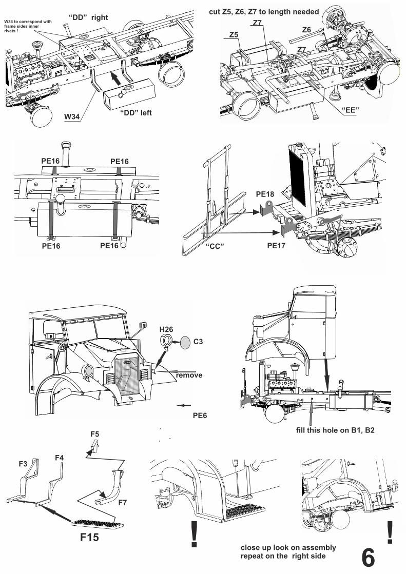
PE16 PE16
PE16 PE16
“DD” right
“DD” left
“CC”
“EE”
Z6Z5
Z7
Z7
cut Z5, Z6, Z7 to length needed
remove
H26
C3
PE6
F3F4
F5
F7
fill this hole on B1, B2
! !close up look on assemblyrepeat on the right side
F15
6
PE17
PE18
W34
W34 to correspond with frame sides innerrivets !

E1
E2
Assemble wheels
Interior decals
Painting - olive drab, some trucks were painted in usual 2 or 3 color camo, depending on army andservice used, sand yellow common in desert serviceNice camo examples available at: http://www.german.o5m6.de/Markings - see dashboard above and examples on next page
Part list: 1x various parts Z 1x body parts G 1x Cab11 parts H 1x clear parts parts C 1x engine parts A 1x frame parts B 1x under chassis parts C
2x under chassis parts D 1x various parts E 2x under chassis parts F 1x wheels parts S 1x under chassis parts W4x tyre, PE detail set, selection of wire
15
7

Canadian service
German service
British service 8