Embed Size (px)
Citation preview

CLICK I/O Module Specifications
C0-04RTD $149.004-Channel RTD Input Module4-channel RTD input module, 16-bit resolution (+/-0.1 degrees Celsius or Fahrenheit), supports: Pt100, Pt1000, JPt100, Cu10, Cu25, Ni120. Resistive ranges also supported, removable terminal block included. (replace-ment ADC p/n C0-16TB).
C0-04RTDPt, Cu, Ni, RES
INPUT
COMR1+R1–R1CCOMCOMR2+R2–R2CCOMCOMR3+R3–R3CCOMCOMR4+R4–R4CCOM
C0-04RTDPt, Cu, Ni, RES
INPUT
COMR1+R1–R1CCOMCOMR2+R2–R2CCOMCOMR3+R3–R3CCOMCOMR4+R4–R4CCOMRn+
Rn-RnC
Connectunusedchannels
Wiring Diagram
Not Compatible with ZIPLink Pre-Wired PLC Connection
Cables and Modules.
Input SpecificationsInputs per Module 4
Common Mode Range ±2.5 VCommon Mode Rejection 100 dB at DC and 100 dB at 50/60 HzInput Impedance >5 Mq
Maximum Ratings Fault protected inputs to ±50 VDC
Resolution ±0.1°C or °F, 0.1q or 0.01q
Input Ranges* Pt100: -200 to 850°C (-328 to 1562°F)Pt1000: -200 to 595°C (-328 to 1103°F)JPt100: -100 to 450°C (-148 to 842°F)10q Cu: -200 to 260°C (-328 to 500°F)25q Cu: -200 to 260°C (-328 to 500°F)120q Ni: -80 to 260°C (-112 to 500°F)0 to 3125.0q : Resolution 0.1q0 to 1562.5q : Resolution 0.1q0 to 781.2q : Resolution 0.1q0 to 390.62q : Resolution 0.01q0 to 195.31q : Resolution 0.01q
RTD Linearization AutomaticExcitation Current (All Ranges) 210 μAAccuracy vs. Temperature ±10 ppm per °C maximum
RTD Input Maximum Inaccuracy ±3°C (excluding RTD error); ±5°C (ranges Cu10 and Cu25)
RTD Linearity Error (End to End)
±2°C maximum, ±0.5°C typical, monotonic with no missing codes
Resistance Input Maximum Zero Scale Error
±0.0015% of full scale range in ohms (negligible)
Resistance Input Maximum Full Scale Error
±0.02% of full scale range
Maximum Linearity Error ±0.015% of full scale range maximum at 25°C, monotonic with no missing codes
Resistance Maximum Input Inaccuracy
0.1% at 0 to 60°C (32° to 140° F), typical 0.04% at 25°C (77° F)
Warm Up Time 30 minutes for ±1°C repeatabilitySingle Channel Update Rate 240ms
All Channel Update Rate Single Channel Update Rate times the num-ber of enabled channels on the module
Open Circuit Detection Time Positive full-scale reading within 2 seconds
Conversion Method Sigma - Delta
* While it is possible to use different resistive ranges, we recommend using the narrowest range that covers the resistance being measured. For example, if measuring approximately 100 ohms resistance, use the 0 to 195.31ohms range. While the resolution is the same as the 0 to 390.62 ohms range, output RMS noise will be lower and stability will be improved.
General SpecificationsField to Logic Side Isolation No isolation
External DC Power Required NoneBus Power Required (24 VDC) 25 mAThermal Dissipation 2.047 BTU per hourTerminal Block Replacement ADC p/n C0-16TB
Weight 3.1 oz (86 g)
These COM terminals are isolated.
NOTE: When using this module you must also use CLICK programming software and PLC firmware version V1.40 or later.
NOTE: The C0-04RTD module cannot be used with thermistors.
C0-04RTD Initialization TimeThe Number of Channels Used
The same Input Type is selected for all Channels
Mixed Input Types are selected
1 4 sec N/A2 5 sec May take up to 13 sec3 6 sec May take up to 18 sec4 7 sec May take up to 24 sec
NOTE: When this module is used in a CLICK PLC system, it may take up to 24 seconds for initialization after power-up (see the table below). During this time period, the RUN LED on the PLC Unit blinks to indicate the initialization process.
1 - 8 0 0 - 6 3 3 - 0 4 0 5tCLP-110 CLICK PLCs
For the latest prices, please check AutomationDirect.com.
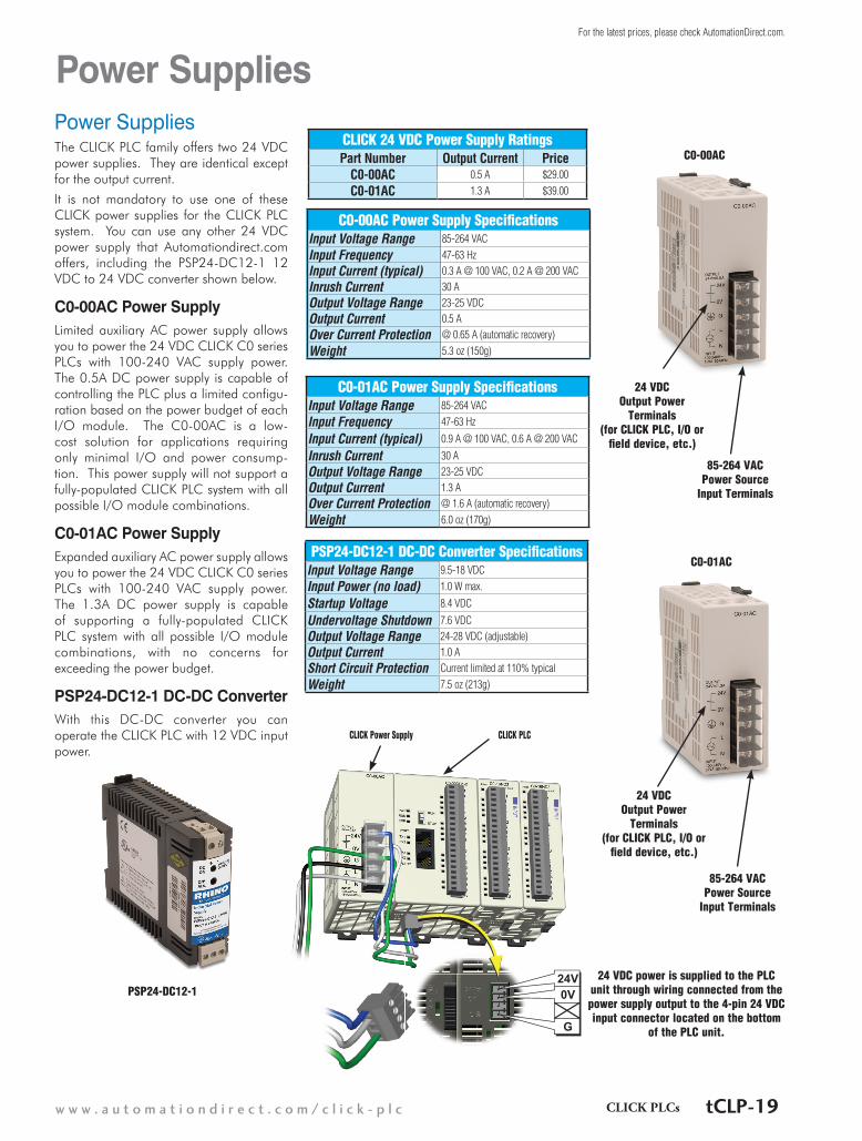
Power SuppliesThe CLICK PLC family offers two 24 VDC power supplies. They are identical except for the output current.
It is not mandatory to use one of these CLICK power supplies for the CLICK PLC system. You can use any other 24 VDC power supply that Automationdirect.com offers, including the PSP24-DC12-1 12 VDC to 24 VDC converter shown below.
C0-00AC Power SupplyLimited auxiliary AC power supply allows you to power the 24 VDC CLICK C0 series PLCs with 100-240 VAC supply power. The 0.5A DC power supply is capable of controlling the PLC plus a limited configu-ration based on the power budget of each I/O module. The C0-00AC is a low-cost solution for applications requiring only minimal I/O and power consump-tion. This power supply will not support a fully-populated CLICK PLC system with all possible I/O module combinations.
C0-01AC Power SupplyExpanded auxiliary AC power supply allows you to power the 24 VDC CLICK C0 series PLCs with 100-240 VAC supply power. The 1.3A DC power supply is capable of supporting a fully-populated CLICK PLC system with all possible I/O module combinations, with no concerns for exceeding the power budget.
PSP24-DC12-1 DC-DC ConverterWith this DC-DC converter you can operate the CLICK PLC with 12 VDC input power.
Power Supplies
CLICK 24 VDC Power Supply RatingsPart Number Output Current Price
C0-00AC 0.5 A $29.00
C0-01AC 1.3 A $39.00
C0-00AC Power Supply SpecificationsInput Voltage Range 85-264 VAC
Input Frequency 47-63 HzInput Current (typical) 0.3 A @ 100 VAC, 0.2 A @ 200 VACInrush Current 30 AOutput Voltage Range 23-25 VDCOutput Current 0.5 AOver Current Protection @ 0.65 A (automatic recovery)
Weight 5.3 oz (150g)
C0-01AC Power Supply SpecificationsInput Voltage Range 85-264 VAC
Input Frequency 47-63 Hz
Input Current (typical) 0.9 A @ 100 VAC, 0.6 A @ 200 VAC
Inrush Current 30 AOutput Voltage Range 23-25 VDCOutput Current 1.3 AOver Current Protection @ 1.6 A (automatic recovery)
Weight 6.0 oz (170g)
24V0V
G
CLICK PLCCLICK Power Supply
24 VDC power is supplied to the PLC unit through wiring connected from the power supply output to the 4-pin 24 VDC input connector located on the bottom
of the PLC unit.
24 VDC Output Power
Terminals (for CLICK PLC, I/O or
field device, etc.)
85-264 VAC Power Source
Input Terminals
24 VDC Output Power
Terminals (for CLICK PLC, I/O or
field device, etc.)
85-264 VAC Power Source
Input Terminals
PSP24-DC12-1 DC-DC Converter SpecificationsInput Voltage Range 9.5-18 VDC
Input Power (no load) 1.0 W max.
Startup Voltage 8.4 VDC
Undervoltage Shutdown 7.6 VDCOutput Voltage Range 24-28 VDC (adjustable)Output Current 1.0 AShort Circuit Protection Current limited at 110% typical
Weight 7.5 oz (213g)
PSP24-DC12-1
C0-01AC
C0-00AC
w w w . a u t o m a t i o n d i r e c t . c o m / c l i c k - p l c CLICK PLCs tCLP-19
For the latest prices, please check AutomationDirect.com.

Power Budgeting
Other 24 VDC Power Supply Example: PSP24-60S
CLICK 24 VDC Power Supply C0-00AC or C0-01AC
Power Consumption for CLICK PLC Units
Power BudgetingThere are two areas to be considered when determining the power required to operate a CLICK PLC system. The first area is the power required by the CLICK PLC, along with the internal logic side power that the CPU provides to its own I/O and any connected I/O modules that are powered through the PLC expansion port; plus any device, such as a C-more Micro-Graphic panel, that is powered through one of the communications ports.
The second area is the power required by all externally connected I/O devices. This should be viewed as the field side power required. The field side power is dependent on the voltage used for a particular input or output device as it relates to the wired I/O point, and the calculated load rating of the connected device.
It is strongly recommended that the power source for the logic side be separate from the power source for the field side to help eliminate possible electrical noise.
Power budgeting requires the calculation of the total current the 24 VDC power source needs to provide to CLICK’s logic side, and also a separate calculation of the total current required for all devices operating from the field side of the PLC system.
Refer to the Power Budgeting example shown on the following page. The table shows required current for a CLICK PLC, two I/O modules, and a C-more Micro. Use the total amperage values to select the properly sized power supply.
PLC Current Consumption (mA)
Part NumberPower Budget
24 VDC (logic side)
External 24 VDC
(field side)Basic PLC Units
C0-00DD1-D 120 60C0-00DD2-D
120 0C0-00DR-DC0-00AR-D
Standard PLC UnitsC0-01DD1-D 140 60
C0-01DD2-D140 0C0-01DR-D
C0-01AR-DAnalog PLC Units
C0-02DD1-D 140 60C0-02DD2-D
140 0C0-02DR-D
Ethernet Basic PLC UnitsC0-10DD1E-D 120 60C0-10DD2E-D
120 0C0-10DRE-DC0-10ARE-D
Ethernet Standard PLC UnitsC0-11DD1E-D 140 60
C0-11DD2E-D140 0C0-11DRE-D
C0-11ARE-D
PLC Current Consumption (mA)
Part NumberPower Budget
24 VDC (logic side)
External 24 VDC
(field side)Ethernet Analog PLC Units
C0-12DD1E-D140
60C0-12DD2E-D
0C0-12DRE-D160
C0-12ARE-DC0-12DD1E-1-D
14060
C0-12DD2E-1-D0C0-12DRE-1-D
160C0-12ARE-1-DC0-12DD1E-2-D
14060
C0-12DD2E-2-D0C0-12DRE-2-D 160
C0-12ARE-2-D 140
1 - 8 0 0 - 6 3 3 - 0 4 0 5tCLP-20 CLICK PLCs
For the latest prices, please check AutomationDirect.com.

Ethernet Basic PLC
Analog PLC UnitsThe Analog CLICK PLC units are available with different combinations of DC in, DC sinking, sourcing or relay out, and analog in and out.
They also have an RS-485 port for Modbus and ASCII communications, and the battery backup feature which will retain the data in SRAM for 3 years (battery sold separately; part no. D2-BAT-1).
The table lists the part numbers showing the various I/O type combinations.
C0-02DD1-D
C1
X1
X2
X3
X4
C2
Y1
Y2
Y3
Y4
+V
AD1V
AD1I
AD2V
AD2I
ACOM
DA1V
DA1I
DA2V
DA2I
RS-485PORT3
PORT2
PORT1
PWR
RUN
ERR
TX2
RX2
TX1
RX1
TX3
RX3
CommunicationPorts
LED StatusIndicators
PLC ModeSwitch 4 Discrete
Inputs
4 DiscreteOutputs
2 AnalogInputs
2 AnalogOutputs
Analog PLCs
Part NumberDiscrete
Input Types
Discrete Output Types Analog Input Types Analog Output
TypesExternal Power
C0-02DD1-D
4 DC (sink/source)
4 DC (sink)2 channel; voltage (0-5 VDC) / current (4–20 mA); selectable separately per channel; 12 bit
2 channel; voltage (0-5 VDC) / current sinking (4–20 mA); selectable separately per channel; 12 bit
24 VDC (required for all PLCs)
C0-02DD2-D 4 DC (source)
C0-02DR-D 4 relay
Choosing a PLC Unit
Ethernet Basic PLCsPart Number Discrete Input Type Discrete Output Type External Power
C0-10DD1E-D8 DC (sink/source)
6 DC (sink)
24VDC (required for all PLCs)
C0-10DD2E-D 6 DC (source)C0-10DRE-D
6 RelayC0-10ARE-D 8 AC
C0-10DD1E-D
C1X1X2X3X4C2X5X6X7X8
C3Y1Y2Y3Y4C4Y5Y6+V
LNK/ACT
PORT1
PWR
RUN
ERR
RUN
STOP
PORT2
RS-232
TX2
RX2
100MBIT
ETHERNET
LED StatusIndicators
CommunicationPorts
PLC ModeSwitch
8 DiscreteInputPoints
6 DiscreteOutputPoints
X7X7X8X8
3C33C3Y1Y1Y2Y2Y3Y3Y4Y4
4C44C4Y5Y5Y6Y6
V+V
D-DD1E-
C1X1X2X3X4X4
2C22C2X5X5X6X6X7
C0-10D
RUNRUN
STOPSTOP
100MBITNET
PORT2
RS-232RS 232
TX2
RX2
100MBIT
ETHERLNK/ACT
PORT1
PWRPWR
RUN
ERR
RRRRRR
SSSS
Analog PLC
Ethernet Basic and Standard PLC Units
CLICK Ethernet Basic and Standard PLC units have one built-in Ethernet commu-nications port and one standard RS-232 serial communications port. Additionally, Ethernet Standard PLC Units have an RS-485 port for Modbus RTU and ASCII communication.
The Ethernet Basic and Standard CLICK PLC units are available with different combinations of built-in I/O types (i.e. DC input/DC output, DC input/relay output, and AC input/relay output). With the 14 built-in I/O points (8 inputs/6 outputs), the PLC Units can be used as a ready-to-go PLC control system without any additional I/O modules. The PLC Unit only requires a 24 VDC power supply.
The table on the right lists the PLC unit part numbers and the various I/O type combi-nations.
All Ethernet PLC Units have a battery backup feature which will retain the data in SRAM for 3 years (battery sold sepa-rately; part no. D2-BAT-1).
w w w . a u t o m a t i o n d i r e c t . c o m / c l i c k - p l c CLICK PLCs tCLP-23
For the latest prices, please check AutomationDirect.com.

Choosing a PLC Unit
RS-485
+_LG
C0-11DD1E-D
C1X1X2X3X4C2X5X6X7X8
C3Y1Y2Y3Y4C4Y5Y6+V
LNK/ACT
PORT1
PWR
RUN
ERR
RUN
STOP
PORT2
PORT3
RS-232
TX2
RX2
100MBIT
ETHERNET
TX3
RX3
LED StatusIndicators
CommunicationPorts
8 DiscreteInputPoints
6 DiscreteOutputPoints
PLC ModeSwitch
7X77X78X88X8
3C33C3Y1Y1
2Y22Y23Y33Y34Y44Y44C44C45Y56Y6V+V
NET
D-DD1E-
1C1X1
2X23X34X44X42C22C25X55X56X66X67X7
C0-11D
RRRUNRUN
SSTOPSTOPSSTOP
GLG
__++
100MBITNET
PORT2TX2
RX2
100MBIT100MBIT
RS-232RS 232
TXX3
RXX3
POORT3RS-
POORT3-48554855
ETHERNETETHER
LNK/ACT
PORT1
PWRPWR
RUN
ERR
RR
SSSS
Ethernet Standard PLC
Ethernet Analog PLC
RS-485
+_LG
C0-12DD1E-D
C1X1X2X3X4C2Y1Y2Y3Y4+VAD1VAD1IAD2VAD2IACOMDA1VDA1IDA2VDA2I
LNK/ACT
PORT1
PWR
RUN
ERR
RUN
STOP
PORT2
PORT3
RS-232
TX2
RX2
100MBIT
ETHERNET
TX3
RX3
LED StatusIndicators
CommunicationPorts
4 DiscreteInputPoints
2 or 4 AnalogInputPoints
2 AnalogOutputPoints
PLC ModeSwitch
4 DiscreteOutputPoints
3Y33Y34Y44Y4V+VV+V
VVD1ADD1ADID1ADD1ADV2VD2ADD2AD
2ID2ADD2ADMOCOACCOACVVA1DAA1DAIA1DAA1DAV2VA2DAA2DA
2IA2DAA2DA
NET
D-DDD1E-
1C1X1
2X23X34X44X42C22C2
Y1Y12Y22Y23Y3
C0-12D
RRRUNRUN
SSTOPSTOPSSTOP
GLG
__++
100MBITNET
PORT2TX2
RX2
100MBIT
RS-232RS 232
TXX3
RXX3
POORT3RS-
POORT3-48554855
ETHERNETETHER
LNK/ACT
PORT1
PWRPWR
RUN
ERR
RR
SSSS
Ethernet Standard PLCsPart Number Discrete Input Type Discrete Output Type External Power
C0-11DD1E-D8 DC (sink/source)
6 DC (sink)
24V DC (required for all PLCs)
C0-11DD2E-D 6 DC (source)C0-11DRE-D
6 RelayC0-11ARE-D 8 AC
Ethernet Analog PLC Units
CLICK Ethernet Analog PLC units have one built-in Ethernet communications port, one standard RS-232 serial communications port and an RS-485 port for Modbus RTU and ASCII communication.
The Ethernet Analog CLICK PLC units are available with different combinations of built-in discrete and analog I/O types i.e. DC input/DC output, DC input/relay output, and AC input/relay output, as well as built-in
analog inputs/outputs for both current and voltage. With the built-in I/O points, the PLC Units can be used as a ready-to-go PLC control system without any additional I/O modules. The PLC Unit only requires a 24 VDC power supply.
The table below lists the PLC Unit part numbers and the various I/O type com-binations.
All Ethernet PLC Units have a battery backup feature which will retain the data in SRAM for 3 years (battery sold separately; part no. D2-BAT-1).
Ethernet Analog PLCs
Part Number Discrete Input Type
Discrete Output Type Analog Input Types Analog Output Types External Power
C0-12DD1E-D4 DC (sink/source)
4 DC (sink) 2 channel; voltage (0–5 VDC) / current (4–20 mA);
selectable separately per chan-nel, 12 bit
2 channel; voltage (0–5 VDC) /
current sinking (4–20 mA); selectable separately per chan-
nel, 12 bit
24V DC (required for all PLCs)
C0-12DD2E-D 4 DC (source)C0-12DRE-D
4 RelayC0-12ARE-D 4 ACC0-12DD1E-1-D
4 DC (sink/source)
4 DC (sink)4 channel;
current (0–20 mA), 12 bit
2 channel; current sourcing (4–20 mA),
12 bit
C0-12DD2E-1-D 4 DC (source)C0-12DRE-1-D
4 RelayC0-12ARE-1-D 4 ACC0-12DD1E-2-D
4 DC (sink/source)
4 DC (sink)
4 channel; voltage (0–10 VDC), 12 bit
2 channel; voltage (0–10 VDC),
12 bit
C0-12DD2E-2-D 4 DC (source)C0-12DRE-2-D
4 RelayC0-12ARE-2-D 4 AC
1 - 8 0 0 - 6 3 3 - 0 4 0 5tCLP-24 CLICK PLCs
For the latest prices, please check AutomationDirect.com.

I/O ModulesA variety of discrete, combo, and analog I/O modules are available for the CLICK PLC system. Up to eight I/O modules can be connected to a CLICK PLC unit to expand the system I/O count and meet the needs of a specific application. Complete I/O module specifications and wiring diagrams can be found later in this section.
Choosing Expansion I/O Modules
C0-08ND3 C0-08ND3-1 C0-08NE3C0-16ND3 C0-08NAC0-16NE3
Discrete Input Modules
Discrete Input Modules
Part Number I/O Type/ Number/Commons
Sink or Source
Voltage Ratings
C0-08ND3 DC/8/2 Sink or Source 12-24 VDCC0-08ND3-1 DC/8/2 Sink or Source 3.3-5 VDCC0-16ND3 DC/16/4 Sink or Source 24 VDCC0-08NE3 AC/DC / 8/2 Sink or Source 24 VAC/VDCC0-16NE3 AC/DC / 16/4 Sink or Source 24 VAC/VDC
C0-08NA AC/8/2 N/A 100-120 VAC
Discrete Output Modules
C0-16TD1C0-08TD1 C0-08TD2 C0-16TD2 C0-08TA C0-04TRS C0-08TR
Discrete Output Modules
Part Number I/O Type/ Number/ Commons
Sink or Source
Voltage/Current Ratings
C0-08TD1 DC/8/2 Sink 3.3-27 VDC, 0.3 AC0-08TD2 DC/8/1 Source 12-24 VDC, 0.3 AC0-16TD1 DC/16/2 Sink 5-27 VDC, 0.1 AC0-16TD2 DC/16/2 Source 12-24 VDC, 0.1 AC0-08TA AC/8/2 N/A 17-240 VAC, 0.3 A
C0-04TRS Relay/4/4 N/A 6-27 VDC, 7 A 6-240 VAC, 7 A
C0-08TR Relay/8/2 N/A 6-27 VDC, 1 A 6-240 VAC, 1 A
w w w . a u t o m a t i o n d i r e c t . c o m / c l i c k - p l c CLICK PLCs tCLP-25
For the latest prices, please check AutomationDirect.com.

Wiring Solutions using the ZIPLink Wiring SystemZIPLinks eliminate the normally tedious process of wiring between devices by utilizing prewired cables and DIN rail mount connector modules. It’s as simple as plugging in a cable connector at either end or terminating wires at only one end. Prewired cables keep installa-tion clean and efficient, using half the space at a fraction of the cost of stan-dard terminal blocks.
ZIPLinks are available in a variety of styles to suit your needs, including feedthrough connector module. ZIPLinks are avail-able for all Basic, Standard and Ethernet CLICK PLC units and
most discrete and analog I/O modules. Pre-printed I/O-specific adhesive label strips for quick marking of ZIPLink modules are provided with ZIPLink cables.
Wiring System for CLICK PLCs
Use the “CLICK PLC PLC Unit ZIPLink Selector” table and CLICK I/O ZIPLink selector tables located in this section:
1. Locate your PLC or I/O module. 2. Select a ZIPLink Module. 3. Select a corresponding ZIPLink Cable.
Solution 1: CLICK PLC and I/O Modules to ZIPLink Connector ModulesWhen looking for quick and easy I/O-to-field termination, a ZIPLink connector module used in conjunction with a prewired ZIPLink cable, consisting of an I/O terminal block at one end and a multi-pin connector at the other end, is the best solution.
Solution 2: CLICK PLC and I/O Modules to 3rd Party DevicesWhen wanting to connect I/O to another device within close prox-imity of the I/O modules, no extra terminal blocks are necessary when using the ZIPLink Pigtail Cables. ZIPLink Pigtail Cables are prewired to an I/O terminal block with color-coded pigtail with soldered-tip wires on the other end.
Use the I/O Modules to 3rd Party Devices selector tables located in the ZIPLink section:
1. Locate your PLC or I/O module. 2. Select a ZIPLink Pigtail Cable that
is compatible with your 3rd party device.
Solution 3: GS Series and DuraPulse Drives Communication CablesNeed to communicate via Modbus RTU to a drive or a network of drives?
ZIPLink cables are available in a wide range of configurations for connecting to PLCs and SureServo, SureStep, Stellar Soft Starter and AC drives. Add a ZIPLink communications module to quickly and easily set up a multi-device network.
Use the Drives Communication selector tables located in the ZIPLink section:
1. Locate your Drive and type of communications. 2. Select a ZIPLink cable and other associated hardware.
Solution 4: Serial Communications CablesZIPLink offers communications cables for use with CLICK PLCs that can also be used with other communications devices. Connections include a 6-pin RJ12 connector which can be used in conjunction with the RJ12 Feedthrough module.
Use the Serial Communications Cables selector table located in the ZIPLink section:
1. Locate your connector type 2. Select a cable.
w w w . a u t o m a t i o n d i r e c t . c o m / c l i c k - p l c CLICK PLCs tCLP-35
For the latest prices, please check AutomationDirect.com.

CLICK PLC Discrete Input Module ZIPLink SelectorI/O Module ZIPLink
Input Module # of Terms Component Module Part
No.Cable Part No.
C0-08ND3
11 Feedthrough ZL-RTB20 ZL-C0-CBL11 *C0-08ND3-1C0-08NE3C0-08NA
C0-16ND3 20Feedthrough ZL-RTB20
ZL-C0-CBL20 *Sensor ZL-LTB16-24
C0-16NE3 20Feedthrough ZL-RTB20Sensor ZL-LTB16-24
CLICK PLC ZIPLink SelectorPLC ZIPLink
PLC Unit # of Terms Component Module
Part No.Cable
Part No.C0-00DD1-D
20 Feedthrough ZL-RTB20 ZL-C0-CBL20 *
C0-00DD2-DC0-00DR-DC0-00AR-DC0-01DD1-DC0-01DD2-DC0-01DR-DC0-01AR-DC0-02DD1-D
No ZIPLinks are available for Analog PLC units. C0-02DD2-DC0-02DR-DC0-10DD1E-D
20 Feedthrough ZL-RTB20 ZL-C0-CBL20 *
C0-10DD2E-DC0-10DRE-DC0-10ARE-DC0-11DD1E-DC0-11DD2E-DC0-11DRE-DC0-11ARE-DC0-12DD1E-D
No ZIPLinks are available for Ethernet Analog PLC units.
C0-12DD2E-DC0-12DRE-DC0-12ARE-DC0-12DD1E-1-DC0-12DD2E-1-DC0-12DRE-1-DC0-12ARE-1-DC0-12DD1E-2-DC0-12DD2E-2-DC0-12DRE-2-DC0-12ARE-2-D
CLICK PLC Combo I/O Module ZIPLink SelectorI/O Module ZIPLink
Combo Module # of Terms Component Module
Part No.Cable
Part No.C0-16CDD1
20 Feedthrough ZL-RTB20 ZL-C0-CBL20 *C0-16CDD2C0-08CDR 11 Feedthrough ZL-RTB20 ZL-C0-CBL11 *
CLICK PLC Discrete Output Module ZIPLink SelectorI/O Module ZIPLink
Output Module # of Terms Component Module
Part No.Cable
Part No.C0-08TD1
11 Feedthrough ZL-RTB20 ZL-C0-CBL11 *C0-08TD2C0-08TRC0-08TA
C0-16TD1 20Feedthrough ZL-RTB20
ZL-C0-CBL20*Fuse ZL-RFU20 2
Relay (sinking) ZL-RRL16-24-1
C0-16TD2 20
Feedthrough ZL-RTB20
ZL-C0-CBL20 *Fuse ZL-RFU20 2
Relay (sourcing) ZL-RRL16-24-2C0-04TRS1 20 Feedthrough ZL-RTB20 ZL-C0-CBL20 *
1 Note: The C0-04TRS relay output is derated not to exceed 2A per point maximum when used with the ZIPLink wiring system.
2 Note: Fuses (5 x 20 mm) are not included. See Edison Electronic Fuse section for (5 x 20 mm) fuse. S500 and GMA electronic circuit protection for fast-acting maximum protection. S506 and GMC electronic circuit protection for time-delay performance. Ideal for inductive circuits. To ensure proper operation, do not exceed the voltage and current rating of ZIPLink module. ZL-RFU20 = 2A per circuit.
CLICK PLC Analog I/O Module ZIPLink SelectorI/O Module ZIPLink
Analog Module
# of Terms Component Module
Part No.Cable
Part No.C0-04AD-1 11 Feedthrough ZL-RTB20 ZL-C0-CBL11 *C0-04AD-2 11 Feedthrough ZL-RTB20 ZL-C0-CBL11 *C0-04RTD 20 No ZIPLinks are available for RTD and thermocouple
modules.C0-04THM 11C0-04DA-1 11 Feedthrough ZL-RTB20 ZL-C0-CBL11 *C0-04DA-2 11 Feedthrough ZL-RTB20 ZL-C0-CBL11 *C0-4AD2DA-1 20 Feedthrough ZL-RTB20 ZL-C0-CBL20 *C0-4AD2DA-2 20 Feedthrough ZL-RTB20 ZL-C0-CBL20 *
Wiring System for CLICK PLCs
* Select the cable length by replacing the * with: Blank = 0.5m, -1 = 1.0m, or -2 = 2.0m.
1 - 8 0 0 - 6 3 3 - 0 4 0 5tCLP-36 CLICK PLCs
For the latest prices, please check AutomationDirect.com.