Embed Size (px)
Citation preview

Floor systems guide
COFRASOL
COFRAPLUS
COFRASTRA
COFRASTRA DÉCIBEL
COFRADAL 200
GLOBALFLOOR
SUPPORTSOL
SUPPORTSOL DÉCIBEL
COFRATHERM

FFaammiilliieess DDeessiiggnnaattiioonn SSyysstteemmss
FFlloooorrss oonn sseellff--ssuuppppoorrttiinngg COFRASOL ® Cofrasol 39
ffoorrmmwwoorrkk Cofrasol 40
Cofrasol 60
Cofrasol 118
CCoommppoossiittee fflloooorrss
Composite floors with COFRAPLUS ® Cofraplus 60
open-ribs Cofraplus 77
Composite floors with COFRASTRA ® Cofrastra 40
high bonding capacity Cofrastra 70
Multifonction composite COFRASTRA DÉCIBEL ® Cofrastra Décibel 40
floors Cofrastra Décibel 70
COFRADAL ® Cofradal 200
COFRADAL DÉCIBEL ® Cofradal 200 Décibel
DDrryy fflloooorrss SUPPORTSOL ® Supportsol 4
Supportsol 56
Supportsol 74
Supportsol 118
SUPPORTSOL DÉCIBEL ® Supportsol Décibel
Arval® flooring systems are covered by patents and registered trademarks.
Arval
Arval f loor systems gu ide
A r v a l f l o o r ® s y s t e mo f f e r
COFRATHERM ®
0
Supportsol 170
® flooring systems not available in South Africa.
PPrreeffaabbrriiccaatteed *d fflloooorr
Cofratherm*
*Arval

Arval
i n t r o d u c t i o n
1Arval f loor systems guide
Arval presents to you its range of floor construction
systems. This range is the most comprehensive on the market
and consists of both well established systems and innovative
solutions which reflect recent developments in regulation,
design and installation.
Arval has drawn on more than 30 years of experience in the
completion of thousands of international projects in all types
of buildings – both new-build and renovation. Most importantly,
in every country Arval is by your side from the project design
and engineering stage to the execution stage with professional
teams who analyse your project, propose the best solutions for
your requirements, and provide you with continuous technical
assistance both for design calculations and layout drawings,
right through to the initial building work.

Arval
t a b l e o f c o n t e n t s
2Arval f loor systems guide
■ BU I LD I NG
The key benefits of Arval floorssystems. . . . . . . . . . . . . . . . . . . . . . . . . . . . . . . 6Formwork function and speedof implementation. . . . . . . . . . . . . . . . . . . . . . . . . 6A finished and sealed underside . . . . . . . . . . . . . 6A floor bringing safety to the work site . . . . . . . 7Overall savings . . . . . . . . . . . . . . . . . . . . . . . . . . . 7Fire behaviour . . . . . . . . . . . . . . . . . . . . . . . . . . . . 7
Arval floor systems offer. . . . . . . . . . . . 8
Floors on self-supporting formwork
Cofrasol . . . . . . . . . . . . . . . . . . . . . . . . . . . . . . . . . 9
Composite floors. . . . . . . . . . . . . . . . . . . . . . . . . . 10Cofraplus . . . . . . . . . . . . . . . . . . . . . . . . . . . . . . . 11Cofrastra . . . . . . . . . . . . . . . . . . . . . . . . . . . . . . . 12Cofrastra Décibel . . . . . . . . . . . . . . . . . . . . . . . . 13
Prefabricated floors . . . . . . . . . . . . . . . . . . . . . . . 14Cofradal 200 . . . . . . . . . . . . . . . . . . . . . . . . . . . . 14Cofradal 200 Décibel . . . . . . . . . . . . . . . . . . . . . 15
Dry floors . . . . . . . . . . . . . . . . . . . . . . . . . . . . . . . 16Supportsol . . . . . . . . . . . . . . . . . . . . . . . . . . . . . 16Supportsol Décibel . . . . . . . . . . . . . . . . . . . . . . 17Cofratherm . . . . . . . . . . . . . . . . . . . . . . . . . . . . . 17
The decisive advantagesof Arval floor system . . . . . . . . . . . . . . . 18
Reference projects . . . . . . . . . . . . . . . . . 20Renovation . . . . . . . . . . . . . . . . . . . . . . . . . . . . . . 21Elevated car parks . . . . . . . . . . . . . . . . . . . . . . . . 22Underground car parks . . . . . . . . . . . . . . . . . . . . 24Office buildings . . . . . . . . . . . . . . . . . . . . . . . . . . 26Activity buildings and shopping centres . . . . . . . 28Collective and individual housing . . . . . . . . . . . . 30Non-residential buildings: health, schools,
infrastructures… . . . . . . . . . . . . . . . . . . . . . . . . . . 31
Sustainable development . . . . . . . . . 32
How to choose the most suitablesystem?. . . . . . . . . . . . . . . . . . . . . . . . . . . . . . 34
■ DES IG N I NG
Arval floor system frames . . . . . . . . . 38
Performance of Arval compositefloor systems . . . . . . . . . . . . . . . . . . . . . . . 39
Compliance of Arval floor systemswith regulations . . . . . . . . . . . . . . . . . . . . 42
Design criteria . . . . . . . . . . . . . . . . . . . . . . 44Floor thickness . . . . . . . . . . . . . . . . . . . . . . . . . . 44Deflection. . . . . . . . . . . . . . . . . . . . . . . . . . . . . . . 45Natural frequency . . . . . . . . . . . . . . . . . . . . . . . . 45Reinforcement . . . . . . . . . . . . . . . . . . . . . . . . . . . 46Support structures . . . . . . . . . . . . . . . . . . . . . . . 48Laying methods. . . . . . . . . . . . . . . . . . . . . . . . . . 49Steel girdering. . . . . . . . . . . . . . . . . . . . . . . . . . . 50Steel girdering. . . . . . . . . . . . . . . . . . . . . . . . . . . 52Floor openings. . . . . . . . . . . . . . . . . . . . . . . . . . . 53
Fire behaviour . . . . . . . . . . . . . . . . . . . . . . 54
Acoustic behaviour . . . . . . . . . . . . . . . . . 56
Thermal insulation . . . . . . . . . . . . . . . . . 58
Use in seismic areas . . . . . . . . . . . . . . . 60
Design examples . . . . . . . . . . . . . . . . . . . 61

Arval
3
T A B L E O F C O N T E N T S
Arval f loor systems guide
■ CALCU LAT I NG
GlobalFloor software . . . . . . . . . . . . . . . 68
■ IMPLEMENT I NG
Implementation sequences . . . . . . . 72
The ten commandmentsof laying . . . . . . . . . . . . . . . . . . . . . . . . . . . . . 74
Handling and storage . . . . . . . . . . . . . . 75
Deck fixing techniques. . . . . . . . . . . . . 76Cofrastra 40. . . . . . . . . . . . . . . . . . . . . . . . . . . . . 77Cofrastra 70. . . . . . . . . . . . . . . . . . . . . . . . . . . . . 77Decks with open ribs:Cofraplus, Cofrasol . . . . . . . . . . . . . . . . . . . . . . . 77
Deck laying. . . . . . . . . . . . . . . . . . . . . . . . . . 78Standard section floor decks . . . . . . . . . . . . . . . 78Changing floor deck direction . . . . . . . . . . . . . . 78Floor decks on intermediate supports . . . . . . . 79Deck ends . . . . . . . . . . . . . . . . . . . . . . . . . . . . . . 80Rebate laying on reinforced concrete beams . . 81Threading of main beam . . . . . . . . . . . . . . . . . . 82Placing props. . . . . . . . . . . . . . . . . . . . . . . . . . . . 84Bearing on brickwork . . . . . . . . . . . . . . . . . . . . . 85Overhang . . . . . . . . . . . . . . . . . . . . . . . . . . . . . . . 86Trimmers and floor openings. . . . . . . . . . . . . . . 87Composite beam - connectors . . . . . . . . . . . . . . 88
Laying of Cofradal 200 . . . . . . . . . . . . . 89
Cofra software . . . . . . . . . . . . . . . . . . . . 66

Building
Arval
4Arval f loor systems guide

Sport City Tower, Doha (Qatar)
ARCHITECT: Concept Architect
Hadi Simaan, Florida (USA)
STRUCTURE: Arup, London (United Kingdom)
Arval
5Arval f loor systems guide
Arval bu i l d i n g
t h e k e y b e n e f i t s o fA r v a l f l o o r s y s t e m s
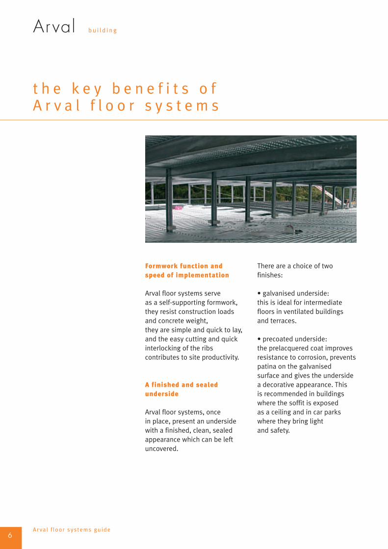
Formwork function andspeed of implementation
Arval floor systems serveas a self-supporting formwork,they resist construction loadsand concrete weight,they are simple and quick to lay,and the easy cutting and quickinterlocking of the ribscontributes to site productivity.
A finished and sealedunderside
Arval floor systems, oncein place, present an undersidewith a finished, clean, sealedappearance which can be leftuncovered.
There are a choice of twofinishes:
• galvanised underside:this is ideal for intermediatefloors in ventilated buildingsand terraces.
• precoated underside:the prelacquered coat improvesresistance to corrosion, preventspatina on the galvanisedsurface and gives the undersidea decorative appearance. Thisis recommended in buildingswhere the soffit is exposedas a ceiling and in car parkswhere they bring lightand safety.
6Arval f loor systems guide

Arval bu i l d i n g
A floor bringing safetyto the work site
The laying of Arval floor systemscreates a continuous workingplatform that allows site workersto walk over several completelevels of the constructionstraight away.
The floor can be safely walkedon once it is fixed to thesupports.
Overall savings
Implementing factory-producedindustrial systems usingexpert technology and anacknowledged speed of layingbrings substantial savingsin terms of construction costscompared to a reinforcedconcrete floor.The hollows between ribsreduce concrete consumptionby up to 100 kg/m2.
Savings in reinforcements mayreach up to 6 kg/m2 comparedto a solid concrete slab.The lightness of the Arval floorsystems provides structuralsavings (one or two beamsections) and foundationsavings, and also enables easierrenovation, modification orextension of buildings.
Fire behaviour
All of our solutions providea firestop response of up to3 hours. Actual fire testsperformed at scale 1 at the CNPP(national prevention andprotection centre) in Vernon,demonstrated exceptionalperformance with no collapseusing Arval steel solutions.
7
T H E B E N E F I T S
Arval f loor systems guide

Arval bu i l d i n g
A r v a l f l o o r s y s t e mo f f e r
Arval benefits from acknowledgedexperience in the design andmanufacturer of floor systems forthe construction of buildings andoffers the most comprehensiverange available on the market.
Our company has the advantageof three decades of experiencein this field, with know-howmanifested not only in thetechnical and economicalperformance of the floorsystems but also in the qualityand reliability of the servicesoffered to its customers. Wehave completed manyinternational projects.
A range of solutions adaptedto floors
Arval floor systems are madeup of galvanised decks orgalvanised-precoated decks.
These profiles, carefullycombined with materials suchas concrete, thermal- andacoustic-insulation, plaster,and wood, form advancedconstruction systems intendedfor all types of structureswhere their effectivenessand reliability is proven.
Arval floor systems are used inall girder structures or supportwalls:• steel,• reinforced or prestressedconcrete,
• brickwork load-bearing walls,• wood.
The very wide range of Arvalfloor solutions respondsto all your requirements
Four families of Arval floorsare available according tothe requirements and final useof the building:• floors on self-supportingpermanent formwork: Cofrasol
Cofrastra• prefabricated floors: Cofradal• dry floors: Supportsol,
Cofratherm and SupportsolDécibel.
All Arval floors are subject to aspecification sheet specifyingthe spans, loads, and• scope of application• definition of regulations• technical characteristics• additional stipulations.
These slabs are combined withthe floor joists to enable easyconstruction of 14-18 m clear-span floors for office buildings:globalFloor.
Each floor constructionsystem takes into accountthe requirements relatingto sustainable development.It is environmentally and userfriendly.
Arval plays an active rolein sustainable constructionby using steel solutions thatprovide a guarantee of safetyand comfort to both usersand construction workers.
8Arval f loor systems guide
• composite floors: Cofraplus and

Arval bu i l d i n g
cofrasol
Cofrasol floors are made upof steel decks used to provideformwork for the reinforcedconcrete when it is poured.
Cofrasol floors are made upof steel decks used to provideformwork for the reinforcedconcrete when it is poured.
For slabs on self-supportingpermanent formwork, the deckis only stressed during theconstruction stage.
It receives the poured concreteand bears its weight until theconcrete sets. Then, the appliedloads are borne exclusivelyby the reinforced concrete slabwhich is therefore designedfor this function.
The steel deck is self-supportingand is no longer taken intoaccount in the final floorresistance.
Cofrasol floors are availablein a range of four profiles:Cofrasol 39, Cofrasol 40,Cofrasol 60, and Cofrasol 118,depending on the desired span.
These cover many fields ofapplication, such as car parks,offices, and renovation projects.
9
S Y S T E M O F F E R
■ F L O O R S O N S E L F - S U P P O R T I N G F O R M W O R K
Arval f loor systems guide

S Y S T E M O F F E R
Arval bu i l d i n g
Composite floor systems combinethe beneficial features of steel andconcrete. Steel is an excellentmaterial for working under tensionand concrete is an excellentmaterial for working undercompressive stress.
If the steel deck is made withembossments, these makethe concrete slab and the steeldecks interdependent andthey work together to producethe composite resistance ofthe floor. We therefore referto composite floors or slabs.
A composite floor is designedin two different stages: theassembly and concrete-pouringstage, and then the compositestage. During the assemblyand concrete-pouring stage,the deck is used as self-supporting formwork andprovides a working platform.
In the composite stage, the deckis structurally combined withhardened concrete (compositeaction) and completely orpartially replaces the tensilereinforcement of the slab.
Composite floor decks are usedto build floors in fields as variedas offices, housing, industrialbuildings, car parks, hospitals,and school buildings, either asnew construction or renovation.
10
■ C O M P O S I T E F L O O R S
Arval f loor systems guide
Fabrication of a composite floor deck

Arval bu i l d i n g
11
S Y S T E M O F F E R
Arval f loor systems guide
Open-rib composite floor decks:cofraplus
These are made up of two open-rib trapezoidaland nestable decks with embossments for easystorage and transportation. Cofraplus is the bestsolution for most uses involving spans up to 4.5 m.
cofraplus 60
Cofraplus 60 guarantees economicaltransportation and quick installation.The deck is manufactured from0.75mm gauge steel and is designedfor medium spans (up to 3.60m)without props over 2 continuousbays, and slab thicknessesof 10 to 28 cm.
cofraplus 77
Cofraplus 77 benefits from theadvantages of the Cofraplus rangeand takes its performance further.
• It exceeds unpropped spansin the construction stage up to4.20 m with a thickness of 0.75 mmover two continuous bays• At an equivalent applied load,it exceeds greater spans in thecomposite stage and can be laidwith slabs with a thicknessof 12 to 28 cm.

Arval bu i l d i n g
12
S Y S T E M O F F E R
Arval f loor systems guide
Re-entrant-ribs composite floorsdecks: cofrastra
The Cofrastra family consists of two re-entrant notched ribdecks to tightly and integrally join the steel and concrete:Cofrastra 40 and Cofrastra 70.
Dove-tail shaped re-entrant ribs:• can provide anchor lines for suspending ceilingsand technical networks using Cofrafix clips fixedin place by hand,• create a very strong bond with the concrete.Cofrastra can support substantial live loadsand reach spans of up to 7 m. cofrastra 40
• is used to lay very thin (8 cm)or thick (20 cm) floors as it coverspractically the entire field ofconstruction with light and heavyloads.• easy to anchor ceilings usingspecial clips fitted into the closedribs.• benefits from very good fireresistance due to its narrow ribs.
cofrastra 70
• is especially adapted to unproppedmedium spans.• can be used with slabs of 11 to30 cm thickness and can bear veryheavy loads.• aims to lighten structures withheavy dead loads.• enables suspension of ceilingsusing special clips fitted intothe closed ribs.

Arval bu i l d i n g
13
S Y S T E M O F F E R
Arval f loor systems guide
Cofrastra 40 or Cofrastra 70 decksand the concrete poured on siteform a reinforced composite slab.
The bottom part consistsof a suspended ceiling madeup of plaster boards and glasswool, which is used as anacoustic insulation material.The presence of glass woolin the plenum space providesthe floor with the desiredthermal insulation, andthe plaster boards providefire stability, if needed,for the slab and beams.
Cofrastra Décibel offers anadvanced global constructionsolution for collective housingand office floor dividers.
Cofrastra Décibel easily adaptsto the regulatory requirementson thermal and soundinsulation, and on fire safety.
Multi-functional composite floors:cofrastra décibel
Cofrastra Décibel is a multi-functional floorcombining the best features of its differentcomponents.
Cofrastra 40 Décibel
Cofrastra 70 Décibel

S Y S T E M O F F E R
Arval bu i l d i n g
cofradal 200
Cofradal 200 is a floor systemthat is prefabricated in the factoryin elements 1.20 m wide withlengths up to 7 m. It incorporatesa specific tray, sound and thermalinsulation material, a weldmesh,and a concrete slab.
Cofradal 200 can be suppliedwithout a concrete screed, whichis then added on the buildingsite. The underside is galvanisedor precoated, and has a flat andclean surface.
With a dead weight of 200kg/m2, this ultra-light floorsystem offers considerablesavings in steel weight of theframework.
It is also the ideal solution forfast implementation withoutprops as it dispenses withpouring of the slab in situ.Cofradal covers an unproppedspan of 7.0 m.A Cofradal 200 PAC versionready to pour on site (hand-portable version in elementsof 600 mm) is available. Thisversion is particularly suitedto the renovation market.
14
■ P R E FA B R I C A T E D F L O O R S
Arval f loor systems guide

Arval bu i l d i n g
cofradal 200 décibel
In this form, the underside of the steeltray is perforated, thus giving theconstruction system excellent soundabsorption properties.
There are many possible fields of application,such as schools and offices.
15
S Y S T E M O F F E R
Arval f loor systems guide

S Y S T E M O F F E R
Arval bu i l d i n g
supportsol
In the dry floors product line,steel is a natural partnerof wood.
The Supportsol range consistsof trapezoidal-rib profiles,with wooden decking panelsscrewed onto the rib crownsto form an uninsulated dry floor.
The performance is providedby the steel profile only;the rigidity contributed bythe wooden panels is nottaken into account.
The range is made up of fiprofiles:• Supportsol 40,• Supportsol 56,• Supportsol 74• Supportsol 118
for spans from 0.8 m toapplied loads of over 13 kN/m2.
Supportsol is particularly usefulin modular construction.
16
■ D R Y F L O O R S
Arval f loor systems guide
• Supportsol 170
ve

Arval bu i l d i n g
cofratherm
Cofratherm is an insulated dry floor madeup of a Cofrastra 40 deck with thermal insulationmaterial placed in the upper part of the assembly.
Insulation is formed by injecting a polyurethane-foam layer into the re-entrant ribs of the deck.The top finish, which provides the walkingsurface, can be of wood fibreboard or fibre-cement sheet depending on the final use.
It has many uses outside the field of modularconstruction, such as renovation and buildingextensions.
17
S Y S T E M O F F E R
Arval f loor systems guide
supportsol décibel
Supportsol Décibel is an insulateddry-composite-floor system with amaximum span of 6 m.
It consists of a 200mm deep steel profilewith laminated wood panels screwedonto the top of the tray, a glass surfacingmat and a dry screed of plaster boards.The underside is made up of a suspendedceiling in the form of plaster boards,with glasswool introduced into the plenumspace.
It has many applications, including renovation,extensions, housing, and offices…

Arval bu i l d i n g
t h e d e c i s i v e a d v a n t a g e so f A r v a l f l o o r s y s t e m s
18Arval f loor systems guide
Cofrasol, Cofraplus andCofrastra floors
• Low weight – easy to handleThe steel trays are easy to liftand manoeuvre as they are rigid,light, and easy to grasp bythe ribs.There is typically no needto use heavy lifting equipmentfor lengths up to 10m.The trays are delivered onpallets, which ensure easytransportation, handling,and storage on site.
• Ease and speed of installationThe decks are manually laidwithout difficulty and installationis carried out quickly.The connections betweenthe decks, the accessoriesand the load-bearing frameworkare achieved using traditionalfixings.The formwork for the edge,generally comprised of edgetrims made from fabricatedgalvanised-steel sheet,is quickly attached.
• Well adapted to complexarchitecture and irregular shapesCutting the decks along an edgeat a skewed angle or arounda column is carried out as workprogresses using shears,nibblers, or saws. This is simple,and precise. It is also possibleto adjust the formworkat minimal expense.
Cofraplus and Cofrastracomposite floors
• Reinforcement bar gainThe closed and/or notched formof the ribs connect the steel andconcrete together. The naturalreinforcement created by thedeck enables bar reinforcementto be omitted from the concrete.In common applications, it issufficient to add an anti-crackmesh. The equivalent savingis between 2.2 and 6 kg of steelper m2 of floor.
• Composite constructionby connection of the compositeslab with the steel frameby shear studsThe connection of the compositeslab with the steel or concretebeams provides substantialsavings in steel or concrete,and can considerably reducebeam dimensions (up to 35%for floor joists).
• Horizontal bracingof the structureFixing decks during layingcontributes to the bracingof the supporting beamand joist arrangement.
Cofrastra high-bondingcomposite floors
• Easy suspension of servicesand suspended ceilings
• Guaranteed thermal and acousticinsulation performance
Arval bu i l d i n g
19
T H E D E C I S I V E A D VA N T A G E S
Arval f loor systems guide
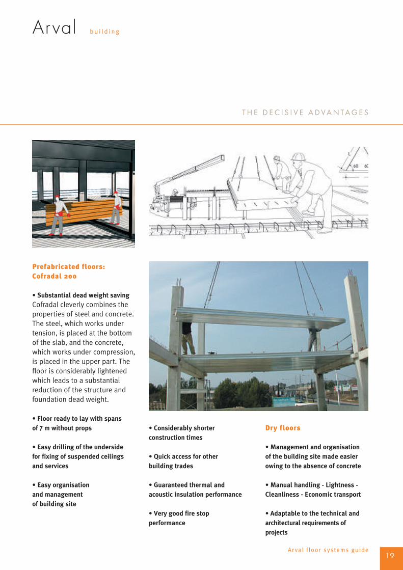
Prefabricated floors:Cofradal 200
• Substantial dead weight savingCofradal cleverly combines theproperties of steel and concrete.The steel, which works undertension, is placed at the bottomof the slab, and the concrete,which works under compression,is placed in the upper part. Thefloor is considerably lightenedwhich leads to a substantialreduction of the structure andfoundation dead weight.
• Floor ready to lay with spansof 7 m without props
• Easy drilling of the undersidefor fixing of suspended ceilingsand services
• Easy organisationand managementof building site
• Considerably shorterconstruction times
• Quick access for otherbuilding trades
• Guaranteed thermal andacoustic insulation performance
• Very good fire stopperformance
Dry floors
• Management and organisationof the building site made easierowing to the absence of concrete
• Manual handling - Lightness -Cleanliness - Economic transport
• Adaptable to the technical andarchitectural requirements ofprojects
Arval bu i l d i n g
r e f e r e n c ep r o j e c t s
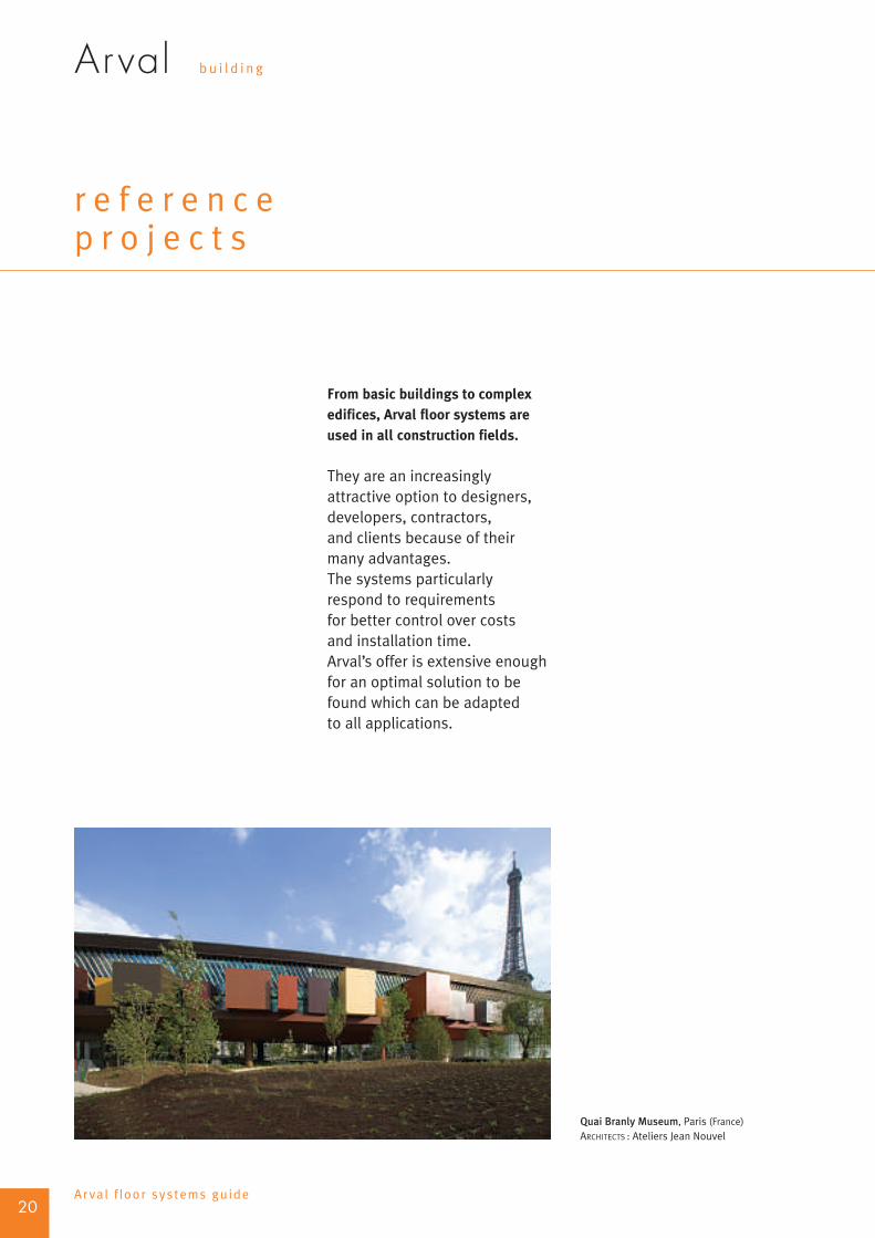
From basic buildings to complexedifices, Arval floor systems areused in all construction fields.
They are an increasinglyattractive option to designers,developers, contractors,and clients because of theirmany advantages.The systems particularlyrespond to requirementsfor better control over costsand installation time.Arval’s offer is extensive enoughfor an optimal solution to befound which can be adaptedto all applications.
20Arval f loor systems guide
Quai Branly Museum, Paris (France)ARCHITECTS : Ateliers Jean Nouvel

Arval bu i l d i n g
Arval floor systems are particularlyvalued for renovation of oldbuildings.
They are therefore often laid inlisted buildings located in largecities as it is possible to changethe layout of the buildingstoreys without increasing costs.The external walls are conservedwhile a new structure takesshape inside the building.
The steel decks that make upthe floor are inserted manuallythrough window openings, andthe great ease of handling makethem the only sensible choice,given that heavy liftingmachines are not possible inthis case.
The reduced dead weightof Arval floor systems comparedto a solid slab is of real benefitwhen the allowable loadson supporting walls andfoundations are limited.The ease of cutting is also veryvaluable in renovation as it ispossible to follow the irregularshapes of walls and to skirtobstacles.
21
R E F E R E N C E P R O J E C T S
■ R E N O VA T I O N
Arval f loor systems guide
Photo on top:
Head office of Crédit Lyonnais, Paris (France)ARCHITECTS: Architecture studio Jean-Jacques Ory
Photo below:
Chaussée d’Auderghem Building,Brussels (Belgium)
Photo on right side:
Hôtel Dieu, Poitiers (France)ARCHITECT: Georges Duclos

R E F E R E N C E P R O J E C T S
Arval bu i l d i n g
This type of constructionis linked to a growing needresulting from the developmentof urban public transport andparticularly commercial centres.The composite steel-concreteproduct line is particularlysuited to the construction of thistype of column/beam structure.
The floor beam spacing of 2,5 m,5 m, 7,5 m or 10 m, correspondsrespectively to 1, 2, 3, or 4 carparking bays, and the deckspans in general are 2,5 m.The span of the beams is from15 to 16 m, and the assemblyallows for large areas clearof columns for parking anddriving.
22
■ E L E VA T E D C A R P A R K S
Arval f loor systems guide
Arval floor systems are used in the constructionof elevated car parks located near airports,shopping centres, hospitals, train stations, etc.
Photo on top:
Car park Carrefour, Aix-les-Milles (France)ARCHITECTS: Sud architectes (Y. Melia)
Photo below:
Car park of Hospital centre, LuxemburgARCHITECTS: Gubbini & Linster

Arval bu i l d i n g
The decks are laid continuouslyand without props.Shear studs are welded to thejoists to create a connectionbetween the slab and the girder.The concrete is taken intoaccount when calculating theinertia of the joists.
This construction procedureis used to reduce the sectionand the floor-space requirementof the joist section.
Arval floor systems avoidthe access problems causedby lifting machinery oncethe steel framework hasbeen laid.
It is a rational, fast, andeconomical form of installation.
23
R E F E R E N C E P R O J E C T S
Arval f loor systems guide
Photo on top:
Car park Hospital centre, LuxemburgARCHITECTS: Gubbini & Linster
Photo below:
Car park Auchan, Amiens (France)ARCHITECTS: Richard Jacques architecture

Arval bu i l d i n g
Depending on the natureof the soil, the constructionprogresses from the lowestlevel (in the case of a strongsoil) upwards, or fromthe highest level downwards(in the case of loose soil).
The ease of handlingof the decks in this caseis a fundamental criteriongiven the difficult of workingwith heavy handling machinery.Their use is essentialparticularly when startingconstruction at the top.
24
■ U N D E R G R O U N D C A R P A R K S
Arval f loor systems guide
Arval floor systems are usedto build underground car park floorsin large cities.
Car park Cité Internationale, Lyon (France)
ARCHITECTS: CRB Architectes
R E F E R E N C E P R O J E C T S

Arval bu i l d i n g
Underground car parks mayhave circular ramps.In this case, the deck endsare cut at a skewed angledirectly in the factory.
In this manner, the decksconnect the inner ringand the outer ring usingreinforced concrete beamspoured on site.
The great adaptability ofArval floor systems to technicaland architectural requirementswork wonders in a scenariosuch as this.
25
R E F E R E N C E P R O J E C T S
Arval f loor systems guide
Photo on top:
Car park Lazare Goujon, Villeurbanne (France)
ARCHITECTS: Demichel & Dordilly
Photos below:
Car park Saint-Georges, Lyon (France)
ARCHITECTS: Cabinet Governor

R E F E R E N C E P R O J E C T S
Arval bu i l d i n g
The overall weight reductionand the savings in steel andconcrete contributed by Arvalfloor systems bring value toall column/beam type structureprojects such as office buildings.
The overall weight of Arval floorsystems is considerably lessthan that of common concreteslabs, and those with integratedthermal and acoustic insulatingproperties offer bettersoundproofing to both airbornenoise and impact noise.
26
■ O F F I C E B U I L D I N G S
Arval f loor systems guide
Espace Pétrusse, LuxemburgARCHITECT: Marc Werner
Stadttor, Düsseldorf (Germany)
ARCHITECTS: Overdiek, Petzinka & PartnerTour Madou, Brussels (Belgium)
ARCHITECTS: Assar/archi 2000

Arval bu i l d i n g
In wide-span office blockswithout intermediate columnsand large clear spaces,the structure and the slabsof composite steel-concreteconstruction are usedto produce low-thickness floorswith reduced beam sections.
The combination of castellatedjoists simplifies the routingof service and reduces the totaldepth of the floors.
27
R E F E R E N C E P R O J E C T S
Arval f loor systems guide
Photo on top:
Le Colisée II, Paris (France)ARCHITECTS: Skidmore, Owing & Merrill ;Architecture et Communication
Photo below:
7 place d’Iéna, Paris (France)ARCHITECTS: Agence d’architectureAnthony Béchu

R E F E R E N C E P R O J E C T S
Arval bu i l d i n g
The robustness of Arval floorsystems makes them suitablefor building floors with heavyand very heavy live loads.
In activity buildings, they havemultiple uses particularly asstorage floors, mezzanine floors,or divider floors.
28
■ A C T I V I T Y B U I L D I N G S A N D C O M M E R C I A L C E N T R E S
Arval f loor systems guide
Mercedes Benz center, Rueil-Malmaison (France)
ARCHITECTS: M. Macary, L. Delamain

Arval bu i l d i n g
The joists are sufficiently closeto be able to dispense withpropping.
Arval floor systems also offergood performance under liveloads for vehicles (e.g. forklifttrucks).
This performance, in conjunctionwith the simple creation of flooropenings, makes them naturallysuited to floors in productionand storage areas.
29
R E F E R E N C E P R O J E C T S
Arval f loor systems guide
Building E. Placenet,Saint-Martin-Boulogne (France)
BET: Maning

R E F E R E N C E P R O J E C T S
Arval bu i l d i n g
Arval floor systems possessall the performancespecifications requiredto divide buildingsinto compartments meetingthe relevant fire, thermaland acoustic regulations.
The Cofradal 200 andSupportsol Décibel floorsystems are particularly idealfor buildings with supportinghollow-brick or cement-blockwalls as a result of theirflexibility of use.
30
■ R E S I D E N T I A L B U I L D I N G S
Arval f loor systems guide
Photo on top:
Villa, Pessac (France)ARCHITECTS: Cabinet Baudin et Limousin
Photo below:
Villa, Villeneuve-lès-Avignon (France)
ARCHITECTS: Patriarche & Co
Arval bu i l d i n g
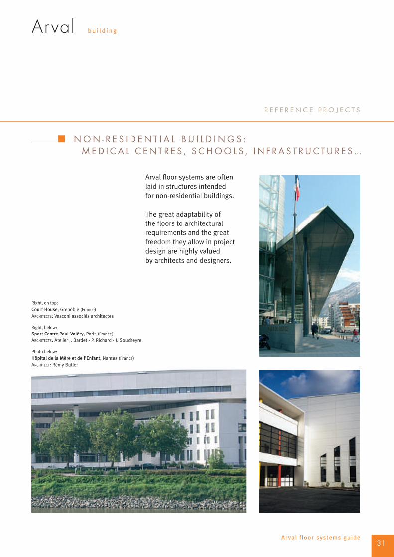
Arval floor systems are oftenlaid in structures intendedfor non-residential buildings.
The great adaptability ofthe floors to architecturalrequirements and the greatfreedom they allow in projectdesign are highly valuedby architects and designers.
31
R E F E R E N C E P R O J E C T S
Arval f loor systems guide
■ N O N - R E S I D E N T I A L B U I L D I N G S :M E D I C A L C E N T R E S , S C H O O L S , I N F R A S T R U C T U R E S …
Right, on top:
Court House, Grenoble (France)
ARCHITECTS: Vasconi associés architectes
Right, below:
Sport Centre Paul-Valéry, Paris (France)ARCHITECTS: Atelier J. Bardet - P. Richard - J. Soucheyre
Photo below:
Hôpital de la Mère et de l’Enfant, Nantes (France)ARCHITECT: Rémy Butler

Arval bu i l d i n g
s u s t a i n a b l ed e v e l o p m e n t
The HQE® initiative brings realadded value to the building andmust therefore be used as a factorto enable the client to differentiateand foster loyalty among theoccupants, which is a challenge forprivate and public rental-housingmanagers.
The HQE® initiative thereforefully contributes to quality, whichhas been a real commercialadvantage for several years.
The Arval floor solutions are alliedto the HQE® initiative.
In this context, whereenvironment, health, andeconomy are increasinglyinterconnected, steel has manyadvantages.
It is recyclable, durable, strong,and also neutral from a healthpoint of view, and thus proveseveryday that it is capable ofmatching the level of the mostinventive and successfularchitectural procedures,and adapting to the mostexacting implementationconditions, particularlywith regard to building-sitenuisance. This potential makessteel an ally of the HQE®
initiative.
The prefabrication of steelconstruction elements in thefactory reduces building-sitenuisance to an absoluteminimum. The excellentweight/strength combinationof Arval floor systems offers avery wide range of architecturalpossibilities and renders lightstructures possible, thus leavinga large area open to lightand harmoniously integratinginto the environment.
Arval floor systems providea multitude of thermal- andacoustic-insulation solutions.Comfort, aesthetics, safety,economy, and resourcepreservation are some ofthe many qualities of steelconstruction and the manyadvantages in relation to theHQE® initiative.
Low thermal inertia
Arval floor systems leadto buildings with low thermalinertia.
Energy is therefore not wastedin heating the structures.It is also possible to regulateheating needs with a certainamount of flexibility according
to the hours that the buildingis occupied. This is anadvantage for offices at night-time, and houses during thedaytime.
Furthermore, it has alreadybeen demonstrated that it ispossible to construct buildingsfor daytime occupation withoutthe need for a heating system,by relying on strengthenedinsulation and drawing onthe heat of the sun duringthe day.
Preservation of resources
The natural mechanicalcharacteristics of steel(particularly a highstrength/weight ratio)enable structures supportinglight floors to be createdin order to gain living space.The minimal depth of the floorsystems limits the consumptionof raw materials and energy.
The low weight of steelconstructions is alsoadvantageous on weakground, which would requiresubstantial foundationsto bear traditional buildings.
32
■ T H E H I G H E N V I R O N M E N T A L Q U A L I T Y I N I T I A T I V E
Arval f loor systems guide

Arval bu i l d i n g
33
H I G H E N V I R O N M E N T A L Q U A L I T Y
Arval f loor systems guide
Flexible and adaptable
Sustainable developmentis concerned with the needsof future generations.Arval floor solutions makeit easy to remodel spacesaccording to changesof use and changes to familystructures, while reducingenvironmental impact(e.g. waste, energyconsumption).
These solutions allowfor renovations suchas extensions, rehabilitation,or adapting to new/changedregulations (e.g. strengtheningor adding a stair well).
Integrated choiceof construction proceduresand systems
This is probably the areaof the HQE® initiative wherethe contribution of steelis most tangible.
The reason for this is thatArval systems participatein this resource-saving logicby fulfilling the requiredfunctions with reducedconsumption of raw materials.
Recyclable and recycledmaterial
Steel can be 100% recycledindefinitely, without anyalteration to its qualities.It has unequalled magneticproperties that enable itto be separated and recoveredfrom waste of any kind.The percentage of steelproduction worldwide resultingfrom recycling scrap is 40%.The same applies to preservedore (even though iron ore is oneof the most abundant elementsin the Earth’s crust), resultingin reduced energy consumptionand therefore greenhouse-gasemissions.
Durable material
With metal coating (galvanising)and/or paint systems to protectagainst corrosion, steel retainsits properties over the entirelifetime of the structure andensures its longevity.Steel ductility is also a majoradvantage against earthquakes.The damage suffered bystructures subject toearthquakes is minimised, therisk of collapse is eliminated,and human life is saved.

Arval bu i l d i n g
h o w t o c h o o s e t h e m o s ts u i t a b l e s y s t e m ?
• Service floors– industrial production buildings– commercial buildings– elevated and undergroundcar parks
– warehouses
• Compartment floors– office buildings– collective and individualhousing
– health and leisure homes,hospitals
– schools– renovations
Choice guide
The best solutions mustbe chosen accordingto the problem posed,and the technicaland economic constraints.
The “Common solutionschoice guide” is a quick searchaid for the Arval floor systemmost suited to the projectrequirements.
The Arval sales and technicalassistance teams are at yourdisposal to help you choosethe best solution for yourproject and the associatedspecifications.
34Arval f loor systems guide
Arval floor systems stand out forthe advantages they offer in termsof reduced weight, speed ofinstallation, cost savings, andresistance in the most variedapplications where they are employedas a natural complementto the framework.
On site concrete pouring of the slab
Installation of a prefabricated floor

Arval bu i l d i n g
35
H O W T O C H O O S E
Arval f loor systems guide
The following chapter Designing permits to optimise the choice according to the specifications.
Béton etmaçonnerie Métallique Bois
Industriels Cofrastra Cofrastra Cofrastra
Entrepôts Cofraplus, Cofrasol Cofraplus, Cofrasol Cofraplus, Cofrasol
Bureaux Cofrastra, Cofradal 200 Décibel Cofrastra, Cofradal 200 Décibel
Cofraplus, Cofrasol, Cofradal 200 Cofraplus, Cofrasol, Cofradal 200
Enseignement Cofraplus, Cofrastra Cofraplus,
Cofrasol, Cofradal 200 Cofrasol, Cofradal 200
Santé Cofraplus, Cofrastra Cofraplus, Cofrastra
Cofrasol, Cofradal 200 Cofrasol, Cofradal 200
Infrastructures Cofraplus, Cofrastra Cofraplus, Cofrastra
collectives Cofrasol, Cofradal 200 Cofrasol, Cofradal 200
Centres Cofraplus, Cofrastra Cofraplus, Cofrastra Cofraplus, Cofrastra
commerciaux Cofrasol, Cofradal 200 Cofrasol, Cofradal 200 Cofrasol, Cofradal 200
Logementscollectifs Cofrastra Décibel, Cofrastra Décibel
Cofradal 200, Supportdécibel Supportdécibel
Logements Cofrastra 40 Cofrastra 40 Cofrastra 40
individuels Cofraplus, Cofradal 200 Cofraplus, Cofradal 200 Cofraplus 60, Cofradal 200
Réhabilitation Cofrastra 40, Cofraplus Cofrastra 40, Cofraplus Cofrastra 40, Cofraplus
Cofrasol Cofrasol Cofrasol,
Parkings Cofraplus, Cofrastra 70 Cofraplus, Cofrastra 70
Cofrasol Cofrasol
Béton etmaçonnerie Métallique Bois
Constructions Cofrastra 40 Cofrastra 40
modulaires Cofratherm Cofratherm
Planchers Supportsol Supportsol
secs Supportdécibel Supportdécibel
Toitures Cofrastra 40, Cofradal 200 Cofrastra 40, Cofradal 200 Cofrastra 40, Cofradal 200
terrasses Cofrasol Cofrasol Cofrasol
BâtimentsStructure
DestinationStructure
Common solutions choice guide
Cofradal 200, Supportsol Décibel
Logements
collectifs Supportsol Décibel
Supportsol Décibel Supportsol Décibel
Buildings
Industrial Buildings
Warehouses
Office
Schools
Medical Centres
Collective
Infrastructures
Commercial
Centres
Collective
Housing
Individual
Housing
Renovation
Car Parks
Modular
Construction
Dry floors
Flat roofs
Use
Concrete and Masonry Metal Wood
Concrete and Masonry Metal Wood

Designing
Arval
36Arval f loor systems guide

Sport City Tower, Doha (Qatar)
ARCHITECT: Concept Architect
Hadi Simaan, Florida (USA)
STRUCTURE: Arup, London
(United Kingdom)
Arval
37Arval f loor systems guide

Arval d e s i g n i n g
A r v a l f l o o r s y s t e mf r a m e s
The spacing of the mainconcrete or steel beams andjoists, which is generallyadjustable, varies from1,5 to 7 m according to therequirements of the project.The span of beams or joistscan reach 18 m or more.
The choice of spans and spacingof the beams and joists isoptimised for economyaccording to the project data.
For each frame desired, there areone or more Arval floor solutionssuitable for the building-siteconstraints, the assemblyrequirements, and the overall cost.
Arval uses its globalFloorsoftware to optimise the beamand slab interaction to identifythe most economical solution.
Designers generally preferto reduce the spacing betweenjoists or beams to avoid havingto use propping when laying.The limited unpropped spanand the required slab thicknesscan therefore be used to guidesolution selection.For most applications, theimposed load is not a limitingfactor in floor design.
Our design software facilitatesthis economical and technicalchoice.
These points are illustratedwith the help of some examplesof general construction projectswhere an Arval floor systemadapted to the specific projectdata has been selected.(pages 61, 62 and 63)
38Arval f loor systems guide

Arval d e s i g n i n g
p e r f o r m a n c e o f A r v a lf l o o r s y s t e m s
39Arval f loor systems guide
Maximum admissible spans without propping in construction stageUniformly distributed loads, equal double span slab and deck, thickness 0,75 mm
Cofraplus 60 Cofraplus 77 Cofrastra 40 Cofrastra 70
Span 3,60 m 4,19 m 2,65 m 3,73 mLine of props 0 0 0 0Mimimum slabdepth 10 cm 12 cm 8 cm 11 cm
Span 2,14 m 2,62 m 1,95 m 2,05 mLine of props 0 0 0 0Maximum slabdepth 28 cm 28 cm 20 cm 30 cm
Concrete saving and savings relating to the weight of composite slabscompared to solid slabs
Composite deck Concrete saving Resultant saving Range of dead weight saving in %litres/m2 resulting in deadweight for a slab thicknessfrom the ribs space compared to a solid slab from composite slabon the underface of equivalent minimum thickness
depth kg/2 to 20 cm
Cofrastra 40 10 24 8 to 20 cm 12 to 5%
Cofrastra 70 24 58 11 to 20 cm 22 to 12%
Cofraplus 60 35 84 10 to 20 cm 35 to 18%
Cofraplus 77 44 105 12 to 20 cm 37 to 22%

P E R F O R M A N C E S O F A R VA L F L O O R S Y S T E M S
Arval d e s i g n i n g
40Arval f loor systems guide
Reinforcement saving achieved by composite slabsExample of comparison
Fire rating 30 minutes
Imposed loads: 3,5 kN/m2, 8 kN/m2, 15 kN/m2
Equal double span slab, span 3 m
Deck thickness : 0,75 mm
Span (m) Reinforcement savingin comparisonwith a solid slab
Imposed loads 3,5 kN/m2
Floor process Solid slab Cofraplus 60
Slab depth 10 cm 10 cm
Flexural Reinforcement 2,24 kg/m2 / 2,24 kg/m2
Imposed loads 8 kN/m2
Floor process Solid slab Cofraplus 60
3 Slab depth 11 cm 12 cm
Flexural Reinforcement 3,73 kg/m2 / 3,73 kg/m2
Imposed loads 15 kN/m2
Floor process Cofrastra 70
Slab depth 13 cm 12 cm
Flexural Reinforcement 5,2 kg/m2 / 5,2 kg/m2
Solid slab

Arval d e s i g n i n g
41
P E R F O R M A N C E S O F A R VA L F L O O R S Y S T E M S
Arval f loor systems guide
Fire stop solutionsSuspended ceilings - Cofrastra Décibel floor without fire-bracing reinforcement bars
Fire stop Special measures References
30 minutes None Technical approval
Fire stop ceiling60 and 90 minutes Placoflam® BA13 CSTB Report Nr. 93.36105
Placoplatre
Fire stop ceiling120 minutes Placoflam® BA15 CSTB Report Nr. 93.36105
Placoplatre
Arval floor system Cofraplus, Cofrastra, Cofradal, Cofrasol performancesFire stop criteria, acoustic, punching of holes for passage of workshop-welded shear studs fixing of suspended ceilings
Cofraplus 60 Cofraplus 77 Cofrastra 40 Cofrastra 70
Fire stop 30 minutes without fire- 30 minutes without fire- 30 minutes without fire- 30 minutes without fire-bracing rebar. Up to 3 hours bracing rebar. Up to 3 hours bracing rebar. bracing rebar. Up to 3 hours
with fire-bracing rebar with fire-bracing rebar Up to 3 hours with fire reinf. with fire-bracing rebar
Acoustic ** ** **/*** **/***Cofrastra Décibel Cofrastra Décibel
Punching of holes forthe passageworkshop- Yes Yes Yes Yeswelded shear stud
Fixing of suspended Drilling Drilling Cofrafix or drilling Cofrafix or drillingceilings
Cofradal 200 Cofrasol
Fire stop 30 minutes without fire- 30 minutes without fire-bracing rebar. 2 hours and bracing rebar. Up to 3 hoursmore with fire-bracing rebar with fire-bracing rebaraccording spans and loads according spans and loads
Acoustic *** **
Punching of holes forthe passageworkshop- Not necessary Nowelded shear stud
Fixing of suspended Drilling Drillingceilings

Arval d e s i g n i n g
c o m p l i a n c eo f A r v a l f l o o r s y s t e m sw i t h r e g u l a t i o n s
42Arval f loor systems guide
The design, dimensioning andcalculation of Arval flooringsystems are carried out inaccordance with the regulationsas laid down in each individualcountry.
In France for example, theCofraplus, Cofrastra andCofradal 200 composite floorsare subject to the CSTB
In Germany, composite flooringhas been given a Zulassunggranted by the Buildingauthorities (DIBt in Berlin).
They satisfy the regulatory framework for each typeof utilisation. Arval floor systems use factory manufacturedindustrial components. Their constant reliability and qualityare obtained through systematic and rigorous internalinspection by the manufacturer.
Technical Assessment procedure.

Arval d e s i g n i n g
43
C O M P L I A N C E S W I T H B U I L D I N G R E G U L A T I O N S
Arval f loor systems guide
The dimensioning and calculation of Arvalflooring is, moreover, carried out as perEurocodes and completed by National Annexesfrom each country. Eurocodes are the keyto the development of modern buildingtechniques in Europe and some countriesare already applying them.
An example, that is not exhaustive, is that Arvalcomposite flooring, as used in Belgium andPoland, is covered by a Technical Approval thatmeets the dimensioning requirements as laiddown in Eurocode 4 « Calculation of combinedsteel-concrete structures».
Results of tests carried out and validatedin different situations help to designand dimension Arval flooring :- loading and strength testing,- tests on shear connectors,- and fire resistance testing.
Floor deck testsConstruction stage
Composite slab testsComposite stage

Arval d e s i g n i n g
d e s i g nc r i t e r i a
Floor thickness
The floor thickness affectsthe height of the working floorin situations where thereis a limitation on the heightof the building.
The minimal thickness of Arvalfloor systems for imposed loadsfrom 2.5 kN/m2 to 10 kN/m2
enables the floor spacerequirement to be reducedas much as possible.
Cofrastra 40 is therefore usedto design shallow slabs of 8 cmfor spans of up to 2.6 m andimposed loads up to 3.5 kN/m2.
It is possible to design floorswith reduced floor spacerequirement by combiningArval floor systems with beams,ACB castellated beams (beamswith round holes in the core)or IFB/SFB asymmetric beams.
As a result of their wider bottomflang, these beams areparticularly suited to laying floorsystems such as Cofradal 200and Supportsol Décibel floors,which enables them to beintegrated into the heightof the beam thus eliminatingthe under-floor sections.
44Arval f loor systems guide

Arval d e s i g n i n g
Deflection
• Deflection criteria duringthe construction stage.The deflection during theconstruction stage is limitedby the regulations.Eurocodes:L/180, where L equals the span.The effect of increasing theweight of the concrete owingto deflection is taken intoconsideration when calculatingthe weight of the wet concreteif the deflection is higher than1/10 of the slab depth.France:The effect of increasingthe weight of the concreteowing to deflection is taken intoconsideration when calculatingthe weight of wet concrete.
Arval recommends limitingdeflection to L/300 for bettervisual appearance.
• Deflection criteria during thecomposite stage under normal loads.Cofraplus, Cofrastra,Cofradal 200Eurocodes:Eurocode 2 recommends notto exceed a deflection higherthan L/250 and to establishthe appropriate limiting values,taking into account the natureof the structure, the finishes,partitions and fixings and uponthe function of the structure.France:Slabs not supporting brickworkpartitions or fragile floor coatingsSpan L ≤ 3,5 m, f ≤ L/350Span L>3,5 m, f ≤ 0,5 cm + L/700
Slabs supporting brickworkpartitions or fragile floor coatingsSpan L ≤ 5,0 m, f ≤ L/500Span L>5,0 m, f ≤ 0,5 cm + L/1000
Supportsol, Cofratherm,Supportsol Décibelf ≤ L/300
Natural frequency
The Arval technical assistanceteam examines particularrequirements of naturalfrequency on request.
45
D E S I G N C R I T E R I A
Arval f loor systems guide
I Beam
Castellated beam ACB
IFB
globalFloor

D E S I G N C R I T E R I A
Arval d e s i g n i n g
Anti-crack mesh
It is necessary to introducea mesh into self-supportingslabs and composite slabsto absorb the forces causedby drying of the concrete duringcuring.
It reduces and distributescracking. The mesh is laid 2 cmfrom the top of the slab.The mesh, on stools,acts as a support for anytop reinforcements andcontributes to the resistanceagainst negative moments.
Top reinforcements
As with traditional reinforcedconcrete slabs, topreinforcement on intermediatesupports is necessary to absorbnegative moments wherecontinuity is taken into accountand/or where a fragile floorcoating is expected.
These reinforcements,preferably in the form of meshor rebars connected to thegeneral mesh, cover a minimumarea of at least 0,3 timesthe span L, from one endof the support to the other.
46Arval f loor systems guide
The different reinforcementsections in the followingparagraph are dimensioned by
which is available on request.
■ R E I N F O R C E M E N T
Treillis soudé antifissuration
using Cofra design software

Arval d e s i g n i n g
Load-distribution mesh
This is a second mesh usedin projects where there aremobile and/or localised loads.It is used to distribute theseloads and transmit the forcesto the supports.The load-distribution meshis keyed to the rib crownsto ensure that the barsare covered.However, this keying is notnecessary if the deck/barcontact is in one spot in relationto the shape of the ribs.
Fire-bracing reinforcementbars
Arval composite floors providenatural fire resistance for30 minutes.If more than 30 minutes of fireresistance is required, it isnecessary to adjust performanceby adding fire-bracing rebarsplaced into the ribs.
Flexural reinforcement bars
These are rebars placed intothe ribs. Their role is to providestrength against bending(resistance or deflection)where the steel sectionprovided by the compositedeck is insufficient.
Vertical shear strengthreinforcement bars
If the vertical shear strengthis greater than the admissiblevertical shear strength, it ispossible to add reinforcementbars into the ribs, anchoredto a support.These arrangements are onlydesigned for the end-bays.
47
D E S I G N C R I T E R I A
Arval f loor systems guide
Anti-crack meshLoad-distribution mesh
U variable
Gravity centre

D E S I G N C R I T E R I A
Arval d e s i g n i n g
Arval floor systems can be easilyused on steel, concrete, andwood joists and beams, and alsoon brickwork (load-bearingwalls).
48
■ S U P P O R T S S T R U C T U R E S
Arval f loor systems guide
Decking on steel beam
Decking on steel beam
Decking on steel beam Decking on steel beam
Decking on brickworkDecking on wood beamDecking on concrete beam

Arval d e s i g n i n g
49
D E S I G N C R I T E R I A
Arval f loor systems guide
■ L AY I N G M E T H O D S
Continuous layingThe decks are laid over severalcontinuous bays. This layingarrangement, known as‘continuous’, creates acontinuous formwork over thewhole building, with each deckcovering twoor more bays.Advantages:
Faster laying
Larger spans without props
Laying with rebatesThe decks form a non-continuous formwork, as theystop over each beam. Each deckcovers one bay. It rests on asingle supportat each end.Advantages:
Easier to hand-carry
Easier laying
Continuous laying and laying with rebates
Continuous laying on steel beam
Continuous laying on steel beam withconnectors
Continuous laying on concrete beamwith non-welded connectors
Continuous laying on concrete beam
Laying with rebates on concrete beam

D E S I G N C R I T E R I A
Arval d e s i g n i n g
50
■ S T E E L G I R D E R I N G
Arval f loor systems guide
The laying of decks on steel beamsequipped with shear connectorsis possible.Connectors make it possible toform a steel-concrete compositebeam and to optimise thesupporting structure.
The connectors are designedto create a link betweenthe reinforced concrete slaband the steel beam to createa composite structure. Their roleis to transmit the horizontalshear forces acting betweenthe structure and the concreteslab. The laying and the numberof connectors arranged alongthe composite beam areestablished by design.
There are two connector typesavailable:Welded shear studs:
The shear studs are weldedonto the steel beams eitherin the workshop oron the building site.Non-welded connectors:
These are L-shaped cold-formedmetal pieces fixed to the beamusing two nails shot fireddirectly into place using acartridge-operated fixing device.
Advantages• Important savings in steel weight
• For equivalent span and load values,
this procedure substantially reduces
the dimensions of steel beams.
• A considerable height saving
• This procedure reduces floor
thickness and results in a saving
in floor space that can be used
to create extra storeys.
• Smaller surface areas to paint
or flock
• Increased rigidity of the construction
and better seismic stability
• If the height of the steel beams
is restricted: gain in span (larger
joist spacing).
Non-welded connectors
Fixing by nails
Concrete grade 25 minimum

Arval d e s i g n i n g
Additional advantagescontributed by Cofraplusand Cofrastra in caseof welded studs:• they can be delivered prepunched
in factory on request, which saves
a lot of time and the connectors
can be welded in the best conditions
in workshop.
51
D E S I G N C R I T E R I A
Arval f loor systems guide
E x a m p l e 1
Data• Cofraplus 60 composite deck,0,75 mm• Double span slab 3.0 m• Imposed load: 3.5 kN/m2,permanent load: 0.75 kN/m2
• Steel framework:beam spans 14 mDesign calculation made using
globalFloor software
Design calculation results• Beams without connectorsIPE 600 beams, weight 122 kg/ml
• Composite beam with connectorsIPEa 500 beams,weight 79.4 kg/ml
Saving with connectors• Beam weight: 42.6 kg/ml,or 35%
• Beam height: 100 mm,or 16.6 %
• Beam protection (paint,flock): 7%
E x a m p l e 2
Data• Cofraplus 60 composite deck,0.75 mm• Double span slab• Imposed load: 3.5 kN/m2,permanent load: 0.75 kN/m2
• Steel framework:beam spans 14 m• IPE beams with height of 600 mm
Design calculation made using
globalFloor software
Design calculation results• Beams without connectorsSlab span (joist spacing): 3.0 m
• Composite beam with connectorsSlab span (joist spacing): 4.3 m
Saving with connectors• Slab span: 1.3 m, or 43%
Welded stud

Arval d e s i g n i n g
52Arval f loor systems guide
The system can be usedin concrete frame constructionwith reinforcement barsprepared to receive the deckingand slab.The decks are laid by rebating.
Advantages
• A considerable saving in concrete
weight
• For equivalent span and load
values, this procedure substantially
reduces the dimensions of concrete
beams.
• A substantial height saving
• This procedure reduces floor
thickness and leads to a usable
floor space gain through
the addition of extra storeys.
• If the concrete beam height
is restricted:
There is a gain in span (larger
beam spacing)
■ C O N C R E T E F R A M E S
D E S I G N C R I T E R I A
Rebate laying
Rebate laying on fixedangle brackets
Continous layingThe connections fixed using nails shot firedpermit a continous laying on concrete beam.

Arval d e s i g n i n g
Floor-opening can be easilycreated with Arval floors.
Floor-opening of smalldimensions
Floor-opening box-outs of 50 cmx 50 cm maximum, preparedbefore casting the concrete, canbe created using sheetformwork delivered in therequired dimensions, by woodenshutter, or by polystyrene block.In this case, the sheet is only cutonce the concrete has hardened.
They are reinforced by fixing 50x 50 x 5 mm corner beams toand in the direction of the ribsfrom one end of the opening tothe other.
There is no need to fitreinforcement if only one rib iscut. If two or three ribs are cut,the lost steel section can becompensated by bars arrangedacross the opening.
Larger floor openings
In the case of larger flooropenings, it is necessaryto fit additional structuralelements (trimmers).
A floor-opening system madeup of transverse andlongitudinal angle trims andbearers canalso be used. This system,which is integrated into the slab,serves as a trimmer andreinforces the slab aroundthe opening. The differentcomponents of the systemcan be delivered in the requireddimensions.
53
D E S I G N C R I T E R I A
Arval f loor systems guide
■ F L O O R O P E N I N G S

Arval d e s i g n i n g
f i r eb e h a v i o u r
• Arval floor systems complywith regulations relating to firesafety.
• The concrete-steelcombination provides efficientprotection against risingtemperatures and Arval floorshave a natural fire stability of 30minutes.
• In case of fire, the steel decksprevent the concrete frombreaking up and the slab fromcollapsing.
• The duration of fire resistancecan be economically increasedup to 2 hours by usingadditional reinforcements in theconcrete within the ribs. In thecase of Arval floor systems,the result is always a smallerreinforcement section thanis required for solid slabs usingidentical design assumptions.
54Arval f loor systems guide
U variable

Arval d e s i g n i n g
• The fire-bracing reinforcementsection and its positioning inthe ribs is established by designin application of Eurocode 4.
• These fire-bracing rebarscan also serve as cold-flexuralrebars.
• The fire resistancerequirements also determinethe thickness of the slab.
• The fire-resistance durationcan also be increased to 2 hoursby adding suspended fire-stopceilings.
• For fire-stop rating greaterthan 2 hours, it is usuallypreferable to use protectionsprayed on the underside asit is more economical.
• The fire-stop ceilingprocedures and sprayedprotection provide fire stabilityto the beams and sparefire-bracing reinforcements.
• Arval floors combined withsteel joists have been subjectto special fire-resistance teststo validate the behaviour ofthe joist-beam interaction(CTICM Test-Reports).
55
F I R E B E H A V I O U R
Arval f loor systems guide

Arval d e s i g n i n g
a c o u s t i cb e h a v i o u r
56Arval f loor systems guide
Sound insulation
Sound insulation of wallsuses two principles:• The law of mass, whichgoverns acoustic behaviourof homogeneous walls suchas concrete slabs.• The law of mass-damping-mass, which guides the acousticbehaviour of non-homogeneouswalls such as Cofrastra décibel,Cofradal 200, Cofradal 200décibel, and Supportsol décibelfloor systems.
The acoustic behaviourof Cofrasol, Cofraplus,and Cofrastra correspondsto the law of mass.These Arval floor systemshave a sound reduction index,which is proportional to theirmass. These floors havecharacteristics similar to a solidslab with a thickness equivalentto the average floor thickness.
It is possible to use Arval floorsystems governed by the lawof mass-damping-mass toobtain superior insulationperformance.
Airborne noise insulation(e.g. voices, television, stereo)is therefore obtained usingsystems combining the slabwith a floating screed anda sound-insulation materialunder the screed laid at the topof the slab, or a suspendedceiling: plasterboards andsound insulation material in theplenum space, such as CofrastraDécibel.
With regard to impact-noisereduction, effectivenessis obtained by combiningeither of the two systemsdescribed above with a resilientfloor covering (e.g. carpetsor plastic flooring).En
ergy
absorbed
WALL
Energ
y emited
S A+B+C
Energy reflected
Energytransm
itted
A
C
B

Arval d e s i g n i n g
Acoustic correction
Cofradal 200 DécibelThe underside of Cofradal 200 trays can be perforatedto meet acoustic-correction requirements.The absorption coefficient αw is 0.85.
57
A C O U S T I C B E H A V I O U R
Arval f loor systems guide
Acoustic performanceof Cofradal 200 floor system
Complex Rw(C;Ctr) Ln,w CSTB Report
Cofradal 200 only 58 (-1;-6) dB 78 dB ID structuresAC 04-060
Cofradal 200 with suspended ceiling + glass wool PAR 30 mmfrom Isover + BA13 from Placoplatre 64 (-2;-7) dB 66 dB AC 01-133
Cofradal 200 with flooting screed + Rocksol 501, 20 mm + dryreinforced screed of 50 mm 72 (-6;-14) dB 49 dB ID structures
AC 04-060
Acoustic performanceof the Cofrastra 40 Décibel floor system
Complex Rw(C;Ctr) Ln,w CSTB Report
Cofrastra 40 + slab thickness 140 mm 51 (-3;-7) dB 79 dB 23268
Cofrastra Décibel, Cofrastra 40 + slab thickness 140 mm+ plénum space 70 mm + plasterboard BA13 56 (-6;-11) dB 66 dB 23268
Cofrastra Décibel, Cofrastra 40 + slab thickness 140 mm +plenum space 70 mm + IBR 60 mm + plasterboard BA13 65 (-4;-10) dB 61 dB 23268

Arval d e s i g n i n g
t h e r m a li n s u l a t i o n
58Arval f loor systems guide
Thermal insulation under screed Thermal insulation over ceiling
Arval proposes differentsolutions to deal with thermalinsulation decking problems,taking into account the thermalinsulation regulations: inserta thermal insulation underthe screed or insulation overceiling.
The choice of suitable materialsand their laying conditionstakes into account the thermaland insulation regulations(in France: RT 2005).

Arval d e s i g n i n g
59
T H E R M A L I N S U L A T I O N
Arval f loor systems guide
Cofrastra Décibel
If a thermal and/or acoustic insulationmaterial is present in the plenumof the Cofrastra Décibel system, this givesthe floor thermal resistance at least equalto the performance of the quilt or boardused.The thermal exchange between premisesone on top of the other is therefore slightlyreduced, which gives users real freedomto regulate their own heating andto manage their energy costs.
Cofradal 200
The presence of a 130 mm rock-woolpanel (R = 3.14 m2K/m2), gives theCofradal 200 floor excellent thermalinsulation.
Cofrastra DécibelA floor thickness of 20 cm, 4 combinations of slab thickness and insulation material
and their thermal insulation performance
Thickness Thickness Thermal Thermal Coefficientof the composite of the thermal resistance resistance of surface loss
slab insulation material of the insulation of the floor of floor U
8 cm 12 cm 3 m2K/W 3,3 m2K/W 0,31 W/m2K
10 cm 10 cm 2,5 m2K/W 2,8 m2K/W 0,36 W/m2K
12 cm 8 cm 2 m2K/W 2,3 m2K/W 0,44 W/m2K
14 cm 6 cm 1,4 m2K/W 1,8 m2K/W 0,56 W/m2K

Arval d e s i g n i n g
u s e i n s e i s m i ca r e a s
The Cofraplus, Cofrastra,and Cofradal 200 compositesteel-concrete floor systemsin particular, given theirlightness and wide bandof plasticity, offer a notableadvantage in relationto seismic stress comparedto an equivalent reinforced-concrete slab.
They are therefore valued andcommonly used in constructionprojects located in seismicareas.The contribution of compositefloors to the structure’shorizontal bracing (horizontalforce) is also frequently used.
In this application, Cofraplus,Cofrastra, and Cofradal 200are fixed on all supportsand an appropriate numberof connectors are arrangedin the supports. This numberis decided according to thestresses to be transferred.
60Arval f loor systems guide

Arval d e s i g n i n g
e x a m p l e so f d e s i g n
61Arval f loor systems guide
W a r e h o u s e
Data• Loads:Imposed load: 15 kN/m2
Permanent load: 2 kN/m2
• Fire stop: 120 minutes
Frame• Beam spacing: 4,5 m
• Beam spans: 10 m
Proposed solution:The Cofrastra 70 floor
was selected
F l a t s
Data• Loads:Imposed load: 1,5 kN/m2
Permanent load: 1,5 kN/m2
• Fire stop: 120 minutes
Frame• Beam spacing: 5 m
• Beam spans: 5 m
Proposed solutions:Two floors were selected:
- Cofrastra 40 floor: propped
- Cofradal 200 floor: unpropped
E l e v a t e d c a r p a r k
Data• Loads:Imposed load: 2,5 kN/m2
Permanent load: /
• Fire stop: 90 minutes
Frame• Beam spacing (columns) : 2,5 m
• Beam spans: (distance between
building faces) : 16 m
Proposed solution:The Cofraplus 60 floor system
was selected

Arval d e s i g n i n g
62
E X A M P L E S O F D E S I G N
Arval f loor systems guide
O f f i c e s 1
Data• Loads:Imposed load: 3,5 kN/m2
Permanent load: 1 kN/m2
• Fire stop: 120 minutes
Frame• Open-plan floorswith no intermediate columns
• Beam spacing:
• Beam spans (distancebetween building faces) : 14 m
Proposed solution:- Cofraplus 60 floor (3 m span)
- Cofradal 200 floor (6 m span)
O f f i c e s 2
Data• Loads:Imposed load: 3,5 kN/m2
Permanent load: 0,75 kN/m2
• Fire stop: 120 minutes
Frame• Beam spacing: 3 m
• Beam spans: 12 m
• Required floor space withbeam springing: maximum 700
mm including routing of
networks
(i.e. electrical, water, ventilation)
Proposed solution:The Cofraplus 60 floor was
selected in combination with
ACB castellated beams
to enable routing of networks
S c h o o l b u i l d i n g s
Data• Loads:Imposed load:
2,5 kN/m2
4 kN/m2 (for circulation)
Permanent load: /
• Fire stop: 90 minutes
Frame• Beam spacing: 5 m
• Beam spans: 10 m
• Solives : IFB asymmetric beams
Proposed solution:The Cofradal 200 floor
was selected
3 or 6 m

Arval d e s i g n i n g
63
E X A M P L E S O F D E S I G N
Arval f loor systems guide
H o t e l s
Data• Loads:Imposed load: 2,5 kN/m2
Permanent load: 1 kN/m2
• Fire stop: 90 minutes
Frame• Beam spacing: 3 m
• Beam spans: 7 m
Proposed solution:The Cofraplus 60 floor
was selected
H o s p i t a l s
Data• Loads:Imposed load:
1,5 kN/m2
2,5 kN/m2 (for circulation)
3,5 kN/m2 (technical areas)
Permanent load: 1 to 3 kN/m2
• Fire stop: 90 minutes
Frame• Beam spacing: 5,5 m
• Beam spans: 8 m
Proposed solution:The Cofradal 200 floor
was selected
F l a t r o o f
Data• Loads:Imposed load: 2,5 kN/m2
Permanent load: 30 kN/m2
(soil for garden roof )
• Fire stop: 90 minutes
Frame• Beam spacing: 3 m
Proposed solution:The Cofraplus 70 floor
was selected
• Beam spans: 5 to 10 m

CalculatingPresentat ion of Arval design tools and economic compar isonof the var ious solut ions
Arval
64Arval f loor systems guide

Arval
65Arval f loor systems guide

Arval c a l cu l a t i n g
s o f t w a r e
design program for Cofraplusand Cofrastra composite slabs,which was developed by Arval.This software can be installedon request onto your computersystems.
Arval provides TechnicalAssistance for its partners inorder to ensure the completionand technical verificationof flooring projects.
Design assumptions(regulations accordingto the french TechnicalApproval)
• Deflection criteria in the
construction stage:
f=L/240• Deflection criteria in the composite
stage under normal loads:
L ≤ 3.5m f=L/350L >> 3.5m f=0.5 cm+L/700
• Yield stress of steel reinforcement:
σe ≥ 500 MPa• Yield stress of steel deck:
The yield stress of Cofraplus,Cofrastra and Cofradal isbetween 320 and 350 MPadepending on the profile.• Design values of actions:
Permanent loads: 1.35Variable loads: 1.50
Supporting designcalculations
In application of the designrules described in theaddendum to the TechnicalApproval concerning France, orin application of the regulationspertaining to each country inrelation to the project data,supporting design calculationsmay be established by Arval
Cofradal 200
Supporting design calculationsmay be established usingspecial design software.A layout drawing softwareis also used for the slab layoutof Cofradal 200.
66Arval f loor systems gu ide
C o f r a
Cofra is a computer-aided
using the Cofra software.

Date entry
Users can enter the projectsource data from the structure-support drawings intothe program:
• static system: numberof concrete bays and deckbays,
• span of each bay,• maximum number of propsin the construction stage,
• permanent loads and liveloads distributed uniformly,
• requested fire stop duration,• sound reduction,• construction and compositestage deflections,
• load per bay (uniform, linearloads, additional dead loads),live loads (forklifts, cars),
• usage preferences: deck type,deck thickness,
• desired slab thickness,• if the slab is continuous,choose between a singlemesh (optimises laying)and two mesh layers(optimises reinforcementconsumption)
Outcome:
for the minimum slab thicknessrequired according to the designrules described in theaddendum to the TechnicalApproval (if in France) or thosespecified in the Approvalpertaining to each country.
A complete description is drawnup for each solution(reinforcements, concrete, etc.).The description relating to eachsolution is displayed graphicallyon the computer screen.The user can then changeparameters to reach an“optimised” solution. It is alsopossible to print the completedesign calculations.
Arval c a l c u l a t i n g
67Arval f loor systems guide
C O F R A S O F T WA R E
The Cofra software searches
Arval c a l cu l a t i n g
g l o b a l F l o o rs o f t w a r e
globalFloor is a comparative pieceof software that economicallyoptimises flooring using beamsand Arval flooring systems.
It enables frame dimensionsto be selected to achievethe most economic solutiontaking into account the projectconstraints.The components choiceof the globalFloor decking,pre-dimensioning andcomparison of variantsto optimise economic selection,can be chosen from thepre-project stage.
globalFloor is used to specify allselection criteria in conformitywith the French TechnicalApprovals, the Approvalsof other countries, and withthe Eurocodes (in the caseof beams).
It is easy to use and can beconfigured by the user totheir own requirements.
However, this predimensioningtool does not dispense withthe need for a traditionaltechnical study andits corresponding designcalculations.
globalFloor takes into account:
• requirements: building type,imposed and permanent loads,fire stability, maximum floor-space requirement, soundinsulation, and admissibledeflection,
• the assumptions to be tested
with regard to the frame: joistspans, spacing, and number,scan pitch of the possiblesolutions,
• the joist and slab types:
design rules chosen, steel decksand beam types, range, withor without structure/slabconnection (welded shearstuds).
68Arval f loor systems gu ide

Arval c a l c u l a t i n g
69
G L O B A L F L O O R S O F T WA R E
Arval f loor systems guide
Outcome
globalFloor delivers:
• globalFloor Software givesa comparative summary linkingup joist spans, slab spans andthe overall cost of the system,thus enabling an easy choiceof the right solution and ata minimum cost accordingto the parameters given,
• the total depth of the floorfor each solution; completedescription of the solution(any type of reinforcements).The description can be printed,
• quantities and estimatedcosts per m2,
• design calculations (link with
The design and engineering officesalso use the followingdimensioning tools
• software for summarydimensioning of structures(e.g. columns and beams),
• software for castellatedbeam design,
• software for dimensioningof IFB asymmetric beams.
Cofra).

Implementing
Arval
70Arval f loor systems guide

Sport City Tower, Doha (Qatar)
ARCHITECT: Concept Architect Hadi Simaan, Florida (USA)
STRUCTURE: Arup, London (United Kingdom)
Arval
71Arval f loor systems guide

Se qu e n c e 4
Laying ofthe floor decks
Se qu e n c e 1
Temporary storageof the packagesIf the strengthof the structureis sufficient,the packages canbe stored nearthe laying areaon the load-bearing structure.Do not loadpoured slabs stillin the hardeningphase
Se qu e n c e 2
Deck handlingLoading, walking,and workingon the decks isprohibited untilthese are fixedand propped(the positionof any props isalways specifiedby the designand engineeringoffice).
Se qu e n c e 3
Placing of the edge trimsThe formwork for the edges is generallycomprised of edge trims made fromgalvanised steel bent at the corners.They can be delivered in the dimensionsrequired.The edge trims form the edge ofthe slab and are adjusted accordingto the line laid between the columns.
Arval i m p l emen t i n g
i m p l e m e n t a t i o ns e q u e n c e s
72Arval f loor systems guide
Temporary storageof the packages
Delivering of packages Deck handling
Laying of the floordecks
Laying the decksPlacing the edge trims
Simple, fast,practical, theimplementationcan be split intoseven mainsequences.

Arval i m p l emen t i n g
73
I M P L E M E N T A T I O N S E Q U E N C E S
Arval f loor systems guide
Se qu e n c e 5
Fixing and stitching of the floor deck -Any cuttingCutting the floor deck at a skewedangle along an edge to clear a pathfor a column is carried out as workprogresses. The cuts, which are quickand precise, are made with a nibbleror circular saw. Openings cut beforeconcreting must be propped.
Se qu e n c e 6
Placing of fillerplugs and box-outs
Fixing and stitchingof the floor deck
Any cutting
Se qu e n c e 7
Fitting of reinforcementsFollow the design office's drawingsand ensure that the reinforcementcoverings is observed.Pouring of concreteThe concrete must be poured fromthe skips onto load-bearing elements(e.g. joists or beams).There must be no accumulationof concrete during pouring.
Fittingof reinforcements
Pouring of concrete
Placingof filler plugs
Adhesive tapefor sealing
Box-out usingsteel formwork
Box-out using smallpolystyrene block

This chapter gives you a summaryof the rules of good practice for layingArval floors.
Arval i m p l emen t i n g
t h e 1 0 c o mm a n d m e n t so f t h e l a y e r
74Arval f loor systems guide
1. Handling and properstorage
2 Check the lengthof sheets
3. Pay attention tothe laying direction
4. Use props with acontinuous timber bearer
5. Prop all overhangs 6. Comply with the drawingsfor floor openings
7. Comply with reinforcementcoverings
8. Ensure that there is noconcrete accumulation
9. Adjust the slab as workprogresses
10. Comply with the rules foranchoring on the underside

Arval i m p l emen t i n g
h a n d l i n g a n ds t o r a g e
75Arval f loor systems guide
Deck handling
Loading, walking, and workingon the decks is prohibited untilthese are fixed and propped(the position of any propsis always specified by the designand engineering office).
Handling
Arval floor packaging isdesigned to be handled usingslings (the preferred solution) orby forklift truck. It is importantto adhere to the lifting points.
Storage
The bundles must lie on bearerson a hard, clean surface.Stacked bundles (of no morethan five) must be of the samelength for correct positioningof the bearers. The linesof contact between the stackedsheets are sensitive to water(e.g. rain or condensation).
Poor ventilation of the packagescan lead to white rust onthe galvanised coat.

Arval i m p l emen t i n g
f l o o r d e c k s f i x i n gt e c h n i q u e
The purpose of the fixingsis to ensure that the floor decksdo not move under the effectof wind or from people walkingover them, they join the formworkto the framework.
The fasteners heads actas markings on the supportjoists in order to place the topreinforcement.It is important not to walkbetween the supports whenfixing the floor decks: theresulting deformation of thesewould be permanent. If thefixing to the support is notpossible, the floor deck is fixedtemporarily to an edge prop.
The connections betweenthe floor decks, accessories,and the load-bearing framework,and also the fixings alongthe stitching lines, must bemade using the followingtechniques:
Floor deck fixings on theload-bearing structure
The fixing type dependson the load-bearing structure.Shot-fired nails can be usedto steel joists. Tapdur plugsor similar are generally usedon concrete beams. Finally,in the case of a woodenframework, fixing is madewith the help of coach screwsor drive nails.
Fixing on end supports
Two fixings to be made for eachfloor deck at each end support.
76Arval f loor systems guide
Cheville à pointe Tapdur
Bearing on steel frame Concrete girders Fixings’ position on Cofrastra 40

Arval i m p l emen t i n g
Fixing of side laps andaccessories
Stitching of side laps andthe fixing of accessories suchas restraint straps are madeusing appropriate fasteningtechniques.Blind rivets or self-tapping,self-drilling screws are twopossible universal techniques.
The centres of the side lapstitching to the longitudinaloverlaps between adjacent floordecks is specific to each of theCofrastra 40 and Cofrastra 70floor decks, and the Cofraplusand Cofrasol floor decks.
Cofrastra 40
The side lapping edge rollsof Cofrastra 40 floor decks areeasily engaged under lightfoot or hand pressure.Clamping may be necessaryif the interlocking rolls havea tendency to disengage,which can occur withparticularly long panels.
Cofrastra 70
In the case of Cofrastra 70,stitching is carried out throughinterlocking when overlappingwith the next floor deck.For large spans (more than 3 m),it is advisable to completethe fixings with two rivetsor stitching screws placedat intervals of one thirdof the span.
Open-rib floor decks:
Cofraplus, Cofrasol
The stitching of the longitudinaloverlaps between adjacent floordecks is achieved by installingrivets or stitching screwsapproximately every 100 cmin multispan and every 75 cmin single span cases.
77
F L O O R D E C K S F I X I N G T E C H N I Q U E
Arval f loor systems guide
Position of fixings on Cofrastra 70 Fixing principle of Cofraplus 60 Cofrastra 40 interlocking
Cofrastra 70 interlocking

Arval i m p l emen t i n g
l a y i n go f f l o o r d e c k s
78Arval f loor systems guide
Standard section floordeck
Details of reinforcement(anti-crack mesh, flexuraland/or fire-bracingreinforcement) in thestandard section of theslab. A load-distributionmesh may be laid fordynamic point loads.
Changing floor deckdirection
Where the floor deckchanges direction,a Z-shaped dividerof the same heightas the composite floordeck section can be usedto ensure that the junctionis sealed.
Anti-crack mesh
Maintenance or load-distributionmesh
Fire-bracing reinforcement
Flexural rib reinforcement
Floor deck direction 2
Divider Z-shaped
Anti-crack mesh
Floor deck direction 1
Fixings

Arval i m p l emen t i n g
79
L AY I N G O F F L O O R D E C K S
Arval f loor systems guide
The sketch shows a singleanti-crack mesh layer andtop reinforcement. The topreinforcement can consistof a different layer to anti-crackmesh layer.
Floor deck on intermediatesupport
Continuous floor on a steelor concrete support.The bearing on the supportis generally greater than 80 mm.
Welded mesh
Floor deck

Arval i m p l emen t i n g
80Arval f loor systems guide
L AY I N G O F F L O O R D E C K S
Trim fixed on steel support
Trim fixed on steel support andrestraint strap
End support with embeddedreinforcement on steel beam
Deck ends
The boxing in of the edgesis done by means of edgetrims of a suitable sizefor the thickness of the floorfixed on the support.This is used to retain the wetconcrete to the correct levelat the decking perimeters.
The fitting of restraint straps,which ensure that the edgetrim is held in place,is recommended forof 15 cm or more.
The edge trim can beused for designingreinforcement atfloor decks ends.
Edge trim Mesh
Trim fixing
Floor deckFloor deck fixing
Trim Mesh
Trim fixing
Floor deckFloor deck fixing
Restraintstrap
Foam filler plug
Floor deck
MeshEdge trim
Floor deckfixingTrim fixing

Arval i m p l emen t i n g
81
L AY I N G O F F L O O R D E C K S
Arval f loor systems guide
Rebate laying on reinforcedconcrete beams
In the case of concrete supports,sometimes there is not enoughof a base to provide the 50 mmof bearing needed, in which caseit is necessary to create supportsby incorporating or fixing anglebrackets into the concrete beam.
Angle-braketsfixed intothe concretebeams
Anti-crack meshand rebars
Floor deck

L AY I N G O F F L O O R D E C K S
Arval i m p l emen t i n g
Position of main beam
82Arval f loor systems guide
Where the main beam is parallelwith the deck ribs, the decklayout plan must provide fora corrugation trough to reston and possibly be fixed tothe main beam.
If the main beam is to bedesigned as part ofthe composite construction,the bottom rib must bewell centred on the top flangeof the beam.Transversal top bars mustalso be fitted onto the mainbeam.
Beam parallel to the ribs
Composite beam
Floor deck
Shear stud
Fixing
Anti-crackmesh
Top bars Anti-crack mesh
Floor deckFixing

Arval i m p l emen t i n g
83
L AY I N G O F F L O O R D E C K S
Arval f loor systems guide
If the main beam is notat the same level as the decksupport joists, constructionlayouts may be proposed.
Slab on main beam
Slab on the level of the main beam
Floor deck
Anti-crackmeshTop bars
Fixing
Floor deckFixing
FixingMesh welded on the undersideof the upper flange

Arval i m p l emen t i n g
84Arval f loor systems guide
L AY I N G O F F L O O R D E C K S
Standard section prop
Edge prop
Prop under edge trim
Placing props
60 mm wide propsmust be stabilisedon the ground.
Floor deck
Anti-crack mesh
Selfstable prop
Floor deck
Edge trim Contileverreinforcement
Anti-crackmesh
Floor deckfixing
Floor deck

Arval i m p l emen t i n g
85Arval f loor systems guide
L AY I N G O F F L O O R D E C K S
Bearing on brickwork
In this case, where a supportis provided using a recessin the brickwork, it is necessaryto place a prop against the wallin the casting phase.
Recess to be calculated
One rebar per rib
Anti-crack mesh
Floor deck
Recess to be calculated
One rebar per rib
Anti-crack mesh
Floor deck
Floor bearing on brickwork-wall
Floor bearing on brickwork-wall

Arval i m p l emen t i n g
86Arval f loor systems guide
L AY I N G O F T H E D E C K S
If the angle bracket on the wallhas not been designed asa support, the part of the flooragainst the wall must beconsidered as an overhang.
The overhang (e.g. a traditionalbalcony) must be designed andconstructed as a reinforced-concrete slab.
Overhang
Edge trim and polystyrene
Anti-crack mesh
Floor deck

Arval i m p l emen t i n g
Trimmers and floor openings
87Arval f loor systems guide
L AY I N G O F T H E D E C K S
If the opening exceeds50 x 50 cm, a cavity systemmade up of crosswise,longitudinal corner plates, andsupport brackets can be used.
This system integrated intothe slab serves as a trimmerand reinforces the slab aroundthe opening.
For small openings in the centralarea, a timber shutter ora polystyrene block istemporarily placed beforeconcreting.
Once the concrete hashardened, the sheet is cut away.Two corner brackets are usedto transmit the force of the sideload-bearing strips.
Support bracket andconnection of the sheet
Holes ignored if maxi 30 x 30
Load-bearing strip of 0,50.Q
Load-bearing strip of 0,50.Q
Q = Load to beapplied (deadweight and appliedload)
Fixing of the edge trim after theformwork has been cut
Support corner plate

Arval i m p l emen t i n g
Composite beam –connectors
88Arval f loor systems guide
L AY I N G O F T H E D E C K S
Floor decks can be perpendicular or parallelto a composite beam.Example of fitting conditions for Hilti angleconnectors
shear studs.Example of fitting conditions for

Arval i m p l emen t i n g
l a y i n g o fC o f r a d a l 2 0 0
89Arval f loor systems guide
Composite beam connection
Cofradal 200
Reinforcement
Bearing beam
IFB steel beam connection
Cofradal 200
Reinforcement
Bearing beam
●2●3
●1
●2●3
●1
●2
●3
●1
●1●2
●3

Arval i m p l emen t i n g
90
L AY I N G O F C O F R A D A L 2 0 0
Arval f loor systems guide
Wooden joist connection
Cofradal 200
Reinforcement
Wood joist
Support on metal cornerbracket - renovation
Cofradal 200
Padstones or continuous reinforced
concrete beam
Continuous angle bearing
Intermediate support –Reinforced concrete beam
Cofradal 200
Reinforced concrete beam
●2●3
●1
●2
●3
●1
●2●1
●1●2
●3
●1
●2
●2
●1
●3

Arval i m p l emen t i n g
91
L AY I N G O F C O F R A D A L 2 0 0
Arval f loor systems guide
Overhang - steel structure
Cofradal 200
Notches on each element
Continuous rebar f 8 placed on site
Shear stud
Opening less than 1200 mmwide
Recess zone
Self drilling screws 6,3 x 25
Opening with dimensionsless than 400 x 600 mm
Rib
●2●3●4
●1●2 ●3
●4
●1
●3
●1
●1
●1
●1
●2●1
●2
●1
●2
●2

Arval i m p l emen t i n g
92Arval f loor systems guide
Fixing on the undersideof Cofradal 200 floorelements
A/ Suspended ceilings, electrical duct,light fitting
Rock wool
Tray 10/10e
Screw type SFS SD2-T16-6,3 x 19 (or similar)
Electrical cable
Suspended ceiling type BA13
B/ Suspended networks, hydraulic,acclimatisation
Tray valleys
Earthquake-resistancemeasures
Connection on the load-bearing support
Beam or reinforcement
Rebar f 6 in each notch
Cofradal 200
Load-bearing support
Edge
Edge connection
Integrated embedded strips
Level keying of the embedded strips
Box-out cavities 40x30x8ht
Embedded strips
L AY I N G O F C O F R A D A L 2 0 0
A
B
●2●3●4●5●6●7
●1
●2●3
●1
●2
●3
●1
●4
●5
●6
●7
●1
●2
●3
●3
●6
●2●3●4●5
●6
●1●2
●3●4 ●5
●6
●1
●3 ●2

Arval Arval Arval Arval Arval ArvalAustriaARVAL ARCELORMITTAL CONSTRUCTIONAUSTRIA GmbHLothringerstraße 2A-4501 Neuhofen an der KremsTel. +43 72 27 52 25
BelgiumARVAL ARCELORMITTAL CONSTRUCTIONBELGIUMVoogdijstraat 31B-3500 HasseltTel +32 11/286/770
BosniaArcelorMittal Construction BiHPijačna 671000 SarajevoBosna i HercegovinaTel.+387 (0) 33 63 50 22 Fax.+387 (0)33 63 50 23
CroatiaArcelorMittal Construction Croatia d.o.o.Bani bb10000 ZagrebHrvatskaT +385 1 6607 532
Czech RepublicARVAL ARCELORMITTAL CONSTRUCTIONCZ s.r.o.Prátelstvi 681CZ 104 00 Praha 10Tel. +420 272 072 020
DenmarkARVAL HAIRONVILLE DANMARKTaebyvej 17DK -2610 RodovreTel. +45 36 41 30 22
FranceARVAL16 route de la ForgeF-55000 HaironvilleTel. +33 3 29 79 85 85
GermanyARVAL ARCELORMITTAL CONSTRUCTIONDEUTSCHLANDMünchener Straße 2D-06796 BrehnaTel. +49 3 49 54 455 20
GreeceARVAL ARCELORMITTAL CONSTRUCTIONHELLAS2nd Industrial AreaP.O. Box 1137GR-38001 VolosTel. +30 24250 61 000
HungaryARVAL ARCELORMITTAL CONSTRUCTIONHUNGARY KftVáci út 184HU-1138 BudapestMagyarorszagTel. +36 1 350 2876
ItalyARVAL Agenzia Generale per l’ItaliaVia Vincenzo Bellini ,1320124 MILANOTel. +39 02 79 95 68
LatviaARVAL ARCELORMITTAL CONSTRUCTIONLATVIA SIACierkurkalna 1 linija 84-208RIGA LV 1026LATVIATel.+371 674 36331
LithuaniaARVAL ARCELORMITTAL CONSTRUCTIONBALTICKirtimu g. 11LT-02244 VilniusTel. +370 5 2644 220
NetherlandsARVAL ARCELORMITTAL CONSTRUCTIONNEDERLANDBiezenwei 2NL-4004 KD TielTel. +31 3 44 63 17 46
NorwayARVAL ARCELORMITTAL CONSTRUCTIONNORGE ASDyrskueveien 16N-2040 KLOFTATel. +47 63 94 72 72
PolandARVAL ARCELORMITTAL CONSTRUCTIONPOLSKASp. z o.o.Konopnica 120PL- 96 200 Rawa MazowieckaTel. +48 22 213 38 00
PortugalARVAL ArcelorMittal Construção Portugal,SAEstrada Nacional 3 (Km 17,5)PT-Apartado 14 2071 -909 CartaxoTel. +351 263 400 070
RomaniaARVAL ARCELORMITTAL CONSTRUCTIONROMANIAB-dul Biruintei , nr.136077145 Pantelimon, judetul IlfovTel. +40 21 312 45 17
SlovakiaARVAL ARCELORMITTAL CONSTRUCTIONSLOVAKIA s.r.oRoznavska 24SK-83104 BratislavaTel. +421 2 44 63 40 44
South AfricaARVAL ARCELORMITTAL CONSTRUCTIONSOUTH AFRICAThe Place-1 Sandton DriveSandhurst-Sandton 2196Gauteng-South AfricaTel +27 11 722 8621
SpainARVAL ARCELORMITTAL CONSTRUCCIÓNESPAÑA S.L.Carretera Guipuzcoa no 3 Km 7,5SP-31195 Berrioplano (Navarra)Tel. +34 948 138 668
SwedenARVAL ARCELORMITTAL CONSTRUCTIONSVERIGE ABVästanvindsgatan 13SE-652 21 KarlstadTel. +46 54 68 83 00
SwitzerlandARVAL ARCELORMITTAL CONSTRUCTIONSUISSE SAPostfach –Studacherstrasse 7bCH-5416 KirchdorfTel. +41 56 296 10 10International :[email protected]
United Arab EmiratesStudacherstrasse 7bCH-5416 KirchdorfTel. +41 56 296 10 10
United KingdomARVAL ARCELORMITTAL CONSTRUCTIONUK LTDAbbotsfield RoadAbbotsfield Industrial ParkUK St Helens, Merseyside WA9 4HUTel. +44 17 44 81 81 81
RussiaARVAL COLORPROFIL ARCELORMITTALCONSTRUCTION MOSCOWBusiness Center “Ordynka”Bld. 4 2nd floor, of1RU-119017 MoscowTel. +7 495 514 08 96
GuadeloupeARVAL PROFILAGE DE LA GUADELOUPE51 rue Henri BecquerelZI de JarryF-97122 Baie MahaultTel. +590 26 82 03
MartiniqueARVAL PROFILAGE DE LA MARTINIQUEZIP de la Pointe des GrivesF-97200 Fort de FranceTel. +596 60 60 00
Saint MartinARVAL PROFILAGE SAINT MARTINZAC Lot 3 et 4 La Savane ActivitéF-97150 Saint MartinTel. +590 52 98 04
Dominican RepublicARVAL PROFILAGE DOMINICANA S.A.Prolongacion Av. Charles de Gaulle, 131Dominican Republic-Santo DomingoTel. +1 (809) 483 2790
GuyaneARVAL HAIRONVILLE GUYANEZI de Degrad des CannesBP 418F-97300-REMI-REMONT-JOLYTel. +594 25 52 21
RéunionARVAL PROFILAGE DE LA REUNIONZI N°2 -44 rue Paul VerlaineBP 802F-97825-Le Port CEDEXTel. +262 42 42 42
MauritiusARVAL PROFILAGE DE L’OCEAN INDIENRoute de la FilatureMauritius-Riche TerreTel. +230 248 17 05
BrazilARVAL PERFILOR S.A. CONSTRUCOESIND E COMRua dos Pinheiros, 498 cj 91Brazil 05422 000-Sao Paulo SPTel. +55 11 3065 3400
For other countries :Contact :ARVAL ARCELORMITTAL CONSTRUCTIONFRANCEExport Department16 route de la ForgeF-55000 HaironvilleTel. +33 3 29 79 85 85
Design: ArvalRealisation: CedamGraphic design: [email protected]: Soregraph, February 2009Photographical credits:
Arcelor Construction except for p. 5:MIDMAC-Sixco; p. 20:M. Denancé; p. 21: K. Khalfi (top);p. 27: DR; p. 31: E. Cervo (right, below); p. 34:DR (below); p. 44: DR; p. 71: MIDMAC-Sixco

Web siteswww.arval-construction.comwww.arcelor-construction.com
Arval
Design:Arval-Realisatio
n:Cedam
-Graphicdesig
n:2paulbar@
free.fr
This brochure is not a contractualdocument. The technical informa-tion provided in all the documentsis given for guidance only and can-not give rise to any liabilityon our part. Should the documentsbe in contradiction with morerecent official documents,the latter shall prevail.
Third edition - February 2009


![MACS+ 6 examples.ppt [Kompatibilitätsmodus]...Cofraplus 60 decking ST 15C. Worked examples 31 Beam-column connection Construction details Floor zone B Floor zone E Construction details](https://img.dokumen.tips/doc/110x75/60ba1d79fd084f30a75ae395/macs-6-kompatibilittsmodus-cofraplus-60-decking-st-15c-worked-examples.jpg)