Embed Size (px)
Citation preview
Bombardier CL-600-2B19, 2C10, 2D15, and 2D24 Revision 6 12/19/2016
Page 1 of 89
Flight Standardization Board (FSB) Report
Revision: 6 Date: 12/19/2016
Bombardier CL-600-2B19 (CRJ100/200/440) CL-600-2C10 (CRJ700/701/702)
CL-600-2D15 (CRJ705) CL-600-2D24 (CRJ900)
Otis Tolbert, Chair Bombardier Regional Jet Flight Standardization Board
Federal Aviation Administration (FAA) Long Beach Aircraft Evaluation Group (LGB-AEG)
3960 Paramount Boulevard, Suite 100 Lakewood, CA 90712-4137
Telephone: (562) 627-5334 Fax: (562) 627-5281
U.S. Department of Transportation Federal Aviation Administration Washington, DC

Bombardier CL-600-2B19, 2C10, 2D15, and 2D24 Revision 6 12/19/2016
Page 2 of 89
CONTENTS
SECTION PAGE
RECORD OF REVISIONS .....................................................................................................3
HIGHLIGHTS OF CHANGE .................................................................................................3
1. PURPOSE AND APPLICABILITY .......................................................................................4
2. PILOT “TYPE RATING” REQUIREMENTS ........................................................................6
3. “MASTER COMMON REQUIREMENTS” (MCRs) ............................................................7
4. “MASTER DIFFERENCE REQUIREMENTS” (MDRs) ......................................................8
5. ACCEPTABLE “OPERATOR DIFFERENCE REQUIREMENTS” (ODRs) TABLES .......8
6. FSB SPECIFICATIONS FOR TRAINING ............................................................................9
7. FSB SPECIFICATIONS FOR CHECKING .........................................................................12
8. FSB SPECIFICATIONS FOR CURRENCY ........................................................................15
9. AIRCRAFT REGULATORY COMPLIANCE CHECKLIST ..............................................15
10. FSB SPECIFICATIONS FOR FLIGHT SIMULTATION TRAINING DEVICES .........16
11. APPLICATION OF FSB REPORT ...................................................................................17
12. MISCELLANEOUS ..........................................................................................................17
APPENDIX 1 – MDR TABLE ......................................................................................................18
APPENDIX 2 – ACCEPTABLE ODR TABLES .........................................................................19
APPENDIX 3 – COMPLIANCE CHECKLIST (CL-600-2B19) ..................................................79
APPENDIX 4 – COMPLIANCE CHECKLIST (CL-600-2C10) ..................................................80
APPENDIX 5 – COMPLIANCE CHECKLIST (CL-600-2D24) .................................................81
APPENDIX 6 – BOMBARDIER UPDATE TO COMPLIANCE CHECKLIST (CL-600-2D24) ..............................................................................................................................82
APPENDIX 7 – HEAD-UP GUIDANCE SYSTEM (HGS) .........................................................83
APPENDIX 8 – NON-APPLICABILITY REGULATORY TRAINING REQUIREMENTS .....89

Bombardier CL-600-2B19, 2C10, 2D15, and 2D24 Revision 6 12/19/2016
Page 3 of 89
RECORD OF REVISIONS
REVISION NUMBER SECTION PAGE DATE
Original All All 11/30/1992
1 All All 02/16/2001
2 1-13, Appendix 1, 2, 5, and 6
1-62, 97-174 12/10/2002
3 All All 10/07/2005
4 Appendix 7 205-210 10/25/2006
5 Appendix 7 221-225 03/03/2009
6 Appendix 8 226-227 12/19/2016
HIGHLIGHTS OF CHANGE
Highlights of Revision 4:
This report is a minor revision to the FSB report. This revision adds Models CL-600-2D15 and CL-600-2D24 to Appendix 7. Pagination errors and table of contents were corrected.
Highlights of Revision 5:
Revision 5 revises Appendix 7 to bring the nomenclature and training standards up to current language and techniques standards.
Highlights of Revision 6:
Revision 6 identifies Regulatory Training Requirements which are not applicable to the CL-600-2B19, CL-600-2C10, CL-600-2D15, and CL-600-2D24.
Bombardier CL-600-2B19, 2C10, 2D15, and 2D24 Revision 6 12/19/2016
Page 4 of 89
1. PURPOSE AND APPLICABILITY
1.1. The purpose of this report is to specify FAA master training, checking, and currency requirements applicable to crews operating Bombardier Model CL-600-2B19 (CRJ100/200), Model CL-600-2C10 (CRJ700), Model CL-600-2D24 (CRJ900), and Model CL-600-2D15 (CRJ705) airplanes. The CL-600-2C10 is a variation of the CL-600-2B19 and has not been significantly altered except for a fuselage plug, leading edge slats, and FADEC engines. The CL-600-2D24 is a variation of the CL-600-2B19 and has not been significantly altered except for two fuselage plugs, leading edge slats, FADEC engines and two additional overwing exits. In 2005, Bombardier added wing and airframe performance improvements to the Model CL-600-2D24, and ceased production of earlier CRJ-900 versions. The CL-600-2D15 is type certified as a 75-seat version of the improved CRJ-900 airplane. It is identical to the CL-600-2D24 in all other aspects. This report will aid 14 CFR part 121 or 125 operators, FAA Principal Operations Inspectors (POIs), and 14 CFR part 142 training centers and their FAA Training Center Program Managers (TCPMs) in the development and approval of part 121 and 142 training programs. Provisions of this report are effective until amended, superseded, or withdrawn by subsequent FSB determinations.
1.2. This report also addresses certain issues regarding the operation of the Bombardier CL-600-2B19 (CRJ100/200), CL-600-2C10 (CRJ700), CL-600-2D24 (CRJ900), and CL-600-2D15 (CRJ705) other than under part 121 (i.e., Pilot Type Rating). Provisions of the report include:
1.2.1. Definition of the pilot “type rating”,
1.2.2. Description of “Master Common Requirements” (MCRs),
1.2.3. Description of “Master Differences Requirements” (MDRs) for crews requiring differences qualification for mixed-fleet-flying or transition,
1.2.4. Examples of acceptable “Operator Difference Requirements” (ODRs) Tables,
1.2.5. Description of an acceptable training program and device characteristics when necessary to establish compliance with pertinent MDRs.
1.2.6. Setting checking and currency standards, including specification of those checks that must be administered by FAA or operators, and
1.2.7 A listing of regulatory compliance status (compliance checklist) for 14 CFR parts 91, 121, and 125, Advisory Circulars (ACs), and other operationally related criteria that was reviewed and evaluated by the Aircraft Evaluation Group (AEG) or Flight Standardization Board (FSB). Title 14 CFR part 135 was not evaluated by the FSB, as it was determined to not be applicable.

Bombardier CL-600-2B19, 2C10, 2D15, and 2D24 Revision 6 12/19/2016
Page 5 of 89
1.3. This report also provides:
1.3.1. Minimum pilot training requirements that must be applied by FAA field offices, (e.g., MDRs, Type Rating designations),
1.3.2. Information which is advisory in nature, but may be mandatory for particular operators if the designated configurations apply and if approved for that operator (e.g., MDR footnotes, acceptable ODR Tables), and
1.3.3. Information, which is used to facilitate FAA review of an airplane type, proposed for use by an operator. Various sections within this report are qualified as to whether compliance (considering the provisions of AC 120-53) is required or is advisory in nature.
1.4. Relevant acronyms are defined as follows:
AC Advisory Circular ACO Aircraft Certification Office ADG Air Driven Generator AEG Aircraft Evaluation Group AFCS Automatic Flight Control System AFM Airplane Flight Manual AHRS Attitude Heading and Reference System AOM Aircraft Operating Manual AP Autopilot APR Automatic Performance Reserve ARP Air Data Reference Panel ATP Airline Transport Pilot BA Bombardier Aerospace BTMS Brake Temperature Monitoring System CBT Computer-Based Training CDU Control Display Unit CFR Code of Federal Regulations CMO Certificate Management Office CPT Cockpit Procedures Trainer DCP Display Control Panel DRP Display Reversionary Panel EFIS Electronic Flight Instrument System EGPWS Enhanced Ground Proximity Warning System EICAS Engine Indicating and Crew Alerting System FAA Federal Aviation Administration FADEC Full Authority Digital Electronic Control FCP Flight Control Panel FFS Full Flight Simulator FMA Flight Mode Annunciator FMS Flight Management System FSB Flight Standardization Board

Bombardier CL-600-2B19, 2C10, 2D15, and 2D24 Revision 6 12/19/2016
Page 6 of 89
FSTD Flight Simulation Training Device FTD Flight Training Device GPWS Ground Proximity Warning System HCP Head-up Guidance Control Panel HGS Head-up Guidance System IRS Inertial Reference System JAA Joint Aviation Authorities MCR Master Common Requirement MDR Master Difference Requirement MFD Multi-Function Display NSP National Simulator Program ODR Operator Difference Requirement PCU Power Control Unit PFD Primary Flight Display POI Principal Operations Inspector PRM Pilot Reference Manual PTS Practical Test Standards PTT Part Task Trainer QRH Quick Reference Handbook RTU Radio Tuning Unit SSP Source Selector Panel TCCA Transport Canada Civil Aviation TCAS Traffic Alert and Collision Avoidance System TCPM Training Center Program Manager WOW Weight on Wheels
2. PILOT “TYPE RATING” REQUIREMENTS
2.1. In accordance with the provisions of 14 CFR parts 1, 61, and 121, the same pilot type rating is assigned to the CL-600-2B19, CL-600-2C10, CL-600-2D24, and CL-600-2D15, and is designated “CL-65”.
2.2. The CL-600-2B19, CL-600-2C10, CL-600-2D24, and CL-600-2D15 are not considered variations or derivatives of the Bombardier Challenger airplanes (CL-600-1A11 (CL-600), CL-600-2A12 (CL-601/601-3A/-3R), and CL-600-2B16 (CL-604)) for pilot type rating purposes.
Bombardier CL-600-2B19, 2C10, 2D15, and 2D24 Revision 6 12/19/2016
Page 7 of 89
3. “MASTER COMMON REQUIREMENTS” (MCRs)
3.1. Master Common Requirements for all CL-600-2B19, CL-600-2C10, CL-600-2D24, and CL-600-2D15 airplanes.
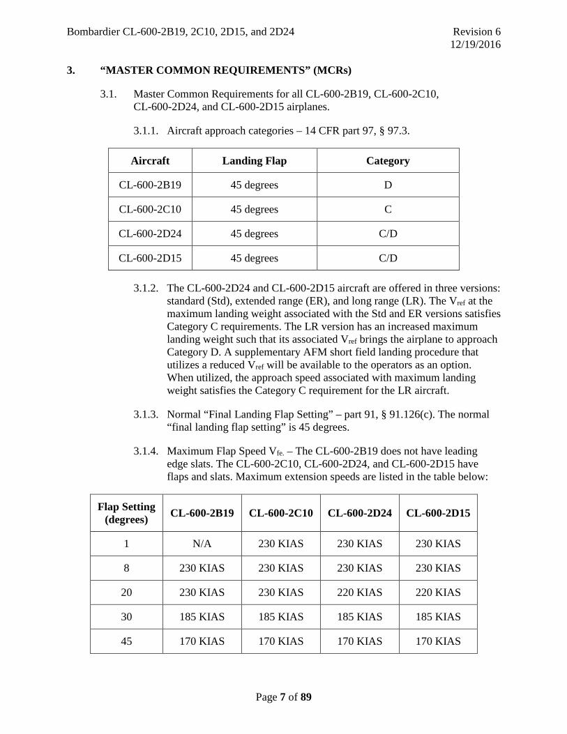
3.1.1. Aircraft approach categories – 14 CFR part 97, § 97.3.
Aircraft Landing Flap Category
CL-600-2B19 45 degrees D
CL-600-2C10 45 degrees C
CL-600-2D24 45 degrees C/D
CL-600-2D15 45 degrees C/D
3.1.2. The CL-600-2D24 and CL-600-2D15 aircraft are offered in three versions: standard (Std), extended range (ER), and long range (LR). The Vref at the maximum landing weight associated with the Std and ER versions satisfies Category C requirements. The LR version has an increased maximum landing weight such that its associated Vref brings the airplane to approach Category D. A supplementary AFM short field landing procedure that utilizes a reduced Vref will be available to the operators as an option. When utilized, the approach speed associated with maximum landing weight satisfies the Category C requirement for the LR aircraft.
3.1.3. Normal “Final Landing Flap Setting” – part 91, § 91.126(c). The normal “final landing flap setting” is 45 degrees.
3.1.4. Maximum Flap Speed Vfe. – The CL-600-2B19 does not have leading edge slats. The CL-600-2C10, CL-600-2D24, and CL-600-2D15 have flaps and slats. Maximum extension speeds are listed in the table below:
Flap Setting (degrees) CL-600-2B19 CL-600-2C10 CL-600-2D24 CL-600-2D15
1 N/A 230 KIAS 230 KIAS 230 KIAS
8 230 KIAS 230 KIAS 230 KIAS 230 KIAS
20 230 KIAS 230 KIAS 220 KIAS 220 KIAS
30 185 KIAS 185 KIAS 185 KIAS 185 KIAS
45 170 KIAS 170 KIAS 170 KIAS 170 KIAS

Bombardier CL-600-2B19, 2C10, 2D15, and 2D24 Revision 6 12/19/2016
Page 8 of 89
3.1.5. Minimum Height for use of the Autopilot – part 121, § 121.579. The minimum height for the use of the autopilot following takeoff is 600 feet AGL.
3.1.6. Procedure Knowledge.
3.1.6.1. Takeoff Profiles. The takeoff profiles are similar for all four models. The only takeoff profile procedural difference between the four models is that the CL-600-2C10, CL-600-2D24, and CL-600-2D15 have one additional callout: “flaps 1” for flap retraction.
4. MASTER DIFFERENCE REQUIREMENTS” (MDRs)
4.1. Master Difference Requirements (MDRs) for the CL-600-2B19, CL-600-2C10, CL-600-2D24, and CL-600-2D15 are shown in Appendix 1. Appendix 1 provisions apply when differences between variations exist which affect crew knowledge, skills, or abilities related to flight safety (e.g., Level A or greater differences).
5. ACCEPTABLE “OPERATOR DIFFERENCE REQUIREMENTS” (ODRs) TABLES
5.1. ODR tables are used to show an operator’s compliance method. Acceptable ODR tables for operators conducting mixed fleet operations, using the particular combination of CL-600-2B19, CL-600-2C10, CL-600-2D24, and CL-600-2D15 variations evaluated, are shown in Appendix 2. The ODR tables represent an acceptable means to comply with MDR provisions, for the airplanes evaluated, based on those differences and compliance methods shown. The tables do not necessarily represent the only acceptable means of compliance for operators with airplanes having other differences, where compliance methods (e.g., flight simulation training devices (FSTD)) are different, or for combinations of airplanes not evaluated. For operators flying variations, which are the same as the airplanes used for the ODR table development, and using the same compliance methods, the ODR tables in Appendix 2 have been found acceptable, and therefore, may be approved by a POI for a particular operator.
5.2. Operator Preparation of ODR Tables. Operators flying “mixed fleet” variations with differences not shown on, or addressed by, the acceptable ODR tables attached in Appendix 2, or operators seeking different means of compliance, must prepare and seek FAA approval from their POI of specific ODR tables pertinent to their fleet. The POI should coordinate this with the FSB Chairman.
5.3. ODR Table Coordination. New ODR tables proposed by operators should be coordinated with the FSB prior to FAA approval and implementation. Through this coordination, the FSB can ensure consistent treatment of variations between

Bombardier CL-600-2B19, 2C10, 2D15, and 2D24 Revision 6 12/19/2016
Page 9 of 89
various operators’ ODR tables and compatibility of the MDR table with MDR provisions.
5.4. ODR Table Distribution. Originally approved ODR tables are retained by the operator. Copies of approved CL-600-2B19, CL-600-2C10, CL-600-2D24, and CL-600-2D15 ODR tables are retained by the Certificate Management Office (CMO). Copies of all approved ODR tables should be forwarded to the FSB Chairman, Long Beach Aircraft Evaluation Group (LGB-AEG).
6. FSB SPECIFICATIONS FOR TRAINING
6.1. General.
6.1.1. The provisions of this section of the report apply to programs for airmen having previous experience in part 121 or 135 air carrier operations and multi-engine transport turbojet or turboprop aircraft. Additional requirements, as determined by the operator’s POI, the FSB, and AFS-200 may be necessary for airmen not having such experience.
6.1.2. CL-600-2B19, CL-600-2C10, CL-600-2D24, and CL-600-2D15 Full Course (Initial) Programs.
Principal Inspectors of operators initially introducing a CL-600-2B19, CL-600-2C10, CL-600-2D24, or CL-600-2D15 aircraft may approve programs consistent with programs previously approved. However, when such programs are approved, operators should be aware that if variations are to be added or differences are to be introduced, ODR table development and FAA approval is necessary prior to operation of those airplanes with differences. For information regarding previously approved programs, FAA Principal Inspectors of other existing CL-600-2B19, CL-600-2C10, CL-600-2D24, and CL-600-2D15 operators may be consulted. In the event of uncertainty regarding evaluation of a proposed program, the FSB Chairman should be consulted.
6.2. Initial, Transition, and Upgrade Training.
6.2.1. Pilots: Initial, Transition, and Upgrade Ground Training – § 121.419.
Initial, transition, or upgrade ground training for the CL-600-2B19, CL-600-2C10, CL-600-2D24 and CL-600-2D15 is accomplished as specified by § 121.419. No unique provisions or requirements are specified. However, if mixed fleet flying with multiple variations, appropriate instruction in systems differences will be required for all variations, consistent with MDR provisions. Training program hours may be reduced as specified in § 121.405, but not in a manner that invalidates compliance with provisions of MDRs.

Bombardier CL-600-2B19, 2C10, 2D15, and 2D24 Revision 6 12/19/2016
Page 10 of 89
6.2.2. Pilots: Initial, Transition, and Upgrade Flight Training – § 121.424.
Initial, transition, or upgrade flight training for the CL-600-2B19, CL-600-2C10, CL-600-2D24, and CL-600-2D15 is accomplished as specified by § 121.424. No unique provisions or requirements are specified. However, if mixed fleet flying with multiple variations, appropriate flight training to suitably address all variations is required, consistent with MDR provisions. Training program hours may be reduced as specified in § 121.405, but not in a manner which invalidates compliance with provisions of MDRs.
6.2.3. Areas of Emphasis. The FSB has identified several airplane systems and/or procedures that should receive special emphasis in an approved CL-600-2B19, CL-600-2C10, CL-600-2D24, and CL-600-2D15 training program.
6.2.3.1. During systems integration training:
a) Flight Control Panel (FCP). b) Flight Mode Annunciator (FMA). c) Flight Management System (FMS). d) Engine (or thrust) Mode Annunciator. e) Full Authority Digital Electronic Control (FADEC)
(if applicable).
6.2.3.2 During flight training (Full Flight Simulator or Airplane):
a) Aileron PCU Runaway. b) Dual Hydraulic System Malfunctions (System 1 or 2 and 3). c) Air Driven Generator (ADG) Deployment. d) Dutch Roll (with yaw dampers operative and inoperative):
1) High Altitude/Slow Speed. 2) 10,000 feet/Landing Configuration.
e) ILS Approach on Standby Instruments. f) Landing with Ground Lift Dumpers (GLD) not deployed. g) Balked landing/low energy go-around. h) Effects of wing leading edge contamination. i) Inadvertent Thrust Reverser Deployment. j) Windshear. k) Hazardous weather and winter operations. l) PFD, MFD, EICAS reversionary modes. m) GPS (If applicable). n) HGS (If applicable). o) EGPWS. p) TCAS.
6.2.4. Training for Seat Dependent Tasks. Accomplishment of certain tasks, procedures, or maneuvers require training of a crewmember for a
Bombardier CL-600-2B19, 2C10, 2D15, and 2D24 Revision 6 12/19/2016
Page 11 of 89
particular crew seat position. Training programs should recognize and address the necessary seat dependent tasks for the applicable crewmembers. See Appendix 8.
6.2.5 Special Event Training. Special event training is recommended for the CL-600-2B19, CL-600-2C10, CL-600-2D24, and CL-600-2D15. Such training should be conducted to improve basic crewmember understanding and confidence regarding airplane handling qualities, options, and procedures as these relate to design characteristics and limitations. Examples of this training could include the following:
a) Recovery from unusual attitudes. b) Handling qualities and procedures during recovery from an upset
condition (e.g., wake vortex encounter). c) Operation of aircraft in icing environments, including super cooled
liquid droplet (SLD) events.
6.2.6 Controlled Flight Into Terrain (CFIT). Due to continued industry efforts to reduce exposure to CFIT accidents, special emphasis on this topic is appropriate. Emphasis on altitude awareness, EGPWS warnings, situational awareness, and crew coordination is appropriate.
6.2.7 Head-up Guidance System (HGS). See Appendix 7.
6.3. Differences Training – § 121.418. Differences training is necessary for qualification in each variation, as shown in the MDR, unless an initial or transition program is completed for each variation. A training program addressing pertinent differences described by individual operator ODRs, including normal, non-normal, and alternate operations, is required for each variation flown. Samples of acceptable ODR tables are shown in Appendix 2.
6.4. Recurrent Training – § 121.427. Recurrent training must include appropriate training in accordance with § 121.427 for each variation. Recurrent training must be in accordance with the initial differences training specified by MDR and ODR tables unless otherwise approved by the POI.
6.4.1. Recurrent Ground Training Time Reductions. If recurrent ground training is reduced below programmed hours required in § 121.427(c), in accordance with § 121.405, such reductions must be consistent with MDR and ODR table provisions.
6.4.2. Recurrent Flight Training. Recurrent flight training requires appropriate maneuvers and procedures identified in part 121 appendix F or as otherwise described in this report. Maneuvers and procedures addressed must account for each variation operated. ODR table provisions identify differences in maneuvers or procedures between variations, which must be addressed in the operator’s recurrent program. As permitted by § 121.441,
Bombardier CL-600-2B19, 2C10, 2D15, and 2D24 Revision 6 12/19/2016
Page 12 of 89
satisfactory completion of a proficiency check, in accordance with part 121 appendix F, may be substituted for training.
6.5. Other Training.
6.5.1. Flight Attendant Initial and Transition Ground Training should be accomplished in accordance with § 121.421. Initial and Transition Ground Training must include a competence check to determine flight attendant ability to perform assigned duties and procedures on the CL-600-2B19, CL-600-2C10, CL-600-2D24, and CL-600-2D15 airplanes. The competence check must address any difference in doors, slides, communications, and each piece of emergency equipment and each emergency procedure unique to each variation.
NOTE: For Model CL-600-2B19, aircraft prior to serial number 7457 have main passenger entry doors that open somewhat slower than main passenger entry doors on aircraft serial number 7457 and subsequent. The aircraft serial number 7457 and subsequent door design is known as a “Phase IV” door, which will touch the ground approximately 10 seconds after being opened. All Models CL-600-2C10, CL-600-2D24, and CL600-2D15 aircraft have “Phase IV” passenger doors.
6.5.2. Aircraft Dispatcher Initial and Transition Ground Training should be accomplished for each variation in accordance with § 121.422. Where variations have different performance, procedures, or limitations (i.e., flex thrust, CAT III), dispatchers must be trained to suitably address those differences.
6.5.3. Operating Experience (OE) should be accomplished in accordance with § 121.434.
6.5.4. Line Oriented Flight Training (LOFT) – § 121.409(b)(2)(ii). When operators have LOFT programs, and variations are approved, POIs must review LOFT programs to ensure applicability for each variation.
7. FSB SPECIFICATIONS FOR CHECKING
7.1. General.
7.1.1. Checking Items. Knowledge, procedures, and maneuvers specified by part 61, part 121 appendix F, FAA Order 8900.1, or FAA Practical Test Standards (PTS) pertinent to multi-engine turbojet transport aircraft apply. part 121 checking items are accomplished as specified by MDRs and ODRs to qualify in pertinent variations.

Bombardier CL-600-2B19, 2C10, 2D15, and 2D24 Revision 6 12/19/2016
Page 13 of 89
7.1.2. Areas of Emphasis. The following areas of emphasis should be demonstrated during checking:
7.1.2.1. Proficiency in manual and automatic flight in normal, abnormal, and emergency situations must be demonstrated at each proficiency check by all crewmembers, and
7.1.2.2. The use of manual system modes (electrical, fuel, hydraulics, pressurization, etc.) and backup equipment (i.e., ADG) must be demonstrated at each proficiency check by all crewmembers.
7.1.3. No Flap Approaches and Landings. Demonstration of a no flap approach and landing during a part 61 or part 121 appendix F check is required per the Airline Transport Pilot and/or Type Rating Practical Test Standards - FAA-S-8081-5F Area of Operation VI, Task I. The “Flap 1” (slats 20/Flaps 0) position should be used for this demonstration in the CL 600-2C10, CL-600-2D24, and CL-600-2D15. In accordance with Order 8900.1, when the flight demonstration is conducted in an airplane, versus a full flight simulator (FFS), touchdown from a no flap approach is not required. The approach must be flown to the point where the inspector or examiner can determine whether the landing would or would not occur in the touchdown zone.
7.2 Type Ratings/
7.2.1 Oral and Written Tests. Unless otherwise specified by ODR tables, an oral or written portion of a type rating practical test need only address the variation to be flown or to be used to conduct the test, as determined by the inspector/examiner conducting the test.
7.2.2 Airmen may complete the necessary type rating practical test of part 61, part 121 appendix F, Order 8900.1, FAA Practical Test Standards in any variation for issuance of a “CL-65” pilot type rating. However, before airmen serve as PIC under part 121 or 125 in a variation other than that in which a type rating practical test was completed, checking for differences in accordance with MDR provisions must be completed.
7.2.3 Additional Factors for Practical Tests for Applicants Not Employed under part 121.
7.2.4 A practical test for an applicant not employed under part 121 (e.g., issuance of a type rating under part 61 or 142) must be conducted in a variation that the applicant was trained under.
7.3 Proficiency Checks.
7.3.1 General. Proficiency checks are administered as designated in § 61.58 or § 121.441 and part 121 appendix F. Each check should assess knowledge

Bombardier CL-600-2B19, 2C10, 2D15, and 2D24 Revision 6 12/19/2016
Page 14 of 89
and acceptable levels of skill, considering the variations flown and crew position. Satisfactory completion of a proficiency check may be substituted for recurrent flight training as permitted in § 121.433(c).
7.3.2 Alternating Proficiency Checks for CL-600-2B19, CL-600-2C10, CL-600-2D24, and CL-600-2D15.
For mixed-fleet-flying proficiency, checks should alternate between variations each 6 months for PICs and annually for other flightcrew members. The CL-600-2C10, CL-600-2D24, and CL-600-2D15 may be considered as one variation for alternating proficiency checks with the CL-600-2B19. In other words, a pilot may take a proficiency check in the CL-600-2B19, then, 6 months later, take a proficiency check in either the CL-600-2C10, CL-600-2D24, or CL-600-2D15, or vice versa. When such alternating airplane checks are accomplished, the differences may be satisfied by ground training, written questionnaire, oral review, or other method approved by the POI. However, such simplified programs may not be approved if they result in progressive loss of knowledge or skills related to particular differences over successive recurrent periods.
7.3.3 Section 61.58 Proficiency checks which do not pertain to part 121.
Proficiency checks which may be required in accordance with § 61.58, but which do not pertain to part 121 operations, must be administered using the same variation as the airplane intended to be flown (e.g., an airman intending to fly a CL-600-2B19 should take a proficiency check in a CL-600-2B19 FFS).
7.3.4 Line Checks – § 121.440.
Line checks completed in the CL-600-2B19, CL-600-2C10, CL-600-2D24, or CL-600-2D15 will satisfy requirements for all four airplanes.
7.3.5 Head-up Guidance System (HGS).
When HGS use is approved, checking must include suitable demonstration of HGS use for modes and phases of flight authorized. Checking standards for HGS are equivalent to those for non-HGS operations. Periodic assessment of non-HGS skills should also be demonstrated; therefore, each check pilot/inspector may request that authorized maneuvers be performed without use of HGS (e.g., if manual CAT II F/D operations are authorized, the airman being checked may be requested to perform the maneuver without HGS). See appendix 7.

Bombardier CL-600-2B19, 2C10, 2D15, and 2D24 Revision 6 12/19/2016
Page 15 of 89
8. FSB SPECIFICATIONS FOR CURRENCY
8.1. Currency (Recency of Experience) is in accordance with § 121.439. Currency is considered to be common for the CL-600-2B19, CL-600-2C10, CL-600-2D24, and CL-600-2D15. Separate tracking of currency for the CL-600-2B19, CL-600-2C10, CL-600-2D24, and CL-600-2D15 is not necessary or applicable.
9. AIRCRAFT REGULATORY COMPLIANCE CHECKLIST
9.1. Compliance Checklists (Appendices 3, 4, 5, and 6). Compliance checklists are provided as an aid to FAA Certificate Management Offices (CMOs) to identify those specific rules or policies for which compliance has already been demonstrated to the FAA for a particular type or variation. The checklist also notes rules or policies that remain to be demonstrated to CMOs by operators. Not all rules or policies or variations are necessarily listed or addressed. When differences exist between the variations evaluated with the compliance checklist and variations used by an operator, the CMO must evaluate those differences and approve use of the variations, if that variation provides compliance with 14 CFRs and FAA policies. It remains the responsibility of the operator to show compliance to their FSDO or CMO, and for the FSDO or CMO to review compliance with pertinent rules and policies not addressed in the compliance checklists shown in Appendix 3, 4, 5, or 6, prior to part 121 or 125 approval of an operator for use of the CL-600-2B19, CL-600-2C10, CL-600-2D24, or CL-600-2D15. Part 135 was not evaluated by the FSB, as it was determined to not be applicable.
9.2 Discussion of Specific Compliance Checklist Items.
9.2.1 Emergency Evacuation. All the listed emergency evacuation findings accomplished under simulated demonstration were completed in accordance with § 125.803 and are credited under § 121.291 for configurations and passenger capacities specified below.
a) CL-600-2B19 – This model aircraft has demonstrated, under simulated full-scale emergency evacuation tests, successful evacuation of 50 passengers and three crewmembers (two pilots and one flight attendant). Accordingly, an additional § 121.291 full-scale evacuation is not necessary for airplane configurations consistent with previously approved tests. Passenger capacity less than or equal to the previously demonstrated capacity may be authorized. A partial evacuation is required unless the particular certificate holder has previously operated a CL-600-2B19 with the same or similar interior and exit configuration.
b) CL-600-2C10 – This model aircraft has demonstrated, under simulated full-scale emergency evacuation tests, successful evacuation of 78 passengers and four crewmembers (two pilots and two flight

Bombardier CL-600-2B19, 2C10, 2D15, and 2D24 Revision 6 12/19/2016
Page 16 of 89
attendants). Accordingly, an additional § 121.291 full-scale evacuation is not necessary for airplane configurations consistent with previously approved tests. Passenger capacity less than or equal to the previously demonstrated capacity may be authorized. A partial evacuation is required unless the particular certificate holder has previously operated a CL-600-2C10 with the same or similar interior and exit configuration.
c) CL-600-2D24 – This model aircraft has demonstrated, under simulated full-scale emergency evacuation tests, successful evacuation of 90 passengers and four crewmembers (two pilots and two flight attendants). Accordingly, an additional § 121.291 full-scale evacuation is not necessary for airplane configurations consistent with previously approved tests. Passenger capacity less than or equal to the previously demonstrated capacity may be authorized. A partial evacuation is required unless the particular certificate holder has previously operated a CL-600-2D24 with the same or similar interior and exit configuration.
d) CL-600-2D15 – This model aircraft is identical to the CL-600-2D24 with the exception that it is certified for 75 passengers only. A partial evacuation is required unless the particular certificate holder has previously operated a CL-600-2D24 with the same or similar interior and exit configuration.
9.2.2 Proving Tests – § 121.163(c). The CL-600-2C10, CL-600-2D24, and CL-600-2D15 are considered variations of the CL-600-2B19 and have not been significantly altered except for fuselage plugs, leading edge slats, and FADEC engines. Proving tests in accordance with § 121.163(b) are appropriate in accordance with Order 8900.1, Volume 3, Chapter 29 when the CL-600-2B19, CL-600-2C10, CL-600-2D24, or CL-600-2D15 is new to a particular operator. When an operator is currently operating the CL-600-2B19, CL-600-2C10, CL-600-2D24, or CL-600-2D15, and the operator introduces a variation into the same operations, proving tests are not required. Proving test requirements and reductions are as designated by Order 8900.1 and the CMO, or as otherwise specified by the FSB or AFS-200.
10. FSB SPECIFICATIONS FOR FLIGHT SIMULATION TRAINING DEVICES (FSTDs)
10.1. FSTD characteristics pertinent to the CL-600-2B19, CL-600-2C10, CL-600-2D24, and CL-600-2D15 are as specified by 14 CFR part 60, § 121.407, part 121 appendix H, and AC 120-53, except as described below. Tutorial Computer-Based Instruction (TCBI) and Interactive Computer-Based Instruction (ICBI) are referenced in Appendix 2.
Bombardier CL-600-2B19, 2C10, 2D15, and 2D24 Revision 6 12/19/2016
Page 17 of 89
10.2. Use of Flight Training Devices (FTDs) for Specific Check/Evaluation Items. Certain ATP, type rating, or proficiency check/evaluation items may be completed in FAA qualified FTDs. This is appropriate for items such as FMS initialization or engine start non-normals. Specific checking credit in such instances must be approved by the POI.
10.3. FSTD Compatibility – § 121.407. When variations are flown in mixed fleets, the combination of FSTDs used to satisfy MDR or ODR provisions must match specific variations flown by that operator. The acceptability of differences between FTDs, FFS, and aircraft operated must be addressed by the POI.
10.4. Flight Training Device Approval. Requests for device approval should be made to the POI. If device characteristics clearly meet established FAA criteria and are qualified, the POI may approve those devices for that carrier. Where devices do not clearly satisfy a given level, POIs should request advice from the FSB Chairman (AEG), National Simulator Program (NSP), or AFS-200.
10.5. Door Trainers. Training in accordance with § 121.417 must be conducted on an airplane or in a training device representative of the operator’s fleet configuration.
11. APPLICATION OF FSB REPORT
11.1 All relevant parts of this report are applicable to operators on the approval date of this report.
12. MISCELLANEOUS
12.1 Extended Range Operation with Two Engine Airplanes (ETOPS). The CL-600-2B19, Cl-600-2C10, CL-600-2D24, and CL-600-2D15 have not been evaluated for ETOPS in accordance with AC 120-42A.
Bombardier CL-600-2B19, 2C10, 2D15, and 2D24 Revision 6 12/19/2016
Page 18 of 89
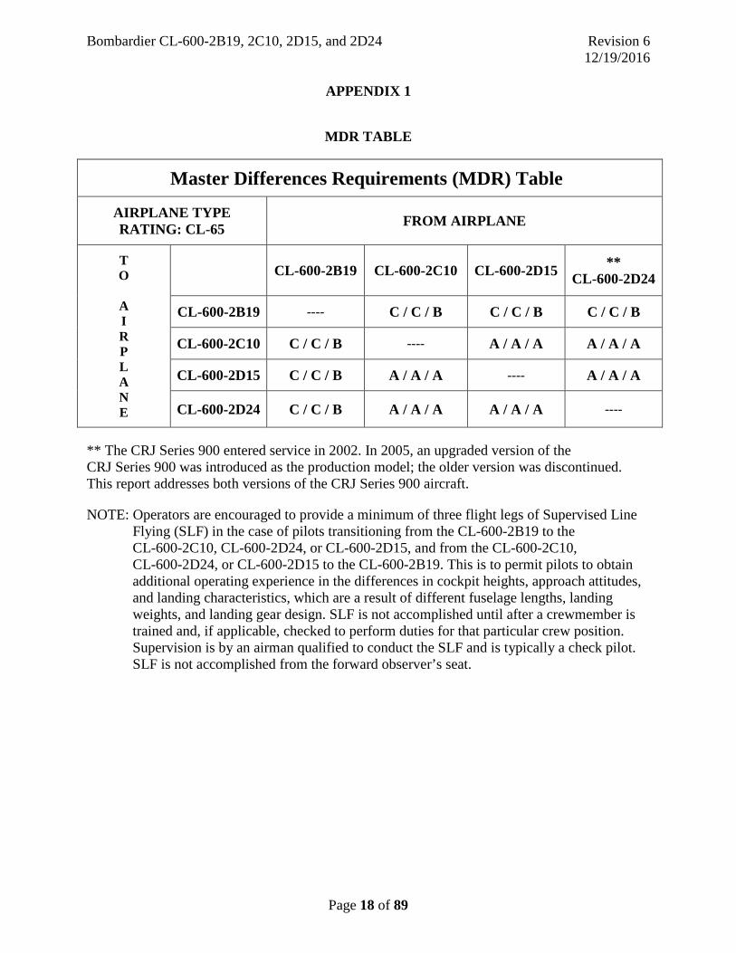
APPENDIX 1
MDR TABLE
Master Differences Requirements (MDR) Table
AIRPLANE TYPE RATING: CL-65 FROM AIRPLANE
T O
A I R P L A N E
CL-600-2B19 CL-600-2C10 CL-600-2D15 ** CL-600-2D24
CL-600-2B19 ---- C / C / B C / C / B C / C / B
CL-600-2C10 C / C / B ---- A / A / A A / A / A
CL-600-2D15 C / C / B A / A / A ---- A / A / A
CL-600-2D24 C / C / B A / A / A A / A / A ----
** The CRJ Series 900 entered service in 2002. In 2005, an upgraded version of the CRJ Series 900 was introduced as the production model; the older version was discontinued. This report addresses both versions of the CRJ Series 900 aircraft.
NOTE: Operators are encouraged to provide a minimum of three flight legs of Supervised Line Flying (SLF) in the case of pilots transitioning from the CL-600-2B19 to the CL-600-2C10, CL-600-2D24, or CL-600-2D15, and from the CL-600-2C10, CL-600-2D24, or CL-600-2D15 to the CL-600-2B19. This is to permit pilots to obtain additional operating experience in the differences in cockpit heights, approach attitudes, and landing characteristics, which are a result of different fuselage lengths, landing weights, and landing gear design. SLF is not accomplished until after a crewmember is trained and, if applicable, checked to perform duties for that particular crew position. Supervision is by an airman qualified to conduct the SLF and is typically a check pilot. SLF is not accomplished from the forward observer’s seat.
Bombardier CL-600-2B19, 2C10, 2D15, and 2D24 Revision 6 12/19/2016
Page 19 of 89
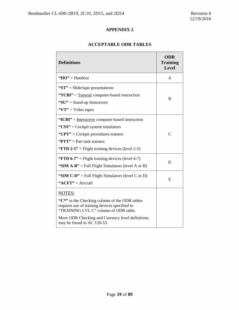
APPENDIX 2
ACCEPTABLE ODR TABLES
Definitions ODR
Training Level
“HO” = Handout A
“ST” = Slide/tape presentations
“TCBI” = Tutorial computer-based instruction
“SU” = Stand-up Instructors
“VT” = Video tapes
B
“ICBI” = Interactive computer-based instruction
“CSS” = Cockpit system simulators
“CPT” = Cockpit procedures trainers
“PTT” = Part task trainers
“FTD 2-5” = Flight training devices (level 2-5)
C
“FTD 6-7” = Flight training devices (level 6-7)
“SIM A-B” = Full Flight Simulators (level A or B) D
“SIM C-D” = Full Flight Simulators (level C or D)
“ACFT” = Aircraft E
NOTES: “C*” in the Checking column of the ODR tables requires use of training devices specified in “TRAINING LVL C” column of ODR table.
More ODR Checking and Currency level definitions may be found in AC 120-53.

Bombardier CL-600-2B19, 2C10, 2D15, and 2D24 Revision 6 12/19/2016
Page 20 of 89
APPENDIX 2
ACCEPTABLE ODR TABLES
DIFFERENCE AIRCRAFT: CL-600-2C10 BASE AIRCRAFT: CL-600-2B19 APPROVED BY (POI)____________________________
COMPLIANCE METHOD
TRAINING CHKG/CURR
DESIGN REMARKS FLT CHAR
PROC CHNG
LVL A
LVL B
LVL C
LVL D CHK CURR
Aircraft General Fuselage Length: 106 ft, 8 in. (32.51 m) Increase of 18 ft, 10 in. (5.74 m) Wingspan: 76 ft, 3 in. (23.25 m) Increase of 6 ft, 9 in. (2.04 m) Tail span: 28 ft (8.54 m) Increase of 7 ft, 8 in. (2.34 m) Height: 24 ft, 10 in. (7.57 m) Increase of 4 ft, 2 in. (1.27 m)
No No HO A A
Aircraft General Performance Max T.O. Weight: 75,000 lb. (34,020 kg) Increase of 22,000 lb. (9,979 kg) Max Landing Weight: 67,000 lb. (30,390 kg) Increase of 20,000 lb. (9,072 kg) Fuel Capacity: 2902 U.S. gal. (10,977 L) Increase of 751 gal (2,835 L)
No No HO A B
Aircraft General Wheel Base Main Wheel Track: 13 ft, 6 in. (4.0 m) Increase of 3 ft, 2 in. (0.96 m) Nose to Main Wheels: 40 ft, 10 in. (12.44 m) Increase of 4 ft, 6 in. (1.37 m)
No No HO A A
Aircraft General Powerplant GE CF34-8C1 or GE CF34-8C5B1 13,790 lb. of thrust, APR Increase of 4,570 lb. of thrust
No No HO A A
Aircraft General Forward cargo bay No Yes Emerg. HO A A

Bombardier CL-600-2B19, 2C10, 2D15, and 2D24 Revision 6 12/19/2016
Page 21 of 89
DIFFERENCE AIRCRAFT: CL-600-2C10 BASE AIRCRAFT: CL-600-2B19 APPROVED BY (POI)____________________________
COMPLIANCE METHOD
TRAINING CHKG/CURR
DESIGN REMARKS FLT CHAR
PROC CHNG
LVL A
LVL B
LVL C
LVL D CHK CURR
Aircraft General Increase of 20 passengers in payload capacity No No HO A A
Aircraft General Addition of second Flight Attendant position No No HO A A
24 Electrics Revised architecture No Yes
Normals ST,
TCBI, SU, VT
A B
27 Flight Controls Three panel slats on each wing Minor Yes
Normals ST,
TCBI, SU, VT
A A
49 APU Tail cone mounted No Minor
Normals HO A A
52 Doors Forward cargo bay door No Minor
Normals HO A A
Limitations APU operating limits; Engine parameters; Gear extension speed. These are not all inclusive.
No Yes Limits
ST, TCBI,
SU, VT B B

Bombardier CL-600-2B19, 2C10, 2D15, and 2D24 Revision 6 12/19/2016
Page 22 of 89
DIFFERENCE AIRCRAFT: CL-600-2C10 BASE AIRCRAFT: CL-600-2B19 APPROVED BY (POI)____________________________
COMPLIANCE METHOD
TRAINING CHKG/CURR
SYSTEM REMARKS FLT CHAR
PROC CHNG
LVL A
LVL B
LVL C
LVL D CHK CURR
21 ECS Recirculated air distribution system with fan control switch No Minor
Normals HO A A
21 ECS No dedicated fan for avionics bay cooling No Minor
Normals HO A A
21 ECS No dedicated standby fan for EFIS cooling. Backup cooling is via ECS airflow. No Minor
Normals HO A A
21 ECS Selected and actual temp displayed on ECS synoptic page No Minor
Normals HO A A
21 ECS Revised architecture. No dedicated cargo bay fan No No HO A A
21 ECS Revised architecture. One electrically operated outflow valve, two safety valves, one ground valve
No No HO A A
24 Electrics CB panels 3 and 4 removed; 40 KVA generator (no load shedding for failed generator); Generator switches (3) always left in AUTO; AC utility buses removed; ACPC controls switching automatically; 4 - 120A TRUs instead of 5 - 100A TRUs; Bus Ties are automatic (controlled by DCPC). Switchlights removed on electrical power panel; Service bus powered from DC bus 2; One DC utility bus; DC external power plug and DC External switchlight removed; New ADG bus installed. AC electric synoptic changes ADC (no lamp test) Battery chargers and battery location
No Minor Normals
ST, TCBI,
SU, VT B B
26 Fire/Ovht Simplified testing procedure. Automatic BITE and MDC interface No Minor
Normals HO A A
26 Fire/Ovht No jetpipe overheat detection No No HO A A 26 Fire/Ovht Fire suppression for forward cargo area.
Common Halon system used to supply both compartments. Three cargo smoke detectors.
No Minor Normals HO A A
27 Flight Controls
No dedicated spoiler on control surface. Multifunction spoilers act as flight spoiler or spoiler on or ground lift dump.
No No ST,
TCBI, SU, VT
A A
27 Flight Controls
No flutter dampers on elevators No No HO A A
27 Flight Controls
Rudder limiter incorporated, function of speed and flap position controlled by SSCU No No
ST, TCBI,
SU, VT A A

Bombardier CL-600-2B19, 2C10, 2D15, and 2D24 Revision 6 12/19/2016
Page 23 of 89
DIFFERENCE AIRCRAFT: CL-600-2C10 BASE AIRCRAFT: CL-600-2B19 APPROVED BY (POI)____________________________
COMPLIANCE METHOD
TRAINING CHKG/CURR
SYSTEM REMARKS FLT CHAR
PROC CHNG
LVL A
LVL B
LVL C
LVL D CHK CURR
27 Flight Controls
The power up BITE test starts only when all three hydraulic systems are fully powered. A SPLR/STAB IN TEST advisory message is posted on EICAS during this test - All flight control systems are inoperative during the test
No Minor Normals HO A A
27 Flight Controls
For redundancy, emergency slat/flap switch added to drive slats to 25 degrees and flaps to 20 degrees with a slat/flap selector failure
No Yes
Abnormal
ST,
TCBI, SU, VT
B B
27 Flight Controls
Slat/Flap lever has 6 positions No Minor
Normals HO A A
28 Fuel No gravity refuel capability on center tank No Yes HO A A 28 Fuel Dedicated cross-flow pump No No HO A A 28 Fuel Bulk fuel temperature sensor in right main
tank No No HO A A
28 Fuel Fuel synoptic changes No No HO A A
29 Hydraulics 1B/2B pump is not load shed when respective engine GEN is not operating No
Minor Abnorma
l HO A A
29 Hydraulics Thrust reversers are powered by hydraulics No No HO A A 29 Hydraulics Hydraulic SOV switches added to isolate
EDP during low pressure condition without shutting down the engine No
Minor Normals Abnorma
l
ST,
TCBI, SU, VT
B B
30 Ice and Rain
No cowl anti-ice blow out plug on engines No Minor
Normals HO A A
30 Ice and Rain
Revised architecture for cowl anti-icing duct leak detection in pylon area No
Minor New msg.
HO A A
30 Ice and Rain
Simplified cowl and wing anti-ice synoptic page No No HO A A
30 Ice and Rain
Air data probes and sensor anti-icing tested before flight with ICE DET switchlight No Minor
Normals HO A A
30 Ice and Rain
Revised architecture for wing OVHT protection. No STBY mode for wing anti-ice required.
No No HO A A
30 Ice and Rain
Windshield wiper has intermittent position. NO No HO A A
30 Ice and Rain
Variable white arcs on the N2 gauges. Range of arc varies with engine bleed condition.
No No ST,
TCBI, SU, VT
B B
30 Ice and Rain
Wing anti-ice system tested continuously. No test switch (automatic function) No Minor
Normals HO A A

Bombardier CL-600-2B19, 2C10, 2D15, and 2D24 Revision 6 12/19/2016
Page 24 of 89
DIFFERENCE AIRCRAFT: CL-600-2C10 BASE AIRCRAFT: CL-600-2B19 APPROVED BY (POI)____________________________
COMPLIANCE METHOD
TRAINING CHKG/CURR
SYSTEM REMARKS FLT CHAR
PROC CHNG
LVL A
LVL B
LVL C
LVL D CHK CURR
32 Landing gear
Nose doors are mechanical No No HO A A
32 Landing gear
Cantilever assemblies on main gear with shimmy dampers No Minor
Normals HO A A
32 Landing gear
No main gear dust pin covers No No HO A A
32 Landing gear
No FLT/NORM switch installed on forward external service panel No Minor
Normals HO A A
32 Landing gear
No anti-skid test switch. Revised anti-skid test procedure. No Yes
Normals ST,
TCBI, SU, VT
B B
32 Landing gear
NWS deflection is +/- 80 degrees with tiller and rudder pedal movement will deflect NW +/- 8 degrees
No No HO A A
33 Lighting Overhead panel dome lights installed No No HO A A 33 Lighting Single nose landing light No No HO A A 33 Lighting Three exterior lights per side for emergency
exit lighting No No HO A A
33 Lighting No EMER LTS OFF light on panel. EMER LTS OFF caution message only No
Minor Normals Abnorma
l
HO A A
34 Flight Instr.
No mach transducer or selector valves in Pitot Static system No Minor
Normals HO A A
34 Flight Instr.
One electronic integrated standby instrument provides airspeed, altitude, attitude, slip/skid, and localizer/glideslope information
No Minor Normals HO A A
35 Oxygen Overboard discharge indicator located on left side of fuselage No No HO A A
36 Pneumatics New flight deck bleed air panel. Engine bleed air taken from either 6th or 10th stage to supply common manifold. Bleed air selection is automatic when in AUTO mode. Provisions for manual switching.
No
Yes Normals/ Abnorma
l
ST,
TCBI, SU, VT
B B
36 Pneumatics Power On automatic bleed air leak detection test No Minor
Normals HO A A
49 APU 40 KVA generator No APU Intake Door 'MID' EICAS indication Dedicated APU fuel pump APU Fuel supply, left collector tank AVAIL light = ready for electrical loading, ECU determines when pneumatic loading is available. No fire horn. Start cycle.
No No ST,
TCBI, SU, VT
A B

Bombardier CL-600-2B19, 2C10, 2D15, and 2D24 Revision 6 12/19/2016
Page 25 of 89
DIFFERENCE AIRCRAFT: CL-600-2C10 BASE AIRCRAFT: CL-600-2B19 APPROVED BY (POI)____________________________
COMPLIANCE METHOD
TRAINING CHKG/CURR
SYSTEM REMARKS FLT CHAR
PROC CHNG
LVL A
LVL B
LVL C
LVL D CHK CURR
70 Powerplant FADEC controlled
No Minor Normals
ICBI, CSS, CPT, FTD 2-5
B B
70 Powerplant N1 and N2 sync control panel
No
Minor Normals Abnorma
l
HO A A
70 Powerplant FADEC controlled start cycle for ATS and windmill starts
No Minor Normals
ICBI, CSS, CPT, FTD 2-5
B B
70 Powerplant Thrust reversers hydraulically-actuated. No thrust lever retarder control system No No
ST, TCBI,
SU, VT B B
70 Powerplant No emergency stow PBAs No Minor
Normals ST,
TCBI, SU, VT
B B
70 Powerplant High power schedule PBA No Yes
ST, TCBI,
SU, VT B B
70 Powerplant FADEC generated thrust limits for: (automatic with thrust levers in respective detent) Takeoff (TO) Flex (FLX) Climb (CLB) GoAround (GA) Max Continuous Thrust (MCT) Cruise (CRZ) - manually set in the cruise range
No No ST,
TCBI, SU, VT
B B
70 Powerplant Engine oil test panel removed. Engine oil level quantities provided on menu page No Minor
Normals HO A A

Bombardier CL-600-2B19, 2C10, 2D15, and 2D24 Revision 6 12/19/2016
Page 26 of 89
DIFFERENCE AIRCRAFT: CL-600-2C10 BASE AIRCRAFT: CL-600-2B19 APPROVED BY (POI)____________________________
COMPLIANCE METHOD
TRAINING CHKG/CURR
MANEUVER REMARKS FLT CHAR
PROC CHNG
LVL A
LVL B
LVL C
LVL D CHK CURR
AFCS Initial take off pitch target is optimized to takeoff V speeds entered No No ST, TCBI,
SU, VT B B
Takeoff Rotation rate is 3-5 degrees per second towards target FD No No ST, TCBI,
SU, VT A A
Takeoff Throttles placed in "TOGA" detent and thrust is set into N1 caret by FADEC Throttles placed in "CLB" detent and thrust is set into N1 caret by FADEC
No No CSS, PTT,
FTD2-5 B B
Takeoff Flap retraction: Flaps 8 takeoff - Flaps retracted to '1' from '8' at V2 + 12 and to '0' from '1' at VT -15 kts Flaps 20 takeoff - Flaps retracted to '8' from '20' at V2 + 12 and to '1' from '8' at V2 + 20 and then to '0' from '1' at VT -15
No Yes Normals
CSS, PTT,
FTD2-5 C* B
Approach Approach Attitude Comparison CRJ200……………...CRJ700 Single Engine……….Normal N/A………………….Flapless (Slats 25) Normal………………Slatless (Flaps 45) Flapless……………..Single Engine
Yes No VT B A
Landing
More pronounced flare Yes No VT B B

Bombardier CL-600-2B19, 2C10, 2D15, and 2D24 Revision 6 12/19/2016
Page 27 of 89
DIFFERENCE AIRCRAFT: CL-600-2B19 BASE AIRCRAFT: CL-600-2C10 APPROVED BY (POI)____________________________
COMPLIANCE METHOD
TRAINING CHKG/CURR
DESIGN REMARKS FLT CHAR
PROC CHNG
LVL A
LVL B
LVL C
LVL D CHK CURR
Aircraft General
Fuselage Length: 87 ft, 10 in. (26.77 m) Decrease of 18 ft, 10 in. (5.74 m) Wingspan: 69 ft, 6 in. (21.21 m) Decrease of 6 ft, 9 in. (2.04 m) Tailspan: 20 ft, 4 in. (6.2 m) Decrease of 7 ft, 8 in. (2.34 m) Height: 20 ft, 8 in. (6.3 m) Decrease of 4 ft, 2 in. (1.27 m)
No No HO A A
Aircraft General
Performance Max T.O. Weight: 53,000 lb. (24,041 kg) Decrease of 22,000 lb. (9,979 kg) Max Landing Weight: 47,000 lb. (21,319 kg) Decrease of 20,000 lb. (9,072 kg) Fuel Capacity: 2151 U.S. gal. (8,142 L) Decrease of 751 gal. (2,835 L)
No No HO A A
Aircraft General
Wheel Base Main Wheel Track: 10 ft, 4 in. (3.1 m) Decrease of 3 ft, 2 in. (0.96 m) Nose to Main Wheels: 36 ft, 4 in. (11.07 m) Decrease of 4 ft, 6 in. (1.37 m)
No No HO A A
Aircraft General
Powerplant GE CF34-3B1 9,220 lb. of thrust, APR Decrease of 4,570 lb. of thrust
No No HO A A
Aircraft General
No forward cargo bay No Minor HO A A
Aircraft General
Decrease of 20 passengers in payload capacity No No HO A A
Aircraft General
One Flight Attendant position No No HO A A

Bombardier CL-600-2B19, 2C10, 2D15, and 2D24 Revision 6 12/19/2016
Page 28 of 89
DIFFERENCE AIRCRAFT: CL-600-2B19 BASE AIRCRAFT: CL-600-2C10 APPROVED BY (POI)____________________________
COMPLIANCE METHOD
TRAINING CHKG/CURR
DESIGN REMARKS FLT CHAR
PROC CHNG
LVL A
LVL B
LVL C
LVL D CHK CURR
24 Electrics Architectural differences No Minor
(Ext. DC) ST,
TCBI, SU, VT
A A
27 Flight Controls
No slats on wings Minor Yes
Normals HO A A
49 APU Located in aft equipment bay Intake/exhaust/Hazard areas No Minor
Normals HO A A
52 Doors No forward cargo bay door No Minor
Normals HO A A
Limitations APU operating limits; Engine parameters, Gear extension speed, windshield wipers, single pack ops., crosswind, cargo (fire), cold soak (T/R’s). These are not all inclusive.
No Yes Limits
ST, TCBI,
SU, VT B B

Bombardier CL-600-2B19, 2C10, 2D15, and 2D24 Revision 6 12/19/2016
Page 29 of 89
DIFFERENCE AIRCRAFT: CL-600-2B19 BASE AIRCRAFT: CL-600-2C10 APPROVED BY (POI)____________________________
COMPLIANCE METHOD
TRAINING CHKG/CURR
SYSTEM REMARKS FLT CHAR
PROC CHNG
LVL A
LVL B
LVL C
LVL D CHK CURR
21 ECS No recirculation feature No Minor
Normals HO A A
21 ECS Dedicated avionics bay cooling system with fan control No Minor
Normals ST, TCBI, SU, VT B A
21 ECS Cabin actual temperature indications only No Minor
Normals HO A A
21 ECS Dedicated cargo bay fan No Minor
Msg. HO A A
21 ECS Architectural differences: two pneumatically controlled outflow/safety valves, overboard and inboard ground valves
No No HO A A
24 Electrics CB panels 3 and 4 in Flight Deck; 30 KVA generator (load shedding for failed generator); Generator switches (3) manually selected from OFF to ON after engine start; Two AC utility busses, load shed under certain conditions; No ACPC installed, individual relays accomplish switching; 5 - 100A TRUs instead of 4 - 120A TRUs; Bus Ties 1 and 2 are automatic. ESS Tie is manually selected. Switchlights on electrical power service panel; Service bus powered from SERV TRU; Two DC utility busses; DC external power plug with External DC Switchlight on electrical panel; ADG feeds directly to AC Essential Bus. System affected during AC power transfer (loss of AC Bus 2). Battery charger; battery location.
No
Minor Normals, Abnorma
l, Emergen
cy
ST, TCBI, SU, VT B B
26 Fire/Ovht Non-automated testing procedure. No Yes
Normals ICBI, CSS, CPT, PTT, FTD 2-5
C B
26 Fire/Ovht JETPIPE OVHT detection Emergency Procedure (Recall) No Msg. ST, TCBI,
SU, VT B B
27 Flight Controls
Dedicated spoileron control surface and dedicated flight spoiler control surface No No HO A A
27 Flight Controls
Flutter dampers on elevators No No HO A A
27 Flight Controls
No rudder limiter No No HO A A
27 Flight Controls
No power up Bite test or SPLR/STAB IN TEST advisory message No Minor
Normals HO A A
27 Flight Controls
No emergency flap switch No
Yes Abnorma
l HO A A

Bombardier CL-600-2B19, 2C10, 2D15, and 2D24 Revision 6 12/19/2016
Page 30 of 89
DIFFERENCE AIRCRAFT: CL-600-2B19 BASE AIRCRAFT: CL-600-2C10 APPROVED BY (POI)____________________________
COMPLIANCE METHOD
TRAINING CHKG/CURR
SYSTEM REMARKS FLT CHAR
PROC CHNG
LVL A
LVL B
LVL C
LVL D CHK CURR
27 Flight Controls
Flap lever has 5 positions No Minor
Normals HO A A
28 Fuel Gravity refuel capability on center tank No Yes HO A A 28 Fuel Shared APU and crossflow fuel pump No No HO A A 28 Fuel Bulk fuel temperature sensor in left main tank
No No HO A A
29 Hydraulics 1B/2B pump is load shed when opposite GEN is not operating No
Minor Abnorma
l HO A A
29 Hydraulics No hydraulic SOV switches No
Minor Abnorma
l HO A A
30 Ice and Rain Cowl anti-icing valves pressure regulated with overpressure protection (Anti-ice blow out plug on engines)
No Minor Normals HO A A
30 Ice and Rain Revised architecture for cowl anti-icing duct leak detection in pylon area No Minor HO A A
30 Ice and Rain Air data probes and sensor anti-icing not tested No No HO A A
30 Ice and Rain Wing anti-icing two operating temperature modes NORM and STBY are manually selectable
No Minor
Abnormal
ST, TCBI, SU, VT B A
30 Ice and Rain Amber arcs on the N2 gauges. Range from 0 -78% No No HO A A
30 Ice and Rain Wing anti-ice system test switch No Minor
Normals ST, TCBI, SU, VT B B
30 Ice and Rain Architectural differences on synoptic page No No HO A A 30 Ice and Rain Cowl and wing anti-ice deactivated during
thrust reverser deployment No No HO A A
32 Landing gear Nose doors are powered by hydraulics No Minor
Normals FTD 2-5 B A
32 Landing gear Trailing link assemblies on main gear shimmy dampers
without No No HO A A
32 Landing gear Main gear pin dust cover No Minor
Normals HO A A
32 Landing gear FLT/NORM switch on forward external service panel No Minor
Normals ST, TCBI, SU, VT B A
32 Landing gear Anti-skid test switch Parking brake OFF. No Yes
Normals ST, TCBI, SU, VT B A
32 Landing gear NWS deflection is +/- 70 degrees with tiller and rudder pedal movement will deflect NW +/- 5 degrees
No No HO A A
33 Lighting No overhead panel dome lights No No HO A A 33 Lighting Dual nose landing lights No No HO A A

Bombardier CL-600-2B19, 2C10, 2D15, and 2D24 Revision 6 12/19/2016
Page 31 of 89
DIFFERENCE AIRCRAFT: CL-600-2B19 BASE AIRCRAFT: CL-600-2C10 APPROVED BY (POI)____________________________
COMPLIANCE METHOD
TRAINING CHKG/CURR
SYSTEM REMARKS FLT CHAR
PROC CHNG
LVL A
LVL B
LVL C
LVL D CHK CURR
33 Lighting Four exterior lights lighting
per side for emergency exit No No HO A A
33 Lighting EMER LTS OFF light on the EMER LTS panel illuminates coincident with the EMER LTS OFF caution message
No Minor Normals HO A A
34 Flight Instr Mach transducer and selector valves in pitot static system No
Minor Abnorma
l HO A A
34 Flight Instr Two separate standby instruments provide airspeed, altitude, attitude, slip/skid, and localizer/glideslope information
No Minor Normals ST, TCBI,
SU, VT B B
35 Oxygen Overboard discharge indicator located on right side of fuselage No No HO A A
36 Pneumatics Thrust reversers are powered by 14th stage bleed air No No ST, TCBI,
SU, VT B B
36 Pneumatics 10th and 14th stage bleed air systems controlled by manual manipulation of bleed air switches with APU interlock protection system No Yes
Normals ICBI, CSS, CPT, PTT, FTD 2-5
C B
36 Pneumatics 10th stage manifold services: air conditioning, engine starting. 14th stage manifold services: anti-ice systems. Single pack ops.
No Yes
Abnormal
ST, TCBI, SU, VT B B
36 Pneumatics Bleed air leak detection test conducted first flight of the day No Yes
Normals ICBI, CSS, CPT, PTT, FTD 2-5
C B
49 APU 30KVA generator APU intake door EICAS indications: CLSD, MID and OPEN Shared APU and Crossflow fuel pump Fuel supply, both wing tanks AVAIL light = ready for pneumatic loading, APU GCU determines when electrical loading is available. Fire horn; Start cycle.
No
Yes Normals Abnorma
l &
Emerg
ST, TCBI, SU, VT B A
70 Powerplant Hydro-mechanically and N1 speed governing No No ST, TCBI, SU, VT A A
70 Powerplant APR and ENG SPEED control panel No Yes
Normals ST, TCBI, SU, VT A A
70 Powerplant Thrust lever retarder control system No No ST, TCBI, SU, VT B B
70 Powerplant Emergency stow PBAs for thrust reversers
No
Yes Normals Emergen
cy
FTD 2-5 C B
70 Powerplant Pilot-managed start cycles windmill starts
for ATS and No Yes
Normals HO A A

Bombardier CL-600-2B19, 2C10, 2D15, and 2D24 Revision 6 12/19/2016
Page 32 of 89
DIFFERENCE AIRCRAFT: CL-600-2B19 BASE AIRCRAFT: CL-600-2C10 APPROVED BY (POI)____________________________
COMPLIANCE METHOD
TRAINING CHKG/CURR
SYSTEM REMARKS FLT CHAR
PROC CHNG
LVL A
LVL B
LVL C
LVL D CHK CURR
70 Powerplant FMS generated thrust limits for: manually set, no detents Takeoff (TO) Flex (FLX) Climb (CLB) GoAround (GA)
No Minor Normals
ICBI, CSS, CPT, PTT, FTD 2-5
C B
Max Continuous Thrust (MCT) Cruise (CRZ)
70 Powerplant No high power schedule PBA No Yes HO A A
70 Powerplant Oil level test panel No Minor
Normals ST, TCBI, SU, VT B A

Bombardier CL-600-2B19, 2C10, 2D15, and 2D24 Revision 6 12/19/2016
Page 33 of 89
DIFFERENCE AIRCRAFT: CL-600-2B19 BASE AIRCRAFT: CL-600-2C10 APPROVED BY (POI)____________________________
COMPLIANCE METHOD
TRAINING CHKG/CURR
MANEUVER REMARKS FLT CHAR
PROC CHNG
LVL A
LVL B
LVL C
LVL D CHK CURR
AFCS FD target pitch attitude on takeoff is 15 degrees up and GA or SE takeoff is 10 degrees up
No No ST, TCBI, SU, VT B A
Takeoff Rotation rate is 3 degrees per second towards target FD No No HO A A
Takeoff Throttles manually placed in thrust caret, set by FMS No No
ICBI, CSS, CPT, PTT, FTD
2-5
B B
Takeoff No Flap 1 position: No requirement to monitorairspeed for flap retractioflap1
Vt -15 n from flap 8 to No Yes
Normals
ICBI, CSS, CPT, PTT, FTD
2-5
B B
Approach Approach Attitude Comparison CRJ700 ……………….CRJ200 Normal…………………Single Engine Flapless (Slats 25)……..N/A Slatless (Flaps 45)…….Normal Single Engine…………Flapless
Yes No VT B B
Landing Minimal flare required Yes No VT B B

Bombardier CL-600-2B19, 2C10, 2D15, and 2D24 Revision 6 12/19/2016
Page 34 of 89
DIFFERENCE AIRCRAFT: CL-600-2D24 BASE AIRCRAFT: CL-600-2B19 APPROVED BY (POI)____________________________ COMPLIANCE METHOD
TRAINING CHKG/CURR
DESIGN REMARKS FLT CHAR
PROC CHNG
LVL A
LVL B
LVL C
LVL D CHK CURR
Aircraft General Fuselage Length: 118 ft, 11 in. (36.24 m) Increase of 31 ft, 1 in. (9.47 m) Wingspan: 81 ft, 7 in. (24.87m) Increase of 12 ft, 1 in. (3.66 m) Tailspan: 28 ft. (8.54 m) Increase of 7 ft, 8 in. (2.23 m) Height: 24 ft, 7 in. (7.49 m) Increase of 3 ft, 11 in. (1.19 m)
No No HO A A
Aircraft General Performance Max T.O. Weight: 84,500 lb. (38,329 kg) Increase of 31,500 lb. (14,288 kg) Max Landing Weight: 75,100 lb. (34,065 kg) Increase of 28,100 lb. (12,746 kg) Fuel Capacity: 2902 U.S. gal. (10,977 L) Increase of 751 gal. (2,835 L)
No No HO A B
Aircraft General Wheel Base Main Wheel Track: 13 ft, 6in. (4.0 m) Increase of 3 ft, 2 in. (0.96 m) Nose to Main Wheels: 48 ft, 4 in. (14.73 m) Increase of 12 ft. (3.66 m)
No No HO A A
Aircraft General Powerplant GE CF34-8C5 14,510 lb. of thrust, APR Increase of 5,290 lb. of thrust
No No HO A A
Aircraft General Forward cargo bay No Yes
Emerg. HO A A
Aircraft General Increase of 40 passengers in payload capacity No No HO A A

Bombardier CL-600-2B19, 2C10, 2D15, and 2D24 Revision 6 12/19/2016
Page 35 of 89
DIFFERENCE AIRCRAFT: CL-600-2D24 BASE AIRCRAFT: CL-600-2B19 APPROVED BY (POI)____________________________ COMPLIANCE METHOD
TRAINING CHKG/CURR
DESIGN REMARKS FLT CHAR
PROC CHNG
LVL A
LVL B
LVL C
LVL D CHK CURR
Aircraft General Addition of second Flight Attendant position No No HO A A
24 Electrics Revised architecture No Yes
Normals ST, TCBI, SU, VT A B
27 Flight Controls
Three panel slats on each wing Minor Yes
Normals ST, TCBI, SU, VT A A
49 APU Tailcone mounted No Minor
Normals HO A A
52 Doors Two additional forward cargo bay doors No Minor
Normals HO A A
52 Doors Four overwing emergency exits No No HO A A
Limitations APU operating limits; Engine parameters; Gear extension speed. Taxi turning radius. These are not all inclusive.
No Yes Limits ST, TCBI,
SU, VT B B
Limitations MMO above FL340 is Decrease of 0.01 m
0.84M No Yes
Limits HO A A

Bombardier CL-600-2B19, 2C10, 2D15, and 2D24 Revision 6 12/19/2016
Page 36 of 89
DIFFERENCE AIRCRAFT: CL-600-2D24 BASE AIRCRAFT: CL-600-2B19 APPROVED BY (POI)____________________________
COMPLIANCE METHOD
TRAINING CHKG/CURR
SYSTEM REMARKS FLT CHAR
PROC CHNG
LVL A
LVL B
LVL C
LVL D CHK CURR
21 ECS Recirculated air distribution system fan control switch
with No Minor
Normals HO A A
21 ECS No dedicated fan for avionics bay cooling No Minor
Normals HO A A
21 ECS No dedicated standby fan for EFIS cooling. Backup cooling is via ECS airflow. No Minor
Normals HO A A
21 ECS Selected and actual temp displayed on ECS synoptic page No Minor
Normals HO A A
21 ECS Revised bay fan
architecture. No dedicated cargo No No HO A A
21 ECS Revised architecture. One electrically operated outflow valve, two safety valves, one ground valve
No No HO A A
24 Electrics CB panels 3 and 4 removed; 40 kVA generator (no load shedding for failed generator); Generator switches (3) always left in AUTO; AC Utility buses removed; ACPC controls switching automatically; 4 - 120A TRUs instead of 5 - 100A TRUs; Bus Ties are automatic (controlled by DCPC). Switchlights removed on electrical power panel; Service bus powered from DC bus 2; One DC utility bus; DC external power plug and DC External switchlight removed; New ADG bus installed. AC Electric synoptic changes ADC (no lamp test) Battery chargers and battery location
No Minor Normals
ST, TCBI,
SU, VT B B
26 Fire/Ovht
Simplified testing procedure. Automatic BITE and MDC interface No
Minor Normals HO A A
26 Fire/Ovht
No jetpipe overheat detection No No HO A A
26 Fire/Ovht
Fire suppression for forward cargo area. Common Halon system used to supply both compartments. Three cargo smoke detectors.
No
Minor Normals HO A A
27 Flight Controls
No dedicated spoileron control surface. Multifunction spoilers act as flight spoiler or spoileron or ground lift dump.
No No
ST, TCBI,
SU, VT A A
27 Flight Controls
No flutter dampers on elevators No No HO A A

Bombardier CL-600-2B19, 2C10, 2D15, and 2D24 Revision 6 12/19/2016
Page 37 of 89
DIFFERENCE AIRCRAFT: CL-600-2D24 BASE AIRCRAFT: CL-600-2B19 APPROVED BY (POI)____________________________
COMPLIANCE METHOD
TRAINING CHKG/CURR
SYSTEM REMARKS FLT CHAR
PROC CHNG
LVL A
LVL B
LVL C
LVL D CHK CURR
27 Flight Controls
Rudder limiter incorporated, function of speed and flap position controlled by SSCU
No No
ST, TCBI,
SU, VT A A
27 Flight Controls
The power up BITE test starts only when all three hydraulic systems are fully powered. A SPLR/STAB IN TEST advisory message is posted on EICAS during this test - All flight control systems are inoperative during the test
No Minor Normals HO A A
27 Flight Controls
For redundancy, emergency slat/flap switch added to drive slats to 20 degrees and flaps to 20 degrees with a slat/flap selector failure
No Yes
Abnormal
ST,
TCBI, SU, VT
B B
27 Flight Controls
Slat/Flap lever has 6 positions No Minor
Normals HO A A
28 Fuel No gravity refuel capability on center tank No Yes HO A A 28 Fuel Dedicated cross-flow pump No No HO A A 28 Fuel Bulk fuel temperature sensor in right main
tank No No HO A A
28 Fuel Fuel synoptic changes No No HO A A
29 Hydraulics
1B/2B pump is not load shed when respective engine GEN is not operating No
Minor Abnorm
al HO A A
29 Hydraulics
Thrust reverser are powered by hydraulics No No HO A A
29 Hydraulics
Hydraulic SOV switches added to isolate EDP during low pressure condition without shutting down the engine No
Minor Normals Abnorm
al
ST,
TCBI, SU, VT
B B
30 Ice and Rain
No cowl anti-ice blow out plug on engines No Minor
Normals HO A A
30 Ice and Rain
Revised architecture for cowl anti-icing duct leak detection in pylon area No
Minor New msg.
HO A A
30 Ice and Rain
Simplified cowl and wing anti-ice synoptic page No No HO A A
30 Ice and Rain
Air data probes and sensor anti-icing tested before flight with ICE DET switchlight No Minor
Normals HO A A
30 Ice and Rain
Revised architecture for wing OVHT protection. No STBY mode for wing anti-ice required.
No No HO A A
30 Ice and Rain
Windshield wiper has intermittent position. No No HO A A
30 Ice and Rain
Variable white arcs on the N2 gauges. Range of arc varies with engine bleed condition.
No No ST,
TCBI, SU, VT
B B

Bombardier CL-600-2B19, 2C10, 2D15, and 2D24 Revision 6 12/19/2016
Page 38 of 89
DIFFERENCE AIRCRAFT: CL-600-2D24 BASE AIRCRAFT: CL-600-2B19 APPROVED BY (POI)____________________________
COMPLIANCE METHOD
TRAINING CHKG/CURR
SYSTEM REMARKS FLT CHAR
PROC CHNG
LVL A
LVL B
LVL C
LVL D CHK CURR
30 Ice and Rain
Wing anti-ice system tested continuously. No test switch (automatic function) No Minor
Normals HO A A
32 Landing gear
Nose doors are mechanical No No HO A A
32 Landing gear
Cantilever assemblies on main gear with shimmy dampers No Minor
Normals HO A A
32 Landing gear
No main gear dust pin covers No No HO A A
32 Landing gear
No FLT/NORM switch installed forward external service panel
on No Minor
Normals HO A A
32 Landing gear
No anti-skid test switch. Revised anti-skid test procedure. No Yes
Normals ST,
TCBI, SU, VT
B B
32 Landing gear
NWS deflection is +/- 80 degrees with tiller and rudder pedal movement will deflect NW +/- 8 degrees
No No HO A A
32 Landing gear
Increased tire speed limit No No HO A A
33 Lighting Overhead panel dome lights installed No No HO A A 33 Lighting Single nose landing light No No HO A A 33 Lighting Three exterior lights per side for
exit lighting emergency
No No HO A A
33 Lighting No EMER LTS OFF light on panel. LTS OFF caution message only
EMER
No
Minor Normals Abnorm
al
HO A A
34 Flight Instr.
No mach transducer or selector valves in Pitot Static system No Minor
Normals HO A A
34 Flight Instr.
One electronic integrated standby instrument provides airspeed, altitude, attitude, slip/skid, and localizer/glideslope information
No Minor Normals HO A A
35 Oxygen Overboard discharge indicator located on left side of fuselage No No HO A A
36 Pneumatics
New flight deck bleed air panel. Engine bleed air taken from 6th or 10th stage to supply common manifold. Bleed air selection is automatic when in AUTO mode. Provisions for manual switching.
No
Yes Normals
/ Abnorm
al
ST,
TCBI, SU, VT
B B
36 Pneumatics
Power On automatic bleed air leak detection test No Minor
Normals HO A A

Bombardier CL-600-2B19, 2C10, 2D15, and 2D24 Revision 6 12/19/2016
Page 39 of 89
DIFFERENCE AIRCRAFT: CL-600-2D24 BASE AIRCRAFT: CL-600-2B19 APPROVED BY (POI)____________________________
COMPLIANCE METHOD
TRAINING CHKG/CURR
SYSTEM REMARKS FLT CHAR
PROC CHNG
LVL A
LVL B
LVL C
LVL D CHK CURR
49 APU 40 kVA generator No APU Intake Door 'MID' EICAS indication Dedicated APU fuel pump APU Fuel supply, left collector tank AVAIL light = ready for electrical loading, ECU determines when pneumatic loading is available. No fire horn. Start cycle.
No No ST,
TCBI, SU, VT
A B
52 Doors Four over wing emergency exits Minor changes to Doors synoptic EICAS messages
page and No Minor
Messages
HO A A
70 Powerplant
FADEC controlled
No Minor Normals
ICBI, CSS, CPT,
FTD 2-5.
B B
70 Powerplant
N1 and N2 sync control panel
No
Minor Normals Abnorm
al
HO A A
70 Powerplant
FADEC controlled start cycle for windmill starts
ATS and
No Minor Normals
ICBI, CSS, CPT,
FTD 2-5
B B
70 Powerplant
Thrust reversers hydraulically actuated. No thrust lever retarder control system No No
ST, TCBI,
SU, VT B B
70 Powerplant
No emergency stow PBAs No Minor
Normals ST,
TCBI, SU, VT
B B
70 Powerplant
High power schedule PBA No Yes
ST, TCBI,
SU, VT B B
70 Powerplant
FADEC generated thrust limits for: (automatic with thrust levers in respective detent) Takeoff (TO) Flex (FLX) Climb (CLB) Go Around (GA) Max Continuous Thrust (MCT) Cruise (CRZ) – manually set in the cruise range
No No ST,
TCBI, SU, VT
B B
70 Powerplant
Engine oil test panel removed. Engine oil level quantities provided on menu page No Minor
Normals HO A A

Bombardier CL-600-2B19, 2C10, 2D15, and 2D24 Revision 6 12/19/2016
Page 40 of 89
DIFFERENCE AIRCRAFT: CL-600-2D24 BASE AIRCRAFT: CL-600-2B19 APPROVED BY (POI)____________________________
COMPLIANCE METHOD
TRAINING CHKG/CURR
MANEUVER REMARKS FLT CHAR
PROC CHNG
LVL A
LVL B
LVL C
LVL D CHK CURR
AFCS Initial take off pitch target is optimized to takeoff V speeds entered
No No ST, TCBI, SU, VT B B
Taxi Turning radius increased No No HO A A
Takeoff Rotation rate is 3-5 degrees per second towards target FD No No ST, TCBI,
SU, VT A A
Takeoff Throttles placed in "TOGA" detent and thrust is set into N1 caret by FADEC Throttles placed in "CLB" detent and thrust is set into N1 caret by FADEC
No No CSS, PTT, FTD2-5 B B
Takeoff Flap retraction: Flaps 8 takeoff - Flaps retracted to '1' from '8' at V2 + 12 and to '0' from '1' at VT -15 kts Flaps 20 takeoff - Flaps retracted to '8' from '20' at V2 + 12 and to '1' from '8' at V2 + 20 and then to '0' from '1' at VT -15
No Yes Normals CSS, PTT,
FTD2-5 C* B
Approach
Approach Attitude Comparison CRJ200………..CRJ900 Single Engine…..Normal N/A……………..Flapless (Slats 20) Normal…………Slatless (Flaps 45) Flapless………...Single Engine
Yes No VT B A
Landing More pronounced flare Yes No VT B B

Bombardier CL-600-2B19, 2C10, 2D15, and 2D24 Revision 6 12/19/2016
Page 41 of 89
DIFFERENCE AIRCRAFT: CL-600-2B19 BASE AIRCRAFT: CL-600-2D24 APPROVED BY (POI)____________________________
COMPLIANCE METHOD
TRAINING CHKG/CURR
DESIGN REMARKS FLT CHAR
PROC CHNG
LVL A
LVL B
LVL C
LVL D CHK CURR
Aircraft General Fuselage Length: 87 ft, 10 in. (26.77 m) Decrease of 31 ft, 1 in. (9.47 m) Wingspan: 69 ft, 6 in. (21.21 m) Decrease of 12 ft, 1 in. (3.66 m) Tailspan: 20 ft, 4 in (6.20 m) Decrease of 7 ft, 8 in. (2.23 m) Height: 20 ft, 8 in. (6.30 m) Decrease of 3 ft, 11 in. (1.19 m)
No No HO A A
Aircraft General
Performance Max T.O. Weight: 53,000 lb. (24,041 kg) Decrease of 31,500 lb. (14,288 kg) Max Landing Weight: 47,000 lb. (21,319 kg) Decrease of 28,100 lb. (12,746 kg) Fuel Capacity: 2151 U.S. gal. (8,142 L) Decrease of 751 gal. (2,835L)
No No HO A A
Aircraft General Wheel Base Main Wheel Track: 10 ft, 4 in. (3.15 m) Decrease of 3ft, 2 in. (0.96 m) Nose to Main Wheels: 36 ft, 4 in. (11.07 m) Decrease of 12 ft. (3.66 m)
No No HO A A
Aircraft General Powerplant GE CF34-3B1 9,220 lb. of thrust, APR Difference of 5,290 lb. of thrust
No No HO A A
Aircraft General No forward cargo bay No Minor HO A A
Aircraft General Decrease of 40 passengers in payload capacity No No HO A A
Aircraft General One Flight Attendant position No No HO A A

Bombardier CL-600-2B19, 2C10, 2D15, and 2D24 Revision 6 12/19/2016
Page 42 of 89
DIFFERENCE AIRCRAFT: CL-600-2B19 BASE AIRCRAFT: CL-600-2D24 APPROVED BY (POI)____________________________
COMPLIANCE METHOD
TRAINING CHKG/CURR
24 Electrics Architectural differences No
Minor (Ext. DC)
ST,
TCBI, SU, VT
A A
27 Flight Controls No slats on wings Minor Yes
Normals HO A A
49 APU Located in aft equipment bay Intake/exhaust/Hazard Areas No Minor
Normals HO A A
52 Doors No forward cargo bay door No No HO A A
52 Doors 2 fewer over wing emergency exits No No HO A A
Limitations APU operating limits; Engine parameters, Gear extension speed, windshield wipers, single pack ops., crosswind, cargo (fire), cold soak (T/R’s). These are not all inclusive
No Yes Limits
ST, TCBI,
SU, VT B B
Limitations MMO above FL340 is 0.85M Increase of 0.01 M No Yes
Limits HO A A

Bombardier CL-600-2B19, 2C10, 2D15, and 2D24 Revision 6 12/19/2016
Page 43 of 89
DIFFERENCE AIRCRAFT: CL-600-2B19 BASE AIRCRAFT: CL-600-2D24 APPROVED BY (POI)____________________________
COMPLIANCE METHOD
TRAINING CHKG/CURR
SYSTEM REMARKS FLT CHAR
PROC CHNG
LVL A
LVL B
LVL C
LVL D CHK CURR
21 ECS No recirculation feature No Minor
Normals HO A A
21 ECS Dedicated avionics bay cooling system with fan control No Minor
Normals ST,
TCBI, SU, VT
B A
21 ECS Cabin actual temperature indications only No Minor
Normals HO A A
21 ECS Dedicated cargo bay fan No Minor
Msg. HO A A
21 ECS Architectural differences: two pneumatically controlled outflow/safety valves, overboard and inboard ground valves
No No HO A A
24 Electrics CB panels 3 and 4 in flight deck; 30 kVA generator (load shedding for failed generator); Generator switches (3) manually selected from OFF to ON after engine start; Two AC utility busses, loadshed under certain conditions; No ACPC installed, individual relays accomplish switching; 5 - 100A TRUs instead of 4 - 120 A TRUs; Bus Ties 1 and 2 are automatic. ESS Tie is manually selected. Switchlights on electrical power service panel; Service bus powered from SERV TRU; Two DC utility busses; DC external power plug with external DC Switchlight on electrical panel; ADG feeds directly to AC essential bus. System affected during AC power transfer (loss of AC Bus 2). Battery and battery charger location.
No
Minor Normals,
Abnormal, Emergency
ST,
TCBI, SU, VT
B B
26 Fire/Ovht Non-automated testing procedure.
No Yes Normals
ICBI,
CSS, CPT, PTT, FTD 2-5
C B
26 Fire/Ovht JETPIPE OVHT detection Emergency Procedure (Recall) No Msg.
ST, TCBI,
SU, VT B B

Bombardier CL-600-2B19, 2C10, 2D15, and 2D24 Revision 6 12/19/2016
Page 44 of 89
DIFFERENCE AIRCRAFT: CL-600-2B19 BASE AIRCRAFT: CL-600-2D24 APPROVED BY (POI)____________________________
COMPLIANCE METHOD
TRAINING CHKG/CURR
SYSTEM REMARKS FLT CHAR
PROC CHNG
LVL A
LVL B
LVL C
LVL D CHK CURR
27 Flight Controls Dedicated spoileron control surface and dedicated flight spoiler control surface
No No HO A A
27 Flight Controls Flutter dampers on elevators No No HO A A
27 Flight Controls No rudder limiter No No HO A A
27 Flight Controls No power up Bite test or SPLR/STAB IN TEST advisory message No Minor
Normals HO A A
27 Flight Controls No emergency flap switch No Yes
Abnormal HO A A
27 Flight Controls Flap lever has 5 positions No Minor
Normals HO A A
28 Fuel Fuel synoptic changes No No HO A A 28 Fuel Gravity refuel capability on center tank No Yes HO A A 28 Fuel Shared APU and crossflow fuel pump No No HO A A 28 Fuel Bulk fuel temperature sensor in left
main tank No No HO A A
29 Hydraulics 1B/2B pump is load shed when opposite GEN is not operating No Minor
Abnormal HO A A
29 Hydraulics No hydraulic SOV switches No Minor
Abnormal HO A A
30 Ice and Rain Cowl anti-icing valves pressure regulated with overpressure protection (Anti-ice blow out plug on engines)
No Minor Normals HO A A
30 Ice and Rain Revised architecture for cowl anti-icing duct leak detection in pylon area No Minor HO A A
30 Ice and Rain Air data probes and sensor anti-icing not tested No No HO A A
30 Ice and Rain Wing anti-icing two operating temperature modes NORM and STBY are manually selectable
No Minor Abnormal
ST, TCBI,
SU, VT B A
30 Ice and Rain Amber arcs on the N2 gauges. Range from 0 -78%
No No HO A A
30 Ice and Rain Wing anti-ice system test switch No Minor
Normals ST,
TCBI, SU, VT
B B
30 Ice and Rain Architectural differences on synoptic page No No HO A A
30 Ice and Rain Cowl and wing anti-ice deactivated during thrust reverser deployment No No HO A A
32 Landing gear Nose doors are powered by hydraulics No Minor Normals FTD
2-5 B A

Bombardier CL-600-2B19, 2C10, 2D15, and 2D24 Revision 6 12/19/2016
Page 45 of 89
DIFFERENCE AIRCRAFT: CL-600-2B19 BASE AIRCRAFT: CL-600-2D24 APPROVED BY (POI)____________________________
COMPLIANCE METHOD
TRAINING CHKG/CURR
SYSTEM REMARKS FLT CHAR
PROC CHNG
LVL A
LVL B
LVL C
LVL D CHK CURR
32 Landing gear Trailing link assemblies on main gear without shimmy dampers No No HO A A
32 Landing gear Decreased tire speed limit No No HO A A
32 Landing gear Main gear pin dust cover No Minor
Normals HO A A
32 Landing gear FLT/NORM switch on forward external service panel No Minor
Normals ST,
TCBI, SU, VT
B A
32 Landing gear Anti-skid test switch Parking brake OFF. No Yes
Normals ST,
TCBI, SU, VT
B A
32 Landing gear NWS deflection is +/- 70 degrees with tiller and rudder pedal movement will deflect NW +/- 5 degrees
No No HO A A
33 Lighting No overhead panel dome lights No No HO A A 33 Lighting Dual nose landing lights No No HO A A 33 Lighting Four exterior lights per side for
emergency exit lighting No No HO A A
33 Lighting EMER LTS OFF light on the EMER LTS panel illuminates coincident with the EMER LTS OFF caution message
No Minor Normals HO A A
34 Flight Instr Mach transducer and selector valves in pitot static system No Minor
Abnormal HO A A
34 Flight Instr Two separate standby instruments provide airspeed, altitude, attitude, slip/skid, and localizer/glideslope information
No Minor Normals
ST, TCBI,
SU, VT B B
35 Oxygen Overboard discharge indicator located on right side of fuselage No No HO A A
36 Pneumatics Thrust reversers are powered by 14th stage bleed air No No
ST, TCBI,
SU, VT B B
36 Pneumatics 10th and 14th stage bleed air systems controlled by manual manipulation of bleed air switches with APU Interlock Protection System No Yes
Normals
ICBI,
CSS, CPT, PTT, FTD 2-5
C B
36 Pneumatics 10th stage manifold services: air conditioning, engine starting. 14th stage manifold services: anti-ice systems. Single pack ops.
No Yes Abnormal
ST, TCBI,
SU, VT B B
36 Pneumatics Bleed air leak detection test conducted first flight of the day No Yes
Normals
ICBI,
CSS, CPT,
C B

Bombardier CL-600-2B19, 2C10, 2D15, and 2D24 Revision 6 12/19/2016
Page 46 of 89
DIFFERENCE AIRCRAFT: CL-600-2B19 BASE AIRCRAFT: CL-600-2D24 APPROVED BY (POI)____________________________
COMPLIANCE METHOD
TRAINING CHKG/CURR
SYSTEM REMARKS FLT CHAR
PROC CHNG
LVL A
LVL B
LVL C
LVL D CHK CURR
PTT, FTD 2-5
49 APU 30 kVA generator APU Intake Door EICAS Indications: CLSD, MID and OPEN Shared APU and Crossflow fuel pump Fuel supply, both wing tanks AVAIL light = ready for pneumatic loading, APU GCU determines when electrical loading is available
No
Yes Normals
Abnormal Emergency
ST,
TCBI, SU, VT
B A
52 Doors Two over wing emergency exits Minor changes to Doors synoptic page and EICAS messages
No Minor Messages HO A A
70 Powerplant Hydro-mechanically and N1 speed governing No No
ST, TCBI,
SU, VT A A
70 Powerplant APR and ENG SPEED control panel No Yes
Normals ST,
TCBI, SU, VT
A A
70 Powerplant Thrust Lever retarder control system No No
ST, TCBI,
SU, VT B B
70 Powerplant Emergency stow PBAs for thrust reversers No
Yes Normals
Emergency FTD
2-5 C B
70 Powerplant Pilot-managed start cycles for ATS and windmill starts No Yes
Normals HO A A
70 Powerplant FMS generated thrust limits for: manually set, no detents Takeoff (TO) Flex (FLX) Climb (CLB) GoAround (GA) Max Continuous Thrust (MCT) Cruise (CRZ)
No Minor Normals
ICBI,
CSS, CPT, PTT, FTD 2-5
C B
70 Powerplant No high power schedule PBA No Yes HO A A
70 Powerplant Oil level test panel No Minor
Normals ST,
TCBI, SU, VT
B A

Bombardier CL-600-2B19, 2C10, 2D15, and 2D24 Revision 6 12/19/2016
Page 47 of 89
DIFFERENCE AIRCRAFT: CL-600-2B19 BASE AIRCRAFT: CL-600-2D24 APPROVED BY (POI)____________________________
COMPLIANCE METHOD
TRAINING CHKG/CURR
MANEUVER REMARKS FLT CHAR
PROC CHNG
LVL A
LVL B
LVL C
LVL D CHK CURR
AFCS FD target pitch attitude on takeoff is 15 degrees up and GA or SE takeoff is 10 degrees up
No No ST,
TCBI, SU, VT
B A
Taxi Turning radius decreased No No HO A A
Takeoff Rotation rate is 3 degrees per second towards target FD No No HO A A
Takeoff Throttles manually placed in thrust caret, set by FMS
No No
ICBI, CSS, CPT, PTT,
FTD 2-5
B B
Takeoff No Flap 1 position: No requirement to monitor Vt -15 airspeed for flap retraction from flap 8 to flap1
No Yes Normals
ICBI, CSS, CPT, PTT,
FTD 2-5
B B
Approach
Approach Attitude Comparison CRJ900……………CRJ200 Normal……………..Single Engine Flapless (slats 20)….N/A Slatless (flaps 45)….Normal Single Engine………Flapless
Yes No VT B B
Landing Minimal flare required Yes No VT B B

Bombardier CL-600-2B19, 2C10, 2D15, and 2D24 Revision 6 12/19/2016
Page 48 of 89
DIFFERENCE AIRCRAFT: CL-600-2D24 BASE AIRCRAFT: CL-600-2C10 APPROVED BY (POI)____________________________
COMPLIANCE METHOD
TRAINING CHKG/CURR
DESIGN REMARKS FLT CHAR
PROC CHNG
LVL A
LVL B
LVL C
LVL D CHK CURR
Aircraft General Fuselage Length: 118 ft, 11 in. (36.24 m) Increase of 12 ft, 3 in. (3.73 m) Wingspan: 81 ft, 7 in. (24.87m) Increase of 5 ft, 4 in. (1.62 m) Tailspan: 28 ft. (8.54 m) No Change Height: 24 ft, 7 in. (7.49 m) Decrease of 0 ft, 3 in. (0.08 m)
No No HO A A
Aircraft General
Performance Max T.O. Weight: 84,500 lb. (38,329 kg) Increase of 9,500 lb. (4,309 kg) Max Landing Weight: 75,100 lb. (34,065 kg) Increase of 8,100 lb. (3,674 kg) Fuel Capacity: 2902 U.S. gal. (10,977 L) No Change
No No HO A A
Aircraft General Wheel Base Main Wheel Track: 13 ft, 6 in. (4.0 m) No Change Nose to Main Wheels: 48 ft, 4 in. (14.73 m) Increase of 7 ft, 6 in. (2.29 m)
No No HO A A
Aircraft General Powerplant GE CF34-8C5 14,255 lb. of thrust, APR Increase of 720 lb. of thrust
No No HO A A
Aircraft General Increase of 20 passengers in payload capacity No No HO A A

Bombardier CL-600-2B19, 2C10, 2D15, and 2D24 Revision 6 12/19/2016
Page 49 of 89
DIFFERENCE AIRCRAFT: CL-600-2D24 BASE AIRCRAFT: CL-600-2C10 APPROVED BY (POI)____________________________
COMPLIANCE METHOD
TRAINING CHKG/CURR
DESIGN REMARKS FLT CHAR
PROC CHNG
LVL A
LVL B
LVL C
LVL D CHK CURR
52 Doors Two forward cargo bay door (2 total) No Minor
Normals HO A A
52 Doors Four over wing emergency exits Minor EICAS changes
No No HO A A
Limitations Engine parameters; Flap 20 VFE Tire speed Ground turning radius These are not all inclusive.
No Yes Limits HO A A
Limitations MMO above FL340 is 0.84M Decrease of 0.01 m No Yes
Limits HO A A

Bombardier CL-600-2B19, 2C10, 2D15, and 2D24 Revision 6 12/19/2016
Page 50 of 89
DIFFERENCE AIRCRAFT: CL-600-2D24 BASE AIRCRAFT: CL-600-2C10 APPROVED BY (POI)____________________________
COMPLIANCE METHOD
TRAINING CHKG/CURR
SYSTEM REMARKS FLT CHAR
PROC CHNG
LVL A
LVL B
LVL C
LVL D CHK CURR
27 Flight Controls Slat/flap relationship: When flap lever is selected to 20 degrees, slats are at 20 degrees and flaps are at 20 degrees
No No HO A A
27 Flight Controls Emergency Flap when selected, slats move to 20 degrees and flaps are at 20 degrees
No No HO A A
32 Landing gear Increase in tire speed No No HO A A

Bombardier CL-600-2B19, 2C10, 2D15, and 2D24 Revision 6 12/19/2016
Page 51 of 89
DIFFERENCE AIRCRAFT: CL-600-2D24 BASE AIRCRAFT: CL-600-2C10 APPROVED BY (POI)____________________________
COMPLIANCE METHOD
TRAINING CHKG/CURR
MANEUVER REMARKS FLT CHAR
PROC CHNG
LVL A
LVL B
LVL C
LVL D CHK CURR
Taxi Increase in taxi turning radius No No HO A A
Landing More pronounced flare No No HO A A

Bombardier CL-600-2B19, 2C10, 2D15, and 2D24 Revision 6 12/19/2016
Page 52 of 89
DIFFERENCE AIRCRAFT: CL-600-2C10 BASE AIRCRAFT: CL-600-2D24 APPROVED BY (POI)____________________________
COMPLIANCE METHOD
TRAINING CHKG/CURR
DESIGN REMARKS FLT CHAR
PROC CHNG
LVL A
LVL B
LVL C
LVL D CHK CURR
Aircraft General Fuselage Length: 106 ft, 8 in. (32.51 m) Decrease of 12 ft, 3 in. (3.73 m) Wingspan: 76 ft, 3 in. (23.25 m) Decrease of 5 ft, 4in. (1.62 m) Tailspan: 28 ft, 0 in. (8.54 m) No Change Height: 24 ft, 10 in. (7.57 m) Increase of 0 ft, 3 in. (0.08 m)
No No HO A A
Aircraft General
Performance Max T.O. Weight: 75,000 lb. (34,020 kg) Decrease of 9,500 lb. (4,309 kg) Max Landing Weight: 67,000 lb. (30,390 kg) Decrease of 8,100 lb. (3,674kg) Fuel Capacity: 2902 U.S. gal. (10,977 L) No change
No No HO A A
Aircraft General Wheel Base Main Wheel Track: 13 ft, 6 in. (4.0 m) No Change Nose to Main Wheels: 40 ft, 10 in. (12.44 m) Decrease of 7 ft, 6 in. (2.29 m)
No No HO A A
Aircraft General Powerplant GE CF34-8C1 or GE CF34-8C5B1 13,790 lb. of thrust, APR Decrease of 720 lb. of thrust
No No HO A A
Aircraft General Decrease of 20 passengers in payload capacity No No HO A A
52 Doors One forward cargo bay door No Minor Normals HO A A
52 Doors Two over wing emergency exits Minor EICAS changes No No HO A A

Bombardier CL-600-2B19, 2C10, 2D15, and 2D24 Revision 6 12/19/2016
Page 53 of 89
DIFFERENCE AIRCRAFT: CL-600-2C10 BASE AIRCRAFT: CL-600-2D24 APPROVED BY (POI)____________________________
COMPLIANCE METHOD
TRAINING CHKG/CURR
DESIGN REMARKS FLT CHAR
PROC CHNG
LVL A
LVL B
LVL C
LVL D CHK CURR
Limitations Engine parameters; Flap 20 VFE Tire speed Ground turning radius These are not all inclusive.
No Yes Limits HO A A
Limitations
MMO is 0.85M above FL340 Increase of 0.01M No Yes
Limits HO A A

Bombardier CL-600-2B19, 2C10, 2D15, and 2D24 Revision 6 12/19/2016
Page 54 of 89
DIFFERENCE AIRCRAFT: CL-600-2C10 BASE AIRCRAFT: CL-600-2D24 APPROVED BY (POI)____________________________
COMPLIANCE METHOD
TRAINING CHKG/CURR
SYSTEM REMARKS FLT CHAR
PROC CHNG
LVL A
LVL B
LVL C
LVL D CHK CURR
27 Flight Controls Slat/flap relationship: When flap lever is selected to 20 degrees, slats are at 25 degrees and flaps are at 20 degrees
No No HO A A
27 Flight Controls Emergency Flap when selected, slats move to 25 degrees and flaps are at 20 degrees
No No HO A A
32 Landing gear Tire speed reduced No No HO A A

Bombardier CL-600-2B19, 2C10, 2D15, and 2D24 Revision 6 12/19/2016
Page 55 of 89
DIFFERENCE AIRCRAFT: CL-600-2C10 BASE AIRCRAFT: CL-600-2D24 APPROVED BY (POI)____________________________
COMPLIANCE METHOD
TRAINING CHKG/CURR
MANEUVER REMARKS FLT CHAR
PROC CHNG
LVL A
LVL B
LVL C
LVL D CHK CURR
Taxi Decrease in taxi turning radius No No HO A A
Landing Less pronounced flare No No HO A A
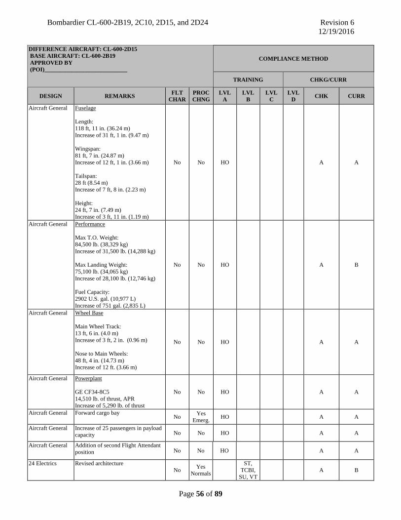
Bombardier CL-600-2B19, 2C10, 2D15, and 2D24 Revision 6 12/19/2016
Page 56 of 89
DIFFERENCE AIRCRAFT: CL-600-2D15 BASE AIRCRAFT: CL-600-2B19 APPROVED BY (POI)____________________________
COMPLIANCE METHOD
TRAINING CHKG/CURR
DESIGN REMARKS FLT CHAR
PROC CHNG
LVL A
LVL B
LVL C
LVL D CHK CURR
Aircraft General Fuselage Length: 118 ft, 11 in. (36.24 m) Increase of 31 ft, 1 in. (9.47 m) Wingspan: 81 ft, 7 in. (24.87 m) Increase of 12 ft, 1 in. (3.66 m) Tailspan: 28 ft (8.54 m) Increase of 7 ft, 8 in. (2.23 m) Height: 24 ft, 7 in. (7.49 m) Increase of 3 ft, 11 in. (1.19 m)
No No HO A A
Aircraft General Performance Max T.O. Weight: 84,500 lb. (38,329 kg) Increase of 31,500 lb. (14,288 kg) Max Landing Weight: 75,100 lb. (34,065 kg) Increase of 28,100 lb. (12,746 kg) Fuel Capacity: 2902 U.S. gal. (10,977 L) Increase of 751 gal. (2,835 L)
No No HO A B
Aircraft General Wheel Base Main Wheel Track: 13 ft, 6 in. (4.0 m) Increase of 3 ft, 2 in. (0.96 m) Nose to Main Wheels: 48 ft, 4 in. (14.73 m) Increase of 12 ft. (3.66 m)
No No HO A A
Aircraft General Powerplant GE CF34-8C5 14,510 lb. of thrust, APR Increase of 5,290 lb. of thrust
No No HO A A
Aircraft General Forward cargo bay No Yes
Emerg. HO A A
Aircraft General Increase of 25 passengers in payload capacity No No HO A A
Aircraft General Addition of second Flight Attendant position No No HO A A
24 Electrics Revised architecture No Yes
Normals ST,
TCBI, SU, VT
A B

Bombardier CL-600-2B19, 2C10, 2D15, and 2D24 Revision 6 12/19/2016
Page 57 of 89
DIFFERENCE AIRCRAFT: CL-600-2D15 BASE AIRCRAFT: CL-600-2B19 APPROVED BY (POI)____________________________
COMPLIANCE METHOD
TRAINING CHKG/CURR
DESIGN REMARKS FLT CHAR
PROC CHNG
LVL A
LVL B
LVL C
LVL D CHK CURR
27 Flight Controls Three panel slats on each wing Minor Yes
Normals ST,
TCBI, SU, VT
A A
49 APU Tailcone mounted No Minor
Normals HO A A
52 Doors Two forward cargo bay doors No Minor
Normals HO A A
52 Doors Two additional overwing emergency exits No No HO A A
Limitations APU operating limits; Engine parameters; Gear extension speed; Taxi turning radius; These are not all inclusive
No Yes Limits
ST, TCBI,
SU, VT B B
Limitations MMO above FL340 is 0.84M Decrease of 0.01 m
No Yes Limits HO A A

Bombardier CL-600-2B19, 2C10, 2D15, and 2D24 Revision 6 12/19/2016
Page 58 of 89
DIFFERENCE AIRCRAFT: CL-600-2D15 BASE AIRCRAFT: CL-600-2B19 APPROVED BY (POI)____________________________
COMPLIANCE METHOD
TRAINING CHKG/CURR
SYSTEM REMARKS FLT CHAR
PROC CHNG
LVL A
LVL B
LVL C
LVL D CHK CURR
21 ECS Recirculated air distribution system with fan control switch No Minor
Normals HO A A
21 ECS No dedicated fan for avionics bay cooling No Minor
Normals HO A A
21 ECS No dedicated standby fan for EFIS cooling. Backup cooling is via ECS airflow. No Minor
Normals HO A A
21 ECS Selected and actual temp displayed on ECS synoptic page No Minor
Normals HO A A
21 ECS Revised architecture. No dedicated cargo bay fan No No HO A A
21 ECS Revised architecture. One electrically operated outflow valve, two safety valves, one ground valve
No No HO A A
24 Electrics CB panels 3 and 4 removed; 40 kVA generator (no load shedding for failed generator); Generator switches (3) always left in AUTO; AC Utility buses removed; ACPC controls switching automatically; 4 - 120A TRUs instead of 5 - 100A TRUs; Bus Ties are automatic (controlled by DCPC). Switchlights removed on electrical power panel; Service bus powered from DC bus 2; One DC utility bus; DC external power plug and DC external switchlight removed; New ADG bus installed; AC Electric synoptic changes; ADC (no lamp test); Battery chargers, battery location.
No Minor Normals
ST, TCBI, SU, VT
B B
26 Fire/Ovht Simplified testing procedure. Automatic BITE and MDC interface No Minor
Normals HO A A
26 Fire/Ovht No jetpipe overheat detection No No HO A A 26 Fire/Ovht Fire suppression for forward cargo area.
Common Halon system used to supply both compartments. Three cargo smoke detectors.
No
Minor Normals HO A A
27 Flight Controls
No dedicated spoileron control surface. Multifunction spoilers act as flight spoiler or spoileron or ground lift dump.
No No
ST, TCBI, SU, VT
A A
27 Flight Controls
No flutter dampers on elevators No No HO A A
27 Flight Controls
Rudder limiter incorporated, function of speed and flap position controlled by SSCU
No No
ST, TCBI, SU, VT
A A
27 Flight Controls
Power up BITE test starts only when all three hydraulic systems are fully powered. A SPLR/STAB IN TEST advisory message
No Minor Normals HO A A

Bombardier CL-600-2B19, 2C10, 2D15, and 2D24 Revision 6 12/19/2016
Page 59 of 89
DIFFERENCE AIRCRAFT: CL-600-2D15 BASE AIRCRAFT: CL-600-2B19 APPROVED BY (POI)____________________________
COMPLIANCE METHOD
TRAINING CHKG/CURR
SYSTEM REMARKS FLT CHAR
PROC CHNG
LVL A
LVL B
LVL C
LVL D CHK CURR
is posted on EICAS during this test - All flt control systems are inoperative during the test
27 Flight Controls
For redundancy, emergency slat/flap switch added to drive slats to 20 degrees and flaps to 20 degrees with a slat/flap selector failure
No Yes
Abnormal
ST, TCBI, SU, VT
B B
27 Flight Controls
Slat/flap lever has 6 positions No Minor
Normals HO A A
28 Fuel No gravity refuel capability on center tank No Yes HO A A
28 Fuel Dedicated cross-flow pump No No HO A A
28 Fuel Bulk fuel temperature sensor in right main tank No No HO A A
28 Fuel Fuel synoptic changes No No HO A A
29 Hydraulics 1B/2B pump is not load shed when respective engine GEN is not operating No
Minor Abnorma
l HO A A
29 Hydraulics Thrust reversers are powered by hydraulics No No HO A A
29 Hydraulics Hydraulic SOV switches added to isolate EDP during low pressure condition without shutting down the engine No
Minor Normals Abnorma
l
ST, TCBI, SU, VT
B B
30 Ice and Rain No cowl anti-ice blowout plug on engines No Minor
Normals HO A A
30 Ice and Rain Revised architecture for cowl anti-icing duct leak detection in pylon area No
Minor New msg.
HO A A
30 Ice and Rain Simplified cowl and wing anti-ice synoptic page No No HO A A
30 Ice and Rain Air data probes and sensor anti-icing tested before flight with ICE DET switchlight No Minor
Normals HO A A
30 Ice and Rain Revised architecture for wing OVHT protection. No STBY mode for wing anti-ice required.
No No HO A A
30 Ice and Rain Windshield wiper has intermittent position. No No HO A A
30 Ice and Rain Variable white arcs on the N2 gauges. Range of arc varies with engine bleed condition. No No
ST, TCBI, SU, VT
B B
30 Ice and Rain Wing anti-ice system tested continuously. No test switch (automatic function) No Minor
Normals HO A A
32 Landing gear Nose doors are mechanical No No HO A A

Bombardier CL-600-2B19, 2C10, 2D15, and 2D24 Revision 6 12/19/2016
Page 60 of 89
DIFFERENCE AIRCRAFT: CL-600-2D15 BASE AIRCRAFT: CL-600-2B19 APPROVED BY (POI)____________________________
COMPLIANCE METHOD
TRAINING CHKG/CURR
SYSTEM REMARKS FLT CHAR
PROC CHNG
LVL A
LVL B
LVL C
LVL D CHK CURR
32 Landing gear Cantilever assemblies on main gear with shimmy dampers No Minor
Normals HO A A
32 Landing gear No main gear dust pin covers No No HO A A
32 Landing gear No FLT/NORM switch installed on forward external service panel No Minor
Normals HO A A
32 Landing gear No anti-skid test switch. Revised anti-skid test procedure. No Yes
Normals
ST, TCBI, SU, VT
B B
32 Landing gear NWS deflection is +/- 80 degrees with tiller and rudder pedal movement will deflect NW +/- 8 degrees
No No HO A A
32 Landing gear Increased tire speed limit No No HO A A
33 Lighting Overhead panel dome lights installed No No HO A A
33 Lighting Single nose landing light No No HO A A
33 Lighting Three exterior lights per side for emergency exit lighting No No HO A A
33 Lighting No EMER LTS OFF light on panel. EMER LTS OFF caution message only No
Minor Normals Abnorma
l
HO A A
34 Flight Instr. No mach transducer or selector valves in pitot static system No Minor
Normals HO A A
34 Flight Instr. One electronic integrated standby indicator provides airspeed, altitude, attitude, slip/skid, and localizer/glideslope information
No Minor Normals HO A A
35 Oxygen Overboard discharge indicator located on left side of fuselage No No HO A A
36 Pneumatics New flight deck bleed air panel. Engine bleed air taken from either 6th or 10th stage to supply common manifold. Bleed air selection is automatic when in AUTO mode. Provisions for manual switching.
No
Yes Normals
/ Abnorma
l
ST, TCBI, SU, VT
B B
36 Pneumatics Power On automatic bleed air leak detection test No Minor
Normals HO A A
49 APU 40 kVA generator; No APU intake door 'MID' EICAS indication; Dedicated APU fuel pump; APU Fuel supply, left collector tank; AVAIL light = ready for electrical loading, ECU determines when pneumatic loading is available;
No No
ST, TCBI, SU, VT
A B

Bombardier CL-600-2B19, 2C10, 2D15, and 2D24 Revision 6 12/19/2016
Page 61 of 89
DIFFERENCE AIRCRAFT: CL-600-2D15 BASE AIRCRAFT: CL-600-2B19 APPROVED BY (POI)____________________________
COMPLIANCE METHOD
TRAINING CHKG/CURR
SYSTEM REMARKS FLT CHAR
PROC CHNG
LVL A
LVL B
LVL C
LVL D CHK CURR
No fire horn; Start cycle.
52 Doors Four overwing emergency exits. Minor changes to doors synoptic page and EICAS messages
No Minor
Messages
HO A A
70 Powerplant FADEC controlled
No Minor Normals
ICBI, CSS, CPT, FTD 2-5
B B
70 Powerplant N1 and N2 sync control panel
No
Minor Normals Abnorma
l
HO A A
70 Powerplant FADEC controlled start cycle for ATS and windmill starts
No Minor Normals
ICBI, CSS, CPT, FTD 2-5
B B
70 Powerplant Thrust reversers hydraulically-actuated. No thrust lever retarder control system No No
ST, TCBI, SU, VT
B B
70 Powerplant No emergency stow PBAs
No Minor Normals
ST, TCBI, SU, VT
B B
70 Powerplant High power schedule PBA
No Yes
ST, TCBI, SU, VT
B B
70 Powerplant FADEC generated thrust limits for: (automatic with thrust levers in respective detent) Takeoff (TO) Flex (FLX) Climb (CLB) Go Around (GA) Max Continuous Thrust (MCT) Cruise (CRZ) – manually set in the cruise range
No No
ST, TCBI, SU, VT
B B
70 Powerplant Engine oil test panel removed. Engine oil level quantities provided on menu page No Minor
Normals HO A A

Bombardier CL-600-2B19, 2C10, 2D15, and 2D24 Revision 6 12/19/2016
Page 62 of 89
DIFFERENCE AIRCRAFT: CL-600-2D15 BASE AIRCRAFT: CL-600-2B19 APPROVED BY (POI)____________________________
COMPLIANCE METHOD
TRAINING CHKG/CURR
MANEUVER REMARKS FLT CHAR
PROC CHNG
LVL A
LVL B
LVL C
LVL D CHK CURR
AFCS Initial takeoff pitch is optimized to takeoff V speeds No No ST, TCBI,
SU, VT B B
Taxi Turning radius decreased No No HO A A
Takeoff Rotation rate is 3-5 degrees per second towards target FD No No HO A A
Takeoff Throttles placed in “TOGA” detent and thrust is set into N1 caret by FADEC. Throttles placed in “CLB” detent and trust is set into N1 caret by FADEC
No No CSS, PTT,
FTD 2-5 B B
Takeoff Flap retraction: Flaps 8 takeoff - Flaps retracted to ‘1’ from ‘8’ at V2 + 12 and to ‘0’ from ‘1’ at VT –15 kts. Flaps 20 takeoff – Flaps retracted to ‘8’ from ‘20’ at V2 + 12 and to ‘1’ from ‘8’ at V2 + 20 and then to ‘0’ from ‘1’ at VT –15 kts.
No Yes Normals
CSS, PTT,
FTD 2-5 C* B
Approach Approach Attitude Comparison CRJ200…………….CRJ705 Single Engine………Normal N/A…………………Flapless (Slats 20) Normal……………..Slatless (Flaps 45) Flapless…………….Single Engine
Yes No VT B A
Landing More pronounced flare Yes No VT B B

Bombardier CL-600-2B19, 2C10, 2D15, and 2D24 Revision 6 12/19/2016
Page 63 of 89
DIFFERENCE AIRCRAFT: CL-600-2B19 BASE AIRCRAFT: CL-600-2D15 APPROVED BY (POI)____________________________
COMPLIANCE METHOD
TRAINING CHKG/CURR
DESIGN REMARKS FLT CHAR
PROC CHNG
LVL A
LVL B
LVL C
LVL D CHK CURR
Aircraft General Fuselage Length: 87 ft, 10 in. (26.77 m) Decrease of 31 ft, 1 in. (9.47 m) Wingspan: 69 ft, 6 in. (21.21 m) Decrease of 12 ft, 1 in. (3.66 m) Tailspan: 20 ft, 4 in (6.20 m) Decrease of 7 ft, 8 in. (2.23 m) Height: 20 ft, 8 in. (6.30 m) Decrease of 3 ft, 11 in. (1.19 m)
No No HO A A
Aircraft General Performance Max T.O. Weight: 53,000 lb. (24,041 kg) Decrease of 31,500 lb. (14,288 kg) Max Landing Weight: 47,000 lb. (21,319 kg) Decrease of 28,100 lb. (12,746kg) Fuel Capacity: 2151 U.S. gal. (8,142 L) Decrease of 751 gal. (2,835L)
No No HO A A
Aircraft General Wheel Base Main Wheel Track: 10 ft, 4 in. (3.15 m) Decrease of 3 ft, 2 in, (0.96 m) Nose to Main Wheels: 36 ft, 4 in. (11.07 m) Decrease of 12 ft. (3.66 m)
No No HO A A
Aircraft General Powerplant GE CF34-3B1 9,220 lb. of thrust, APR Decrease of 5,290 lb. of thrust
No No HO A A
Aircraft General No forward cargo bay No Minor HO A A
Aircraft General Decrease of 25 passengers in payload capacity No No HO A A
Aircraft General One Flight Attendant position No No HO A A
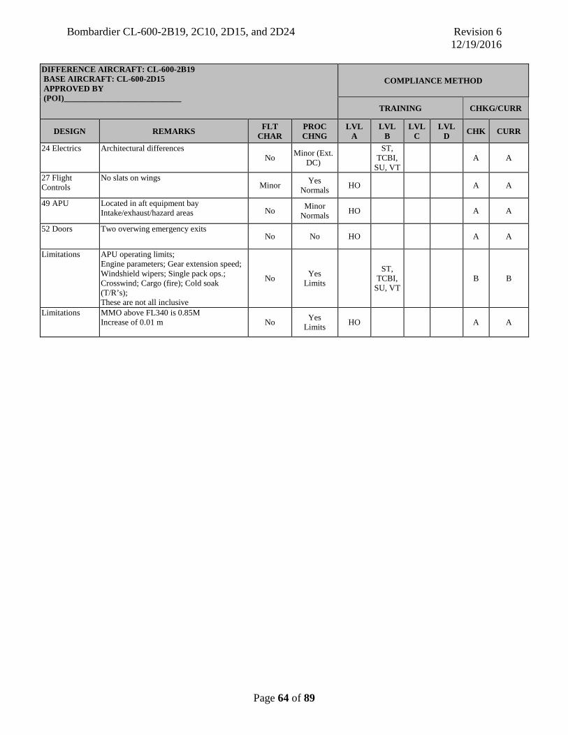
Bombardier CL-600-2B19, 2C10, 2D15, and 2D24 Revision 6 12/19/2016
Page 64 of 89
DIFFERENCE AIRCRAFT: CL-600-2B19 BASE AIRCRAFT: CL-600-2D15 APPROVED BY (POI)____________________________
COMPLIANCE METHOD
TRAINING CHKG/CURR
DESIGN REMARKS FLT CHAR
PROC CHNG
LVL A
LVL B
LVL C
LVL D CHK CURR
24 Electrics Architectural differences No Minor (Ext.
DC) ST,
TCBI, SU, VT
A A
27 Flight Controls
No slats on wings Minor Yes
Normals HO A A
49 APU Located in aft equipment bay Intake/exhaust/hazard areas No Minor
Normals HO A A
52 Doors Two overwing emergency exits No No HO A A
Limitations APU operating limits; Engine parameters; Gear extension speed; Windshield wipers; Single pack ops.; Crosswind; Cargo (fire); Cold soak (T/R’s); These are not all inclusive
No Yes Limits
ST, TCBI,
SU, VT B B
Limitations MMO above FL340 is 0.85M Increase of 0.01 m
No Yes Limits HO A A

Bombardier CL-600-2B19, 2C10, 2D15, and 2D24 Revision 6 12/19/2016
Page 65 of 89
DIFFERENCE AIRCRAFT: CL-600-2B19 BASE AIRCRAFT: CL-600-2D15 APPROVED BY (POI)____________________________
COMPLIANCE METHOD
TRAINING CHKG/CURR
SYSTEM REMARKS FLT CHAR
PROC CHNG
LVL A
LVL B
LVL C
LVL D CHK CURR
21 ECS No recirculation feature No Minor
Normals HO A A
21 ECS Dedicated avionics bay cooling system with fan control No Minor Normals
ST, TCBI,
SU, VT B A
21 ECS Cabin actual temperature indications only No Minor
Normals HO A A
21 ECS Dedicated cargo bay fan No Minor
Msg. HO A A
21 ECS Architectural differences: two pneumatically controlled outflow/safety valves overboard and inboard ground valves
No No HO A A
24 Electrics CB panels 3 and 4 on flight deck; 30 kVA generator (load shedding for failed generator); Generator switches (3) manually selected from OFF to ON after engine start; Two AC Utility busses, loadshed under certain conditions; No ACPC installed, individual relays accomplish switching; 5 - 100A TRUs instead of 4 - 120A TRUs; Bus Ties 1 and 2 are automatic. ESS Tie is manually selected. Switchlights on electrical power service panel; Service bus powered from SERV TRU; Two DC utility busses; DC external power plug with external DC switchlight on electrical panel; ADG feeds directly to AC essential bus; System affected during AC power transfer (loss of AC Bus 2). Battery chargers, Battery location.
No Minor Normals,
Abnormal, Emergency
ST,
TCBI, SU, VT
B B
26 Fire/Ovht Non-automated testing procedure.
No Yes Normals
ICBI, CSS, CPT, PTT,
FTD 2-5
C B
26 Fire/Ovht JETPIPE OVHT detection; Emergency Procedure (Recall) No Msg.
ST, TCBI,
SU, VT B B
27 Flight Controls
Dedicated spoileron control surface and dedicated flight spoiler control surface No No HO A A
27 Flight Controls
Flutter dampers on elevators No No HO A A
27 Flight Controls
No rudder limiter No No HO A A
27 Flight Controls
No power up BITE test or SPLR/STAB IN TEST advisory message No Minor
Normals HO A A
27 Flight Controls
No emergency flap switch No Yes Abnormal HO A A

Bombardier CL-600-2B19, 2C10, 2D15, and 2D24 Revision 6 12/19/2016
Page 66 of 89
DIFFERENCE AIRCRAFT: CL-600-2B19 BASE AIRCRAFT: CL-600-2D15 APPROVED BY (POI)____________________________
COMPLIANCE METHOD
TRAINING CHKG/CURR
SYSTEM REMARKS FLT CHAR
PROC CHNG
LVL A
LVL B
LVL C
LVL D CHK CURR
27 Flight Controls
Flap lever has 5 positions No Minor
Normals HO A A
28 Fuel Gravity refuel capability on center tank No Yes HO A A
28 Fuel Shared APU and crossflow fuel pump No No HO A A 28 Fuel Bulk fuel temperature sensor in left main
tank No No HO A A
29 Hydraulics 1B/2B pump is load shed when respective GEN is not operating No Minor
Abnormal HO A A
29 Hydraulics No hydraulic SOV switches No Minor
Abnormal HO A A
30 Ice and Rain
Cowl anti-icing valves pressure regulated with overpressure protection (Anti-ice blowout plug on engines)
No Minor Normals HO A A
30 Ice and Rain
Revised architecture for cowl anti-icing duct leak detection in pylon area No Minor HO A A
30 Ice and Rain
Air data probes and sensor anti-icing not tested No No HO A A
30 Ice and Rain
Wing anti-icing two operating temperature modes NORM and STBY are manually selectable
No Minor Abnormal ST,
TCBI, SU, VT
B A
30 Ice and Rain
Amber arcs on the N2 gauges. Range from 0 -78% No No HO A A
30 Ice and Rain
Wing anti-ice system test switch No Minor Normals
ST, TCBI,
SU, VT B B
30 Ice and Rain
Architectural differences on synoptic page No No HO A A
30 Ice and Rain
Cowl and wing anti-ice deactivated during thrust reverser deployment No No HO A A
32 Landing gear
Nose doors are powered by hydraulics No Minor Normals FTD 2-5 B A
32 Landing gear
Trailing link assemblies on main gear without shimmy dampers No No HO A A
32 Landing gear
Decreased tire speed limit No No HO A A
32 Landing gear
Main gear pin dust cover No Minor Normals HO A A
32 Landing gear
FLT/NORM switch on forward external service panel No Minor Normals
ST, TCBI,
SU, VT B A
32 Landing gear
Anti-skid test switch Parking brake OFF. No Yes
Normals ST,
TCBI, SU, VT
B A
32 Landing gear
NWS deflection is +/- 70 degrees with tiller and rudder pedal movement will deflect NW +/- 5 degrees
No No HO A A
33 Lighting No overhead panel dome lights No No HO A A

Bombardier CL-600-2B19, 2C10, 2D15, and 2D24 Revision 6 12/19/2016
Page 67 of 89
DIFFERENCE AIRCRAFT: CL-600-2B19 BASE AIRCRAFT: CL-600-2D15 APPROVED BY (POI)____________________________
COMPLIANCE METHOD
TRAINING CHKG/CURR
SYSTEM REMARKS FLT CHAR
PROC CHNG
LVL A
LVL B
LVL C
LVL D CHK CURR
33 Lighting Dual nose landing lights No No HO A A 33 Lighting Four exterior lights per side for
emergency exit lighting No No HO A A
33 Lighting EMER LTS OFF light on the EMER LTS panel illuminates coincident with the EMER LTS OFF caution message
No Minor Normals HO A A
34 Flight Instr. Mach transducer and selector valves in pitot static system No Minor
Abnormal HO A A
34 Flight Instr. Two separate standby instruments provide airspeed, altitude, attitude, slip/skid, and localizer/glideslope information
No Minor Normals
ST, TCBI,
SU, VT B B
35 Oxygen Overboard discharge indicator located on right side of fuselage No No HO A A
36 Pneumatics Thrust reversers are powered by 14th stage bleed air No No
ST, TCBI,
SU, VT B B
36 Pneumatics 10th and 14th stage bleed air systems controlled by manual manipulation of bleed air switches with APU interlock protection system
No Yes Normals
ICBI, CSS, CPT, PTT,
FTD 2-5
C B
36 Pneumatics 10th stage manifold services: air conditioning, engine starting. 14th stage manifold services: anti-ice systems. Single pack ops.
No Yes Abnormal
ST, TCBI,
SU, VT B B
36 Pneumatics Bleed air leak detection test conducted first flight of the day
No Yes Normals
ICBI, CSS, CPT, PTT,
FTD 2-5
C B
49 APU 30kVA generator; APU Intake Door EICAS Indications: CLSD, MID and OPEN; Shared APU and Crossflow fuel pump; Fuel supply, both wing tanks; AVAIL light = ready for pneumatic loading, APU GCU determines when electrical loading is available. Fire horn; start cycle.
No
Yes Normals
Abnormal Emergency
ST,
TCBI, SU, VT
B A
52 Doors Two overwing emergency exits Minor changes to doors synoptic page and EICAS messages
No Minor Messages HO A A
70 Powerplant Hydro-mechanical and N1 speed governing No No
ST, TCBI,
SU, VT A A
70 Powerplant APR and ENG SPEED control panel No Yes Normals
ST, TCBI,
SU, VT A A
70 Powerplant Thrust lever retarder control system No No
ST, TCBI,
SU, VT B B

Bombardier CL-600-2B19, 2C10, 2D15, and 2D24 Revision 6 12/19/2016
Page 68 of 89
DIFFERENCE AIRCRAFT: CL-600-2B19 BASE AIRCRAFT: CL-600-2D15 APPROVED BY (POI)____________________________
COMPLIANCE METHOD
TRAINING CHKG/CURR
SYSTEM REMARKS FLT CHAR
PROC CHNG
LVL A
LVL B
LVL C
LVL D CHK CURR
70 Powerplant Emergency stow PBAs for Thrust Reversers No Yes Normals
Emergency FTD 2-5 C B
70 Powerplant Pilot-managed start cycles for ATS and windmill starts No Yes
Normals HO A A
70 Powerplant FMS generated thrust limits for: manually set, no detents Takeoff (TO) Flex (FLX) Climb (CLB) GoAround (GA) Max Continuous Thrust (MCT) Cruise (CRZ)
No Minor Normals
ICBI, CSS, CPT, PTT,
FTD 2-5
C B
70 Powerplant High power schedule PBA No Yes HO A A
70 Powerplant Oil level test panel No Minor
Normals ST,
TCBI, SU, VT
B A

Bombardier CL-600-2B19, 2C10, 2D15, and 2D24 Revision 6 12/19/2016
Page 69 of 89
DIFFERENCE AIRCRAFT: CL-600-2B19 BASE AIRCRAFT: CL-600-2D15 APPROVED BY (POI)____________________________
COMPLIANCE METHOD
TRAINING CHKG/CURR
MANEUVER REMARKS FLT CHAR
PROC CHNG
LVL A
LVL B
LVL C
LVL D CHK CURR
AFCS FD target pitch attitude on takeoff is 15 degrees up and GA or SE takeoff is 10 degrees up
No No ST, TCBI, SU, VT B A
Taxi Turning radius decreased No No HO A A
Takeoff Rotation rate is 3 degrees per second towards target FD No No HO A A
Takeoff Throttles manually placed in thrust caret, set by FMS
No No
ICBI, CSS, CPT, PTT,
FTD 2-5
B B
Takeoff No Flap 1 position: no requirement to monitor Vt -15 airspeed for flap retraction from flap 8 to flap1
No Yes Normals
ICBI, CSS, CPT, PTT,
FTD 2-5
B B
Approach Approach Attitude Comparison CRJ705………………….CRJ200 Normal…………………..Single Engine Flapless (slats 20)……….N/A Slatless (flaps 45)……….Normal Single Engine……………Flapless
No No VT B B
Landing Minimal flare required No No ST, TCBI,
SU, VT B B

Bombardier CL-600-2B19, 2C10, 2D15, and 2D24 Revision 6 12/19/2016
Page 70 of 89
DIFFERENCE AIRCRAFT: CL-600-2D15 BASE AIRCRAFT: CL-600-2C10 APPROVED BY (POI)____________________________
COMPLIANCE METHOD
TRAINING CHKG/CURR
DESIGN REMARKS FLT CHAR
PROC CHNG
LVL A
LVL B
LVL C
LVL D CHK CURR
Aircraft General Fuselage Length: 118 ft, 11 in. (36.24 m) Increase of 12 ft, 3 in. (3.73 m) Wingspan: 81 ft, 7 in. (24.87 m) Increase of 5 ft, 4 in. (1.62 m) Tailspan: 28 ft. (8.54 m) No change Height: 24 ft, 07 in. (7.49 m) Decrease of 3 in. (0.08 m)
No No HO A A
Aircraft General Performance Max T.O. Weight: 84,500 lb. (38,329 kg) Increase of 9,500 lb. (4,309 kg) Max Landing Weight: 75,100 lb. (34,065 kg) Increase of 8,100 lb. (3,674 kg) Fuel Capacity: 2902 U.S. gal. (10,977 L) No change
No No HO A A
Aircraft General Wheel Base Main Wheel Track: 13 ft, 6 in. (4.0 m) No change Nose to Main Wheels: 48 ft, 4 in. (14.73 m) Increase of 7 ft, 6 in. (2.29 m)
No No HO A A
Aircraft General Powerplant GE CF34-8C5 14,510 lb. of thrust, APR Increase of 720 lb. of thrust
No No HO A A
Aircraft General Increase of 5 passengers in payload capacity No No HO A A
52 Doors Additional forward cargo bay doors (2 Total) No Minor
Normals HO A A
52 Doors Two additional overwing emergency exits (4 total)
No No HO A A
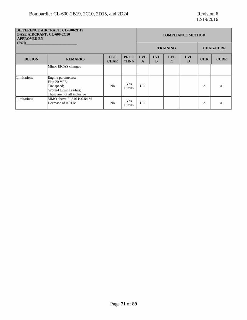
Bombardier CL-600-2B19, 2C10, 2D15, and 2D24 Revision 6 12/19/2016
Page 71 of 89
DIFFERENCE AIRCRAFT: CL-600-2D15 BASE AIRCRAFT: CL-600-2C10 COMPLIANCE METHOD APPROVED BY (POI)____________________________ TRAINING CHKG/CURR
DESIGN REMARKS FLT CHAR
PROC CHNG
LVL A
LVL B
LVL C
LVL D CHK CURR
Minor EICAS changes
Limitations Engine parameters; Flap 20 VFE; Tire speed; Ground turning radius; These are not all inclusive
No Yes Limits HO A A
Limitations MMO above FL340 is Decrease of 0.01 M
0.84 M No Yes
Limits HO A A

Bombardier CL-600-2B19, 2C10, 2D15, and 2D24 Revision 6 12/19/2016
Page 72 of 89
DIFFERENCE AIRCRAFT: CL-600-2D15 BASE AIRCRAFT: CL-600-2C10 APPROVED BY (POI)____________________________
COMPLIANCE METHOD
TRAINING CHKG/CURR
SYSTEM REMARKS FLT CHAR
PROC CHNG
LVL A
LVL B
LVL C
LVL D CHK CURR
Aircraft General
Larger winglets No No HO A A
27 Flight Controls
New slat/flap 20 relationship. When flap 20 selected, slats are 20 degrees
No No HO A A
27 Flight Controls
When emergency slats/flaps switch selected, slats are driven to 20 degrees and flaps to 20 degrees
No No HO A A
32 Landing gear
Tire speed increased No No HO A A

Bombardier CL-600-2B19, 2C10, 2D15, and 2D24 Revision 6 12/19/2016
Page 73 of 89
DIFFERENCE AIRCRAFT: CL-600-2D15 BASE AIRCRAFT: CL-600-2C10 APPROVED BY (POI)____________________________
COMPLIANCE METHOD
TRAINING CHKG/CURR
MANEUVER REMARKS FLT CHAR
PROC CHNG
LVL A
LVL B
LVL C
LVL D CHK CURR
Taxi Increased taxi turning radius No No HO A A
Landing More pronounced flare No No HO A A

Bombardier CL-600-2B19, 2C10, 2D15, and 2D24 Revision 6 12/19/2016
Page 74 of 89
DIFFERENCE AIRCRAFT: CL-600-2C10 BASE AIRCRAFT: CL-600-2D15 APPROVED BY (POI)____________________________
COMPLIANCE METHOD
TRAINING CHKG/CURR
DESIGN REMARKS FLT CHAR
PROC CHNG
LVL A
LVL B
LVL C
LVL D CHK CURR
Aircraft General
Fuselage Length: 106 ft, 8 in. (32.51 m) Decrease of 12 ft, 3 in. (3.73 m) Wingspan: 76 ft, 3 in. (23.24 m) Decrease of 5 ft, 4 in. (1.62 m) Tailspan: 28 ft, 0 in. (8.54 m) No change Height: 24 ft, 10 in. (7.57 m) Increase of 3 in. (0.08 m)
No No HO A A
Aircraft General
Performance Max T.O. Weight: 75,000 lb. (34,020 kg) Decrease of 9,500 lb. (4,309 kg) Max Landing Weight: 67,000 lb. (30,390 kg) Decrease of 8,100 lb. (3,674 kg) Fuel Capacity: 2902 U.S. gal. (10,977 L) No change
No No HO A A
Aircraft General Wheel Base Main Wheel Track: 13 ft, 2 in. (4.0 m) No Change Nose to Main Wheels: 40 ft, 10 in. (12.44 m) Decrease of 7 ft, 6 in. (2.29 m)
No No HO A A
Aircraft General Powerplant GE CF34-8C1 or GE CF34-8C5B1 13,790 lb. of thrust, APR Decrease of 720 lb. of thrust
No No HO A A
Aircraft General Decrease of 5 passengers in payload capacity No No HO A A
52 Doors One forward cargo bay door No Minor
Normals HO A A
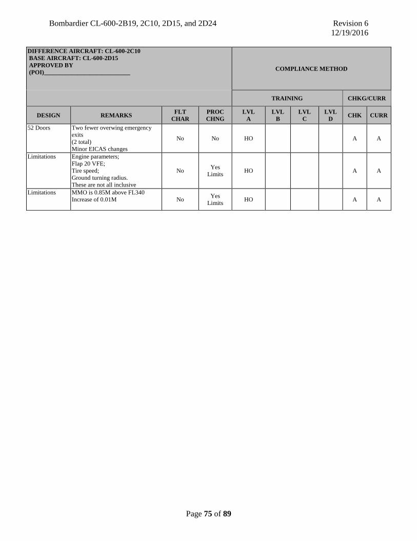
Bombardier CL-600-2B19, 2C10, 2D15, and 2D24 Revision 6 12/19/2016
Page 75 of 89
DIFFERENCE AIRCRAFT: CL-600-2C10 BASE AIRCRAFT: CL-600-2D15 APPROVED BY (POI)____________________________ COMPLIANCE METHOD
TRAINING CHKG/CURR
DESIGN REMARKS FLT CHAR
PROC CHNG
LVL A
LVL B
LVL C
LVL D CHK CURR
52 Doors Two fewer overwing emergency exits (2 total) Minor EICAS changes
No No HO A A
Limitations Engine parameters; Flap 20 VFE; Tire speed; Ground turning radius. These are not all inclusive
No Yes Limits HO A A
Limitations MMO is 0.85M above FL340 Increase of 0.01M
No Yes Limits HO A A

Bombardier CL-600-2B19, 2C10, 2D15, and 2D24 Revision 6 12/19/2016
Page 76 of 89
DIFFERENCE AIRCRAFT: CL-600-2C10 BASE AIRCRAFT: CL-600-2D15 APPROVED BY (POI)____________________________
COMPLIANCE METHOD
TRAINING CHKG/CURR
SYSTEM REMARKS FLT CHAR
PROC CHNG
LVL A
LVL B
LVL C
LVL D CHK CURR
Aircraft General Smaller winglets No No HO A A
27 Flight Controls
New slat/flap 20 relationship. When flap 20 selected, slats are 25 degrees
No No HO A A
27 Flight Controls
When emergency slats/flaps switch is selected, the slats are driven to 25 degrees and flaps to 20 degrees
No No HO A A
32 Landing gear Tire speed reduced No No HO A A

Bombardier CL-600-2B19, 2C10, 2D15, and 2D24 Revision 6 12/19/2016
Page 77 of 89
DIFFERENCE AIRCRAFT: CL-600-2C10 BASE AIRCRAFT: CL-600-2D15 APPROVED BY (POI)____________________________
COMPLIANCE METHOD
TRAINING CHKG/CURR
MANEUVER REMARKS FLT CHAR
PROC CHNG
LVL A
LVL B
LVL C
LVL D CHK CURR
Taxi Decreased taxi turning radius No No HO A A
Landing Less pronounced flare No No HO A A

Bombardier CL-600-2B19, 2C10, 2D15, and 2D24 Revision 6 12/19/2016
Page 78 of 89
DIFFERENCE AIRCRAFT: CL-600-2D24 BASE AIRCRAFT: CL-600-2D15 APPROVED BY (POI)____________________________
COMPLIANCE METHOD
TRAINING CHKG/CURR
DESIGN REMARKS FLT CHAR
PROC CHNG
LVL A
LVL B
LVL C
LVL D CHK CURR
Aircraft General
Increase of 15 passengers in payload capacity No No HO A A
Aircraft General
Decrease of 15 passengers in payload capacity No No HO A A

Bombardier CL-600-2B19, 2C10, 2D15, and 2D24 Revision 6 12/19/2016
Page 79 of 89
APPENDIX 3
COMPLIANCE CHECKLIST (CL-600-2B19)
The prototype aircraft, serial number 7003, which the FSB evaluated on November 2-5, 1992, was not fully representative of an U.S. production version airplane. Therefore, the FSB was unable to determine compliance with applicable part 91 and 121 operating requirements at that time. In November 1993, Canadair submitted a checklist to the FSB indicating how the aircraft complies with parts 91 and 121. The FSB was not able to validate that checklist. The checklist is available on request from the Long Beach AEG and is included it in this report for informational purposes only.

Bombardier CL-600-2B19, 2C10, 2D15, and 2D24 Revision 6 12/19/2016
Page 80 of 89
APPENDIX 4
COMPLIANCE CHECKLIST (CL-600-2C10)
Results of the evaluation conducted on serial number10004 on November 3, 2000. The checklist is available on request from the Long Beach AEG. It is provided for informational purposes only.
Bombardier CL-600-2B19, 2C10, 2D15, and 2D24 Revision 6 12/19/2016
Page 81 of 89
APPENDIX 5
COMPLIANCE CHECKLIST (CL-600-2D24)
These are the results of a physical evaluation conducted by the FSB on CL-600-2D24, serial number 15001, on October 7, 2002, in Wichita, KS. It must be noted that at the time of the evaluation, the CL-600-2D24 had received a Transport Canada Type Certificate, but had not yet started FAA Type Certification flight-testing, and therefore, did not hold an FAA Type Certificate. This explains most of the “Does not comply” or “Not demonstrated” FSB findings herein.
In November 2002, the CL-600-2D24 received an FAA Type Certificate. Bombardier then submitted updated positions to the FSB on many of the “Does not comply” or “Not demonstrated” items. Those updated items are identified in this Appendix with an asterisk “*”. Bombardier’s updated positions are listed in Appendix 6. The FSB did not validate Appendix 6, but has included it for informational purposes only. The checklist is available on request from the Long Beach AEG. It is provided for informational purposes only.
Please see section 9 of this report for more information on this checklist.

Bombardier CL-600-2B19, 2C10, 2D15, and 2D24 Revision 6 12/19/2016
Page 82 of 89
APPENDIX 6
BOMBARDIER UPDATE TO COMPLIANCE CHECKLIST (CL-600-2D24)
In November 2002, the CL-600-2D24 received an FAA Type Certificate. Bombardier then submitted updated positions to the FSB on many of the “Does not comply” or “Not demonstrated” items listed in Appendix 5. Those updated items are asterisked “*” in Appendix 5 and are listed in this Appendix. The FSB did not validate this Appendix, but has included it for informational purposes. The checklist is available on request from the Long Beach AEG. It is provided for informational purposes only.

Bombardier CL-600-2B19, 2C10, 2D15, and 2D24 Revision 6 12/19/2016
Page 83 of 89
APPENDIX 7
HEAD-UP GUIDANCE SYSTEM (HGS) CL-600-2B19 CL-600-2C10 CL-600-2D15 CL-600-2D24
Background.
Head-up Guidance System (HGS) – CL-600-2B19 Only.
The Flight Dynamics HGS was evaluated by the FSB, in April 1996. Only the IIIa approach mode was certified. Takeoff, climb, cruise, descent, and VMC modes were not certified. In 2001, Rockwell Collins/Flight Dynamics applied to the FAA, and received STC #SA2930NY-T, for what they called a “Phase II” HGS. This Phase II HGS added all phases of flight functions to the previously approved HGS. The FSB conducted an evaluation of the Phase II HGS in April 2001 and found it operationally acceptable.
Head-up Guidance System (HGS) – CL-600-2C10 Only.
In 2001, Rockwell Collins/Flight Dynamics also applied to the FAA for an STC for an HGS on the CL6002C10. STC #ST8557LA-T was issued in 2002 after the FSB conducted an evaluation.
Head-up Guidance System (HGS) – CL-6002D15 and CL-6002D24 Only.
In 2005, Rockwell Collins/Flight Dynamics applied to the FAA for an STC for a HGS on the CL-600-2D15 and CL-600-2D24. STC #ST01390LA was issued in July 2006 after the FSB conducted an evaluation. The Rockwell Collins/Flight Dynamics Model 4200 Head-Up Guidance System (HGS) is approved for use during all phases of flight. The HGS has been shown to meet the requirements for Category III approach, landing, and rollout contained in FAA AC 120-28D. It also meets the requirements of FAA AC 120-28D as a primary reference aid for Low Visibility Takeoff (LOVTO) when Litton LTN-101 IRUs are installed. In December 2006, Rockwell Collins requested that the FAA certificate Improved Symbology for the Rockwell Collins 4200 HGS Takeoff Pitch Target and for LVTO with Honeywell Lazeref V installed. An FSB evaluation was conducted using the improved Symbology and the Honeywell Lazeref V for LVTO. It was found during the evaluation that the requirements of FAA AC 120-28D as a primary reference aid for Low Visibility Takeoff (LOVTO) were met. A revision to STC #ST01390LA was issued to Rockwell Collins in May 2007.

Bombardier CL-600-2B19, 2C10, 2D15, and 2D24 Revision 6 12/19/2016
Page 84 of 89
Head-Up Guidance System (HGS) Training Program.
NOTE: Criteria listed below apply to the CL-600-2B19 (Original and Phase II) and the CL-600-2C10, CL-600-2D15, and CL-600-2D24 Rockwell Collins/Flight Dynamics HGS. In the case of the CL-600-2C10, CL-600-2D15, and CL-600-2D24 HGS, special emphasis should be placed on the ground roll guidance comparison with the localizer deviation scale. It is possible, under some circumstances, for the ground roll guidance symbol to be on the left side of the HGS display and for the localizer deviation scale to be on the right side of the HGS display. It is important that a pilot be able to quickly determine his location on the runway.
The HGS pilot training requirements consists of those related to initial and recurrent ground and flight training. Unless covered concurrently during an initial or transition type rating course, a prerequisite to beginning this course of training is prior training, qualification, and currency in the CL-600-2B19 or CL-600-2C10. It should be noted that the program focuses principally upon training events flown in the left seat by the pilot-in-command (PIC) in 14 CFR part 121 operations. Nevertheless, second in command indoctrination and training is also essential.
1. Initial Ground Training. For airline operators, initial training should be conducted in accordance with the applicable provisions of part 121, §§ 121.415, 121.419, 121.424, and 121.427, FAA AC 120-28D, and the airline operation specifications. For all operators, the initial ground training program should include the following elements:
A. Classroom instruction covering HGS operational concepts, crew duties and responsibilities, and operational procedures, including preflight, normal, and non-normal pilot activities. For operators wishing credit for low visibility operations predicated on use of the HGS, information should be provided on the operational characteristics, capabilities, and limitations of the ground facilities (surface movement guidance control system) and airborne CAT III system. Airline policies and procedures concerning low visibility operations should include a reporting process, MEL issues, operation following a missed approach, OE, and currency requirements.
B. Classroom instruction (or Computer-Based Training (CBT)) on the HGS symbology set and its interrelationship with airplane aerodynamics, inertial factors, and environmental conditions.
C. An HGS pilot training manual or equivalent material in the Operations Manual which explains all modes of operation, the use of various HGS controls, clear descriptions of HGS symbology, including limit conditions and failures, and incorporating a crew procedures guide clearly delineating pilot-flying (PF) and pilot monitoring (PM) duties, responsibilities, and procedural call-outs and responses during all phases of flight during which HGS operations are anticipated. Emphasis on the availability and limitations of visual cues encountered on approach both before and after DH. This would include:
• Procedures for unexpected deterioration of conditions to less than minimum RVR encountered during approach, flare, and rollout.

Bombardier CL-600-2B19, 2C10, 2D15, and 2D24 Revision 6 12/19/2016
Page 85 of 89
• Demonstration of expected visual references with weather at minimum conditions.
• Expected sequence of visual cues during an approach in which visibility is at or above landing minima.
D. A multimedia system capable of a dynamic real-time demonstration of all modes of operation complete with sound. For operators wishing credit for low visibility operations predicated on use of the HGS, this should include narrative descriptions and several low weather approach demonstrations with procedural call-outs and responses. All critical procedural call-out possibilities should be covered.
E. If the HGS is used as a CAT II/CAT III landing system, emphasis on the need for rigorous crew discipline, coordination, and adherence to procedural guidelines as is required for other CAT II/CAT III landing systems.
2. Initial Flight Training. Unless integrated with initial or transition type rating training, flight training dedicated to HGS familiarization and proficiency is in addition to other required elements. For 14 CFR part 121 operators, initial flight training should be conducted in accordance with the applicable provisions of § 121.424. When an FFS is used, only FAA approved CL-600-2B19 or CL-600-2C10 (changeable to CL-600-2D15 and or CL-600-2D24) FFSs with both a visual and the Heads-Up Guidance System installed may be used. For flight simulator training, all required approaches should be flown from no closer than the final approach fix (FAF) for instrument approaches and from no closer than approximately 1,000 feet AGL (3–4 NM) to the runway threshold for visual approaches.
The following flight training program is generic in nature and should not be construed to dictate what the flight course of instruction must consist of. Each operator has its own unique requirements, route structure, fleet composition, and operations policies to consider in developing its training program. Therefore, what follows might be considered as a guide to an operator who is tailoring an HGS training program to fit his or her own needs.
A. Airwork. Airwork should include:
• Straight and level flight, accelerations, and decelerations. • Normal and steep turns, climbs, and descents. • Stall prevention and recovery and unusual attitudes. • Vectors to intercept and track selected VOR courses. • For aircraft with 4000 series HGS, include TCAS events and ground
proximity events.
NOTE: Emphasis should be placed on HGS unique symbology (i.e., flight path, flight path acceleration, airspeed error tape, AOA limit bracket, and excessive pitch chevrons). When this training is complete, the trainee should have a thorough understanding of the relationship between aircraft flight path parameters and the HGS symbology.

Bombardier CL-600-2B19, 2C10, 2D15, and 2D24 Revision 6 12/19/2016
Page 86 of 89
B. Visual Approaches (VMC mode):
• Perform multiple “night visual” approaches with the HCP set to different slope angles.
• Straight-in landings, no wind, repeat with 15 kt cross wind and at night. • Circling approaches only if authorized by OpSpec or at 1000 and 3 with a
10 kt cross wind.
NOTE: It is desirable to fly half of these approaches at different airports that have dissimilar approach and runway lighting systems. Special emphasis should be placed on optimizing circling approach techniques and procedures. Approaches with the aircraft in a non-normal flap configuration should be included.
C. Instrument Approaches.
a) For all operators:
• Perform approach to operators approved CAT I approach minimums with wind set at max authorized.
• Demonstrate failures and incorrect settings on approach (i.e., miss-set runway elevation, airspeed, selected course).
• Illustrate unique characteristics of symbology in wind shear conditions (i.e., erratic wind speed and direction, flight path, flight path acceleration, and speed error).
• Non-precision approaches to the operators lowest approved non-precision approach minima with a 15 kt cross wind.
b) For operators wishing credit for low visibility operations predicated on use of the HGS:
• Perform CAT II and/or CAT III (if operator is authorized CAT III) approaches to the operator’s lowest minima authorized with 10 kt cross wind.
• CAT III ILS flown to the lowest RVR and DH minimums authorized with a 10 knot crosswind.
• CAT III ILS with 0/0 weather. After touchdown, raise weather to demonstrate position on runway.
• CAT III ILS with various reasons for a missed approach (system downgrade, “APCH WARN”, etc.).
• CAT III ILS with various RVRs and crosswinds, include light turbulence. • Approach to CAT III minimums, with a go-around at minimums and
subsequent failure of HGS symbology.
NOTE: Several of the instrument approaches should include a variety of ground and airborne system failures requiring pilot recognition and appropriate procedural actions. Demonstrate system/component failures could include flap asymmetry problems, engine out operations, HGS sensor failures, etc.
Bombardier CL-600-2B19, 2C10, 2D15, and 2D24 Revision 6 12/19/2016
Page 87 of 89
Demonstration how HGS failure modes can reduce precision and increase pilot workload unless PF/PM duties and responsibilities are clearly delineated and understood.
D. Takeoff. For operators wishing credit for Low Visibility Takeoff (LOVTO) operations predicated on use of the HGS:
• Normal takeoff, clear, and calm, repeated with gusty winds. • Crosswinds should be trained to the max authorized (15 kts). • Takeoff, 600 foot RVR, with crosswind. • Takeoff, 300 foot RVR, with crosswind engine failure prior to V1. • Takeoff, 300 foot RVR with crosswind, engine failure after V1. • Takeoff with HGS failure, 300 foot RVR. • Takeoff at 300 foot RVR with HGS failure after V1 (so the pilot continues the
takeoff without HGS information).
The applicant must complete five CAT III approaches to CAT III minimums under the supervision of an authorized check pilot. An additional five approaches must be completed within 60 days of completion of those observed by the check pilot. All previously qualified (in aircraft) pilots should be certified upon satisfactory completion of the HGS ground and flight training programs.
All initial, upgrade, and transition PICs must be observed by a check pilot during their OE. This requirement should include three HGS assisted takeoffs: one visual approach and three instrument approaches in conditions not less than 1,800 foot RVR.
• For all operators; prior to utilizing the HGS for approach operations in IMC conditions below 1,800 foot RVR, each PIC must accomplish at least 10 approaches to Category II/III minima in weather conditions which are not less than published straight-in Category I minima. Each approach must terminate in a manually controlled HGS assisted landing or HGS assisted go-around. Of these 10 approaches, a minimum of five must be accomplished under the observation of a check pilot.
• Prior to utilizing the HGS for takeoff operations in IMC conditions below 500 foot RVR, each PIC must accomplish at least 10 HGS assisted takeoffs in weather conditions which are not less than 500 foot RVR. Of these 10 takeoffs, a minimum of five must be accomplished under the observation of a check pilot.
Bombardier CL-600-2B19, 2C10, 2D15, and 2D24 Revision 6 12/19/2016
Page 88 of 89
CURRENCY REQUIREMENTS
For operators wishing credit for low visibility operations on use of the HGS, during the 6 month recurrent training and proficiency checks, the following low visibility operations should be performed in addition to regular requirements:
• One approach conducted to CAT III minimums with a landing at the lowest authorized minima, crosswind 15 kts.
• One approach to CAT III minimums with a missed approach at 50 feet DH and loss of HGS on the go around.
• If using a 4000 Series HGS, and OpSpec authorizes single engine CAT III approach operations, one approach must be conducted with one engine inoperative to CAT III minima.
• One takeoff at the lowest authorized HGS minimums with an abort prior to V1. • One takeoff at lowest authorized HGS minimums with an engine failure after V1.

Bombardier CL-600-2B19, 2C10, 2D15, and 2D24 Revision 6 12/19/2016
Page 89 of 89
APPENDIX 8
Appendix 8 identifies regulatory training requirements which are not applicable to the Bombardier CL 600-2B19, 2C10, 2D15, and 2D24. Additionally, Seat Dependent Task Training is identified.
All training requirements in 14 CFR part 121, §§ 121.417, 121.419(a)(2), and part 121 appendix E apply to the Bombardier CL-600-2B19, 2C10, 2D15, and 2D24 aircraft except as follows:
• Emergency Training. Removal from the airplane (or training device) of each type of life raft, if applicable. No substitute, not installed on aircraft.
• Emergency Training. Transfer of type of slide/raft pack from one door to another. No substitute, not installed on aircraft.
• Emergency Training. Deployment, inflation, and detachment from the airplane (or training device) of each type of slide/raft pack and emergency evacuation including the use of a slide. No substitute, not installed on aircraft.
• Ground Training. Propeller training. No substitute, propeller not installed on aircraft. • Ground Training. Operations of systems and controls at the Flight Engineers station.
No substitute, not installed on aircraft. • Flight Training. Operations of systems and controls at the Flight Engineers station.
No substitute, Flight Engineers station not installed. • Flight Training. No substitute, Fuel Jettisoning system not installed on aircraft.
Seat Dependent Task Training:
• Pilots must receive training in these seat dependent tasks:
1. Left Pilot Seat. Taxiing the aircraft using the tiller from the left seat.