Embed Size (px)
Citation preview

FLEXURAL BEHAVIOR OF POST-TENSIONED MASONRY WALLS SUBJECIED TO
OlIT-OF PLANE LOADS: PRELIMINARY RESULTS
Robeno Rodriguez. (1), Ahmad A. Hamid (2), and Jesus Larralde (3)
1.ABSTRACI'
The idea of prestressing masonry elements to improve their structural behavior staned in
the nineteenth century, but it was not until the past two decades when a number of
investigations and applications were implemented demonsrrating the diverse benefits of
prestressed masonry. Considerable amount of studies have been carried out to explain the
behavior of masonry walls under out-of-plane loads, but no consistent method has yet been
developed to describe the state of stresses in the tendons and in the masonry near ultimate
load conditions. This paper presents preliminary results from experimental work being
carried out at Drexel University on the behavior and strength of post-tensioned hollow
masonry waJ1 segments subjected to out-of-plane load. It is concluded that post-tensioning
is an effective way of increasing cracking moment and ultimate strength of masonry waJ1s.
Keywords: Flexure, Out-of-plane loads, Masonry Walls, Post-tensioning, Prestress,
Unbonded tendons.
(1) M.S. studem, Drexel University, Philadelphia. PA 19104.
(2) Professor and Head, Departmem of Civil Engineering United AIab Emirates University, AI·Ain, UAE.
On leave from Drexel University, PhiJadelphia, PA 19104.
(3) Assistam Professor, Civil and Architectural Engrg. Dept., Drexel University, PhiJadelphia, PA. 19104.
597

2. INTRODUCTION
Because load bearing masonry buildings incorporate both the load bearing structural
system and the architectural function, economy and efficiency can be utilized. The structural integrity of load bearing masonry depends on the methods employed to
overcome the inherent low tensile strength. Low tensile strength can be overcome by either reinforcing or prestressing.
The use of prestressed masonry started in the nineteenth century, but it was not until the
past two decades when a considerable number of investigations and applications were
implemented in United Kingdom and New Zealand. Studies have shown that post
tensioning increases both horizontal [1] and vertical out-of-plane flexural strengths of masonry [2]. It has also been shown to increase the integrity and stiffness of post
tensioned masonry walls subjected to out-of-plane loads [3], and to limit the extent of cracking. The use of guided tendons has been demonstrated to increase the ductility and
strength of post-tensioned masonry walls [4].
The applications of post-tensioned masonry are very diverse. Post-tensioning has been used to overcome tensile stresses due to wind forces (5,6], seismic forces, and differentiaI
movement of foundations [7]. It has also been used to strengthen existing unreinforced masonry buildings, with emphasis in seisrnic upgrading [8]. Actual examples can be found
in buildings, retaining walls [9,10], bridge abutrnents [9], grain silos (11], etc.
A considerable amount of studies have been carried out to explain the behavior of masonry
walls under out-of-plane loads. They have generally concluded that post-tensioned
masonry walls behave essentially elastic until cracking, followed by a nonlinear behavior
until failure . The analysis of the post-cracking stage has been based, in the case of bonded
tendons, on the strain compatibility between masonry and tendon. For unbonded tendons, empirical formulas developed for concrete structures have been used, or a factor
multiplying the masonry strain is introduced to determine the strain in the reinforcement [12]. The British Code BS 5628 [13] gives a linear function to calculate the stress in the
tendon at the design moment of resistance. Recently, the Masonry Standards Joint Committee (MSJC) has proposed a fonnula to determine the stress of the unbonded tendon
at ultimate condirions [14] ; this fonnula is the same as that in the European masonry code EC6 [15] . As suggested by Schultz and Scalforo [16], research work is necessary to
describe the state of stresses in the tendons and in the masonry near ultimate load conditions, if a reliable analysis of flexural strength is to be developed.
598

The results presemed herein are part of a comprehensive program that is being carried out at
Drexel University to experimentally study the behavior and strength of post-tensioned
masonry walls subjected to out-of-plane loads. The parameters introduced in the tests
include the levei of prestress in the tendon, reinforcemem ratio p, and the fixity of the
tendon inside the cell (guided vs. unguided) . A total of four walls are planned to be tested.
Preliminary results from the frrst wall test are presented in this paper.
3. EXPERIMENTAL PROCEDURE
3.1 Material Propenies
The properties of the materiais used in this test program are shown in Table 1. The physical and mechanical propenies of the 150mm x 200mm x 400mm (6 in . x 8 in. x
16in.) blocks were obtained in accordance with ASTM Standards . The compressive strengths of the blocks were detennined following ASTM C140-75 procedures. Type S
monar was used in the construction of the wall. The compressive strength of the monar
was determined following ASTM Standard C190-80 for 51 mm (2 in.) cubes.
A total of four 2 course prisms were built in stack pattem with faceshell monar bedding in order to detennine masonry compressive strength and Modulus of Elasticity. The prisms
were capped with gypsum cemem and tested under axial compression following ASTM E447. The axial deformation was measured with two LVDTs to obtain the stress-strain
characteristics. The tensile strength of the prisms was detennined using a Bond Wrench set up similar to the one described in ASTM C1072. The tensile and stress-strain
characteristics of the steel bars were detennined following the ASTM AA3700.
Table I. Material Properties
Masonry Comp. Strength f'm Masonry Tensile Strength f't Masonry Modulus of Elasticity Blocks Compressive Strength Mortar Strength Steel Tensile Strength fpu Steel Modulus of Elasticity
599
19.09 MPa (2,770 psi) 0.28 MPa (42 psi) 18.11 Gpa ( 2,627.8 Ksi) 25 .62 MPa (3717 psi ) 22 MPa (3,192 psi) 825.4 MPa (119,730 psi) 18.2 Gpa ( 26 ,590. Ksi)

3.2 Wall Specirnen
The ful! scale wal! specimen was constructed by an experienced mason using 150mm x
200mm x 400mm (6 in . x 8 in . x 16in.) hollow concrete blocks. The specimen was composed of one and a half block wide and eight blocks in height. Mortar was placed only
in the faceshel!s . A high-strength, threaded reinforcing bar was placed in the center of the section as shown in Fig. 1. The bar was anchored at the bottom using a steel plate
embedded in a concrete beam.
The threaded steel bar was guided by metal ties placed in the joints every other course. A concrete beam was cast at the top of the specimen to transrnit the prestressing load from the
bar to the blocks. A steel tube was used to prevent bonding of the grout to the steel bar. AIso, a steel mesh was placed under the top beam to prevent leakage of the grout into the
wall.
254 mm (1 in.)steel plete
Reinf. Concrete Beam I
· . . . .
· .... -...
· . . . .
Tie ~
Threaded Steel Bar
304mm (12 in.)
1052mm (54 in.)
254 mm (1 in.)steel plete
. . . .. . ..
Nut
Threaded Steel Bar
Tie
0-0 Reinf. Concrete Beam
304mm (12in.)
Fig. 1 Test Specimen
3.3 Test Set Up and Loading System
The specimen was tested horizontally applying two concentrated line loads at 1/3 and 2/3 of the span. The wall was supported on a very súff box secúon steel beam. A roller support
and a hinge support were used to provide simply supponed conditions. This set up
produced a constant moment region that contained three central mortar joints. (See Fig. 2).
600
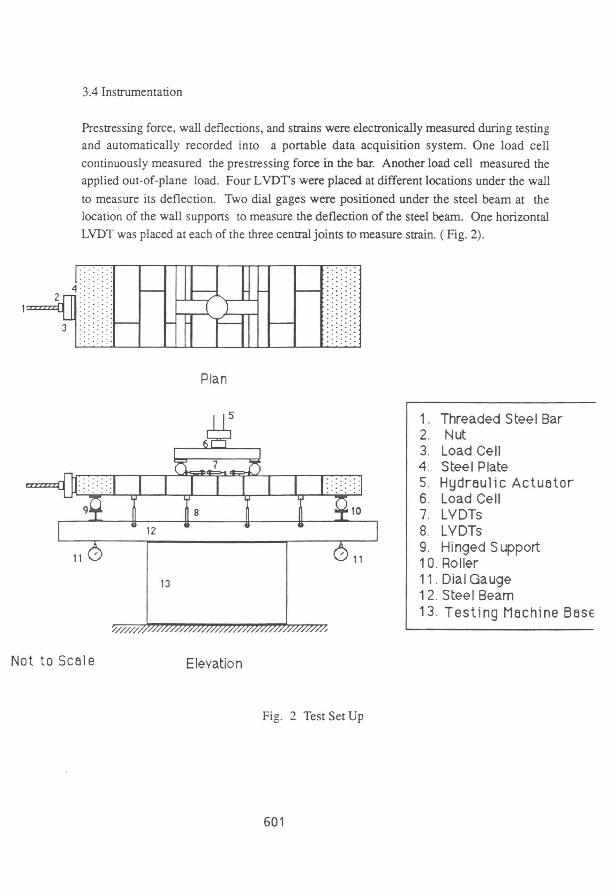
3.4 Instrumentation
Prestressing force, waIl deflections, and strains were electronicaIly measured during testing and automaúcally recorded into a portable data acquisition system. One load cell
continuously measured the prestressing force in the bar. Another load cell measured the applied out-of-plane load. Four L VDTs were placed at different locaúons under the waII
to measure its deflection. Two dial gages were positioned under the steel beam at the location of the waII suppons to measure the deflection of the steel beam. One horizontaI
LVDT was placed at each Df the three centraI joints to measure strain. ( Fig. 2) .
3 ..
Plan
1. Threaded Steel Bar 2. Nut 3. Load Cell 4. Steel Plate 5. Hydn~ulic Actuator 6. Load Cell 7. LVDTs 8. LVDTs 9. Hinged S upport 10 . Roller
13 11 . Dial Gauge 12. Steel Beam 13. Testing Machine Base
/'/////,
NottoScôle Elevation
Fig. 2 Test Set Up
601

3.5 Prestressing Application
After the specimen was built and cured for a minimum of 28 days. A fraction of the post
tensioning force was applied to the specimen to be able to move it to a horizontal position.
The post-tensioning force was applied following a technique commonly used in the United
Kingdom [7] which consists of tightening a nut on the threaded steel bar and bearing
against a steel plate. This configuration distributed the load to the concrete beam and the
latter to the wall specimen. The post-tensioning force was monitored with the load cell
placed between the nut and the steel plate to control the desired leveI ofprestressing.
4. RESULTS
The results presented herein were obtained from the tests conducted in the first wall. The
initial post-tensioning force in the wall was 81.3 kN (18280 Ib.) which produced a tensile stress of 340.6 MPa (49405.40 psi) in the 19 mm (3/4") guided steel bar. The steel bar had
a net area of 23.87 mm2 (0.37 in2 ).
The load-deflection curve of the wall is shown in Fig. 3. The wall behaved IinearIy up to the occurrence of the first crack. As the Ioad was increased, more cracks became visible in
the middle joints. The wall continued to deflect until spalIing of one of the joints occurred. At this poim, the wall reached its maximum out-of-plane load capacity and the Ioad started
to drop . A desirable large deflection was obtained while maintaining a load carrying capacity near the maximum.
30 -.-------------------------------------------------------,
5
o o 5 10 15 20 25 30 35 40 45
Deflection, mm Fig.3. Load-Deflection Curve
602

z ~
" (11 o -I
" .!!! a. a. <
The force in the steel bar remained constam until cracking occurred. The post-tensioning
bar was placed at the center of the cross section coinciding with the initial position of the neutral axis . Once the crack developed, the neutral axis shifted. and the force in the bar
began to increase. Because of the low tensile capacity of the mortar there was no sudden
jump in the bar force when the frrst crack occurred, as it would be expected. in a concrete
beam. After the ini tial spalling took place in one of the joints, the applied load dropped but
the load in the tendon kept increasing since the wall continued to deflect resulting in larger
bar deformations.
30
25 I -
I 20 í 1 5 -
I 10 -
I 5 -
O
O 20 40 60 80 100 120 140
Force in Bar, kN
Fig. 4. Applied Load vs. Force in Steel Bar
One unique feature to notice in the behavior is that as the wall deflected the bar pushed the
guide ties out of the mortar joints. This phenomenon, which occurred after the capacity of
the wall was reached, explains the sudden drop of the applied force, and the simultaneous
drop of the force in the bar, shown in Figs. 3 and 4, respectively. Therefore, it is important to design the guide tie and the wall to prevent this phenomenon from occurring
before the capacity of the wall is reached. Preventing this premature failure is essential for
adequate wall behavior.
As shown in Fig. 5 compressive strains across the joints exhibit a linear variation with the
603

load applied up to cracking, after which a nonlinear behavior is evident. This nonlinear
behavior is the result of the large joint rotation at the cracked section.
30 I
t 25
z .lO:
20
L "O co o ..J
15 "O .!!! I - - - Left Joint c. c. 1 O , « ~' Center Joint
5 Right Joint
O
O 0.0005 0 .001 0.0015 0.002 0 .0025 0.003 0.0035
Strain
Fig. 5. Compressive Strains at tlle Joints
Table 2 presents a comparison between the predicted results and experimental results. The
predicted cracking load was calculated using linear theory of elasticity. The agreement
between the experimental and theoretical result confmns the elastic pre-cracking behavior.
The predicted stress in the bar and ultimate out-of-plane load were calculated using the
equations recommended by MSJC [14].
Where:
Mn =fps Aps (d - I) fps Aps x = -"----'--
0.85 f'm b
ri, fpu Aps fps=fsc + 700 -:'"1.1 - 1.4(--)]
L bdf'm
fps=tensile stress in tendon at ultimate
Aps=area of prestressing tendons
d=effective depth to centroid of tendons
604
(1)
(2)
(3)

x=depth of rectangular stress block
fse= effective prestress after losses
L= distance between end anchorages.
fpu = tensile strength of steel bar
The discrepancy between the calculated and experimental ultimate load canying capacity (Table 2) is attributed to the difference between calculated and experimental stress in the
bar near the ultimate load. However, if the experimental bar stress is substituted in equation (1) then, the calculated load capacity is very dose to the experimental one. This indicates
that a beam type model is applicable.
As can be seen in Table 2, the ratio between ultimate load and cracking load is
approximately 2, which is a convenient value for serviceability and corrosion protection. lt
can also be noted that post-tensioning increased the load necessary to produce cracking approximately 10 times with respect to the one that would produce cracking in an
unreinforced wall.
Table 2. Experimental and Analytical Results
EXPERIMENTAL ANALYTICAL Stress in the bar at Ultimate 536.24 Mpa (77,783.78 psi) 426 .7 Mpa 61,895.08 psi
Cracking Load 12,232 N (2,750.0 Ib) 11,907 N 2,677 Ib Ultimate Load 26 ,688 N (6,000 Ib) 20,309 N (4,566 Ib)
25,487 N J5,730 Ib) •
'Using actual bar force obtained during test.
5. CONCLUSIONS
From the results presented in this paper the following can be concluded:
· Post-tensioned masonry is an easy and efficient technique to increase the cracking load and
ultimate strength of hoIlow masonry walls subjected to out-of-plane loads.
· A linear elastic behavior occurs in the pre-cracking stage.
· The ultimate capacity of the wall can be predicted if a good approximation of the ultimate
force in the tendons is obtained.
605

. Post-tensioning increases the deformation ability of hollow masonry walls and provides a
desirable ductile behavior .
. The behavior of post -tensioned masonry walls is not simple and more research is needed
to obtain a better understanding of the behavior in the post-cracking stage.
6. ACKNOWLEDGMENTS
The writers gratefully appreciate the support of the Delaware Valley Masonry Institute, Plymouth Meeting, Pa., and D. M. Sabia and Company, Consholhocken, Pa., for
providing the concrete blocks units and the services of a mason to construct the test specimens.
7. REFERENCES
[1] Garrity, S. W. and, Phipps, M. E., "An Study on the Effect o vertical Prestress on The Horizontal Flexural Strength of Clay Brickwork", Proceedings of the Fourth North American Masonry Conference, Los Angeles, Califomia, June 1987, pp. 28.1-28.14.
[2] Geschwinder, L., and Ostag, W., "Post-Tensioned Single Wythe Concrete Masonry Walls", Proceedings of Fifth North American Masonry Conference, University of Illinois, \bl. 3, June 1990, pp. 1123-1134.
[3] Curtin, W. G., "An Investigation of the Structural Behavior of Post-Tensioned Brick Diaphragm Walls", The Structural Engineer, \OI. 64 B, No. 4, December 1986, pp. 77-84.
[4] Curtin, W. G., and Howard, J., "Lateral Loading Tests ofTall Post-Tensioned Brick Diaphragm Walls", Proceedings of the Eighth Intemational BricklBlock Masonry Conference, Dublin, Ireland, September 1988, VoI. 2, pp. 699-706.
[5] Curtin, W. G., Shaw, G., Beck, J.k., and Pope, L. S, "Post-Tensioned, Free Cantilever Diaphragm Wall Project", Reinforced and Prestress Masonry, Thomas Telford Ltd., London, 1982, pp. 79-88.
[6] Shaw, G., "Practical Application of Post-Tensioned and Reinforced Masonry", Practical Design of Masonry Structures, Thomas Telford Ltd., London, 1987, pp . 197-212.
[7] Shaw, G., Curtin, W.G.,"Post-Tensioned Brickwork Diaphragm Subjected to Sever Mining Settlement ", Reinforced and Prestressed Masonry, Thomas Telford Ltd., London, 1982, pp. 102-114. .
f8]Ganz, H. R., "Strengthening of Masonry Structures with Post-Tensioning", Proceedings of The Sixth Nonh American Masonry Conference, Philadelphia, Pennsylvania, June 1993, VoI. 2, pp. 645-655.
[9] Bell, S. E. "Development of Prestressed Clay Brickwork in the United Kingdom", Proceedings of the Fifth Canadian Masonry Symposium, June 1989, Vancouver, B.C.,
606

pp. 155-163.
[10] Beck, J. K., Shaw, G., and Curtin, W. G., "The Design and Construction of 3 m High Post-Tensioned Concrete Blockwork Diaphragm Earth Retaining Wall in a Residential Landscaping Scheme", Practical Design of Masonry Structures, Thomas Telford Ltd., London, 1987, pp. 255-264.
[11] Mallagh, T.J.S ., "Prestressed Blockwork Silos", Rein forced and prestressed Masonry, Thomas Telford Ltd., London, England, 1982, pp. 97-102.
[12] Phipps, M.E., and Montague, T. L, "The Design of Prestressed Concrete Blockwork Diaphragm Walls", Aggregate Concrete Block Association, pp. 1-19.
[13] BS5628., BSI, "British Standard Code Df Practice for Use Df Masonry. Part 2. Structural Use Df Reinforced and Prestressed Masonry", Seciton 4, 1985, pp. 28-34.
[14] MSJC. "Prestressed Masonry Design Criteria. Draft No. 2", September 1993, pp. 1-8.
[15] Phipps, M. E. "The Codification of Prestressed Masonry Design", Proceedings of The Sixth Canadian Masonry Symposium, Saskatwwn, Saskatchewan, J une 1992, pp. 561-572 .
[16] Schultz, Arturo E. , and Scalforo, Matthew J., " An overview of Prestressed Masonry", TMS Joumal, VoI. 10, No. l, August 1991 , pp. 6-21.
607

608