Embed Size (px)
Citation preview

User Guide
FlexFrame™ for SAP® 4.0Network Design and Configuration Guide
English

FlexFrame™ for SAP® Version 4.0
Network Design and Configuration Guide
Edition March 2007 Document Version 1.0

Fujitsu Siemens Computers GmbH
© Copyright Fujitsu Siemens Computers GmbH 2007 FlexFrame™, PRIMECLUSTER™. PRIMEPOWER™ and PRIMERGY™ are trademarks of Fujitsu Siemens Computers SPARC64® is a registered trademark of Fujitsu Ltd. SAP® and NetWeaver™ are trademarks or registered trademarks of SAP AG in Germany and in several other countries Linux® is a registered trademark of Linus Torvalds SUSE® Linux is a registered trademark of Novell, Inc., in the United States and other coun-tries Java™ and Solaris™ are trademarks of Sun Microsystems, Inc. in the United States and other countries Intel® and PXE® are registered trademarks of Intel Corporation in the United States and other countries MaxDB® is a registered trademark of MySQL AB, Sweden MySQL® is a registered trademark of MySQL AB, Sweden NetApp®, Network Appliance®, Open Network Technology for Appliance Products™, Write Anywhere File Layout™ and WAFL™ are trademarks or registered trademarks of Network Appilance, Inc. in the United States and other countries Oracle® is a registered trademark of ORACLE Corporation EMC®, CLARiiON®, Symmetrix®, PowerPath®, Celerra™ and SnapSure™ are trademarks or registered trademarks of EMC Corporation in the United States and other countries SPARC™ is a trademark of SPARC International, Inc. in the United States and other coun-tries Ethernet® is a registered trademark of XEROX, Inc., Digital Equipment Corporation and Intel Corporation Windows®, Excel® and Word® are registered trademarks of Microsoft Corporation All other hardware and software names used are trademarks of their respective companies. All rights, including rights of translation, reproduction by printing, copying or similar methods, in part or in whole, are reserved. Offenders will be liable for damages. All rights, including rights created by patent grant or registration of a utility model or design, are reserved. Delivery subject to availability. Right of technical modification reserved.

Network Design and Configuration Guide
Contents 1 Introduction ..................................................................................................... 1 1.1 Purpose of this Document ................................................................................. 1 1.2 Notational Conventions ..................................................................................... 1 1.3 Document History.............................................................................................. 1 1.4 Related Documents........................................................................................... 2
2 Concept and Design........................................................................................ 3 2.1 Link Aggregation ............................................................................................... 5 2.1.1 Linux.................................................................................................................. 5 2.1.2 Solaris ............................................................................................................... 6 2.2 Virtual LAN ........................................................................................................ 7
3 FlexFrame Network Versions ......................................................................... 9 3.1 Small Version .................................................................................................... 9 3.2 Medium Version .............................................................................................. 10 3.2.1 Directly Connected Switch Groups.................................................................. 10 3.2.2 Backbone Connected Switch Groups.............................................................. 11 3.3 Enterprise Version........................................................................................... 11
4 Node Configuration....................................................................................... 13 4.1 Linux Bonding Interface................................................................................... 13 4.2 Linux VLAN Interface ...................................................................................... 14 4.3 Solaris IP Multipathing and VLAN Configuration ............................................ 14 4.4 NetApp Filer Configuration .............................................................................. 15 4.5 EMC Celerra Configuration ............................................................................. 15
5 Network Switch (of Switch Group) Configuration ...................................... 17
6 Planning Tool................................................................................................. 19 6.1 Client-LAN-to-Corporate-LAN Settings............................................................ 19 6.1.1 Choice “Distribute corporate LAN ports to different switch groups” ................. 19 6.1.2 Choice “Use Fibre Optic port to corporate LAN”.............................................. 19 6.1.3 Choice “Separate VLANs to corporate LAN” ................................................... 19 6.2 Field for Uplink Channel Port Count ................................................................ 19
7 Abbreviations ................................................................................................ 21
8 Glossary......................................................................................................... 25
9 Index............................................................................................................... 31


Network Design and Configuration Guide 1
1 Introduction
1.1 Purpose of this Document This document describes how the Ethernet network in FlexFrame is designed and has to be configured for high available connectivity. As the FlexFrame systems are configured by installation and administration programs the explanation of system configuration is in-tended to be used for configuration of external systems to be added to FlexFrame envi-ronment.
The reader should be familiar with IP networking and needs basic knowledge about Ethernet-based networking with switches and virtual LANs. Knowledge of network switch configuration is recommended. The knowledge of the FlexFrame Installation Guide and the FlexFrame Administration and Operation Guide would be an advantage.
1.2 Notational Conventions The following conventions are used in this manual:
Additional information that should be observed.
Warning that must be observed.
fixed font Names of paths, files, commands, and system output.
<fixed font> Names of variables.
fixed font User input in command examples (if applicable using <> with variables).
1.3 Document History Document Version Changes Date
1.0 First Edition 2007-03-01

Introduction Related Documents
2 Network Design and Configuration Guide
1.4 Related Documents FlexFrame™ for SAP® – Planning Tool
FlexFrame™ for SAP® – Installation of a FlexFrame Environment
FlexFrame™ for SAP® – Installation Guide for SAP Solutions
FlexFrame™ for SAP® – Administration and Operation
FlexFrame™ for SAP® – FA Agents - Installation and Administration
FlexFrame™ for SAP® – Installation ACC 1.0 SP13
FlexFrame™ for SAP® – myAMC.FA_LogAgent - Concept and Usage
FlexFrame™ for SAP® – Upgrading FlexFrame 3.1 or 3.2 to 4.0
FlexFrame™ for SAP® – White Paper
PRIMECLUSTER Documentation
ServerView Documentation
SUSE Linux Enterprise Server Documentation
Solaris Documentation

Network Design and Configuration Guide 3
2 Concept and Design The basic concept of FlexFrame network design is redundant network connectivity which can handle at least single failure of the following components:
● stacked switch or modular switch line card ● network cable ● Network Interface Card (NIC)
The high availability is needed for the storage, the server and the client LAN to enforce continuous operation.
The network design has to be flexible enough to meet requirements from small to me-dium up to enterprise sized installations. This means out of the box functionality for small to medium requirements (one or two switch groups) and the ability of integration to enter-prise networks (two or more switch groups).
In common the design goals for the FlexFrame network concept are:
● full redundancy to eliminate single points of failure ● use a lightweight design ● use standard interfaces and configurations ● keep interface configuration as identical as possible on all server systems ● keep design flexible ● reduce count of needed interfaces per system
Switch 2
Switch 1
SwitchGroup
LAN A
LAN B
Application Node
PORT 11
Application Node
Blade Rack
PORT 13 PORT 12
Control Node 2
PORT 11 PORT 13 PORT 12
LAN A
LAN B
Application Node
LAN A
LAN B
Control Node 1
LAN A
LAN B
NAS LAN A
LAN B
The very simplified drawing above may visualize the general concept.

Concept and Design
4 Network Design and Configuration Guide
The core of the design are stacked switches, called a switch group, consisting of Cisco 3750G family switches. In the future a switch group may be build from a modular switch like Cisco 6500 family where a line card corresponds to one switch of the currently used switch stack.
All systems are connected through an active-backup link aggregation software to different switches of the same switch group to get two independent network pathes. Blade sys-tems are a special case: each switch blade is connected to two different switches of the same switch group. Both links of a switch blade are aggregated to a so-called PortChan-nel or EtherChannel.
Each server blade is connected with an active-backup link aggregation software to both switch blades.
As the FlexFrame concept needs more than one logical network, virtual LANs (VLAN) are used to carry all needed logical networks on the physical network infrastructure.
Another benefit is a greater flexibility which supports the FlexFrame pooling concept.
Physical Network Layout & Virtual LANs per Pool
V1 V2 V3 V4CFcip0
eth 1 eth 4eth 2
IPMI
Onboard LAN Port B
PCIe-NICGBit
V1 V2 V3 V4CFcip0
Bond 0eth 1 eth 4eth 2
IPMI
Control Node A (RX300S3) Control Node B (RX300S3)
PCIe-NICGBit
Onboard LAN Port B
PCIe-NICGBit
PCIe-NICGBit
Cisco Switch BCisco Switch A
Cluster Interconnect
Switchgroup
Control Nodes and Linux Application Nodes (RX300S3), both Storage Types
V3
V1
cge0 cge1
Data Mover
trunk
EMC Celerra
Logical View: VLANs
VLANsV4: Client
V3: Control V2: Server
V1: Storage
Control Station
V1 V2 V4
eth 1 eth 4eth 2
IPMI
Application Node 1 (RX300S3)Application Node n
Onboard LAN Port B
PCIe-NICGBit
PCIe-NICGBit
Bond 0V1 V3Bond: vif
eXa eXb
NetAppFiler
Physical View:Redundant Connections
Bond 0
In VLANs so-called tags are used to identify the network membership of a data packet. All systems including the switches have to be able to interoperate with VLAN tags as specified with IEEE 802.1Q. As Ethernet operates at OSI layer 2 the VLAN tags are part of the Ethernet header and therefore easy usable by network devices like switches, routers and NICs.

Concept and Design
Network Design and Configuration Guide 5
2.1 Link Aggregation As noted above, servers are attached to the network through two NICs. Both are aggre-gated with a link aggregation software, the bonding driver on Linux and IP MultiPathing (IPMP) on Solaris systems. The software is configured to operate in an active-backup mode, where one NIC is active and the second remains in a hot standby mode until a switch-over to the backup NIC is triggered due to a link failure on the active NIC. Failover times below one second are required for the server to keep operating correctly.
2.1.1 Linux
active
LAN A
LAN B
Application Node, Control Node
bond0 backup
NetApp Filer or
EMC Celerra
vif or EtherChannel
LAN A
LAN B
active
backupSwitch 2
Switch 1
SwitchGroup
Novell/SUSE Linux Enterprise Server (SLES) supports the bonding aggregation driver. This driver is capable to do active-backup failover and load balancing. However, the de-sign of the network does not support load balancing for several reasons:
● For load balancing the switch ports used by system have to be link aggregated oth-erwise the spanning tree checking of the switches would detect a link loop and block all except one port. Additionally the number of link aggregates in a switch stack is limited to 48 aggregates.
● The packet distribution algorithm of a switch does not use all available links for a network connection. It selects only one link, so load balancing would not increase bandwidth.
As load balancing does not provide an increase of bandwidth between a server and a switch only active-backup is supported at FlexFrame.
The bonding driver detects a link failure by MII interface status. If it detects a link down status at the active interface the bonding driver fails over to a backup interface with a link up status. If all interfaces have a link down no failover would happen. The delay timer to check interface status can be set at modules.conf and defaults to 100 ms.

Concept and Design
6 Network Design and Configuration Guide
2.1.2 Solaris This document assumes that the installation was done according to the FlexFrame manuals. No additional software was installed.
Switch 2
Switch 1
SwitchGroup
activeLAN A
LAN B Application
Node IPMP
backup
NetApp Filer or
EMC Celerra
vif or EtherChannel
LAN A
LAN B
active
backup
Bundled with Solaris IPMP offers a similar functionality like the Linux bonding. One main difference is the count of IP addresses used. IPMP needs at least three addresses per LAN (with two NICs) whereas Linux bonding only needs one. With IPMP each NIC has a private and together they have a shared public address which is switched between the NICs of the aggregated NIC group. No load balance is done by the IPMP configuration.
The physical NICs are grouped by a group name. A failover is available amongst the NICs in the same group. The IPMP daemon continuously send ICMP echo messages from the physical NICs to dedicated systems in the connected network. If echo replies are not coming in through the active NIC for more than 10 seconds a failover would be done if any other link of the group seems to be ok (get replies). As only the shared IP ad-dress is subject to a failover the private IP addresses of physical NICs should not be used and marked as deprecated, i.e. not usable for applications.
Parameters like timeout and ping addresses are defined at file /etc/default/ipmpd for the FlexFrame specific ipmpd while the original Solaris ipmpd determines ping destinations by scanning for routers and host routes.
Since Solaris' in.mpathd is lacking support for certain features and cannot savely be run on an NFS-mounted root file system, in.mpathd got replaced by ipmpd in Flex-Frame.

Concept and Design
Network Design and Configuration Guide 7
2.2 Virtual LAN VLAN techniques are used to get more than one virtual network on top of the highly available link aggregate. The membership of an Application Nnode to a FlexFrame pool is defined through the membership to the three dedicated pool VLANs. On Control Nodes all VLANs are assigned.
One of the advantages using VLANs is the ability to reduce the number of NICs per sys-tem, which reduces wiring and the count of switch ports and the chance of moving Appli-cation Nodes from one FlexFrame pool into another without changing wiring.
The VLANs used with FlexFrame conform to IEEE 802.1Q. This protocol is a widely used standard and understood by nearly all managed switches. The protocol specifies an ex-tension of the Ethernet header by a VLAN identifier (tag) with a range from 1 to 4095. ID 1 is reserved for the default VLAN and used by any switch. VLANs 4094 and 4095 are used by some switch vendors for management purposes.
An Ethernet packet with an IEEE 802.1Q header extension is called a tagged packet as the VLAN ID is like a tag on a packet to describe to which virtual LAN the packet belongs to. Packets without a tag (with an unmodified Ethernet header) are called untagged or native.
The SLES VLANs are configured on top of the aggregated links. The net boot requires the storage VLANs being untagged which means no usage of VLAN ID tag on Ethernet headers of this virtual LANs. As switches support only one untagged (native) VLAN per port all other VLANs have to be tagged (have to use VLAN ID tags to differentiate them). On the switches each port has to be configured to allow only these pool dependent VLAN IDs. This is necessary for operation as the switch has to add a VLAN ID (tag) on untagged Ethernet frames receiving from node and removing the tag on sending to node if VLAN is marked as native or default for this port.
VLAN configuration is very different between SLES and Solaris.
On Linux a special driver supports VLAN devices with different naming schemas. Flex-Frame uses this feature and names VLAN devices vlan<VLAN ID> where VLAN devices are based on bond0.
eth0
Application Node or Control Node
bond0
eth1
taggedVLAN client
taggedVLAN server
untagged VLAN
storage

Concept and Design
8 Network Design and Configuration Guide
Solaris uses an entirely different technique. The VLAN ID multiplied by 1000 and added with the native interface ID is used as an interface ID with the ifconfig command. No other naming schema is supported. E.g. a fjgi2 interface to use with VLAN ID 10 would be named as fjgi10002. As noted above IPMP is not able to directly support VLANs. To ensure requested functionality IPMP is configured on top of VLAN interfaces.
eth0
Application Node or Control Node
bond0
eth1
taggedVLAN client
taggedVLAN server
untagged VLAN
storage
fjgi0
Application Node
tagged VLAN client
fjgi1 tagged VLAN client
tagged VLAN server
untagged VLAN storage IPMP storage
tagged VLAN server
IPMP server
IPMP client

Network Design and Configuration Guide 9
3 FlexFrame Network Versions The FlexFrame network design is flexible enough to meet requirements from small to en-terprise size networks. Depending to number of switch ports and environment three main versions can be defined:
● Small version with only one switch group with up to 432 TX and 36 SFP ports ● Medium version with two switch groups each up to 432 TX and 36 SFP ports ● Enterprise version with two or more switch groups
Network environments with more than one data center have typically a backbone infra-structure to be used by FlexFrame network. Access to this backbone occurs by connect-ing to the core or edge switches. In the following these switches are called core switches. For using core switches see second type of medium version or enterprise version.
3.1 Small Version This type of FlexFrame size is based on one switch group as there is no need for
● splitting FlexFrame into different data centers ● providing more switch ports as one switch group can contain
LAN A
LAN B Node
Switch 2
Switch 1
Switch Group 1
active
LAN A
LAN B Node
backup
active
backup
LAN A
LAN B Node
LAN A
LAN B Node
LAN A
LAN B Node
LAN A
LAN B Node
All devices are connected to the same switch group. The switch group consists of two to nine switches of Cisco Catalyst 3750G family interconnected with stacking cables.
For more information about stacking see http://www.cisco.com/en/US/products/ps6915/products_installation_guide_chapter09186a0080655d6c.html
FlexFrame Network Versions
10 Network Design and Configuration Guide
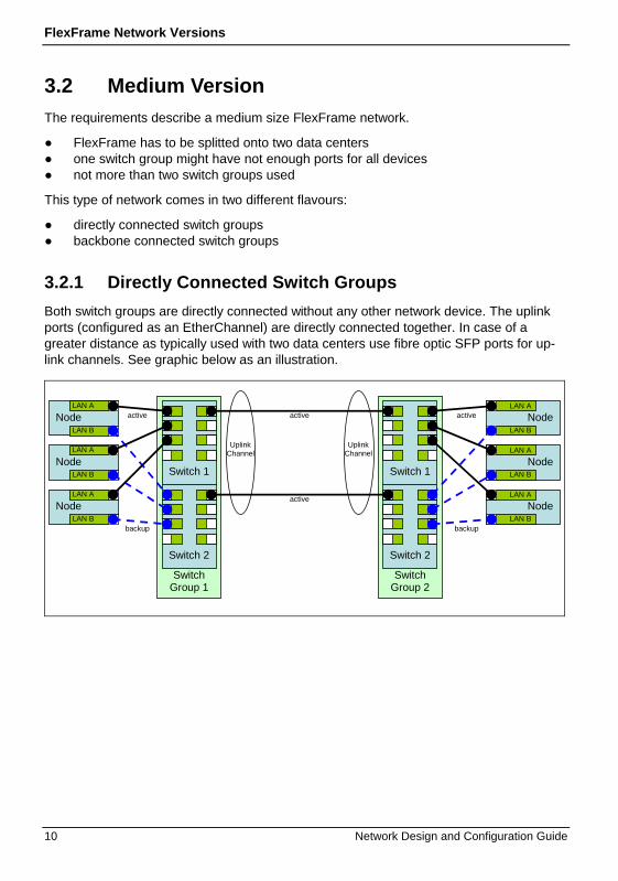
3.2 Medium Version The requirements describe a medium size FlexFrame network.
● FlexFrame has to be splitted onto two data centers ● one switch group might have not enough ports for all devices ● not more than two switch groups used
This type of network comes in two different flavours:
● directly connected switch groups ● backbone connected switch groups
3.2.1 Directly Connected Switch Groups Both switch groups are directly connected without any other network device. The uplink ports (configured as an EtherChannel) are directly connected together. In case of a greater distance as typically used with two data centers use fibre optic SFP ports for up-link channels. See graphic below as an illustration.
Uplink Channel
Uplink Channel
Switch 2
Switch 1
Switch Group 2
LAN A
LAN B Node
Switch 2
Switch 1
Switch Group 1
active
LAN A
LAN B Node
backup
active
backup
LAN A
LAN B Node
LAN A
LAN B Node
LAN A
LAN B Node
LAN A
LAN B Node
active
active

FlexFrame Network Versions
Network Design and Configuration Guide 11
3.2.2 Backbone Connected Switch Groups If a backbone exists between data centers it is more convenient to connect the Flex-Frame switch groups to existing core switches.
Each FlexFrame switch group is connected with its uplink ports to core switch ports. The switch groups may be connected to different core switches. In either case the core switch(es) have to have:
● a static aggregate of ports for each switch group ● carry all VLANs used within FlexFrame aggregates at switch groups without blocking
Node
Node
Node
Node
Node
Node
Node FlexFrame Switch
Group 1
Customer own Core
Switch
Uplink Channel
FlexFrame Switch
Group 2
Customer own Core
Switch
Uplink Channel
Customer Corporate LAN
The core switches are not part of FlexFrame. Neither of automated configuration nor sup-port. Configuration changes at core switches have to be done manually. There are no messages or instructions on changes as FlexFrame does not know about intermediary backbone. The illustration below shows this version.Best practice is a rolling upgrade - step by step.
3.3 Enterprise Version This type of configuration describes the (X)L type of setup.
Use this network version if
● FlexFrame has to be splitted onto two ore more data centers ● two switch groups have not enough ports for all devices ● two or more switch groups have to be used
If more than two switch groups are used they can not be interconnected directly. They have to be connected through (core) switches outside of FlexFrame. These are typically

FlexFrame Network Versions
12 Network Design and Configuration Guide
the core switches of an enterprise network. Much like with the second medium version the core switches have to have:
● a static aggregate of ports for each switch group ● carry all VLANs used within FlexFrame aggregates at switch groups without blocking
The core switches are not part of FlexFrame. Neither of automated configuration nor support. Configuration changes at core switches have to be done manually. There are no messages or instructions on changes as FlexFrame does not know about intermediary backbone. The illustration below shows this version.
Customer own Core
Switch Customer own Core
Switch Customer Corporate LAN
Node
Node
Node
Node
Node
Node
Node
FlexFrame Switch
Group 2
Uplink Channel
FlexFrame Switch
Group 3
FlexFrame Switch
Group 1
Node
Node
Uplink Channel Uplink Channel
FlexFrame Switch Group
FlexFrame Switch Group
Uplink Channel
Uplink Channel
As an extension to the enterprise version shared systems like Control Nodes and NAS systems may be connected directly to core switches. On a project specific solution Pro-fessional Service is able to change FlexFrame configuration to release the formerly used switch group ports. Doing this the administration tools like ff_pool_adm.pl and ff_nas_adm.pl will recognize the direct connection of shared systems to the core switches. Automated switch port configuration for these devices will no longer be per-formed, but hints to configuration changes at core switches will be displayed.

Network Design and Configuration Guide 13
4 Node Configuration
4.1 Linux Bonding Interface SLES-8 does not come with native support for bonding interfaces. To meet this require-ment scripts were added to configure bonding at system boot as needed for FlexFrame 3.1 and 3.2.
As of SLES9 Novell do provide own scripts to configure bonding interfaces. Unfortunately the configuration differs between the SLES (9,10) and the FSC SLES-8 extension.
SLES-9 and SLES-10 allows for the configuration of bonding through commands or via configuration files in /etc/sysconfig/network/ifcfg-bond# and /etc/sysconfig/network/ifcfg-eth#. In both cases substitute IP addresses and interfaces to match your needs.
See configuration file samples below how to configure bonding.
/etc/sysconfig/network/ifcfg-bond0:
BOOTPROTO=static IPADDR=192.168.20.1 NETMASK=255.255.255.0 NETWORK=192.168.20.0 BROADCAST=192.168.20.255 STARTMODE=onboot BONDING_MASTER=yes BONDING_SLAVE_0=eth1 BONDING_SLAVE_1=eth2 BONDING_MODULE_OPTS="miimon=100 mode=1"
And associated /etc/sysconfig/network/ifcfg-eth1 and /etc/sysconfig/network/ifcfg-eth2 files (both are the same):
BOOTPROTO=none STARTMODE=off
The commands to use in order to create a bonding interface like those configured automatically through the configuration above are:
# /sbin/ifconfig bond0 192.168.20.1 netmask 255.255.255.0 broadcast 192.168.20.255 up # /sbin/ifenslave bond0 eth1 # /sbin/ifenslave bond0 eth2
On SLES-8 these commands are the same.

Node Configuration
14 Network Design and Configuration Guide
4.2 Linux VLAN Interface VLAN configuration on SLES-8 to SLES-10 is well supported. As with all other network interfaces VLAN configuration files are named as
/etc/sysconfig/network/ifcfg-vlan#
where # is a number between 1 an 4094 used as VLAN ID. Each VLAN ID requires it’s own configuration file.
For a sample of a VLAN configuration file see below.
/etc/sysconfig/network/ifcfg-vlan10:
ETHERDEVICE='bond0' STARTMODE='onboot' BOOTPROTO='static' IPADDR=192.168.200.11 NETMASK=255.255.255.0 NETWORK='192.168.200.0' BROADCAST=192.168.200.255 WIRELESS='no'
4.3 Solaris IP Multipathing and VLAN Configuration
Unlike with the Linux bonding and VLAN configuration the configuration of VLAN and multipathing is done with a single step as the NIC names of Solaris already include the VLAN configuration. As noted in section Virtual LAN on page 7 the VLAN interface num-ber is calculated of :
1000 * <VLAN ID> + physical interface number
The IPMP bonded and vlan’d network interfaces may be defined in two different ways. Both samples assume correct /etc/hosts and /etc/network entries and boot from local disks. Both samples are using VLAN ID 10 and bonding group storage at physical inter-faces fjgi0 and fjgi2.
The first is the usage of native Solaris configuration files. They may look like sample be-low:
# cat /etc/hostname.fjgi10000 gw1-stt1 deprecated -failover netmask + group storage up addif gw1-st netmask + broadcast + up # cat /etc/hostname.fjgi10002 gw1-stt2 deprecated -failover netmask + group storage up

Node Configuration
Network Design and Configuration Guide 15
The second way is using explicit commands to configure the IPMP bonding:
# /sbin/ifconfig fjgi10000 plumb group storage # /sbin/ifconfig fjgi10000 gw1-stt1 netmask + broadcast + -failover deprecated up # /sbin/ifconfig fjgi10002 plumb group storage # /sbin/ifconfig fjgi10002 gw1-stt2 netmask + broadcast + -failover deprecated up # /sbin/ifconfig fjgi10000 addif gw1-st netmask + failover up
In both cases the result is the same. A redundant network path to VLAN ID 10 using tagged Ethernet frames. For untagged access use native interface numbers (without VLAN ID).
4.4 NetApp Filer Configuration The Filer has to be configured manually via serial cable or if other running network con-nections exist via these. This sample describes only the configuration of the vif and vlan interfaces. To configure the network interfaces use sample below. Replace vif trunk name, IP addresses, netmasks, vlan ids and interfaces with your data (storage is the name of the trunking vif as used with FlexFrame):
filer> vif create single storage e3 e4 filer> vlan create storage 11 14 filer> ifconfig storage-11 192.168.100.203 netmask 255.255.255.0 broadcast 192.168.100.255 mtusize 1500 -wins up filer> ifconfig storage-14 192.168.101.203 netmask 255.255.255.0 broadcast 192.168.101.255 mtusize 1500 -wins up
To make configuration persistent you have to edit /vol/vol0/etc/rc and add above lines.
4.5 EMC Celerra Configuration The Celerra consists of one or two (for redundancy) ControlStations and one or more data movers. The data movers are configured via the ControlStation. Configuration is done via programs prefixed with server_. Each program needs as first argument the configuration destination, the data mover. The data movers are named server_<ID> where ID starts with 2 and counts up.
The sample assumes the first data mover (server_2) with device naming ‘storage’ (as used with FlexFrame) and VLAN ID 10. Change data mover id, IP address, network, broadcast and VLAN ID to mach your needs. The Celerra ControlStation can be con-nected via ssh.

Node Configuration
16 Network Design and Configuration Guide
Sample to configure a tagged EtherChannel interface:
[nasadmin@celerra nas]> /nas/bin/server_ifconfig server_2 –create –Device storage –name storage-10 –protocol IP 192.168.100.17 255.255.255.0 192.168.100.255 [nasadmin@celerra nas]> /nas/bin/server_ifconfig server_2 storage-10 vlan=10 [nasadmin@celerra nas]> /nas/bin/server_ifconfig server_2 storage-10 up

Network Design and Configuration Guide 17
5 Network Switch (of Switch Group) Configuration
The network switches have to be configured for each port with the allowed VLANs, the native/default VLAN and other options.
In normal cases the FlexFrame command ff_swport_adm.pl (see man page or Admin-Guide for detailed description) should be used to configure a switch port according to your needs. To get a better understanding of how the switch gets configured for different devices see table below with some configuration samples depending on Catalyst 3750 family switch:
Cisco Catalyst 3750 Family Configuration
Basic configuration service password-encryption
enable password secret
clock timezone CET 1
clock summer-time cet recurring last Sun Mar 2:00 last Sun Oct 3:00
vtp mode transparent
udld aggressive
no ip http server
snmp-server community public RO
VLAN configuration vlan 10 name storage
Trunked node port configuration (as used with other switches, NASes, multi VLAN nodes, …)
interface GigabitEthernet1/0/1 description trunking node switchport trunk encapsulation dot1q switchport trunk native vlan 10 switchport trunk allowed vlan 10-16 switchport mode trunk no ip address mdix auto flowcontrol receive desired no shutdown spanning-tree portfast trunk

Network Switch (of Switch Group) Configuration
18 Network Design and Configuration Guide
Cisco Catalyst 3750 Family Configuration
Single VLAN node port configu-ration (as used with devices without VLAN configuration)
interface GigabitEthernet1/0/4 description access node switchport access vlan 11 switchport mode access no ip address mdix auto flowcontrol receive desired no shutdown spanning-tree portfast
Static (EtherChannel or Port-Channel) aggregated redundant node port configuration
interface Port-Channel 4 description aggregated node switchport trunk encapsulation dot1q switchport trunk native vlan 10 switchport trunk allowed vlan 10-16 switchport mode trunk
interface GigabitEthernet1/0/10 description aggregated node nic 1 switchport trunk encapsulation dot1q switchport mode trunk no ip address mdix auto no shutdown channel-group 4 mode on spanning-tree portfast trunk
interface GigabitEthernet2/0/10 description aggregated node nic 2 switchport trunk encapsulation dot1q switchport mode trunk no ip address mdix auto no shutdown channel-group 4 mode on spanning-tree portfast trunk
Save configuration copy running-config startup-config
For details see the “Catalyst 3750 Switch Software Configuration Guide” at http://www.cisco.com.

Network Design and Configuration Guide 19
6 Planning Tool
6.1 Client-LAN-to-Corporate-LAN Settings The SwitchGroups form contains three choice fields. They influence the configuration of switch ports for the connection of FlexFrame pool client VLANs to Corporate LAN (where the sapgui’s live) called Client-LAN-to-Corporate-LAN.
In any case two ports are configured for Client-LAN-to-Corporate-LAN (CCLAN) transi-tion. The configuration of CCLAN ports defaults to:
● use only switch group 1 ● use TX ports ● use only one port pair for all Client-LAN VLANs (called trunk). All VLANs are tagged
6.1.1 Choice “Distribute corporate LAN ports to different switch groups”
The activated choice (‘X’) will spread the CCLAN ports onto different switch groups. One port at switch group 1 and one port at switch group 2. If there is only one switch group this choice has no effect and the ports remain both at switch group 1 but on different switches.
6.1.2 Choice “Use Fibre Optic port to corporate LAN” If the switch group has SFP ports at member switches these would be used for CCLAN instead of TX ports. If not the program ff_wiring.pl displays a warning at installation and uses TX ports instead.
6.1.3 Choice “Separate VLANs to corporate LAN” Each Client-LAN gets its own CCLAN port pair. The port configuration uses an untagged VLAN.
6.2 Field for Uplink Channel Port Count The selection field named Port count of switch group interconnects allows to pick a number between 2 and 8. It defines the number of ports used to aggregate the up-link channel to connect another switch group or a core switch. The Cisco EtherChannel protocol is used as static link aggregate for uplinks.


Network Design and Configuration Guide 21
7 Abbreviations ABAP Advanced Business Application Programming
ACC Adaptive Computing Controller
ACI Adaptive Computing Infrastructure
ACPI Advanced Configuration and Power Interface
APM Advanced Power Management
APOLC Advanced Planner & Optimizer Life Cache
CCU Console Connection Unit
CIFS Common Internet File System
DART Data Access in Real Time
DHCP Dynamic Host Configuration Protocol
DIT Domain Information Tree
ERP Enterprise Resource Planning
ESF Enhanced System Facility
EULA End User License Agreement
FAA FlexFrame Autonomous Agent
FC Fiber Channel
FTP File Transfer Protocol
IP Internet Protocol
IPMP IP Multipathing
LAN Local Area Network
LDAP Lightweight Directory Access Protocol
LUN Logical Unit Number
MAC Media Access Control
MINRA Minimal Read Ahead
NAS Network Attached Storage
NDMP Network Data Management Protocol
NFS Network File System

Abbreviations
22 Network Design and Configuration Guide
NIC Network Interface Card
NVRAM Non-Volatile Random Access Memory
OBP Open Boot Prom
OLTP On-Line Transaction Processing
ONTAP Open Network Technology for Appliance Products
OSS Open Source Software
POST Power-On Self Test
PCL PRIMECLUSTER
PFS Production File System (on Celerra)
PW PRIMEPOWER
PXE Preboot Execution Environment
PY PRIMERGY
QA Quality Assurance
QS Quality of Service
RAID Redundant Array of Independent (or Inexpensive) Disks
RARP Reverse Address Resolution Protocol
RDBMS Relational Database Management System
RHEL Red Hat Enterprise Linux
RSB Remote Service Board
SCS System Console Software
SAP BW SAP Business Warehouse
SAPGUI SAP Graphical User Interface
SAPOSS SAP Online System Service
SID System Identifier
SLD System Landscape Directory
SLES SUSE Linux Enterprise Server
SMB Server Message Block
SMC System Management Console
SNMP Simple Network Management Protocol

Abbreviations
Network Design and Configuration Guide 23
SPOC Single Point Of Control
TELNET Telecommunications Network
TFTP Trivial File Transfer Protocol
UDP User Datagram Protocol
UPS Uninterruptible Power Supply
VLAN Virtual Local Area Network
VTOC Virtual Table Of Contents
WAN Wide Area Network
WAS Web Application Server
WAFL Write Anywhere File Layout
XSCF Extended System Control Facility


Network Design and Configuration Guide 25
8 Glossary Adaptive Computing Controller
SAP system for monitoring and controlling SAP environments.
Advanced Business Application Programming Proprietary programming language of SAP.
Advanced Power Management Advanced Power Management defines a layer between the hardware and the operat-ing system that effectively shields the programmer from hardware details.
Application Agent A software program for monitoring and managing applications.
Application Node A host for applications (e.g. SAP instances db, ci, agate, wgate, app etc.). This definition includes Application Servers as well as Database Servers.
Automounter The automounter is an NFS utility that automatically mounts directories on an NFS client as they are needed, and unmounts them when they are no longer needed.
Autonomous Agent Central system management and high availability software component of FlexFrame.
Blade A special form factor for computer nodes.
BladeRunner The working title for the solution part of SAP for FlexFrame.
BOOTPARAM Boot time parameters of the kernel.
BRBACKUP SAP backup and restore tools.
Celerra NAS system of EMC.
Checkpoint Restore On EMC Celerra a SnapSure feature that restores a PFS to a point in time using checkpoint information. As a precaution, SnapSure automatically creates a new checkpoint of the PFS before it performs the restore operation.
Client LAN Virtual network segment within FlexFrame, used for client-server traffic.

Glossary
26 Network Design and Configuration Guide
Common Internet File System A protocol for the sharing of file systems (same as SMB).
Computing Node From the SAP ACI perspective: A host that is used for applications.
Control Agent A software program for monitoring and managing nodes within FlexFrame.
Control LAN Virtual network segment within FlexFrame, used for system management traffic.
Control Node A physical computer system, controlling and monitoring the entire FlexFrame land-scape and running shared services in the rack (dhcp, tftp, ldap etc.).
Control Station A Control Node in an SAP ACI environment.
DART Operating system of Celerra data movers (Data Access in Real Time).
Dynamic Host Configuration Protocol DHCP is a protocol for assigning dynamic IP addresses to devices on a network.
Dynamic Host Configuration Protocol server A DHCP server provides configuration parameters specific to the DHCP client host, required by the host to participate on the Internet.
EMC NAS Network attached storage for file systems of EMC.
Enterprise Resource Planning Enterprise Resource Planning systems are management information systems that in-tegrate and automate many of the business practices associated with the operations or production aspects of a company.
Ethernet
A Local Area Network which supports data transfer rates of 10 megabits per second.
Fiber Channel Fiber Channel is a serial computer bus intended for connecting high-speed storage devices to computers.
Filer Network attached storage for file systems of NetApp.
FlexFrame A joint project in which the main partners are SAP, Network Appliance, Intel and Fu-jitsu Siemens Computers.

Glossary
Network Design and Configuration Guide 27
FlexFrameTM for SAP® FlexFrameTM for SAP® is a radically new architecture for SAP environments. It ex-ploits the latest business-critical computing technology to deliver major cost savings for SAP customers.
FlexFrame internal LAN Switch Cisco network switches which are integral part of the FlexFrame for SAP hardware configuration and which are automatically configured by the FlexFrame for SAP soft-ware.
Gigabit Ethernet A Local Area Network which supports data transfer rates of 1 gigabit (1,000 mega-bits) per second.
Host name The name of a node (assigned to an interface) that is resolved to a unique IP ad-dress. One node can have multiple host names (cf. node name). In SAP environments host names are currently limited to 13 alphanumeric characters including the hyphen (“ - “). The first character must be a letter. In the SAP environ-ment host names are case-sensitive.
Image In the FlexFrame documentation, “Image” is used as a synonym for “Hard Disk Im-age”.
Internet Protocol Address A unique number used by computers to refer to each other when sending information through networks using the Internet Protocol.
Lightweight Directory Access Protocol Protocol for accessing on-line directory services.
Local Area Network A computer network that spans a relatively small area. Most LANs are confined to a single building or group of buildings. However, one LAN can be connected to other LANs over any distance via telephone lines and radio waves. A system of LANs con-nected in this way is called a Wide Area Network (WAN).
Local host name The name of the node (physical computer); it can be displayed and set using the command /bin/hostname.
Logical Unit Number An address for a single (SCSI) disk drive.
MAC address Device identifier number of a Network Interface Card. In full: "media access control address".

Glossary
28 Network Design and Configuration Guide
MaxDB A relational database system from mySQL (formerly ADABAS and SAPDB).
Media Access Control address An identifier for network devices, usually unique. The MAC address is stored physi-cally on the device.
NAS system Network Attached Storage of any vendor (in our context: EMC NAS or NetApp Filer).
NDMPcopy NDMPcopy transfers data between Filers using the Network Data Management Pro-tocol (NDMP).
Netboot A boot procedure for computers where the operating system is provided via a net-work instead of local disks.
Netweaver
SAP NetWeaver is the technical foundation of SAP solutions.
Network Appliance Filer See “Filer”.
Network Attached Storage A data storage device that is connected via a network to one or multiple computers.
Network File System A network protocol for network-based storage access.
Network Interface Card A hardware device that allows computer communication via networks.
Node A physical computer system controlled by an OS.
Node name The name of a physical node as returned by the command uname -n. Each node name within a FlexFrame environment must be unique.
Non-Volatile Random Access Memory A type of memory that retains its contents when the power is turned off.
On-Line Transaction Processing Transaction processing via computer networks.
OpenLDAP An Open Source LDAP Service Implementation.
Open Network Technology for Appliance Products The operating system of Network Appliance Filers.

Glossary
Network Design and Configuration Guide 29
Open Source Software Software that is distributed free of charge under an open source license, such as the GNU Public License.
Oracle RAC A cluster database by Oracle Corporation.
Physical host Name of a physical computer system (node).
Power-On Self Test Part of a computer's boot process; automatic testing of diverse hardware compo-nents.
Preboot Execution Environment An environment that allows a computer to boot from a network resource without hav-ing a local operating system installed.
PRIMECLUSTER Fujitsu Siemens Computer’s high-availability and clustering software.
PRIMEPOWER
Fujitsu Siemens Computer's SPARC-based server product line.
PRIMERGY
Fujitsu Siemens Computer's i386-based server product line.
Red Hat Enterprise Linux Linux distribution by Red Hat, Inc., targeting business customers.
Reverse Address Resolution Protocol A protocol allowing resolution of an IP address corresponding to a MAC address.
SAP Service In FlexFrame: SAP Service and DB Services.
SAP service script An administration script for starting and stopping an SAP application on a virtual host.
SAP Solution Manager Service portal for the implementation, operation and optimization of an SAP solution.
SAPLogon Front-end software for SAPGUI.
SAPRouter Router for SAP services like SAPGUI or SAPTELNET.
SavVol A Celerra volume to which SnapSure copies original point-in-time data blocks from the PFS before the blocks are altered by a PFS transaction.

Glossary
30 Network Design and Configuration Guide
Server A physical host (hardware), same as node.
Service A software program providing functions to clients.
Service type The type of an application or service (db, ci, app, agate, wgate etc.).
Single Point of Control In FlexFrame: One user interface to control a whole FlexFrame environment.
Storage LAN A virtual LAN segment within a FlexFrame environment, carrying the traffic to NAS systems.
SUSE Linux Enterprise Server A Linux distribution by Novell, specializing in server installations.
Telecommunications Network A terminal emulation program for TCP/IP networks such as the Internet.
Trivial File Transfer Protocol A simple form of the File Transfer Protocol (FTP). TFTP uses the User Datagram Protocol (UDP) and provides no security features. It is often used by servers to boot diskless workstations, X-terminals, and routers.
TFTP server A simple FTP implementation.
Virtual host The name of the virtual host on which an application runs; it is assigned to a physical node when an application is started.
Virtual Local Area Network A VLAN is a logically segmented network mapped over physical hardware according to the IEEE 802.1q standard.
Virtualization Virtualization means the separation of hardware and processes. In a virtualized envi-ronment (FlexFrame), a process can be moved between hardware nodes while stay-ing transparent to the user and application.

Network Design and Configuration Guide 31
9 Index C
concept and design 3
E
EMC Celerra configuration 15
F
FlexFrame network versions 9
enterprise version 11
medium version 10
small version 9
L
link aggregation 5
Linux 5
Solaris 6
Linux
bonding interface 13
VLAN interface 14
N
NetApp Filer configuration 15
network switch configuration 17
node configuration 13
P
Planning Tool 19
R
related documents 2
S
Solaris
IP multipathing 14
VLAN configuration 14
V
virtual LAN 7

Information on this document On April 1, 2009, Fujitsu became the sole owner of Fujitsu Siemens Compu-ters. This new subsidiary of Fujitsu has been renamed Fujitsu Technology So-lutions.
This document from the document archive refers to a product version which was released a considerable time ago or which is no longer marketed.
Please note that all company references and copyrights in this document have been legally transferred to Fujitsu Technology Solutions.
Contact and support addresses will now be offered by Fujitsu Technology So-lutions and have the format …@ts.fujitsu.com.
The Internet pages of Fujitsu Technology Solutions are available at http://ts.fujitsu.com/... and the user documentation at http://manuals.ts.fujitsu.com.
Copyright Fujitsu Technology Solutions, 2009
Hinweise zum vorliegenden Dokument Zum 1. April 2009 ist Fujitsu Siemens Computers in den alleinigen Besitz von Fujitsu übergegangen. Diese neue Tochtergesellschaft von Fujitsu trägt seit-dem den Namen Fujitsu Technology Solutions.
Das vorliegende Dokument aus dem Dokumentenarchiv bezieht sich auf eine bereits vor längerer Zeit freigegebene oder nicht mehr im Vertrieb befindliche Produktversion.
Bitte beachten Sie, dass alle Firmenbezüge und Copyrights im vorliegenden Dokument rechtlich auf Fujitsu Technology Solutions übergegangen sind.
Kontakt- und Supportadressen werden nun von Fujitsu Technology Solutions angeboten und haben die Form …@ts.fujitsu.com.
Die Internetseiten von Fujitsu Technology Solutions finden Sie unter http://de.ts.fujitsu.com/..., und unter http://manuals.ts.fujitsu.com finden Sie die Benutzerdokumentation.
Copyright Fujitsu Technology Solutions, 2009