Embed Size (px)
Citation preview

FlexFrame™ for SAP®
Version 5.1A
Administration and Operation
Edition July 2012
Document Version 1.2

Fujitsu Limited
© Copyright Fujitsu Technology Solutions 2012
FlexFrame™ and PRIMERGY™ are trademarks or registered trademarks of
Fujitsu Limited in Japan and other countries.
SAP® and NetWeaver™ are trademarks or registered trademarks of SAP AG in
Germany and in several other countries
Linux® is a registered trademark of Linus Torvalds
SUSE® Linux is a registered trademark of Novell, Inc., in the United States and
other countries
Oracle™ and Java™ are trademarks of ORACLE Corporation and/or its affiliates
Intel® and PXE
® are registered trademarks of Intel Corporation in the United States
and other countries
MaxDB® is a registered trademark of MySQL AB, Sweden
MySQL® is a registered trademark of MySQL AB, Sweden
NetApp® and the Network Appliance
® logo are registered trademarks and Network
Appliance™ and Data ONTAP™ are trademarks of NetApp, Inc. in the U.S. and
other countries.
EMC®, CLARiiON
®, Symmetrix
® and Celerra™ are trademarks or registered
trademarks of EMC Corporation in the United States and other countries
VMware®, ESX
®, ESXi, VMware vCenter, VMware vSphere are registered
trademarks or trademarks of VMware, Inc. in the United States and/or other
jurisdictions.
Ethernet® is a registered trademark of XEROX, Inc., Digital Equipment Corporation
and Intel Corporation
Windows® and Word
® are registered trademarks of Microsoft Corporation
All other hardware and software names used are trademarks of their respective
companies.
All rights, including rights of translation, reproduction by printing, copying or similar
methods, in part or in whole, are reserved.
Offenders will be liable for damages.
All rights, including rights created by patent grant or registration of a utility model or
design, are reserved.
Delivery subject to availability. Right of technical modification reserved.


Administration and Operation
Contents
1 Introduction ..................................................................................................... 1 1.1 Requirements .................................................................................................... 1 1.2 Notational Conventions ..................................................................................... 1 1.3 Document History .............................................................................................. 2 1.4 Related Documents ........................................................................................... 2 1.5 Special Hints for FlexFrame 5.1A ...................................................................... 2 1.5.1 Incompatibilities (command scripts) .................................................................. 3
2 FlexFrame Architecture .................................................................................. 5 2.1 General Notes on FlexFrame ............................................................................ 5 2.2 Hardware and Software ..................................................................................... 6 2.3 Shared Operating System ................................................................................. 9 2.3.1 Shared OS Boot Concept .................................................................................. 9 2.3.2 Control Nodes ................................................................................................. 10 2.3.3 Application Nodes ........................................................................................... 10 2.4 FlexFrame Structure in LDAP.......................................................................... 11 2.4.1 Working with LDAP ......................................................................................... 12 2.5 Linux-HA Cluster on Control Center ................................................................ 12 2.5.1 Terminology..................................................................................................... 12 2.5.2 Simple Resources ........................................................................................... 14 2.5.2.1 Constraints ...................................................................................................... 14 2.5.2.2 Score ............................................................................................................... 14 2.5.2.3 Stickiness ........................................................................................................ 15 2.5.2.4 Resource Groups ............................................................................................ 17 2.5.3 FlexFrame Specific Configuration ................................................................... 17 2.5.3.1 Configuration of Limits for Cluster Resources ................................................. 19 2.5.3.2 LDAP Configuration ......................................................................................... 20 2.5.3.3 Ressource ff_manage ..................................................................................... 22 2.5.3.4 Resource Netbooot ......................................................................................... 22 2.5.3.5 STONITH......................................................................................................... 22 2.5.3.6 Configuring the Cluster .................................................................................... 24 2.5.3.7 Starting Behavior of the Cluster ....................................................................... 25 2.5.3.8 Status Information of the Clusters ................................................................... 25 2.5.4 Linux-HA CLI Commands ................................................................................ 26 2.5.5 Linux-HA Logfile .............................................................................................. 27 2.5.6 Linux-HA GUI .................................................................................................. 27 2.6 Network ........................................................................................................... 27 2.6.1 LAN Failover.................................................................................................... 28 2.6.2 Segments ........................................................................................................ 28 2.6.3 Network Switches ............................................................................................ 29 2.6.4 Network Speed ................................................................................................ 30 2.6.5 Network Switch Groups ................................................................................... 30

Contents
Administration and Operation
2.6.6 Network Switch Ports ...................................................................................... 30 2.6.7 Automounter Concept ...................................................................................... 31 2.7 Storage Systems ............................................................................................. 34 2.7.1 NAS Support Architectural Overview ............................................................... 34 2.7.1.1 Network Appliance Filer ................................................................................... 34 2.7.1.2 EMC NAS (Celerra) ......................................................................................... 36 2.7.2 SAN Support Architectural Overview ............................................................... 40 2.7.2.1 SAN Basic Layers ............................................................................................ 41 2.7.2.2 Scope of the FlexFrame SAN Integration ........................................................ 42 2.7.2.3 Rules and Restrictions ..................................................................................... 43
3 FlexFrame Basic Administration .................................................................. 44 3.1 Accessing a FlexFrame Landscape (Remote Administration) ......................... 44 3.2 Powering up the FlexFrame Landscape .......................................................... 44 3.3 Powering off the FlexFrame Landscape .......................................................... 45 3.4 Reactivating ANs after Power Shutdown by FA Agents .................................. 48 3.5 Displaying the Current FlexFrame Configuration State ................................... 49 3.5.1 FlexFrame Web Portal ..................................................................................... 50 3.5.2 FA Autonomous Agents ................................................................................... 51 3.5.2.1 State of Pools .................................................................................................. 51 3.5.2.2 State of Application Nodes .............................................................................. 52 3.5.2.3 State of SAP Systems ..................................................................................... 52 3.5.2.4 State of SID Instances ..................................................................................... 52 3.5.3 Networks.......................................................................................................... 52 3.5.4 ServerView Operations Manager ..................................................................... 53 3.5.5 Cluster Status .................................................................................................. 61 3.5.6 Supported Hardware ....................................................................................... 61 3.5.7 Management Blades ........................................................................................ 61 3.6 FlexFrame Backup with Tape Library .............................................................. 62 3.6.1 NetWorker ....................................................................................................... 62 3.6.2 ARCserve ........................................................................................................ 63
4 Pools and Groups .......................................................................................... 64 4.1 Adding a Pool .................................................................................................. 64 4.2 Removing a Pool ............................................................................................. 69 4.3 Listing Pool Details .......................................................................................... 70 4.4 Listing All Pools ............................................................................................... 74 4.5 Changing Pool DNS Domain ........................................................................... 76 4.6 Changing Pool Default Router ......................................................................... 77 4.7 Adding a Group to a Pool ................................................................................ 77 4.8 Removing Pool Group ..................................................................................... 78 4.9 Changing Group Assignment of Application Nodes ......................................... 79 4.10 Changing Group and Pool Assignment of Application Nodes .......................... 79 4.11 Hosts Database ............................................................................................... 79 4.11.1 Script: ff_hosts.sh ............................................................................................ 80

Contents
Administration and Operation
5 User and Groups Administration ................................................................. 82 5.1 Create, Modify, Delete, or List User(s) for Application Nodes ......................... 82 5.2 Creating, Modifying, Deleting or Listing Group(s) for Application Nodes ......... 84 5.3 Creating, Modifying, Deleting or Listing Service(s) for Application Nodes ....... 87
6 Pool-independent Spare Nodes ................................................................... 89 6.1 Creation of Spare Nodes in the ADMINPOOL ................................................. 89 6.2 Moving of a Spare Node .................................................................................. 89 6.3 Listfunction for Spare Nodes ........................................................................... 90 6.4 Handling Pool-independent Spare Nodes with FA Agents .............................. 90
7 Application Nodes Administration ............................................................... 91 7.1 Listing Application Nodes ................................................................................ 91 7.1.1 Displaying Information on a Specific Application Node ................................... 91 7.1.2 Displaying Information of all Application Nodes............................................... 95 7.2 Adding Application Nodes ............................................................................... 96 7.3 Removing Application Nodes ........................................................................ 101 7.4 Renaming Application Nodes ........................................................................ 101 7.5 Moving Application Nodes between Pools .................................................... 102 7.6 Application Nodes and SAN .......................................................................... 104 7.7 Administrating Blade Server Cabinets ........................................................... 104 7.7.1 Listing Blade Server Cabinets ....................................................................... 105 7.7.1.1 Displaying Information on a Specific Blade Server Cabinet .......................... 105 7.7.1.2 Displaying Information on all Configured Blade Server Cabinets .................. 106 7.7.2 Adding Blade Server Cabinets ...................................................................... 107 7.7.3 Removing Blade Server Cabinets ................................................................. 109 7.7.4 Changing Switch Blade Type ........................................................................ 111 7.7.5 Changing Switch Blade Name ....................................................................... 112 7.7.6 Changing Switch Blade Password ................................................................. 113 7.7.7 Getting Switch Blade Configuration ............................................................... 114 7.7.8 Change Switch Blade Uplink ......................................................................... 115 7.7.9 Move a Blade Cabinet to Another Switch Group ........................................... 116 7.8 Administrating ESX Servers and Virtual Machines ........................................ 118 7.8.1 Getting Started with ESX Servers and VMs .................................................. 118 7.8.2 ESX related global FlexFrame parameters.................................................... 120 7.8.2.1 System Code for ESX Servers and VMs ....................................................... 120 7.8.2.2 vCenter Server .............................................................................................. 121 7.8.2.3 Control LAN Default Router for ESX Servers ................................................ 123 7.8.3 Adding ESX Servers ...................................................................................... 124 7.8.4 Completing ESX Server Configuration .......................................................... 126 7.8.5 Removing ESX Servers ................................................................................. 127 7.8.6 Displaying Information about ESX Servers and VMs .................................... 128 7.8.7 ESX Servers and Pools ................................................................................. 131 7.8.8 Special Functions for Virtual Machines ......................................................... 132 7.8.9 Virtual Machine Properties and ESXi Resources .......................................... 134

Contents
Administration and Operation
7.8.10 Using vSphere Functions for FlexFrame Objects .......................................... 136 7.9 Script for Power on/off/Reboot of a Computing Node in FF4S ...................... 137 7.9.1 Synopsis ........................................................................................................ 137
8 Storage Systems Administration ............................................................... 138 8.1 NAS Systems Configuration (EMC and NetApp) ........................................... 138 8.1.1 Adding a New NAS ........................................................................................ 138 8.1.2 Removing a NAS ........................................................................................... 141 8.1.3 Configuring SNMP Traps for NetApp Filers ................................................... 142 8.1.4 Displaying all configured NAS ....................................................................... 143 8.1.5 Displaying NAS Configuration ....................................................................... 144 8.1.6 Adding a Pool to a NAS ................................................................................. 145 8.1.7 Removing a Pool from a NAS ........................................................................ 146 8.1.8 Adding a Blade (Data Mover) to an EMC Celerra NAS ................................. 147 8.1.9 Removing a Blade (Data Mover) from an EMC Celerra NAS ........................ 148 8.1.10 Create NAS Cluster Partnership .................................................................... 149 8.1.11 Move a NAS to another Switch Group ........................................................... 149 8.1.12 Switching a NetApp Filer between 1Gbit and 10Gbit ..................................... 150 8.1.13 Changing NAS Command Shell .................................................................... 150 8.1.14 Changing NAS LinkAggregate Ports ............................................................. 151 8.1.15 NAS Disk Free ............................................................................................... 152 8.1.16 Celerra SRDF-NAS High Availability ............................................................. 154 8.1.16.1 Syntax............................................................................................................ 154 8.1.16.2 Background Processes .................................................................................. 155 8.1.16.3 Diagnosis ....................................................................................................... 155 8.1.16.4 Return Codes ................................................................................................ 156 8.1.16.5 Used File Ressources ................................................................................... 157 8.2 SAN Configuration in a FlexFrame Environment ........................................... 158 8.2.1 Setting Up the SAN Configuration ................................................................. 158 8.2.1.1 Configuring Storage ....................................................................................... 158 8.2.1.2 General Remark for the Use of Navisphere ................................................... 158 8.2.1.3 Storage System Access................................................................................. 158 8.2.1.4 LUN Creation ................................................................................................. 159 8.2.1.5 Recording LUN Information ........................................................................... 161 8.2.2 Configuring Application Nodes ...................................................................... 162 8.2.3 Connecting the Storage to the Application Nodes ......................................... 163 8.2.3.1 Creating Zones on the Fibre Channel Switches ............................................ 164 8.2.3.2 Checking Visibility of the Storage System on the Application Node .............. 165 8.2.3.3 Registering Host Initiators with a CLARiiON/FibreCAT CX............................ 165 8.2.3.4 Mapping LUNs to the Application Nodes ....................................................... 166 8.2.3.5 Checking Visibility of the LUNs on the Application Node ............................... 168 8.2.4 Creating Volumes and File Systems for a SAP System ................................ 169 8.2.4.1 Creating a Linux LVM2 Volume Group for FlexFrame Usage ........................ 169 8.2.4.2 Completing the Configuration and Testing Usability of SAN for an SID ......... 170 8.3 Dynamic LUN Masking .................................................................................. 172

Contents
Administration and Operation
8.3.1 Using StorMan to Reconfigure SAN .............................................................. 172 8.3.1.1 Installation of SMI-S Provider ........................................................................ 172 8.3.1.2 Installation of StorMan ................................................................................... 174 8.4 SRDF Support in FlexFrame ......................................................................... 179 8.4.1 Storage System Configuration....................................................................... 180 8.4.2 Configuring Application Nodes for SAN SRDF Usage ................................... 180 8.4.3 FlexFrame SAN Configuration for SRDF ....................................................... 184 8.4.4 SAN SRDF Usage in FlexFrame ................................................................... 187 8.5 FlexFrame SAN Configuration ....................................................................... 189 8.5.1 Script: ff_san_ldap_conf.pl ............................................................................ 189 8.5.2 FlexFrame SAN Configuration File ................................................................ 191 8.5.3 SAN Support Scripts ..................................................................................... 198 8.5.3.1 Script: ff_san_mount.sh ................................................................................. 198 8.5.3.2 Script: ff_san_info.sh ..................................................................................... 199 8.5.3.3 Script: ff_qlascan.sh ...................................................................................... 201 8.5.3.4 Script: ff_san_srdf.pl ...................................................................................... 201 8.5.3.5 Script: ff_san_luns.pl ..................................................................................... 204
9 Switch Administration ................................................................................ 208 9.1 Adding a Switch to a Switch Group ............................................................... 208 9.2 Removing a Switch from a Switch Group ...................................................... 211 9.3 Listing a Switch Group Configuration ............................................................ 212 9.4 Generating a Switch Group Configuration ..................................................... 214 9.5 Changing the Password of a Switch Group ................................................... 215 9.6 Changing the Host Name of a Switch Group ................................................. 216 9.7 Displaying/Changing Common Network Configuration Parameters .............. 218 9.8 Adding a Switch Group .................................................................................. 220 9.9 Adding an Expansion Module ........................................................................ 223 9.10 Removing an Expansion Module ................................................................... 224 9.11 Removing a Switch Group ............................................................................. 225 9.12 Adding an Uplink to Switch Group ................................................................. 226 9.13 Extend an Uplink of Switch Group ................................................................. 227 9.14 Delete an Uplink of Switch Group .................................................................. 228 9.15 Migrating Switches of a Switch Group ........................................................... 230 9.16 Adding a Switch Port Configuration ............................................................... 233 9.17 Removing a Switch Port Configuration .......................................................... 235 9.18 Displaying a Switch Port Configuration ......................................................... 236 9.19 Displaying the Complete Switch Port Configuration ...................................... 237 9.20 Moving Device Connection to Core Switch.................................................... 239 9.20.1 Move Control Center to Core Switch ............................................................. 239 9.20.2 Move Client LAN to Core Switch ................................................................... 240 9.20.3 Move NAS System to Core Switch ................................................................ 240 9.20.4 Move Application Node to Core Switch ......................................................... 241 9.20.5 Move ESX Server to Core Switch .................................................................. 242 9.20.6 Move BX Cabinet to Core Switch .................................................................. 242

Contents
Administration and Operation
10 SAP System Handling ................................................................................. 244 10.1 Listing SAP SIDs and Instances .................................................................... 245 10.2 Updating System Configuration Files ............................................................ 247 10.3 Adding/Removing/Modifying SAP SIDs and Instances (Classic SAP Services)247 10.4 Removing SAP SIDs and Instances .............................................................. 253 10.5 Adding/Removing SAP SIDs (addon services) .............................................. 254 10.5.1 BOBJ – Business Objects.............................................................................. 254 10.5.2 Content Server (CMS) ................................................................................... 255 10.5.3 MDM – Master Data Management ................................................................. 259 10.5.4 SMD – Solution Manager Diagnostics ........................................................... 263 10.5.5 TREX (Search and Classification Service) .................................................... 265 10.6 Cloning a SAP SID into a Different Pool ........................................................ 268 10.6.1 Script: ff_clone_sid.pl .................................................................................... 268 10.6.2 Changing User and Group IDs after Cloning ................................................. 269 10.7 Cloning a SAP system into a different Pool ................................................... 269 10.7.1 Script: ff_clone_sap.sh .................................................................................. 269 10.7.1.1 Cloning SAP systems with MaxDB ................................................................ 273 10.7.1.2 Post cloning steps – DB2............................................................................... 274 10.7.1.3 Post cloning steps – Oracle ........................................................................... 274 10.7.1.4 Post cloning steps – MaxDB .......................................................................... 274 10.7.1.5 Cloning a SAP system – example session .................................................... 275 10.8 Relocating sapdata/saplog by ff_sid_mnt_adm.pl ......................................... 276 10.9 Multiple NAS Systems and Multiple Volumes ................................................ 279 10.9.1 NetApp Filer ................................................................................................... 280 10.9.2 EMC Celerra .................................................................................................. 281 10.10 Upgrading a SAP System .............................................................................. 282 10.10.1 Service Port ................................................................................................... 282 10.10.2 FA Agents ...................................................................................................... 283 10.10.3 Support SAP Upgrade ................................................................................... 284 10.11 SAP Kernel Updates and Patches ................................................................. 286 10.12 Unloading volFF ............................................................................................ 287 10.12.1 Status Quo/Solution ....................................................................................... 287 10.12.2 ff_relocate_sid_data.pl .................................................................................. 287 10.12.3 LDAP ............................................................................................................. 291 10.12.4 Move Data from volFF (how to) ..................................................................... 293 10.12.4.1 Specify Volume Before Installing SAP ........................................................... 293 10.12.4.2 Moving an Existing /usr/sap/SID .................................................................... 294 10.12.5 Delete Entries from LDAP.............................................................................. 294 10.13 Administrating SAP Services ......................................................................... 295 10.13.1 Displaying Status of SAP Services ................................................................ 295 10.13.1.1 myAMC.FA WebGUI ..................................................................................... 295 10.13.1.2 List SAP Services .......................................................................................... 296 10.13.2 Starting and Stopping Application Services ................................................... 297 10.13.2.1 Starting and Stopping SAP Services Without Root Privileges ....................... 298 10.13.2.2 SAP Service Scripts ...................................................................................... 299

Contents
Administration and Operation
10.13.2.3 SAP Service Script Actions ........................................................................... 300 10.13.2.4 SAP Service Script logging............................................................................ 303 10.13.2.5 SAP Service Script User Exits ....................................................................... 303 10.13.3 Return Code of the SAP Service Script ......................................................... 304 10.13.4 Starting and Stopping Multiple SAP Services ................................................ 304 10.13.5 Removing an Application from Monitoring by FA Agents .............................. 305 10.13.5.1 Stopping and Starting an Application for Upgrades Using r3up.................... 307 10.13.6 Service Switchover ........................................................................................ 307 10.13.7 Use ServicePings from FA Agents ................................................................ 309
11 Software and Hardware Update and Maintenance ................................... 311 11.1 Upgrading the Entire FlexFrame Landscape ................................................. 311 11.2 Software Upgrade on the Control Node ........................................................ 311 11.2.1 FlexFrame Control Node Software ................................................................ 313 11.2.2 Updating/Installing a New Linux Kernel ......................................................... 313 11.2.2.1 Software Stage .............................................................................................. 313 11.2.2.2 Install the New Kernel ................................................................................... 314 11.2.2.3 Reboot the Control Node ............................................................................... 314 11.2.3 Backup/Restore of FlexFrame Control Nodes ............................................... 315 11.2.3.1 Backup of a Control Node ............................................................................. 315 11.2.3.2 Restore of a Control Node ............................................................................. 315 11.3 Maintenance of the Control Node - Hardware ............................................... 317 11.3.1 Exchanging a Control Node........................................................................... 317 11.3.1.1 Hardware Failed, Hard Disk and Installed OS are not Affected ..................... 317 11.3.1.2 One Hard Disk is Defect, the Other One is Undamaged ............................... 318 11.3.1.3 The Control Nodes OS is Damaged .............................................................. 318 11.3.2 Replacing a Network Card – Control Node ................................................... 318 11.4 Maintenance of Application Nodes - Software ............................................... 318 11.4.1 Introduction.................................................................................................... 318 11.4.2 Schematic Overview ...................................................................................... 319 11.4.3 Installing Application Node Images from Installation Media .......................... 321 11.4.3.1 Installing the Application Node Image ........................................................... 321 11.4.3.2 Understanding the Application Node Image .................................................. 323 11.4.4 Step #1: Creating a Maintenance Base Image .............................................. 323 11.4.5 Step #2: Assigning the Maintenance Image, booting and maintaining .......... 325 11.4.5.1 Choosing a Node ........................................................................................... 326 11.4.5.2 Assigning ....................................................................................................... 327 11.4.5.3 Booting .......................................................................................................... 328 11.4.5.4 Maintaining .................................................................................................... 329 11.4.6 Step #3: Reverting the Maintenance Image .................................................. 330 11.4.7 Migrating remaining Application Nodes ......................................................... 333 11.4.8 Re-Using the Maintenance Image ................................................................. 335 11.4.9 Maintaining Use Cases ................................................................................. 337 11.4.9.1 Service Packs ................................................................................................ 338 11.4.9.2 Updating/Installing a New Linux Kernel ......................................................... 338

Contents
Administration and Operation
11.4.9.3 ServerView Update ........................................................................................ 340 11.4.9.4 Upgrading the Application Software .............................................................. 341 11.4.9.5 Updating RPM Packages on an Application Node ......................................... 342 11.4.9.6 Updating vmware-open-vm-tools ................................................................... 343 11.4.9.7 Upgrading the Application Software .............................................................. 344 11.4.9.8 Updating RPM Packages on an Application Node ......................................... 345 11.4.9.6 Updating vmware-tools .................................................................................. 346 11.5 Maintenance of the Application Nodes - Hardware ........................................ 347 11.5.1 Changing BIOS Settings for Netboot ............................................................. 347 11.5.2 Replacing a Network Card – Application Node .............................................. 347 11.5.3 Replacing a Switch Blade .............................................................................. 349 11.5.4 Replacing Power Control Hardware .............................................................. 349 11.6 Maintenance of ESXi Servers ........................................................................ 350 11.6.1 BIOS Updates ................................................................................................ 350 11.6.2 Replacing a Network Card - ESXi Server ...................................................... 350 11.6.3 ESXi Updates and Patches ........................................................................... 350 11.7 Maintenance of Other FlexFrame Components ............................................. 351 11.7.1 NetApp Storage ............................................................................................. 351 11.7.2 EMC Storage ................................................................................................. 351 11.7.3 Cisco Switches and Switch Blades ................................................................ 352 11.7.3.1 Firmware Update ........................................................................................... 352 11.7.3.2 Backup of Switch Configurations ................................................................... 352 11.7.3.3 Restore of Switch Configurations .................................................................. 353 11.7.4 DNS Servers .................................................................................................. 354 11.7.5 Third Party Products ...................................................................................... 354 11.8 MyAMC Agents .............................................................................................. 355 11.9 Project specific changes ................................................................................ 355 11.9.1 The ff_projectinfo.sh command ..................................................................... 355
12 Troubleshooting .......................................................................................... 359 12.1 Locking of Flex Frame Administration Commands ........................................ 359 12.2 Script Logging in FlexFrame .......................................................................... 360 12.3 Log Files ........................................................................................................ 362 12.4 Network Errors ............................................................................................... 363 12.5 NFS Mount Messages ................................................................................... 363 12.6 LDAP Error Codes and Messages ................................................................. 363 12.7 LDAP and Cache Coherence ........................................................................ 365 12.7.1 Linux .............................................................................................................. 365 12.8 Start/Stop Script Errors .................................................................................. 365 12.8.1 Severity ‗INFO‘ .............................................................................................. 366 12.8.2 Severity ‗WARN‘ ............................................................................................ 366 12.8.3 Severity ‗ERROR‘ .......................................................................................... 366 12.8.4 Severity ‚DEBUG‗ .......................................................................................... 366 12.9 Script Debugging ........................................................................................... 366 12.9.1 Shell Scripts ................................................................................................... 366

Contents
Administration and Operation
12.9.2 Perl Scripts .................................................................................................... 367 12.10 Debugging the Linux Kernel .......................................................................... 367 12.10.1 Netconsole .................................................................................................... 367 12.10.2 Capturing Crash Dumps ................................................................................ 368 12.10.2.1 Common Restrictions for Taking Crash Dumps ............................................ 368 12.10.2.2 „Kdump― Kernel Crash Dump Capturing ........................................................ 368 12.10.2.3 Forcing a Crash Dump .................................................................................. 369 12.11 Activate core dumps on CN or AN ................................................................. 369
13 Abbreviations .............................................................................................. 371
14 Glossary ....................................................................................................... 375
15 Index ............................................................................................................. 381


Administration and Operation 1
1 Introduction
This document provides instructions on administrating and operating an installed
FlexFrame™ 5.1A environment. It focuses on general aspects of the architecture as well
as on software updates, hardware extensions and FlexFrame-specific configuration.
It does not cover the installation of an entire FlexFrame environment. Please refer to the
―Installation of a FlexFrame Environment‖ manual for information on initial installation.
1.1 Requirements
This document addresses administrators on FlexFrame environments. We assume that
the reader of this document has technical background knowledge in the areas of
operating systems (Linux®), IP networking and SAP
® basis.
1.2 Notational Conventions
The following conventions are used in this manual:
Additional information that should be observed.
Warning that must be observed.
fixed font Names of paths, files, commands, and system output.
<fixed font> Names of variables.
fixed font User input in command examples (if applicable using <> with variables).
Command prompt: # The notation
control1:/<somewhere> # <command>
indicates that the command <command> is issued on the first
Control Node in the directory /<somewhere>.
The reader may need to change into the directory first, e.g.
control1:~ # cd /<somewhere>
control1:/<somewhere># <command>.

Introduction Document History
2 Administration and Operation
1.3 Document History
Document
Version
Changes Date
1.0 First Edition 2011-11-23
1.1 Support Nexus 5548, 5596
Support Catalyst 3750X
Support BOBJ 4.0 (SBOP)
New hint in Chapter 7.8.9 ―Virtual Machine
Properties and ESXi Resources‖
2012-05-04
1.2 Update of chapter 3.3 ―Powering off the FlexFrame
Landscape‖
2012-07-04
1.4 Related Documents
FlexFrame™ for SAP® – Administration and Operation
FlexFrame™ for SAP® – HW Characteristics Quickguides
FlexFrame™ for SAP
® – Installation ACC 7.3
FlexFrame™ for SAP® – Installation Guide for SAP Solutions
FlexFrame™ for SAP® – Installation of a FlexFrame Environment
FlexFrame™ for SAP® – Management Tool
FlexFrame™ for SAP
® – myAMC.FA_Agents Installation and Administration
FlexFrame™ for SAP
® – myAMC.FA_Messenger Installation and Administration
FlexFrame™ for SAP
® – myAMC.FA_LogAgent Installation and Administration
FlexFrame™ for SAP® – Network Design and Configuration Guide
FlexFrame™ for SAP® – Security Guide
FlexFrame™ for SAP® – Technical White Paper
FlexFrame™ for SAP® – Upgrading FlexFrame 4.2B or 5.0A to 5.1A
ServerView Documentation
SUSE Linux Enterprise Server Documentation
1.5 Special Hints for FlexFrame 5.1A
In this document, you often will find console output, configuration data and installation
examples which are based on earlier FlexFrame versions. Please keep in mind that these
are examples and may look slightly different on the new operating systems introduced in
FlexFrame 5.1A.
The two Control Nodes (CN) of FlexFrame for SAP are also named as the FlexFrame
Control Center (CC). In this documentation the notation Control Node (CN) is used as a
synonym for Control Center (CC) and the other way round.

Special Hints for FlexFrame 5.1A Introduction
Administration and Operation 3
1.5.1 Incompatibilities (command scripts)
There are some changes with supplied scripts
The script ff_change_id.pl is not further available.
With the script ff_user_adm.pl resp. ff_group_adm.pl you can change UIDs
or GIDs of a specific user/group
The command line syntax of ff_setup_sid_folder.sh changed to
ff_setup_sid_folder.sh –s <SID> -p <pool>
With script f f _nas_adm. pl , the operation mode conf 10gb is no longer supported.
Use operation mode move instead.


Administration and Operation 5
2 FlexFrame Architecture
The FlexFrame solution is a revolutionary approach to run complex SAP solutions with
higher efficiency. At the same time some major changes of the configuration paradigms
for infrastructures have been implemented. These changes are:
A shared operating system booted via IP networks for the SAP Application Nodes.
Decoupling of application software and operating system, called virtualization of SAP
software or Adaptive Computing.
Shared Network Attached Storage from Network Appliance® providing Write
Anywhere File Layout (WAFL™) and sophisticated snap functionality.
Shared Network Attached Storage by EMC® Celerra.
FlexFrame Autonomous Agents (FA Agents) providing revolutionary mechanisms to
implement high-availability functions without cluster software
SAN storage
The concept of FlexFrame for SAP consists of several components, which implement
state-of-the-art functionality. Together with new components, such as the FlexFrame
Autonomous Agents, the whole solution is far more than just the sum of its components.
A major part of the benefits consist in a dramatic reduction in day to day operating costs
for SAP environments.
It is, of course, possible to use parts of the FlexFrame solution in project-based
implementations. However, they can not be called FlexFrame.
2.1 General Notes on FlexFrame
FlexFrame was designed and developed as a platform for SAP Applications. Its major
purpose is to simplify and abstract the basic components to enable the administrator of a
SAP system landscape to focus on SAP and not worry about servers, networking and
storage.
The FlexFrame Control Nodes are seen as an appliance. Like a toaster or a micro wave
oven, they have a well defined purpose and the build-components must work together to
achieve that purpose. It happened that Fujitsu picked SUSE® Linux Enterprise Server
(SLES) as the operating system for the Control Nodes; however it is not intended that the
customer is using it as a regular server, meaning installing additional software on it and
applying patches to it is not wanted, unless Fujitsu support line instructs so. Upcoming
versions of the Control Node's operating system may be totally different and may not
allow modifying anything at all. The installation and backup/restore functionality of a
Control Node are based on fixed images which are delivered on DVD. Modifications of
installed images will not be taken care of, if a new version is installed.

FlexFrame Architecture Hardware and Software
6 Administration and Operation
Modifications may even lead to errors which may be hard to find. Therefore we strongly
recommend to the customers not to install any software or patches onto the Control
Nodes without confirmation of Fujitsu support.
Similar to the Control Nodes are the Application Nodes. Fixed images are shipped for
installation of Linux Application Nodes in the FlexFrame landscape. Another aspect of
FlexFrame is the reduction of the TCO (Total Cost of Ownership). A static approach
(once started, never touched) will not be very efficient. To achieve the best savings, it is
recommended to actively manage where a certain SAP application instance or database
instance is running. If, as an example, a SAP instance requires the power of two CPUs of
an Application Node during most days of a month and eight CPUs during month-end
calculations, it is best to move it back and forth to the appropriate Application Node with
the right size. During the time where the application instance is running on the two CPU
Application Node, another SAP instance can use the bigger eight CPU Application Node
and therefore saving the need to have more eight CPU Application Nodes as in a static
approach.
2.2 Hardware and Software
The FlexFrame solution consists of both, hardware and software. To grant proper
function of the whole landscape, the entire software set is strictly defined. Anything other
than the software components listed below is not part of FlexFrame. This applies
unchanged if software from the list below is missing, is installed in other versions than
below, or if software other than the actual SAP components is added.
For detailed information about the hardware supported in a FlexFrame environment, see
the FlexFrame 5.1A Configuration Guide. Any other functions, such as backup, can be
implemented separately as an add-on to FlexFrame and need dedicated hardware,
operating system, high availability, professional service and support etc.

Hardware and Software FlexFrame Architecture
Administration and Operation 7
No. Hardware OS Software Services
1
Control Nodes:
2 x PRIMERGY RX300 S7 or
2 x PRIMERGY RX300 S6 or
2 x PRIMERGY RX300 S5 or
2 x PRIMERGY RX300 S4 or
2 x PRIMERGY RX300 S3
SLES 10 SP4 (x86_64)
FA Agents (Control Agents) V9.0,
FlexFrame 5.1A File System Image
CN,
ServerView etc.
TFTP, DHCP, LDAP,
(SAPROUTER), etc.
2
Network switches:
n*m Cisco Catalyst 3750 1 n 1, m 2
n*2 Cisco Nexus 50xx 1 n 0
n*2 Cisco Nexus 55xx 1 n 0
IOS (proprietary)
NX-OS (proprietary)
NX-OS (proprietary)
(as delivered)
3
Network Attached Storage:
one or more NetApp Filer heads (FASxxxx),
disk shelves as required 2
hosting shared OS file systems,
and application data
or
ONTAP 3
ONTAP 3
NetApp Tools
NFS, optional:
cluster components,
FlexClone,
SnapVault,
SnapMirror,
SnapRestore
one or more EMC Celerra NSxxx,
disk shelves as required 2,
hosting shared OS file systems,
and application data.
DART 3 DART
3
EMC Tools
NFS, …
1 allowed Types according to FlexFrame Support Matrix
2 The amount of disks required for customer-specific FlexFrame configurations can be determined together with Fujitsu's Customer Support Filer Sizing Team
3 supported versions according to FlexFrame Support Matrix

FlexFrame Architecture Hardware and Software
8 Administration and Operation
No. Hardware OS Software Services
4 SAN Storage Multipath SW
SLES 11 / SLES 10:
– DM-MPIO integrated Multipath SW
HA Services
5 SAN Storage Volume Manager
SLES 11 / SLES 10:
– LINUX Volume Manager LVM2
Volume Management
Services
6 Intel- or AMD-based PRIMERGY Servers
(standard rack or blade server)
SLES 11 SP2 (x86_64)
and / or
SLES 10 SP4 (x86_64)
FlexFrame 5.1A File System Image,
FA Agents (Application Agents),
SAP Applications, Database
SAP & DB Services

Administration and Operation 9
2.3 Shared Operating System
One major aspect of FlexFrame is its shared operating system. Sharing in this case
means that the very same files of essential parts of the underlying operating system are
used to run multiple Application Nodes. This part of the file system is mounted read-only,
so none of the Application Nodes that run the actual applications can modify it. Server
specific information is linked to a file system area that is server-specific and mounted
read-write. The shared operating system is kept to a NAS system (Network Attached
Storage system from Network Appliance or EMC Celerra).
2.3.1 Shared OS Boot Concept
The chart below shows the boot process of a FlexFrame Application Node
(PRIMERGY/Linux):

FlexFrame Architecture Shared Operating System
10 Administration and Operation
2.3.2 Control Nodes
A productive FlexFrame landscape always includes two Control Nodes. Their purpose is
to be a single point of control for the Application Nodes, as well as to check and manage
the proper function of the Application Nodes.
Control Nodes are not running SAP software (with the exception of saprouter, as an
option). They exclusively run SUSE Linux Enterprise Server Version 10 (SLES10, SP3),
installed on local disks. Control Nodes provide and run services such as:
Linux-HA high availablity cluster framework
Timeserver for the complete FlexFrame landscape
Control Agents
Web server to provide the Control Agents user interface
DHCP for assignment of IP addresses and TFTP for the boot process of the
Application Nodes
saprouter (optional)
Control Nodes have to be of the type PRIMERGY RX300 S7, RX300 S6, RX300 S5,
RX300 S4 or RX300 S3.
2.3.3 Application Nodes
Application Nodes run database and SAP services on the SUSE Linux Enterprise Server
shared operating system. Application Nodes can be physical servers that offer CPU and
memory, or virtual servers built on top of physical servers, using the physical server's
CPU and memory through a virtualization layer.
For FlexFrame Version 5.1A, the principal types of Application Nodes are PRIMERGY
servers running Linux directly and virtual servers on top of PRIMERGY servers using
VMware ESXi as a virtualization layer.
Admissible PRIMERGY servers have to be approved for SAP on Linux by Fujitsu.
During the boot process using Intel's PXE® technology, each Application Node will be
identified using the hardware address of its boot interface (MAC address). The Control
Node will assign an IP address to it and supply the operating system via the network.
File systems, especially the root file system (/), are mounted via the network in read-only
mode. If, for any reason, an Application Node needs to be replaced or added, only a
handful of settings need to be adjusted to integrate it into the FlexFrame landscape.
Intel's PXE technology is implemented in Fujitsu PRIMERGY servers and allows booting
via the network. DHCP will be used with static MAC address relationship for all the
Application Nodes.

FlexFrame Structure in LDAP FlexFrame Architecture
Administration and Operation 11
2.4 FlexFrame Structure in LDAP
LDAP is used as the central information service for all shared OS nodes within a
FlexFrame environment. The Control Nodes are used as LDAP servers. The LDAP
database is located on shared file systems mounted from the NAS storage. The
Application Nodes are configured as LDAP clients. LDAP requests from Application
Nodes are restricted to the data of their own pool.
LDAP provides host-related network information such as:
net boot
automount
user authentication
groups
host names and IP addresses
shared services
networks and netmasks
LDAP client profiles
The FlexFrame LDAP tree roughly looks as illustrated here:

FlexFrame Architecture Linux-HA Cluster on Control Center
12 Administration and Operation
Additional information about configuration data is only applicable for Control Nodes.
These are used FlexFrame-internally to add, remove or modify the configuration of
Application Nodes or SAP services.
FlexFrame utilizes LDAP for two different purposes:
(1) for operating naming services (such as host name resolution, user/password
retrieval, tcp/udp service lookup, etc.) and
(2) for storing FlexFrame specific data on the structure of the installed environment
Application Nodes are only able to search in area (1). It is separated into pool specific
sections in order to protect pools from accessing other pools' data. Each of them contains
pool specific network information service (NIS) like data. The LDAP servers have access
lists to prevent searches outside of the own pool.
The other main DIT part contains FlexFrame configuration data (2). It should only be
accessed through maintenance tools from one of the Control Nodes. This part of the DIT
contains a lot of cross references, which need to be kept in sync. Do not try to change
this data, unless you are explicitly instructed by Fujitsu support to do so.
2.4.1 Working with LDAP
The usage of LDAP specific commands like ldapadd or ldapmodify is limited to very
few actions. One is to create or remove a PUT service for a SAP system copy. This
action is described within the ―Installation Guide for SAP Solutions‖ manual. Other direct
interaction through LDAP commands is limited to service issues.
No other interventions have to and should be done. The FlexFrame maintenance tools
provide the necessary functionality.
2.5 Linux-HA Cluster on Control Center
2.5.1 Terminology
Some of the Linux-HA terms used below are explained here in order to promote broader-
based understanding:
Node
Every computer that is part of a cluster is a node
Resource
Everything than can be administered by heartbeat is referred to as a resource. For
example, an IP address that is administered by the cluster is a resource.

Linux-HA Cluster on Control Center FlexFrame Architecture
Administration and Operation 13
Resource Agent (RA)
The RA is the connection between heartbeat and the programs that are started
when the RA is called. They are shell scripts, which have to provide a standardized
interface to heartbeat, so that they can be started, monitored and stopped by
heartbeat.
Supported standards:
● Linux Standard Base (LSB)
All scripts under /etc/init.d correspond to this standard
● Open Cluster Framework (OCF)
For examples see /usr/lib/ocf/resource.d
● Stonith
Designated Coordinator (DC)
Every cluster has precisely one DC as the central instance in the cluster. It is elected
from all the nodes. It alone is responsible for all the actions in the cluster and has the
only valid cluster information base. All the other nodes only have a duplicate.
STONITH
STONITH is an abbreviation for "Shoot The Other Node In The Head". This is the
name of a method that stops any nodes no longer accessible from "causing
damage" in the cluster by switching it off or alternatively causing a reboot.
heartbeat
The cluster can be started and stopped with the /etc/init.d/heartbeat script.
Cluster Resource Manager (CRM)
The CRM manages the resources, decides which resource is to run where and
ensures that the required status of the cluster is achieved based on the current
status. For this purpose the CRM distributes the work to the LRM and receives
feedback from the latter.
Local Resource Manager (LRM)
The LRM manages the resources on "its" local nodes. The CRM tells the LRM which
resources they are. The LRM communicates with the CRM.
Cluster Information Base (CIB)
The CIB is the central information file for all the resources and nodes of the cluster.
It not only contains information about the static configuration but also about a
dynamic part of the current status of all resources. The data is stored in XML format.

FlexFrame Architecture Linux-HA Cluster on Control Center
14 Administration and Operation
ha.cf
This configuration file controls the behavior of the cluster software. It is needed to
start heartbeat. For example, it defines the interface via which communication is to
take place in the cluster and the nodes which belong to the cluster. It must be
available on every node under /etc/ha.d.
authkeys
The file authkeys is used to authenticate the nodes of a cluster for one another. This
file must also be available on every node under /etc/ha.d. Its access mode
should be set to 600.
2.5.2 Simple Resources
2.5.2.1 Constraints
Simple resources can be linked with constraints, which are triggered when the resource is
started. These are:
Ordering:
specifies the relationship of two resources to each other. This means that you can
only start resource B after resource A.
Collocation:
ensures that two resources are started on the same node.
Location:
defines the node where a resource is to preferably run.
2.5.2.2 Score
Constraints are defined by rules. A system of points is used to decide on which node a
resource is to run. Each applicable rule is linked to a score. In addition to normal inte-
gers, it can also accept special values –INFINITY and INFINITY.
Example:
Resource A is to preferrably run on CN1.
The rule: NODE eq CN1
Score: 10
If A would run on CN1, the rule would return ―true‖ and CN1 would get the score 10.
If A would run on CN2, the rule would return ―false‖ and CN2 would not get any score,
thus 0.
After all possibilities being evaluated by the cluster, CN1 has a greater score than CN2,
thus CN1 would be chosen to run A.

Linux-HA Cluster on Control Center FlexFrame Architecture
Administration and Operation 15
The extremes:
INFINITY: The resource is started in any case on the node selected by an applicable rule.
If it cannot be started on the specified node, an attempt is made to start it on another
node.
-INFINITY: The resource is not started on the node selected by an applicable rule. If it
cannot be started on any other node than the selected one, it remains stopped.
In other words:
INFINITY ~ is applicable if possible
-INFINITY ~ is never applicable
2.5.2.3 Stickiness
Another value that plays an important role in the decision about the resource where the
node is to run is stickiness. You can regard this value as the level of adhesion, with
which a resource aims to remain on the node on which it is currently running. This value is defined via the global settings of the CIB by the variable default-resource-
stickiness. The following values are possible.
0 :
Linux-HA attempts to optimally place the resource in the cluster.
In other words, the resource is redistributed in the cluster if Linux-HA finds a more
"suitable" node.
> 0 :
Linux-HA attempts to optimally place the resource in the cluster.
In other words, the resource is redistributed in the cluster if Linux-HA finds a more
"suitable" node.
< 0 :
The resource tends to leave the current node. Lower values reinforce this tendency.
INFINITY :
The resources remain on the current node until they are compelled to leave it, e.g.
when their node is shut down.
-INFINITY :
The resources do not want to remain on the current node.
The two values, score and stickiness, determine the node on which a resource is then
actually started. For this purpose, they are determined and added for each node of the
cluster. The resource is then started on the node that has the highest score.

FlexFrame Architecture Linux-HA Cluster on Control Center
16 Administration and Operation
Example:
Default_resource_stickiness : 100
Resource A is to be preferably run on CN1
Rule: NOTE eq CN1
Score: 10
Case 1: A already runs on CN1
Points for CN1 :
Location score =10
Stickiness score = 100
Resulting score CN1 =110
Points for CN2 :
Location score = 0 (rule not met)
Stickiness Score = 0 (because it is currently not running on CN2)
Resulting score CN2 = 0
Result: A remains on CN1, score CN1 > score CN2
Case 2: A already runs on CN2
Points for CN1 :
Location score = 10
Stickiness score = 0 (as not running on CN2)
Resulting score CN1 = 10
Points for CN2 :
Location score = 0
Stickiness score = 100
Resulting score CN2 = 100
Result: As score CN2 > score CN1, resource A remains on CN2, although its location
score expresses the wish to move to CN1.

Linux-HA Cluster on Control Center FlexFrame Architecture
Administration and Operation 17
Case 3: A does not run on any node (e.g. during cluster start)
Points for CN1 :
Location score =10
Stickiness score = 0
Resulting score CN1 = 10
Points for CN2 :
Location score = 0 (rule not met)
Stickiness score = 0
Resulting score CN2 = 0
Result: A starts on CN1, score CN1 > score CN2
In FlexFrame almost all the resources are configured in such a way that they remain on
their current node after a move, even when the other control node is available again after
a downtime. This avoids unnecessary switching processes.
2.5.2.4 Resource Groups
Simple resources can be put together to form groups. It is also possible to create so-
called clones, in which simple resources may run repeatedly in the cluster. Constraints,
such as ordering or colocation, which are defined for the group, apply for all the re-
sources belonging to the group.
2.5.3 FlexFrame Specific Configuration
The basic configuration for heartbeat is created during the initial configuration of
FlexFrame, i.e. the file ha.cf is set up, a key to authenticate the nodes CN1 and CN2 is
created for the file authkeys and the CIB is created.

FlexFrame Architecture Linux-HA Cluster on Control Center
18 Administration and Operation
It contains the following resources (type and name of the RA in brackets):
Resource Group: network_CN1_server
ip_CN1_server_<poolname-m> (ocf::heartbeat:IPaddr2)
Resource Group: network_CN2_server
ip_CN2_server_<poolname-m> (ocf::heartbeat:IPaddr2)
ldap_master (ocf::fsc:ff_ha_ldap)
ldap_replica (ocf::fsc:ff_ha_ldap)
slurpd (lsb:ff_ha_slurpd)
Resource Group: netboot
dhcpd (lsb:ff_ha_dhcpd)
tftpd (lsb:ff_ha_tftpd)
Resource Group: ff_manage)
mysql (lsb:ff_ha_mysql)
myAMC.FA_Messenger (lsb:ff_ha_myAMC.MessengerSrv)
tomcat (lsb:ff_ha_tomcat)
myAMC.FA_CtrlAgent (lsb:ff_ha_myAMC.CtrlAgent)
Clone Set: clone_ClusterMon
ClusterMon:0 (ocf::heartbeat:ClusterMon)
ClusterMon:1 (ocf::heartbeat:ClusterMon)
stonith_ipmi_CN1 (stonith:external/ipmi
stonith_ipmi_CN2 (stonith:external/ipmi)
Clone Set: clone_stonith_meatware
Stonith_meatware:0 (stonith:meatware)
Stonith_meatware:1 (stonith:meatware)

Linux-HA Cluster on Control Center FlexFrame Architecture
Administration and Operation 19
2.5.3.1 Configuration of Limits for Cluster Resources
In some large FlexFrame environments the default number of open files
(1024) is not sufficient to solve all requests to ldap or tomcat.
/var/log/messages show entries like:
... slapd[2393]: warning: cannot open /etc/hosts.allow: Too many open
files
... java.rmi.RemoteException: VI SDK invoke
exception:java.net.SocketException: Too many open files
In such a case the number of open files has to be increased before the
cluster resources are (re)started.
The problem only occurs in very large configurations (many pools with many Application
Nodes and a lot of big SAP applications with many active users permanently logging in).
Therefore instead of system-wide increasing of the default number of open files a
FlexFrame specific configuration template is provided. This template can be used to
create a custom specific file limiting the number of open files.
The mentioned template is the
/opt/FlexFrame/etc/ff_ha_settings.conf.template file. You can use it to
create your own configuration file with the settings suitable for your system:
At first copy the template file to /opt/FlexFrame/etc/ff_ha_settings.conf:
control1:~ # cp /opt/FlexFrame/etc/ff_ha_settings.conf.template
/opt/FlexFrame/etc/ff_ha_settings.conf
Now uncomment the line with the 'FF_ULIMIT_SETTINGS' variable. The example
below shows an entry to increase the number of open files up to 8192 (8K):
## Template for config file /opt/FlexFrame/etc/ff_ha_settings.conf
## Used to set special values for our linux ha resources like ldap or
tomcat
## The resource scripts /opt/FlexFrame/lib/ha/scripts/ff_ha_* will look
## for active variables in the config file
##
## Copy the template file to /opt/FlexFrame/etc/ff_ha_settings.conf and
## uncomment the needed variables
## increase number of open files for resource ldap and tomcat
FF_ULIMIT_SETTINGS="-n 8192"

FlexFrame Architecture Linux-HA Cluster on Control Center
20 Administration and Operation
Finally the resources tomcat and ldap_master have to be restarted, if they are
already running.
control1:~ # ff_ha_cmd.sh restart tomcat
control1:~ # ff_ha_cmd.sh restart ldap_master
You may verify the results of the changes by checking the limits before (should be 1024)
and after (should now be 8192) the restart of the resources:
cat /proc/<pid_of_tomcat>/limits
cat /proc/<pid_of_ldap>/limits
The configuration file /opt/FlexFrame/etc/ff_ha_settings.conf will be backed
up automatically by ff_cn_backup.sh during a FlexFrame upgrade, but has to be
restored manually after the FlexFrame upgrade has finished.
2.5.3.2 LDAP Configuration
The FlexFrame LDAP concept is implemented by the resource groups net-
work_CN1_server and network_CN2_server as well as the simple resources
ldap_master, ldap_replica and slurpd. Since this concept has damatically
changed with the introduction of Linux-HA, it is explained in more detail here.
Each network_CN<n>_server (n=1..2) group consists of the simple resources
network_CN<n>_server_<poolname-m> (n=1..2)4. Each of these simple
resources is exactly one server LAN IP of a pool, i.e. the appropriate resource agent
(IPaddr2) accurately monitors a server LAN IP and, in the event of a fault, moves it to the
surviving node of the cluster. Accordingly, there are as many resources in the cluster as
there are server LAN IPs.
This ensures that the entire server LAN IPs of all the pools can always be accessed in
the network.
The resource ldap_master is initially started on the first control node. It starts the LDAP
server process slapd on the same control node with the server LAN IPs of all the pools
of the first control node as defined by the management tool. Analog to this, the resource
ldap_replica on the second control node is started with the appropriate server LAN
IPs of all the pools of the second control node.
4 "n" is an enumeration consisting of 2 elements. Element 1 for CN1 and element 2 for CN2.

Linux-HA Cluster on Control Center FlexFrame Architecture
Administration and Operation 21
By applying the constraint "Colocation" (see above) the resource slurpd is forced to
always start on the node, on which the resource ldap_master could also be started.
This concept ensures that:
1. ldap_master und ldap_replica can always access precisely defined IP
addresses, i.e. the address of the server LAN
2. these IP addresses are managed by the cluster and are thus always available on a
cluster-wide basis
3. ldap_master und ldap_replica can also run in parallel on a node.
In other words, if a node fails, the cluster ensures that its IP addresses and the
appropriate ldap resource are switched over to the other node and are then available
again on a system-wide basis
Example:
2 Pools, pool1, pool2:
Server LAN IPs :
cn1-pool1-se 192.168.12.12
cn1-pool2-se 192.168.102.16
cn2-pool1-se 192.168.12.13
cn2-pool2-se 192.168.102.17
Ressource group network_CN1_server contains the two simple resources:
network_CN1_server_pool1 manages 192.168.12.12
network_CN1_server_pool2 manages 192.168.102.16
Ressource group network_CN2_server with
network_CN2_server_pool1 manages 192.168.12.13
network_CN2_server_pool2 manages 192.168.102.17
The resource ldap_master starts on CN1 with the IP addresses 192.168.12.12 and
192.168.102.16
The resource ldap_replica starts on CN2 with the IP addresses 192.168.12.13 and
192.168.102.17

FlexFrame Architecture Linux-HA Cluster on Control Center
22 Administration and Operation
Since ldap_master could be started on CN1, the resource slurpd is on account of the
"colocation" constraint also started on the node CN1.
In comparison with other resources and resource groups the rule for the "location" con-
straint of the resource groups network_CN<n>_server (n=1..2) is given a score
(=100000) higher than the default-resource-stickiness value (=100). After a
move to the other nodes (e.g. after a control node failure or reboot) this causes the server
LAN and LDAP resources to return to their original nodes as soon as possible.
2.5.3.3 Ressource ff_manage
The resource ff_manage is a group of simple resources that is initially started on the
first control node. These are:
mysql
myAMC.FA_Messenger
tomcat
myAMC.FA_CtrlAgent
Prerequisite for the start of myAMC.FA_messenger is the successful start of the resource
mysql. This is compelled by the constraint "orders".
Since the start of ff_manage can take longer, an attempt is made as a result of an "or-
ders" constraint to start the resources ldap_master and ldap_replica before the
start of the group ff_manage.
2.5.3.4 Resource Netbooot
The resource group netboot contains the simple resources.
dhcp
tftpd
An attempt is also made for this group – as for the group ff_manage – to only start it if
the resources ldap_master and ldap_replica run successfully. The "orders"
constraint is also used for this.
2.5.3.5 STONITH
The stonith agents' purpose is to prevent the cluster entering a non-defined status in the
event of a fault in communications. The corresponding stonith resources are.
stonith_ipmi_CN2
stonith_ipmi_CN1
as well as the clone

Linux-HA Cluster on Control Center FlexFrame Architecture
Administration and Operation 23
stonith_meatware:0
stonith_meatware:1
Due to the "location" constraint stonith_ipmi_CN2 may – under no circumstances –
be started on CN2 and stonith_ipmi_CN1 may not be started on CN1.
These resources monitor the other node respectively. If, after a time interval set during
configuration, a node finds that communication with the other node is no longer possible,
a hard "reboot" or a "reset" is triggered on the inaccessible node via the IPMI interface.
The IP addresses of the IPMI interface as well as user and password were transferred to
the resource during configuration in order to enable this step.
For the reboot to take place via the ipmi interface the latter must be accessible. Therefore
stonith_ipmi_CN<n> (n=1..2) monitors the respective interface every 30 seconds. If it
is determined that the interface does not answer (e.g. in the event of a power failure), stonith_ipmi_CN<n> is ended and stonith_meatware:<n> is started. This re-
source communicates with the operator: it creates a message as to which node is af-
fected and requests it to restart the node. When this is done, feedback is expected from
the operator. The message about the affected node and the command to provide feed-back after the start are written in /var/log/ha-log.
Example after power failure of CN2 :
Using the command crm_mon -1 -r -f -n provides an overview of the error counters
and inactive resources:
control1:~ # crm_mon -1 –r –f –n
Inactive resources:
stonith_ipmi_CN2 (stonith:external/ipmi): Stopped
Clone Set: clone_stonith_manual
stonith_meatware:0 (stonith:meatware): Started cn1
stonith_meatware:1 (stonith:meatware): Stopped
Failcount summary:
* Node cn2:
* Node cn1:
stonith_ipmi_CN2: fail-count=1000000
Failed actions:
stonith_ipmi_CN2_start_0 (node=cn1, call=699, rc=1): complete

FlexFrame Architecture Linux-HA Cluster on Control Center
24 Administration and Operation
The following entry is written in the log file /var/log/ha-log :
stonithd[6462]: 2009/05/28_10:47:46 CRIT: OPERATOR INTERVENTION REQUIRED to reset
cn2.
stonithd[6462]: 2009/05/28_10:47:46 CRIT: Run "meatclient -c cn2" AFTER power-
cycling the machine.
The operator is thus requested to execute the command meatclient –c –cn2 on CN1
after ensuring that CN2 has been completely switched off or that CN2 has been manually
"reset" or restarted.
Otherwise, no further actions are performed on the resources by the cluster to avoid data
loss; the cluster does not know its status due to the lack of a connection to the partner.
control1:~ # meatclient -c cn2
WARNING!
If node "cn2" has not been manually power-cycled or disconnected from all shared
resources and networks, data on shared disks may become corrupted and migrated
services might not work as expected.
Please verify that the name or address above corresponds to the node you just
rebooted.
PROCEED? [yN] y
Meatware_client: reset confirmed
The process which asks the operator to run the meatclient tool is respawned
every 30 seconds.
If this respawn occurs after the operator started the meatclient tool and be-
fore he entered "yes", the request will be ignored. Therefore it may be re-
quired to call it several times and confirm it with a reasonable small delay.
2.5.3.6 Configuring the Cluster
The cluster is automatically configured by the script ff_post_conf.sh during the instal-
lation of FlexFrame. If, in certain situations, it is necessary to subsequently configure the
cluster, the command ff_ha_tool.sh [-f] -i must be used. During the setup the
IPMI user and IPMI password are queried if they are not yet known or access is not pos-
sible with the known user and password.
Syntax :
ff_ha_tool.sh [-f] -i
-i: initial configuration of linux-ha for FlexFrame

Linux-HA Cluster on Control Center FlexFrame Architecture
Administration and Operation 25
-f: force execution, purge old configuration
2.5.3.7 Starting Behavior of the Cluster
The cluster is started:
automatically when FlexFrame is installed via the installation scripts
with each reboot
with the command /etc/init.d/hearbeat start
Two cases should be observed both when rebooting and during a manual start:
4. One node is affected – either it has failed or the service heartbeat was stopped
manually. The second node subsequently took on the resources and has the role of
the DC.
5. Both nodes are affected.
In case 1 there is still nothing to be considered. After the node is online again or the clus-
ter could be successfully started on this node, the resources are redistributed according
to their score values and started.
If the cluster has to be restarted on both nodes (case 2) – either through rebooting or
manually – the following must be taken into consideration:
During the start of a node the service heartbeat attempts to communicate with the other
nodes. If there is no answer after a configurable time interval, the stonith agent is
activated, which via the IPMI interface then causes the second node to reboot. The time interval is configured in the file ha.cf by the parameter initdead and is currently 60
seconds.
Particularly when switching on an entire FlexFrame environment it is
essential to ensure that both control nodes have to be switched on very
quickly one after each other. If the delay is too great, the control node
switched on last may be reset hard by the stonith agent, but this usually has
no negative effects.
If in this situation the IPMI interface of the other node is not accessible, the stonith IPMI
agent would - after a vain attempt to trigger a reboot on the node - activate the stonith
meatware agent. Then the operator must proceed as described in the section "STONITH"
so that the resources monitored by the cluster can be started.
2.5.3.8 Status Information of the Clusters
Various options can be used to find out the current status of the cluster. One of which is implemented by the resource agent ClusterMon. It is the task of this RA to regularly
transfer the current status of the cluster to a HTML file. For this purpose, the clones

FlexFrame Architecture Linux-HA Cluster on Control Center
26 Administration and Operation
ClusterMon:0 and ClusterMon:1 are configured which are each started on a
control node. They write the status in /srv/www/htdocs/ClusterMon.html, which can be
accessed via the local web server at http://localhost/ClusterMon.html and is also linked
from the default homepage of the web server.
2.5.4 Linux-HA CLI Commands
Various options are available to achieve a required action. For this purpose, FlexFrame
provides a simple CLI interface to Linux-HA. The command ff_ha_cmd.sh, which is
internally based on the Linux-HA CLI commands, was provided for the most important ac-
tions, such as status display, starting and stopping a ressource.
Action Command
Display the status of all resources ff_ha_cmd.sh status
Display the status of one resource ff_ha_cmd.sh status <resource>
Start a resource ff_ha_cmd.sh start <resource>
Stop a resource ff_ha_cmd.sh stop <resource>
Migrate (move) a resource to another
node – this creates a special location
constraint
ff_ha_cmd.sh migrate <resource>
<node>
Undo the migration – the special
location constraint is deleted
ff_ha_cmd.sh unmigrate <resource>
Cleanup a resource, delete all status
flags – this will restart the resource if
possible
ff_ha_cmd.sh cleanup <resource>
Remove a resource from the
administration using heartbeat.
Resources will not be automatically
started, stopped or restarted
ff_ha_cmd.sh unmanage <resource>
Reintegrate a resource in the
administration using heartbeat
ff_ha_cmf.sh manage <resource>
Output the CIB (XML format) cibadmin -Q
List all the resources of the cluster crm_resource -L
crm_resource -l
List a resource (XML format) crm_resource -x -r <resource>

Network FlexFrame Architecture
Administration and Operation 27
Action Command
Output the node, on which a resource
runs
crm_resource -W -r <resource>
ff_ha_cmd.sh status resource
Regular status display (interval: 15
sec)
crm_mon
Regular status display, interval <n>
sec
crm_mon -i <n>
Once-only status display crm_mon -1
[Once-only] status display with output
of the error counters of all resources
as well as all offline resources
crm_mon [-1] -f -r
As above, but grouped by nodes crm_mon [-1] -f -r -n
If a resource is to be migrated to another node, it is essential that this action creates a
"Location" constraint with the score INFINITY. However, this means that this resource
also remains permanently on this node even after a complete restart of the cluster and is
therefore not moved – unless the node has a problem to the effect that no resources can
run any more. This constraint can be removed with the command ff_ha_cmd.sh un-
migrate <resource>, which nevertheless does not cause the resource to automati-
cally move back; it merely removes the constraint of the preferred node as a result.
2.5.5 Linux-HA Logfile
All messages that concern Linux-HA are written in the log file /var/log/ha-log .
2.5.6 Linux-HA GUI
Linux-HA has its own GUI which can be launched using the "hb_gui" command. However, it is strongly recommended not to use this interface to change configuration parameters or control resources, because each change hides the risk of negatively influencing or even severely damaging the FlexFrame cluster configuration. There also may be situations where it is not possible to use the command line interface after having used the "hb_gui" interface. Please use the command line interface ff_ha_cmd.sh exclusively to control resources.
2.6 Network
The network is the backbone of the FlexFrame solution. Communication between the
various nodes and storage devices is done exclusively via the IP network infrastructure. It

FlexFrame Architecture Network
28 Administration and Operation
serves both, communication between servers and clients as well as delivering IO data
blocks between the NAS (Network Attached Storage) and the servers.
The IP network infrastructure is essential for every FlexFrame configuration. FlexFrame is
designed with a dedicated network for connections between servers and storage that is
reserved for FlexFrame traffic only. One network segment, the Client LAN (see below)
can be routed outside the FlexFrame network to connect to the existing network.
2.6.1 LAN Failover
The term „LAN failover― describes the ability of a FlexFrame environment to use a logical
network interface that consists of several physical network interface cards (NICs), which
in turn are using redundant network paths (cables and switches). When a network
component (NIC, cable, switch, etc.) fails, the network management logic will switch over
to another network interface card and path.
2.6.2 Segments
FlexFrame uses a network concept providing high availability as well as increased
flexibility in virtualizing the whole FlexFrame landscape.
The FlexFrame network concept relies on VLAN technology that allows running multiple
virtual networks across a single physical network. Additionally, in order to ensure high
network availability, LAN bonding is used on every node. This includes a double switch
and wiring infrastructure, to keep the whole environment working, even when a network
switch or cable fails. Within FlexFrame there are four virtual networks. These networks
run through one logical redundant NIC, using bonding on Linux.
Client LAN
The purpose of the Client LAN segment is to have dedicated user connectivity to the
SAP instances. This segment also allows administrators to access the Control
Nodes.
Control LAN
The Control LAN segment carries all administrative communication, such as IPMI or
similar interfaces.
Server LAN
The Server LAN segment is used for the communication between SAP instances
among each other and the databases.
Storage LAN
The Storage LAN segment is dedicated to NFS communication for accessing the
Application Nodes' shared operating systems, the executables of SAP and the
RDBMS as well as the IO of the database content and SAP instances.

Network FlexFrame Architecture
Administration and Operation 29
The following figure outlines the basic network segments of a typical FlexFrame
landscape with Application Nodes.
2.6.3 Network Switches
Network switching components play a very important role within FlexFrame. Therefore,
only designated switch types are tested and supported (see FlexFrame Support Matrix
https://partners.ts.fujitsu.com/com/products/infrastruc-solutions/FlexFrame).
All supported switch models support VLAN technology for a flexible configuration for the
various network segments.
Switches of the Cisco Catalyst 3750-E Series are only allowed to be used with 2 X2 10
Gigabit Ethernet uplinks. If you want to use TwinGig SFP Converter Modules you have to
file a request for special release and add the switches to the FlexFrame configuration
using the FlexFrame switch type cat3750g-24ts resp. cat3750g-48ts.
Ports of Cisco Nexus switches are only allowed to be connected to 10GbE Ports of other
devices with the exception of 1GbE SFP ports of 3750g models or 3750x 1GbE module
for uplink purposes which are allowed to be connected to dual speed ports.

FlexFrame Architecture Network
30 Administration and Operation
2.6.4 Network Speed
FlexFrame supports network connections for data communication with the following
network speeds (see also: FlexFrame™ for SAP® – Network Design and Configuration
Guide):
1Gbit/sec (1GbE)
10Gbit/sec (10GbE)
To determine the 10GbE use case for end systems which are able for both, 1GbE or
10GbE network connection, use the --10gbit option when adding the device to the
FlexFrame configuration.
For further details about supported end systems see the FlexFrame Support Matrix.
2.6.5 Network Switch Groups
In FlexFrame network switches are grouped. Ports of an end system are building a
redundant connection and are connected to ports of different members of the same
switch group (see also: FlexFrame™ for SAP® – Network Design and Configuration
Guide).
The switch groups within the entire FlexFrame environment are numbered starting with 1.
Also the members within a switch group are numbered starting with 1 in each case. In
special cases the use of switch group number 0 (zero) is allowed. This switch group is
neither registered in nor managed from FlexFrame. It helps to identify network devices
outside but with relation to the FlexFrame environment (see also next section Network
Switch Ports).
2.6.6 Network Switch Ports
In FlexFrame network switch ports are uniquely identified within the entire FlexFrame
environment by:
the number of the switch group
the number of the member within the switch group
the port ID within the switch
The portID is
a single number as for Cisco Catalyst 3750 switch fixed ports
a prefixed number
o <slot number>/<port number> as for Cisco Nexus switch ports
o G1 ... G4 as for Cisco Catalyst 3750x 1GbE module
o TE1, TE2 as for Cisco Catalyst 3750x 10GbE module

Network FlexFrame Architecture
Administration and Operation 31
In case of Cisco Catalyst 3750e the numbers 1 and 2 are used both for GigabitEthernet
Ports and TenGigabitEthernet Ports. To distinguish both cases a --10gbit Option is used
on input and on output (10G) is appended.
Switch ports belonging to the unspecific switch group 0 (zero) are meant to be
somewhere outside the FlexFrame environment.
2.6.7 Automounter Concept
The Automounter Concept is based on the ability of Linux to mount file systems
automatically when their mount points are accessed.
During the boot process of an Application Node some file systems are mounted. For Linux these are the root file system (read-only) as well as the /var mount point (read-
write). These are the basic file systems which must be accessible for the Application
Node to function properly. There is no data in the two file systems that is specific for a
SAP service.
Data which is specific for a SAP service, a database or a FlexFrame Autonomous Agent
is found in directories which are mounted on first access. Some of the mounts will stay as
long as the Application Node is operational. Others will be unmounted again, if directories
or files below that mount point have not been accessed for a certain period of time.
Within the LDAP database there are two types of data which relate to the automounter
configuration: automountMap and automount.
An automountMap is a base for automount objects. Here's how to list the
automountMaps:
control1:~ # ldapsearch -x -LLL '(objectClass=automountMap)'
dn: ou=auto.FlexFrame,ou=Automount,ou=pool2,ou=Pools,ou=FlexFrame,
dc=flexframe,dc=wdf,dc=fujitsu,dc=com
objectClass: top
objectClass: automountMap
ou: auto.FlexFrame
...
The base directory looks like this:
dn: cn=/FlexFrame,ou=auto_master,ou=Automount,ou=pool1,ou=Pools,
ou=FlexFrame,dc=flexframe,dc=wdf,dc=fujitsu,dc=com
objectClass: top
objectClass: automount
cn: /FlexFrame
automountInformation: auto_FlexFrame
Further on there are entries like:

FlexFrame Architecture Network
32 Administration and Operation
dn: cn=myAMC,ou=auto_FlexFrame,ou=Automount,ou=pool1,ou=Pools,
ou=FlexFrame,dc=flexframe,dc=wdf,dc=fujitsu,dc=com
objectClass: top
objectClass: automount
cn: myAMC
automountInformation:
-rw,nointr,hard,rsize=32768,wsize=32768,proto=tcp,nolock,
vers=3 filpool1-st:/vol/volFF/pool-pool1/pooldata/&
There are two things that have to be pointed out.
First, the ou=auto.FlexFrame refers to the base directory as shown before.
The second notable aspect in this entry is the use of the wildcard &. If the folder
/FlexFrame/myAMC is accessed, the autofs process tries to mount it from the path
filpool1-st:/vol/volFF/pool-pool1/pooldata/myAMC. If the folder myAMC is
found and permissions allow the clients to access it, it will be mounted to
/FlexFrame/myAMC/<name>. If myAMC is not found or the client does not have the
permissions, the folder will not be mounted. In such a case, try to mount the folder
manually on a different folder, e.g. like:
an_linux:~ # mount filpool1-st:/vol/volFF/pool-pool1/pooldata/myAMC /mnt
If you get an error message like Permission denied, check the exports on the NAS
system and the existence of the directory myAMC/ itself.
Other entries in LDAP make use of platform specifics. With Linux you can find a number of variables like ${OSNAME}/${OSDIST}/${ARCH} to make a distinction between
different platforms.
dn: cn=/,ou=auto.oracle,ou=Automount,ou=pool2,ou=Pools,
ou=FlexFrame,dc=flexframe,dc=wdf,dc=fujitsu,dc=com
objectClass: top
objectClass: automount
cn: /
description: catch-all for Linux automount
automountInformation:
-rw,nointr,hard,rsize=32768,wsize=32768,proto=tcp,nolock,
vers=3 filpool2-st:/vol/volFF/pool-pool2/oracle/${OSNAME}/${OSDIST}/${ARCH}/&
On Linux, the automount mount points can be read using the following command:
an_linux:~ # mount
rootfs on / type rootfs (rw)
/dev/root on / type nfs (ro,v3,rsize=32768,wsize=32768,reserved,
hard,intr,tcp,nolock,addr=192.168.11.206)
192.168.11.206:/vol/volFF/os/Linux/FSC_4.2A00-000.SLES-9.X86_64/var_img/var-
c0a80b36

Network FlexFrame Architecture
Administration and Operation 33
on /var type nfs (rw,v3,rsize=32768,wsize=32768,reserved,
hard,intr,tcp,nolock,addr=192.168.11.206)
192.168.11.206:/vol/volFF/os/Linux/FSC_4.2A00-000.SLES-9.X86_64/var_img/var-
c0a80b36
/dev on /dev type nfs (rw,v3,rsize=32768,wsize=32768,reserved,
hard,intr,tcp,nolock,addr=192.168.11.206)
192.168.11.206:/vol/volFF/os/Linux/pool_img/pool-c0a80bff on /pool_img type nfs
(rw,v3,rsize=32768,wsize=32768,reserved,
hard,intr,tcp,nolock,addr=192.168.11.206)
proc on /proc type proc (rw)
devpts on /dev/pts type devpts (rw)
shmfs on /dev/shm type shm (rw)
/dev/ram on /var/agentx type ext2 (rw)
automount(pid1750) on /FlexFrame type autofs (rw)
automount(pid1772) on /saplog/mirrlogA type autofs (rw)
automount(pid1752) on /home_sap type autofs (rw)
automount(pid1788) on /saplog/saplog1 type autofs (rw)
automount(pid1766) on /sapdata/sapdata5 type autofs (rw)
automount(pid1778) on /saplog/origlogA type autofs (rw)
automount(pid1762) on /sapdata/sapdata3 type autofs (rw)
automount(pid1758) on /sapdata/sapdata1 type autofs (rw)
automount(pid1784) on /saplog/saparch type autofs (rw)
automount(pid1764) on /sapdata/sapdata4 type autofs (rw)
automount(pid1786) on /saplog/sapbackup type autofs (rw)
automount(pid1760) on /sapdata/sapdata2 type autofs (rw)
automount(pid1754) on /myAMC type autofs (rw)
automount(pid1796) on /usr/sap type autofs (rw)
automount(pid1780) on /saplog/origlogB type autofs (rw)
automount(pid1768) on /sapdata/sapdata6 type autofs (rw)
automount(pid1792) on /saplog/sapreorg type autofs (rw)
automount(pid1776) on /saplog/oraarch type autofs (rw)
automount(pid1774) on /saplog/mirrlogB type autofs (rw)
automount(pid1770) on /sapdb type autofs (rw)
automount(pid1756) on /oracle type autofs (rw)
automount(pid1790) on /saplog/saplog2 type autofs (rw)
automount(pid1794) on /sapmnt type autofs (rw)
filpool2-st:/vol/volFF/pool-pool2/pooldata on /FlexFrame/pooldata type nfs
(rw,v3,rsize=32768,wsize=32768,reserved,hard,tcp,
nolock,addr=filpool2-st)
The cn: parts show the mount points.

FlexFrame Architecture Storage Systems
34 Administration and Operation
2.7 Storage Systems
Concerning the storage aspect of a FlexFrame landscape today there is the basic and
mandatory NAS (Network Attached Storage) part and (as of version 4.0) the additive,
optional SAN (Storage Area Network) part. The central NAS storage can be a FAS
System from Network Appliance (NetApp) or a Celerra Network Server from EMC2. SAP
database data may reside on either NAS or SAN attached Storage from either Network
Appliance or EMC2.
Both the Network Appliance and EMC2 implementations of the NFS (Networked File
System) allow the same data files to be shared by multiple hosts and thus provide a built-
in cluster file system.
Fujitsu is working jointly with the two partners Network Appliance and EMC2 in the deve-
lopment of the FlexFrame concept. The Network Appliance product class Filer or FAS
System is an essential part of the FlexFrame infrastructure solution, and as of FlexFrame
4.0 the same is true for the EMC2 product class Celerra. Both product classes allow the
so called nested export function, which is important for the FlexFrame realization.
While data areas like operating systems, application software and commonly used data of
FlexFrame infrastructure solutions have comparatively low need for data throughput,
these areas remain on NAS and thus still benefit from the flexibility of the present
solution, the central data areas of type database and loggings (sapdata and saplog)
needing high data throughput may be shifted to SAN storage.
2.7.1 NAS Support Architectural Overview
2.7.1.1 Network Appliance Filer
In FlexFrame the storage for all Application Nodes can be one or more NAS systems
(Filers) from Network Appliance (or EMC, see 2.7.1.2). The Filer can be connected with
10Gbit/sec or 1Gbit/sec NICs to the FlexFrame system. The parallel use of 1Gbit/sec and
10Gbit/sec NICs of one Filer is not possible. But you can use on one filer 1Git/sec NICs
and on another 10Gbit/sec NICs.
The operating system of the Filer is called "ONTAP". The disks will be grouped into RAID
groups. A combination of RAID groups will make a volume. Starting with ONTAP 7, also
aggregates can be created. FlexVolumes can be created on top of aggregates. A Filer
volume contains a file system (WAFL - Write Anywhere File Layout) and provides
volumes or mount points for NFS (for UNIX systems) or CIFS (for Windows systems).
The Filer has NVRAM (Non Volatile RAM) that buffers committed IO blocks. The contents
of the NVRAM will remain intact if the power of the Filer should fail. Data will be flushed to
the disks once power is back online.
The minimal FlexFrame landscape has at least the following volumes:
vol0 (ONTAP, configuration of Filer)

Storage Systems FlexFrame Architecture
Administration and Operation 35
sapdata (database files)
saplog (database log files)
volFF (OS images of Application Nodes, SAP and database software,
pool related files)
In FlexFrame, the volume volFF separates FlexFrame data (file system of Application
Nodes and other software) from the Filer's configuration and ONTAP. In larger
installations, multiple sapdata and saplog volumes can be created (e.g. to separate
production and QA etc.).
2.7.1.1.1 Built-in Cluster File System
The Network Appliance implementation of the NFS (Networked File System) allows
sharing of the same data files between multiple hosts. No additional product (e.g. cluster
file system) is required.
2.7.1.1.2 Volume Layout
The FlexFrame concept reduces the amount of "wasted" disk space since multiple SAP
systems can optionally share the same volume of disks. As the data grow, it is easy to
add additional disks and enlarge the volumes without downtime.
2.7.1.1.3 Snapshots
When a snapshot is taken, no data blocks are being copied. Just the information where
the data blocks are located is saved. If a data block is modified, it is written to a new
location, while the content of the original data block is preserved (also known as ―copy on
write‖). Therefore, the creation of a snapshot is done very quickly, since only few data
have to be copied. Besides that, the snapshot functionality provided by NetApp is unique,
because the usage of snapshots does not decrease the throughput and performance of
the storage system.
Snapshot functionality will allow the administrator to create up to 250 backup-views of a
volume. The functionality ―SnapRestore‖ provided by NetApp significantly reduces the
time to restore any of the copies if required. Snapshots will be named and can be re-
named and deleted. Nested snapshots can be used to create e.g. hourly and daily
backups of all databases. In a FlexFrame landscape, a single backup server is sufficient
to create tape backups of all volumes. Even a server-less backup can be implemented.
Off-Line backups require a minimal down-time to the database because the backup to
tape can be done reading form a quickly taken snapshot.
2.7.1.1.4 Filer Cluster
A Filer can be clustered to protect data against the failure of a single Filer. Switching from
one Filer to its cluster counterpart is transparent to the Application Nodes.

FlexFrame Architecture Storage Systems
36 Administration and Operation
Filer clustering is a functionality of Network Appliance Filers.
2.7.1.1.5 vFiler
With activation of a Multistore license a Filer can only support vFiler. Every vFiler may
have its own administrator. A special vFiler named vfiler0 is automatically created and
cannot be deleted. Initially all resources are owned by vfiler0. Only the vfiler0
administrator can create or delete vFiler, volumes and interfaces and assign volumes and
interfaces to vFiler.
With FlexFrame 5.1 vfiler0 is allowed to be used as NAS System in the FlexFrame
environment. Other vFiler on the same storage host can be used for other purposes.
2.7.1.2 EMC NAS (Celerra)
As of FlexFrame for SAP V4.0A you can use an EMC NAS (Network Attached Storage of
EMC = Celerra) instead of or additive to a NetApp Filer. In the following we use ―NAS
system‖ or ―NAS‖ to indicate that we mean NetApp Filer and/or EMC NAS. Several times
we use ―Celerra‖ for EMC NAS. In FlexFrame for SAP EMC NAS is always connected
with 1Gbit/sec cabling technology.
An EMC Celerra consists of control station(s), data mover(s) and a storage system, which
is a CLARiiON® or a Symmetrix
®, depending on whether it is an integrated or a gateway
variant.
The EMC NAS family is composed of two - for FlexFrame relevant - product lines:
The NS line - available in both integrated and gateway models offering choice of 1, 2
or 4 data movers that attach to CLARiiON, or in the case of a gateway, to
CLARiiON/FibreCAT or Symmetrix storage subsystems.
The high end CNS (Celerra Clustered Network Server) with a high performance fault
tolerant cluster of data movers attached to enterprise class Symmetrix storage
subsystems and/or modular CLARiiON subsystems.
The minimal FlexFrame landscape has at least the following volumes:
sapdata (database files)
saplog (database log files)
volFF (OS images of Application Nodes, SAP and database software, pool related
files)
2.7.1.2.1 Control Station
The control station is a management computer which controls components of the Celerra
such as data movers (see below). The control station works with RedHat Linux as opera-
ting system, which is customized to its needs.

Storage Systems FlexFrame Architecture
Administration and Operation 37
The control station is able to connect to each data mover in the Celerra and send
commands to them. After the data movers are booted, they do not depend on the control
station for normal operation. In the unlikely event the control station fails, the data movers
continue to serve files to clients. Depending on the model, your Celerra Network Server
may include an optional standby control station that takes over if the primary control
station fails.
2.7.1.2.2 Data Mover
The data movers are the Celerra components that transfer data between the storage
system and the network client. The data mover operating system is DART (Data Access
in Real Time). You do not manage a data mover directly. You use the control station to
send commands to the data mover.
A Celerra can have from 1 to 14 data movers. Normally, the data movers are named
server_n, from server_2 to server_15.
A data mover can be active (or primary) or, in the case of a Celerra Network Server
model that supports multiple data movers, can be a standby for other data movers.
However you must configure one or more data movers as standby to support high
availability.
A data mover communicates with the data storage systems using Fibre Channel
connections. In the Celerra, this is done by a Fibre Channel HBA card, that connects to
the host through a Fibre Channel switch. In the Celerra NS series, storage processing is
provided by two storage processors.
2.7.1.2.3 Cluster Architecture
The EMC Celerra product family has distributed clustered architectures that give these
products competitive level of scalability. The EMC Celerra NS family supports one to four
data movers in a single system and the EMC Celerra CNS can support up to 14 data
movers. This scalability allows customers to grow their EMC NS and CNS environments
by adding data movers to enhance bandwidth, processing power and cache memory. The
EMC Celerra implementation of the NFS (Networked File System) allows sharing of the
same data files between multiple hosts. No additional product (e.g. cluster file system) is
required.
The Celerra Network Server protects against failures (service interruption or data loss)
with an additional control station and one or more data movers that can take over the
operations of a failed component.
Each data mover is a completely autonomous file server with its own operating system.
During normal operations, the clients interact directly with the data mover, not only for
NFS access, but also for control operations such as mounting and unmounting file
systems. Data mover failover protects the Celerra Network Server against total or partial
hardware failure of an individual data mover. You can define one data mover as standby
for the others (see Installation Guide ―Configuration of Standby Data Mover‖). This

FlexFrame Architecture Storage Systems
38 Administration and Operation
standby data mover has no own MAC address and IP address and no hostname. In the
case of a failover it takes all these from the failed data mover, so that the client cannot
decide, whether he is connected with the original or the standby data mover. In the same
time of the failover, the control station alerts the EMC service center via modem, and an
EMC technician can diagnose the problem and do corrective actions.
2.7.1.2.4 Snapshots
Snapshot images of a file system are used to minimize backup windows and to enable
quick restores of accidentally deleted or corrupted files. The EMC product for this
purpose is SnapSure™. It refers to these snapshot images as checkpoints. The amount
of storage consumed for each checkpoint is only determined by the amount of data that
was written since the last checkpoint was taken. Checkpoint images can be created on
demand or scheduled according to a time or change based policy.
As an example, consider a SAP database. A checkpoint at midnight is used to quickly
create a consistent point in time image of the file system for backup to tape. Checkpoints
during business hours as well are used to enable quick restores of accidentally deleted or
corrupted files and minimize the window of possible data loss compared to recovery from
last night's tape backup.
2.7.1.2.5 Two Side Mirror Architecture
In FlexFrame environments at the moment only SRDF active/passive configurations with
one control station for the R1 side and the R2 side are supported. R1 side is the active
Celerra where the NAS service is running for normal operation. R2 side is the passive
Celerra to which will be switched in case of errors to continuing the NAS service. The
configuration of both Celerra and both storage systems will be done by EMC. In general a
switchback to the R1 side after a switchover to the R2 side must be done by EMC,
because after NAS errors a check of Celerra environment and a following repair of the
error must be done for a successful switchback to the R1 side.
Beside SRDF mirrored active data movers an SRDF active/passive configuration can
have also not-mirrored local active data movers. These will be stopped in the case of a
switchover and so no data access is further possible for volumes which were mounted on
these data movers. There can be also not-mirrored active local data movers at the R2
side, these won't be stopped in a case of switchover and so they can serve further their
active mounted volumes. R1 side SRDF mirrored active data movers should have a local
standby data mover to protect a local failure. For each remote mirrored data mover at the
R1 side must exist a dedicated linked R2 side RDF standby data mover. In a minimal
remote high available SRDF active/passive configuration there are four data movers.
For the supported and released Celerra DART software version please consult the
FlexFrame support matrix.

Storage Systems FlexFrame Architecture
Administration and Operation 39
For the functionality of FlexFrame Celerra NAS high availability an ssh connection will be
used. The configuration of these ssh connections is described in the FlexFrame
installation manual.
Only volumes, which are mirrored through R1 devices to R2 devices, can be switched
over at all. Data volumes, which are not protected through an SRDF-R1-R2 mirroring,
can't be switched over. At the moment with FlexFrame NAS high availability only the
central volFF volume will be protected and only for the volFF volume a manually initiated
or an automatic switchover can be done. All other volumes, which are located on that
SRDF active/passive configuration, will be switched implicitly with the volFF volume.
There is no possibility for other data volumes in that SRDF active/passive configuration to
switch them separately.
For an active data mover with an assigned local standby data mover local standby
activation is controlled by a parameter policy. Three different policies exist: manual,
retry and auto. With manual a standby activation won't be done automatically, it must
be done manually with an administrative command. With retry at first a reboot of failed
data movers will be tried and afterwards only standby data mover activation will be
started. With auto standby data mover activation will be done immediately. In FlexFrame
auto must be set.
FlexFrame Celerra NAS high availability checks data access also with Celerra internal
commands. For that reason no switchover is initiated for healthy data movers with a
disturbed data access. Such events can result from an error on the IP data mover access
or wrong defined exports.
For automatic switching an access to both control stations must be possible. The R1
control station is needed to stop a controlled R1 side data mover to avoid data
inconsistencies in a split brain scenario.
In some special configuration situations no switchover will be done, e.g. standby data
mover policy = manual or SRDF disk group isn't set to synchronous mode.
FlexFrame Celerra SRDF-NAS high availability is completely implemented in the FlexFrame command ff_nas_ha.pl. This command has following operation modes:
init, list, check and switchover. Each operation mode must be specified with the
option –-op. e.g. ff_nas_ha.pl --op list. This FlexFrame command is only
installed on the Control Nodes and only users with the user ID = 0 are privileged to
execute this command.
After the above Celerra SRDF-NAS base configuration as a first step, a FlexFrame
Celerra SRDF-NAS initialization with the operation mode init must be done. With that
initialization in the main on each Control Node a local parameter file that is independent
from volFF will be created.
The state of a FlexFrame Celerra SRDF-NAS configuration can interactively determined
with option list.

FlexFrame Architecture Storage Systems
40 Administration and Operation
For an automatic control the operation mode check can be used. This operation mode
can also be executed manually, however the main user is the myAMC FrameAgent. The
FrameAgent checks periodically the volFF volume. In the case of an volFF error an snmp
trap will be generated. The FrameAgent is on both control nodes active and so from both
FrameAgents a check will be done concurrently, this can lead to multiple traps for one
error event.
A wanted automatic switchover must be configured in the FrameAgent different from the
default configuration of manual intervention after a volFF error. An automatic switchover
will be initiated if a prior executed check delivers an appropriate numeric return code.
An SRDF-NAS switchover from the R1 side to the R2 side will be done through the
operation mode switchover. This operation mode will be executed automatically by the
FrameAgent after an appropriate check return code and the configuration of automatic
switchover in the FrameAgent. The operation mode switchover can also be executed
manually if this was introduced by an error or as an administrative task, e.g. before any
maintenance work for the R1 side Celerra. A manual switchover will be done interactively
through the switchover caller.
Before performing a manual switchover or switchback the FrameAgents on both Control
Nodes must be stopped, otherwise the FrameAgents will be active in parallel and the
result may be not predictable!
For the configuration and in-depth information of the FrameAgent please refer to the
corresponding FlexFrame manual (FlexFrame™ for SAP® - myAMC.FA_Agents
Installation and Administration).
2.7.2 SAN Support Architectural Overview
This section provides an architectural overview on the integration of SAN-based storage
in the FlexFrame environment. It describes the level of integration provided with the
actual release of FlexFrame and the components which are considered supported and
those which are not explicitly supported, but can be used due to the approach described
here. Reading this section requires a basic technical understanding of the different SAN
components (e.g. fibre channel adapter, fibre channel switches and storage
components).

Storage Systems FlexFrame Architecture
Administration and Operation 41
2.7.2.1 SAN Basic Layers
Configuring a SAN environment for one or multiple SAP databases can be a very
complex task. As with many complex tasks they become easier if you break it down into
little pieces. In order to make you understand the various layers of a SAN environment
we divide it along the path as seen from the disk to the database:
Level Description
DISK The real disk(s) contained in the storage subsystem (aka
storage system).
RAID-GROUP One or multiple disks are grouped together based on RAID
mechanisms provided by the storage subsystem.
ARRAY-LUN LUNs as seen by the storage subsystem.
SAN-FABRIC A SAN fabric to connect one or multiple storage subsystems
with one or multiple hosts. It consists of fibre channel cabling
and switches.
HBA The HBA (host bus adapter) which connects the host to the
SAN fabric.
OS-DRIVER Basic OS drivers to make the HBA(s) work.
HOST-LUN LUNs as seen by the host (Application Node).
MULTIPATHING OS specific multipathing software to make multiple HBAs to
work as a single virtual interface.
VOLUME MANAGER An OS specific volume manager to group multiple LUNs from
the same or different storage subsystems into virtual volume
groups.
FILE SYSTEM OS specific file systems created on top of the virtual volumes
provided by the volume manager.
DATABASE The database files contained on the file system(s).
Each of the layers above can be configured in many different ways using lots of
variations. Therefore not all of those layers are controlled by FlexFrame.

FlexFrame Architecture Storage Systems
42 Administration and Operation
2.7.2.2 Scope of the FlexFrame SAN Integration
This section describes the scope of the FlexFrame SAN integration. The decisions were
made based on a couple of customer projects.
In order to broaden the set of ''usable'' SAN components in the FlexFrame environment
the scope of the project was not to integrate the full stack of hardware and software
layers described in 2.7.2.1, but rather take care of the configuration as off a certain level.
Thus, installation and configuration of storage systems, SAN switches/fabrics, volume
managers and even driver software is by no means automated, but left to the
responsibility of the user. Still, some predefined sets of the software stack components
have been tested and explicitly went through a Quality Assurance process.
As a baseline the SAN fabric is ''out of scope'' for all administrative tools within the
FlexFrame environment. Configuration of the storage system, such as configuration of
disks into RAID groups, provisioning of LUNs, zoning on FC switches is completely left to
the responsibility of the customer. However, some rules do apply to the outcome of a set-
up, such as ''all servers in one FlexFrame group (NOT pool) have to be able to access
the LUNs which are relevant for the SAP databases in question at the same time''. This
rule and further ones are described in detail later in this document. Since FlexFrame
4.2A, this special rule is obsoleted if dynamic LUN masking is used.
On the Application Nodes, a set of adapters with pre-defined drivers is supported, in a
way that those set-ups are fully described in the documents and went through a quality
assurance cycle. Specific software components mentioned later are required in order to
support certain features (such as multipathing). Some software packages (esp. for Linux),
which are generally available, may explicitly be excluded from usage in a FlexFrame
environment, but this is usually due to SAP's strict rules concerning the use of none-GPL
drivers in Linux systems with their software on-top.
FlexFrame comes with the utilities to optionally use a set of volume managers; however
customer specific software can easily be hook into the environment, if necessary.
The SAN integration is limited to the use for database files and logs only. Meaning
everything else will still be placed on NAS (NFS) storage. This explicitly includes the
database software, SAP applications and the OS. Even the database files do not
necessarily have to be placed onto a SAN based storage. One might choose to place
large, productive databases with IO requirements onto the SAN based storage while
smaller databases will be on NAS storage. The choice is based on SID level. One SID
might be on SAN another SID on NAS.
The following pictures illustrate the components which can be placed onto NAS and SAN
storage.

Storage Systems FlexFrame Architecture
Administration and Operation 43
FlexFrame Components on NAS
FlexFrame Components on SAN
2.7.2.3 Rules and Restrictions
In order to make things work correctly with FlexFrame some rules upon each layer must
be configured. This chapter lists some rules and restrictions which must be observed.
1. All Application Nodes within one pool group must be configured equally. This
includes the number and type of HBAs. They must also use the same OS image.
2. All Application Nodes within one pool group must have access to the same set of
LUNs of each involved storage subsystem. Each Application Node of a pool group
must be able to access the same LUNs without reconfiguring the access settings of
the storage subsystem. Since FlexFrame 4.2A, this rule is obsoleted if dynamic LUN
masking is used. With dynamic LUN masking, the access settings on the storage
subsystems are dynamically modified using StorMan Software, so that each
Application Node gets access to the LUNs needed by the database component of a
SAP system when this database instance is started on the Application Node.
3. Host based mirroring can be used on volume manager layer to mirror one or multiple
LUNs from one storage subsystem to another (e.g. for a two-site-concept). Copy
mechanisms of the storage subsystems can also be used. If the failover to a different
storage subsystem requires a change in the WWN and host LUN addressing of the
fail-over LUN, this change must also be done in the FlexFrame LDAP database
using the appropriate FlexFrame script..
4. A volume group has an n:1 relationship to a SID. There may be multiple volume
groups for one SID, but a volume group must not contain volumes for more than one
SID.
The appropriate volume groups are switched from one Application Node to
the next if a database is moved.
5. Access to all file systems of a SID must be tested on each Application Node of its
pool group before it can be monitored and used (―watch‖).
6. A database which was installed using SAN based database files in one pool group
cannot be started in a different pool group. If this is required the database must be
installed on NAS.

FlexFrame Basic AdministrationAccessing a FlexFrame Landscape (Remote Administration)
44 Administration and Operation
3 FlexFrame Basic Administration
3.1 Accessing a FlexFrame Landscape (Remote Administration)
A FlexFrame landscape can be accessed through Secure Shell (ssh, scp) connections
to the Control Node. Any other remote administration tools like rsh or telnet have been
disabled for reasons of security.
3.2 Powering up the FlexFrame Landscape
If the complete FlexFrame landscape was powered off, the following power-on sequence
is recommended:

Powering off the FlexFrame Landscape FlexFrame Basic Administration
Administration and Operation 45
Before an Application Node can be booted, the NTP server must be set up correctly. This
can be verified by running the following command:
control1:~ # ntpq -p
remote refid st t when poll reach delay offset jitter
=================================================================
*LOCAL(0) LOCAL(0) 5 l 45 64 377 0.000 0.000 0.004
control2-se control1-se 7 u 248 1024 377 2.287 2.587 0.815
This command needs to be repeated until an asterisk (*) is displayed at the beginning of
one of the data lines. This character indicates that the NTP server is now ready. If you do
not wait and continue with booting, the Application Nodes may work with a different time
than the Control Nodes and may (among other possible side effects) create files which
may have wrong time stamp information.
If this sequence is not used and all servers are powered on at the same time, the
Application Nodes will try to boot while the Control Nodes are not ready to
receive the Application Node's boot request. If this is the case, manual
intervention is required to re-initiate the boot process of the Application Nodes.
3.3 Powering off the FlexFrame Landscape
If you need to power-off the complete FlexFrame landscape (e.g. to move it to a different
location) we recommend following the steps as outlined below:

FlexFrame Basic Administration Powering off the FlexFrame Landscape
46 Administration and Operation
Before shutting down all SAP and DB services, check if users, batch jobs, print
jobs and RFC connections to other SAP systems have finished working.
To shutdown the SAP and DB services, use the following command for each pool:
control1:~ # stop_all_sapservices <pool_name>
Before you can stop the NAS-System, you need to stop all processes on the Control
Nodes. Since those processes are under control of the Linux-HA cluster you have to
switch all resources from control node 2 to control node 1 and then stop all resources.
control1:~ # ssh control2 /sbin/rcheartbeat stop
control1:~ # /sbin/rcheartbeat stop
Keep in mind, stopping all resources will take some time.
Now stop the myAMC LogAgent on both Control Nodes.
control1:~ # ssh control2 /etc/init.d/myAMC.FA_LogAgent stop
control1:~ # /etc/init.d/myAMC.FA_LogAgent stop
And umount all NFS filesystems on both Control Nodes.
control1:~ # ssh control2 umount -a -t nfs
control1:~ # umount -a -t nfs
Now the NAS systems can be safely switched off without impacting the Control Center
shutdown later on.
To stop the NAS system, use the following command.
For a NetApp Filer:
control1:~ # rsh <filer_name> halt
There is no explicit power-off sequence for the switches. Assuming there are no
other devices connected to the switches, they may simply be plugged-off after all
components were powered down.
If you do not send an explicit halt command to the Filer, the backup-battery of
the Filer may be drained since the Filer assumes a power-loss and tries to
preserve the contents of its NVRAM. If the Filer is powered-off for too long the
result can be a loss of NVRAM data and a long waiting period during next
startup of the Filer.
For an EMC Celerra (where cel-co is the control LAN address of the control station of
Celerra):

Powering off the FlexFrame Landscape FlexFrame Basic Administration
Administration and Operation 47
control1:~ # ssh <cel-co> -l root
cel-co: # init 0

FlexFrame Basic Administration Reactivating ANs after Power Shutdown by FA Agents
48 Administration and Operation
3.4 Reactivating ANs after Power Shutdown by FA Agents
FlexFrame Autonomy places an Application Node out of service if it is confronted with a
problem it cannot solve. The reactions, messages and alarms which take place in this
case are described in the ―FA Agents - Installation and Administration‖ manual in the
context of the switchover scenarios. It is the responsibility of the administrator to analyze
why the node could not be used any longer. We recommend analyzing the FA log and
work files as these may be able to supply valuable information. A node which is to start
operating as a Spare Node after switchover must be validated using suitable test
scenarios.
It may happen in some cases that the "placing out of service" of an Application Node fails
(e.g. when the IPMI-interface has broken down) and so it cannot be decided if the
Application Node is down.
In these cases - as default - the services that were running on the server are not switched
over to another node.
Therefore there is an additional high availability FA Agents parameter
"IgnoreShutdownFailure" with impact on the failover reaction for services.
Setting this parameter to value "true"
assigns the FA Agents to deactivate the network interfaces of the server
if successful the FA Agents automatically switch over services that were running on
the server to another node
the failed server can only be reactivated by manually reactivating its network
interfaces via the command ff_sw_ports.pl
(see the chapters "Switchover Control Parameters" and "Shutdown Configuration" in the
FA Agents Installation and Administration manual).
Default value "false" means, that a not successful server shutdown has no effect on the
server network interfaces and the services that were running on the server are not
switched over to another node.
Setting this parameter strengthens the service high availability, but the FlexFrame
administrator has to be aware of its impact in certain failure scenarios.
Recommendation is to set the parameter "IgnoreShutdownFailure" to "true" after
installation of the Flex-Frame system, if the FlexFrame administration wants to expand
the high availability of service and is willing to manually reactivate the network interfaces
of a server in such error cases.

Displaying the Current FlexFrame Configuration State FlexFrame Basic Administration
Administration and Operation 49
3.5 Displaying the Current FlexFrame Configuration State
To obtain a general overview of an active FlexFrame system, use the FA WebGUI.
In principle, the FA WebGUI can be used with every browser with SUN JAVA Plugin
V1.4.1 or higher which has access to the page on the Control Node. The WebGUI can
always be accessed when the Apache Tomcat service is running. This service is normally
started by the Linux-HA cluster.
The WebGUI is described in detail in chapter 3.5.1.
The login mask expects a user name and password for authentication purposes. You can
only use the WebGUI with a valid combination of user name and password. For details on
the configuration of the users, see the myAMC documentation for the WebGUI.
The FA WebGUI provides a presentation of all elements of a FlexFrame system. On the
left-hand side the pools, groups, nodes and the active SAP services on the individual
nodes are shown in a TreeView.

FlexFrame Basic Administration Displaying the Current FlexFrame Configuration State
50 Administration and Operation
The TreeView of the FA WebGUI can show either the physical view or the application-
related view of the active SAP systems and their instances or a mixed view.
The panels derived from the TreeView (Application Server Panel, Application System
Panel, ServiceView and MessageView) always show the objects in relation to the
selected hierarchical level in the TreeView.
The FA WebGUI is thus the central cockpit for displaying the static configuration of a
FlexFrame infrastructure, but as well it is the display for the active SAP systems and their
instances. Here, all user interactions such as startup and shutdown are shown directly.
All reactions initiate by the FA Agents are displayed as well.
If the FA messenger component has been configured and activated, all traps are stored
in a support database. This permits the temporal process for the traps to be displayed
very simply at pool, group or node level.
3.5.1 FlexFrame Web Portal
The FlexFrame Control Nodes provide a web portal with links to Web interfaces of
several FlexFrame components, i.e.
FA Autonomous Agents
ServerView Operations Manager
Cluster status
Supported hardware
Management Blades of BX cabinets
To access this portal, start firefox and enter the Control Node's IP address in the location
bar. If you are directly on the Control Node you want to configure, just call firefox from the
shell:
control1:~ # firefox localhost
You will see an overview of all Web interfaces installed on the Control Nodes.

Displaying the Current FlexFrame Configuration State FlexFrame Basic Administration
Administration and Operation 51
3.5.2 FA Autonomous Agents
Use this tool to manage the virtualized services in your FlexFrame environment.
For information on usage, please refer to the FA Autonomous Agents manuals.
You can access the FlexFrame Autonomous Agents WebGUI directly from the
active Control Node by entering the following URL:
http://localhost:8080/FAwebgui
This only works if the Jakarta Tomcat web server is running. If it is not running,
check the Linux-HA cluster configuration.
3.5.2.1 State of Pools
The active configured pools are displayed on the FA WebGUI. The nodes or systems
belonging to a pool are displayed in the FA WebGUI TreeView. Each node element in the
tree which represents a pool is identified by the prefixed keyword Pool.

FlexFrame Basic Administration Displaying the Current FlexFrame Configuration State
52 Administration and Operation
3.5.2.2 State of Application Nodes
Each Application Node with a running FA Application Agent is shown in the FA WebGUI.
It is shown in the Nodes TreeView with its host name (Linux), and also in the Application
Server Panel. In the Application Server Panel the data displayed depend on the
hierarchical level selected in the TreeView.
3.5.2.3 State of SAP Systems
The active SAP system IDs can be displayed very easily in the Systems TreeView of the
FA WebGUI and also in the SAP System Panel. The SAP System Panel is shown in
parallel to the Application Server Panel. In the SAP System Panel, the data displayed
depend on the hierarchical level selected in the TreeView.
3.5.2.4 State of SID Instances
The active instances of a SID can be displayed very simply in the InstancesView of the
FA WebGUI by clicking on a SID in the SAP System Panel.
For each view, information is provided in tabular form specifying the service's current
pool, group, node, priority and status.
3.5.3 Networks
The network of FlexFrame is its backbone. Here are some tips to get an overview of the
current situation on the various networks:
To double-check the network addresses, their names and pool assignment you can use the getent command:
control1:~ # getent networks
loopback 127.0.0.0
control 192.168.20.0
storage_pool1 192.168.10.0
server_pool1 192.168.3.0
client_pool1 10.1.1.0
storage_pool2 192.168.11.0
server_pool2 192.168.4.0
client_pool2 10.1.2.0
The loopback network is local for each host and always has the IP address 127.0.0.0.
The control network is the Control LAN network segment for the complete FlexFrame
landscape.
In the example we have configured two pools called pool1 and pool2. For each pool
there are the three dedicated and distinct segments storage, server and client. The
building rule of the network name is <segment>_<pool_name>.

Displaying the Current FlexFrame Configuration State FlexFrame Basic Administration
Administration and Operation 53
On the Control Nodes you can see the relation of each pool specific segment to its interface using the netstat -r command like this:
control1:~ # netstat -r
Kernel IP routing table
Destination Gateway Genmask Flags MSS Window irtt Iface
server_pool2 * 255.255.255.0 U 0 0 0 vlan42
control * 255.255.255.0 U 0 0 0 bond0
server_pool1 * 255.255.255.0 U 0 0 0 vlan32
storage_pool2 * 255.255.255.0 U 0 0 0 vlan41
client_pool1 * 255.255.255.0 U 0 0 0 vlan30
storage_pool1 * 255.255.255.0 U 0 0 0 vlan31
client_pool2 * 255.255.255.0 U 0 0 0 vlan40
default gw216p1 0.0.0.0 UG 0 0 0 vlan30
Here you can quickly see that the Server LAN segment of pool2 (server_pool2) is using
the VLAN ID 42 on interface vlan42. Note that the VLAN ID of the control Control LAN
segment cannot be seen because that vlan is native on bond0.
3.5.4 ServerView Operations Manager
ServerView Operations Manager allows you to query information of PRIMERGY servers
in the FlexFrame environment.
This tool is not needed for administration of FlexFrame but is required by Fujitsu support.
If you would like to monitor the hardware status of PRIMERGY servers in your
FlexFrame™ environment, click on ServerView and on the next page, click on the
button labeled start:

FlexFrame Basic Administration Displaying the Current FlexFrame Configuration State
54 Administration and Operation
Please note that SSL connections are not supported.
Beginning with FlexFrame 4.0, the ServerView database for configuration, traps
and server lists are no longer shared across both Control Nodes. Each Control
Node runs its own instance with its own configuration.

Displaying the Current FlexFrame Configuration State FlexFrame Basic Administration
Administration and Operation 55
An overview of all configured servers (initially only the local host) will be shown on the
main screen:
To add more servers, run the Server Browser by either clicking on Administration /
Server Browser on the top navigation bar or right clicking anywhere in the list and
selecting New Server from the context menu.
Be aware that in some cases the ServerView Operations Manager needs a valid user ID
in order to authenticate itself. For example, the Server Browser will only recognize an
ESXi Server if ServerView Operations Manager can authenticate itself using a valid user
ID from the user/password list which can be updated using the Users/Passwords
dialog in the Administration menu.

FlexFrame Basic Administration Displaying the Current FlexFrame Configuration State
56 Administration and Operation
The Server Browser window will be opened:
The easiest way to add servers is to scan a subnet for each pool, for example the
―Server‖ subnet for Application Nodes and the ―Control‖ subnet for management blades
and ESXi hosts.

Displaying the Current FlexFrame Configuration State FlexFrame Basic Administration
Administration and Operation 57
To scan a subnet, enter the first three bytes of the network address in the Subnet input
field on the bottom left of the screen and click on Start Browsing:
The browsing process is finished when the button Stop Browsing changes its caption to
Start Browsing.

FlexFrame Basic Administration Displaying the Current FlexFrame Configuration State
58 Administration and Operation
To add all manageable servers, right click anywhere on the list and click on Select Manageables.

Displaying the Current FlexFrame Configuration State FlexFrame Basic Administration
Administration and Operation 59
After clicking on Select Manageables, all servers with known type will be selected:
To finally add those selected servers, click on Apply in the upper right corner of the
Server Browser window.
After closing the Server Browser, the main window containing the server list will show the
added servers. Further servers can be added by repeating the recent steps using a
different subnet address.

FlexFrame Basic Administration Displaying the Current FlexFrame Configuration State
60 Administration and Operation
To view the state of a single server, click on the blue server name. To view the state of a
Server Blade, click on the Management Blade / Blade Center, then select the right blade
and click on ServerView on the bottom navigation bar.
Events such as SNMP Traps can be viewed by navigating to
Event Management on the top navigation bar. This will open ServerView Alarm
Service, which will not be described in detail. To monitor SNMP Traps, we
recommend using FA WebGUI / myAMC Messenger.

Administration and Operation 61
3.5.5 Cluster Status
A short overview of the cluster status is available from the FlexFrame Web Portal.
3.5.6 Supported Hardware
Clicking on the ‗Supported Hardware‘ link in the FlexFrame Web Interface displays the
currently supported hardware and the features used by FlexFrame. The list includes
hardware that is supported only by an approved special release request.
If JavaScript is enabled, clicking on the table headers displays information about the
listed content.
3.5.7 Management Blades
Clicking on the links in the management blade section of the FlexFrame Web Interface
opens https connections to the respectice management blades of BX cabinets.
Note that the management blade section may be missing if the FlexFrame landscape
contains no BX cabinets.

FlexFrame Backup with Tape Library
62 Administration and Operation
3.6 FlexFrame Backup with Tape Library
3.6.1 NetWorker
A dedicated backup server will be used for maintaining NetWorker. As a backup tool
NetWorker is used including the database module NetWorker Module PLUS for
Oracle.
In the case of a NetApp Filer as NAS device the database module NetWorker Module
PLUS for Oracle is used. This concept is based on snapshots and uses the NDMP
protocol for transferring data from the NetApp Filer directly to the tape library as shown in
the example below.
Configuration Example for Oracle on NetApp Filer:
In the graphic the * means: NetWorker Module PLUS for Oracle for NDMP NetApp
Detailed information on FlexFrame for SAP Backup with NetWorker such as
Implementation and configuration of the NetWorker Backup Solution for Oracle (at
great length)
Slide sets for different target groups like marketing and sales
White papers will be provided by Fujitsu Storage Consulting and is available at
https://partners.ts.fujitsu.com/com/products/infrastruc-solutions/FlexFrame, see Best
Practices / Description Papers.

FlexFrame Backup with Tape Library
Administration and Operation 63
3.6.2 ARCserve
Detailed information on a backup solution with CA ARCserve is available at
https://partners.ts.fujitsu.com/com/products/storage/software/brightstor/arcserve_backup/
arc_tech_slides .

Pools and Groups Adding a Pool
64 Administration and Operation
4 Pools and Groups
4.1 Adding a Pool
A new pool can be added using ff_pool_adm.pl. Some parameters have to be defined
on the command line. They are used to configure switch VLANs and ports, to create the
NAS system volume folder structures, to create LDAP pool subtree and to configure
Control Nodes.
An ADMINPOOL (see chapter 6) is created, if <pool name> is adminpool or
force_admin is given.
If the pool shall be equipped with Application Nodes of type ―BX600‖ (blade
server in a BX600 blade server cabinet with switch blades of type 1GbE-10/6-Q
(SB9a)), then the following restriction concerning the VLAN-ID has to be consi-
dered:
Switch blades of type 1GbE-10/6-Q only allow the VLAN ID range from 1 to
3965!
Only one ADMINPOOL is allowed in a FlexFrame system.
Adding a pool changes the exports file on all given NAS systems. Temporary
exports on these NAS systems will be gone after running ff_pool_adm.pl.
Be sure not to have temporary exports.

Adding a Pool Pools and Groups
Administration and Operation 65
Creating a new pool establishes a "ClientLAN to CorporateLAN" (CLAN) switch
configuration. Two global parameters are used to determine the type of this
CLAN.
The settings are originally given by the Management Tool (MT, see the manual
Management Tool, chapter ―Network‖ Object) and may be changed by
ff_swgroup_adm.pl --op parameters (SWGADM) (see this manual
chapter 9).
The parameters are One ClientLAN per SWP (true/false) at MT or
clanPortPerVlan (yes/no) at SWGADM
true/yes Use an independent switch port pair for each pool Client LAN.
These ports will be configured as native access ports.
false/no All pool ClientLANs use the same switch port pair. Both ports are
configured as Cisco trunk ports, with tagged VLANs.
Use 1Gbit SWPs for ClientLANs at MT or
useTxToClan at SWGADM
true/yes use copper twisted pair ports as CLAN ports.
false/no use fiber optic (SFP) ports as CLAN ports if available else use
copper ports.
So if the original global setting does not match your current wish for wiring the
new pool, you can change it temporarily with the two corresponding
ff_swgroup_adm.pl commands.
Synopsis
ff_pool_adm.pl
--op add --name <pool name>
--storage <vlan id>,<network ip>,<netmask>
--server <vlan id>,<network ip>,<netmask>
--client <vlan id>,<network ip>,<netmask>
--dns <domain name>[,<dns server ip>[,<dns server ip>]
-- defrouter <default router ip>]
[--dns_search_list <list of domains>]
[--sapdata <nas name>[,<volume path>]]
[--saplog <nas name>[,<volume path>]]
[--volff <nas name>[,<volume path>]]
[--defrouter <default router ip>]

Pools and Groups Adding a Pool
66 Administration and Operation
[--switchgrp <id>[,<id>]]
[--force_admin]
Options
--op add
Adds a pool and displays information about processing steps, errors and warnings.
--name <pool name>
Name of new pool (has to be unique withinFlexFrame). A pool name may consist of
2 up to 13 characters (letters, numbers and dashes). It must start with a letter and
must not end with a dash.. The pool name adminpool always creates an
ADMINPOOL.
--storage <vlan id>,<network ip>,<netmask>
Pool specific storage network segment. The option is followed by a comma
separated list of the VLAN ID, the network IP and the netmask of the network IP
address.
--server <vlan id>,<network ip>,<netmask>
Pool specific server network segment. The option is followed by a comma separated
list of the VLAN ID, the network IP and the netmask of the network IP address.
--client <vlan id>,<network ip>,<netmask>
Pool specific client network segment. The option is followed by a comma separated
list of the VLAN ID, the network IP and the netmask of network IP.
--dns <domain name>,[<dns server ip>]
DNS domain name and servers to be used for this pool. More than one DNS server
IP address may be given. Keep in mind to use the default router option if server IP
addresses are given. A DNS option may look like this:
my.domain.com,192.168.251.17,192.168.251.18
--dns_search_list <list of domains>
List of DNS domain names to be used for this pool. At most six domain names are
allowed. For technical reasons the first DNS domain name of this list always must be
the DNS domain name given in option dns.

Adding a Pool Pools and Groups
Administration and Operation 67
--sapdata <nas name>[,<volume path>]
Optional NAS name and volume path the pool should use for sapdata. A missing
volume path is auto-filled with the default (/vol/sapdata/<pool_name>). e.g.
filer1,/vol/sapdata/pool1. The entire option defaults to common NAS name
with default path. <nas name> is the NAS system's node name for this pool
(without -st suffix).
--saplog <nas name>[,<volume path>]
Optional NAS name and volume path the pool should use for saplog. A missing
volume path is auto filled with the default (/vol/saplog/<pool_name>). e.g.
filer1,/vol/saplog/pool1. The entire option defaults to common NAS name
with default path. <nas name> is the NAS system's node name for this pool
(without –st suffix).
--volff <nas name>[,<volume path>]
Optional NAS name and volume path the pool should use for volFF. A missing volume path is auto filled with the default (/vol/volFF/pool-<pool_name>).
e.g. filer1,/vol/volFF/pool-pool1. The entire option defaults to common
NAS name with default path. <nas name> is the NAS system's node name for this
pool (without -st suffix).
--defrouter <default router ip>
The default router is a gateway to route IP data to other, non-pool local networks. All
IP data that can not be addressed to a local network will be sent to the default router
to be forwarded to the destination network. The option parameter is an IP address of
this default router. Use a default router IP address matching the client pool network,
because otherwise it will not be accessible by Application Nodes.

Pools and Groups Adding a Pool
68 Administration and Operation
--switchgrp <id>[,<id>]
The switch group ID(s) the Client LAN to corporate LAN ports should be configured.
If not given, the client VLAN is assigned to the existing trunk ports or a new port pair
at first both switch groups. Not more than two switch group IDs are accepted.
--force_admin
This pool (with any pool name) should be the ADMINPOOL
Example
cn1:~ # ff_pool_adm.pl --op add --name pool4
--storage 30,192.168.30.0,255.255.255.0 --server 31,192.168.31.0,255.255.255.0
--client 32,192.168.32.0,255.255.255.0 --sapdata filer --saplog filer
--volff filer --dns my.domain.com --defrouter 192.168.32.254
update LDAP
...
update switch 1/1 configuration
Notice: Update will take about 1 minute.
vlan: storage-30 has been created
restart cluster service ldap_srv1
Notice: restart will take up to 1 minute.
stop and wait until service is offline
start and wait until service is online
restart cluster service ldap_srv2
Notice: restart will take up to 1 minute.
stop and wait until service is offline
start and wait until service is online
restart cluster service netboot_srv
Notice: restart will take up to 2 minutes.
stop and wait until service is offline
start and wait until service is online
If not reported any warnings or errors all precautions are done
and the pool was successfully created.
Use ff_poolgroup_adm.pl to define the host groups of this pool
to be able to add application nodes.
See /tmp/pool-pool4/ff_pool_adm.errlog for complete error and warning log.

Removing a Pool Pools and Groups
Administration and Operation 69
4.2 Removing a Pool
A pool can be removed using ff_pool_adm.pl. Some parameters have to be defined
on the command line. Switch VLANs will be removed and the affected ports reconfigured.
The LDAP pool subtree will be removed and Control Node configurations rewritten.
The pool created with the attribute "CN Pool = true" may not be removed by an
administration command, since this pool is used to mount file systems from the NAS
device.
A pool may not be removed if any Application Node or SID is defined. The first
pool may not be removed due to system requirements. Removing a pool
changes the exports on all NAS systems used by this pool. Use list or list-
all to get the storage configuration of pool to be removed. Temporary exports
(not written to the exports file /vol0/etc/exports) on these NAS systems will
be gone after running ff_pool_adm.pl. Be sure not to have temporary
exports.
Synopsis
ff_pool_adm.pl --op rem --name <pool name>
Options
--op rem
Removes a pool and displays only errors and warnings.
--name <pool name>
Name of pool to be removed. Use ff_pool_adm.pl --op list-all to get a list
of currently configured pools (see 4.4).
Example
cn1:~ # ff_pool_adm.pl --op rem --name pool4
update LDAP
...
update switch 1/1 configuration
Notice: Update will take about 1 minute.
restart cluster service ldap_srv1
Notice: restart will take up to 1 minute.
stop and wait until service is offline
start and wait until service is online
restart cluster service ldap_srv2
Notice: restart will take up to 1 minute.

Pools and Groups Listing Pool Details
70 Administration and Operation
stop and wait until service is offline
start and wait until service is online
restart cluster service netboot_srv
Notice: restart will take up to 2 minutes.
stop and wait until service is offline
start and wait until service is online
If not reported any warnings or errors the pool was successfully removed.
Keep in mind, the volumes and their data were not harmed. It's on you to remove
them.
See /tmp/pool-pool4/ff_pool_adm.errlog for complete error and warning log.
4.3 Listing Pool Details
To list the configurations details of a pool like used networks, pool groups, SIDs and
Application Nodes, the maintenance tool ff_pool_adm.pl can be used. The pool name
has to be defined on the command line.
Synopsis
ff_pool_adm.pl --op list --name <pool name>
[--list <part>[,<part>]]
Options
--op list
Displays pool configuration details
--name <pool name>
Name of pool to be listed. Use ff_pool_adm.pl --op list-all to get a list of
currently configured pools (see 4.4).
--list <part>[,<part>]
To reduce the output to the interesting parts, use this option. The parameters to this
option are the display sections. Add them as a comma separated list. The default
sections are: network,storage,dns,group,sid,an,cn,NAS system. You may also use a two character abbreviation instead the full section name like ne for network.

Listing Pool Details Pools and Groups
Administration and Operation 71
Examples
cn1:/opt/FlexFrame/bin # ff_pool_adm.pl --op list --name p1
Pool configuration details of pool p1
Networks
Client-LAN
Network: 10.10.10.0 Netmask: 255.255.255.0 VLAN ID: 100
Server-LAN
Network: 192.168.10.0 Netmask: 255.255.255.0 VLAN ID: 110
Storage-LAN
Network: 192.168.20.0 Netmask: 255.255.255.0 VLAN ID: 120
Def.Router: 10.10.10.254
Storage Volumes
sapdata fas01-p1-st:/vol/sapdata/p1
saplog fas01-p1-st:/vol/saplog/p1
volFF fas01-p1-st:/vol/volFF/pool-p1
volFF shared fas01-p1-st:/vol/volFF
DNS data
Domain Name: my.domain.com
Pool Groups
Linux
OS: SUSE Linux SLES-9.X86_64
SIDs and their instances
D01
SAP Version: SAP-6.20 DB Version: Oracle-9
Instances
Type db
ID 0 Server-LAN: dbd01-se 192.168.10.110
Type ci
ID 9 Client-LAN: cid01 10.10.10.111
Server-LAN: cid01-se 192.168.10.111
Type app
ID 10 Client-LAN: app10d01 10.10.10.112
Server-LAN: app10d01-se 192.168.10.112
ID 11 Client-LAN: app11d01 10.10.10.113
Server-LAN: app11d01-se 192.168.10.113
P01
SAP Version: SAP-6.20 DB Version: Oracle-9
Instances
Type db
ID 0 Server-LAN: dbp01-se 192.168.10.100
Type ci

Pools and Groups Listing Pool Details
72 Administration and Operation
ID 0 Client-LAN: cip01 10.10.10.101
Server-LAN: cip01-se 192.168.10.101
Type app
ID 1 Client-LAN: app01p01 10.10.10.102
Server-LAN: app01p01-se 192.168.10.102
ID 3 Client-LAN: app03p01 10.10.10.103
Server-LAN: app03p01-se 192.168.10.103
ID 4 Client-LAN: app04p01 10.10.10.104
Server-LAN: app04p01-se 192.168.10.104
ID 5 Client-LAN: app05p01 10.10.10.105
Server-LAN: app05p01-se 192.168.10.105
Q01
SAP Version: SAP-6.20 DB Version: Oracle-9
Instances
Type db
ID 0 Server-LAN: dbq01-se 192.168.10.106
Type ci
ID 6 Client-LAN: ciq01 10.10.10.107
Server-LAN: ciq01-se 192.168.10.107
Type app
ID 7 Client-LAN: app07q01 10.10.10.108
Server-LAN: app07q01-se 192.168.10.108
ID 8 Client-LAN: app08q01 10.10.10.109
Server-LAN: app08q01-se 192.168.10.109
Application Nodes
blade01
Type: BX600 Cabinet ID: 1 Slot/Partition ID: 1
OS: SUSE Linux SLES-9.X86_64
Group: Linux
Client-LAN blade01 10.10.10.23
Server-LAN blade01-se 192.168.10.23
Storage-LAN blade01-st 192.168.20.23
blade02
Type: BX600 Cabinet ID: 1 Slot/Partition ID: 2
OS: SUSE Linux SLES-9.X86_64
Group: Linux
Client-LAN blade02 10.10.10.24
Server-LAN blade02-se 192.168.10.24
Storage-LAN blade02-st 192.168.20.24
blade03
Type: BX600 Cabinet ID: 1 Slot/Partition ID: 3
OS: SUSE Linux SLES-9.X86_64
Group: Linux
Client-LAN blade03 10.10.10.25

Listing Pool Details Pools and Groups
Administration and Operation 73
Server-LAN blade03-se 192.168.10.25
Storage-LAN blade03-st 192.168.20.25
rx801
Type: RX800
OS: SUSE Linux SLES-9.X86_64
Group: Linux
Client-LAN rx801 10.10.10.2
Server-LAN rx801-se 192.168.10.2
Storage-LAN rx801-st 192.168.20.2
Control Nodes
cn1
Client-LAN cn1-p1 10.10.10.10
Server-LAN cn1-p1-se 192.168.10.10
Storage-LAN cn1-p1-st 192.168.20.10
cn2
Client-LAN cn2-p1 10.10.10.11
Server-LAN cn2-p1-se 192.168.10.11
Storage-LAN cn2-p1-st 192.168.20.11
NAS Nodes
fas01-p1
Storage-LAN fas01-p1-st 192.168.20.14
A sample with a reduced output:
cn1:/opt/FlexFrame/bin # ff_pool_adm.pl --op list --name p1 --list ne,gr
Pool configuration details of pool p1
Networks
Client-LAN
Network: 10.10.10.0 Netmask: 255.255.255.0 VLAN ID: 100
Server-LAN
Network: 192.168.10.0 Netmask: 255.255.255.0 VLAN ID: 110
Storage-LAN
Network: 192.168.20.0 Netmask: 255.255.255.0 VLAN ID: 120
Def.Router: 10.10.10.254
Pool Groups
Linux
OS: SUSE Linux SLES-9.X86_64

Pools and Groups Listing All Pools
74 Administration and Operation
4.4 Listing All Pools
To display an overview of all pools with their used networks, pool groups, SIDs and Control Node and NAS system interfaces, the maintenance tool ff_pool_adm.pl can
be used. No arguments except the operation mode have to be defined on the command
line.
Synopsis
ff_pool_adm.pl --op list-all [--list <part>[,<part>]]
Options
--op list-all
Displays the configuration details of all configured pools.
--list <part>[,<part>]
To reduce output to interesting parts use this option. The parameters to this option
are the display sections. Add them as a comma separated list. The default sections
are: network,storage,group,sid,cn,NAS system. You may also use a two character
abbreviation instead the full section name like ne for network.
Examples
cn1:/opt/FlexFrame/bin # ff_pool_adm.pl --op list-all
Pool configurations
p1
Pool Networks
Client-LAN
Network: 10.10.10.0 Netmask: 255.255.255.0 VLAN ID: 100
Server-LAN
Network: 192.168.10.0 Netmask: 255.255.255.0 VLAN ID: 110
Storage-LAN
Network: 192.168.20.0 Netmask: 255.255.255.0 VLAN ID: 120
Pool Storage Volumes
sapdata fas01-p1-st:/vol/sapdata/p1
saplog fas01-p1-st:/vol/saplog/p1
volFF fas01-p1-st:/vol/volFF/pool-p1
volFF shared fas01-p1-st:/vol/volFF
Pool Groups
Linux
OS: SUSE Linux SLES-9.X86_64

Listing All Pools Pools and Groups
Administration and Operation 75
Pool SIDs
D01
SAP Version: SAP-6.20 DB Version: Oracle-9
P01
SAP Version: SAP-6.20 DB Version: Oracle-9
Q01
SAP Version: SAP-6.20 DB Version: Oracle-9
Pool Control Node Interfaces
cn1
Client-LAN cn1-p1 10.10.10.10
Server-LAN cn1-p1-se 192.168.10.10
Storage-LAN cn1-p1-st 192.168.20.10
cn2
Client-LAN cn2-p1 10.10.10.11
Server-LAN cn2-p1-se 192.168.10.11
Storage-LAN cn2-p1-st 192.168.20.11
Pool NAS Node Interfaces
fas01-p1
Storage-LAN fas01-p1-st 192.168.20.14
A sample with a reduced output on a single pool configuration:
cn1:/opt/FlexFrame/bin # ff_pool_adm.pl --op list-all --list sid,group
Pool configurations
p1
Pool Groups
Linux
OS: SUSE Linux SLES-9.X86_64
Pool SIDs
D01
SAP Version: SAP-6.20 DB Version: Oracle-9
P01
SAP Version: SAP-6.20 DB Version: Oracle-9
Q01

Pools and Groups Changing Pool DNS Domain
76 Administration and Operation
4.5 Changing Pool DNS Domain
Changing a pools DNS configuration can be done using the maintenance tool ff_pool_adm.pl. The DNS configuration is written to
/FlexFrame/volFF/pool-<pool name>/pooldata/config/etc/resolv.conf .
The DNS configuration is newly configured, therefore all domain names and ser-
vers to be used for this pool have to be given in the options. Any modification in resolv.conf, done by the customer, is lost.
Synopsis
ff_pool_adm.pl --op dns --name <pool name>
--dns <dns domain>[,<dns server ip>
[,<dns server ip>] ]
[--dns_search_list <list of domains>]
Options
--op dns
Adds or changes DNS configuration of a pool.
--name <pool name>
Name of pool the DNS configuration has to be changed. Use ff_pool_adm.pl –op list-all to get a list of currently configured pools
(see 4.4).
--dns <dns domain>[,<dns server ip>]
DNS domain name and servers to be used for this pool.
A dns_server_ip is only allowed if a default router of this pool is already specified.
--dns_search_list <list of domains>
List of DNS domain names to be used for this pool. At most six domain names are
allowed. For technical reasons the first DNS domain name of this list always must be
the DNS domain name given in option dns.
Example
cn1:~ # ff_pool_adm.pl --op dns --name pool3
--dns pool3.wdf.fsc.net
DNS domain successfully changed at LDAP and AN images.

Changing Pool Default Router Pools and Groups
Administration and Operation 77
4.6 Changing Pool Default Router
Add or change a pool's default router with opcode defrouter, remove a pool's default
router with opcode rem-defrouter. The default router may be necessary to reach
external DNS servers. Within all cases a default router has to have an IP address
matching the client IP network (. The default router is used to transfer network traffic
between the local IP networks and external IP networks.
Synopsis
ff_pool_adm.pl --op defrouter --name <pool name>
--defrouter <default router ip>
ff_pool_adm.pl --op rem-defrouter --name <pool name>
Options
--op defrouter
Adds or changes default router configuration of a pool.
--op rem-defrouter
removes default router configuration of a pool.
--name <pool name>
Name of pool the default router configuration has to be changed and removed
respectively.
Use ff_pool_adm.pl –op list-all to get a list of currently configured pools
(see 4.4).
--defrouter <default router ip>
The default router to be used for this pool to communicate with other, non local
networks. The IP address has to match to client pool network.
Example
cn1:~ # ff_pool_adm.pl --op defrouter --name pool3 --defrouter 192.168.100.200
Defaultrouter successfully changed at LDAP and AN images.
4.7 Adding a Group to a Pool
A pool may have more than one group. To add a group to a pool, the maintenance tool
/opt/FlexFrame/bin/ff_poolgroup_adm.pl can be used. To associate a group to
a pool, some parameters have to be defined on the command line. Groups are used with
the FlexFrame Autonomous Agents.

Pools and Groups Removing Pool Group
78 Administration and Operation
In the ADMINPOOL only a group named SPARE is allowed. This group acts exclusively
as a container for all types of spare nodes. The group is added to a pool in the LDAP
database.
Synopsis
ff_poolgroup_adm.pl --op add --pool <pool name>
--group <group name>
Options
--op add
Adds a group to a pool.
--pool <pool name>
Name of pool the group should be added to.
--group <group name>
The name of the group to be added.
4.8 Removing Pool Group
To remove a group of a pool, use the maintenance tool /opt/FlexFrame/bin/ff_
poolgroup_adm.pl. You have to define the pool and the group name on the command
line.
The group is removed from a pool in the LDAP database.
Synopsis
ff_poolgroup_adm.pl --op rem --pool <pool name>
--group <group name>
Options
--op rem
Removes a group from a pool.
--pool <pool name>
Name of the pool the group should be removed from.
--group <group name>
The name of the group to be removed.

Changing Group Assignment of Application Nodes Pools and Groups
Administration and Operation 79
4.9 Changing Group Assignment of Application Nodes
Change the assigned pool group of an Application Node with
/opt/FlexFrame/bin/ff_an_adm.pl. Command line arguments are the Application
Node name for which the pool group should be changed and the name of the new pool
group. The command changes the pool group of Application Node in the LDAP database.
The configuration of FA Agents currently has to be changed manually.
Synopsis
ff_an_adm.pl --op group --name <node name> --group <group name>
Options
--op group
Changes pool group of Application Node.
--name <node name>
Name of the Application Node the pool group has to be changed.
--group <group name>
The name of the pool group the Application Node should be assigned to. Use
ff_pool_adm.pl --op list-all to get available pool groups (see 4.4).
4.10 Changing Group and Pool Assignment of Application Nodes
There is currently no maintenance tool to do this. The recommended way is to remove an
Application Node and add it with the new pool and group name.
4.11 Hosts Database
It may become necessary to have additional entries in the hosts database. Those entries
may be required by 3rd-party products installed on customized Application Node images.
The hosts database is stored in LDAP. To maintain the additional host entries use the command ff_hosts.sh.
You cannot remove names or addresses which are essential to the FlexFrame
landscape. Each pool has its own hosts database.
Therefore you have to maintain each pool individually.

Pools and Groups Hosts Database
80 Administration and Operation
4.11.1 Script: ff_hosts.sh
This tool allows the administrator to list, add and delete host names or aliases to the
LDAP database. Note: When adding host names with an IP address that matches one of
the pool's network segments or the Control LAN segment, the list of IP addresses for that
segment gets extended by the IP address of this host name to prevent automatic
allocation of the same IP address by other FlexFrame tools.
Only one option of -l, -a or -r can be used at one time.
Synopsis
ff_hosts.sh [-d] -p <pool name> [{-l|-a <ip> -n <host name>|-r
<host name>}]
Options
-d.
This option will log debug information
-l
List all the hosts entries for the pool as provided by option -p.
-p <pool name>
Pool where the host name should be added to.
-a <ip>
Add the IP address <ip>. Has to be used together with option -n. If an entry with
the IP address <ip> already exists, the name provided will be added as an alias.
-n <host name>
Host name <host name> will be added to the list.
-r <host name>
Deletes the host name or alias of name. The host name cannot be deleted if it has
additional aliases. Remove the aliases first.
Examples
The following example will list all additional hosts entries for pool poolname created
using this tool:
cn1:~ # ff_hosts.sh -l -p poolname

Hosts Database Pools and Groups
Administration and Operation 81
The following example will add a host newhost with the IP address 1.2.3.4 to the pool
poolname:
cn1:~ # ff_hosts.sh -p poolname -a 1.2.3.4 -n newhost
The following example will remove the hosts entry for newhost:.
cn1:~ # ff_hosts.sh -p poolname -r newhost

User and Groups AdministrationCreate, Modify, Delete, or List User(s) for Application Nodes
82 Administration and Operation
5 User and Groups Administration
5.1 Create, Modify, Delete, or List User(s) for Application Nodes
Synopsis
/opt/FlexFrame/bin/ff_user_adm.pl
--op add –-user <user name> --pool <pool name>
[–-group {<group name> | <group id>},...]
[–-uid <uid number>]
[--home <home directory>] [–-pass <password>]
[--shell <login shell>] [-–gecos <comment>]
[--shadowmin <number of days>] [--shadowmax <number of days>]
[--shadowwarn <number of days>]
[--shadowinactive <number of days>]
[--shadowexpire <number of days]
/opt/FlexFrame/bin/ff_user_adm.pl
--op mod –-user <user name> --pool <pool name>
[–-pass <password>] --shell <login shell> [-–gecos <comment>]
[--shadowmin <number of days>] [--shadowmax <number of days>]
[--shadowwarn <number of days>]
[--shadowinactive <number of days>]
[--shadowexpire <number of days>]
[--home <home directory>]
[--group {<primary group name> | <primary group id>}]
[--uid <uid number>]
/opt/FlexFrame/bin/ff_user_adm.pl
--op rem –-user <user name> --pool <pool name>
/opt/FlexFrame/bin/ff_user_adm.pl
--op list –-user <user name> --pool <pool name>
/opt/FlexFrame/bin/ff_user_adm.pl
--op list-all --pool <pool name>
Options
--op add –-user <user name> --pool <pool name>
Creates a new user in a given pool.

Create, Modify, Delete, or List User(s) for Application NodesUser and Groups Administration
Administration and Operation 83
--op mod –-user <user name> --pool <pool name>
Modifies a user in a given pool.
--op rem –-user <user name> --pool <pool name>
Deletes a user in a given pool.
--op list –-user <user name> --pool <pool name>
Displays information of a user in a given pool.
--op list-all --pool <pool name>
Displays information of all users in a given pool.
--group <group name> | <group id>,...
A comma separated list of group names/ids the user belongs to. The first group is
taken as primary group. Default: gid number 1 (=other).
--group <primary group name> | <primary group id>
The affiliation to the primary group can be changed with this option.
--uid <uid number>
A specific uid number, if desired.
Default: One higher than the highest used uid number.
SAP recommends usage of uid numbers >= 3600.
In connection with the mod option the existence of the uid is not checked.
--home <home_directory>
Home directory of the user. If this option is not used the home directory is set to
/FlexFrame/pooldata/home/<user> and created if it does not exists.
The following rules are valid if the option is used:
<home_directory>::= <name-1>/<name-2> | <name-3>
Using ‗<name-1>/<name-2>‘ or ‗<name3>‘ creates a directory in
/FlexFrame/pooldata/<appropriate_dir> if the appropriate directory
does not exist and sets the home directory to
‗/FlexFrame/pooldata/<appropriate_dir> ‘.
<home_directory>::= /home_sap/<name-1> | / <name- 2>/ <name- 3>
Using ‗/home_sap/<name-1>‘ sets the home directory to
‗/home_sap/<name-1>‘ and creates the directory if it does not exist. Using
‗/<name-2>/<name-3>‘ sets the home directory to‘/<name-2>/<name-3>‘
but does not create the appropriate directory
--pass <password>

User and Groups AdministrationCreating, Modifying, Deleting or Listing Group(s) for Application Nodes
84 Administration and Operation
Login password for the user. Default: password.
--shell <login shell>
Login shell of the user. Default: /bin/csh. In connection with the mod option the
existence of the login shell is not checked.
--gecos <comment>
Some comment used for the user's gecos attribute. Default: Normal user. This
replaces the previous used option comment.
--shadowmin <number of days>
Min. number of days until the password can be changed.
--shadowmax <number of days>
Max. number of days until the password have to be changed.
--shadowwarn <number of days>
Number of days you get a warning message before the password expires.
--shadowinactive <number of days>
Number of days of inactivity that is allowed for this account.
--shadowexpire <number of days>
Number of days after which the account expires.
5.2 Creating, Modifying, Deleting or Listing Group(s) for Application Nodes
This command enables you to extend the operating system group entries stored in the
LDAP database. The modification or deletion of group entries is restricted to those entries
which are created with ff_group_adm.pl.
Synopsis
ff_group_adm.pl --op add –-name <osgroup name> --pool <pool name>
[–-gid <group id>] [--member <member, ...>]
[--gmember <member, ...>] [-–text <description>]
[--force] [--fname <filename>]
ff_group_adm.pl --op mod –-name <osgroup name> --pool <pool name>
[–-gid <group id>] [--member <member, ...>]
[--gmember <member, ...>] [--force]
[--fname <filename>]

Creating, Modifying, Deleting or Listing Group(s) for Application NodesUser and Groups Administration
Administration and Operation 85
ff_group_adm.pl --op rem –-name <osgroup name> --pool <pool name>
[--member <member, ...>] [--gmember <member, ...>]
[--fname <filename>]
ff_group_adm.pl --op list –-name <osgroup name> --pool <pool name>
ff_group_adm.pl --op list-all [–-name <osgroup name>]
[--pool <pool name>]
ff_group_adm.pl --help

User and Groups AdministrationCreating, Modifying, Deleting or Listing Group(s) for Application Nodes
86 Administration and Operation
Options
--op add
Creates a new group in a given pool.
--op mod
Modifies a group in a given pool.
--op rem
Deletes a group in a given pool.
--op list
Displays information of group entries in a given pool.
--op list-all
Displays information of all group entries in a given pool or in all pools.
--name <osgroup name, ...>
A comma separated list of group names.
--pool <pool name>
Name of the pool the group should belong to.
--gid <gid number>
A certain GID number, if desired. If a list of groups is specified, it is the start GUID
number for the first group. For the next group names the value is always incremted
by one. If the increment means a conflict with an already existing GUID the script
looks for the next free GUID. You can modify the GID with operation mod, but you are responsible for the effects.
It is also not possible to use a list of groups if you want to change a certain GID.
--member <member, ...>
A comma separated list of user names which should belong to this group. No check
is done if the user really exists.
--gmember <member, ...>
A comma separated list of user names which is inserted into the group members list of a group. This option requires a modified flexframe.schema file. Group
members usually used with a DB2 installation.
--text <description>
A user specific description of the group entry.

Creating, Modifying, Deleting or Listing Service(s) for Application NodesUser and Groups Administration
Administration and Operation 87
--force
The add operation continues with the next group if any add operation before
terminates unexpectedly.
--fname <filename>
Name of the file to store the used LDIF statements for this request.
--help
Shows the usage of the command.
5.3 Creating, Modifying, Deleting or Listing Service(s) for Application Nodes
This command enables you to extend the service entries stored in LDAP database. The
modification or deletion of service entries is restricted to those entries which are created
with ff_services_adm.pl.
Synopsis
ff_services_adm.pl --op add –-name <service name, ...>
--pool <pool name> [–-port <port number>]
[--prot {udp|tcp}] [-–text <description>]
[--force] [--fname <filename>]
ff_services_adm.pl --op mod –-name <service name>
--pool <pool name> [–-port <port number>]
[--prot {udp|tcp}] [--force]
[--fname <filename>]
ff_services_adm.pl --op rem –-name <service name, ...>
--pool <pool name>
ff_services_adm.pl --op list –-name <service name, ...>
--pool <pool name>
ff_services_adm.pl --op list-all [–-name <service name>]
[--pool <pool name>]
ff_services_adm.pl --help
Options
--op add
Creates new services in a given pool.

User and Groups AdministrationCreating, Modifying, Deleting or Listing Service(s) for Application Nodes
88 Administration and Operation
--op mod
Modifies a service in a given pool.
--op rem
Deletes services in a given pool.
--op list
Displays information of service entries in a given pool.
--op list-all
Displays information of all service entries in a given pool or in all pools.
--name <service name>,...
A comma separated list of service names. In case of operation mod you cannot use a list of services.
--pool <pool name>
Name of the pool the services should belong to.
--port <port number>
A certain port number, if desired. If a list of services is specified it is the start port
number for the first service. For the next service names the value is always
incremted by one.
--prot {udp|tcp}
Specifies the used protocol (default tcp).
--text <description>
A user specific description of the service entry.
--force
The add operation continues with the next service if any add operation before
terminates unexpectedly.
--fname <filename>
Name of the file to store the used LDIF statements for this request.
--help
Shows the usage of the command.

Administration and Operation 89
6 Pool-independent Spare Nodes
Before FlexFrame version 4.2 a group specific failover concept for Application Nodes was
used, i.e. if a node in a certain pool group failed, the FA Agents searched another
Application Node in this group with enough free capacity to take over the service of the
failed node. As of FlexFrame version 4.2 the new concept of pool-independent spare
nodes was introduced:
If no adequate spare node is found in the group of the failed node, the FA Agents can
search a spare node in the special pool ADMINPOOL, which mostly is called adminpool
(except in cases, where this name has already been reserved). The ADMINPOOL is a
reservoir of spare nodes for all pools of a FlexFrame landscape, and it must not serve as
a normal production pool.
A spare node in the ADMINPOOL is ready for takeover by the FA Agents only if
it has been booted at least once!
To move a spare node from the ADMINPOOL to its target pool and target group, the option --op move of ff_an_adm.pl has been implemented. Furthermore StorMan has
been integrated into the Control Node image to support the switch of SAN configurations
for spare nodes. The following is an overview of the details of this concept.
6.1 Creation of Spare Nodes in the ADMINPOOL
To create spare nodes, you have to perform the following steps using the Management
Tool or the corresponding administration scripts (see parentheses):
1. Create the ADMINPOOL (ff_pool_adm.pl –-op add; see section 4.1)
2. Create the pool group SPARE within this pool (ff_poolgroup_adm.pl –-op add;
see section 4.7)
3. Add the necessary spare nodes to this group (ff_an_adm.pl –-op add; see
section 7.2)
4. Create the os images with ff_new_an.sh and boot them.
6.2 Moving of a Spare Node
To move a spare node from the ADMINPOOL to the desired target pool and target group, use ff_an_adm.pl –op move (see section 7.5).

Pool-independent Spare Nodes Listfunction for Spare Nodes
90 Administration and Operation
6.3 Listfunction for Spare Nodes
With this function you can select spare nodes from group SPARE in the ADMINPOOL,
which satisfy several conditions, such as OS type HBA type, or 10Gbit.
Synopsis
ff_an_adm.pl --op list-spare [--os-type {LINUX}]
[--hba-type <hba type>] [--10GB]
Options
--op list-spare
Lists the spare node.
--os-type {LINUX}
Os type the selected node must have.
--hba-type <hba type>
HBA type the selected node must have.
--10GB
Specifies whether the node supports 10Gbit facility.
6.4 Handling Pool-independent Spare Nodes with FA Agents
If no adequate spare node is found in the group of the failed node, the FA agents can
search a spare node in the ADMINPOOL. For more information see the ―FA Agents -
Installation and Administration― manual.

Administration and Operation 91
7 Application Nodes Administration
Manual Application Node administration would be very complex and error-prone. The
script /opt/FlexFrame/bin/ff_an_adm.pl does the major changes and supports
adding, changing, removing and listing of Application Nodes. Below, each action is des-
cribed in detail.
In this document, you often will find console output, configuration data and
installation examples which are based on earlier FlexFrame versions. Please
keep in mind that these are examples and may look slightly different on the new
operating systems introduced in FlexFrame 5.1A.
7.1 Listing Application Nodes
7.1.1 Displaying Information on a Specific Application Node
Synopsis
ff_an_adm.pl --op list --name <node name> [--cmdline]
Options
--op list
Lists the configuration details of an Application Node.
--name <node name>
The name of the Application Node to be listed.
--cmdline
The command line that used to create the Application Node is displayed at the end
of the node listing. This may be used as a preparation step to rename the AN.
The output is structured in sections: hardware, software, network, pool and group and
LAN interface connections or virtual machine.
Hardware
This section contains information about system type, shutdown facility with IP
address and host name, mac addresses and on blade ser-vers the chassis and slot
ID.
Software
This section contains information on OS type, vendor and version and the root
image path.

Application Nodes Administration Listing Application Nodes
92 Administration and Operation
Network
This section lists the VLAN ID, IP address and host name of all configured networks,
sorted by LAN segments.
Pool and Group
This section lists the names of the assigned pool and group.
LAN Interface Connections
In case link aggregates are configured, this section identifies the aggregate and its
ports. Each used switch port is shown with the switch group ID, switch ID and port ID
(cabinet ID, switch blade ID and port on blade servers) for the common LANs
(Storage, Server and Client LAN) and the Control LAN (if used).

Listing Application Nodes Application Nodes Administration
Administration and Operation 93
Examples
The command displays detailed information on the selected Application Node. The output
differs between blade servers and all others.
Example of a PRIMERGY blade server output:
cn1:~ # ff_an_adm.pl --op list --name bx924
Configuration details of node bx924
Hardware
System: BX924S2
10GBit: yes
Shut.Facil.: Mgmt Blade bx91-co (172.20.13.40)
iRMC Facil.: iRMC bx924-co (172.20.13.41)
MAC Addr.: 00:23:8b:97:ca:02 00:23:8b:97:ca:03
Cabinet/Slot: 1 / 1
Software
OS: SuSE / Linux / SLES-11.x86_64 (Vendor / Type / Version)
OS Path: fil1na-pool2-st:/vol/volFF/os/Linux/FSC_5.1A00-000.SLES-11.x86_64
Network
VlanID Host IP Hostname
Storage LAN: 2021 172.20.21.51 bx924-st
Server LAN: 2022 172.20.22.51 bx924-se
Client LAN: 2020 172.20.20.51 bx924-1
Pool and Group
Pool: pool2
Group: group1
LAN Interface Connections
Cabinet SwBlade Port
data NIC-1: 3 1 1
data NIC-2: 3 2 1

Application Nodes Administration Listing Application Nodes
94 Administration and Operation
Example of a PRIMERGY rack server output:
cn1:~ # ff_an_adm.pl --op list --name rx36-1
Configuration details of node rx36-1
Hardware
System: RX300S6
10GBit: no
Shut.Facil.: IPMI rx36-1-co (172.20.13.23)
MAC Addr.: 00:c0:9f:dc:3a:da 00:c0:9f:dc:3a:db
Software
OS: SuSE / Linux / SLES-11.x86_64 (Vendor / Type / Version)
OS Path: fil1na-st:/vol/volFF/os/Linux/FSC_5.1A00-000.SLES-11.x86_64
Network
VlanID Host IP Hostname
Storage LAN: 2011 172.20.11.1 rx36-1-st
Server LAN: 2012 172.20.12.1 rx36-1-se
Client LAN: 2010 172.20.10.1 rx36-1
Pool and Group
Pool: pool1
Group: group1
LAN Interface Connections
SwGroup Switch Port
data NIC-1: 1 2 5
data NIC-2: 1 1 5
IPMI NIC-1: 1 2 24

Listing Application Nodes Application Nodes Administration
Administration and Operation 95
7.1.2 Displaying Information of all Application Nodes
Synopsis
ff_an_adm.pl --op list-all [--pool <pool name>]
Options
--op list-all
Lists all configured Application Nodes.
--pool <pool name>
The name of the pool of which the Application Nodes have to be listed.
Example
cn1:/opt/FlexFrame/bin # ff_an_adm.pl --op list-all
Nodes sorted by pool, group and name
Pool pool1
Pool Group group1
bx924
System: BX924S2
MAC Addr.: 00:23:8b:97:ca:02 00:23:8b:97:ca:03
Cabinet/Slot: 1 / 1
OS: SuSE / Linux / SLES-11.x86_64 (Vendor / Type / Version)
OS Path: fil1na-pool2-st:/vol/volFF/os/Linux/FSC_5.1A00-000.SLES-11.x86_64
VlanID Host IP Hostname
Storage LAN: 2021 172.20.21.51 bx924-st
Server LAN: 2022 172.20.22.51 bx924-se
Client LAN: 2020 172.20.20.51 bx924-1
Pool pool2
Pool Group group2
bx36-1
System: RX300S65
MAC Addr.: 00:c0:9f:dc:3a:da 00:c0:9f:dc:3a:db
OS: SuSE / Linux / SLES-11.x86_64 (Vendor / Type / Version)
OS Path: fil1na-st:/vol/volFF/os/Linux/FSC_5.1A00-000.SLES-11.x86_64
VlanID Host IP Hostname
Storage LAN: 2011 172.20.11.1 rx365-1-st
Server LAN: 2012 172.20.12.1 rx365-1-se
Client LAN: 2010 172.20.10.1 rx365-1

Application Nodes Administration Adding Application Nodes
96 Administration and Operation
The output of list-all is less detailed than the list output. It is used to get an
overview. It shows the Application Nodes sorted by pool and group in alphabetical order.
For each node the system type, the cabinet and slot ID (if node is a blade server), the OS
type, vendor, version, the root image path, the main IP addresses, host names and the
MAC addresses are listed.
7.2 Adding Application Nodes
This section describes how to provide the required information for adding a new AN to an
existing FlexFrame environment. See also section 11.5.1.
You have to define some parameters at the command line. They are used to configure
switch ports, to create the boot information and the OS image.
Synopsis
ff_an_adm.pl --op add --type <system type> --name <node name>
--pool <pool name> --group <group name>
--swgroup <switch group id>
--mgmtswgroup <switch group id>
--mac <mac addresses> ospath <path to os image> <--
new-image>
[--host <ip host number> [,<cntl-LAN ip host number>,
<2nd cntl-LAN ip hostnumber>]]
[--slot <cabinet/slot>]
[--hba <list of hba names][--hba-type <hba type>]
[--sw <multipath software name>] [--10gbit]
[--port switch:port,switch:port,switch:port,
[switch:port]]
[--esx <esxi node name>]
[--vcpus <number of virtual cpus>]
[--vmem <virtual machine memory size]
[--force]
Adding an Application Node changes the exports file on the common volFF NAS
system. Temporary exports on this NAS system will be gone after running
ff_new_an.sh. or ff_an_adm.pl with option –new_image, Be sure not to
have temporary exports.

Adding Application Nodes Application Nodes Administration
Administration and Operation 97
Options
--op add
Adds an Application Node and displays some information about processing steps.
--type <system type>
Specifies the product name and type. Call ff_an_adm.pl without any parameter to
get a list of supported system types. A system type of ESXVM denotes a virtual
machine on an ESXi host, and a virtual machine with the same name is implicitly
created on the denoted ESXi host
--name <node name>
The name of the Application Node. This name has to be unique in the FlexFrame
system. All interface names are based on this node name. The name may consist of
2 up to 13 characters (letters, numbers and dashes). It must start with a letter and
must not end with a dash.
--pool <pool name>
The name of the pool this node should belong to. See usage (call ff_an_adm.pl
without any parameter) to get a list of currently configured pools.
--group <group name>
The name of the pool group this node is a member of. A group must consist of
Application Nodes of the same OS image version and should be of the same capacity (CPU, Memory etc.). Use command ff_pool_adm.pl with op mode list
or list-all to get the pool groups.
--swgroup <switch group id>
Defines the switch group the Application Nodes data NIC 1 and 2 are connected to.
This information is necessary to assign and configure switch ports. Call
ff_an_adm.pl without any parameter to get a list of currently configured switch
group IDs.
--mac <mac addresses>
Add here both MAC addresses of the data NICs used for booting. Use the colon
separated hex notation for each MAC address. Concatenate them with a comma.
The MAC address syntax is a six colon separated hex values, eg. 00:e0:00:c5:19:41. For an Application Node with type ESXVM, an appropriate
MAC address is generated by the script.

Application Nodes Administration Adding Application Nodes
98 Administration and Operation
--ospath <path to os image>
Defines the OS image to be used. Add the relative path to
/FlexFrame/volFF/os/ as seen from the Control Node. See usage (call
ff_an_adm.pl without any parameter) to get a list of available OS paths.
--host <ip host number>[,<cntl-LAN ip host number>,
2nd cntl-LAN ip host number>]
Host part to be used to build IP addresses for the three networks. If necessary host
part(s) to be used to build IP addresses for the management network can be added,
separated by commas. If this option is omitted, the script uses free host numbers to
calculate the IP addresses.
--slot <cabinet_id/slot>
With PRIMERGY server blades use this option to define the cabinet and slot ID of
the server blade. New cabinets have to be defined with the
/opt/FlexFrame/bin/ff_bx_cabinet_adm.pl command.
For models that occupy more than one slot in width (e.g.BX630 S2 quad),
the part of the server blade that occupies the slot with the highest slot
number is called the master. The master is usually the rightmost slot and its
slot ID has to be chosen as the master slot ID.
--hba <list of hba names>
Specifies a list of symbolic SAN HBA names. The HBA name may consist of
alphanumerical characters and dashes. Separate HBA names with a comma.
--hba-type <hba type>
Specifies the type of the HBAs on this node. This option can be important for sear-
ching an adequate spare node from the ADMINPOOL (see chapter 6). It is
necessary to know what the meaning is: With this option all relevant information of
HBAs, which have influence on the OS image, must be coded. This can be, for
example, the speed of a HBA. The administrator must know what information is
important for the spare node selection. He can code this information, as he wants it,
he is free in choosing the value of this option, but he must do it obeying a norm,
which is unique for the whole FlexFrame.
--sw <multipath software name>
Specifies the name of the SAN multipath software to be used. See usage for a list of
known and accepted software names.
--10gbit
Specifies that the node is used with 10 Gigabit data NICs. The specification can be
omitted if the nodes system type only allows usage with 10 Gigabit data NICs.

Adding Application Nodes Application Nodes Administration
Administration and Operation 99
--mgmtswgroup <switch group id>
Defines the switch group the Application Nodes management interface (IPMI) is
connected to. If omitted the effective switch group is computed as follows: If the
switch group specified with --swgroup is no NEXUS switch group, that switch group
is used; else the switch group the NEXUS switch management interfaces are
connected is used. Call ff_an_adm.pl --help to get a list of currently configured
switch group IDs.
--new-image
Creates a new os image (need not call ff_new_an.sh !).
--port switch:port,switch:port,switch:port,[switch:port]
Defines the switch ports to be used. First two tuples are for data NIC 1 and 2 and
allocated in the switch group defined with --swgroup. The following tuples are for
mgmt NICs and allocated in the effective switch group for management interfaces. If
--10gbit is specified, the first two ports must be 10 Gigabit capable ports.
--esx <esxi node name>
When adding a node with type ESXVM, this parameter is mandatory and specifies
the name of the ESXi host where the virtual machine must be created. An ESXi host
with this name must already exist in FlexFrame and must be configured for
FlexFrame usage. For details refer to chapter 7.8 "Administrating ESX servers and
Virtual Machines".
--vcpus <number of virtual cpus>
Specifies the number of virtual CPUs when creating a virtual machine. The default is
2 CPUs.
--vmem <virtual machine memory size in MB>
Defines the memory size in MB when creating a virtual machine. The default is 8
GB. The available resources of the ESXi host must be taken into account when
choosing a value for this parameter. For details refer to section 7.8.9 ―Virtual
Machine Properties and ESXi Resources―.
--force
Specifies that the memory usage of the ESXi host may be overcommitted when
creating a virtual machine. Default is to deny creation of a virtual machine on a host if the total vmem of the virtual machines on this host, including the new one, exceeds
the memory size of the host

Application Nodes Administration Adding Application Nodes
100 Administration and Operation
Examples
Output for a blade server:
cn1:/opt/FlexFrame/bin # ff_an_adm.pl --op add --type BX924S1
--name bx1-6 --pool pool1 --group bx900
--ospath Linux/FSC_5.1A00-000.SLES-11.x86_64 --host 1 --slot 1/6
--mac 00:C0:9F:99:E6:CC,00:C0:9F:99:E6:CD
update swblade 1/1 configuration
Notice: Update will take about 1 minute.
update swblade 1/2 configuration
Notice: Update will take about 1 minute.
If not reported any error all precautions are done to create
application nodes os image. To do this call:
ff_new_an.sh -n bx1-6
Creating and customizing an image may take some minutes.
Don't get anxious.
Output for a non-blade server:
cn1:~ # ff_an_adm.pl --op add --name rx300-1 --type RX300S6 --pool pool2 --group
group1 --swgroup 1 --ospath Linux/FSC_5.1A00-000.SLES-11.x86_64 --mac
00:15:17:2d:ab:a8,00:15:17:2d:ac:02
update switch 1/1 configuration
Notice: Update will take about 1 minute.
Connect your systems LAN interfaces to named switch ports:
SwitchGroup / Switch / Port LAN Interface
1 / 1 / 6 data NIC-1
1 / 2 / 6 data NIC-2
1 / 1 / 24 IPMI NIC-1
If not reported any error all precautions are done to create
application nodes os image. To do this call:
ff_new_an.sh -n rx300-1
Creating and customizing an image may take some minutes.
Don't get anxious.
The script first checks all arguments and aborts with error messages in case of errors.
Then it fetches free IP addresses and switch ports. The switch ports are reconfigured to
match requirements, the LDAP data is created and a netboot file is written. The netboot
file is used by ff_new_an.sh to create Application Node images and extend the NAS
system's exports list. At the end you get a cabling advice and instructions how to call ff_new_an.sh script to finish the Application Node creation.

Removing Application Nodes Application Nodes Administration
Administration and Operation 101
7.3 Removing Application Nodes
You only have to specify the node name to be removed at the command line. All switch
ports will be unconfigured and the boot information and OS image are deleted. For an
Application Node of type ESXVM, the virtual machine is also destroyed.
Synopsis
ff_an_adm.pl --op rem --name <node name>
Options
--op rem
Removes an application node.
--name <node name>
The name of the Application Node to be removed. Use operation mode list-all
to get all configured Application Nodes (see 7.1.2).
Example
cn1:/opt/FlexFrame/bin # ff_an_adm.pl --op rem --name rx300-1
7.4 Renaming Application Nodes
Changing of node names may be necessary for various reasons. Removing and adding
the node may result in changes of network cabling while renaming does not. With
renaming a node an alternate os image path may be specified. Renaming is not
supported for virtual machine Application Nodes.
Synopsis
ff_an_adm.pl --op rename --name <node name>
--newname <new node name>
[--ospath <path to os image>] [--remove-image]
Removing an Application Node results in direct deletion of its image, removal of
its LDAP entries as well as disabling the respective switch ports. Please make
sure you really want to remove the Application Node (AN) when calling the
script, the script does not ask for further confirmation.
Removing an Application Node changes the exports file on the common volFF
NAS system. Temporary exports on this NAS system will be gone after running
ff_an_adm.pl. Please make sure not to have temporary exports.

Application Nodes Administration Moving Application Nodes between Pools
102 Administration and Operation
Options
--op rename
Changes the node name of the specified Application Node.
--name <node name>
Current name of node to be changed.
--newname <new node name>
New name of the node.
--ospath <path to os image>
Os image path the renamed node should use.
--remove-image
Removes the old unused image of node.
Example
cn1:~ # ff_an_adm.pl --op rename --name node4 --newname node5
update LDAP
................
If not reported any error all precautions are done to create
a new application node os image. To do this call:
ff_new_an.sh -n node5
Creating and customizing an image may take some minutes.
Don't get anxious.
7.5 Moving Application Nodes between Pools
Moving of Application Nodes from one pool to another pool may often be necessary, spe-cially for pool-independent spare nodes (see chapter 6). The opcode move serves to
satisfy this requirement. While performing the move action, the node gets new Vlans in its
new target pool, but changes of network cabling are not necessary. This operation is not
supported for virtual machine Application Nodes.

Moving Application Nodes between Pools Application Nodes Administration
Administration and Operation 103
Synopsis
ff_an_adm.pl --op move --name <node name> [--to-pool <pool name>]
[--to-group <group name>] [--newname <new node name>]
[--to-host <ip host number>[,<cntl-LAN ip host
number>,<2nd cntl-LAN ip host number>]]
[--to-ospath <path to os image>]
[--failed-host <node name>] [--new-image]
[--clean-swap]
Options
--op move
Moves the Application Node given by --name.
--name <node name>
Current name of the node to be moved.
--to-pool <pool name>
Name of target pool.
--to-group <group name>
Name of target group.
--newname <new node name>
New name of the node in its new group and pool. The name may consist of 2 up to
13 characters (letters, numbers and dashes). It must start with a letter and must not
end with a dash.
--to-host <ip host number>[,<cntl-LAN ip host number>, <2nd cntl-
LAN ip host number>]
Host part of Ip address in the target pool.
--to-ospath <path to os image>
Os image path the moved node should use.
--new-image
Creates a new os image (need not call ff_new_an.sh !).
--clean-swap
Clean local disks of node on first boot of moved node. This parameter has only
meaning together with --new-image.

Application Nodes Administration Application Nodes and SAN
104 Administration and Operation
If you specify --failed-host, all other options except –name, --new-image and –
clean-swap are ignored. In this case all necessary information for the moved node in its
target pool is derived from the failed host.
7.6 Application Nodes and SAN
For adding or changing the entire list of SAN HBA (Host Bus Adapter) names, use operation mode hba-change. The names are symbolical names and may consist of
alphanumerical characters, dashes and underscores. The names have to be separated
by comma. For redundancy at least two names for two HBAs are needed.
To specify the HBA type, use the option --hba-type.
This option can be important for searching an adequate spare node from the
ADMINPOOL (see chapter 6). It is necessary to know what the meaning is: With this
option all relevant information of HBAs, which have influence on the OS image, must be
coded. This can be, for example, the speed of a HBA. The administrator must know what
information is important for the spare node selection. He can code this information, as he
wants it, he is free in choosing the value of this option, but he must do it obeying a norm,
which is unique for the whole FlexFrame.
ff_an_adm.pl --op hba-change --name <node name> --hba <hba list>
--hba-type <hba type>
To remove the entire list of HBA names use operation mode hba-rem. It removes the list
from nodes LDAP data. To remove only a single HBA, use operation mode hba-change.
ff_an_adm.pl --op hba-rem --name <node name>
To define the name of the available SAN multipath software, use operation mode
sansw-change. See usage for a list of known software names.
ff_an_adm.pl --op sansw-change --name <node name>
--sw <multipath software>
To remove the SAN multipath software name use operation mode sansw-rem. It
removes the name from nodes LDAP data.
ff_an_adm.pl --op sansw-rem --name <node name>
7.7 Administrating Blade Server Cabinets
Some network settings have to be changed to add or remove a blade server cabinet. The
script /opt/FlexFrame/bin/ff_bx_cabinet_adm.pl will simplify the administration
by doing LDAP changes automatically and preparing configurations to be done manually.

Administrating Blade Server Cabinets Application Nodes Administration
Administration and Operation 105
The script supports adding, moving, removing and listing of blade server cabinets as well
as modifying switch blade attributes. Each action is described in detail below.
7.7.1 Listing Blade Server Cabinets
7.7.1.1 Displaying Information on a Specific Blade Server Cabinet
Synopsis
ff_bx_cabinet_adm.pl --op list --name <cabinet name>
Options
--op list
Lists the configuration details of a blade server cabinet.
--name <cabinet name>
The name of the blade server cabinet to be listed.
The output is structured in sections: hardware, software, network, assigned pool and
group, switch ports.
Output example
PRIMERGY Cabinet 1 (cab1)
System Type: BX900S1
Management Blade
Hostname / IP Address: cab1-co 195.40.224.75
Integrated LAN Switch Ports: SwitchGroup SwitchID PortID
1 1 8
1 2 8
Switch Blade
SwitchID Type Switch name Hostname IP Address
1 10GbE-18/8-F cab1-swb1 cab1-swb1-co 195.40.224.76
2 10GbE-18/8-F cab1-swb2 cab1-swb2-co 195.40.224.77
Switch Blade Port Integrated LAN Switch Port
Switch Blade ID PortID <--> SwitchGroup SwitchID PortID
1 19 2 1 1/14
1 20 2 2 1/13
2 19 2 2 1/14
2 20 2 1 1/13
As seen from the sample above, the cabinet ID and name, the cabinet system type, the
management blade and the switch blades are listed.

Application Nodes Administration Administrating Blade Server Cabinets
106 Administration and Operation
For the management blade the host name, the IP address and both FlexFrame integrated
LAN switch ports are displayed.
The switch blade information shows the switch and host name, the IP address and the
switch blade port to FlexFrame integrated LAN switch port connections, structured by
switch blade ID.
7.7.1.2 Displaying Information on all Configured Blade Server Cabinets
Synopsis
ff_bx_cabinet_adm.pl --op list-all
Option
--op list-all
Lists all configured blade server cabinets.
Output example
PRIMERGY Cabinets
1 (cab1) BX600S3
Management Blade: cab1-co / 195.40.224.75
Switch Group ID: 1
Server Blades (by slot id)
1 (blade1) BX924S1
Pool / Group: pool1 / PROD
2 (blade2) BX924S1
Pool / Group: pool1 / PROD
3 (blade3) BX924S1
Pool / Group: pool1 / PROD
4 (blade4) BX924S1
Pool / Group: pool2 / DEV
5 (blade5) BX924S1
Pool / Group: pool2 / DEV
For each cabinet the ID, the cabinet name, the management host name and IP address
and the server blades are displayed.
Each server blade is shown with its slot ID and name, the system type and the pool and
group it belongs to.

Administrating Blade Server Cabinets Application Nodes Administration
Administration and Operation 107
7.7.2 Adding Blade Server Cabinets
This section describes how to provide the required information for adding a new blade
server cabinet to an existing FlexFrame environment. You have to define some
parameters at the command line. They are used to configure switch ports and to create
the switch blade configurations.
Synopsis
ff_bx_cabinet_adm.pl --op add --type <system type>
--name <cabinet name>
--swgroup <switch group id>
[--swblades <switch blade type>]
[--swblogin <login name>]
[--swbpwd <password>]
[--host <ip host parts>] [--10gbit]
[--mgmtswgroup <switch group id>]
[--uplinkportcnt <nic count>]
[--port <sw:port>[,...]]
Options
--op add
Adds a blade server cabinet.
--type <system type>
PRIMERGY blade system type e.g. BX600S3, BX900S1.
Call ff_bx_cabinet_adm.pl without any parameter to get a list of supported
system types.
--name <cabinet name>
Name of the subsystem (cabinet). It is used to generate a name for the management
blade and has to be unique within FlexFrame. It may consist of 2 up to 13 characters
(letters, numbers, dashes). It must start with a letter and must not end with a dash.
--swgroup <switch group id>
Switch group number the cabinet has to be connected to (physically). Call
ff_bx_cabinet_adm.pl without any parameter to get a list of currently configured
switch group IDs.

Application Nodes Administration Administrating Blade Server Cabinets
108 Administration and Operation
--mgmtswgroup <switch group id>
Defines the switch group the cabinets management blade interfaces are connected
to. If omitted the effective switch group is computed as follows: If the switch group
specified with --swgroup is no NEXUS switch group that switch group is used; else
the switch group the NEXUS switch management interfaces are connected is used.
Call ff_bx_cabinet_adm.pl --help to get a list of currently configured switch
group IDs
--swblades <switch blade type>
The type of switch blades. For valid types see the usage. For the default switch
blades this option may be omitted.
--swblogin <login_name>
Name used to login into the switch blades. If this option is omitted, the login name of
the switch group is used.
--swbpwd <password>
Password used to login into the switch blades. If this option is omitted, the login
password of the switch group is used.
--host <ip host parts>
Host parts to be used to build IP addresses for the control LAN networks. If this
option is omitted the script uses free host numbers to calculate the IP addresses.
Order of comma separated host numbers: first host number for both management
blades and then one for each switch blade.
--10gbit
Use 10 Gigabit switch blade ports as uplink. The specification can be omitted if only
10 Gigabit switch blade ports are available
--uplinkportcnt <nic count>
Set the NIC count of switch blades uplink channel to given value. Defaults to 2.
--port <sw:port>[,...]
Specifies the ports that are to be used on the connected switch group(s).
‗sw‘ is the switch id within the switch group. ‗port‘ is the port id on that switch.
Multiple ports are specified by a comma separated list. The first and second
specification are for the management blades, followed by specifications for the first
switch blades. Specifications for the second switch blade constitute the rest of the
list. If the list contains an empty specification, the port is calculated as if the --port
option was omitted (e.g. --port ,,1:13,2:13,1:14,2:14 to specify ports only
for the switch blades).

Administrating Blade Server Cabinets Application Nodes Administration
Administration and Operation 109
Output example
At the end of the output, the command displays further instructions.
Configure the ManagementBlade with the control lan settings:
control lan IP address: 195.40.224.75
control lan name: cab1-co
to interoperate correctly with the FA Agents.
Interconnect the ManagementBlades and SwitchBlades with the switches noted below:
SwitchGroup SwitchID Port Mgmt/SwitchBlade
1 1 8 ManagementBlade 2
1 1 11 SwitchBlade 1 Port 12
1 1 12 SwitchBlade 2 Port 12
1 2 8 ManagementBlade 1
1 2 11 SwitchBlade 1 Port 11
1 2 12 SwitchBlade 2 Port 11
Uploads of initial SwitchBlade configurations have to be done manually.
See the document(s)
'Quick Start Hardware FlexFrame for SAP – PRIMERGY SWB 1GbE-10/6-Q'
in the doc/hwinfo section of the Service CD for details.
The files to be uploaded are named:
SwitchBlade Blade Type File Path
1 1GbE-10/6-Q /tftpboot/swblade-2-1.config
2 1GbE-10/6-Q /tftpboot/swblade-2-2.config
Look at "/opt/FlexFrame/network/wiring-BX600-cab1.txt" to get a copy of this
message.
Set up the management blade initially with name and IP address listed by the output as
seen above. Use console redirection of management blade to connect to the console of
the switch blades, and upload configuration as described by FlexFrame Installation
Guide.
Finally, plug in the network cables according to the wiring plan given by the command
output.
7.7.3 Removing Blade Server Cabinets
You only have to specify the ID or the name of the cabinet that is to be removed. All
FlexFrame integrated LAN switch ports will be unconfigured. Removing a blade server
cabinet requires removing of all of its server blades.

Application Nodes Administration Administrating Blade Server Cabinets
110 Administration and Operation
Synopsis
ff_bx_cabinet_adm.pl --op rem --id <cabinet id> | --name <cabinet
name>
Options
--op rem
Removes a blade server cabinet.

Administrating Blade Server Cabinets Application Nodes Administration
Administration and Operation 111
--id <cabinet id>
Specifies the cabinet ID of the cabinet to be removed. Use the
list-all option to get the ID (see section 7.7.3).
--name <cabinet name>
Specifies the name of the cabinet.
Output examples
If there are any server blades configured for this cabinet, an error message is displayed.
ERROR: there are server blades configured for this cabinet.
To remove the cabinet, remove application nodes (server blades) first.
Use command ff_an_adm.pl to do this.
Use the list operation mode to list the configured server blades. You have to remove
them before you can remove the cabinet they are in.
If no server blades are configured for this cabinet, the command displays a summary at
the end.
If not reported any warnings or errors the cabinet was removed
from LDAP and integrated LAN switches.
The cabinet has been removed successfully from LDAP and the FlexFrame integrated
LAN switch ports used by the cabinet have been reconfigured to default.
7.7.4 Changing Switch Blade Type
Within service cases it may be necessary to change the type of a switch blade due to a
defective part replacement. Only switching blades can be used for a type change.
To change the switch blade type the cabinet, the switch blade id and the switch blade
type have to be specified.
Synopsis
ff_bx_cabinet_adm.pl --op swb-change --id <cabinet id>
--swbid <switch blade id>
--swbtype <switch blade type>

Application Nodes Administration Administrating Blade Server Cabinets
112 Administration and Operation
Options
--op swb-change
Selects the operation mode. Change the type of a switch blade.
--id <cabinet id>
Specifies the cabinet ID of the cabinet. Use the list-all option to get the ID.
--swbid <switch blade id>
Specifies the switch blade ID. The ID is the slot number of the selected switch blade.
--swbtype <switch blade type>
Defines the new type of the switch blade. See usage for the currently supported
types.
Output example
Switch type of switch blade 2 was successfully changed from "1GbE-10/6-Q" to "1GbE-
10/2+4-C" at LDAP database.
The switch blade type was changed at LDAP database. To get the initial configuration use operation mode swb-config of this program. It will display instructions how to
upload the configurations too.
7.7.5 Changing Switch Blade Name
On adding a new cabinet, the name of the switch blade is like the cabinet name with a
slot extension. In some cases the names of the switch blades have to be changed to
match naming conventions.
Synopsis
ff_bx_cabinet_adm.pl --op swb-name --id <cabinet id>
--swbid <switch blade id>
--swbname <switch blade name>
Options
--op swb-name
Selects the operation mode. Change the name of a switch blade.
--id <cabinet id>
Specifies the cabinet ID of the cabinet. Use the list-all option to get the ID.

Administrating Blade Server Cabinets Application Nodes Administration
Administration and Operation 113
--swbid <switch blade id>
Specifies the ID of the switch blade. The ID is the slot number of the selected switch
blade.
--swbname <switch blade name>
Defines the new name of the switch blade.
Output example
If not reported any warnings or errors the hostname was successfully changed at
switch blade, hosts files and LDAP.
As noted by the program the name of the switch will be changed at /etc/hosts of both
control nodes, the LDAP database and at least the hostname and, if possible, the SNMP
sysname at the selected switch blade itself.
7.7.6 Changing Switch Blade Password
If on adding a cabinet the switch blade password could not be derived from the switch
group and was not specified in the command, a default password is assigned. This is not
secure.
Synopsis
ff_bx_cabinet_adm.pl --op swb-passwd --id <cabinet id>
--swbid <switch blade id>
--swbpwd <password>
Options
--op swb-passwd
Selects the operation mode. Change the login password of a switch blade.
--id <cabinet id>
Specifies the subsystem (cabinet) ID of the cabinet. Use the list-all option to get the
ID.
--swbid <switch blade id>
Specifies the switch blade ID. The ID is the slot number of the selected switch blade.
--swbpwd <password>
Defines the new login and enable password of the switch blade.

Application Nodes Administration Administrating Blade Server Cabinets
114 Administration and Operation
Output example
If not reported any warnings or errors the password was successfully changed at
switch blade and LDAP.
As noted by the program the password will be changed at the LDAP database and the
selected switch blade. At the switch blade the login password and the enable password
are changed and have to be the same.
7.7.7 Getting Switch Blade Configuration
In case of a service issue it may be necessary to get a switch blade configuration, which
has to be uploaded manually. Use this command to get the actual necessary
configuration according to LDAP for a specific switch blade.
Synopsis
ff_bx_cabinet_adm.pl --op swb-config --id <cabinet id>
--swbid <switch blade id>
Options
--op swb-config
Selects the operation mode. Create the switch blade configuration.
--id <cabinet id>
Specifies the cabinet ID of the cabinet. Use the list-all option to get the ID.
--swbid <switch blade id>
Specifies the ID of the switch blade. The ID is the slot number of the selected switch
blade.
Output example
If not reported any warnings or errors the switch configuration was successfully
created and stored into /tftpboot/swblade2.config.
To upload the initial switch blade configuration see detailed description at
"FlexFrame(TM) Installation Guide" chapter "SwitchBlade Configuration".
This hint is additionally stored at:
/var/log/FlexFrame/tmp/swb-config_bx_cabinet/todo.txt
The configuration file is stored directly to /tftpboot. Upload of configuration is
described using TFTP which uses /tftpboot as top level directory. A detailed
instruction can be found in the „Installation Guide―.

Administrating Blade Server Cabinets Application Nodes Administration
Administration and Operation 115
7.7.8 Change Switch Blade Uplink
More than the two default ports can be used for the uplink to switch group. To change the
count of ports used by the uplink link aggregates, including switch port configuration, use
the operation mode swb-uplink of ff_bx_cabinet_adm.pl. On switch group and
switch blades the appropriate link aggregates will be expanded by new ports until count
of given ports is reached.
Synopsis
ff_bx_cabinet_adm.pl --op swb-uplink --id <cabinet id>
--uplinkportcnt <nic count>
Options
--op swb-uplink
Change the count of NICs of uplink link aggregate for each switch blade of cabinet.
--id <cabinet id>
Defines the cabinet to change.
--uplinkportcnt <nic count>
Set the NIC count of switch blades uplink channel to given value. Defaults to 2
Example
cn1:~ # ff_bx_cabinet_adm.pl --op swb-uplink --id 1 –-uplinkportcnt 6
update LDAP
...
update swblade 1/1 configuration
Notice: Update will take about 1 minute.
..........
update swblade 1/2 configuration
Notice: Update will take about 1 minute.
..........
Interconnect additional NICs between SwitchBlades and the switches of
SwitchGroup 1 as noted below:
SwitchBladeID/Port SwitchID/Port
1 / 13 <==> 1 / 9
1 / 14 <==> 2 / 9
1 / 15 <==> 1 / 11
1 / 16 <==> 2 / 11
2 / 13 <==> 1 / 14
2 / 14 <==> 2 / 14

Application Nodes Administration Administrating Blade Server Cabinets
116 Administration and Operation
2 / 15 <==> 1 / 16
2 / 16 <==> 2 / 15
Unless any errors are reported follow instructions above to extend
switch blade channels to switch group.
Look at "/opt/FlexFrame/network/wiring-channel-extend-BX600-1.txt"
to get a copy of this message.
7.7.9 Move a Blade Cabinet to Another Switch Group
On growing installations sometimes the load of a switch group is split onto two groups.
While doing this sometimes entire blade cabinets have to be moved to another switch group. To simplify this action use the operation mode move of
ff_bx_cabinet_adm.pl.
Synopsis
ff_bx_cabinet_adm.pl --op move --id <cabinet id>
--swgroup <switch group id>
[--mgmtswgroup <switch group id>]
[--port <sw:port>[,...]]
Options
--op move
Change the switch group of a cabinet, including switch blade but not server blade
connections.
--id <cabinet id>
Defines the cabinet to be moved.
--swgroup <switch group id>
The switch group id the cabinet should be moved to.
--mgmtswgroup <switch group id>
Defines the switch group the cabinet‘s management blade interfaces should be
moved to. If omitted the effective switch group is computed as follows: If the switch group specified with --swgroup is no NEXUS switch group that switch group is
used; else the switch group the NEXUS switch management interfaces are
connected to is used.

Administrating ESX Servers and Virtual Machines Application Nodes Administration
Administration and Operation 117
--port <sw:port>[,...]
Specifies the ports that are to be used on the connected switch group(s).
'sw' is the switch id within the switch group. 'port' is the port id on that switch.
Multiple ports are specified by a comma separated list. The first and second
specification are for the management blades, followed by specifications for the first
switch blades. Specifications for the second switch blade constitute the rest of the
list. If the list contains an empty specification, the port is calculated as if the -port
option was omitted (e.g. -port ,,1:13,2:13,1:14,2:14 to specify ports only for the
switch blades).
Example
cn1:~ # ff_bx_cabinet_adm.pl --op move --id 1 –-swgroup 2
update LDAP
...
update swblade 1/1 configuration
Notice: Update will take about 1 minute.
..........
update swblade 1/2 configuration
Notice: Update will take about 1 minute.
..........
Interconnect NICs between MgmtBlades,SwitchBlades and the switches of
the new SwitchGroup 2 as noted below:
SwGrpID/SwitchID/Port Mgmt/SwitchBlade
2 / 1 / 1 <==> master ManagementBlade
2 / 1 / 2 <==> SwitchBlade 1 Port 11
2 / 1 / 3 <==> SwitchBlade 2 Port 11
2 / 2 / 1 <==> slave ManagementBlade
2 / 2 / 2 <==> SwitchBlade 1 Port 12
2 / 2 / 3 <==> SwitchBlade 2 Port 12
Unless any errors are reported follow instructions above to move
cabinet to new switch group.
Look at "/opt/FlexFrame/network/wiring-cabinet-move-BX600-1.txt"
to get a copy of this message.

Application Nodes Administration Administrating ESX Servers and Virtual Machines
118 Administration and Operation
7.8 Administrating ESX Servers and Virtual Machines
Instead of being used directly as Application Nodes, PRIMERGY servers may also be
used in FlexFrame as ESXi servers. An ESXi server can host a number of virtual
machines that are used as Application Nodes.
VMware ESXi and VMware ESX are "bare-metal" hypervisors that form the foundation of
VMware vSphere. The VMware vSphere 4 product line supports three different types of
hypervisors - ESX classic, ESXi installable and ESXi embedded. In FlexFrame only ESXi
installable and ESXi embedded are supported. However, the terms "ESX" and "ESXi" are
both used in the FlexFrame documentation and code to denote the VMware hypervisor
and always mean "ESXi" unless explicitly stated otherwise.
ESXi servers and virtual machines used as Application Nodes can be predefined with the
FlexFrame Management Tool and put into operation during the FlexFrame installation
process, or added to a FlexFrame configuration later with FlexFrame administrative tools
as described in section 7.8.1 below. The FlexFrame administrative tools also offer
functions to display or adjust the configuration as shown in detail in the following sections.
Besides the FlexFrame tools which focus mainly on the FlexFrame specific aspects of
ESXi servers and virtual machines, there are several ways to access vSphere
components, such as the vSphere Client or the vSphere Command-Line Interface (vCLI).
These tools can be used in addition to the FlexFrame tools, but certain actions must be
avoided to insure proper operation of the FlexFrame system. A short overview of this
topic is given in section 7.8.10.
7.8.1 Getting Started with ESX Servers and VMs
This section gives an overview of the steps needed to add an ESX server and virtual
machines used as Application Nodes on the ESX server to a FlexFrame system when
using FlexFrame administrative tools.
1. Add the ESX server to the FlexFrame configuration.
cn1:~ # ff_esx_adm.pl --op add --name <node name> --type <system type> ...
Depending on system type, more options are needed when entering this
command.
See section 7.8.3 for details.
2. Install/Boot the ESXi server.
The necessary actions depend on the used hypervisor type. For embedded ESXi,
the server is already installed on an internal USB device and the only action is to
boot it from this device. For ESXi installable, install the ESXi server from its CD or
DVD (an ISO-Image of this software is also contained on the FlexFrame Service

Administrating ESX Servers and Virtual Machines Application Nodes Administration
Administration and Operation 119
DVD) and then boot it from local hard disk. Refer to the "Install and boot ESXi"
section of the manual "Installation of a FlexFrame Environment" for details and to the
section "Setup the <server type> for an ESXi Server installation" in the appropriate
FlexFrame for SAP - HW Characteristics Quickguide.
3. Do a minimal configuration of the ESXi server using its Direct Console User
Interface. This includes setting a password and selecting the network adapters for
the ESXi server's network connection. Refer to the "ESXi Preconfiguration on the
Server Console" section of the manual "Installation of a FlexFrame Environment" for
details.
4. Complete the ESX server configuration.
cn1:~ # ff_esx_adm.pl --op complete-config --name <node name>
--user <user name> --pass <password>
See section 7.8.4 below for details.

Application Nodes Administration Administrating ESX Servers and Virtual Machines
120 Administration and Operation
5. No explicit creation of virtual machines is needed.
Instead of that, simply use the well-known ff_an_adm.pl --op add command
with a system type of ESXVM to specify that the "hardware" of the new Application
Node is a virtual machine on an ESXi host. In addition to its usual functions such as
reserving IP addresses or creating LDAP data, the script then creates a virtual
machine with the same name as the Application Node on the ESXi host specified on
the command line. The memory size and number of CPUs for the virtual machine
are set to default values, but can also be specified on the command line (options --vmem and --vcpus). To select appropriate values for these parameters, the
available resources of the ESXi host must be taken into account, as well as the
intended use of the Application Node. See section 7.8.9 ‖Virtual Machine Properties
and ESXi Resources‖ on page 134 for details on this topic.
cn1:~ # ff_an_adm.pl --op add --name <node name> --type ESXVM
--pool <pool name> --group <group name>
--ospath <path to os image> --esx <node name> ...
Proceed as you would do it for any other Application Node.
Create a new personalized boot image for the Application Node (if not implicitly done
using the --new-image operand of ff_an_adm.pl):
cn1:~ # ff_new_an.sh -n <node name>
Then boot the node by calling:
cn1:~ # ff_ponpoff.pl --op power-on --name <node name>
7.8.2 ESX related global FlexFrame parameters
Besides the ESX servers and virtual machines, some FlexFrame global parameters must
be taken into account when planning a FlexFrame system using VMware functionality.
They are usually set with the FlexFrame Management Tool, but can be also set with
administrative tools in some special cases. As an exception, the Control LAN default
router that can be set for usage by the ESXi hosts cannot be set with the Management
Tool up to now.
7.8.2.1 System Code for ESX Servers and VMs
The FlexFrame system code for ESX servers and virtual machines is a numeric value
between 0 and 63 that is used to generate MAC addresses for FlexFrame virtual
machines and to build names of some ESX related resources such as Port Groups and
Datastores. Its purpose is to differentiate these objects belonging to different FlexFrame
systems used in a common environment, for example if using a common vCenter Server
or a not completely separated ethernet network.
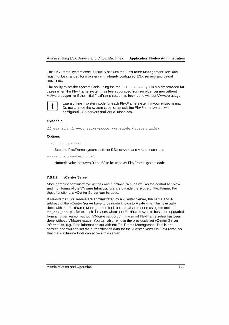
Administrating ESX Servers and Virtual Machines Application Nodes Administration
Administration and Operation 121
The FlexFrame system code is usually set with the FlexFrame Management Tool and
must not be changed for a system with already configured ESX servers and virtual
machines.
The ability to set the System Code using the tool ff_esx_adm.pl is mainly provided for
cases when the FlexFrame system has been upgraded from an older version without
VMware support or if the initial FlexFrame setup has been done without VMware usage.
Use a different system code for each FlexFrame system in your environment.
Do not change the system code for an existing FlexFrame system with
configured ESX servers and virtual machines.
Synopsis
ff_esx_adm.pl --op set-syscode --syscode <system code>
Options
--op set-syscode
Sets the FlexFrame system code for ESX servers and virtual machines.
--syscode <system code>
Numeric value between 0 and 63 to be used as FlexFrame system code
7.8.2.2 vCenter Server
More complex administrative actions and functionalities, as well as the centralized view
and monitoring of the VMware Infrastructure are outside the scope of FlexFrame. For
these functions, a vCenter Server can be used.
If FlexFrame ESX servers are administrated by a vCenter Server, the name and IP
address of the vCenter Server have to be made known to FlexFrame. This is usually
done with the FlexFrame Management Tool, but can also be done using the tool ff_esx_adm.pl, for example in cases when the FlexFrame system has been upgraded
from an older version without VMware support or if the initial FlexFrame setup has been
done without VMware usage. You can also remove the previously set vCenter Server
information, e.g. if the information set with the FlexFrame Management Tool is not
correct, and you can set the authentication data for the vCenter Server in FlexFrame, so
that the FlexFrame tools can access this server.

Application Nodes Administration Administrating ESX Servers and Virtual Machines
122 Administration and Operation
Synopsis
ff_esx_adm.pl --op vcenter-add --vc-name <vcenter name>
[--vc-ip <vcenter ip>] [--vc-in-cntllan]
ff_esx_adm.pl --op vcenter-rem
ff_esx_adm.pl --op vcenter-auth --user <user name>
--pass <password>
Options
--op vcenter-add
Add vCenter Server hostname and IP address to FlexFrame.
--op vcenter-rem
Remove vCenter Server information from FlexFrame.
--op vcenter-auth
Set authentication data for vCenter Server in FlexFrame.
--vc-name <vcenter name>
Defines the name of the vCenter Server with --op vcenter-add.
--vc-ip <vcenter-ip>
Defines the IP address of the vCenter Server with --op vcenter-add. It can be
an address in the FlexFrame Control LAN or an address outside FlexFrame, that is
reachable from the Control Nodes.
If the --vc-ip option is omitted, and --vc-in-cntllan is specified, a free
address from Control LAN is selected.
--vc-in-cntllan
Specifies that the vCenter IP address is in the Control LAN. If no address is given,
advises the script to select a free address from Control LAN.
--user <user name>
Specifies the user name for accessing the vCenter Server.
--pass <password>
Specifies the password for accessing the vCenter Server.

Administrating ESX Servers and Virtual Machines Application Nodes Administration
Administration and Operation 123
If using vCenter Server in FlexFrame, the names and IP addresses of the ESX servers
must be resolvable on a DNS server that is accessible for the vCenter Server.
The FlexFrame ESX servers must be added manually to vCenter Server using their
hostnames as they are known in FlexFrame. Add the ESX servers to a Datacenter called
FlexFrame or, if more than one FlexFrame system is administrated with the same
vCenter Server, use a distinct Datacenter called FlexFrame-<i> for each FlexFrame
system, where i is the FlexFrame system code explained in section 7.8.2.1.
7.8.2.3 Control LAN Default Router for ESX Servers
If FlexFrame ESX servers are administrated by a vCenter Server, it may also be
necessary to use a Control LAN router that is set on the ESX servers as default router.
This can be done using the tool ff_esx_adm.pl with operation mode defrouter.
With this operation mode, the address of a default router for the Control LAN can be set
or removed in the FlexFrame configuration, including the DHCP configuration. The ESX
servers get this address via DHCP together with the IP address for ESXi management.
Synopsis
ff_esx_adm.pl --op defrouter --defrouter <default router ip | 0>
Options
--op defrouter
Add or remove the address of the Control LAN default router to the FlexFrame
configuration
--defrouter <default router ip | 0>
Defines the IP address of the Control LAN default router. Specify a Control LAN
address to add a default router for the ESXi hosts or to change the current setting, or
use the value 0 to remove it.

Application Nodes Administration Administrating ESX Servers and Virtual Machines
124 Administration and Operation
7.8.3 Adding ESX Servers
This section describes how to add an ESXi server to an existing FlexFrame environment.
Synopsis
ff_esx_adm.pl --op add --type <system type> --name <node name>
--swgroup <switch group_ id> --mac <mac addresses>
[--host <ip host number>[,<IPMI ip host number>
[,<2nd IPMI ip host number>]]]
[--slot <cabinet_id/slot>] [--10gbit]
[--mgmtswgroup <switch group id>]
[--port switch:port,switch:port,switch:port
[,switch:port]]
Options
--op add
Adds an ESX server node and displays some information about processing steps.
--type <system type>
Specifies the product name and type. Call ff_esx_adm.pl --help to get a list of
supported system types
--name <node name>
The name of the ESX server node. This name has to be unique for the entire
FlexFrame system. All interface names are based on this node name. The name has
to be lowercase and consists of 2 up to 13 characters (letters, digits and dashes). It
must start with a letter and must not end with a dash.
--swgroup <switch group id>
Defines the switch group the ESX server node is connected to. This information is
necessary to assign and configure switch ports. Call ff_esx_adm.pl --help to
get a list of currently configured switch group IDs.
For blade servers, the --swgroup option may be omitted, as the switch group is
already defined with the blade cabinet.

Administrating ESX Servers and Virtual Machines Application Nodes Administration
Administration and Operation 125
--mac <mac addresses>
Add here the MAC addresses of the server's data NICs.They are used to configure
DHCP. Use the colon separated hex notation for each MAC address. Concatenate
the two MAC addresses with a comma. A MAC address syntax example is
00:e0:00:c5:19:41.
For blade servers, the --mac option may be omitted. The MAC addresses are then
fetched via SNMP from the management blade.
--host <ip host number>[,<IPMI ip host number>
[,2nd IPMI ip host number>]]
Host part to be used to build the IP addresses for ESXi management and,
depending on system type, for IPMI, all of them in the Control LAN.
If the --host option is omitted, the script uses free host numbers to calculate the IP
addresses.
--slot <cabinet_id/slot>
With PRIMERGY server blades use this option to define the cabinet and slot ID of
the server blade. New cabinets have to be defined with the
ff_bx_cabinet_adm.pl command.
--mgmtswgroup <switch group id>
Defines the switch group the ESX servers management interface (IPMI) is
connected to. If omitted the effective switch group is computed as follows: If the
switch group given with --swgroup is no NEXUS switch group that switch group is
used else the switch group the NEXUS switch management interfaces are
connected is used. Call ff_esx_adm.pl --help to get a list of currently
configured switch group IDs.
--10gbit
Specifies that the node is used with 10 Gigabit data NICs. The specification can be
omitted if the nodes system_type only allows usage with 10 Gigabit data NICs.
--port switch:port,switch:port,switch:port,[switch:port]
Defines the switch ports to be used. First two tuples are for data NIC 1 and 2 and allocated in the switch group defined with --swgroup. The following tuples are for
mgmt NICs and allocated in the effective switch group for management interfaces. If
--10gbit is specified, the first two ports must be 10 Gigabit capable ports
If --port is not specified, the script assigns free ports according to an internal
algorithm.

Application Nodes Administration Administrating ESX Servers and Virtual Machines
126 Administration and Operation
Example
cn1:~ # ff_esx_adm.pl --op add --name rx300s5-esx1 --type RX300S5 --
swgroup 2
--mac 00:19:99:48:e2:aa,00:19:99:48:e2:ab
update LDAP
.........
update switch 2/1 configuration
Notice: Update will take about 1 minute.
restart cluster service dhcpd
stopping dhcpd (timeout=20) . dhcpd:done . done.
starting dhcpd (timeout=20) .. dhcpd:done . done.
Connect your systems LAN interfaces to named switch ports:
LAN Interface SwGroup / Switch / Port
data NIC-1 2 / 2 / 2
data NIC-2 2 / 1 / 2
IPMI NIC-1 2 / 2 / 24
The script first checks all arguments and aborts with an error message in case of errors. It
then fetches free IP addresses and switch ports or checks whether the given ones can be
used for the node. LDAP data are created and the switch ports are reconfigured to match
the requirements. The DHCP service on the control nodes is reconfigured to assign the
ESXi management IP address in the Control LAN based on the given MAC addresses.
At the end, you get a cabling advice if the node must be connected to a switch group.
How to continue
The next step is to do the cabling according to the advice if applicable.
Then proceed with installing/booting ESXi and preconfiguring the ESXi server using the
Direct Console User Interface (see section "Getting Started with ESX Servers and VMs"
on page 118 and the sections "Install and boot ESXi" and "ESXi Preconfiguration on the
Server Console" of the manual "Installation of a FlexFrame Environment").
Finally, complete the ESX server configuration as shown in the next section.
7.8.4 Completing ESX Server Configuration
This section describes how to complete the ESXi server configuration.
Synopsis
ff_esx_adm.pl --op complete-config [--name <node name>]
--user <user name> --pass <password>

Administrating ESX Servers and Virtual Machines Application Nodes Administration
Administration and Operation 127
Options
--op complete-config
Completes the ESX server configuration and stores the authentication data needed
to access the ESX server in FlexFrame for subsequent access of the server.
--name <node name>
Name of the ESX server node. If the name is omitted, the operation is done for all
defined ESX server nodes. This possibility is intended for usage during the
installation process.
--user <user name>
Specifies the user name for accessing the ESX server.
--pass <password>
Specifies the password for accessing the ESX server.
Example
cn1:~ # ff_esx_adm.pl --op complete-config --name rx300s5-esx1 --user
root
--pass password
The script accesses the ESXi server using the given authentication data and completes
the ESXi server configuration to match the FlexFrame needs, e.g. the FlexFrame Control
Nodes are set as NTP servers and as trap targets for SNMP. If it is already known for
which pools the ESXi server must be prepared, the corresponding Port Groups and
Datastores are created on the ESXi server (see section "ESX Servers and Pools" on
page 131 for details).
Finally, the script stores the authentication data needed to access the ESXi server to
enable the subsequent access of the server by FlexFrame scripts.
7.8.5 Removing ESX Servers
To remove an ESX server node from the FlexFrame configuration, the only needed
parameter is the node name. The node is removed from the LDAP database, the hosts
file and the DHCP configuration. The switch ports used by this node are also
unconfigured. An ESX server cannot be removed if there are still virtual machine
Application Nodes that use this ESX server in the FlexFrame configuration.
Please make sure that you really want to remove the ESX server node, as the
script does not ask for confirmation.

Application Nodes Administration Administrating ESX Servers and Virtual Machines
128 Administration and Operation
Synopsis
ff_esx_adm.pl --op rem --name <node name>
Options
--op rem
Removes an ESX server node from the FlexFrame configuration.
--name <node_name>
Name of the ESX server node.
Example
cn1:~ # ff_esx_adm.pl --op rem --name rx300s5-esx1
7.8.6 Displaying Information about ESX Servers and VMs
Using the script ff_esx_adm.pl, one can get an overview about all ESX servers, or
detailed information about a specific ESX server including its virtual machines.
With ff_esx_vm.pl, it is possible to get an overview of all FlexFrame virtual machines,
irrespective of the involved ESX server.
Synopsis
ff_esx_adm.pl --op list-all
ff_esx_adm.pl --op list --name <node name> [--cmdline]
Options
--op list-all
Displays an overview of all ESX server nodes and also shows ESX related global
FlexFrame parameters, such as the vCenter Server name and address or the
FlexFrame system code or ESXi servers and virtual machines.
--op list
Displays detailed information about a specific ESX server, including its virtual
machines.
--name <node name>
Name of the ESX server node.

Administrating ESX Servers and Virtual Machines Application Nodes Administration
Administration and Operation 129
--cmdline
Used with --op list, the command line that can be used to recreate the ESX
server node is displayed at the end of the node listing.
Synopsis
ff_esx_vm.pl --op list-all
Options
--op list-all
Displays an overview of all FlexFrame virtual machines, irrespective of the ESX
host.
Examples
Overview of all ESX servers and global information:
cn1:~ # ff_esx_adm.pl --op list-all
Global information
vCenter Server Hostname: vcenter-co
vCenter Server IP: 10.10.13.94
FlexFrame Systemcode: 1
Control LAN Default Router: 10.10.13.99
ESX Nodes sorted by name
bx31-esx
Node Type: BX620S4
Cabinet/Slot ID: 3/1
ESX mgmt IP/Hostname: 10.10.13.18 / bx31-esx
Mac Addr.: 00:1b:24:2d:ab:03 00:1b:24:2d:ab:04
bx33-esx
Node Type: BX620S4
Cabinet/Slot ID: 3/3
ESX mgmt IP/Hostname: 10.10.13.93 / bx33-esx
Mac Addr.: 00:1b:24:2d:a0:01 00:1b:24:2d:a0:02
rx300s5-esx1
Node Type: RX300S5
ESX mgmt IP/Hostname: 10.10.13.16 / rx300s5-esx1
Mac Addr.: 00:19:99:48:e2:aa 00:19:99:48:e2:ab

Application Nodes Administration Administrating ESX Servers and Virtual Machines
130 Administration and Operation
Detailed information about a specific ESX server:
cn1:~ # ff_esx_adm.pl --op list --name rx300s5-esx1
Configuration details of ESX node rx300s5-esx1
Hardware
System: RX300S5
10GBit: No
Shut.Facil.: IPMI rx300s5-esx1-co (10.10.13.27)
Mac Addr.: 00:19:99:48:e2:aa 00:19:99:48:e2:ab
ESX management interface (Control LAN)
Host IP: 10.10.13.16
Hostname: rx300s5-esx1
LAN Interface Connections
LAN Interface SwGroup / Switch / Port
data NIC-1 2 / 2 / 2
data NIC-2 2 / 1 / 2
IPMI NIC-1 2 / 2 / 24
ESX resources
Product Name: VMware ESXi 5.0.0 build-474610
Memory Size: 8179 MB
CPU Cores: 8
License Name: VMware vSphere 5 Enterprise Plus
List of Virtual Machine - Application Nodes:
Name Pool Group State CPUs Memory
lin-vm13 pool1 p1-vms Off 2 2048
lin-vm21 pool2 p2-vms Off 2 2048
Overview of all FlexFrame virtual machines:
cn1:~ # ff_esx_vm.pl --op list-all
List of Virtual Machine - Application Nodes registered in LDAP
VM-AN Name Pool Group ESX Host
lin-vm11 pool1 p1-vms bx31-esx
lin-vm13 pool1 p1-vms rx300s5-esx1
lin-vm2 pool1 p1-vms bx33-esx
lin-vm21 pool2 p2-vms rx300s5-esx1
lin-vm23 pool2 p2-vms bx33-esx
lin-vm39 pool3 p3-vms bx33-esx
Collecting information from ESX Hosts:

Administrating ESX Servers and Virtual Machines Application Nodes Administration
Administration and Operation 131
rx300s5-esx1 ... done
bx31-esx ... done
bx33-esx ... done
List of FlexFrame Virtual Machines found on available ESX servers
VM Name ESX Host State
lin-vm11 bx31-esx On
lin-vm13 rx300s5-esx1 Off
lin-vm2 bx33-esx On
lin-vm21 rx300s5-esx1 Off
lin-vm23 bx33-esx On
lin-vm39 bx33-esx Off
7.8.7 ESX Servers and Pools
An ESX server can host virtual machine Application Nodes from different pools. For each
pool the server needs some specific resources, such as a virtual machine Port Group for
each of the pool networks and two datastores (config and software) in the pool specific
volFF volume of the pool.
Usually, these resources are implicitly prepared when the first virtual machine Application
Node of a pool is created on an ESX server, so that there is no need to do an explicit pool
preparation of the ESX server.
However, if a FlexFrame virtual machine is moved to another ESX server by mechanisms
outside FlexFrame (see also section 7.8.10), these resources must be prepared in
advance. This can be done by using the add-pool operation of the ff_esx_adm.pl
script.
Synopsis
ff_esx_adm.pl --op add-pool --name <node name> --pool <pool name>
Options
--op add-pool
Prepares an ESX server for usage by virtual machine Application Nodes from given
pool.
--name <node name>
Name of the ESX server node.
--pool <pool name>
Name of the pool for which the ESX server must be prepared.

Application Nodes Administration Administrating ESX Servers and Virtual Machines
132 Administration and Operation
Example
cn1:~ # ff_esx_adm.pl --op add-pool --name rx300s5-esx1 --pool pool3
7.8.8 Special Functions for Virtual Machines
A virtual machine designated for use as a FlexFrame Application Node is usually created
when the Application Node is added to the FlexFrame configuration with ff_an_adm.pl
--op add. Likewise, the virtual machine is destroyed when the associated Application
Node is removed using ff_an_adm.pl --op rem.
Under special circumstances, it is necessary to create FlexFrame virtual machines for
Application Nodes already defined in LDAP, for example during the FlexFrame
installation process. For special purposes, it may also be helpful to destroy a FlexFrame
virtual machine while preserving its LDAP entry, or if the LDAP entry is missing, e.g. as
an effect of an Application Node removal that failed to destroy the virtual machine.
The script ff_esx_vm.pl provides these functionalities, as well as some other special
functions acting on virtual machines. This script is not intended for usual administrative
interactions with virtual machine Application Nodes. Use ff_an_adm.pl to administrate
these Application Nodes too in almost the same manner as other Application Nodes.
Synopsis
ff_esx_vm.pl --op create [--name <node name>]
[--esx <node name>]
[--vcpus <number of virtual cpus>]
[--vmem <virtual machine memory size]
[--force]
ff_esx_vm.pl --op destroy --name <nodename> [--force]
ff_esx_vm.pl --op move --name <node name>
--to-esx <node name>
ff_esx_vm.pl --op refresh-ldap [--name <node name>]
ff_esx_vm.pl --op list --name <node name>
ff_esx_vm.pl --op list-all

Administrating ESX Servers and Virtual Machines Application Nodes Administration
Administration and Operation 133
Options
--op create
Creates virtual machines that are already defined in the FlexFrame configuration
database (LDAP). If called without option --name, a virtual machine is created for
each Application Node with system type ESXVM found in LDAP. Otherwise, only the
Application Node with the specified name is considered. The virtual machines get
the same names as the Application Nodes. The target ESXi server, the number of
virtual CPUs and the memory size of the virtual machine are taken from LDAP by
default, but can be overridden using the options --esx, --vcpus and --vmem.
--op destroy
Destroys a FlexFrame virtual machine while preserving its LDAP entry or if the
LDAP entry is missing. If the LDAP entry is missing, the operation is started only if
the option --force is specified.
--op move
Moves a powered off FlexFrame virtual machine to another ESXi server.
--op refresh-ldap
Adjusts the LDAP information for a specific or for all virtual machine Application
Node(s) after changes done with mechanisms outside FlexFrame, e.g. when a
virtual machine has been moved to another ESXi host by VMware HA. For more
information about using other mechanisms on FlexFrame virtual machines see
section 7.8.10 below.
--op list
Displays information about a specific FlexFrame virtual machine.
--op list-all
Displays information about all FlexFrame virtual machines. See also section 7.8.6.
--name <node name>
The name is used to identify a specific node. If specified, an Application Node with
this name and system type ESXVM must exist in LDAP, except for the case when
the --force option is specified with --op destroy.
--esx <node name>
Specifies the node name of the ESXi host where the virtual machine must be
created. By default, the value from LDAP is used. When no <node name> is given,
the --esx option is used to select all VMs for creation for which the specified ESXi
host is preset in LDAP.

Application Nodes Administration Administrating ESX Servers and Virtual Machines
134 Administration and Operation
--vcpus <number of virtual cpus>
Defines the number of virtual CPUs when creating a virtual machine. By default, the
value from LDAP is used. The argument must be a number between 1 and 8.
Moreover, the available resources of the ESXi host must be taken into account. See
also section 7.8.9 below.
--vmem <virtual machine memory size>
Defines the memory size in MB when creating a virtual machine. By default, the
value from LDAP is used. The memory size must be a number between 256 and
261120 (=255GB). Moreover, the available resources of the ESXi host must be
taken into account. See also section 7.8.9 below.
--force
Specifies that the memory usage of the ESXi host may be overcommitted when
creating virtual machines. Default is to deny creation of virtual machines on a host if the total vmem of the virtual machines on this host, including the new ones, exceeds
the memory size of the host. With operation mode destroy, --force allows to
destroy a FlexFrame virtual machine even when no corresponding LDAP entry
exists.
--to-esx <node name>
This option is used with --op move to specify the name of the target ESXi server.
7.8.9 Virtual Machine Properties and ESXi Resources
In a vSphere environment, ESX/ESXi hosts provide resources for virtual machines.
Resources include CPU, memory, power, storage and network resources. In this section,
we focus on CPU and memory resources, as well as on storage requirements.
As a part of the virtual hardware properties, the memory size and the number of virtual
CPUs are defined when creating a virtual machine. In a FlexFrame environment, values
for these parameters are either predefined with the FlexFrame Management Tool for
each virtual machine Application Node and can be later overridden when creating the
virtual machine using the ff_esx_vm.pl script, or are defined when creating the
Application Node including its virtual machine with ff_an_adm.pl.
When choosing values for these parameters, a careful planning must be done that takes
into account which machines will be powered on on a given ESX server at the same time
and for what kind of SAP workload they are planned to be used.
VMware techniques allow to configure more memory for the virtual machines on an ESX
server than the available physical memory of the host. This feature is called memory
overcommit and basically assumes that a VM does not use all assigned memory and
therefore it can be shared with other VMs.

Administrating ESX Servers and Virtual Machines Application Nodes Administration
Administration and Operation 135
For SAP systems it is strongly recommended not to overcommit memory usage, because
SAP allocates memory permanently and does not release it again. Furthermore, a
minimum of 4GB should be used, and for Unicode systems, a minimum of 8GB.
You should also be aware that if the memory size defined for a virtual machine is not
sufficient for the workload, excessive Linux swapping in the virtual machine may occur
which has a negative impact on performance and leads to an increased I/O load on the
filer and network which may even disturb the correct operation of the system.
A virtual machine can be configured with up to eight virtual CPUs, but it cannot be
powered on if it has more CPUs than the number of logical processors of the host - that is
the number of physical processor cores if hyperthreading is disabled or two times the
number of physical processor cores if hyperthreading is enabled. Similarly as with
memory, VMware techniques allow to overcommit processor usage. When a host runs
multiple virtual machines that require more than the available CPU resources, the host
time-slices the physical processors across all virtual machines so that each virtual
machine runs as if it has its specified number of virtual processors. The CPU virtualization
adds varying overhead with performance implications.
SAP has successfully run performance tests in vSphere virtual machines (utilizing all
available virtual CPUs to 100%) which overcommitted the host system up to 200%. The
performance degradation inside the virtual machines was linear reciprocal to the
overcommitment. You may exceed the 200% overcommitment, but keep in mind, that the
performance of virtual machines in such a scenario is not guaranteed. In case of
performance problems, SAP can demand you to shutdown or pause other running virtual
machines to check if the overcommitment caused problems.
When creating virtual machines using FlexFrame scripts, the parameters given for the
memory size and the number of virtual CPUs (--vmem and --vcpus) are roughly
checked for plausible values and it is checked that the memory usage of the designated
ESX server is not overcommitted, but no further checks and resource evaluations are
carried out. This task is in the responsibility of the specialists that make the configuration
and sizing planning for the FlexFrame system and assumes a good knowledge of the
virtualization techniques and the requirements of the used SAP systems.
A FlexFrame virtual machine also needs some space on the pool specific volFF of the
pool to which the Application Node belongs. The most significant resources located here
are the file representing the virtual hard disk of the virtual machine (vmdk) and the file
used by the VMkernel to swap out the virtual machine‘s physical memory in certain
shortage cases (vswp). The size of the vmdk file is defined by the size of the virtual hard
disk, which is 36 GB for FlexFrame virtual machines. The size of the vswp file is
correlated to the memory size of the virtual machine. If there is not sufficient space
available, the creation of the virtual machine may fail or the virtual machine fails to start.
These space requirements must also be taken into account during the configuration and
sizing planning mentioned above.

Application Nodes Administration Administrating ESX Servers and Virtual Machines
136 Administration and Operation
7.8.10 Using vSphere Functions for FlexFrame Objects
While the FlexFrame tools focus mainly on the FlexFrame specific aspects of ESXi
servers and virtual machines, there are other ways to access vSphere components, such
as the vSphere Client or the vSphere Command-Line Interface (vCLI). Moreover, for
more complex administrative actions and functionalities, as well as the centralized view
and monitoring of the VMware Infrastructure, a vCenter Server can be used
These tools and functions are outside the scope of FlexFrame, and for information on
their usage please refer to the appropriate VMware documentation.
However, when using them for ESX servers and virtual machines known in FlexFrame, it
must be taken care not to disturb the FlexFrame functionality. Some special requirements
are:
1. Virtual machines for FlexFrame usage must be created using FlexFrame tools
2. Do not rename FlexFrame virtual machines
3. Do not destroy FlexFrame virtual machines while the associated Application Node
still exists. Removing the Application Node usually also destroys the virtual machine.
4. Do not change the virtual machine properties and devices. As an exception, you may
change the number of CPUs and the memory size of an powered off virtual machine,
but take into account the resources of the involved ESX server. After such changes,
please call ff_esx_vm.pl --op refresh-ldap to adjust the corresponding
LDAP settings, or use the script ff_ponpoff.pl to power on the virtual machine,
as this does an implicit refresh of the LDAP settings.
5. Do not move a FlexFrame virtual machine to an ESX server that is not part of the
same FlexFrame system. To move a powered off virtual machine to another ESX
server of the FlexFrame system, you can use ff_esx_vm.pl --op move.
Otherwise, you must also take care that the target ESX server is prepared for the
pool the virtual machine Application Node belongs to. After a move done with non-
FlexFrame tools, please call ff_esx_vm.pl --op refresh-ldap to adjust the
corresponding LDAP setting as soon as possible.
6. Do not suspend/resume FlexFrame virtual machines. This may result in a service
being executed twice when a service formerly running on the suspended virtual
machine has been moved to a spare node and then the other VM is resumed. To
enforce this requirement, the FlexFrame scripts create an alarm on vCenter server (if
known in FlexFrame, including authentication data) that powers off a virtual machine
when it is resumed.
For virtual machines created by FlexFrame on ESXi 5.0 hosts, a special attribute is
set which denies the suspend action on these virtual machines.

Script for Power on/off/Reboot of a Computing Node in FF4SApplication Nodes Administration
Administration and Operation 137
7.9 Script for Power on/off/Reboot of a Computing Node in FF4S
7.9.1 Synopsis
ff_ponpoff.pl --op power-on | power-off | reboot
--name <node name | @all>
--op power-on power-on the node(s)
power-off power-off the node(s)
reboot reboot the node(s)
--node <node name> execute the above actions for a single node <node name>
@all execute the above actions for all nodes of a FlexFrame
The script takes the shutdown configuration files from /opt/myAMC/vFF/vFF_<pool
name>/config/myAMC_FA_SD_Sec.xml to get shutdown-users and –passwords, and
in case of server blades, gets the address of the management blade. The content of
these configuration files is supplied during the installation process of a FlexFrame, or it
can be actualized late by the FA Agents (see also FlexFrame Installation Guide V5.1A
Power Shutdown Configuration). It can happen that a certain node isn't in the appropriate
configuration file: You can write it manually into it, or answer the procedure's prompts for
user and password.

Storage Systems Administration NAS Systems Configuration (EMC and NetApp)
138 Administration and Operation
8 Storage Systems Administration
8.1 NAS Systems Configuration (EMC and NetApp)
8.1.1 Adding a New NAS
To add a NAS to FlexFrame environment the NAS has to be configured, the network
prepared and some data has to be stored at LDAP database. The NAS configuration has
to be done manually. But all necessary data and locations are displayed by this program.
The network and LDAP preparation is done directly by ff_nas_adm.pl.
Synopsis
ff_nas_adm.pl --op add --name <node name> --type <sytem type>
--swgroup <switch group id> [--host <ip host part>]
[--ports <port count>] [--blades <blade count>]
[--partner <node name>]
[--cstations <control station count>]
[--shcmd <shell command>]
[--10gbit]
Options
--op add
Adds a NAS and displays some information about processing steps.
--name <node name>
Defines the node name of the NAS. The name may consist of 2 upt to 13 characters
(letters, digits and dashes). It must start with a letter and must not end with a dash.
--type <systemtype>
Defines the type of the NAS. See usage for a list of known NAS types.
--swgroup <switch group id>
Defines the switch group the NAS should be added to. See usage for a list of
configured switch group IDs.
--host <ip host part>
Defines the host part to be used to build IP addresses for the Control or Storage
LAN networks. If this option is omitted the script uses a free host number to calculate
the IP address.

NAS Systems Configuration (EMC and NetApp) Storage Systems Administration
Administration and Operation 139
--ports <port count>
Defines the count of ports to be used with pool Storage LAN networks. If this option
is omitted the script uses the default of two ports. The maximum number of ports per
channel is 8 (dependant on hardware capabilities)..
--blades <blade count>
Blade/data mover count of an EMC Celerra NAS. If this option is omitted the script
uses the default of one blade.
--partner <node name>
Defines the cluster partner in a NetApp filer cluster or the remote partner for an EMC
Celerra.
--cstations <control station count>
Count of control stations of an EMC Celerra NAS. If this option is omitted the script
uses the default of one control station.
--shcmd <shell command>
Shell command (absolute path) used to configure NAS.
If this option is omitted the script uses the default (/usr/bin/ssh).
--10gbit
NAS is a 10Gbit system. This option is only usable for NetApp Filers.
Example for a NetApp Filer
cn1:/opt/FlexFrame/bin # ff_nas_adm.pl --op add --name filer2 --type FAS3000
--swgroup 1
update LDAP
.....
update switch 1/1 configuration
Notice: Update will take about 1 minute.
................................+
Some manual interventions are necessary to integrate the NAS
into FlexFrame environment.
The following list of actions has to be performed in order to integrate the NAS
into your FlexFrame landscape. Since your exact configuration may vary, these steps
have to be performed manually. However, the VIF must be named 'storage'.
The /etc/rc, /etc/exports and /etc/hosts.equiv have to be edited
at volume vol0.
These lines have to be added to or changed at /etc/rc:

Storage Systems Administration NAS Systems Configuration (EMC and NetApp)
140 Administration and Operation
hostname filer2
vif create multi storage <-- add your NICs here, eg. e0a e0b for 1GB/sec ports;
e1 e2 for 10GB/sec ports.
vlan create storage 13
ifconfig storage-13 192.168.20.4 netmask 255.255.255.0 broadcast 192.168.20.255
mtusize 1500 -wins up
options dns.enable off
options nis.enable off
savecore
These lines have to be added to or changed at /etc/exports:
/vol/vol0 -sec=sys,rw=192.168.20.2:192.168.20.1,anon=0
These lines have to be added to /etc/hosts.equiv:
192.168.20.2 root
192.168.20.1 root
As the switch ports are already configured the correct wiring between NAS and
switch ports has to be done. See below a list of cable connections.
Connect your NAS LAN interfaces to named switch ports:
SwitchGroup / Switch / Port LAN Interface
1 / 2 / 3 filer2 (FAS3000): port "data NIC-1"
1 / 1 / 3 filer2 (FAS3000): port "data NIC-2"
Finally execute command "mount /FlexFrame/filer2/vol0"
on both Control Nodes to mount filers vol0 at Control Nodes. This is necessary for
further automated configuration of filer.
The complete instruction above is listed at file /tmp/filer2-add/todo

NAS Systems Configuration (EMC and NetApp) Storage Systems Administration
Administration and Operation 141
Example for an EMC Celerra:
cn1:~ # ff_nas_adm.pl --op add --name emc01 --type NS-TYPE --swgroup 1 --blades 2
update LDAP
...........
update switch 1/1 configuration
Notice: Update will take about 1 minute.
.........................................................................+
Some manual interventions are necessary to integrate the NAS
into FlexFrame environment.
The following list of actions has to be performed in order to integrate
the NAS into your FlexFrame landscape. Since your exact configuration
may vary, these steps have to be performed manually.
As the switch ports are already configured the correct wiring between
NAS and switch ports has to be done. See below a list of cable
connections.
Connect your NAS LAN interfaces to named switch ports:
SwitchGroup / Switch / Port LAN Interface
1 / 2 / 8 emc01 (NS-TYPE): server_2: port "data NIC-1"
1 / 1 / 8 emc01 (NS-TYPE): server_2: port "data NIC-2"
1 / 2 / 9 emc01 (NS-TYPE): server_3: port "data NIC-1"
1 / 1 / 9 emc01 (NS-TYPE): server_3: port "data NIC-2"
1 / 2 / 20 emc01 (NS-TYPE): port "mgmt NIC-1"
Mounting of any Celerra filesystems to Control Nodes is not
necessary for further configuration.
The complete instruction above is listed at file /tmp/emc01-add/todo
8.1.2 Removing a NAS
To remove a NAS from FlexFrame landscape it must not be used by any pool.
ff_nas_adm.pl --op list will display the current configuration of the NAS.
The switch port configuration will be removed from switches and LDAP database.
Synopsis
ff_nas_adm.pl --op rem --name <node name>

Storage Systems Administration NAS Systems Configuration (EMC and NetApp)
142 Administration and Operation
Options
--op rem
Removes a NAS from FlexFrame landscape about the NAS configuration and
displays some information about processing steps.
--name <node name>
Defines the node name of the NAS.
Example
cn1:/opt/FlexFrame/bin # ff_nas_adm.pl --op rem --name filer2
update switch 1/1 configuration
Notice: Update will take about 1 minute.
.............................+
update LDAP
.....
NAS successfully removed from network and LDAP.
8.1.3 Configuring SNMP Traps for NetApp Filers
The NetApp Filers within FlexFrame should send their messages (SNMP traps) to the
Control Nodes (resp. myAMC.Messenger). This has to be configured on the Filers side.
Therefore logon to the Filer(s) with telnet <filer> and continue with the following
steps:
filer> snmp traphost add 192.168.20.1
filer> snmp traphost add 192.168.20.2
Use IP addresses of the Control LAN segment.
filer> snmp community add ro public
public may be replaced by the community you have specified in the
Management Tool.
For further information how to configure thresholds on Filer specific traps, please see the
NetApp Filer documentation.

NAS Systems Configuration (EMC and NetApp) Storage Systems Administration
Administration and Operation 143
8.1.4 Displaying all configured NAS
To get an overview of all configured NAS within the FlexFrame environment use the operation mode list-all of the program ff_nas_adm.pl. It displays IP addresses
and names, type, switch ports and the link aggregation id, separated by NAS.
Synopsis
ff_nas_adm.pl --op list-all
Option
--op list-all
Displays all configured NAS.
Example
cn1:/opt/FlexFrame/bin # ff_nas_adm.pl --op list-all
NAS configurations
filer
Control Lan
192.168.20.3 filer-co
Type: FAS3000
Shell: /usr/bin/ssh -l flexframe
Switch Link Aggregation
Port Count: 2
Link Aggr.ID: 5
Storage LAN switch ports
1 / 1 / 13 SwGroup / Switch / Port
1 / 2 / 13 SwGroup / Switch / Port
Control LAN switch ports
1 / 2 / 15 SwGroup / Switch / Port
Pools
pool1 192.168.2.131 filer-pool1-st master
pool2 10.3.1.3 filer-pool2-st master
pool5 192.168.40.3 filer-pool5 master
usr 192.168.5.3 filer-usr-st master
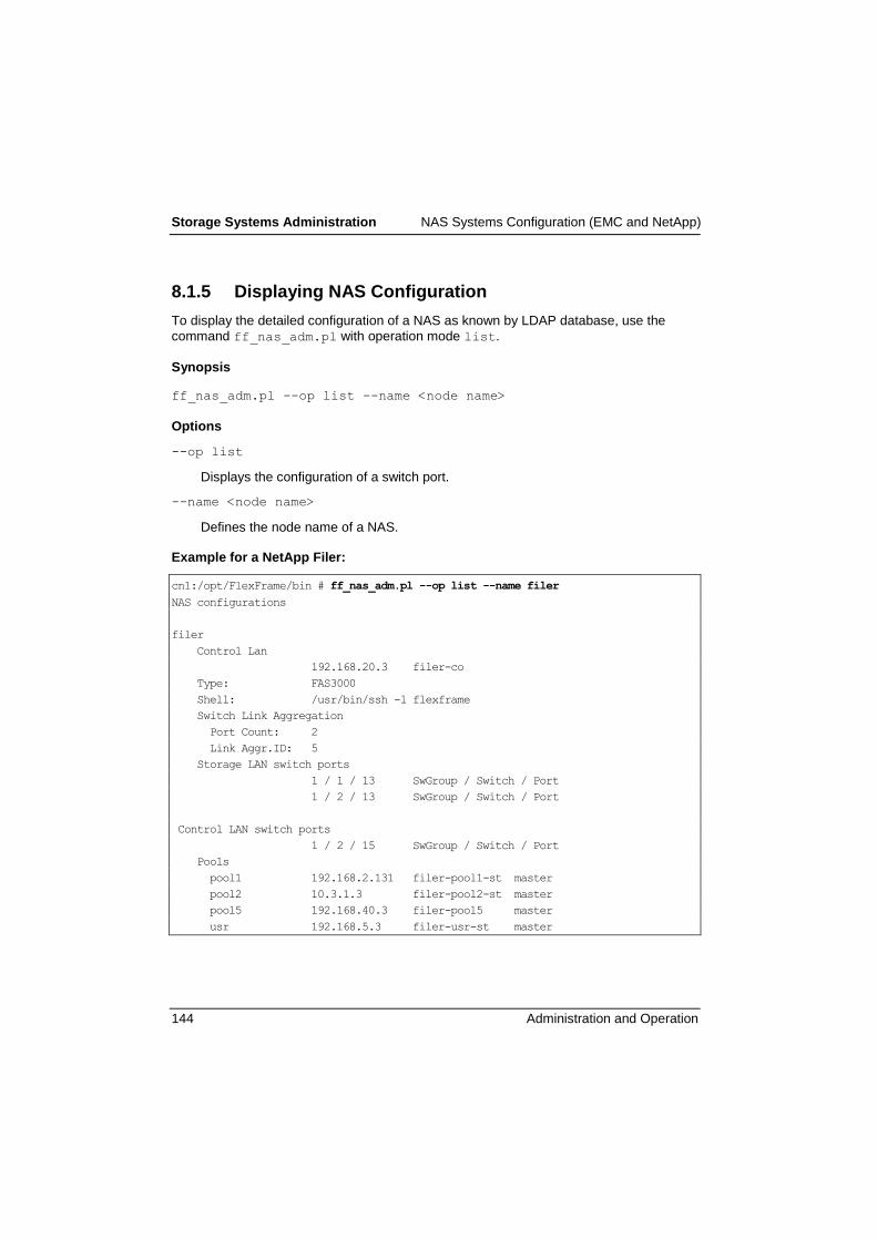
Storage Systems Administration NAS Systems Configuration (EMC and NetApp)
144 Administration and Operation
8.1.5 Displaying NAS Configuration
To display the detailed configuration of a NAS as known by LDAP database, use the
command ff_nas_adm.pl with operation mode list.
Synopsis
ff_nas_adm.pl --op list --name <node name>
Options
--op list
Displays the configuration of a switch port.
--name <node name>
Defines the node name of a NAS.
Example for a NetApp Filer:
cn1:/opt/FlexFrame/bin # ff_nas_adm.pl --op list --name filer
NAS configurations
filer
Control Lan
192.168.20.3 filer-co
Type: FAS3000
Shell: /usr/bin/ssh -l flexframe
Switch Link Aggregation
Port Count: 2
Link Aggr.ID: 5
Storage LAN switch ports
1 / 1 / 13 SwGroup / Switch / Port
1 / 2 / 13 SwGroup / Switch / Port
Control LAN switch ports
1 / 2 / 15 SwGroup / Switch / Port
Pools
pool1 192.168.2.131 filer-pool1-st master
pool2 10.3.1.3 filer-pool2-st master
pool5 192.168.40.3 filer-pool5 master
usr 192.168.5.3 filer-usr-st master

NAS Systems Configuration (EMC and NetApp) Storage Systems Administration
Administration and Operation 145
Example for an EMC Celerra:
cn1:~ # ff_nas_adm.pl --op list –name cel
NAS configurations
cel
Control Lan
192.168.100.204 cel-co
192.168.100.205 celcs1-co ControlStation1 priv.
192.168.100.206 celcs2-co ControlStation2 priv.
Type: NS-Type
Shell: /usr/bin/ssh
Switch Link Aggregation
DataMover Port Count Link Aggr.ID
2 2 5
Storage LAN switch ports
DataMover SwGroup / Switch / Port
Control LAN switch ports
1 / 1 / 20 SwGroup / Switch / Port
Pools
DataMover Pool IP Name
2 p1 192.168.11.204 cel-p1-st
8.1.6 Adding a Pool to a NAS
To be able to use an existing NAS for a pool, the network connection to the NAS has to
be enhanced. On the NAS, a new virtual interface has to be created and on the switch ports the new VLAN has to be configured. All these steps are done with ff_nas_adm.pl
using the operation mode add-pool, but the program will not change any exports.
For EMC NAS the switch ports to any data mover of an EMC Celerra are allowed for all
VLANs the NAS is using. So any data mover is able to take over the role of any other
data mover.
Synopsis
ff_nas_adm.pl --op add-pool --name <node name> --pool <pool name>
[--role {master|slave}] [--host <ip host part>]
[--blade <blade id>]
Options
--op add-pool
Adds the given pool to named NAS.

Storage Systems Administration NAS Systems Configuration (EMC and NetApp)
146 Administration and Operation
--name <node name>
Defines the node name of NAS.
--pool <pool name>
Defines the pool name the NAS has to be support. See usage for a list of configured
pools.
--role {master|slave}
Defines the role of NAS within given pool. This information is used by the ff_setup_sid_folder program. If this option is omitted the script uses the
default role master.
--host <ip host part>
Defines the host part to be used to build IP addresses for the Control or Storage
LAN networks. If this option is omitted, the script uses a free host number to
calculate the IP address.
--blade <blade id>
Blade/data mover Id of an EMC Celerra NAS. The Id is the numerical value of the
blade/ data mover (eg. server_2 means Id 2). If this option is omitted the script
uses the default of Id 2.
Example
cn1:/opt/FlexFrame/bin # ff_nas_adm.pl --op add-pool --name filer --pool pool4
update LDAP
....
update switch 1/1 configuration
Notice: Update will take about 1 minute.
...........+
vlan: storage-25 has been created
Pool pool4 successfully added to NAS, LDAP and network.
8.1.7 Removing a Pool from a NAS
The rem-pool mode is the opposite to the add-pool operation mode of
ff_nas_adm.pl. It removes the virtual interface to the pool and removes VLAN access
on NAS switch ports for the given pool. This action will not be permitted if any SID of the
pool uses this NAS or the NAS is the default NAS of the pool. Within the last case, the
pool interface of the NAS will be removed when removing the pool.
For EMC NAS the pool's VLAN will only be removed from EMC Celerra switch ports if no
longer any data mover is configured for this pool.
NAS Systems Configuration (EMC and NetApp) Storage Systems Administration
Administration and Operation 147
Synopsis
ff_nas_adm.pl --op rem-pool --name <node name> --pool <pool name>
--blade <blade id>
Options
--op rem-pool
Removes the given pool from the named NAS.
--name <node name>
Defines the node name of the NAS.
--pool <pool name>
Defines the pool name the NAS has to be support. See usage for a list of configured
pools.
--blade <blade id>
Blade/data mover Id of an EMC Celerra NAS. The Id is the numerical value of the
blade/ data mover, eg. server_2 means Id 2. If this option is omitted the script
uses the default of Id 2.
Example
cn1:/opt/FlexFrame/bin # ff_nas_adm.pl --op rem-pool --name filer --pool pool4
update switch 1/1 configuration
Notice: Update will take about 1 minute.
...........+
update LDAP
....
Pool pool4 successfully removed from NAS, LDAP and network.
8.1.8 Adding a Blade (Data Mover) to an EMC Celerra NAS
An EMC Celerra may consist of more than one data mover. To add one or more data
movers to an existing NAS use this command. It will add configuration data to LDAP and
assign and configure switch ports. It will display instructions how to interconnect the new
data movers with the FlexFrame switch group.
Synopsis
ff_nas_adm.pl --op add-blade --name <node name>
[--ports <port count>] [--blades <blade count>]

Storage Systems Administration NAS Systems Configuration (EMC and NetApp)
148 Administration and Operation
Options
--op add-blade
Adds blades/ data movers to NAS.
--name <node name>
Defines the node name of the NAS.
--ports <port count>
Count of ports to be used with pool storage lan networks. If this option is omitted the
program uses the default of 2.
--blades <blade count>
Number of blades/data movers to be added. If this option is omitted the program
uses the default of 1.
Example
cn1:~ # ff_nas_adm.pl --op add-blade --name cel
update LDAP
...
update switch 1/1 configuration
Notice: Update will take about 1 minute.
..................................+
As the switch ports are already configured the correct wiring between
DataMover and switch ports has to be done. See below a list of cable
connections.
Connect your DataMover LAN interfaces to named switch ports:
SwitchGroup / Switch / Port LAN Interface
1 / 2 / 11 cel (NS-Type): server_4: port "data NIC-1"
1 / 1 / 11 cel (NS-Type): server_4: port "data NIC-2"
The complete instruction above is listed at file /tmp/cel-add/todo
8.1.9 Removing a Blade (Data Mover) from an EMC Celerra NAS
To remove one data mover from an existing NAS use this command. It will remove con-
figuration data from LDAP and deactivate the corresponding switch ports.

NAS Systems Configuration (EMC and NetApp) Storage Systems Administration
Administration and Operation 149
Synopsis
ff_nas_adm.pl --op rem-blade --name <node name>
--blade <blade id>
Options
--op rem-blade
Removes blades / data movers from NAS.
--name <node name>
Defines the node name of the NAS.
--blade <blade id>
Blade/data mover Id to be removed. If this option is omitted the program uses the
default of 2.
8.1.10 Create NAS Cluster Partnership
Synopsis
ff_nas_adm.pl --op partner –-name <node name> --partner
<node name>
Options
--op partner
Define a cluster partnership for a NetApp filer cluster or an EMC Celerra.
--name <node name>
First partner in a NetApp filer cluster or an EMC Celerra cluster.
--partner <node name>
Second partner in a NetApp filer cluster or an EMC Celerra cluster.
8.1.11 Move a NAS to another Switch Group
A NAS may be moved from one switch group to another using operation mode move.
This includes moving from and to external (core) switches, distinguished by the switch
group id ‗0‘. During this process, the speed of the network connection may be changed
(even within one switch group by specifying the current switch group id and one of ‗—
1gbit‘ or ‗—10gbit‘).

Storage Systems Administration NAS Systems Configuration (EMC and NetApp)
150 Administration and Operation
Synopsis
ff_nas_adm.pl --op move --name <node name> --swgroup <switch group
id> [--mgmtswgroup <switch group id>]
[--1gbit|--10gbit}
Options
--op move
move a NAS to another switch group
--name <node name>
Defines the node name of the NAS.
--swgroup <switch group id>
Defines the switch group the data ports of the NAS should be moved to.
--mgmtswgroup <switch group id>
Defines the switch group for management ports. This is only relevant when moving
to a NEXUS5x00-VPC switch group. It defaults to the value defined with the switch
group.
--10gbit
move to 10 Gbit Connection .
--1gbit
move to 1Gbit Connection.
8.1.12 Switching a NetApp Filer between 1Gbit and 10Gbit
The named functionality, formerly available with operation mode conf 10gb, is now
supplied by operation mode move, above.
8.1.13 Changing NAS Command Shell
To change the command shell used to configure the NAS, the ff_nas_adm.pl
command supports the change_sh operation mode.
The given shell command replaces the currently used command or default configuring the
named NAS. To change the shell for more than one NAS the procedure has to be done
for each NAS.

NAS Systems Configuration (EMC and NetApp) Storage Systems Administration
Administration and Operation 151
Be sure there is no password request using this shell command to connect the
NAS.
Synopsis
ff_nas_adm.pl --op change-sh --name <node name>
--shcmd <shell command>
Options
--op change-sh
Changes the sh command for NAS configuration.
--name <node name>
Defines the node name of the NAS.
--shcmd <shell command>
Shell command (absolute path) used to configure NAS. If this option is omitted the
script uses the defaults /usr/bin/ssh for NetApp Filers and EMC Celerras.
Example
cn1:~ # ff_nas_adm.pl --op change-sh --name filer
–-shcmd '/usr/bin/ssh -l flexframe'
update LDAP
.
NAS shell command changed at LDAP.
Shell command changed to "/usr/bin/ssh -l flexframe".
8.1.14 Changing NAS LinkAggregate Ports
To change the count of NICs of the vif link aggregate the ff_nas_adm.pl commands
supports the change-ports operation mode. The given number is the count of NICs the
aggregate should contain. The difference between actual and given count of ports will be
allocated at switch group, proper configured and displayed at end of program run. The
additional wiring and configuration of NAS have to be done manually.
At EMC Celerra the link aggregates for all data movers/blades are expanded.

Storage Systems Administration NAS Systems Configuration (EMC and NetApp)
152 Administration and Operation
Synopsis
ff_nas_adm.pl --op change-ports --name <node name>
--ports <port count>
Options
--op change-ports
Change the count of NICs of link aggregate per Filer or data mover.
--name <node name>
Defines the node name of the NAS.
--ports <port count>
Count of NICs the link aggregate should contain.
Example
cn1:~ # ff_nas_adm.pl --op change-ports --name filer –-ports 4
update LDAP.
Expand StorageLAN vif with 2 NICs up to 4 NICs.
Do this before(!) connecting new NICs to switch ports.
The additional switch ports at Switch Group are already configured.
Interconnect additional NICs between NAS and the switches of
SwitchGroup 1 as noted below:
SwGrpID/SwitchID/Port Filer
1 / 1 / 20 <==> Filer data NIC-3
1 / 2 / 20 <==> Filer data NIC-4
Unless any errors are reported follow instructions above to extend
NAS link aggregate(s) to switch group.
Look at "/opt/FlexFrame/network/wiring-channel-extend-filer.txt"
to get a copy of this message.
8.1.15 NAS Disk Free
To get information on available space on NAS file systems, the program ff_nas_df.pl
may be used. It connects to all FlexFrame NAS and views the disk free (df) information.
To be comparable all size values are given as kilo bytes. The view may be restricted to a
single NAS.

NAS Systems Configuration (EMC and NetApp) Storage Systems Administration
Administration and Operation 153
Synopsis
ff_nas_df.pl [--name <node name>] [--mounted]
Options
--name <node name>
Name of NAS to be viewed. Omit this option to view all.
--mounted
Adds "Mounted on" column to view. Typically it is the same as the file system and
therefore omitted.
Example
cn1:~ # ff_nas_df.pl
cel server_2
Filesystem total KB used KB avail KB capacity
mxi_data 20166984 18441704 1725280 91%
mxi_logs 5040984 4098672 942312 81%
root_fs_2 114592 712 113880 1%
root_fs_common 13624 5256 8368 39%
bar_default_data 302511984 265544152 36967832 88%
bar_default_logs 70585984 22607672 47978312 32%
volFF_bar 161339984 120676000 40663984 75%
f940
Filesystem total KB used KB avail KB capacity
/vol/data_o10/ 188743680 174010928 14732752 92%
/vol/foo_default_data/ 308281344 273950812 34330532 89%
/vol/foo_default_logs/ 51380224 24319148 27061076 47%
/vol/linux_luns/ 16777216 872 16776344 0%
/vol/logs_o10/ 18874368 1459008 17415360 8%
/vol/oxi_data/ 20552092 16974148 3577944 83%
/vol/oxi_logs/ 2055212 424528 1630684 21%
/vol/sapdata/ 10276048 26080 10249968 0%
/vol/saplog/ 2055212 384920 1670292 19%
/vol/vol0/ 8388608 380648 8007960 5%
/vol/volFF/ 99614720 76749520 22865200 77%
/vol/volFF_foo/ 209631316 181518524 28112792 87%

Storage Systems Administration NAS Systems Configuration (EMC and NetApp)
154 Administration and Operation
8.1.16 Celerra SRDF-NAS High Availability
A short description of a Celerra SRDF-NAS cluster can be found in the chapter
„2.7.1.2.5―. For more in-depth information please read the EMC Celerra manuals.
Beside the base Celerra-SRDF installation and configuration, which is described in the
FlexFrame installation manual, specific FlexFrame SRDF-NAS configurations are needed
for the functionality of the FlexFrame Celerra SRDF-NAS high availability.
The administration of the Celerra SRDF-NAS high availability in FlexFrame is performed
with the ff_nas_ha.pl command.
8.1.16.1 Syntax
ff_nas_ha.pl --op init
ff_nas_ha.pl --op list
ff_nas_ha.pl --op check
ff_nas_ha.pl --op switchover
ff_nas_ha.pl --help
ff_nas_ha.pl –-version
The init operation mode will be started on one Control Node and initializes a local
parameter file on each Control Node. The initialization must be done as first step after a
reconfiguration of the Celerra SRDF-NAS configuration or, in some cases, of a Control
Node reconfiguration. Otherwise all other operations will fail. If you are unsteady whether the initialization was performed, perform it (again). The init operation mode creates
local files named /opt/FlexFrame/etc/ff_nas_ha.pPar on each Control Node and
on the Celerra control station of R2 side an SRDF-NAS switch lock script. The file
creation is protected with a write lock. Additionally the content of the parameter file is
protected with a md5 checksum. Old existent parameter files will be saved with a time
stamp suffix. For the copy on both Control Nodes temporary files will be used, which are
temporarily located in the /opt/FlexFrame/tmp directory.
Please be aware that the call of ff_nas_ha.pl --op init must be done
when both Celerras are in normal operation mode; this means that all data
movers have their designated roles (no standby is activated at this time). You
can check the state of the data movers by entering the command nas_server -info –all at the control station of each Celerra.
With the list operation mode you can interactively get a current SRDF-NAS state of
both Celerra. The first part of the displayed information is static and comes from the
parameter file. A second part of the information will be dynamically collected from both
Celerra control stations. The third part of the information is the current SRDF pair state.
All information together should be a base of the Celerra configuration for an administrator
and should serve for a manual switchover.

NAS Systems Configuration (EMC and NetApp) Storage Systems Administration
Administration and Operation 155
The check operation mode delivers the SRDF-NAS state in form of a numeric return
code. For this SRDF-NAS check some single inspections will be done. In one inspection
a test write into /FlexFrame/volFF will be executed. In some rare conditions, files
named ff_nas_ha.pl-<cn>-<pid>-testwrite can stay as garbage and will be
erased with the next call of ff_nas_ha.pl. If you find such test write files and if you are
sure that it is garbage, you can erase them also manually. The check operation mode is
explicitly called from the myAMC FrameAgents for automatic state detection. So these
FrameAgents can initiate an automatic switchover that is configured in the FrameAgents.
The switchover operation mode initiates an SRDF-NAS switchover of the central nfs
based file system /FlexFrame/volFF. An SRDF-NAS switchover switches Celerra R1
volumes to the R2 side. The switchover can manually initiated by calling the ff_nas_ha.pl command directly or, in the case of a configured automatic switchover,
through the FrameAgent. If another switchover is already active, a second parallel
switchover will be rejected with the corresponding return value. The lock mechanism for
the switchover is realized in form of a lock daemon, which will be started on the control
station on the R2 side and stopped at the end of the switchover. A signal SIGUSR1 will
stop the lock daemon and release the lock.
The help option delivers the common syntax of the ff_nas_ha.pl command.
The version option delivers the version of the ff_nas_ha.pl command.
8.1.16.2 Background Processes
Monitor alert process:
For a timeout check communication with the FrameAgent the so called monitor alerts are
used. These will be started at the ff_nas_ha.pl command start for each operation and
will stay alive in the background for one minute. So they can be detected by
FrameAgents. In special conditions a monitor alert for timeout extension must be created.
The monitor alert looks in the process list like:
/opt/FlexFrame/tmp/10163/monitor_alert SYMSRV:SRV_NAS
TIMERANGE:180
PHASE:START-NAS-LIST PID:10163
Switchover lock process:
For the switchover a lock mechanism will be started on the control station of the R2 side with /root/.ff_nasrdf_switch.pl. This daemon logs his activity in the control
station system logging file /var/log/messages.
8.1.16.3 Diagnosis
For diagnosis purposes ff_nas_ha.pl writes on each Control Node into the local
logging file /var/log/ff_nas_ha.log. This logging file will be compressed and saved

Storage Systems Administration NAS Systems Configuration (EMC and NetApp)
156 Administration and Operation
with a timestamp suffix in the case of a maximal size. Beside this, all switchovers will also be logged into the Control Node system logging file /var/log/messages.
8.1.16.4 Return Codes
For operation mode init
0 Parameter file is created.
10 Parameter file isn't created.
For operation mode list and check
0 Status of R1 side is ok and automatic switchover isn't necessary.
A manual switchover can be done.
10 Status of R2 side is ok and a manual switchback is allowed.
20 Status isn't ok and an automatic or manual switchover is possible.
30 Status isn't ok and no switchover nor manual switchback is allowed.
40 The parameter file is missing.
41 The parameter file is inconsistent.
For operation mode list only
50 Only static parameter values are printed out.
For operation mode switchover
0 A switchover is successfully executed.
10 A switchover terminated with error.
20 A switchover is started and isn't finished yet.
30 A switchover isn't started.
40 The parameter file is missing.
50 Another switchover or manual switchback is already active.
For all operation modes
90 OS internal error occurred.
91 Unexpected error occurred.
92 No Implementation error occured (Only for none implemented functionality!)
93 Wrong syntax is used.
94 This is a version request.
95 Operation isn't supported.
96 User has no privilege for execution.

NAS Systems Configuration (EMC and NetApp) Storage Systems Administration
Administration and Operation 157
8.1.16.5 Used File Ressources
In directory <control_node>:/opt/FlexFrame/etc
ff_nas_ha.pPar CN local parameter
ff_nas_ha.pPar.lck lock file for CN local parameter
ff_nas_ha.pPar.md5 md5 checksum for local parameter
ff_nas_ha.pPar.<date_time> backups of CN local parameters
In directory <control_node>:/opt/FlexFrame/tmp
ff_nas_ha.pPar_$$ temporary CN local parameter
ff_nas_ha.pPar_$$_rem temporary CN remote parameter
ff_nas_ha.pPar.md5_$$ temporary local md5 file
ff_nas_ha.pPar.md5_$$_rem temporary remote md5 file
$$/monitor_alert_$$ temporary monitor alert script
In directory <control_node>:/var/log
ff_nas_ha.log CN local logging file
ff_nas_ha.log.lck lock file for CN local logging file
messages CN local system logging file
In directory <control_node>:/FlexFrame/volFF
ff_nas_ha.pl-<cn>-$$-testwrite temporary test write file
In directory <r2_celerra_CS0>:/root
.ff_nasrdf_switch.pl daemon lock script on R2-CS0
.ff_nasrdf_switch.pl.lck lock file for switchover lock on R2-CS0
In directory <r2-celerra-CS0>:/var/log
messages R2-CS0 local system logging file
The used directories are located on a Control Node or the control station of the R2 side.
This is expressed by the place holder in angel brackets.
The $$ in the file ressources is used as a shortcut for a process ID.

Storage Systems Administration SAN Configuration in a FlexFrame Environment
158 Administration and Operation
8.2 SAN Configuration in a FlexFrame Environment
8.2.1 Setting Up the SAN Configuration
The SAN configuration for a FlexFrame landscape needs careful planning and design. A
team of specialists for storage systems, servers and SAN infrastructure must work out a
concept that will be a guideline for the complete setup.
Furthermore, it is required to consult the actual recommendations from the manufacturer
of the used storage and SAN components and from the involved partners as well as the
MatrixEP from Fujitsu. These documents can contain important information that must be
taken into account when planning the configuration and when configuring the individual
components.
8.2.1.1 Configuring Storage
This section does not intend to give a detailed description of how to configure SAN
storage for usage in a FlexFrame environment. This task will usually be done by a
storage systems expert in cooperation with a member of the FlexFrame implementation
team.
Furthermore, the SAN storage system is not necessarily an integral part of the FlexFrame
system; you can use LUNs from a storage system which is also used for other purposes
in your computing environment. Therefore, the LUN creation and administration is a task
outside the scope of FlexFrame.
Before starting with this task, a detailed storage concept should be worked out.
8.2.1.2 General Remark for the Use of Navisphere
When using a CLARiiON storage subsystem within a FlexFrame environment (SAN- or
NAS-attached) and the Control Node is used for administrating and/or configuring the
CLARiiON via Navisphere Web GUI it may happen that caused by a switchover of an
Application Node the Servlet Container tomcat is started and requires the port 8080 used
by the Navisphere client. In that case the java_vm and the web browser, e.g. the
Navisphere client are terminated. To avoid this situation use a non-FlexFrame server for
the Navisphere client.
8.2.1.3 Storage System Access
The FlexFrame software itself does not need an administrative access to the SAN
storage system. However, if an administrative access to the storage system from inside
the FlexFrame environment is desired, you can add it either via the Management Tool
(External Connectivity), or later with the ff_swport_adm.pl tool.

SAN Configuration in a FlexFrame Environment Storage Systems Administration
Administration and Operation 159
If using dynamic LUN masking to reconfigure the LUN access settings on the
SAN storage system, the StorMan software (or more precisely, the SMI-S
provider used by StorMan) needs access to the storage system. For details on
StorMan configuration in FlexFrame see chapter "Dynamic LUN Masking".
A special case is when the SAN storage system is used for NAS access too. If it is a
NetApp Filer, the administrative access for SAN administration is the same as the access
used for NAS administrative tasks and will be usually created as a part of the initial setup
via the Management Tool (Controlling, NAS Storage). In case of a Celerra gateway that
uses a CLARiiON/FibreCAT as backend, the Celerra control station needs access to the
Storage Processors (SPs) of the CLARiiON/FibreCAT; as the Celerra control station is in
the FlexFrame control LAN, the SPs must be connected to the control LAN too. For
details see ―Configuration of NAS Systems‖ in the ―Installation of a FlexFrame
Environment‖ manual.
Be aware that to be able to use the SAN functionality of the NetApp Filer, you have to
license the fcp service (license add <license_code> - may require a reboot, depending on
filer model), start the fcp service (fcp start) and bring up the target HBA(s) (fcp config
<adapter> up). If you are using a clustered NetApp Filer, it is recommended to use a cfmode setting of single_image.
8.2.1.4 LUN Creation
For usage by the FlexFrame SAP databases, several LUNs must be created on the
storage system.
The term LUN refers here to a storage device exported from a storage system
that can be seen as a disk device by a host. It may be a LUN from a FibreCAT
CX or NetApp system or a Symmetrix device.
The number and size of LUNs depends on the number and type of the SAP systems to
be installed on SAN storage, as well as on the fact if a host based volume management
software will be used. Based on these LUNs, all file systems needed for the database
data and log files will be created.
A host based volume management software might be used for different reasons, such as
more administrative flexibility, or the ability to create volumes with mirrors on different
storage systems (host-mirroring). The supported volume manager is the native volume
manager from Linux (LVM2) . For FlexFrame specific details on creating volumes and file
systems see section 8.2.4.
It has to be ensured that a LUN is used by only one SAP system.
Never use a volume group for more than one SAP system.

Storage Systems Administration SAN Configuration in a FlexFrame Environment
160 Administration and Operation
When using a host based volume management software, at least two LUNs -preferably more - should be used for each SAP system, one for sapdata
volumes and one for saplog volumes. Only in test environments with low
requirements concerning database performance, you can place saplog and
sapdata volumes on the same LUN.
A similar recommendation also applies to the usage of partition/slices of a LUN
in cases where no host based volume management software is used.
For productive systems, you should also place the LUNs for sapdata and
saplog volumes on physically separated disks, e.g. by using different RAID
groups of a FibreCAT CX, or different aggregates of a NetApp system.
Example
Creation of two LUNs on a NetApp system for usage with Linux, without special
performance considerations. Be aware that if performance is an issue, it may be
advisable to create the LUNs for sapdata in a separate volume that is also located in a
separate aggregate.
> vol create SAN aggr0 120g
Creation of volume 'SAN' with size 120g on containing aggregate
'aggr0' has completed.
> vol options SAN nosnap on
> qtree create /vol/SAN/Sol
> lun create -s 50g -t linux /vol/SAN/Sol/dataSA1
> lun create -s 7g -t linux /vol/SAN/Sol/logsSA1
> lun show
/vol/SAN/Sol/dataSA1 50g (53687091200) (r/w, online)
/vol/SAN/Sol/logsSA1 7g (7516192768) (r/w, online)
>
> lun show -v /vol/SAN/Sol/dataSA1
/vol/SAN/Sol/dataSA1 50g (53687091200) (r/w, online)
Serial#: hpDnSJ8y2Uj0
Share: none
Space Reservation: enabled
Multiprotocol Type: linux
> lun show -v /vol/SAN/Sol/logsSA1
/vol/SAN/Sol/logsSA1 7g (7516192768) (r/w, online)
Serial#: hpDnSJ8y1eiR
Share: none
Space Reservation: enabled
Multiprotocol Type: linux

SAN Configuration in a FlexFrame Environment Storage Systems Administration
Administration and Operation 161
For more information on how to create RAID groups, aggregates, volumes, qtrees and
LUNs on a NetApp storage system, please refer to the documentation from
http://now.netapp.com.
To create a LUN on a FibreCAT CX, you may use the Bind LUN command of the
Navisphere Manager GUI as shown in the following example:
For more information on how to manage storage and create LUNs on EMC storage
systems, please refer to the documentation from http://powerlink.emc.com.
8.2.1.5 Recording LUN Information
For each LUN to be used in a FlexFrame pool for the database of a SAP system, you can
create a VLUN section in the SAN configuration file as described in section 8.5.2. If using
dynamic LUN masking, the creation of a VLUN section is mandatory.
For a NetApp LUN, use the LUN path as arrayLUN and determine the LUNGUID from the
LUN's Serial# by means of the tool ff_san_info.sh on a FlexFrame Node.
For a FibreCAT CX, use the LUN ID as arrayLUN and the LUN's Unique ID as LUNGUID.
The following example shows how to find these information using the Navisphere
Manager GUI:

Storage Systems Administration SAN Configuration in a FlexFrame Environment
162 Administration and Operation
The hostLUN value will be determined and added later, when mapping the LUNs to hosts
(see section 8.2.3.4).
8.2.2 Configuring Application Nodes
All Application Nodes that will run database instances of SAP systems which are to be
configured for SAN usage must be equipped with Host Bus Adapters (HBAs). To ensure
that the correct type of Fibre Channel HBA is used, please consult the FlexFrame
Support Matrix. The supported types include Qlogic and Emulex HBAs for Linux nodes.
For all types of Application Node images, depending on the used combination of
OS/HBA/storage system, specific driver settings may be needed. These must be set
using a Maintenance Cycle as described in section 11.4 ―Maintenance of Application
Nodes - Software‖ on page 318. Be sure to select one of the Application Nodes that is
equipped with Fibre Channel HBAs.
For performance reasons as well as to protect against hardware failure, it is strongly
recommended to use more than one HBA or at least a dual ported HBA on each
Application Node. To manage the multiple paths between host and storage system, a
multipath software is needed.
The FlexFrame Linux Application Node Images already contain a ready-to-use installation
of the Linux native multipath software DM-MPIO.

SAN Configuration in a FlexFrame Environment Storage Systems Administration
Administration and Operation 163
Be aware that the DB-Instance of a SAP system configured for SAN usage will
be able to run only on Application Nodes with the correct image. Therefore
special care must be taken not to start this instance on an Application Node
outside the pool group (of course it is assumed that all nodes run on the same
image, as generally required by a correct FlexFrame installation).
8.2.3 Connecting the Storage to the Application Nodes
Before connecting your Application Nodes to the SAN Storage System, please ensure
that your configuration including server, HBA, Fibre Channel switch and storage system
is supported according to the FlexFrame Support Matrix. Also check that all used
components are correctly configured according to the actual recommendations from the
respective manufacturer or partner and from the MatrixEP.
Fibre Channel switches used to connect the Application Nodes with the Storage Systems
are not considered an integral part of the FlexFrame landscape, and no automatic
configuration of these switches is done. For more information on setup and configuration
of the Fibre Channel switches, refer to the documentation of your switch. For high
availability, a redundant fabric should be set up, so use two separate fabrics if possible.
It is not necessary to connect the LAN ports of the Fibre Channel switches to one of the
FlexFrame LANs. However, if you wish to administrate the switches from the FlexFrame
Control Node, you can create connections to the control LAN either via the Management
Tool (External Connectivity), or later with the ff_swport_adm.pl command.
It is also supposed that the storage system is already connected to the Fibre Channel
switches. If not yet done, follow the guidelines of your storage system's documentation.
To connect an Application Node to the storage system and the LUNs created on the
system for usage by the SAP systems that will run on this Application Node, several
preparations have to be done.
You should go through this procedure for one Application Node first, then create volumes
and file systems on this Application Node as described in section 8.2.4. Finally repeat it
for all other nodes. Optionally, some steps can be done in parallel for all nodes (e.g.
create zones for all Application Nodes at the same time).
During the preparation of an Application Node it must be ensured the FlexFrame
Autonomous Agents are deactivated for this node.
1. Connect the Fibre Channel ports of the Application Node to the Fibre Channel
switches; for redundancy purposes, connect one port to one switch and the other
port to the other switch.
2. Create zones on the Fibre Channel switch, so that the Application Node can see the
storage system(s). For some hints see section 8.2.3.1.

Storage Systems Administration SAN Configuration in a FlexFrame Environment
164 Administration and Operation
3. Check the visibility of the storage system on the Application Node. An example for
this action is shown in section 8.2.3.2.
4. Check the visibility of the Application Node's HBAs (host initiators) on the storage
system. On a FibreCAT CX, register the connection of the host initiators (see section
8.2.3.3).
5. On the storage system, implement the actions required to assign the LUNs that will
be accessed by this Application Node to this node (LUN masking/mapping). Some
details on how this can be done are shown in section 8.2.3.4.
6. Check the visibility of the LUNs on the Application Node (see section 8.2.3.5).
8.2.3.1 Creating Zones on the Fibre Channel Switches
Zones are created on Fibre Channel switches to protect servers and storage systems.
There is no specific requirement how zoning is to be done for a FlexFrame environment;
you may use hard or soft zoning, port based or WWN-based.
We recommend to use WWN-based zoning, and create zones that contain two WWPNs:
one from a host and one from the storage system.
If you want to configure Brocade Fibre Channel switches, you can use the tool
ff_fc_gen_sw.sh on the FlexFrame Control Node to provide you with some assistance.
Consult the man page of this tool for details.
To get the WWPNs of the Application Nodes, you can use the command
ff_san_info.sh –i on each Application Node.
Example on a Linux Application Node:
# ff_san_info.sh -i
HBA WWNN WWPN
host1 20:00:00:c0:9f:c6:45:22 21:00:00:c0:9f:c6:45:22
host2 20:00:00:c0:9f:c6:45:23 21:00:00:c0:9f:c6:45:23
For a NetApp system, the WWPNs can be found as shown in the following example:
> fcp config
0c: ONLINE <ADAPTER UP> Loop Fabric
host address 280000
portname 50:0a:09:81:86:28:13:0c nodename 50:0a:09:80:86:28:13:0c
mediatype ptp speed 2Gb
0d: ONLINE <ADAPTER UP> PTP Fabric
host address 280400
portname 50:0a:09:82:86:28:13:0c nodename 50:0a:09:80:86:28:13:0c
mediatype ptp speed 2Gb

SAN Configuration in a FlexFrame Environment Storage Systems Administration
Administration and Operation 165
You can find the WWNs of a FibreCAT CX in the Navisphere Manager GUI as shown in
the following screenshot:
8.2.3.2 Checking Visibility of the Storage System on the Application Node
If the correct zones have been created on the Fibre Channel switch, the Application Node
should be able to see the storage system. As no LUNs have been mapped yet, the
storage system will present a pseudo LUN 0 to the host. You can verify now that the
correct number of pathes between storage system and Application Node is available.
8.2.3.3 Registering Host Initiators with a CLARiiON/FibreCAT CX
Use Navisphere Manager's Connectivity Status window for the storage system
to register each HBA connection with the storage system:
In the Connectivity Status window, select the connection for the WWN of the
HBA, click Register to open the Register Initiator Record window.

Storage Systems Administration SAN Configuration in a FlexFrame Environment
166 Administration and Operation
Select the following:
● Initiator Type of CLARiiON Open
● ArrayCommPath
● Unit Serial Number of Array
● Failover Mode of 1
In the Host Information box, select New Host and enter the Application Node's
host name and IP address for the first HBA connection of the host. For all other
connections of the host, select Existing Host and choose the appropriate host
name in the drop-down box.
Click OK.
After a few seconds the registration status of the HBA connection should change
from No to Yes.
If you have a host with the Navisphere CLI package installed and LAN access to the SPs,
you can alternatively use the following command to register the HBA connections of an
Application Node as shown in the following example:
# /opt/Navisphere/bin/navicli -h 10.10.13.51 storagegroup -setpath
-hbauid 20:00:00:00:c9:49:42:d2:10:00:00:00:c9:49:42:d2 -sp a
-spport 0 -failovermode 1 -arraycommpath 1 -o -host tompw4
# /opt/Navisphere/bin/navicli -h 10.10.13.51 storagegroup -setpath
-hbauid 20:00:00:00:c9:49:42:d1:10:00:00:00:c9:49:42:d1 -sp a
-spport 1 -failovermode 1 -arraycommpath 1 -o -host tompw4
# /opt/Navisphere/bin/navicli -h 10.10.13.51 storagegroup –setpath
-hbauid 20:00:00:00:c9:49:42:d2:10:00:00:00:c9:49:42:d2 -sp b
-spport 0 -failovermode 1 -arraycommpath 1 -o -host tompw4
# /opt/Navisphere/bin/navicli -h 10.10.13.51 storagegroup -setpath
-hbauid 20:00:00:00:c9:49:42:d1:10:00:00:00:c9:49:42:d1 -sp b
-spport 1 -failovermode 1 -arraycommpath 1 -o -host tompw4
Note that the hbauid above is a concatenation of the WWNN and the WWPN of the
Application Node's HBA.
8.2.3.4 Mapping LUNs to the Application Nodes
If using dynamic LUN masking, this step must be done using the StorMan component.
For details see section "Using StorMan to Reconfigure SAN". The rest of this section
refers to a static SAN setup.
For a FibreCAT CX, this means that you have to connect the Application Node to the
storage group that contains all LUNs that will be used by the Application Node's pool
group. If the storage group does not exist yet, create it and add the LUNs to the storage
group. When adding a LUN to a storage group, a Host LUN Id is automatically assigned.

SAN Configuration in a FlexFrame Environment Storage Systems Administration
Administration and Operation 167
For ease of administration, you may decide to assign this number by yourself and choose
the same number as the LUN ID. The following example shows how you can do this:
You may also decide to use storage groups that contain only one Application Node, but in
this case you have to take special care to add the same LUNs to all storage groups that
contain hosts from the FlexFrame pool group, and that the LUNs also have the same host
LUN number in all groups. Therefore we do not recommend this scheme.
Example on a NetApp host:
> igroup add igroupsol 10000000c949415c 10000000c949415b
> lun map /vol/SAN/Sol/dataSA1 igroupsol
lun map: auto-assigned igroupsol=0
> lun map /vol/SAN/Sol/logsSA1 igroupsol
lun map: auto-assigned igroupsol=1
The number reported behind the igroup name is the hostLUN to be used in the VLUN
section of the SAN configuration file described in section "FlexFrame SAN Configuration
File".
If you decide to assign this number by yourself, you can add a Lun ID parameter to the lun map command.
You can display all existing LUN mappings on a NetApp storage system as shown in the
following example:
> lun show -m
LUN path Mapped to LUN ID Protocol
------------------------------------------------------------------
/vol/SAN/Sol/dataSA1 igroupsol 0 FCP
/vol/SAN/Sol/logsSA1 igroupsol 1 FCP
However, if you decide to assign the host LUN ID by yourself, it is advisable to arrange
for a host LUN ID of 0 for each storage group or igroup, to avoid some known problems.

Storage Systems Administration SAN Configuration in a FlexFrame Environment
168 Administration and Operation
8.2.3.5 Checking Visibility of the LUNs on the Application Node
Example on a Linux Application Node
Make the LUNs visible by doing a reboot. Optionally you can use the ff_qlascan.sh
script for a host using QLA 2xxx HBA, followed by the command multipath –v2. The
visibility can be checked at various levels, starting from driver, SCSI layer up to multipath
layer.
# cat /proc/scsi/qla2xxx/1
QLogic PCI to Fibre Channel Host Adapter for FCI/O-CARD2Gb/s:
Firmware version 3.03.18 IPX, Driver version 8.01.02-sles
...
SCSI LUN Information:
(Id:Lun) * - indicates lun is not registered with the OS.
( 0: 0): Total reqs 26, Pending reqs 0, flags 0x0, 0:0:81 00
( 0: 1): Total reqs 27, Pending reqs 0, flags 0x0, 0:0:81 00
...
# multipath -ll
...
3600601603e851800917bab561d38db11
[size=3 GB][features="1 queue_if_no_path"][hwhandler="1 emc"]
\_ round-robin 0 [prio=2][active]
\_ 1:0:2:9 sdad 65:208 [active][ready]
\_ 2:0:1:9 sdbn 68:16 [active][ready]
\_ round-robin 0 [enabled]
\_ 1:0:1:9 sdl 8:176 [active][ready]
\_ 2:0:0:9 sdav 66:240 [active][ready]
3600601603e8518003a9fa75d1d38db11
[size=3 GB][features="1 queue_if_no_path"][hwhandler="1 emc"]
\_ round-robin 0 [prio=2][active]
\_ 1:0:2:6 sdaa 65:160 [active][ready]
\_ 2:0:1:6 sdbk 67:224 [active][ready]
\_ round-robin 0 [enabled]
\_ 1:0:1:6 sdi 8:128 [active][ready]
\_ 2:0:0:6 sdas 66:192 [active][ready]
...

SAN Configuration in a FlexFrame Environment Storage Systems Administration
Administration and Operation 169
8.2.4 Creating Volumes and File Systems for a SAP System
If you have decided to place the sapdata and saplog data of a SAP System on SAN
storage, you have to create file systems on the LUNs that have been created and made
accessible to an Application Node.
Usually, these file systems are not created directly on the LUNs, but on volumes created
on top of these LUNs with the help of a host based volume management software (the
native volume manager of Linux is supported only), or on partitions/slices of the LUNs.
For more information on how to create volume groups, add physical volumes to the
volume group and create logical volumes inside a volume group, refer to the
documentation of the used volume management software.
The type of the used volume manager, the names of the volume groups as well as the
used volumes have to be documented in the SAN configuration file as described in
section 8.5.2. Here you can also add some options to be used when importing or
deporting a volume group (e.g. forceimport; waitforce=5). Note that each volume name is
recorded as file SystemMountpointSource in the MOUNTPATH section for the file
system that is created on top of this volume. Keep in mind that a volume group has to be
exclusively used for the database of one SAP system only. For some notes that must be
taken into account when creating a volume group with Linux native Volume Manager
(LVM2) for usage by FlexFrame see section 8.2.4.1.
The number and size of the needed file systems depends on the type of the SAP System
to be installed and is determined as a part of the detailed storage concept that has been
defined in advance. As an example for an Oracle based installation you may need 6
sapdata file systems - sapdata1 to sapdata6 and 8 saplog file systems: saparch, oraarch,
sapbackup, sapreorg, origlogA, origlogB, mirrlogA, mirrlogB. Depending on the storage
concept, it is also possible to define a lower or higher number of file systems. For more
information refer to the appropriate SAP Installation Guide. For each file system that will
be used by a SAP system, you will have to add a MOUNTPATH entry in the SAN
configuration file as described in section 8.5.2. Consult the SAP notes applicable for the
database and file system type to get the correct attributes to be used for the creation of
the file systems and the recommended mount options.
If you have entered the description of the volume groups and file systems for a SAP
system ID (SID) in your SAN configuration file, it is time to add these information to the
FlexFrame database (LDAP) and test their usability. The needed steps are detailed in
section 8.2.4.2.
8.2.4.1 Creating a Linux LVM2 Volume Group for FlexFrame Usage
The FlexFrame images for Linux Application Nodes contain a configuration file for LVM
(/etc/lvm/lvm.conf) that is prepared so that LVM volumes can be set up on
DM-MPIO multipath nodes.

Storage Systems Administration SAN Configuration in a FlexFrame Environment
170 Administration and Operation
Furthermore, if you want to use an LVM volume group with FlexFrame, it is necessary to
mark this volume group with an ―FF4S‖ tag as shown in the following example:
bx1:~ # pvcreate /dev/disk/by-name/3600601603e851800681c1bad1d38db11
Physical volume "/dev/disk/by-name/3600601603e851800681c1bad1d38db11"
successfully created
bx1:~ # vgcreate sapdata_s12 /dev/disk/by-name/3600601603e851800681c1bad1d38db11
Volume group "sapdata_s12" successfully created
bx1:~ # vgchange --addtag FF4S sapdata_s12
Volume group "sapdata_s12" successfully changed
8.2.4.2 Completing the Configuration and Testing Usability of SAN for an SID
After you have entered the description of the volume groups and file systems for a SAP system in the SAN configuration file, you should add these information to the Flex-
Frame database (LDAP) and test their usability. You can do this by performing the
following steps:
1. Add the SAP SID to the FlexFrame configuration using the script ff_sid_adm.pl
as described in the section ―Adding/Removing/Modifying SAP SIDs and Instances‖
on page 247. Alternatively, you can also use an SID that has been defined with the
Management Tool.
2. Tell the LDAP database that this SID is using SAN volumes for its database as
shown in the following example:
control1:~ # ff_sid_mnt_adm.pl –-op add –-pool pool2 –-sid S01
--san /tmp/tftpboot/config/sancfgS10
Alternatively you can do this by using the script ff_san_ldap_conf.pl as shown
in section 8.5.1.
3. Before you can install SAP with its database on the SAN volumes, some folders for
the SID have to be created in advance. This also creates links to the mount points for
the SAN volumes. To do so, run the script ff_setup_sid_folder.sh as shown in
the following example:
control1:~ # ff_setup_sid_folder.sh –p pool2 –s S01
After running this script, you should also check that in the database directory for this
SID(/oracle/S01 according to the example shown above) the required links to
/var/FlexFrame/SAN/... have been created and there are no links into the
sapdata/saplog volumes on the NAS system. If some of these links are still here
(this can happen if not all standard areas are needed), delete them, as otherwise a
mixed SAN/NAS installation could result from this setup, if not taking care during
SAP installation. This must be avoided, as mixing SAN and NAS for the database of
one SID is not supported.

SAN Configuration in a FlexFrame Environment Storage Systems Administration
Administration and Operation 171
4. Mount the file systems defined for this SID by using the script ff_san_mount.sh
on the Application Node where you have prepared the file systems, as shown in the
following example:
# ff_san_mount.sh pre sapdb S01 start
/FlexFrame/scripts/ff_san_mount.sh: SAN tool. (SID=S01, PHASE=pre,
ACTION=start)
SID S01 of pool pool1 is not configured for SRDF.
storattach of sid S01 is done!
Volume group "vg_data_S01" successfully imported
Volume group "vg_data_S01" successfully changed
Volume group "vg_logs_S01" successfully imported
Volume group "vg_logs_S01" successfully changed
fsck 1.38 (30-Jun-2005)
e2fsck 1.38 (30-Jun-2005)
/dev/vg_data_S01/sapdata2: clean, 17/1645088 files, 84441/3306496 blocks
/dev/vg_data_S01/sapdata2 mounted at /var/FlexFrame/SAN/oracle/S01/sapdata2
fsck 1.38 (30-Jun-2005)
e2fsck 1.38 (30-Jun-2005)
/dev/vg_data_S01/sapdata6: clean, 10/51200 files, 10578/204800 blocks
/dev/vg_data_S01/sapdata6 mounted at /var/FlexFrame/SAN/oracle/S01/sapdata6
5. Check that the mounted file systems have the correct ownership required by the
database installation and change it as appropriate.
6. Unmount the file systems on this Application Node using the ff_san_mount.sh
script as shown in the following example:
# ff_san_mount.sh post sapdb S01 stop
Repeat the steps 4 and 6 on the other Application Nodes of the Pool Group to test that
each one can access the file systems if needed.
Before you start the SAP installation, mount the file systems again on the Application
Node that has been selected for this task.
After the SAP installation is finished, unmount the file systems again using the ff_san_mount.sh script. For more details on using this script refer to its man page.
Please note in particular that this script is usually implicitly called during the start and stop
of a database instance and should not be used directly, except in situations where you
have assured that no other host is using the volumes and file systems configured for the
database instance. Not taking care of this may result in severe data corruption, up to
making the respective database unusable.

Storage Systems Administration Dynamic LUN Masking
172 Administration and Operation
8.3 Dynamic LUN Masking
8.3.1 Using StorMan to Reconfigure SAN
To do the dynamic LUN Masking for a SAN based database instance of a SAP
application, you can use StorMan, which has been integrated in FlexFrame 5.1A.
StorMan is a virtualization layer for the dynamic management of storage resources and
their dynamic assignment to servers. FlexFrame 5.1A is delivered with StorMan V2.1.
You can use the same StorMan commands, independently of the usage of EMC or
NetApp storage systems. For more information see the ―StorMan V2.0‖ manual on
http://manuals.ts.fujitsu.com/index.php?id=9662-9663-9672-13117.
If you have EMC storage systems, before initial setup of StorMan on your FlexFrame first
of all you have to install the SMI-S provider. In case of a NetApp Filer the installation of
the SMI-S provider is done automatically by the ONTAP software.
SMI-S (Storage Management Initiative Specification) is a standard, which forms the base
technology of StorMan. Defined by the SNIA (Storage Networking Industry Association) is
it a widespread standard in the storage world.
8.3.1.1 Installation of SMI-S Provider
To install the SMI-S provider you have to consider:
Get the SMI-S provider for CLARiiONs and Symmetrix from EMC-Powerlink
(https://powerlink.emc.com).
An account is needed to access the EMC-Powerlink!
Provider-Kit:
Home -> Support -> Downloads & Patches -> Downloads S-Z
Release Notes:
Home -> Support -> Documentation Library -> Software S -> SMI-S Provider
Have a look at the StorMan Support Matrix at
http://www.fujitsu.com/de/products/matrixep/index.html to see which versions of SMI-S
providers are admitted and which Hardware is supported.
It is recommended to install the SMI-S provider for a CLARiiON/FibreCAT CX on both (!)
Control Nodes of your FlexFrame landscape, provided that there exist LAN-connections
from your Control Nodes to the storage system. Otherwise, the SMI-S provider must be
installed on an external node with LAN connection to the storage system, and the Control
Nodes must have LAN connections to this node. If you have a Symmetrix, a fibre
channel connection to the storage system is necessary. Therefore an external node with

Dynamic LUN Masking Storage Systems Administration
Administration and Operation 173
fibre channel connection is needed for the SMI-S provider, and the Control Nodes must
have a LAN Connection to this node. For high availability reasons, two external nodes
should be used, with an SMI-S provider installed on each of them. For more information
about SMI-S provider look into StorMan Manual V2.0, Chap. Installation -> Software ->
'SMI-S Provider' and 'Installation and start of EMC SMI-S provider').
The following picture shows the case of SMI-S providers for a CLARiiON on both (!)
Control Nodes. The second CLARiiON is optional and for high availability reasons.
CN1 CN2
StorMan-erver
CLARiiON-1
SMI-S
LAN LAN
CLARiiON-2
optional 2nd CLARiiON
HA:
In case of a failure of the 1st SMI-S-Provider the FSC Cluster Software PCL switches over to the 2nd SMI-S-Provider
SMI-S StorMan-Server StorMan-Server
The next picture shows SMI-S providers (SMI-S-1/2) installed on external nodes with
FibreChannel connections to the storage system (Symmetrix) and LAN connections to
the Control Nodes. For high availability reasons, two external nodes should be used, with
the SMI-S provider installed on each of them. The second Symmetrix is optional and for
high availability reasons.

Storage Systems Administration Dynamic LUN Masking
174 Administration and Operation
CN1*
SMI-S-1
Server
Symmetrix-1
CN2
SMI-S-2
Server
Symmetrix-2
StorMan-Server
FC
LAN
LAN
FC
FC
FC
LAN
LAN
optional 2nd Symmetrix
HA:
The 2nd SMI-S-Provider will automatically be involved by the StorMan-Server in case of a failure of the 1st SMI-S-Provider.
* The FlexFrame Control Nodes do not
allow Fiber Channel attachments !
StorMan-Server
8.3.1.2 Installation of StorMan
You can decide, whether you want to start StorMan manually or integrate it into your
Linux HA cluster configuration. But, for high availability reasons it is strongly
recommended to do the Linux HA cluster integration if you want to use dynamic LUN
masking!
8.3.1.2.1 Starting StorMan Manually
1. Start the StorMan server by using /etc/init.d/storman start.
2. Normally the SMI-S provider is started implicitly by its installation process. If not, start
the SMI-S provider by using startproc opt/emc/ECIM/ECOM/bin/ECOM -d
3. Connect the SMI-S provider to the StorMan server:
storcfg cimom –add –name <name of host, where SMI-S provider is running> ...

Dynamic LUN Masking Storage Systems Administration
Administration and Operation 175
4. In case of an EMC CLARiiON with no FibreChannel connection to the host where the
SMI-S provider is running: Tell the SMI-S provider, where to discover the storage
configuration. Example:
storemc –add -name <name of host, where SMI-S provider is running> ...
-sp <list of storage processors of CLARiiON/FibreCAT>
-cxuser <administrator user id on storage processors>
-cxpwd <password for administrator userid> ...
5. Tell the SMI-S provider to discover the storage configuration:
storcfg cimom -discover -name <name of host, where SMI-S provider is running>
...
6. Tell the StorMan server the storage system, which you want:
storcfg system -discover -system <systemid> ...
You can get the system id with
storcfg system -show
8.3.1.2.2 Integrating StorMan into the Linux HA cluster Configuration
After you have performed the steps 1 – 6 above:
1. Stop the running StorMan server with /etc/init.d/storman stop and the SMI-S
provider using killproc /opt/emc/ECIM/ECOM/bin/ECOM
(see also StorMan manual).
2. Test it by the commands storcheck and
checkproc /opt/emc/ECIM/ECOM/bin/ECOM.
3. Add StorMan to the cluster configuration
● if CIM is not locally installed or in case of NetApp storage systems:
ff_ha_tool.sh –a storman
● if CIM is locally installed (only for EMC):
ff_ha_tool.sh –a storman
ff_ha_tool.sh –a cim
Adjust path names of SMI-S provider in FlexFrame/volFF/FlexFrame/SMAWstor/cim.conf. Don't forget to
complete the start command by -d (see also StorMan manual).

Storage Systems Administration Dynamic LUN Masking
176 Administration and Operation
4. If you want to use the StorManGUI, you have to adapt the correct host name in /opt/SMAW/SMAWstor/StorMan/StorManGui/stormanstart.jnlp. This
could be necessary, if the DNS name for the SMI-S provider, which has been
generated in this file, is not known in the DNS server, because FlexFrame is working
in a private, local net.
8.3.1.2.3 Preparation Works for Dynamic LUN Masking
First of all you should remove all existing LUN mappings on your storage system,
because this could cause problems, in the case of EMC CLARiiONs and NetApp storage
systems and for storage groups in which several hosts share the same devices.
Then you have to store all storage relevant informations into LDAP by using
ff_san_ldap_conf.pl (see 8.5.1). For all types of volume managers you must add
VLUN entries to your SAN configuration files (see 8.5.2). This is very important for the next step: Calling the procedure ff_storman_conf.pl to execute the configuration of
storage for the desired SAN configuration by using StorMan.
When using ff_san_ldap_conf.pl, you must define the arrayLUNs as
Storman needs it. For example, on a CLARiiON, you must complete them by
leading zeros to a 4 or 5 byte integer (depending on the SMI-S Provider version).
It is very important, that ff_storman_conf.pl is called after
ff_san_ldap_conf.pl, when adding VLUNs, and that it is called before
ff_san_ldap_conf.pl, when deleting VLUNs!
Additionally, on each NetApp storage system used for dynamic LUN masking, you need a
dummy LUN of minimal size which is statically attached with host LUN Id 0 to all
Application Nodes that will use LUNs from this storage system.
If using StorMan for dynamic LUN masking, this attachement must be done using
StorMan commands. You should do this after calling ff_storman_conf.pl, when the
Application Nodes are already defined in StorMan. To be able to do the attach, this LUN
must also be defined in StorMan.
Example:
cn1:~ # storcfg pool -add -poolid ff4s_dummy_0101192460 -system
ONTAP:0101192460
cn1:~ # storcfg volume -add -storid dummy_lun0_0101192460 -poolid
ff4s_dummy_0101192460 -system ONTAP:0101192460 -deviceid
/vol/vol_dummy/dummy:C4lMZ4OEnKar
cn1:~ # storattach -storid dummy_lun0_0101192460 -hostname bx602-11 -
hostlun 0
cn1:~ # storattach -storid dummy_lun0_0101192460 -hostname bx602-12 -
hostlun 0

Dynamic LUN Masking Storage Systems Administration
Administration and Operation 177
8.3.1.2.4 Script ff_storman_conf.pl
ff_storman_conf.pl is used to configure StorMan for FlexFrame SAN configuration.
The necessary information is taken from the LDAP. ff_storman_conf.pl generates or
deletes hosts, pools and devices in StorMan. You have the choice to do this for a certain
pool or for all defined pools. For each specified pool you can specify an SID, thus
generating StorMan configuration for this SID only. If you don't specify an SID, all SIDs of
the specified pool are taken for StorMan configuration.
For defining hosts in StorMan, all affected nodes must have defined HBAs and
WWPNs in their node definition. To define HBAs, ff_an_adm.pl with option
add or hba-change can be used (see section 7.2 and 7.6) and WWPN's are
supplied during boot of the node.
Synopsis
ff_storman_conf.pl –-op {add|del}
–-pool {<pool name> [--sid <SID>]|@ALL}
Options
--op (add|del)
Adds or deletes a StorMan configuration.
--pool {<pool name>|@ALL}
Defines from which pools the SIDs for StorMan configuration should be taken: a
certain SID of a specified pool (a pool name in combination with a given SID), all
SIDs of a specified pool (a pool name only), or all SIDs of all pools (@ALL).
--sid <SID>
Defines the SID, for which you want to configure StorMan.
8.3.1.2.5 On the Control Nodes: Start of Communication Server
To receive the attach/detach orders from the Application Nodes and transmit them to
StorMan, the communication server has to be started. This is normally done automatically
when StorMan has been started by Linux-HA. But if this one has been started manually,
the communication must be started manually by calling
startproc /opt/FlexFrame/bin/ff_comm_server.pl
It can be stopped manually by
killproc /opt/FlexFrame/bin/ff_comm_server.pl

Storage Systems Administration Dynamic LUN Masking
178 Administration and Operation
8.3.1.2.6 On the Application Node: Attach or Detach the Luns
Attach the LUNs of an SID to the current host
If in a SAN configuration an SID is started on a host, all LUNs of this SID have to be visible to the host. You can achive this visibility by calling ff_lunmasking.pl with
opcode attach, but only if the necessary preparation in StorMan is done, i.e. the LUNs are
defined as volumes in StorMan (see section above).
If calling ff_lunmasking.pl either the list of the concerned LUNs is given by caller
(with option lun_file) or ff_lunmasking.pl is collecting them by LDAP. Afterwards
all concerned LUNs are attached to the host by StorMan.
Normally this script is automatically used on Application Nodes during the start of an SID.
Detach the LUNs of an SID from the current host
If in a SAN configuration an SID is stopped on a host, the LUNs should no longer be
visible in the host.
You can finish this visibility by calling ff_lunmasking.pl with opcode detach, but only
if the necessary preparation in StorMan is done, i.e. the LUNs are defined as volumes in
StorMan (see section above).
If calling ff_lunmasking.pl either the list of the concerned LUNs is given by caller
(with option lun_file) or ff_lunmasking.pl is collecting them by LDAP. Afterwards
all concerned LUNs are attached to the host by storman.
Normally this script is automatically used on Application Nodes during the stop of an SID.
Caution must be applied when using this script directly. The configured luns
must not be in use. Not taking care of this may cause data corruption and make
the data on luns unusable.
Synopsis
ff_lunmasking.pl --op {attach|detach} -–sid <sid>
[--lun_file <file name>]

SRDF Support in FlexFrame Storage Systems Administration
Administration and Operation 179
Options
--op attach
Attached the LUNs of the SID to the current host.
--op detach
Detached the LUNs of the SID from the current host.
--sid <sid>
SID, whose LUNs are attached or deatched.
--lun_file <file name>
Name of a file, containing the list of all LUNs which should be attached or detached.
In lun_file every LUN has to be written in a single line. If lun_file is not given
by the caller, the script finds the LUNs by searching in LDAP.
8.4 SRDF Support in FlexFrame
As a prerequisite for disaster recovery procedures for FlexFrame landscapes using EMC
Symmetrix storage systems, a basic SRDF support is included in FlexFrame .
Please note that the SRDF support in FlexFrame is only a building block for a disaster
recovery solution. It is in no case a replacement for a detailed customer specific planning
and operations guide that takes into account the customer specific configuration and
requirements.
Besides this, one should be aware that a disaster is unpredictable by nature; the IT
components of the site hit by the disaster can be partially still functional, or come back to
life after a short outage. Therefore, human intelligence will be needed in most cases to
identify a disaster and act appropriately.
The SRDF support in FlexFrame includes the support of SRDF protected NAS systems
(Celerra) as decribed in chapter 8.1.16 "Celerra SRDF-NAS High Availability" and the
SRDF protection for SAN based SAP database file systems, as decribed in the next
paragraphs.
Symmetrix is EMC's product line of high-end storage solutions targeted to meet the
requirements of customer's mission critical databases and applications. EMC Symmetrix
Remote Data Facility (SRDF) is a Symmetrix-based family of business continuance and
disaster restart solutions.

Storage Systems Administration SRDF Support in FlexFrame
180 Administration and Operation
SRDF is a configuration of Symmetrix units whose purpose is to maintain multiple real-
time copies of the same logical volume data in more than one location. The Symmetrix
units can be in the same room, in different buildings within the same campus, or up to
hundreds of kilometers apart. The local SRDF device, known as the source (R1) device,
is associated with a target LUN (called R2 device). Data of the R1 device are mirrored to
the R2 device.
For more information on Symmetrix storage systems and SRDF refer to the appropriate
EMC documentation.
8.4.1 Storage System Configuration
As with SAN storage systems in general, this activity is outside the scope of FlexFrame
and will usually be done by EMC specialists.
The FlexFrame SAN SRDF support is limited to configurations where each SAN based
SAP database (referred to as a SID in the next paragraphs) with SRDF protection has its
source LUNs (R1 devices) on exactly one Symmetrix system and its target LUNs (R2
devices) on another single Symmetrix system. Other SIDs may use the same or another
pair of Symmetrix systems, or the same pair with opposite roles.
Furthermore, a cross-connected configuration is assumed, where each Application Node
on which a SID's database instance may run is connected via cabling and zoning to the
Symmetrix system holding the SID's source LUNs and to the Symmetrix system holding
the SID's target LUNs.
If possible, dedicated ports on the Symmetrix systems should be assigned for FlexFrame
SAN usage. It is not possible to use the same ports that are used for the connection of
the Symmetrix based Celerra. It is very important to use the bit settings for the ports used
to connect FlexFrame SAN Application Nodes according to the EMC Support Matrix for
the exact Storage Array type, Storage Operating Environment (Microcode) version and
host Operating System. A brief description can also be found in the EMC Host
Connectivity Guide for Linux.
As a part of the storage system preparation it is also very important to create a sufficient
number of gatekeeper devices on the Symmetrix systems for usage by the Application
Nodes on which the SAN SRDF functionality will be used. A number of at least three
gatekeeper devices per Application Node is recommended.
8.4.2 Configuring Application Nodes for SAN SRDF Usage
The FlexFrame scripts supporting SAN SRDF functionality use the EMC Solutions
Enabler to issue commands on the Symmetrix storage systems. This software is not
included in the FlexFrame Application Node images. Therefore it must be installed using
the Maintenance Cycle for Linux Application Node Image as described in section 11.4
―Maintenance of Application Nodes - Software‖ on page 318.

SRDF Support in FlexFrame Storage Systems Administration
Administration and Operation 181
After the preparation of the maintenance image as described in the first part of section
11.4 the installation itself is done on the selected maintenance Application Node. Thereby
some FlexFrame specific considerations must be taken into account:
1. /var/emc must be selected as working root directory instead of the proposed
default of /usr/emc.
2. After installing the rpm, enter the license keys using the symlmf command for at
least the following SYMAPI features: BASE / Symmetrix, SRDF / Symmetrix,
DevMasking / Symmetrix. These licenses will be used by all Application Nodes
running with this image.
3. Enable the usage of GNS (group name services) by uncommenting the line
containing the text #SYMAPI_USE_GNS = ENABLE in the file
/var/emc/API/symapi/config/options. This service facilitates the usage of
the same device group definitions on several hosts accessing the same Symmetrix
storage systems, as the definitions are maintained on the storage systems and not
only in the hosts symapi database as it is without this service.
4. Adjust the settings for the PATH and MANPATH variable for the root user to include
the newly installed software (see example below).
You should also consider to use this maintenance cycle to implement driver specific
adjustments in the Application Node image needed in conjunction with the Symmetrix
storage system, that are not covered by the default settings of the driver (as an example,
append the line options lpfc lpfc_nodev_tmo=10 to the file
/etc/modprobe.conf.local if using Emulex HBAs). Otherwise, these adjustments
must be done in a separate maintenance cycle, which is time-consuming.
The following example assumes that the Solutions Enabler software version 6.5 has been
downloaded as a compressed tar archive and copied to a location that can be accessed
from the Application Node.
Example for installing EMC Solutions Enabler on an Application Node named an1 that
has been prepared for maintenance:
an1:/mnt/emc/solution_enabler/6.5.0.0/LINUX # cp se6500-Linux-x86_64-ni.tar.Z /tmp
an1:/mnt/emc/solution_enabler/6.5.0.0/LINUX # cd /tmp
an1:/tmp # tar -xzvf se6500-Linux-x86_64-ni.tar.Z
symcli-core-V6.5.0-0.x86_64.rpm
symcli-datacore-V6.5.0-0.x86_64.rpm
symcli-datastorbase-V6.5.0-0.x86_64.rpm
symcli-oracle-V6.5.0-0.x86_64.rpm
symcli-srmbase-V6.5.0-0.x86_64.rpm
symcli-star_perl-V6.5.0-0.x86_64.rpm
symcli-storbase-V6.5.0-0.x86_64.rpm
symcli-storfull-V6.5.0-0.x86_64.rpm

Storage Systems Administration SRDF Support in FlexFrame
182 Administration and Operation
symcli-symcli-V6.5.0-0.x86_64.rpm
symcli-symrecover-V6.5.0-0.x86_64.rpm
se6500_install.sh
an1:/tmp # ./se6500_install.sh -install
#----------------------------------------------------------------------------
# EMC Installation Manager
#----------------------------------------------------------------------------
Copyright 2007, EMC Corporation
All rights reserved.
The terms of your use of this software are governed by the
applicable contract.
Solutions Enabler Native Installer[RT] Kit Location : /tmp
Install root directory [/opt/emc] :
Working root directory [/usr/emc] : /var/emc
Entered "/var/emc". To confirm type "Y" : Y
Checking for OS version compatibility......
Checking for previous installation of Solutions Enabler......
[... snip ...]
Do not forget to run 'symcfg discover' after the installation
completes and whenever your configuration changes.
You may need to manually rediscover remotely connected
arrays. Please see the installation notes for further
information.
#-----------------------------------------------------------------------------
# The following HAS BEEN INSTALLED in /opt/emc via the rpm utility.
#-----------------------------------------------------------------------------
ITEM PRODUCT VERSION
01 EMC Solutions Enabler V6.5.0.0
RT KIT
#----------------------------------------------------------------------
-------
an1:/tmp # /usr/symcli/bin/symlmf

SRDF Support in FlexFrame Storage Systems Administration
Administration and Operation 183
E M C S O L U T I O N S E N A B L E R
SOLUTIONS ENABLER LICENSE MANAGEMENT FACILITY
Register License Key (y/[n]) ? y
Enter License Key :
After entering the license keys, you can check their presence:
an1:/tmp # cat /var/symapi/config/symapi_licenses.dat
License Key: XXXX.XXXX-XXXX-XXXX SYMAPI Feature: BASE / Symmetrix
License Key: XXXX.XXXX-XXXX-XXXX SYMAPI Feature: SRDF / Symmetrix
License Key: XXXX.XXXX-XXXX-XXXX SYMAPI Feature: ConfigChange / Symmetrix
License Key: XXXX.XXXX-XXXX-XXXX SYMAPI Feature: DevMasking / Symmetrix
To enable GNS, open the file /var/emc/API/symapi/config/options with an
editor, search for the line starting with #SYMAPI_USE_GNS, remove the starting # and
save the modified file. Verify the setting:
an1:/tmp # grep SYMAPI_USE_GNS /var/emc/API/symapi/config/options
# Parameter: SYMAPI_USE_GNS
SYMAPI_USE_GNS = ENABLE
To adjust the PATH and MANPATH setting for the root user, enter:
an1:/tmp # cat >>/root/.bashrc
export PATH=$PATH:/usr/symcli/bin
export MANPATH=$MANPATH:/usr/storapi/man:/usr/storapi/storman
Do not forget to complete the Maintenance Cycle by applying the step described
in section 11.4.6 Step #3: Reverting the Maintenance Image on page 330.
At the end of this procedure, all Application Nodes on which a database instance of a
SAN based SID with SRDF protection may run should use the newly created image that
contains the EMC Solutions Enabler.
Please note that this procedure must be reapplied after upgrading the relevant
Application Nodes to a new standard FlexFrame Application Node image.

Storage Systems Administration SRDF Support in FlexFrame
184 Administration and Operation
8.4.3 FlexFrame SAN Configuration for SRDF
When using SRDF protection for SAN based SIDs, some additional data must be
recorded in the FlexFrame LDAP database. This is done together with the other SAN configuration data using the script ff_san_ldap_conf.pl. In the configuration file
used with ff_san_ldap_conf.pl when adding SAN data for SIDs, the SID entry for
each SID that uses SRDF must contain the parameter sanRemoteMirrorType with
value SRDF, and further related parameters (primaryDevGroup,
secondaryDevGroup, autoFailoverAllowed). Furthermore, besides the
virtualLUN list(s), that must contain the names of all LUNs used by a SID in normal
operation mode (the R1 devices), the list of the LUNs used after a failover (the R2
devices) must be given with the parameter secondaryVirtualLUN. For details about
using the script ff_san_ldap_conf.pl refer to chapter 8.5.
Example for the SRDF relevant part of a SAN configuration file
# SAN data of SID D01
SID pool1 D01 DB0
{
sanRemoteMirrorType = SRDF
primaryDevGroup = ff_pool1_D01_R1
secondaryDevGroup = ff_pool1_D01_R2
autoFailoverAllowed = yes
VOLUMEGROUP D01data
{
... snip ...
virtualLUN = D01_data_R1
secondaryVirtualLUN = D01_data_R2
... snip ...
}
VOLUMEGROUP D01logs
{
... snip ...
virtualLUN = D01_logs_R1
secondaryVirtualLUN = D01_logs_R2
... snip ...
}
# SAN data of VLUNs
VLUN D01_data_R1 pool1
{
hostLUN = 1

SRDF Support in FlexFrame Storage Systems Administration
Administration and Operation 185
arrayLUN = 00CFB
arrayID = 000290102621
LUNGUID = 60060480000290102621533030434642
}
VLUN D01_data_R2 pool1
{
hostLUN = 1
arrayLUN = 0221B
arrayID = 000190100207
LUNGUID = 60060480000190100207533032323142
}
VLUN D01_logs_R1 pool1
{
hostLUN = 5
arrayLUN = 00D03
arrayID = 000290102621
LUNGUID = 60060480000290102621533030443033
}
VLUN D01_logs_R2 pool1
{
hostLUN = 5
arrayLUN = 02223
arrayID = 000190100207
LUNGUID = 60060480000190100207533032323233
}
# SAN data of storage systems
STORSYS 000190100207 pool1
{
storageArrayType = Symmetrix
wwpn = 50060482d52cbbd8
wwpn = 50060482d52cbbd7
}
STORSYS 000290102621 pool1
{
storageArrayType = Symmetrix
wwpn = 5006048452a75767
wwpn = 5006048452a75768
}

Storage Systems Administration SRDF Support in FlexFrame
186 Administration and Operation
With operation mode list-all of the script ff_san_srdf.pl, a list of all SAN based SAP
systems with SRDF protection as defined in the LDAP database can be displayed, whereas operation mode list-by-symm of the same script shows these SIDs grouped
by the Symmetrix system they are using according to LDAP.
Examples
cn1:~ # ff_san_srdf.pl --op list-all
SIDs with SRDF usage sorted by pool and SID name
Pool pool1
SID D01
Primary Device Group: ff_pool1_D01_R1
Secondary Device Group: ff_pool1_D01_R2
Automatic failover allowed: yes
Secondary LUNs are in use: no
SID D02
Primary Device Group: ff_pool1_D02_R1
Secondary Device Group: ff_pool1_D02_R2
Automatic failover allowed: yes
Secondary LUNs are in use: no
cn1:~ # ff_san_srdf.pl --op list-by-symm
SIDs with SRDF usage grouped by used Symmetrix system
Pool pool1
SIDs using Symmetrix with Id 000290102621: D01 D02
The Symmetrix Device Groups specified in LDAP must exist on each Application Node
where the respective SID's database instance is started. With the usage of GNS that
should be enabled as described in chapter 8.4.2, it is sufficient to create them on one
Application Node. Care must be taken to add the same devices to the device groups as
defined in LDAP. When used with operation mode check-conf on an Application Node
with SAN connection and operational EMC Solutions Enabler, the script ff_san_srdf.pl
checks if this has been done correctly. Besides this, an additional option of this operation
mode gives the possibility to generate a template file with Symmetrix commands that can
be used to create the needed device groups.
Examples
cn1:~ # ff_san_srdf.pl --op check-conf --sid D01 --pool pool1 --outfile /tmp/dg-d01
Template for device groups written to /tmp/dg-d01
For a complete check, call this function on an Application Node
with SAN connection and operational EMC Solution Enabler.
cn1:~ # cat /tmp/dg-d01

SRDF Support in FlexFrame Storage Systems Administration
Administration and Operation 187
### File created on Thu Sep 4 18:07:19 2008 by ff_san_srdf.pl
# Primary device group:
symdg create ff_pool1_D01_R1 -type RDF1
symld -g ff_pool1_D01_R1 add dev 0CFB -sid 000290102621
symld -g ff_pool1_D01_R1 add dev 0D03 -sid 000290102621
# Secondary device group:
symdg create ff_pool1_D01_R2 -type RDF2
symld -g ff_pool1_D01_R2 add dev 221B -sid 000190100207
symld -g ff_pool1_D01_R2 add dev 2223 -sid 000190100207
an1:~ # ff_san_srdf.pl --op check-conf --sid D01 --verbose
Checking LDAP settings
Check storage systems in LDAP ... ok
Check device groups in LDAP ... ok
Checking storage system view for LDAP objects
Check availability of storage systems ... ok
Check availability of device groups ... ok
Check devices in device groups ... ok
an1:~ #
Besides this, it is also possible to get more detailed information about the SRDF
configuration of a SID or its state with other operation modes of the script ff_san_srdf.pl.
For details refer to the script decription in chapter 8.5.3.4.
As the FlexFrame SAN SRDF function uses dynamic LUN masking, it is also
required to make all preparations for this functionality as described in chapter
8.3.1.
8.4.4 SAN SRDF Usage in FlexFrame
With an SRDF configuration it is possible to continue, or, to be more exact, to resume
operation if a storage system is no longer available, by switching to the storage system
that holds the devices with up-to-date copies of the formerly used ones. This storage
system action, also known as an SRDF failover, can be automatically triggered by the
FlexFrame software when certain conditions are met, and the administrator has
requested the usage of the automatism by setting the parameter autoFailoverAllowed to yes for the affected SID in the LDAP database.
Please note that an automatic SRDF failover for the SAN devices of a SID is
only invoked if the FlexFrame software can find out that the secondary devices
are up-to-date copies of the primary devices. Otherwise, no automatic failover
will be done, even if the parameter autoFailoverAllowed has been set to
yes.

Storage Systems Administration SRDF Support in FlexFrame
188 Administration and Operation
During start or restart of the database instance of a SAN based SID with SRDF
protection, the concerned FlexFrame scripts check whether the needed Symmetrix
storage system is reachable, and if it is not reachable, the state of the relevant Symmetrix
device groups is checked to determine if an SRDF failover to the secondary devices is
possible without data loss.
The reaction to the outcome of this check depends on the setting of the parameter
autoFailoverAllowed. If this parameter has the value yes, and the check has a
positive outcome, the SRDF failover is invoked and after its successful completion, the
start or restart continues with the secondary devices.
If a failover is needed but the LDAP setting does not allow it, this is signalled to the
FlexFrame Autonomous Agents by means of the MonitorAlert interface and a message is
produced that describes the situation. In this case, the administrator must decide whether
a failover should be done. The failover can be invoked manually with the operation mode failover of the script ff_san_srdf.pl. The successful completion of the failover is
detected by the waiting start or restart processing, which continues with the secondary
devices.
In a situation where a storage system outage has been detected by other means, or when such an outage is planned, the failover operation of the script ff_san_srdf.pl
can also be invoked. Before calling this operation manually for a SID, it must be ensured
that the database instance of this SID is not running on an Application Node.
After completion of the failover operation on the Symmetrix storage system, the script ff_san_srdf.pl also sets an indicator in the LDAP data of the affected SID which
shows that the secondary devices are in use for this SID, so that subsequent actions for
the same SID can determine the correct devices.
To facilitate the detection of a storage system failure that can be handled by an SRDF
failover, the ServicePingDb detector of the FlexFrame Autonomous Agents should be
activated in configurations with SAN SRDF protection. For details on how to activate this
function, refer to the documentation of the FA Agents. Thereby take care to set also the flag SAN_SRDF_CHECK_ON in the ServicePingDb script. If the ServicePing script or
another detection mechanism of the FA Agents detects a failure of the database instance,
a restart of the service or a reboot of the Node followed by a service start will be trigerred
as defined by the FlexFrame Autonmous Agent's parameters. During this restart or start
processing, a more detailed check of the needed Symmetrix storage system and the
requirement for a failover is done, that can lead to the invocation of an SRDF failover in
some cases as described above.
Please note that while in failover mode, an SRDF protection is no longer available for the
affected devices.
After repairing the failed storage system, it is possible to switch processing back to the
primary devices and to reestablish the SRDF protection by using the operation mode

FlexFrame SAN Configuration Storage Systems Administration
Administration and Operation 189
failback of the script ff_san_srdf.pl. Before invoking this operation, the database
instance of the affected SID must be stopped.
8.5 FlexFrame SAN Configuration
8.5.1 Script: ff_san_ldap_conf.pl
ff_san_ldap_conf.pl is used to administrate the FlexFrame SAN configuration of
Application Nodes.
The arguments given with the command line differ with the operation mode.
To add new information to the FlexFrame database it is necessary to define a lot of data.
These data are stored in a configuration file which is specified as parameter of the add
operation.
Synopsis
ff_san_ldap_conf.pl –op add [--conffile <filename>]
[--outfile <filename>] [--sid {<SID>|*}]
[--pool {<poolname>|*}]
[--vlun {<vlunname>|*}]
[--storsys {<storsysname>|*}]
[--node {<nodename>|*}] [--dryrun] [--verbose]
ff_san_ldap_conf.pl –op del [--outfile <filename>]
[--sid {<SID>|*}] [--pool {<poolname>|*}]
[--vlun {<vlunname>|*}]
[--storsys {<storsysname>|*}]
[--node {<nodename>|*}] [--dryrun]
ff_san_ldap_conf.pl –op list [--sid {<SID>|*}]
[--pool {<poolname>|*}]
[--vlun {<vlunname>|*}]
[--storsys {<storsysname>|*}]
[--node {<nodename>|*}]
ff_san_ldap_conf.pl –-help

Storage Systems Administration FlexFrame SAN Configuration
190 Administration and Operation
Options
--op add
Adds new SAN information to the FlexFrame database.
--op del
Deletes SAN information from the FlexFrame database.
--op list
Displays SAN information from the FlexFrame database.
--conffile <filename>
Name of the SAN configuration file. The default for conffile is
/tftpboot/config/san.cfg.
--outfile <filename>
Name of the work file for writing data to LDAP. The default for outfile is
/tmp/ff_san_ldapdata.
--sid <SID>|*
The data for the given SID or all sids (*) of the specified pool(s) are selected.
--pool <poolname>|*
The data for the given pool or all pools (*) are selected.
--vlun <vlunname>|*
The data for the given vlun or all vluns (*) of the specified pool(s) are selected.
--storsys <storsysname>|*
The data for the given storage system or all storage systems (*) of the specified
pool(s) are selected.
--node <nodename>|*
The data for the given node or all nodes (*) are selected.
--dryrun
Performs the actions of the script but don't write the data to LDAP. The result is
written to outfile.
--verbose
All LDAP messages are displayed.

FlexFrame SAN Configuration Storage Systems Administration
Administration and Operation 191
--help
Displays usage.
8.5.2 FlexFrame SAN Configuration File
# definition of a node
NODE <node_name>
{
availableMultipathSW = { DM-MPIO }
listOfHBA = <value> ...
} ...
# definition of an SID
SID <pool_name> <sid> <instance_name>
{
sanRemoteMirrorType = {SRDF|USER}
primaryDevGroup = <value>
secondaryDevGroup = <value>
autoFailoverAllowed = <yes|no>
VOLUMEGROUP <volume_group_name>
{
usedMultipathSW = { DM-MPIO }
volumeManagerType = { LVM|USER}
volumeManagerUserScript = <value>
volumeManagerOptions = <value>
usage = {SAPDATA|SAPLOG}
virtualLUN = <value>
secondaryVirtualLUN = <value>
MOUNTPATH <file_system_mountpoint_destination>
{
fileSystemType = { ext3|USER}
fileSystemUserScript = <value>
fileSystemMountOptions = <value>
fileSystemCheckOptions = <value>
fileSystemMountpointSource = <value>
} ...
} ...
} ...
# definition of a VLUN
VLUN <vlun_name> <pool_name>
{

Storage Systems Administration FlexFrame SAN Configuration
192 Administration and Operation
hostLUN = <value>
arrayLUN = <value>
arrayID = <value>
LUNGUID = <value>
} ...
# definition of a SAN storage system
STORSYS <storage_array_ID> <pool_name>
{
storageArrayType = {Symmetrix|CLARiiON|NetAppFiler}
wwpn = <value>
wwpn = <value>
...
} ...
The file /opt/FlexFrame/etc/ff_san_ldap_conf.template contains a template of the
configuration file.
The configuration file consists of several lines:
Comment lines are marked with a ―#‖ in the first column of the line.
Empty lines or lines consisting only of white spaces are handled like comment lines.
All other lines describe the entries of the configuration file.
The configuration file has four entries: NODE entry, SID entry, VLUN entry and
STORSYS entry.
Each entry consists of the header line, the opening curly bracket line, the data lines and
the closing curly bracket line.
NODE entry
The NODE entry describes the properties of an Application Node and is identified by its
host name (as defined in the Management Tool and returned by uname -n). It consists of
the following parameters:
availableMultipathSW
This parameter is required and defines the multipath software which is available on
the node. The possible value is:
Value Meaning Available on
DM-MPIO Native multipath software of LINUX LINUX

FlexFrame SAN Configuration Storage Systems Administration
Administration and Operation 193
listOfHBA
This parameter is required and assigned a logical name to each available HBA.
The values of the logical names are not restricted by FlexFrame.
SID entry
The SID entry describes the SAN properties of an SID's database instance and is
identified by the name of the FlexFrame pool, the SID and the database instance. It
consists of a part describing the SAN remote mirroring method used (currently only
SRDF) and one or more VOLUMEGROUP entries.
sanRemoteMirrorType
This parameter must be set with the value SRDF if using EMC Symmetrix storage
with SRDF protection for this SID. It is also possible to specify the value USER, if
another storage system based mirroring method is used.
If using Host Based Mirroring, no entry for sanRemoteMirrorType must be
specified.
The following three parameters are only needed if sanRemoteMirrorType is SRDF:
primaryDevGroup
The name of the Symmetrix Device Group holding the R1 devices.
secondaryDevGroup
The name of the Symmetrix Device Group holding the R2 devices.
autoFailoverAllowed
Specifies whether an automatic failover to the secondary Storage system should be
done if certain conditions are met. Possible values: yes, no. Default: no
VOLUMEGROUP entry
A VOLUMEGROUP entry consists of parameters describing the properties of the volume
group and one or more MOUNTPATH entries. Each entry is identified by the name of the
volume group. The syntax of the volume group name depends on the used volume
manager. If no volume manger is used then the value is not restricted by FlexFrame.

Storage Systems Administration FlexFrame SAN Configuration
194 Administration and Operation
usedMultipathSW
This parameter is required and defines the used multipath software.
The possible value is:
Value Meaning Available on
DM-MPIO Native multipath software of LINUX LINUX
volumeManagerType
This parameter is required and defines the used volume manager.
The possible values are:
Value Meaning Available on
LVM Native volume manager of LINUX LINUX
USER User defined volume manager LINUX
The special value USER means that a non-standard volume manager is used. The
functionality of this volume manager is not guaranteed.
volumeManagerUserScript
If the value of the parameter volumeManagerType is USER then this parameter
specifies the name of a user script for handling the volume manger's start and stop
actions. The file name must be full qualified.
The call by FlexFrame is performed with the following parameters:
● Action code volume_on for actions performed during start of a SID or
volume_off for actions performed during start of an SID
● SID of the SAP system
● Service type
● Service number
● DN of the LDAP entry which caused the user script to be called

FlexFrame SAN Configuration Storage Systems Administration
Administration and Operation 195
volumeManagerOptions
This parameter is optional and contains parameters for the used volume manager.
The possible values depend on the used volume manager. For details see the
description of the used volume manager.
Examples for values are listed in the following table:
Value Meaning
forceimport Force the import (this value is mandatory)
waitforce=5 Wait time is five seconds
The different values are separated by a semicolon.
Usage
This parameter specifies the usage of the volume group. The allowed values are
SAPDATA, SAPLOG, or both.
virtualLUN
This parameter specifies the name(s) of the virtual LUN(s) which are contained in
the volume group and is only required if dynamic LUN masking is used. Each name
specified here refers to an entry in the VLUN section.
secondaryVirtualLUN
This parameter specifies the name(s) of the virtual LUN(s) which are used instead of the ones specified with virtualLUN after a switch to the secondary secondary
system in conjunction with the remote mirroring method specified with
sanRemoteMirrorType. Each name specified here refers to an entry in the VLUN
section.
MOUNTPATH entry
A MOUNTPATH entry consists of parameters describing the properties of the mount path
and is identified by the absolute pathname of the destination of the mount path. The
syntax of this name must be conform with the syntax of the Application Node's operating
system. The pathname must start with /oracle/<SID> or /sapdb/<SID>. This
pathname will be prefixed with /var/FlexFrame/SAN.

Storage Systems Administration FlexFrame SAN Configuration
196 Administration and Operation
fileSystemType
This parameter is required and defines the used file system. The possible values
are:
Value Meaning Available on
ext3 Extended file system version 3 LINUX
USER User defined file system LINUX
The special value USER means that a non-standard file system is used. The
functionality of this file system is not guarantied.
fileSystemUserScript
If the value of the parameter fileSystemType is USER then this parameter specifies
the name of a user script for handling the file system start and stop actions. The file
name must be full qualified.
The call by FlexFrame is performed with the following parameters.
● mount / umount specify that a mount or an umount action is required
● SID of the SAP system
● Service type
● Service number
● Mount point (full qualified filename).
● Volume name
● Volume group name
fileSystemMountOptions
This parameter is optional and defines options used during the mount of the file
system. The possible values depend on the used file system. For details see the
description of the file system. Examples for values are listed in the following table:
Value Meaning
forceumount Force the umount
mountopts=largefiles=yes Options for the mount command
The different values are separated by a semicolon.

FlexFrame SAN Configuration Storage Systems Administration
Administration and Operation 197
fileSystemCheckOptions
This parameter is optional and defines options used during the check of the file
system. The possible values depend on the used file system. For details see the
description of the file system. The special value nofsck indicates that no check of
the file system is to be performed. Examples for values are listed in the following
table.
Value Meaning
nofsck Skip file system check
fsckopts=-ya Options for the fsck command
fileSystemMountpointSource
This parameter is required and specifies the source of the data which are used for
this mount path. The source is a relative file name. For example, if using a volume
manger this is the volume name. The complete file name is constructed by
FlexFrame depending on the used software stack.
VLUN entry
The VLUN entry consists of data describing the properties of the virtual LUN and is
identified by the name of the virtual LUN. This name is a string starting with an
alphabetical character, followed by up to 254 alphabetical characters, numbers, '-', '_' or
'.'. It should not start with the prefix SM_ or _SSYS_ (regardless of case). Virtual LUN
names must be unique, regardless of case.
The specification of VLUN entries is needed if dynamic LUN masking with StorMan is
used. For details on StorMan usage refer to the section ―Using StorMan to Reconfigure
SAN‖. A VLUN entry consists of the following parameters:
hostLUN
This parameter is required and specifies the ID of the storage LUN as it is visible by
the application node.
arrayLUN
This parameter is required and specifies the ID of the storage LUN as it is visible by
the SAN storage subsystem.
arrayed
This parameter is required and specifies the ID of the SAN storage subsystem. It is
the SymmID of a Symmetrix array, the system ID of a NetApp Filer or the serial
number of a CLARiiON/FibreCAT CX.

Storage Systems Administration FlexFrame SAN Configuration
198 Administration and Operation
LUNGUID
This parameter is required and specifies the global unique ID of the LUN.
STORSYS entry
The STORSYS entry consists of data describing the properties of a SAN storage
subsystem and is identified by the ID of the SAN storage subsystem.
The specification of a STORSYS entry is needed for each SAN storage subsystem which
is referenced by the parameter arrayID of a VLUN entry. Use the same name here as
with the arrayID parameter of the corresponding VLUN entries. A STORSYS entry
consists of the following parameters:
storageArrayType
This parameter is required and specifies the type of the storage system. Possible
values are Symmetrix, CLARiiON (to be used also for FibreCAT CX) and
NetAppFiler.
Wwpn
This parameter is required and specifies a WWPN (World Wide Port Name) of a
storage system port that is used for connection to the FlexFrame Application Nodes. A wwpn parameter line must be specified for each used WWPN.
8.5.3 SAN Support Scripts
8.5.3.1 Script: ff_san_mount.sh
Mounting of SAN attached file systems
Synopsis
ff_san_mount.sh {pre|post} <service> <SID>
{start|stop|prestart|post-stop}
Description
This script is used on Application Nodes during start or stop of a database service. During
installation of a database this script must be called if the data files are to be placed onto
SAN based file systems. It is assumed that the information for all mount points is
maintained in the configuration database using ff_san_ldap_conf.pl.

FlexFrame SAN Configuration Storage Systems Administration
Administration and Operation 199
Caution must be applied when using this script directly. The configured file
systems and logical volumes must not be used by other hosts. Not taking care of
this may cause data corruption and make the data on these file systems
unusable.
In particular you must be aware that if the forceimport option has been
specified in the configuration database for the affected volume group, the
volume group will be made accessible on this host by forcing import with the
mechanisms of the used volume manager software.
Once the database is properly installed the ff_service.sh script is calling
ff_san_mount.sh during the start or stop phase implicitly. The prestart and prestop
options are used with SAP ACC. However, their functionality is identical to start and stop
respectively.
To mount a specific set of file systems for the database SID use
ff_san_mount.sh pre sapdb SID start
To unmount the file systems (after all services have stopped) use
ff_san_mount.sh post sapdb SID stop
This script acts upon information stored in the LDAP database. Refer to ff_san_ldap_conf.pl to configure this information.
Debugging
/tmp/ff_san_mount.sh.DEBUGLOG
This file is located at the Application Node and will hold debugging information. In case of
problems provide this file.
8.5.3.2 Script: ff_san_info.sh
SAN information utility
Synopsis
ff_san_info.sh {-g lunid|-t lunspec|-w guid|-n serno|-e|-i}
Description
This utility can be used to get various SAN information and convert them into other
formats.

Storage Systems Administration FlexFrame SAN Configuration
200 Administration and Operation
Options
-g lunid
Shows GUID of LUN(s) with LUN-ID.
-t lunspec
Shows WWNN of target by lunspec (format <host_no>:0:<target_no>:<lun_no>).
-w guid
Shows WWNN of target by GUID.
-n serno
Shows GUID of a NetApp LUN based on its serial number
(see lun show -v <path> on filer).
-e Shows instructions to find GUID of EMC systems.
-i Shows information on FC hosts and targets which are seen from this node.
Usage example on a SLES 9 Application Node:
bx2:~ # ff_san_info.sh -i
HBA WWNN WWPN
1 20:00:00:c0:9f:c6:45:08 21:00:00:c0:9f:c6:45:08
2 20:00:00:c0:9f:c6:45:09 21:00:00:c0:9f:c6:45:09
Target WWNN WWPN
1:0:0 50:06:01:60:b0:60:1f:31 50:06:01:60:30:60:1f:31
1:0:1 50:06:01:60:b0:60:1f:31 50:06:01:68:30:60:1f:31
2:0:0 50:06:01:60:b0:60:1f:31 50:06:01:61:30:60:1f:31
2:0:1 50:06:01:60:b0:60:1f:31 50:06:01:69:30:60:1f:31
bx2:~ # ff_san_info.sh -g 1
LUN(s): 1:0:1:1 2:0:1:1 1:0:0:1 2:0:0:1 GUID: 3600601603e8518008570a1841d38db11
tom1bx2:~ # ff_san_info.sh -t 1:0:1:1
LUN 1:0:1:1: Target WWNN: 5006016830601f31
Corresponding line from 'lsscsi':
[1:0:1:1] disk DGC RAID 5 0219 /dev/sdy
tom1bx2:~ # ff_san_info.sh -w 3600601603e8518008570a1841d38db11
GUID 3600601603e8518008570a1841d38db11: LUN 1:0:1:1: Target WWNN: 5006016830601f31
Corresponding line from 'lsscsi':
[1:0:1:1] disk DGC RAID 5 0219 /dev/sdy

FlexFrame SAN Configuration Storage Systems Administration
Administration and Operation 201
8.5.3.3 Script: ff_qlascan.sh
Scanning for new LUNs on LINUX using a QLA 2xxx HBA
Synopsis
ff_qlascan.sh [-d] -c <a-b> -l <x-y>
Description
This script can be used to query for new LUNs on a Linux Application Node, if the IO
subsystem is connected using QLA host bus adapters (HBA).
Options
-d
Turn on debugging. Currently not supported - use bash -x ff_qlascan.sh ...
instead.
-c <a-b>
Scan controllers from a to b (e.g. "1-2").
-l <x-y>
Scan for LUN-IDs from x to y (e.g. "10-20").
8.5.3.4 Script: ff_san_srdf.pl
FlexFrame(TM) SAN SRDF Support
Synopsis
ff_san_srdf.pl --op list-all [--pool <pool name>]
ff_san_srdf.pl --op list-by-symm [--pool <pool name>]
ff_san_srdf.pl --op list --sid <sid> [--pool <pool name>]
ff_san_srdf.pl --op check-conf --sid <sid>
[--pool <pool name>] [--outfile <output file>]
ff_san_srdf.pl --op check --sid <sid>
ff_san_srdf.pl --op check-and-activate --sid <sid>
[--service <service spec>]
ff_san_srdf.pl --op check-failover-done --sid <sid>

Storage Systems Administration FlexFrame SAN Configuration
202 Administration and Operation
ff_san_srdf.pl --op failover --sid <sid>
ff_san_srdf.pl --op failback --sid <sid>
Description
ff_san_srdf.pl is used to support SRDF usage for SAN based SAP systems in
FlexFrame. It complements the functionality provided for SAP systems (SIDs) with
database on SAN storage for the case of SRDF protected Symmetrix systems and allows
to get an overview about SRDF protected SIDs or detailed informations about a single
SID, check a SID's SRDF-specific FlexFrame configuration, check its state or initiate a
failover or a failback.
As a prerequisite, some SRDF specific SAN configuration data must be recorded in the
LDAP database. This is done together with the other SAN configuration data using the
script ff_san_ldap_conf.pl.
To provide full functionality, the script ff_san_srdf.pl must be called on an
Application Node with SAN connection and operational EMC Solutions Enabler (SYMCLI) for most operation modes (exceptions are list-all and list-by-symm). The EMC
Solutions Enabler must be installed in the Application Node image using the maintenance
cycle as described in chapter "Configuring Application Nodes for SAN SRDF Usage".
To get an overview about all SAN based SAP systems with SRDF protection, use
operation mode list-all. If a pool name is given with operand --pool, the output is
restricted to this pool. If called on an Application Node, the pool of this Node is always
used.
With operation mode list-by-symm, the SAN based SAP systems with SRDF
protection are grouped by needed Symmetrix system. Only the actually needed system is
taken into account; this means the primary system in normal mode and the secondary system after a failover. If a pool name is given with operand --pool, the output is
restricted to this pool.If called on an Application Node, the pool of this Node is always
used.
With operation mode list, more detailed informations are listed for a single SID
specified with operand --sid. If called on Control Node, a pool must also be specified
with operand --pool, and the output will contain only data form the LDAP database. If
called on an Application Node with SAN connection and operational EMC Solutions
Enabler, the storage system view for the relevant objects is also given.
With operation mode check-conf the SRDF-specific FlexFrame configuration for a SID
given with operand --sid can be checked. For a complete check, it must be called on
an Application Node with SAN connection and operational EMC Solutions Enabler.
Otherwise, only LDAP settings are checked. As a part of the check on an Application
Node it is also verified that the device groups specified in LDAP are available and contain the devices according to the LDAP specification. If operand --outfile is given, a list of

FlexFrame SAN Configuration Storage Systems Administration
Administration and Operation 203
commands is written to this file that can be used as a template for creation of the needed
device groups.
With operation mode check, the SRDF-specific state for a SID given with operand --
sid can be checked. It must be called on an Application Node with SAN connection and
operational EMC Solutions Enabler.
Operation mode check-and-activate is implicitly called during start and restart of the
database instance of the SAP system with SID given with operand --sid by
ff_san_mount.sh to check if a failover is needed, initiate the failover if it is needed, the
device state allows a secure failover and the LDAP setting autoFailoverAllowed for
this SID is yes, and activate the correct set of LUNS (primary or secondary). If a failover
is needed but the LDAP setting does not allow it, this is signalled to the FlexFrame
Autonomous Agents by means of the monitor-alert interface, a message that describes
the situation is sent and a specific exit code is produced. Calling this operation directly is
not supported.
Operation mode check-failover-done is used by ff_san_mount.sh in conjunction
with operation mode check-and-activate if a failover is needed for a SID, but the
LDAP setting for this SID does not allow it. It is also intended for internal use only.
With operation mode failover, a failover for the Symmetrix devices of the SID given
with operand --sid is done. It must be called interactively on an Application Node with
SAN connection and operational EMC Solutions Enabler. It is the user's responsibility not
to call this operation for a SID while it is active on an Application Node. The user will
always be asked for confirmation before invoking RDF actions on the Symmetrix system.
With operation mode failback, a failback for the Symmetrix devices of the SID given
with operand --sid is done. It must be called interactively on an Application Node with
SAN connection and operational EMC Solutions Enabler. It is the user's responsibility not
to call this operation for a SID while it is active on an Application Node. The user will
always be asked for confirmation before invoking RDF actions on the Symmetrix system.
Debugging
/tmp/ff_san_srdf.pl.DEBUGLOG
This file is located at the Application Node or Control Node where the script has been
called and contains debugging information. In case of problems provide this file.

Storage Systems Administration FlexFrame SAN Configuration
204 Administration and Operation
8.5.3.5 Script: ff_san_luns.pl
FlexFrame(TM) SAN LUN helper functions
Synopsis
ff_san_luns.pl --op list-all [--pool <pool name>]
ff_san_luns.pl --op list --sid <sid> [--pool <pool name>]
ff_san_luns.pl --op list-att --sid <sid> [--pool <pool name>]
[--symcli]
ff_san_luns.pl --op list-att-node --node <node name>
ff_san_luns.pl --op check-conf [--pool <pool name>]
ff_san_luns.pl --op attach --sid <sid>
[--primary|--secondary]
ff_san_luns.pl --op detach --sid <sid>
[--primary|--secondary]
ff_san_luns.pl --op switch-att-to --sid <sid>
{--primary|--secondary}
ff_san_luns.pl --op detach-all --node <node name>
ff_san_luns.pl --op switch-to --sid <sid>
{--primary|--secondary}
Description
ff_san_luns.pl is used for lun-related actions for SAN based SAP systems in
FlexFrame. It is mainly used internally by the scripts ff_san_mount.sh and
ff_san_srdf.pl on Application Nodes during start, stop and restart of a database
service to attach or detach the correct set of LUNs for a SID (primary or secondary LUNs,
dependig on the currently used ones in conjunction with the usage of storage system
based remote mirroring).
Besides this, the operation modes list-all and list give the possibility to get an
overview about all SAN based SAP systems (SIDs) with LUN usage or to get detailed
informations about the LUNs defined for a specific SID, respectively.

FlexFrame SAN Configuration Storage Systems Administration
Administration and Operation 205
Example
cn1:~ # ff_san_luns.pl --op list-all
SIDs with SAN usage sorted by pool and SID name
Pool pool1
SID D01
LUNs: 2 on 1 storage system(s)
Secondary LUNs: 2 on 1 storage system(s)
SID D02
LUNs: 2 on 1 storage system(s)
Secondary LUNs: 2 on 1 storage system(s)
cn1:~ # ff_san_luns.pl --op list --sid D01 --pool pool1
SAN LUNs of SID D01 from pool pool1
LDAP view:
Volume Manager Type: LVM
Groups: D01data D01logs
Multipath Software Type: DM-MPIO
File System Type: ext3
Number of FS: 12
Dynamic LUN masking with StorMan: yes
LUNs: 2 on 1 storage system(s)
LUN details - grouped by Storage System
VLUN hostLUN arrayLUN LUNGUID
--- Storage System 000290102621 ---
D01_data_R1 1 00CFB 60060480000290102621533030434642
D01_logs_R1 5 00D03 60060480000290102621533030443033
Secondary LUNs: 2 on 1 storage system(s)
Secondary LUNs are not in use
LUN details - grouped by Storage System
VLUN hostLUN arrayLUN LUNGUID
--- Storage System 000190100207 ---
D01_data_R2 1 0221B 60060480000190100207533032323142
D01_logs_R2 5 02223 60060480000190100207533032323233
Furthermore it is possible to verify that the LUN assignments for SIDs in LDAP are
consistent or to switch the LUN usage setting in the LDAP database.
The arguments given with the command line differ with the operation mode. The
functionality also depends on the fact if the call is done on a FlexFrame Control Node or
an Application Node.

Storage Systems Administration FlexFrame SAN Configuration
206 Administration and Operation
To get an overview about all SAN based SAP systems and the number of LUNs assigned to each SID, use operation mode list-all. If a pool name is given with operand
--pool, the output is restricted to this pool. If called on an Application Node, the pool of
this node is always used.
With operation mode list, more detailed informations are listed for a single SID
specified with operand --sid. If called on Control Node, a pool must also be specified
with operand --pool, and the output will contain only data form the LDAP database. If
called on an Application Node with SAN connection, the view of this Application Node is
also given. With the additional option --skip-ldap, the output of the LDAP information
can be suppressed.
Operation mode list-att is usually to be called on Control Node and displays for each
LUN of the SID specified with operand --sid from pool given with operand --pool to
which node it is attached. On Application Node it can be called only with option
--symcli and it then expects an operational EMC Solutions Enabler on this Node. In
this case, only a summary of LUN connections for this Application Node and the SID given with operand --sid is shown.
Operation mode list-att-node must be called on Control Node and displays for an
Application Node specified with operand --node the SIDs with LUNs that are attached to
this Application Node.
With operation mode check-conf, the LUN configuration in the LDAP database can be
checked. If a pool name is given with operand --pool, the check is restricted to this
pool. If called on an Application Node, the pool of this Node is always used. If called on
Control Node, it is also checked that all LUNs of SIDs configured for dynamic LUN
masking with StorMan are also known by StorMan.
Operation modes attach and detach are usually implicitly called during start and stop
of a SAP database instance configured for SAN usage with dynamic LUN masking on the
Application Node where the database instance is started or stopped.
Caution must be applied when calling this operations directly. This is only
allowed during setup of the SAN configuration for a SID, and the caller is
responsible that the LUNs are not in use by other hosts when attaching, or that
the usage of the LUNs has been ended on the host where the detach is done.
Operation mode attach must be called on Application Node and attaches the LUNs of
the SID given with operand --sid to the Application Node on which it is called, and also
makes sure that the operating system's device structures are updated with the newly
attached LUNs. For a SID, for which a storage based remote mirroring method is
configured, it can be specified which set of LUNs (primary or secondary) must be
attached, by using one of the options --primary or --secondary. If not specified, the
correct set of LUNs is selected according to the actual LDAP setting.

FlexFrame SAN Configuration Storage Systems Administration
Administration and Operation 207
Operation mode detach must be called on Application Node and detaches the LUNs of
the SID given with operand --sid from the Application Node on which it is called, and
also makes sure that the operating system's device structures are updated accordingly.
For a SID, for which a storage based remote mirroring method is configured, it can be
specified which set of LUNs (primary or secondary) must be detached, by using one of the options --primary or --secondary. If not specified, the correct set of LUNs is
selected according to the actual LDAP setting.
Operation mode switch-att-to is a combination of the two operations described
above and is used internally for SIDs with SRDF usage. Direct usage is not supported.
Operation mode detach-all must be called on Control Node and allows to detach the
LUNs of all SIDs configured for dynamic LUN masking with StorMan from the Application
Node specified with operand --node. This can be done only when the concerned
Application Node is not operational.
Operation mode switch-to allows to set the information in LDAP which set of LUNs
(primary or secondary) is to be used for the SID given with operand --sid. If called on
Control Node, the pool of this SID must also be specified with operand --pool. To select
the LUN set, one of the options --primary or --secondary must be given.
This operation is only relevant for a SID for which a storage based remote
mirroring method is configured. It must be used only when an action on the
storage system has been done directly that changed the LUN set to be used (as
an example, if an SRDF failback operation has been done without using the
ff_san_srdf.pl script, the LUN set setting must be switched to primary).
Debugging
/tmp/ff_san_luns.pl.DEBUGLOG
This file is located at the Application Node or Control Node where the script has been
called and contains debugging information. In case of problems provide this file.

Switch Administration Adding a Switch to a Switch Group
208 Administration and Operation
9 Switch Administration
A switch group consists of at least two switches of the Cisco Catalyst 3750 switch family
building a switch stack or of exactly two Nexus Switches building a vPC domain. The
switches building a switch stack are interconnected on the back with Cisco StackWise
technology and work like one switch.
For a description how to interconnect switches of the Cisco Catalyst 3750 switch
family, please refer to Cisco Catalyst 3750 Installation Manual or ―Cisco
StackWise Technology‖ White Paper.
Adding or removing a switch of the Cisco Catalyst 3750 switch family to or from
a switch group means to add or remove a switch to/from a switch stack.
To ensure safe operation we recommend doing this at a downtime to minimize
influence on running systems. This requires shutting down all systems con-
nected to this switch group. In case a NAS system is connected, all systems that
have mounted file systems from the NAS system have to be shut down as well.
Ensure all switches in the stack have a proper IOS Version. If necessary perform
an IOS upgrade resp. downgrade.
In a ―mixed‖ switch group that is with members of different types (3750g, 3750e,
3750x) an IOS upgrade can only be done step by step one switch after the other,
as different types may need different IOS versions. Please refer to original Cisco
documents for Catalyst 3750 for that task.
9.1 Adding a Switch to a Switch Group
A switch may be added to a switch group building a switch stack. See notes above for
recommendations.
The following processing has to be performed.
1. Mount the new switch next to the existing switches
2. Run ff_save_switch_config.pl to save configurations
3. Write down switch ids of each stack member of the switch stack as they may change
inserting the new switch to the stack.
4. Check the IOS versions of the switches in the existing switch stack and the new
switch. Switches of the same model (G or E model) must have the same version. If
the versions are different, upgrade resp. downgrade the IOS of the new switch.

Adding a Switch to a Switch Group Switch Administration
Administration and Operation 209
5. Power off all switches of the switch stack, connect the new switch to the stack using
the provided stacking cable and stacking ports at rear side (see Cisco installation
manual for details), power on all switches of the stack except the new one
6. Compare the actual stack member ids with your noticed ids In case of differences
use the following IOS command for renumbering: switch <Switch Number> renumber <New switch number>
7. Power on the new switch, once again compare the stack member ids, set all
interfaces of the new switch to shutdown
8. Use ff_swgroup_adm.pl --op add-sw to add the switch to the FlexFrame
configuration as described below.
The Switch group is now ready for use for further configuration.
Synopsis
ff_swgroup_adm.pl --op add-sw --group <switch group id>
--type <switch type> [--dryrun]
Options
--op add-sw
Adds a new member to the switch group and displays some information about
processing steps.
--group <switch group id>
Defines the switch group to be used.
--type <switch type>
Defines the type of the new switch to be added to the switch group. Call ff_swgroup_adm.pl without any parameter to get a list of supported switch types
The maximum number of switches per switch group is 9. For more than 4 switches
with 10GbE ports the StackWise cabling may be a bottleneck.
--dryrun
For test purpose you can perform the function without changing the LDAP Database.

Switch Administration Adding a Switch to a Switch Group
210 Administration and Operation
Example
cn1:/opt/FlexFrame/bin # ff_swgroup_adm.pl --op add-sw --group 1
--type cat3750g-24ts
If program is aborted by Ctrl-C or a failure remove left overs
by calling:
ff_swgroup_adm.pl --op rem-sw --group 1 --switch 3
Switch was added to LDAP data.
Keep in mind: INSERTING SWITCH TO STACK NEEDS A DOWN TIME !
To add the switch to switch stack (switch group 1) write down the current switch
ids as they may change inserting the new switch to stack.
To connect the switch to the stack use the provided stacking cable and stacking
ports at rear side. See Cisco installation manual for details.
If switch ids get scrambled use the IOS command
"switch <current_no> renumber <new_no>"
to put them in same order as before.
In short the to do list:
-> write down switch ids of each switch of group
-> power down entire switch group
-> insert switch into stack
-> power on entire switch group
-> look at switch ids and compare with your noticed
-> in case of differences use IOS command to renumber switches
Switch group is ready for use
See file /tmp/swgrp-add-1-3/next_steps for same instructions as above.

Removing a Switch from a Switch Group Switch Administration
Administration and Operation 211
9.2 Removing a Switch from a Switch Group
A switch may be removed from a switch group building a switch stack. Remove it first from the LDAP database with the command ff_swgroup_adm.pl --op rem-sw as
described below and then from the stack. See notes above for recommendations.
All ports of the switch must be unused.
Only the switch with the highest member ID within the stack can be removed.
Synopsis
ff_swgroup_adm.pl --op rem-sw --group <switch group id>
--switch <switch id> [--dryrun]
Options
--op rem-sw
Removes the last member from a switch group and displays some information about
processing steps.
--group <switch group id>
Defines the switch group to be used.
--switch <switch id>
Defines the stack ID of the switch to be removed from a switch group.
--dryrun
For test purpose you can perform the function without changing the LDAP Database.
Example
cn1:/opt/FlexFrame/bin # ff_swgroup_adm.pl --op rem-sw --group 1 --switch 3
Switch was successfully removed from LDAP data.
Keep in mind: REMOVING SWITCH FROM STACK NEEDS A DOWN TIME !
In short the to do list:
-> power down entire switch group
-> remove switch from stack
-> power on entire switch group
Switch group is ready for use

Switch Administration Listing a Switch Group Configuration
212 Administration and Operation
See file /tmp/swgrp-rem-1-3/next_steps for same instructions as above.
9.3 Listing a Switch Group Configuration
Invoking the command ff_swgroup_adm.pl with the list operation mode displays
the configuration of a switch group like used switch types, port channels, port usage
statistics and used switch ports.
Synopsis
ff_swgroup_adm.pl --op list --group <switch group id>
Options
--op list
Displays switch group configuration.
--group <switch group id>
Defines the switch group to be used.
Example
cn1:/opt/FlexFrame/bin # ff_swgroup_adm.pl --op list --group 1
Switch Group 1
Name/IP: switch-i / 192.168.13.15
Login: root
Password: passwort
SNMP Community: public;ro
Switch Types: (switch id, switch type)
1 cat3750g-24t
2 cat3750g-24t
3 cat3750g-24t
Port Channels: (channel id, switch ports, connected device)
2 1/5,2/5 swb-1-1/11,swb-1-1/12
3 1/6,3/1 swb-1-2/11,swb-1-2/12
4 1/15,3/7 intfiler
5 1/19,2/11 swb-2-1/39,swb-2-1/40
6 2/22,3/22 swb-2-2/39,swb-2-2/40
Switch port usage: (switch id, used, free tx, free fx, free 10GB ports)
1 11 used 13 free tx 0 free fx 0 free 10Gb

Listing a Switch Group Configuration Switch Administration
Administration and Operation 213
2 10 used 14 free tx 0 free fx 0 free 10Gb
3 8 used 16 free tx 0 free fx 0 free 10Gb
Switch port list: (switch id, port id, connected device, vlans)
1 1 BX cabinet 2 u13
1 2 --- unused ---
1 3 rx300-14 t10,t12,u11
1 4 rx300-15 t10,t12,u11
1 5 swb-1-1/11 t13,t10,t12,t11,t1
1 6 swb-1-2/12 t13,t10,t12,t11,t1
1 7 --- unused ---
1 8 --- unused ---
1 9 --- unused ---
1 10 --- unused ---
1 11 cn1 u13,t11,t12,t10
1 12 cn2 u13,t11,t12,t10
1 13 --- unused ---
1 14 --- unused ---
1 15 intfiler t11,t13
1 16 extern. Connect t13,t10,t11,t12
1 17 --- unused ---
1 18 --- unused ---
1 19 swb-2-1/39 t13,t10,t12,t11,t1
1 20 --- unused ---
1 21 --- unused ---
1 22 --- unused ---
1 23 Corporate LAN u10
2 1 BX cabinet 2 u13
2 2 --- unused ---
2 3 rx300-14 t10,t12,u11
2 4 rx300-15 t10,t12,u11
2 5 swb-1-1/12 t13,t10,t12,t11,t1
2 6 --- unused ---
2 7 --- unused ---
2 8 --- unused ---
2 9 --- unused ---
2 10 --- unused ---
2 11 swb-2-1/40 t13,t10,t12,t11,t1
2 12 cn2 mgmt u13
2 13 --- unused ---
2 14 --- unused ---
2 15 cn1 mgmt u13
2 16 --- unused ---
2 17 --- unused ---

Switch Administration Generating a Switch Group Configuration
214 Administration and Operation
2 18 --- unused ---
2 19 --- unused ---
2 20 --- unused ---
2 21 BX cabinet 1 u13
2 22 swb-2-2/39 t13,t10,t12,t11,t1
2 23 Corporate LAN u10
3 1 swb-1-2/11 t13,t10,t12,t11,t1
3 2 --- unused ---
3 3 --- unused ---
3 4 --- unused ---
3 5 cn1 u13,t11,t12,t10
3 6 cn2 u13,t11,t12,t10
3 7 intfiler t11,t13
3 8 --- unused ---
3 9 --- unused ---
3 10 --- unused ---
3 11 --- unused ---
3 12 --- unused ---
3 13 --- unused ---
3 14 --- unused ---
3 15 --- unused ---
3 16 --- unused ---
3 17 --- unused ---
3 18 --- unused ---
3 19 BX cabinet 1 u13
3 20 rx300-15 mgmt u13
3 21 rx300-14 mgmt u13
3 22 swb-2-2/40 t13,t10,t12,t11,t1
9.4 Generating a Switch Group Configuration
Invoking the command ff_swgroup_adm.pl with the gen-config operation mode
generates the configuration of switch group switches to be uploaded manually according
to the corresponding HW-Characteristics Quickguide.
If the connection to the NAS system may be lost because of the manually upload
change /tftpboot to be a local directory before generating the configuration. If the
generated configuration should be accessed by use of the tftp protocol also
restart tftpd.
mv /tftpboot /tftpboot.sav
mkdir /tftpboot
ff_ha_cmd.sh restart tftpd
After the upload go back using

Changing the Password of a Switch Group Switch Administration
Administration and Operation 215
mv /tftpboot/* /tftpboot.sav
rmdir /tftpboot
mv /tftpboot.sav /tftpboot
ff_ha_cmd.sh restart tftpd
Synopsis
ff_swgroup_adm.pl --op gen-config --group <switch group id>
Options
--op gen-config
Generates configuration of switch group switches.
--group <switch group id>
Defines the switch group to be used.
Example
Cn1:~ # ff_swgroup_adm.pl --op gen-config --group 1
Switch configuration generated. Upload has to be done manually.
Follow the instructions of the applicable Quick Start Hardware
FlexFrame for SAP document in the doc/hwinfo section of the Service CD
and use the following data:
Switch Group swg1
IP and Mask: 172.20.13.6 255.255.255.0
Config: scp://[email protected]//tftpboot/swg1.config
You can find a copy of the message above in
/var/log/FlexFrame/tmp/swgroup_adm-gen-config-1/msg_of_swgroup1_swg1.txt
9.5 Changing the Password of a Switch Group
To change the access password of a switch group it has to be changed at switch group
as well as LDAP database. The command ff_swgroup_adm.pl changes both.
Synopsis
ff_swgroup_adm.pl --op pass --group <switch group id>
--passwd <password> [--dryrun]

Switch Administration Changing the Host Name of a Switch Group
216 Administration and Operation
Options
--op pass
Changes the switch group access.
--group <switch group id>
Defines the switch group to be used.
--passwd <password>
Defines the new password as clear text.
--dryrun
For test purpose you can perform the function without changing the LDAP Database.
Example
cn1:/opt/FlexFrame/bin # ff_swgroup_adm.pl --op pass --group 1 --passwd berta
update switch 1/1 configuration
Notice: Update will take about 1 minute.
............+
Password changed from "anton" to "berta".
See file /tmp/swgrp-pass-1/info for same information as above.
9.6 Changing the Host Name of a Switch Group
To change the host name of a switch group it has to be changed at switch group as well
as in the LDAP database and host files on both control nodes. The command ff_swgroup_adm.pl changes all of them.
Synopsis
ff_swgroup_adm.pl --op name --group <switch group id>
--name <name> [--dryrun]
Options
--op name

Changing the Host Name of a Switch Group Switch Administration
Administration and Operation 217
Changes the switch group host name. The new name may consist of 2 up to 13
characters (letters, digits and dashes). It must start with a letter and must not end
with a dash.
--group <switch group id>
Defines the switch group to be used --name <name>
Defines the new host name to be used.

Switch Administration Displaying/Changing Common Network Configuration Parameters
218 Administration and Operation
--dryrun
For test purpose you can perform the function without changing the LDAP Database.
Example
cn1:/opt/FlexFrame/bin # ff_swgroup_adm.pl --op name --group 1 --name swg1
update switch 1/1 configuration
Notice: Update will take about 1 minute.
...+
Switch name changed from "swg-1" to "swg1".
See file /tmp/swgrp-name-1/info for same information as above.
9.7 Displaying/Changing Common Network Configuration Parameters
Some parameters of network configuration influence the switch group configuration and
were defined with the Management Tool at initial installation.
To display or change these parameters use the ff_swgroup_adm.pl command.
Synopsis
ff_swgroup_adm.pl --op parameter [–-parameter <parameter name>
--value <parameter value>] [--dryrun]
Options
--op parameter
Displays (without the following options) or changes (in conjunction with the following
options) network configuration parameters.
--parameter <parameter name>
Defines the name of the parameter to be changed. Known parameters are:
usePortsToClan
The parameter specifies if dedicated switch ports for Client LAN connection should
be used:
● no
No dedicated switch ports for Client LAN connection are used. Uplinks are
connected to customer corporate LAN and the Client LANs are part of the
uplink.

Displaying/Changing Common Network Configuration Parameters Switch Administration
Administration and Operation 219
● yes
Dedicated switch ports for Client LAN connection should be used.
clanPortPerVlan
The parameter depends the way the Client LANs are connected to the corporate
LAN (with the sapgui users). There are two modes:
● no
Use two dedicated switch ports (for redundancy) and use them for all pool
Client LANs (as tagged VLANs onto these two ports).
● yes
Use two dedicated switch ports (for redundancy) for each pool Client LAN
(as untagged VLAN on both ports).
useTxToClan
If the switch group has fiber optic ports (SFP ports) these may be preferred as ports
to the corporate LAN transferring the pool Client-LAN data. To be able to customize
port type the parameter has two values:
● no
The port type will be fiber optic. Be sure to have matching modules for the
SFP ports modules for the SFP ports.
● yes
The port type will be Cat5 twisted pair, commonly abbreviated as TX
useTxUplink
If the switch group has fiber optic ports (SFP ports) these may be preferred as ports
to connect another switch group directly or to use them as uplink ports to the
FlexFrame integrated LAN switch. The parameter has two values:
● no
The port type for uplink will be fiber optic. Be sure to have matching
modules for the SFP ports.
● yes
The port type for uplink will be Cat5 twisted pair, commonly abbreviated as TX
uplinkPortCnt
Defines the count of ports aggregated to the uplink. The uplink channel consists of at
least two ports and may have a maximum of eight ports. The parameter value is the
count of ports.

Switch Administration Adding a Switch Group
220 Administration and Operation
--value <parameter value>
Defines the value of the parameter to be changed. For uplinkPortCnt use a
range between 2 and 8. For all other parameters use yes or 1 and no or 0 as value.
--dryrun
For test purpose you can perform the function without changing the LDAP Database.
Examples
cn1:~ # ff_swgroup_adm.pl –op parameter
Common Network Configuration Parameters
Parameter Name Parameter Value
use ports to Client LAN no
Client LAN port per VLAN yes
use TX ports to Client LAN yes
use TX ports as uplink no
uplink port count 2
timezone Europe/Berlin
POSIX timezone CET
cn1:~ # ff_swgroup_adm.pl --op parameter --parameter useTxToClan --value
yes
Parameter successfully changed at LDAP.
9.8 Adding a Switch Group
To add an entire new switch group, use the ff_swgroup_adm.pl command. The
command adds data to the LDAP database and creates initial configuration which has to
be uploaded manually according to the corresponding HW-Characteristics Quickguide.
Values appropriate to the current configuration needed for the manual upload are
displayed.
One uplink channel is configured which should be connected to an uplink
channel of another switch group or to switches outside the FlexFrame
environment. If more than one uplink channel is needed you can use
ff_swgroup_adm.pl --op add-uplink to add more channels. Afterwards
use ff_swgroup_adm.pl --op gen-config to create a new initial
configuration for upload purposes.
For details about uplink channels and supported topologies see the FlexFrame™
for SAP® – Network Design and Configuration Guide.

Adding a Switch Group Switch Administration
Administration and Operation 221
Synopsis
ff_swgroup_adm.pl --op add --group <switch group id>
--type <list of switch types>
--name <switch group name>
--passwd <password> [--login <login name>]
[--host <ip host part>[,ip host part]]
[--snmp <community name>]
[--uplinkportcnt <port count per channel>]
[--uplinkportmedia {tx|fx|10gb}]
[--mgmtswgroup <switch group id>]
[--vpcdomain <vpc domain id>]
[--dryrun]
Options
--op add
Adds a switch group and displays some information about processing steps.
--group <switch group id>
Defines switch group to operate. Within this operation mode used to define the id of
the new switch group.
--type <list of switch types>
Defines the switch types of the switches the switch group will consist of. The types
are comma separated without any white spaces. The types must belong to the same
switch family as described above. Call ff_swgroup_adm.pl --help to get a list
of supported switch types.
In case of cat3750 types the first switch is intended to be the first member of a 3750
switch stack and so on. The maximum number of switches per switch stack is 9. For
more than 4 switches with 10GbE ports the StackWise cabling may be a bottleneck.
In case of Nexus types exactly two types have to be specified. It is recommended to
use switches with the same number of ports because ports are needed always in
same quantity from both switches.
For switch types providing expansion module slots, slots can immediately be
occupied by appending modules to the switch type separated with colon.

Switch Administration Adding a Switch Group
222 Administration and Operation
--name <switch group name>
Name string to be set as switch group node name.
--passwd <password>
Clear text password to be set at switch group.
--login <login name>
Login name to be set at switch group. Defaults to flexframe.
--host <ip host part>[,ip host part]
Host part to be used to build IP addresses for the control lan network. If this option is
omitted the script uses a free host number to calculate the IP address. If this option
is used the second definition is necessary if switches of type NEXUS are involved.
--snmp <community name>
Defines the community name. Defaults to public.
--uplinkportcnt <port count for uplink channel>
Count of ports to be used for an uplink channel (default: 2).
--uplinkportmedia {tx|fx|10gb}
Media type of ports to be used for the uplink channel (default: 10GB for NEXUS else
depends on FlexFrame global network settings).
--mgmtswgroup <switch group id>
Defines the switch group the switch management interface should be connected to.
The information is necessary if switches of type NEXUS are involved. Call
ff_swgroup_adm.pl --help to get a list of currently configured switch group IDs.
--vpcdomain <vpc domain id>
Defines a unique vPC domain within the network. The information is necessary if
switches of type NEXUS are involved.

Adding an Expansion Module Switch Administration
Administration and Operation 223
--dryrun
For test purpose you can perform the function without changing the LDAP Database
and updating the switchports.
cn1:~ # ff_swgroup_adm.pl --op add \
--type cat3750x-24t:2x10GbE,cat3750x-24t:2x10GbE \
--name swg6 --passwd passwort
If program is aborted by a failure remove leftovers by calling:
ff_swgroup_adm.pl --op rem --group 6
NOTICE: Ctrl-C will be ignored.
update LDAP
..................................................
........
New SwitchGroup 6 was added to LDAP.
Interconnect the Switch Group as noted below:
SwitchID Port
1 TE2 Uplink port of EtherChannel 1
2 TE2 Uplink port of EtherChannel 1
Upload of initial switch configuration has to be done manually.
Follow the instructions of the applicable Quick Start Hardware
FlexFrame for SAP document in the doc/hwinfo section of the Service CD
and use the following data:
Switch Group swg6
IP and Mask: 172.20.13.31 255.255.255.0
Config: scp://[email protected]//tftpboot/swg6.config
You can find a copy of the message above in
/var/log/FlexFrame/tmp/swgroup_adm-add-6/wiring_of_swgroup6_swg6.txt
9.9 Adding an Expansion Module
A switch may have slots where you can insert expansion modules to get more available
Ports. Use ff_swgroup_adm.pl --op add-module to add the expansion modules
ethernet ports to the FlexFrame configuration as described below.

Switch Administration Removing an Expansion Module
224 Administration and Operation
Synopsis
ff_swgroup_adm.pl --op add-module --group <switch group id>
--switch <switch id>
--slot <slot id>
--module <module type>
Options
--op add-module
Adds an expansion module to a switch.
--group <switch group id>
Defines the switch group to operate.
--switch <switch id>
Defines the switch to operate.
--slot <slot id>
Defines the slot to be used.
--module <module type>
Defines the type of the expansion module to be added.
9.10 Removing an Expansion Module
Before you remove an expansion module physically from a switch use
ff_swgroup_adm.pl --op rem-module to remove the expansion modules ethernet
ports from the FlexFrame configuration as described below.
All ports of the expansion module must be unused.
Synopsis
ff_swgroup_adm.pl --op rem-module --group <switch group id>
--switch <switch id>
--slot <slot id>
Options
--op rem-module
Removes an expansion module from a switch.

Removing a Switch Group Switch Administration
Administration and Operation 225
--group <switch group id>
Defines the switch group to operate.
--switch <switch id>
Defines the switch to operate.
--slot <slot id>
Defines the slot to operate.
9.11 Removing a Switch Group
To remove an entire switch group use the ff_swgroup_adm.pl command. The
command removes data from LDAP database. As a precaution the switch group may no
longer be in use by any FlexFrame component.
All ports of the switchgroup except the ports of one uplink must be unused.
Synopsis
ff_swgroup_adm.pl --op rem --group <switch group id> [--dryrun]
Options
--op rem
Removes named switch group.
--group <switch group id>
Defines switch group to operate. Within this operation mode used to define the id of
the switch group to be removed.
--dryrun
For test purpose you can perform without changing the LDAP Database.
Example
cn1:~ # ff_swgroup_adm.pl --op rem --group 2
update LDAP.
........
Unless any errors are reported disconnect uplink ports
1/49, 2/49
and switch group is removed from FlexFrame environment.

Switch Administration Adding an Uplink to Switch Group
226 Administration and Operation
9.12 Adding an Uplink to Switch Group
Use ff_swgroup_adm.pl --op add-uplink to create an additional uplink at a
switch group. Use the command line arguments to specify options like port count and port
media.
Synopsis
ff_swgroup_adm.pl --op add-uplink --group <switch group id>
[--uplinkportcnt <port count per channel>]
[--uplinkportmedia {tx|fx|10gb}]
[--dryrun]
Options
--op add-uplink
Creates a new uplink link aggregate.
--group <switch group id>
Defines the switch group to change.
--uplinkportcnt <port count per channel>
Count of ports to be used for an uplink channel (default: 2). The maximum number of
ports per channel is 8.
--uplinkportmedia <tx|fx|10gb>
Media type of ports to be used for the uplink channel (default: 10GB for NEXUS else
depends on FlexFrame global network settings).
--dryrun
For test purpose you can perform the function without changing the LDAP Database.
Example
cn1:~ # ff_swgroup_adm.pl --op add-uplink --group 2 --uplinkportcnt 4
--uplinkportmedia fx
If program is aborted by Ctrl-C or a failure remove left overs
by calling:
ff_swgroup_adm.pl --op rem-uplink --group 2 --channel 2
update LDAP

Extend an Uplink of Switch Group Switch Administration
Administration and Operation 227
....
update switch 2/1 configuration
Notice: Update will take about 1 minute.
..........
New uplink with channel id 2 was created for switch group 2.
It was added to switch group and LDAP.
See below the configured uplink ports and connect them to the peer
switch.
SwitchID / Port
1 / 51 Uplink port of EtherChannel 2 to peer switch
1 / 52 Uplink port of EtherChannel 2 to peer switch
2 / 51 Uplink port of EtherChannel 2 to peer switch
2 / 52 Uplink port of EtherChannel 2 to peer switch
Unless any errors are reported cable switch ports to use the uplink
channel.
Look at "/opt/FlexFrame/network/wiring_of_swgroup2__swg2.txt"
to get a copy of this message.
9.13 Extend an Uplink of Switch Group
Use ff_swgroup_adm.pl --op ext-uplink to extend an existing uplink at a switch
group. New ports are added until given port count is reached.
Synopsis
ff_swgroup_adm.pl --op ext-uplink --group <switch group id>
--channel <uplink channel id>
[--uplinkportcnt <port count per channel>]
[--dryrun]
Options
--op ext-uplink
Expands an existing uplink link aggregate.
--group <switch group id>
Defines the switch group to change.
--channel <uplink channel id>

Switch Administration Delete an Uplink of Switch Group
228 Administration and Operation
Defines the uplink channel of switch group to changed.
--uplinkportcnt <port count per channel>
Count of ports to be used for an uplink channel (default: 2). The maximum number of
ports per channel is 8.
--dryrun
For test purpose you can perform the function without changing the LDAP Database
and updating the switchports.
Example
cn1:~ # ff_swgroup_adm.pl --op ext-uplink --group 2 --channel 2 --
uplinkportcnt 8
update LDAP
.......
update switch 2/1 configuration
Notice: Update will take about 1 minute.
...................
Uplink with channel id 2 of switch group 2 was extended
up to 8 ports. Switch group configuration and LDAP are updated.
See below the new configured uplink ports and connect them to the peer
switch.
SwitchID / Port
2 / 51 Uplink port of EtherChannel 2 to peer switch
3 / 50 Uplink port of EtherChannel 2 to peer switch
3 / 51 Uplink port of EtherChannel 2 to peer switch
4 / 51 Uplink port of EtherChannel 2 to peer switch
Unless any errors are reported cable switch ports to use the new uplink
channel ports. Look at
"/opt/FlexFrame/network/wiring_of_swgroup2__swg2.txt"
to get a copy of this message.
9.14 Delete an Uplink of Switch Group
To delete an existing uplink of a switch group use operation mode rem-uplink of
ff_swgroup_adm.pl. It will remove the channel with its link aggregate and all
associated ports at switch group.

Delete an Uplink of Switch Group Switch Administration
Administration and Operation 229
Synopsis
ff_swgroup_adm.pl --op rem-uplink --group <switch group id>
--channel <uplink channel id>
[--dryrun]
Options
--op ext-uplink
Expands an existing uplink link aggregate.
--group <switch group id>
Defines the switch group to change.
--channel <uplink channel id>
Defines the uplink channel of switch group to removed.
--dryrun
For test purpose you can perform the function without changing the LDAP Database
and updating the switchports.
Example
cn1:~ # ff_swgroup_adm.pl --op rem-uplink --group 2 --channel 2
update LDAP
........
update switch 2/1 configuration
Notice: Update will take about 1 minute.
........................
Uplink with channel id 2 removed at switch group 2.
It was removed from switch group and LDAP.
See below the freed uplink ports.
SwitchID / Port
1 / 51
2 / 51
3 / 49
3 / 50
3 / 51
4 / 49
4 / 50
4 / 51

Switch Administration Migrating Switches of a Switch Group
230 Administration and Operation
Unless any errors are reported switch ports of uplink channel are now
unused.
Look at "/opt/FlexFrame/network/wiring_of_swgroup2__swg2.txt"
to get a copy of this message.
9.15 Migrating Switches of a Switch Group
Because of the various supported switch types within a switch group situations may occur
where a switch of a specific type should be replaced with a switch of another type. Such
situations are assisted by switch migration.
Migrating switches of a switch group of type CAT3750-STACK
The following figure illustrates the supported migration scenarios:
from to
cat3750g-24t cat3750g-24ts, cat3750e-24td, cat3750x-24t
cat3750g-24ts cat3750g-48ts, cat3750e-24td1)
, cat3750x-24t:4x1GbE
cat3750e-24td cat3750e-48td, cat3750x-24t:2x10GbE
cat3750g-48ts cat3750e-48td1)
, cat3750x-48t:4x1GbE
cat3750e-48td cat3750x-48t:2x10GbE
cat3750x-24t cat3750x-48t 1)
only possible if the SFP ports are not used
If migration from a to b to c is supported, the direct migration from a to c is also
supported.
This action requires a downtime of the affected switch group.
The following processing has to be performed.
1. Run ff_save_switch_config.pl to save the configuration for fall back.
2. Run ff_swgroup_adm.pl –-op migrate-sw with --dryrun option to check
the migration. If the migration fails on SFP ports used for uplinks and you want to
have other uplink ports after migration, remove the concerned uplink using
ff_swgroup_adm.pl –-op rem-uplink. If the uplink can not be removed
because it is the last uplink, add a temporary uplink with TX ports. If there are no free
TX ports available add additional temporary switches to the switch group.
3. Check the IOS version of the new switches. Switches of the same model (cat3750g,
cat3750e or cat3750x model) must have the same IOS version within the stack. If the
versions are different, upgrade resp. downgrade the IOS.

Migrating Switches of a Switch Group Switch Administration
Administration and Operation 231
4. If all checks are successful write down switch ids of each stack member of the switch
stack as they may change inserting new switches to the stack.
5. Power off all switches of the switch stack
6. Remove all network and backplane cables from the switches you want to replace.
7. Replace the switches.
8. Plug in all network cables and backplane cables into the new switches.
9. Power on all switches of the switch stack.
10. Compare the actual switch ids with your noticed ids. In case of differences use the
following IOS command for renumbering: switch <Switch Number> renumber <New switch number>
11. Use ff_swgroup_adm.pl –-op migrate-sw without --dryrun option to
complete the migration.
12. If necessary add a new uplink using ff_swgroup_adm.pl –-op add-uplink,
remove the temporary added uplink and the temporary added switches.
The switch group is now ready for use or further configuration.
Migrating switches of a switch group of type NEXUS5x00-VPC
The following figure illustrates the supported migration scenarios:
from to
nexus5010 nexus5020, nexus55481)
nexus5020 nexus55961)
nexus5548 nexus5596 1)
only possible if all switches of the switch group are migrated
If migration from a to b to c is supported, the direct migration from a to c is also
supported. If module ports are used the same ports must be available in the new
environment.
This action requires a downtime of the affected switch group.
The following processing has to be performed.
1. Run ff_save_switch_config.pl to save the configuration for fall back.
2. Check the NX-OS version of the new switches. Switches in the same vPC domain
should have the same NX-OS version. If the versions are different, upgrade resp.
downgrade the NX-OS.

Switch Administration Migrating Switches of a Switch Group
232 Administration and Operation
3. Run ff_swgroup_adm.pl –-op migrate-sw with --dryrun option to check
the migration. Omit --switch if all switches of the switch group should be
migrated to the same switch type.
4. Power off all switches of the switch group.
5. Remove all network cables from the switches you want to replace.
6. Replace the switches.
7. Plug in all network cables into the new switches.
8. Power on all switches of the switch group.
9. Use ff_swgroup_adm.pl –-op migrate-sw without --dryrun option to
accomplish the migration in LDAP.
10. Run ff_swgroup_adm.pl –-op gen-config to get the configuration of the
switch group switches and upload the configuration of the new switches according to
the corresponding HW-Characteristics Quickguide.
The switch group is now ready for use or further configuration.
Synopsis
ff_swgroup_adm.pl --op migrate-sw --group <switch group id>
[--switch <switch id>] --type <switch type>
[--dryrun]
Options
--op migrate-sw
Migrates the type of switches of a switch group.
--group <switch group id>
Defines the switch group to be used.
--switch <switch id>
Defines the switch within the switch group to be migrated. If omitted all switches of
the switch group are migrated to the given switch type.
--type <switch type>
Defines the type the switch should migrate to. Call ff_swgroup_adm.pl without
any parameter to get a list of supported switch types. Migration is allowed according
to the migration table above.
For switch types providing expansion module slots, slots can immediately be
occupied by appending modules to the switch type separated with colon.

Adding a Switch Port Configuration Switch Administration
Administration and Operation 233
--dryrun
For test purpose you can perform the function without changing the LDAP Database.
Example
cn1:/opt/FlexFrame/bin # ff_swgroup_adm.pl --op migrate-sw --group 1 –
switch 2 --type cat3750e-24td
9.16 Adding a Switch Port Configuration
Switch ports are typically directly configured by maintenance tools. But some issues like
configuring ports for gateways, backup or migration systems need a way to do this on a
per port basis. For this type of configuration a special peer type is used. The program ff_swport_adm.pl is used to configure or remove this type of port configuration.
Synopsis
ff_swport_adm.pl --op add --port <swgroup:switch:port>
[ --10gbit]
--lan <pool:lan[:lan][,pool:lan[:lan]]>
[--native <pool:lan>]
[--desc <description>]
[--dryrun]
Options
--op add
Adds a switch port configuration and displays some information about processing
steps.
--port <swgroup:switch:port>
Defines the switch group, switch and port ID of the port to be used.
--10gbit
Defines the port number used in --port to be the number of a TenGigabitEthernet
port.
--lan <pool:lan[:lan][,pool:lan[:lan]]>
Defines the accessible VLANs. For better readability, a VLAN is specified with its
pool and LAN name. Use only client, server or storage as LAN names. For more
than one LAN per pool the LAN names may be added to the same pool statement.
The VLANs are not restricted to belong to the same pool. To directly add VLAN IDs
not used within any pool, use '#' as pool name and the VLAN ID(s) as LAN(s).

Switch Administration Adding a Switch Port Configuration
234 Administration and Operation
The accessible VLANs. For better readability, a VLAN is specified with its pool and
LAN name. Use only client, server or storage as LAN names. For more than one
LAN per pool the LAN names may be added to the same pool statement. The
VLANs are not restricted to belong to the same pool. To directly add VLAN IDs not used within any pool, use '#' as pool name and the VLAN ID(s) as LAN(s).
If only a single VLAN is configured this is accessible as native VLAN. This means
the data packet contains no VLAN tag. This is the behavior used by a standard
server network interface. For more than one LAN they are configured as tagged. To
define which of them should be used as native VLAN use the option --native.
Examples:
--lan poolA:client:server,poolB:client:server
--lan poolA:client,poolA:server,poolB:client:server
--lan poolA:storage,poolB:storage
--lan poolA:server
--lan '#:417:891'
--lan poolA:server,'#:417:891'
--lan 'poolA:server,#:417:891'
--native <pool:lan>
Use this option to define the native VLAN of the accessible VLANs defined with
option --lan. To directly add VLAN ID not used within any pool, use '#' as pool
name and the VLAN ID as LAN.
Examples:
--native poolA:server
--native '#:417'
--desc <description>
The description is added to configuration of switch port and the LDAP data of the
switch port configuration.
--dryrun
For test purpose you can perform the function without changing the LDAP Database
and updating the switchports.
Example
cn1:/opt/FlexFrame/bin # ff_swport_adm.pl --op add --port 1:1:15
--lan ip1:storage:server,'#:4000' --native ip1:storage
Execution may take some minutes. If program is aborted
by Ctrl-C or a failure remove left overs by calling:

Removing a Switch Port Configuration Switch Administration
Administration and Operation 235
ff_swport_adm.pl --op rem --port 1:1:15
update switch 1/1 configuration
Notice: Update will take about 1 minute.
...........+
If not reported any error the port is configured and LDAP is updated
successfully.
9.17 Removing a Switch Port Configuration
To remove a switch port configuration that was previously configured by
ff_swport_adm.pl or as external connectivity with the Management Tool, use the
ff_swport_adm.pl command. Other ports are configured with maintenance tools like
ff_an_adm.pl, ff_pool_adm.pl or ff_bx_cabinet_adm.pl.
The switch port configuration will be removed from the switch and the LDAP database.
Synopsis
ff_swport_adm.pl --op rem --port <swgroup:switch:port> [ -10gbit]
Options
--op rem
Removes the configuration of a switch port and displays some information about
processing steps.
--port <swgroup:switch:port>
Defines the switch group, switch and port ID of the port to be used.

Switch Administration Displaying a Switch Port Configuration
236 Administration and Operation
--10gbit
Defines the port number used in --port to be the number of a TenGigabitEthernet
port.
--dryrun
For test purpose you can perform the function without changing the LDAP Database
and updating the switchports.
Example
cn1:/opt/FlexFrame/bin # ff_swport_adm.pl --op rem --port 1:1:15
Execution may take some minutes. If program is aborted
by Ctrl-C or a failure remove left overs by calling:
ff_swport_adm.pl --op rem --port 1:1:15
update switch 1/1 configuration
Notice: Update will take about 1 minute.
.............+
If not reported any error the port is unconfigured and LDAP is updated
successfully.
9.18 Displaying a Switch Port Configuration
To display the configuration of a switch port as known by LDAP database in detail, use the command ff_swport_adm.pl with operation mode list.
Synopsis
ff_swport_adm.pl --op list --port <swgroup:switch:port> [ -10gbit]
Options
--op list
Displays configuration of the switch port.
--port <swgroup:switch:port>
Defines the switch group, switch and port ID of the port to be used.
--10gbit
Defines the port number used in --port to be the number of a TenGigabitEthernet
port.

Displaying the Complete Switch Port Configuration Switch Administration
Administration and Operation 237
Examples
cn1:/opt/FlexFrame/bin # ff_swport_adm.pl --op list --port 1:1:4
Switch Port Configuration of
1:1:4 (Switch Group : Switch : Port)
assigned VLAN IDs: 24,25,26
assigned VLAN Names: pool1:client,pool1:server,pool1:storage
native VLAN: 26
Port Peer Type: AN
Peer Node: rx300-1
Display of an unconfigured port:
ERROR: wrong switch port "1:1:8".
Port configuration unknown.
9.19 Displaying the Complete Switch Port Configuration
To display the complete configuration of all switch ports as known by LDAP database in
detail, use the command ff_swport_adm.pl with operation mode list-all.
Synopsis
ff_swport_adm.pl --op list-all
Options
--op list-all
Displays configuration of all switch groups.

Switch Administration Displaying the Complete Switch Port Configuration
238 Administration and Operation
Examples
cn1:/opt/FlexFrame/bin # ff_swport_adm.pl --op list-all
Switch Port Configuration of
1:1:1 (Switch Group : Switch : Port)
assigned VLAN IDs: 1010,1011,1012
assigned VLAN Names: pool1:client,pool1:storage,pool1:server
native VLAN: 1011
Port Peer Type: GW
Peer Node: sno1apl5p1
Switch Port Configuration of
1:1:2 (Switch Group : Switch : Port)
assigned VLAN IDs: 1010,1011,1012
assigned VLAN Names: pool1:client,pool1:storage,pool1:server
native VLAN: 1011
Port Peer Type: AN
Peer Node: sno1apl2
Switch Port Configuration of
1:1:3 (Switch Group : Switch : Port)
assigned VLAN IDs:
1,90,91,92,93,94,95,1010,1011,1012,1013,1020,1021,1022,1030,1031,1032
assigned VLAN Names: -:default-
vlan,toni:storage,toni:client,toni:server,toni1:storage,toni1:client,ton
i1:server,
pool1:client,pool1:storage,pool1:server,-
:control,pool2:client,pool2:storage,pool2:server,pool3:client,pool3:stor
age,pool3:
server
Port Channel ID: 3
Port Peer Type: SWB
Switch Port Configuration of
1:1:4 (Switch Group : Switch : Port)
assigned VLAN IDs:
1,90,91,92,93,94,95,1010,1011,1012,1013,1020,1021,1022,1030,1031,1032
assigned VLAN Names: -:default-
vlan,toni:storage,toni:client,toni:server,toni1:storage,toni1:client,ton

Moving Device Connection to Core Switch Switch Administration
Administration and Operation 239
i1:server,
pool1:client,pool1:storage,pool1:server,-
:control,pool2:client,pool2:storage,pool2:server,pool3:client,pool3:stor
age,pool3:
server
Port Channel ID: 4
Port Peer Type: SWB
...
9.20 Moving Device Connection to Core Switch
Devices (e.g. application nodes or NAS storage etc) in FlexFrame are usually connected
to the FlexFrame internal (LAN) switch groups. When the configuration grows e.g. if a lot
of servers connected to several switch groups occupy the same NAS system it would be
more convenient if devices e.g. like this NAS system are directly connected to core
switches. Core switches are customer switches the switch groups have uplinks to. Core
switches are not under control of FlexFrame and not represented in LDAP. Devices di-
rectly connected to core switches are still represented in LDAP with a connection to an
imaginary switch group zero. For more detailed information to the core network concept
see also: FlexFrame for SAP Network Design and Configuration Guide.
ff_move_to_core.pl supports the move of device connections to core switches. The
switch group ports occupied from the device to be moved are displayed and if the --doit
option is used the configuration of the affected ports is changed and an update of LDAP
is performed.
Synopsis
ff_move_to_core.pl --help
ff_move_to_core.pl --version
Options
--help
Display usage.
--version
Display script version.
9.20.1 Move Control Center to Core Switch
Synopsis
ff_move_to_core.pl --op cn [--doit]

Switch Administration Moving Device Connection to Core Switch
240 Administration and Operation
Options
--op cn
The switch group ports of both control nodes should be released. The affected ports
are displayed.
--doit
The configuration of the affected ports is changed and an update of LDAP is per-
formed.
Example
cn1:/opt/FlexFrame/bin # ff_move_to_core.pl --op cn
9.20.2 Move Client LAN to Core Switch
Synopsis
ff_move_to_core.pl --op clan [--doit]
Options
--op clan
The switch group ports of the client LAN should be released. The affected ports are
displayed
--doit
The configuration of the affected ports is changed and an update of LDAP is per-
formed.
Example
cn1:/opt/FlexFrame/bin # ff_move_to_core.pl --op clan
9.20.3 Move NAS System to Core Switch
Synopsis
ff_move_to_core.pl --op nas --name <node name> [--doit]

Moving Device Connection to Core Switch Switch Administration
Administration and Operation 241
Options
--op nas
The switch group ports of a NAS system should be released. The affected ports are
displayed.
--name <node name>
The node name of the NAS system which should be moved.
--doit
The configuration of the affected ports is changed and an update of LDAP is per-
formed.
Example
cn1:/opt/FlexFrame/bin # ff_move_to_core.pl --op nas --name filer1
9.20.4 Move Application Node to Core Switch
Synopsis
ff_move_to_core.pl --op an --name <node name> [--doit]
Options
--op an
The switch group ports of an application node should be released. The affected
ports are displayed.
--name <node name>
The node name of the application node which should be moved.
--doit
The configuration of the affected ports is changed and an update of LDAP is per-
formed.
Example
cn1:/opt/FlexFrame/bin # ff_move_to_core.pl --op an --name rx300

Switch Administration Moving Device Connection to Core Switch
242 Administration and Operation
9.20.5 Move ESX Server to Core Switch
Synopsis
ff_move_to_core.pl --op esx --name <node name> [--doit]
Options
--op esx
The switch group ports of an application node should be released. The affected
ports are displayed.
--name <node name>
The node name of the application node which should be moved.
--doit
The configuration of the affected ports is changed and an update of LDAP is per-
formed.
Example
cn1:/opt/FlexFrame/bin # ff_move_to_core.pl --op esx --name rx300
9.20.6 Move BX Cabinet to Core Switch
Synopsis
ff_move_to_core.pl --op bx --name <cabinet name> [--doit]
Options
--op bx
The switch group ports of a BX cabinet should be released. The affected ports are
displayed.
--name <cabinet name>
The cabinet name of a BX chassis which should be moved.
--doit
The configuration of the affected ports is changed and an update of LDAP is per-
formed.

Moving Device Connection to Core Switch Switch Administration
Administration and Operation 243
Example
cn1:/opt/FlexFrame/bin # ff_move_to_core.pl --op bx --name bx61

SAP System Handling Moving Device Connection to Core Switch
244 Administration and Operation
10 SAP System Handling
This chapter describes the management of SAP System IDs (so-called SIDs) and their
respective instances within the FlexFrame environment. It further describes how to clone
SIDs as well as their instances for a different pool than the one they were installed to.
The tools described below only maintain the LDAP database entries, rather than adding
or removing the data and binaries of the respective SAP systems. These steps need to
be performed manually.
Listing, adding, removing and cloning the above entities in the LDAP server is supported
by two tools, ff_sid_adm.pl and ff_clone_sid.pl. Both scripts will take care of
keeping the data accessed by the operating system's naming service mechanism in sync
with the FlexFrame internal configuration data, both of which reside in the LDAP server.
This data should not be manipulated manually.
Preventing port conflicts
Please take into account that depending on the instance number ports are
reserved for the SAP application. That could mean that you conflict with other
non-SAP applications on your nodes (e.g. SAP's ICM uses ports 80nn which
maybe conflicts with an application which uses port 8081). Please refer to
SDN document ―TCP/IP Ports Used by SAP Applications‖ to prevent conflicts.
If a new SAP system is added by ff_sid_adm.pl and the modification of the LDAP
database fail, ff_sid_adm.pl always tries to remove all changes in LDAP which are
made until the failure This rollback may cause error messages because the rollback
operation does not exactly know where the error occurred (it cannot recognize the failed
command). Those messages can be ignored.
The script ff_sid_adm.pl tries to generate files to support diagnostics. Those files are:
/var/log/FlexFrame/tmp/ff_sid_adm.pl/ldap.ldifs.<pool>.<SID>
/ var/log/FlexFrame/tmp/ff_sid_adm.pl/ldap.error.<pool>.<SID>
/ var/log/FlexFrame/tmp/ff_sid_adm.pl//ldap.log.pool>.<SID>
/ var/log/FlexFrame/tmp/ff_sid_adm.pl//rollback.<pool>.<SID>
In addition to the decribed SAP System handling in this chapter here there is another
possibility to handle SAP systems using ACC (Adaptive Computing Controller (ACC) -
SAP system for monitoring and controlling SAP environments). For more information see
manual "Installation ACC" and additional documentation from SAP (ACCImplementa-
tion.pdf, ACCSecurity.pdf, ACCCustomizing.pdf).

Listing SAP SIDs and Instances SAP System Handling
Administration and Operation 245
10.1 Listing SAP SIDs and Instances
Synopsis
ff_sid_adm.pl –-op list-sids [ –-pool <pool name> ]
ff_sid_adm.pl --op list-ids [ --pool <pool name> --sid <SID> ]
ff_sid_adm.pl –-op list-all [ –-pool <pool name> --sid <SID>]
Options
--op list-sids
The SIDs of the specified pool/all pools are displayed with information on SAP
version, database type and database version
--op list-ids
The instance numbers of the specified SID are displayed related to the given
pool/SID or all pools/all SIDs.
--op list-all
Shows extended information about a specific SID (instance types, instances
numbers, used ip@, used hostnames) in a specific pool.
--pool <pool name>
Specifies the FlexFrame pool to which the operation should be applied.
--sid <SAP system id>
The instance numbers of the specified SID are displayed related to the given pool.
Examples
%> ff_sid_adm.pl –-op list-ids –-pool Pan –-sid sht
Configuration Data of SID – instance number and types: SHT (Pool: Pan)
05 scs
DB0 db
07 ci

SAP System Handling Listing SAP SIDs and Instances
246 Administration and Operation
%> ff_sid_adm.pl –-op list-sids –-pool Pan
List of SIDs in pool: Pan
O01 SAP-7.1 Oracle-10
S02 SAP 7.0 MaxDB-76
%> ff_sid_adm.pl –-op list-all –-pool Pan –-sid SHT
Configuration data of SID: SHT (Pool: Pan)
SID global Data:
SAP version specified: SAP-7.0
Database specified: Oracle-10
Instance Data:
Instance type: ci
Instance number: 00
Client-Lan Host-Ip: nnn.nn.nn.nnn
Client-Lan Hostname: cisht
Server-Lan Host-IP: nnn.nn.mm.nnn
Serber-Lan Hostname: cisht-se

Updating System Configuration Files SAP System Handling
Administration and Operation 247
10.2 Updating System Configuration Files
Synopsis
ff_sid_adm.pl --op db2adm --pool <pool name> --sid <SAP system id>
Options
--op db2adm
Updates the system configuration files with DB2 specific data (host name, service
names) for a specific SID.
--pool <pool name>
Specifies the FlexFrame pool to which the operation should be applied.
--sid <SAP system id>
Specifies the SID being used.
10.3 Adding/Removing/Modifying SAP SIDs and Instances (Classic SAP Services)
Synopsis
ff_sid_adm.pl –-op add –-pool <pool name> --sid <SAP system id>
--sapversion {4.6|6.20|6.40|7.0| 7.1|7.2|7.3}
--db {ORACLE{9|10|11}|MAXDB{75|76|77|78}|DB2V{91|95|97}}
:{<db_loghost_ip>|*}
--lc {MAXDB75|MAXDB76|MAXDB77|MAXDB78} {<lc_loghost_ip>|*}
--group <groupname1>:<gidnumber1>,<groupname2>:<gidnumber2>,...
--user <username1>:<uidnumber1>,<username2>:<uidnumber2>,...
:{<db_loghost_ip>|*}
--sap {ci|app|jc|j|scs|ascs|ers}:<SYSNR>:
:{<loghost_client_ip>|*}
:{<loghost_server_ip>|*}
[--os <instance_type>:<os>,<instance_type>:<os>,...]
[--ips <old_ip>:<new_ip>,<old_ip>:<new_ip>,...]
[--db2srv sapdb2<SID>:<port>,DB2_db2<sid>:<port>,
DB2_db2<sid>_1:<port>, DB2_db2<sid>_2:<port>,
DB2_db2<sid>_END:<port>]

SAP System HandlingAdding/Removing/Modifying SAP SIDs and Instances (Classic SAP Services)
248 Administration and Operation
[--sapdata <nas system>:/vol/<volume path>]
[--saplog <nas system>:/vol/<volume path>]
ff_sid_adm.pl –-op mod –-pool <poo _name> --sid <SAP system id>
[--os <instance_type>:<os>,<instance_type>:<os>,...]
ff_sid_adm.pl –-op mod –-pool <pool name> --sid <SAP system id>
[--ips <old_ip>:<new_ip>,<old_ip>:<new_ip>,...]
ff_sid_adm.pl –-op del –-pool <pool name> --sid <SAP system id>
[--sysnr <SYSNR>]
Options
--op add
Determines the add operation.
--op mod
Determines the mod operation. This option is only used to modify OS specifications
and exchanges IP adresses of specific SID instances.
--op { del | rem }
Determines the delete operation.
--pool <poo _name>
Specifies the FlexFrame pool to which the operation should be applied.
--sid <SAP system id>
Specifies the SID being used.
--sapversion {4.6|6.20|6.40|7.0|7.1}
Specifies the SAP basis version being used.
--db {ORACLE{9|10}|MAXDB{75|76|77|78}|DB2V{91|95|97}}
Specifies the database type as well as the respective version being used. The
specification of the database type is not case-sensitive. Please take care of the
restrictions given by SAP (e.g. SAP 7.3 only allows Oracle11, MaxDB78 or
DB2V97).

Adding/Removing/Modifying SAP SIDs and Instances (Classic SAP Services)SAP System Handling
Administration and Operation 249
--lc {MAXDB75|MAXDB76|MAXDB77}
Specifies the database type as well as the respective version being used. The
specification of the database type is not case-sensitive.
--group <groupname1>:<gidnumber1>,<groupname2>:<gidnumber2>,...
--user <username1>:<uidnumber1>,<username2>:<uidnumber2>,...
User and group enable specially selected user numbers and group numbers to be
assigned to SAP users and SAP groups respectively. In this case a check is made to
see whether the user or group has already been defined for the DB system involved.
A user or group is created only if they do not already exist. For example, a group
dba which already exists cannot be assigned a group number which deviates from
the default value.
{<db_loghost_ip>|*}}
The logical host name is used for the database (generated automatically: db<sid>-
se) as well as the IP address for that host name. Use an asterisk if you want it to be
chosen automatically. All the entries need to be specified in a colon separated for-
mat.
You can omit the network part of the IP, e.g. 10.10.12, and specify only the last
tupel of the IP, e.g. 123.
{<lc_loghost_ip>|*}}
The logical host name is used for the database (generated automatically: lc<sid>-
se) as well as the IP address for that host name. Use an asterisk if you want it to be
chosen automatically. All the entries need to be specified in a colon separated for-
mat.
You can omit the network part of the IP, e.g. 10.10.12, and specify only the last
tupel of the IP, e.g. 123.
--sap {ci|app|jc|j|scs|ascs|ers}:<SYSNR>:
{<loghost_client_ip>|*}
{<loghost_server_ip>|*}
Specifies an SAP instance (optionally multiple of those) through its type (ci, app,
jc, j, scs, ascs, ers), its SAP system number, the logical host name
(generated automatically: <type><sid>) in the client network, the respective IP
address, the logical host name (generated automatically: <type><sid>-se) in the
server network and the respective IP address. Again, the IP addresses can be
replaced with asterisks in order to have them chosen automatically.
ERS is only supported with --sapversion 7.0 or higher. For Enqueue Repli-
cated Servers (ERS) the asterisk should be used because we do not need an IP
address from the client and server LAN (given IP addresses will be ignored).

SAP System HandlingAdding/Removing/Modifying SAP SIDs and Instances (Classic SAP Services)
250 Administration and Operation
All the entries need to be specified in a colon separated format.
With SAP 7.1 up SAP systems do not know instance type jc for JAVA systems.
Therefore the hostname used changed from jc<sid> to j<sysnr><sid> and from
jc<sid>-se to j<sysnr><sid>-se.
ff_sid_adm.pl still requires the type jc used in option —-sap to make a distinc-
tion between central instance and application instance. Please take into account the
different hostname specifications depending on SAP version used.
--sysnr <SYSNR>
Removes a specific SAP instance instead of the entire system (SID).
--os <instance_type>:<os>,<instance_type>:<os>,...]
Specifies the OS type for the given SID and/or their instances.
instance_type::= {default|ci|app|jc|j|scs|ascs|ers}
os::= {SLES-10.x86_64|SLES-11.x86_64}
In combination with the –-add option, default:<os> sets the operating system of
the SID itself and all their instances which no own operating system is assigned to.
In combination with the –-mod option, default:<os> sets the operating system of
the SID only. The specifications of their instances are not changed.
Examples:
" default:SLES-10.x86_64 - all instances are set to SLES-10.x86_64
" default:SLES-10.x86_64,ci:SLES-11_x86_64 - all instances are set to SLES-
10.x86_64 except instance CI is set to SLES-11
" DB: SLES-11.x86_64,SCS: SLES-10.x86_64, … - for each instance an OS is set
explicitely
The consistence of the given instance type/OS combinations is not checked
by FlexFrame. For a list of allowed combinations see SAP note 1067221.
--ips <old_ip>:<new_ip>,<old_ip>:<new_ip>,...]
Allows to exchange the IP addresses of specific SID instances. This option is only
used with —-op mod. You have to specify the full IP you want to exchange.
ff_sid_adm.pl searches for the specific instances within a SID and exchanges all
corresponding entries in LDAP concerned by that request.
Please pay attention that you make critical changes within your configuration.
We strongly recommend to save a backup of the LDAP database before changing
any IP addresses.

Adding/Removing/Modifying SAP SIDs and Instances (Classic SAP Services)SAP System Handling
Administration and Operation 251
--db2srv sapdb2<SID>:<port>,DB2_db2<sid>:<port>,
DB2_db2<sid>_1:<port>,DB2_db2<sid>_2:<port>,
DB2_db2<sid>_END:<port>
This option is only used for DB2, otherwise it is ignored. You can specify a list of
services you need. The services are written to LDAP and the pool specific
/etc/services.
--sapdata <nas system>:/vol/<volume path>
Allows to request an implicit call of ff_sid_mnt_adm.pl to relocate location to store
sapdata. It is expected that the requested volume already exists. The option is
valid only with services using a database.
--saplog <nas system>:/vol/<volume path>
Allows to request an implicit call of ff_sid_mnt_adm.pl to relocate location to store
saplog. It is expected that the requested volume already exists. The option is
valid only with services using a database.
Examples
Adding an SID with one Central Instance:
control1:~ # ff_sid_adm.pl –-op add –-sid SHT –-pool Otto --sapversion
6.40
–-db ORACLE9:192.168.1.1 --sap ci:00:\*:\*
Adding an instance to an existing SAP System:
control1:~ # ff_sid_adm.pl –-op add –-sid SHT –-pool Otto --sapversion
6.40
--sap app:01::\*:\*
Adding a SID for LiveCache:
control1:~ # ff_sid_adm.pl --op add --pool test --sid LCA --sapversion
7.0
--lc MAXDB76:\*
Adding a SID with ERS support:
control1:~ # ff_sid_adm.pl --op add --pool pool1 –-sid S04 --sapversion
7.0
--db ORACLE10:dbs04-se:10.10.12.100 --sap ers:12:\*:\*
SAP System HandlingAdding/Removing/Modifying SAP SIDs and Instances (Classic SAP Services)
252 Administration and Operation
--sap ci:13:10.10.11.102:10.10.12.102
Adding a SID with operation system:
control1:~ # ff_sid_adm.pl --op add --pool pool1 –-sid OS1 --sapversion
7.0
--db ORACLE10:10.10.12.159
--sap ci:57:10.10.10.157:10.10.12.157
--sap ascs:55::10.10.10.155:10.10.12.155
--os default:SLES-10.x86_64,ascs:SLES-11.x86_64
Adding a SID with DB2 services:
control1:~ # ff_sid_adm.pl --op add --pool pool1 –-sid LB5 --sapversion
7.0
--db DB2V91:10.10.12.159
--sap ci:57:10.10.10.157:10.10.12.157
--sap ascs:55:10.10.10.155:10.10.12.155
--db2srv
sapdb2LB5:60000,DB2_db2lb5:60001,DB2_db2lb5_1:60002,DB2_db2lb5_2:60003,
DB2_db2lb5_END:60004
Adding a SID
control1:~ # ff_sid_adm.pl --op add --pool pool1 –-sid JA0 --sapversion
7.0
--db MAXDB77:d10.10.12.158
--sap jc:57:10.10.10.157:10.10.12.157
--sap j:58:10.10.10.156:10.10.12.156
--sap ascs:55:10.10.10.155::10.10.12.155
Adding a SID with old syntax (SAP 7.1, JAVA)
control1:~ # ff_sid_adm.pl --op add --pool pool1 –-sid JA1 --sapversion
7.1
--db ORACLE10:10.10.12.158
--sap jc:57:10.10.10.157:10.10.12.157
--sap j:58:10.10.10.156:10.10.12.156
--sap ascs:55:10.10.10.155:10.10.12.155
Removing an entire SID (including its instances):
%> ff_sid_adm.pl –-op del –-sid SHT –-pool Otto
Removing an Application Server:
%> ff_sid_adm.pl –-op del –-sid SHT –-pool Otto –-sysnr 01

Removing SAP SIDs and Instances SAP System Handling
Administration and Operation 253
Modifying IP adresses:
%> ff_sid_adm.pl –-op mod –-sid SHT –-pool Otto
–ips 10.10.10.123:10.10.10.132,10.10.12.123:10.10.12.132
Modifying OS version of the SID entry:
%> ff_sid_adm.pl –-op mod –-sid SHT –-pool Otto
-–os "default:SLES-10.x86_64,ci:SLES-9.x86_64"
10.4 Removing SAP SIDs and Instances
Synopsis
ff_sid_adm.pl –-op del –-pool <pool name> --sid <SAP system id>
ff_sid_adm.pl –-op [ del | rem ] –-pool <pool name> \
--sid <SAP system id> [--sysnr <SYSNR>]
Options
--op { del | rem }
Determines the delete operation.
--pool <pool name>
Specifies the FlexFrame pool to which the operation should be applied.
--sid <SAP system id>
Specifies the SID being used.
--sysnr <SYSNR>
Removes a specific SAP instance instead of the entire system (SID).
Examples
Removing an entire SID (including all instances):
%> ff_sid_adm.pl –-op del –-sid SHT –-pool Otto
Removing an specifc instance:
%> ff_sid_adm.pl –-op del –-sid SHT –-pool Otto –-sysnr 01

SAP System Handling Adding/Removing SAP SIDs (addon services)
254 Administration and Operation
10.5 Adding/Removing SAP SIDs (addon services)
10.5.1 BOBJ – Business Objects
Synopsis
ff_sid_adm.pl –-op add –-pool <pool name> --sid <SAP system id> \
--sapversion {3.1|3.2|4.0} \
--bobj <client lan hostip> --os <spec>
ff_sid_adm.pl –-op del –-pool <pool name> --sid <SAP system id>
Options
--op add | del
Determines the operation, add or delete.
--pool <pool name>
Specifies the FlexFrame pool to which the operation should be applied.
--sid <SAP system id>
Specifies the SID being used.
--sapversion {3.1|3.2|4.0}
Specifies the SAP basis version being used.
--bobj <client lan hostip>
Specifies the hostip in the client lan for BOBJ service.
--group <groupname1>:<gidnumber1>,<groupname2>:<gidnumber2>,...
--user <sid>adm:<uidnumber>
user and group enable specially selected user numbers and group numbers to be
assigned to SAP users and SAP groups respectively. In this case a check is made to
see whether the user or group has already been defined for the SAP system
involved. A user or group is created only if they do not already exist. For example, a
group sapsys which already exists cannot be assigned a group number which
deviates from the default value.
--bobj <client lan hostip>

Adding/Removing SAP SIDs (addon services) SAP System Handling
Administration and Operation 255
The IP address for the clien lan host name (generated internally: bobj<sid>). Use
an asterisk if you want it to be chosen automatically.
You can omit the network part of the IP, eg. 10.10.12, and specify only the last
tupel of the IP, e.g. 123.
--os <instance_type>:<os>,<instance_type>:<os>,...]
Specifies the OS type for the given SID and/or their instances.
instance_type::= {default|bobj}
os::= {SLES-10.x86_64|SLES-11.x86_64}
In combination with the –-add option, default:<os> sets the operating system of the
SID itself and all their instances which no own operating system is assigned to.
In combination with the –-mod option, default:<os> sets the operating system of the
SID only. The specifications of their instances are not changed.
The consistence of the given instance type/OS combinations is not checked
by FlexFrame. For a list of allowed combinations see SAP note 1067221.
Examples
Adding a SID with BOBJ service:
control1:~ # ff_sid_adm.pl –-op add –-sid bob –-pool Otto --sapversion
3.2 \
––bobj 160
Removing a BOBJ service:
control1:~ # ff_sid_adm.pl –-op del –-sid bob –-pool Otto
10.5.2 Content Server (CMS)
Adding a CMS service at first time means that you need to specify all the instances
required by CMS (database and cms client spec).
CMS service consists of
a database instance
a client instance

SAP System Handling Adding/Removing SAP SIDs (addon services)
256 Administration and Operation
Synopsis
ff_sid_adm.pl –-op add –-pool <pool name> --sid <SAP system id> \
--db MaxDB76:{<db_loghost_ip>|\*} \
--cms <client lan_ip>|\*} \
--sapversion 6.40 [--os <spec> ] \
[ --sapdata <nas_system>:/>volume path> ]
[ --saplog <nas_system>:/>volume path> ]
ff_sid_adm.pl –-op del –-pool <pool name> --sid <SAP system id>
Options
--op add | del
Determines the operation, add or delete.
--pool <pool name>
Specifies the FlexFrame pool to which the operation should be applied.
--sid <SAP system id>
Specifies the SID being used.
--sapversion {6.40}
Specifies the SAP basis version being used.
--db MaxDb76:{<db loghost ip> | \*}
Specifies the database version being used and the server lan host IP
--cms <client lan hostip>
Specifies the hostip in the client lan for BOBJ service.
{<db_loghost_ip>|*}}
The logical host name (generated internally: db<sid>-se) is used for the database as
well as the IP address for that host name. Use an asterisk if you want it to be chosen
automatically. All the entries need to be specified in a colon separated format.
You can omit the network part of the IP, e.g. 10.10.12, and specify only the last
tupel of the IP, e.g. 123.
--cms <client lan hostip>

Adding/Removing SAP SIDs (addon services) SAP System Handling
Administration and Operation 257
The IP address for that host name (generated internally: cms<sid>). Use an asterisk
if you want it to be chosen automatically.
You can omit the network part of the IP, e.g. 10.10.12, and specify only the last
tupel of the IP, e.g. 123.
--group <groupname1>:<gidnumber1>,<groupname2>:<gidnumber2>,...
--user <username1>:<uidnumber1>,<username2:uidnumber2>,…
user and group enable specially selected user numbers and group numbers to be
assigned to SAP users and SAP groups respectively. In this case a check is made to
see whether the user or group has already been defined for the SAP system
involved. A user or group is created only if they do not already exist. For example, a
group sapsys which already exists cannot be assigned a group number which
deviates from the default value.
--os <instance_type>:<os>,<instance_type>:<os>,...]
Specifies the OS type for the given SID and/or their instances.
instance_type::= {default|bobj}
os::= {SLES-10.x86_64|SLES-11.x86_64}
In combination with the –-add option, default:<os> sets the operating system of the
SID itself and all their instances which no own operating system is assigned to.
--sapdata <nas system>:/vol/<volume path>
Allows to request an implicit call of ff_sid_mnt_adm.pl to relocate location to store
sapdata. It is expected that the requested volume already exists. The option is valid
only with services using a database.
--saplog <nas system>:/vol/<volume path>
Allows to request an implicit call of ff_sid_mnt_adm.pl to relocate location to store
saplog. It is expected that the requested volume already exists. The option is valid
only with services using a database.
In combination with the –-mod option, default:<os> sets the operating system of the
SID only. The specifications of their instances are not changed.
The consistence of the given instance type/OS combinations is not checked
by FlexFrame. For a list of allowed combinations see SAP note 1067221.
Examples
Adding a SID with CMS service:

SAP System Handling Adding/Removing SAP SIDs (addon services)
258 Administration and Operation
control1:~ # ff_sid_adm.pl –-op add –-sid cmx –-pool Otto --sapversion
6.40 \
--db MaxDB76:170 \
––cms 170 ]

Adding/Removing SAP SIDs (addon services) SAP System Handling
Administration and Operation 259
Adding a CMS client instance:
control1:~ # ff_sid_adm.pl –-op add –-sid cmx –-pool Otto --sapversion
6.40 \
––cms 170 ]
Removing a CMS Service:
control1:~ # ff_sid_adm.pl –-op rem –-sid cmx –-pool Otto
Removing the CMS client instance:
control1:~ # ff_sid_adm.pl –-op rem –-sid cmx –-pool Otto –sysnr CMS
10.5.3 MDM – Master Data Management
Adding a MDM service for the first time means that you need at least to specify the
database instance.
MDM service contains:
a database instance
a number of services of type 'mds'
a number of services of type 'mdss'
a number of services of type 'mdis'

SAP System Handling Adding/Removing SAP SIDs (addon services)
260 Administration and Operation
Synopsis
ff_sid_adm.pl –-op add –-pool <pool name> --sid <SAP system id> \
--db {ORACLE{9|10|11}|
MAXDB{75|76|77|78}|
DB2V{91|95|97}}:{<db_loghost_ip>|*}
--mdm mds:<nr>:{<client lan_ip>|\*}>:{<server
lan_ip>|\*} \
--mdm mdss:<nr>:{<client lan_ip>|\*}>:{<server
lan_ip>|\*} \
--mdm mdis:<nr>:{<client lan_ip>|\*}>:{<server
lan_ip>|\*} \
--sapversion 7.1 [--os <spec> ] \
[ --sapdata <nas_system>:/<volume path> ] \
[ --saplog <nas_system>:/<volume path> ] \
ff_sid_adm.pl –-op del –-pool <pool name> \
--sid <SAP system id>
--op add
Determines the add operation.
--op mod
Determines the mod operation. This option is only used to modify OS specifications
and exchanges IP adresses of specific SID instances.
--op del
Determines the delete operation.
--pool <pool name>
Specifies the FlexFrame pool to which the operation should be applied.
--sid <SAP system id>
Specifies the SID being used.
--sapversion {7.1}
Specifies the SAP basis version being used.

Adding/Removing SAP SIDs (addon services) SAP System Handling
Administration and Operation 261
--db {ORACLE{9|10|11}|MAXDB{75|76|77|78}|DB2V{91|95|97}}
Specifies the database type as well as the respective version being used. The
specification of the database type is not case-sensitive.
--group <groupname1>:<gidnumber1>,<groupname2>:<gidnumber2>,...
--user <username1>:<uidnumber1>,<username2>:<uidnumber2>,...
user and group enable specially selected user numbers and group numbers to be
assigned to SAP users and SAP groups respectively. In this case a check is made to
see whether the user or group has already been defined for the DB system involved.
A user or group is created only if they do not already exist. For example, a group
dba which already exists cannot be assigned a group number which deviates from
the default value.
{<db_loghost_ip>|*}}
The logical host name is used for the database (generated automatically: db<sid_-
se) as well as the IP address for that host name. Use an asterisk if you want it to be
chosen automatically. All the entries need to be specified in a colon separated for-
mat.
You can omit the network part of the IP, e.g. 10.10.12., and specify only the last
tupel of the IP, e.g. 123.
--mdm
{mds|mdss|mdis}:<SYSNR>:{<loghost_client_ip>|*}:{<loghost_server_i
p>|*}
Specifies an SAP instance (optionally multiple of those) through its type, its SAP
system number, the client network IP address, the the server network IP address.
Again, the IP addresses can be replaced with asterisks in order to have them cho-
sen automatically.
All the entries need to be specified in a colon separated format.
FlexFrame expects that the syntax of loghost-client follows the rule <type>sid and
loghost-server follows <type>sid-se.
--sysnr <SYSNR>
Removes a specific SAP instance instead of the entire system (SID).

SAP System Handling Adding/Removing SAP SIDs (addon services)
262 Administration and Operation
--os <instance_type>:<os>,<instance_type>:<os>,...]
Specifies the OS type for the given SID and/or their instances.
instance_type::= {default|mds|mdss|mdis}
os::= {SLES-10.x86_64|SLES-11.x86_64}
In combination with the –-add option, default: <os> sets the operating system of the
SID itself and all their instances which no own operating system is assigned to.
In combination with the –-mod option, default:<os> sets the operating system of the
SID only. The specifications of their instances are not changed.
--sapdata <nas system>:/vol/<volume path>
Allows to request an implicit call of ff_sid_mnt_adm.pl to relocate location to store
sapdata. It is expected that the requested volume already exists. The option is valid
only with services using a database.
--saplog <nas system>:/vol/<volume path>
Allows to request an implicit call of ff_sid_mnt_adm.pl to relocate location to store
saplog. It is expected that the requested volume already exists. The option is valid
only with services using a database.
The consistence of the given instance type/OS combinations is not checked
by FlexFrame. For a list of allowed combinations see SAP note 1067221.
--ips <old_ip>:<new_ip>,<old_ip>:<new_ip>,...]
Allows to exchange the IP addresses of specific SID instances. This option is only
used with —-op mod. You have to specify the full IP you want to exchange.
ff_sid_adm.pl searches for the specific instances within a SID and exchanges all
corresponding entries in LDAP concerned by that request.
Please pay attention that you make critical changes within your configuration. So we
strongly recommend you to take a backup of LDAP database before changing IP
addresses.

Adding/Removing SAP SIDs (addon services) SAP System Handling
Administration and Operation 263
Examples
Adding a SID with MDM services:
control1:~ # ff_sid_adm.pl –-op add –-sid mdm –-pool Otto --sapversion
7.1 \
--db MaxDB76:170 \
––mdm mds:01:171:171
––mdm mdss:02:172:172
––mdm mdis:03:173:173
Adding an instance of type mdss to an existing MDM SID:
control1:~ # ff_sid_adm.pl –-op add –-sid mdm –-pool Otto --sapversion
7.1 \
––mdm mdss:04:174:174
Removing an specific instance of a MDM SID:
control1:~ # ff_sid_adm.pl –-op rem –-sid mdm –-pool Otto –sysnr 02
Removing a SID with MDM services:
control1:~ # ff_sid_adm.pl –-op rem –-sid mdm –-pool Otto
10.5.4 SMD – Solution Manager Diagnostics
Before SAP 7.1 – EHP 1 a Solution Manager Diagnostics Agent specification was
optional. From SAP 7.1 – EHP 1 up services like 'ci', 'app' etc. request a SMD service SID
to continue installation process.
You do not need to create a SMD SID for each SAP system SID you want to install. You
can specify a general SMD SID ans specify SMDs for different SAP services, even from
different SAP service SIDs. You have to take into account that each SMD instance needs
a unique instance number. This may lead to a flood of instance numbers within your
specific pool.
Synopsis
ff_sid_adm.pl –-op add –-pool <pool name> --sid <SAP system id> \
--smd <nr>:<client lan_hostname –
monitored host> \
--sapversion 7.1 [--os <spec> ]
ff_sid_adm.pl –-op del –-pool <pool name> --sid <SAP system id>

SAP System Handling Adding/Removing SAP SIDs (addon services)
264 Administration and Operation
--op add
Determines the add operation.
--op del
Determines the delete operation.
--pool <pool name>
Specifies the FlexFrame pool to which the operation should be applied.
--sid <SAP system id>
Specifies the SID being used.
--sapversion {7.1}
Specifies the SAP basis version being used.
--group <groupname1>:<gidnumber1>,<groupname2>:<gidnumber2>,...
--user <username1>:<uidnumber1>,<username2>:<uidnumber2>,...
user and group enable specially selected user numbers and group numbers to be
assigned to SAP users and SAP groups respectively. In this case a check is made to
see whether the user or group has already been defined for the DB system involved.
A user or group is created only if they do not already exist. For example, a group
dba which already exists cannot be assigned a group number which deviates from
the default value.
--smd <SYSNR>:<client lan name – monitored host>
Specifies the name of the host which should be monitored. The name of the host
depends on the SAP service type
● app – app<nr><sid>
● j – j<nr><sid>
● ci – ci<sid>
● jc – jc<sid> (less than SAP 7.1), j<nr><sid> (SAP > 7.1)
--sysnr <SYSNR>
Removes a specific SAP instance instead of the entire system (SID).
--os <instance_type>:<os>,<instance_type>:<os>,...]
Specifies the OS type for the given SID and/or their instances.
instance_type::= {default|smd}

Adding/Removing SAP SIDs (addon services) SAP System Handling
Administration and Operation 265
os::= {SLES-10.x86_64|SLES-11.x86_64}
In combination with the –-add option, default:<os> sets the operating system of the
SID itself and all their instances which no own operating system is assigned to.
In combination with the –-mod option, default:<os> sets the operating system of the
SID only. The specifications of their instances are not changed.
The consistence of the given instance type/OS combinations is not checked
by FlexFrame. For a list of allowed combinations see SAP note 1067221.
Examples
Adding a SID with SMD services:
control1:~ # ff_sid_adm.pl –-op add –-sid SMD –-pool Otto --sapversion
7.1 \
––smd 01:j12abc
––smd 02:cixyz
Adding an instance of type mdss to an existing SMD SID:
control1:~ # ff_sid_adm.pl –-op add –-sid SMD –-pool Otto --sapversion
7.1 \
––smd 04:app12xyz
Removing an specific instance of a SMD SID:
control1:~ # ff_sid_adm.pl –-op rem –-sid mdm –-pool Otto –sysnr 02
Removing a SID with SMD services:
control1:~ # ff_sid_adm.pl –-op rem –-sid mdm –-pool Otto
10.5.5 TREX (Search and Classification Service)
Synopsis
ff_sid_adm.pl –-op add –-pool <pool name> --sid <SAP system id> \
--trx <nr>:<client lan_ip>>:<server
lan_ip> \
--sapversion 7.1 [--os <spec> ]
ff_sid_adm.pl –-op del –-pool <pool_name> --sid <SAP_system_id>

SAP System Handling Adding/Removing SAP SIDs (addon services)
266 Administration and Operation
--op add
Determines the add operation.
--op del
Determines the delete operation.
--op mod
Determines the mod operation. This option is only used to modify OS specifications
and exchanges IP adresses of specific SID instances.
--pool <pool name>
Specifies the FlexFrame pool to which the operation should be applied.
--sid <SAP system id>
Specifies the SID being used.
--sapversion {7.1}
Specifies the SAP basis version being used.
--group <groupname1>:<gidnumber1>,<groupname2>:<gidnumber2>,...
--user <username1>:<uidnumber1>,<username2>:<uidnumber2>,...
user and group enable specially selected user numbers and group numbers to be
assigned to SAP users and SAP groups respectively. In this case a check is made to
see whether the user or group has already been defined for the DB system involved.
A user or group is created only if they do not already exist. For example, a group
dba which already exists cannot be assigned a group number which deviates from
the default value.
--smd <SYSNR>:<client lan hostname – monitored host>>
The logical host name is used for the database (generated automatically:
trx<nr><sid>, trx<nr><sid-se>) as well as the IP address for that host
name. Use an asterisk if you want it to be chosen automatically. All the entries need
to be specified in a colon separated format.
You can omit the network part of the IP, e.g. 10.10.12. and specify only the last
tupel of the IP, e.g. 123.
--sysnr <SYSNR>
Removes a specific SAP instance instead of the entire system (SID).

Adding/Removing SAP SIDs (addon services) SAP System Handling
Administration and Operation 267
--os <instance_type>:<os>,<instance_type>:<os>,...]
Specifies the OS type for the given SID and/or their instances.
instance_type::= {default|trx}
os::= {SLES-10.x86_64|SLES-11.x86_64}
In combination with the –-add option, default:<os> sets the operating system of the
SID itself and all their instances which no own operating system is assigned to.
In combination with the –-mod option, default:<os> sets the operating system of the
SID only. The specifications of their instances are not changed.
The consistence of the given instance type/OS combinations is not checked
by FlexFrame. For a list of allowed combinations see SAP note 1067221.
--ips <old_ip>:<new_ip>,<old_ip>:<new_ip>,...]
Allows to exchange the IP addresses of specific SID instances. This option is only
used with —-op mod. You have to specify the full IP you want to exchange.
ff_sid_adm.pl searches for the specific instances within a SID and exchanges all
corresponding entries in LDAP concerned by that request.
Please pay attention that you make critical changes within your configuration. So we
strongly recommend you to take a backup of LDAP database before changing IP
addresses.
Examples
Adding a SID with TRX services:
control1:~ # ff_sid_adm.pl –-op add –-sid TR1 –-pool Otto --sapversion
7.1 \
––trx 01:201:201
––trx 02:200:200
Adding an instance of type mdss to an existing TRX SID:
control1:~ # ff_sid_adm.pl –-op add –-sid TR1 –-pool Otto --sapversion
7.1 \
––smd 04:202:202
Removing an specific instance of a TRX SID:
control1:~ # ff_sid_adm.pl –-op rem –-sid tr1 –-pool Otto –sysnr 02
Removing a SID with TRX services:
control1:~ # ff_sid_adm.pl –-op rem –-sid tr1 –-pool Otto

SAP System Handling Cloning a SAP SID into a Different Pool
268 Administration and Operation
10.6 Cloning a SAP SID into a Different Pool
10.6.1 Script: ff_clone_sid.pl
The script ff_clone_sid.pl allows users to clone (basically copy) an entire SID from
one pool to another. It needs to be clearly understood that only the FlexFrame-specific
administrational data in the LDAP server as well as the required information for the
operating system's naming services are copied and/or added to the LDAP database. Any
additional work (like copying SAP/database binaries and database content) will not be
performed by this tool and needs to be performed, as well.
To get a real clone the script has to expect that there are no conflicts in userids, groupids,
services and other properties between the origin and the target pool. You can check it by
using option ‗—dryrun‘.
If there are conflicts and you are sure it does not matter you can clone the SID and the
script will select other values than defined in origin. Otherwise the cloning could mean
inconsistencies in your LDAP database. Be careful !
Synopsis
ff_clone_sid.pl –-sid <sid>
--srcpool <pool name>
--trgtpool <pool name>
[--dryrun ]
[--renew ]
Options
--sid <sid>
Specifies the SID which should be cloned.
-srcpool <pool name>
Specifies the pool with the origin SID specification.
--trgtpool <pool name>
Specifies the pool wherein the clone should be created.
[ --dryrun ]
Shows you what happens if you request a clone. You can use the option to check if there
are inconsistencies between the source and the target pool.
[ --help ]
Shows the usage.

Cloning a SAP system into a different Pool SAP System Handling
Administration and Operation 269
[ --renew ]
You can enforce cloning if you have only conflicts with IP addresses between source and
target. If you are sure that it does not matter you can use this option and the script selects
new IP addresses independent from the source.
10.6.2 Changing User and Group IDs after Cloning
The ff_change_id.pl script is not further available.
To change the UID of an OS user you can use ff_user_adm.pl.
To change the GID of an OS group you can use ff_group_adm.pl.
10.7 Cloning a SAP system into a different Pool
10.7.1 Script: ff_clone_sap.sh
The script ff_clone_sap.sh allows users to clone (basically copy) an entire SAP
installation from one pool to another. It means also the binaries are copied to the target
pool and so you get a complete independent 'copy' of your source system. The command
tries to do all configuration tasks needed to run the SAP system in the target pool.
You can clone a SAP system also if the system is active and the database is online. But
we recommend to clone in offline state if possible.
At the current release the command only supports SAP services with
configured databases, Services like BOBJ, SMD or TRX are not
supported.
The script cannot check if your clone request overwrites newer versions of
files already copied earlier with older file versions. You are responsible for
that issue. Use cloning with care !
With ff_clone_sap.sh you copying a complete SAP system. You are
responsible for license issues using SAP software.

SAP System Handling Cloning a SAP system into a different Pool
270 Administration and Operation
The script copies the SAP system files (which each clone request)
located in /usr/sap/<SID>
located in /sapmnt/<SID>
home directories of SAP specific users like <sid>adm
/usr/sap/sapservices
Database files (software, configuaration) depending on database type
Some files are only copied if not available in the target configuration or on force request
/usr/sap/hostctrl
/usr/sap/tmp
/oracle/client
/sapdb/data
/sapdb/programs
/sapdb/sql
There are some preconditions you should take into account if you want to clone SAP
systems
the environment used (users, groups, etc.) has to be equal in source and target
pool. Otherwise you may get problems accessing files and directories. It is an
essential precondition.
do not clone SIDs from different source pools to one target pool. We
recommend to create always an own target pool to each pool from which you
want to clone SIDs.
only SAP systems residing on NetApp NAS storage are supported.
Be careful when cloning with different SAP versions. The script cannot prevent
overwriting files with older revisions.
It is necessary to store the files from sapdata/saplog in an own volume to
optimize disk storage.

Cloning a SAP system into a different Pool SAP System Handling
Administration and Operation 271
Newer SAP release require an SMD agent per default. Do not forget to clone
also those installation (if SMD is supported in later). There is no automatic clone
of depending installations.
If you want to unload volFF we recommend to relocate SID specific directories in
the target pool using relocation feature.
At start of the clone process it is not known how much storage is necessary for
the running clone. You are responsible to supply enough storage. In the worst
case the clone needs storage resources as much as the origin.
Synopsis
ff_clone_sap.sh [ --op | -o ] { create | destroy | crclone |
rmclone | initpool | check }
--srcpool <pool name>
--trgtpool <pool name>
-- sid | -s <sid>
--flexdata <sapdata clone volume >
--flexlog <saplog clone volume>
[ --reloc <filer:volume> ]
[ --dbhost <virtual DB hostname> ]
[ --config <user defined config file> ]
[ --prefix <prefix used for snapshot name> ]
[ -- fcopy ]
[ --help | - h ]
[ --version | -v ]
[ --debug | -d ]
[ --dryrun ]
Options
--op initpool
After introducing the target pool by ff_pool_adm.pl use this opcode to create global users
and groups to get a consistent environment between source and target. This step has to
be done before creating first clone.
--op create

SAP System Handling Cloning a SAP system into a different Pool
272 Administration and Operation
Creates a complete clone of your SAP system (cloning of database files, binaries and
global files if necessary)
--op destroy
Deletes the clone completely. Only global files are not deleted.
--op check
Runs a check to examine your environment. It is useful to recognize violations of most of
the preconditions
--op crclone
Creates only a clone of your database
--op rmclone
Removes the database clone only
--srcpool <pool name>
Name of the pool which contains the SID to be cloned..
--trgtpool <pool name>
Name of the pool the SID should be cloned into.
--sid <sid>
Specifies the SID to be cloned.
--flexdata <filer name>:<volume name>
Name of the clone volume for sapdata. This volume is created through FlexClone feature,
not by the caller of the script.
The name of the filer is the filer‘s name as used in first pool. It does not contain the name
of the target pool.
--flexlog <filer name>:<volume name>
Name of the clone volume for saplog. This volume is created through FlexClone feature,
not by the caller of the script.
The name of the filer is the filer‘s name as used in first pool. It does not contain the name
of the target pool.
--reloc <filer name>:<volume name>
Name of specific volume in target pool to store SID specific data (unload volFF). You are
responsible for the creation and availability of the volume. You can use the command
ff_relocate_sid_data.pl to modify filer exports and create a script to create the necessary
directories on your volume.
--dbhost <dbhost name>

Cloning a SAP system into a different Pool SAP System Handling
Administration and Operation 273
Contains the virtual name of the database host (db<sid>-se). It is used only if the clone
should be taken from an inactive system (database offline).
--fcopy
Enforce copy of global files. If the directory already exists in target configuration it is
overwritten (use it with care !).
--prefix <name>
Name of the prefix used for naming snapshot. Default is FF_DATA resp. FF_LOG
--help
Shows the usage
--debug
Switch on debug mode
--dryrun
Starts a cloning without changing anything. You will see what will happen if you are
requesting a real clone.
--version
Shows the script version.
Return Codes
0 means all o.k.
9 at least one warning, but the clone request succeeded
1 abortion of the request because of errors
10.7.1.1 Cloning SAP systems with MaxDB
Some files of MaxDB database configuration are stored in /sapdb/data/config or
/sapdb/FLM/data/config. To ensure consistency you have to move those files to
/sapdata/sapdata<n>/config and create a link at origin site before you start the cloning
operation
<SID>.<nn>
<SID>.cfg
<SID>.pah
<SID>.upc>

SAP System Handling Cloning a SAP system into a different Pool
274 Administration and Operation
<SID>
.M*
10.7.1.2 Post cloning steps – DB2
After cloning a SAP system based on DB2 database you have to execute
exchange hostname in /home_sap/db2<sid>/sqllib/db2nodes.cfg with the name
of the application node you want to start the cloned system first
/home_sap/db2<sid>/db2_software/instance/db2iupdt db2<sid> under control
of user ‗root‘
start the database using ff_service.sh
login as db2<sid> and execute ‗db2inidb <SID> as snapshot‘ if there are
connection problems (error message SQL20153 by executing ‗db2 connect‘)
For further informations please refer to ‗DB2: Cloning a Database Using NetApp
FlexClone Technology‘ by NetApp
10.7.1.3 Post cloning steps – Oracle
If your clone is based on an online system you have to execute a ‗recover database‘
using ‗sqlplus‘ under control of user ‗ora<sid>‘.
10.7.1.4 Post cloning steps – MaxDB
If you are cloning a system with MaxDB less than 7.8 the configuration files from
/sapdb/data/config (7.8: /sapdb/<SID>/data/config) are copied at the time the first clone
operations took place. All further cloning operations for MaxDB do not change
/sapdb/data/config and the configuration files are possibly not up to date. This may cause
problems while starting database.
After cloning the SAP system ensure the consistency of the configuration files by
executing
CN1: cd /FlexFrame/volFF/pool-<target>/sapdb/<platform>/data/config
CN1: rm <SID>.???
CN1: cd /FlexFrame/volFF/pool-<source>/sapdb/<platform>/data/config
CN1: find . | cpio –dump \
CN1: /FlexFrame/volFF/pool-<target>/sapdb/<platform>/data/config

Cloning a SAP system into a different Pool SAP System Handling
Administration and Operation 275
10.7.1.5 Cloning a SAP system – example session
We guess you have a pool ‗source‘ with installed SAP services using SID ‗ORA‘. You
want to clone that installation to a pool ‗target‘. We further guess that your sapdata/saplog
are stored on a SID specific volume (command ff_sid_mnt_adm.pl used before executing
ff_setup_sid_folders.sh). Otherwise your clone will include other databases which
belongs to SIDs you do not want to clone. This is just a matter of needed disk space.
At first you have to create your target pool by executing
Control1: ff_pool_adm.pl –op add –name target –storage 16,172.20.16.0,255.255.255.0
–server 17,172.20.17.0,255.255.255.0 –client 15,172.20.15.0,255.255.255.0 –dns
ff4s.mch.fts.net –defrouter 172.20.18.251
The used IPs are just examples, you insert your own configuration values. If you want to
specify a pool specific volFF volume you have to extent the command by ‗—volFF
<filer>,/vol/<volume name>‘. Before using the volume within this command you have to
create it manually by NetApp filer commands or ask your storage administrator.
In the next step you initialize your target pool to make sure that UIDs and GIDs are
in consistent state with the source pool. Please execute
Control1: ff_clone_sap.sh –op initpool –srcpool source –target target
Now you can clone your SAP system. Please take into account that SAP systems with
MaxDB needs to move configuration files from /sapdb/data/config or
/sapdb/FLM/data/config to a sapdata directory to ensure consistencies (for requested files
see above).
We guess our filer is named ‗jer1na2‘ and the volume names for sapdata/saplog are
‗/vol/sid_ora_data‘/‘/vol/sid_ora_log‘.
You don not need to create the volumes for the clone, you just give it names. Those
volumes are created by the FlexClone feature of NetApp. You are only responsible to
supply enough disk space for clone operation and the later operation of the clone in
target pool.
To clone your system (SAP services are down; database offline) you execute
Control1: ff_clone_sap.sh –op create –srcpool source –trgtpool target \
--sid ORA \
--flexdata jer1na2-st:/vol/sid_ora_data \
--flexlog jer1na2-st:/vol/sid_ora_log \
--dbhost dbora-se
Some directories/files are copied one time (e.g. if you have MaxDB 7.7 database
software and it is valid for all cloned systems, /sapdb/programs needs to be copied only
with the first clone operation).
If you want to force the copy of those files you additionally use the option ‗—fcopy‘. With

SAP System Handling Relocating sapdata/saplog by ff_sid_mnt_adm.pl
276 Administration and Operation
older versions of MaxDB software you should use ‗—fcopy‘ for each clone because of
global directory ‗/sapdb/data‘
If you need additional diagnostic support you can use the option ‗—debug‘.
Please check the filer configuration by executing
Control1: ff_nas_adm.pl –op list –nas jer1na2
If you cannot find ‗jer1na2-target-st‘ in output of the command you need to execute
Control1: ff_nas_adm.pl –op list –nas jer1na2 --pool target
Now you should be ready to operate your clone in target pool. Because of changes within
the automount configuration you should execute
applnode: /etc/init.d/autofs restart
Please check also for necessary manual operations depending on database type
described above.
10.8 Relocating sapdata/saplog by ff_sid_mnt_adm.pl
To unload volumes containing database files you can use ff_sid_mnt_adm.pl. See also
descriptions made in chapter ‗Multiple NAS Systems and Multiple Volumes‘.
Synopsis
ff_sid_mnt_adm.pl --op { add | del | rem | list }
--sid <sid>
--pool <pool name>
[ --sapdata
<filer>:<volume>/<pool name>/<SID> ]
[ --saplog
<filer>:<volume>/<pool name>/<SID> ]
[ --help ]
Options
--op add
Adds new automount entries into LDAP to relocate sapdata and/or saplog.
--op { del | rem }

Relocating sapdata/saplog by ff_sid_mnt_adm.pl SAP System Handling
Administration and Operation 277
Deletes the relocation entries for sapdata and/or saplog
--op list
Displays information about relocation of sapdata and/or saplog for specific SID.
--sid <sid>
Specifies the SID for which the relocation entries should be handled. <SID> has to be
always written in uppercase characters.
--pool <pool namel>
Specifies the corresponding pool which contains the SID specification.
--sapdata <filer>:<volume path>/<pool>/<SID>
Specifies the complete path on the volume to relocate sapdata. <SID> has to be always
written in uppercase characters. For the path specification ‗>:<volume path>:/<pool>‘
there is an implicit modification of filer‘s export file in case of opcode ‗add‘. If deleting the
entry filer‘s export is not modified implicitely.
--saplog <filer>:<volume>/<pool>/<SID>
Specifies the complete path on the volume to relocate saplog. <SID> has to be always
written in uppercase characters. For the path specification ‗>:<volume path>:/<pool>‘
there is an implicit modification of filer‘s export file in case of opcode ‗add‘. If deleting the
entry filer‘s export is not modified implicitely.
--help
Shows the usage.
Hints:
With FlexFrame 5.1 the filer exports are modified internally by ff_sid_mnt_adm.pl with
opcode ‗add‘. This feature is only available for NetApp.
If you are removing relocated data the exports have to be modified manually by
ff_exports.pl. If the volume should be deleted no action is necessary.


Administration and Operation 279
10.9 Multiple NAS Systems and Multiple Volumes
During the installation process, FlexFrame assumes that there is one NAS system with
sapdata and saplog volumes. Larger installations may require more than one NAS
system or multiple volumes on the same NAS system.
It is possible to distribute SAP databases across multiple NAS systems and multiple
volumes under the following conditions:
1. All NAS systems were entered in the FlexFrame Management Tool, prior to
installation of the FlexFrame landscape.
2. The software for SAP and the database are located in the centralized volume volFF
of the first NAS system or alternatively (if wanted) in a pool-specific volFF volume in
an arbitrary NAS system (defined within the FlexFrame environment).
3. For each SID you can assign a sapdata volume for the database's data files. This
sapdata volume can be shared with other SIDs or solely for this SID. But if you
want to share multiple SIDs on a volume we recommend you to use pool-specific
volumes for sapdata. It will minimize your efforts for administration tasks.
4. For each SID you can assign a saplog volume for the database's online redolog
files. This saplog volume can be shared with other SIDs or solely for this SID. But if
you want to share multiple SIDs on a volume we recommend you to use pool-specific volumes for saplog. It will minimize your efforts for administration tasks.

SAP System Handling Multiple NAS Systems and Multiple Volumes
280 Administration and Operation
10.9.1 NetApp Filer
The volumes must be created manually on the Filer, e.g. like:
filer2> vol create dataC11 10
filer2> vol create logC11 4
Here, dataC11 and logC11 are the new names of the volumes and 4 and 10 are the
numbers of disks to be used.
We recommend using the volume names sapdata and saplog (if on a different
Filer) or data<SID> and log<SID> for SID specific volumes on the same Filer.
You may use FlexVols (ONTAP 7G) or regular volumes.
The following options must be set for the volume:
filer2> vol options dataC11 nosnap on
filer2> vol options dataC11 nosnapdir on
filer2> vol options dataC11 minra off
filer2> vol options dataC11 no_atime_update on
filer2> vol options logC11 nosnap on
filer2> vol options logC11 nosnapdir on
filer2> vol options logC11 minra off
filer2> vol options logC11 no_atime_update on
Next, create qtrees for each FlexFrame pool which will store data and logs in those
volumes:
filer2> qtree create /vol/dataC11/pool1
filer2> qtree create /vol/logC11/pool1
If you use more than the first Filer, make sure it is reachable using, e.g.:
control1:~ # ping filer2-st
PING filer2-st (192.168.10.203) from 192.168.10.201 : 56(84) bytes
ofdata.
64 bytes from filer2-st (192.168.10.203): icmp_seq=1 ttl=255 time=0.117
ms
64 bytes from filer2-st (192.168.10.203): icmp_seq=2 ttl=255 time=0.107
ms
64 bytes from filer2-st (192.168.10.203): icmp_seq=3 ttl=255 time=0.103
ms

Multiple NAS Systems and Multiple Volumes SAP System Handling
Administration and Operation 281
Now the LDAP database has to be told that this SID is not using the default (first) Filer
and sapdata/saplog volumes:
control1:~ # ff_sid_mnt_adm.pl –-op add –-pool pool1 –-sid C11
--sapdata filer2-st:/vol/dataC11/pool1/C11 –-saplog filer2-
st:/vol/logC11/pool1/C11
The step to modify filer‘s export file is not necessary with FlexFrame 5.1 up because this
step in integrated in command ff_sid_mnt_adm.pl. This feature is only available with
NetApp.
The network 192.168.10.0/24 must match the Storage LAN segment of pool pool1.
Before you can install SAP and the database on those volumes, some folders for the SID
in question have to be created in advance. To do so, run the following command for each
SID (replace "pool1" with your pool name and "C11" with your SID:
control1:~ # ff_setup_sid_folder.sh –p pool1 –s C11
Now you can continue with the SAP installation.
10.9.2 EMC Celerra
Regard a Celerra with at least two active data movers: What is to be done, if volFF is on
one data mover, and the SAP volumes should be on the other ?
Define the volumes as described in the Installation Guide, but you have to export the
corresponding file systems on the data mover 2 (=server_3), e.g.:
server_export server_3.../dataC11
server_export server_3.../logC11
For the data mover, which is to access the SAP volumes, you will have to define the
storage VLANs of all FlexFrame pools, that should have access to these volumes. In the example it is pool1 and VLAN-ID 11.
Now the LDAP database has to be told that this SID is not using the default NAS and
sapdata/saplog volumes:
control1:~ # ff_sid_mnt_adm.pl –-op add –-pool pool1 –-sid C11
--sapdata filer2:/vol/dataC11/pool1/C11 –-saplog
filer2:/vol/logC11/pool1/C11
Now the volumes on the Control Nodes need to be mounted. To do so you should add the following lines to each Control Node's /etc/fstab:

SAP System Handling Upgrading a SAP System
282 Administration and Operation
<Datamover2-st>:/vol/dataC11/pool1 /FlexFrame/<Datamover2-
st>/pool1/dataC11
nfs nfsvers=3,rw,bg,udp,soft,nolock,wsize=32768,rsize=32768
<Datamover2-st>:/vol/logC11/pool1 /FlexFrame/<Datamover2-
st>/pool1/logC11
nfs nfsvers=3,rw,bg,udp,soft,nolock,wsize=32768,rsize=32768
Repeat the sapdata and saplog lines for each pool, if there's more than one
pool for those volumes.
Use the volume name for the last directory in the mount point.
Now we need the mount points:
control1:~ # mkdir -p /FlexFrame/<Datamover2-st>/pool1/dataC11
control1:~ # mkdir -p /FlexFrame/<Datamover2-st>/pool1/logC11
(sapdata and saplog for each pool again)
Now we can mount the volumes:
control1:~ # mount -a
Before you can install SAP and the database on those volumes, some folders for the SID
in question have to be created in advance. To do so, run the following command for each
SID (replace pool1 with your pool name and C11 with your SID:
control1:~ # ff_setup_sid_folder.sh –p pool1 –s C11
If you have several Celerras, the FlexFrame administrator will have to configure the time
service and the SSH keys for each of them (see Installation Guide).
Now you can continue with the SAP installation.
10.10 Upgrading a SAP System
10.10.1 Service Port
If you plan to upgrade your SAP release, you have to add a special service port (called
shadow instance) to LDAP.
SAP shadow service ports are required during an SAP release upgrade. To list, add or
remove the service ports in the LDAP database for service entries, you can use this
tool.

Upgrading a SAP System SAP System Handling
Administration and Operation 283
Synopsis
ff_sap_shadowport.sh [-d] -l -p <pool name> [-s <sid>]
[-o <portnr>]
ff_sap_shadowport.sh [-d] {-a|-r} -p <pool name> -s <sid>
[-o <portnr>]
Options
-d
Writes debugging information.
-l
Lists all SAP shadow service ports of the pool provided with the -p option.
If the option -s is used, only the port of the specified SID is displayed.
-a
Adds an entry.
-r
Removes an entry.
-p <pool name>
Specifies the name of the pool (e.g. pool1).
-s <sid>
Specifies the SAP System ID (SID) by a 3 character string (e.g. C11).
-o <portnr>
Specifies the service port number. The default is 3694 (optional).
10.10.2 FA Agents
Please make sure that the FA Application Agents are stopped on the hosts while you are
installing, updating or removing any SAP or database software:
Stop the FA Agent and check the status:
control1:~ # /etc/init.d/myAMC.FA_AppAgent stop
control1:~ # /etc/init.d/myAMC.FA_AppAgent status
There should be no running processes listed.

SAP System Handling Upgrading a SAP System
284 Administration and Operation
10.10.3 Support SAP Upgrade
This command is used to support the migration from a previous SAP base version to a
higher one. It could be also useful if you are migrating from an older release of FF to a
newer one.

Upgrading a SAP System SAP System Handling
Administration and Operation 285
You are able to change the SID specific settings in LDAP database like version of SAP or
database installation. It also tries to introduce the LDAP data which are requested with
newer SAP versions. The script tries to cover all requirements concerning version of SAP
or database service.
Sometimes users want to migrate from one database type to an other. The script cannot
execute all actions requested by such a migration. Manual actions could be required
Synopsis
ff_sap_upgrade.pl --pool <pool name> --sid {<SID>|\*}
--sapvo <old version> --sapvn <new version>
--dbvo <old version> --dbvn <new version>
--type <service type>
[--version] [--debug] [--dryrun]
ff_sap_upgrade.pl [--help]
Options
--pool <pool name>
Name of the pool the SID should belong to.
--sid <SID>
SAP system identifier. Either you specify a specific SID or you use the asterisk.
Asterisk means all SIDs of the specific pool which match to sapvo and dbvo are
modified.
--sapvo <old version>
Current value of the SAP version stored in LDAP (without leading SAP-).
<old version> can be one of 4.6, 6.20, 6.40, 7.0, 7.1 or 7.2. The type
‗BOBJ‘ allows ‗3.1‘ or ‗3.2‘
--sapvn <new version>
SAP version the SID is migrated to. <new_version> is 7.0, 7.1, 7.2 or 7.3.
Type ‗BOBJ‘ allows ‗3.2‘ or ‗4.0‘
--dbvo <old version>
Version of previous used database version. <old version> can be one of
ORACLE9, ORACLE10, SAPDB73, SAPDB73, SAPDB74, MAXDB75, MAXDB76,
MAXDB77, DB2V91 or DB2V95.

SAP System Handling SAP Kernel Updates and Patches
286 Administration and Operation
--dbvn <new version>
Version of database the SID is migrated to. <new version> can be one of ORACLE9, ORACLE10, ORACLE11,MAXDB76,
MAXDB77, MAXDB78, DB2V95, or DB2V97.
--type <service type>
Specifies the SAP service. Default value is ‗SAP‘, other values are BOBJ, CMS,
MDM, SMD and TREX. Except ‗SAP‘, all services are new. This is the reason why
option ‗type‘ has been introduced.
--version
Show version of command.
--debug
Sets the debug option to enlarge logging.
--dryrun
Just to see which changes would be made in LDAP.
--help
Display usage.
Tips and Tricks
It is not allowed to specify 7.1 with option sapvo. But in some installations it could be
necessary to make system changes (e.g. automount entries). So you can do that with a
little workaround:
ff_sid_adm.pl –op add –pool pool1 –sid ttt –sapversion 4.6
--db ORACLE9:dbttt-se:\* --sap ci:90:\*:\*
ff_sap_upgrade.pl –pool pool1 –sid ttt –sapvo 4.6 –sapvn 7.1
--dbvo ORACLE9 –dbvn ORACLE10
ff_sid_adm.pl –op del –pool pool1 –sid ttt
10.11 SAP Kernel Updates and Patches
For an SAP kernel update (binary patches), logon to the Application Node with the CI of
the SAP system that is to be updated. Please make sure that the FA Application Agents
are stopped on the host while you are updating the SAP kernel (see also section ―FA
Agents‖ on page 283).
SAP's OSS note 19466 describes where to find kernel patches and how to handle the
installation.

Unloading volFF SAP System Handling
Administration and Operation 287
For the installation of SAP ABAP patches or similar, please refer to the SAP
documentation. There are no FlexFrame specific changes.
10.12 Unloading volFF
10.12.1 Status Quo/Solution
All SID specific data are located on the same volume. In case of request of diagnostics it
could happen that the volume space is not sufficient or it is not easy to find the specific
data you need because of all SIDs writes into the same location.
With FlexFrame for SAP, Release 5.0A, it is possible to separate some directories with
SID specific data to a pool-specific volFF volume.
The SID specific data are stored in
oracle
home_sap/sidadm,home_sap/sqdsid or /home_sap/db2sid
sapmnt
usr_sap
sapdb
db2
To weaken that situation we offer
a way to move large SID specific data to its own storage location
a monitor function which logs the usage of volFF
10.12.2 ff_relocate_sid_data.pl
Sometimes you are requested to move SID specific data from volFF to a separated volume. ff_relocate_sid_data.pl is used to change the automount information in
LDAP to use separated volume for data access.
If you take a snapshot of a configuration and you want to use it for an installation
on another system, the changes made in LDAP automount entries with
ff_relocate_sid_data.pl are lost. You must repeat the commands you
have executed in the origin installation to recreate the LDAP data for relocation.
The new command does not support the tasks to configure a volume and to make the corresponding changes in system files needed (e.g. exports file).

SAP System Handling Unloading volFF
288 Administration and Operation
Synopsis
ff_relocate_sid_data.pl –-op add --pool <pool name> [ --sid <SID> ]
--name <type>:<nas system>:<volume_path>/<pool name>/<SID>
[--force] [--dryrun]
ff_relocate_sid_data.pl –-op { del rem } --pool <pool name> --sid
<SID> --name <type> ... [--dryrun]
ff_relocate_sid_data.pl –-op list --pool <pool name> --sid <SID>
ff_relocate_sid_data.pl –-help
Options
--op add
Determines the add operation.
--op { del | rem }
Determines the delete operation.
--pool <pool name>
Name of the pool the SID(s) belongs to.
--sid <SID>
SAP system identifier. If you omit this option informations about all SIDs within the
specified pool are displayed.
--name <type>:<nas system>:<volume path>/<pool name>/<SID>
Type, name of the NAS system and path to the new storage. This option could be
repeated several times within one call. Each type can only be used one time. Moving
data of SIDs from different pools need an own command for each SID and pool
which data are moved. The subdirectory on the new volume has to be created
manually if not already available.
For <type> you can ―usr_sap‖ or ―sapmnt‖ or ―oracle‖ or ―sapdb‖ or ―db2‖ or
―<sid>adm ― or ―sqd<sid>‖ or ―db2<sid>‖ or sap<sid> or sap<sid>db or ―oraarch‖
―oraarch‖ is a special case because it is part of /oracle (link
to/saplog/oraarch/<SID>).
You have to take this into account if you are copying the data from the origin storage
to the new location. The data on the origin location have to be deleted manually. A workaround is introduced by using /FlexFrame/scripts/sapdb. To mount the
relocated directory in a shell, use sapdb <SID> mount, and to umount the relocated
data, use sapdb <SID> umount. That workaround is not further needed and not
available since FlexFrame release 5.0.

Unloading volFF SAP System Handling
Administration and Operation 289
--force
The process continues even if errors occur at a specific name option. If force is not
set, the command rollback the previous changes made in LDAP until the error
occurs.
--dryrun
Displays which changes would be made in LDAP.
--help
Displays usage.
Hints
Moving sapmnt is a special case. If new SID instances are introduced by
ff_sid_adm.pl the mount points SID and SID_exe are already created.
ff_relocate_sid_data.pl renames these two nodes and generates new entries. If
you are delete sapmnt, the previous entries are restored.
The installation of a Celerra must be done by the EMC customer support. Please refer to
the Fujitsu Solution Facts document "Guidelines for the Installation of an EMC-Celerra
within FlexFrame", which can be downloaded from the public "FlexFrame for SAP
Softbooks" site http://manuals.ts.fujitsu.com/index.php?id=9215-9217-9263 (select
"FlexFrame Further Public Documents).
To generate a new volume (on NetApp) use
rsh <filer_name-st> vol create <volume_name> aggr0 5g
e.g.
rsh jer1na-st vol create z02_vol aggr0 5g
The next step is the insertion into the corresponding export file executing ff_exports.pl
ff_exports.pl –op add –nas <filer> --path <volume_name> -option ‗-
sec=sys,rw=<cn1 ip@>:<cn2_ip@>:<server_lan>/24,anon=0‘
e.g.
ff_exports.pl –op add –nas jer1na1-st –path /vol/z02_vol –option ‗-
sec=sys,rw=10.10.11.104:10.10.11.103:10.10.11.0/24,anon=0‘
If there is already an exports entry available for this volume read the current options using
‗ff_exports.pl –op list …‘ and extend the options with ‗:<server_lan>/24‘ if necessary.

SAP System Handling Unloading volFF
290 Administration and Operation
With FlexFrame 5.1 the filer exports are modified internally by ff_relocate_sid_data.pl with
opcode ‗add‘. This feature is only available for NetApp.
If you are removing relocated data the exports have to be modified manually by
ff_exports.pl. If the volume should be deleted no action is necessary.

Unloading volFF SAP System Handling
Administration and Operation 291
10.12.3 LDAP
A new entry in LDAP looks like this:


Administration and Operation 293
10.12.4 Move Data from volFF (how to)
10.12.4.1 Specify Volume Before Installing SAP
The following steps are necessary:
1. Define a new SID with
ff_sid_adm.pl
2. If you want to switch SAPDATA/SAPLOG to a specific volume, use
ff_sid_mnt_adm.pl --op add --pool <pool name> --sid <SID>
--sapdata <nas system>:/vol/<data volume>/<pool
name>/<SID>
--saplog <nas system>:/vol/<log volume>/<pool
name>/<SID>
3. Create directories with
ff_setup_sid_folder.sh –p <pool name> -s <SID>
4. Prepare the moving of specific data with
ff_relocate_sid_data.pl --op add --pool <pool name> --sid <SID>
--name <type>:<nas_
ystem>:/vol/new_volume/<pool name>/<SID> ...
5. Create directories (e.g. usr_sap) on the new volume with
mkdir /tmp/mnt
mount <nas system>:/vol/new_volume /tmp/mnt
cd /tmp/mnt
mkdir –p /tmp/mnt/<SID>/usr_sap
6. Move the data to the new volume
cd /FlexFrame/volFF/pool-<pool name>/sap/usr_sap/<SID>
mv * /tmp/mnt/<SID>/usr_sap
The last two steps are integrated into a script generated with ff_relocate_sid_data.pl (ff_relocate_sid_data.pl.<pool>.<KHE>.sh.

SAP System Handling Unloading volFF
294 Administration and Operation
10.12.4.2 Moving an Existing /usr/sap/SID
The following steps are necessary (example uses usr_sap):
1. Use nowatch to remove corresponding SAP instances from the monitoring of FA
Agents.
2. Stop all corresponding SAP instances.
3. Take a backup of the origin directory.
4. Rename /usr/sap/<SID> with
mv /FlexFrame/volFF/pool-<pool name>/sap/usr_sap/<SID>
/FlexFrame/volFF/pool-<pool name>/sap/usr_sap/<SID>_bak
5. Prepare the moving of specific data with
ff_relocate_sid_data.pl --op add --pool <pool name> --sid <SID>
--name <type>:<nas system>:/vol/new_volume/<pool name><SID> ...
6. Move original directories from /usr/sap/<sid> to volume specific directories (on any
application node)
mkdir /tmp/mnt
mount <nas system>:/vol/new_volume /tmp/mnt
cd /tmp/mnt
mkdir –p <sid>/usr_sap
cd /FlexFrame/volFF/pool-<pool name>/sap/usr_sap/<SID>_bak
mv * /tmp/mnt/<SID>/usr_sap 7. After moving a directory we recommend to restart automounter on the concerned
Application Nodes with /etc/init.d/autofs restart.
Steps 5 and 6 are integrated into a script generated with ff_relocate_sid_data.pl
(ff_relocate_sid_data.pl.<pool>.<sid>.sh. You must change the script
because of rename of <sid> to <sid>_bak of the source directory.
10.12.5 Delete Entries from LDAP
If you delete a SID you must also delete the specific automount information of the SID:
ff_relocate_sid_data.pl --op del --pool <pool name> --sid <SID> --name
<type>
Maybe the information on movement of sapdata/saplog have to be deleted, too:
ff_sid_mnt_adm.pl --op del --pool <pool name> --sid <SID>

Administrating SAP Services SAP System Handling
Administration and Operation 295
10.13 Administrating SAP Services
In a FlexFrame environment, any type of SAP instance, i.e. database (DB), SAP Central
Services (SCS), Java central instance (JC), Central Instance (CI), application instance
(APP) or Java-only stack (J), is called an SAP service. The management can be done
either web based with the FA WebGUI or script based with the adapted start/stop scripts.
If the SAP ACC is running, SAP services can be managed by ACC.
10.13.1 Displaying Status of SAP Services
10.13.1.1 myAMC.FA WebGUI
The myAMC.FA WebGUI can be used to display the states of SAP services in a
FlexFrame environment. To see all active SAP services and nodes in the FA WebGUI,
the FA Application Agent should be started on all Application Nodes. The displayed active
SAP services can be shown system-related or node-related.
The following table shows the node and service states of FlexFrame Autonomy and the
corresponding colors of these states in the FA WebGUI:

SAP System Handling Administrating SAP Services
296 Administration and Operation
white
inactive or no
further
information
green
normal,
everything ok
yellow
warning
red
critical
black
critical
Node states
RUNNING
SWITCH_INT
SWITCH_EXT
PowerOff
Service states
SHUTDOWN
DOWN
WATCH
NOWATCH
UNKNOWN
NULL
RUNNING
STOPPING
STARTING
REBOOT
RESTART
RESTARTING
REBOOT
REBOOTING
RBGET
SWITCH
SWITCHOVER
SWGET
ERROR
If you don't want to configure the parameters in the plain xml files, you may use the FA
WebGUI to do this more conveniently. Details are provided in the ―FA Agents –
Installation and Administration― manual.
10.13.1.2 List SAP Services
The script ff_list_services.sh lists the status of all installed SAP services. If no
pools are specified, services of all pools will be shown.

Administrating SAP Services SAP System Handling
Administration and Operation 297
Synopsis
ff_list_services.sh [-ivcCH] [<pool> ...]
Options
-i
Shows inactive services
-v
Verbose mode
-c
Force use of colors for status information
-C
Suppress colors for status information
-H
Suppress headers
-h or -?
Shows usage
10.13.2 Starting and Stopping Application Services
Virtualization of the applications and services demands special measures for starting,
stopping, restarting them etc. These measures are cared for by an SAP service script for
each service type.
With FlexFrame 5.0 up there is an incompatibility concerning starting and
stopping SAP services. The standard sapxx scripts are deprecated and all
requests are now handled by ‗ff_service.sh‘ script.
We also now use Linux command ‗ip‘ to start and stop virtual interfaces.
Therefore you will not see the interfaces using ‗ifconfig‘ as expected. To show
the interfaces you should use now ‗ip -4 –o addr show‘ or ‗ff_service.sh mit
action code ‗icheck‘.
Only project specific solutions like sapxprint will be supported furthermore.

SAP System Handling Administrating SAP Services
298 Administration and Operation
The application or service must not be started directly, e.g. for an SAP instance as <sid>adm with startsap, since in this case the interfaces are
neither supplied with IP addresses, nor is the service control file maintained.
The started application will not work due to the lack of a network connection.
We strongly recommend you not to logon at application node with the client
LAN interface which you want to stop. In case of stopping a service you would
loose your connection and your terminal would hang up.
10.13.2.1 Starting and Stopping SAP Services Without Root Privileges
In order to enable user to start and stop SAP services without having root privileges a
sudo (see man sudo) configuration is shipped with the Application Nodes. This
configuration allows the SAP and the DB administration users to start their respective
services (including their virtual hostname's IP addresses). The user command line
requires a prefix of sudo in addition to the standard command line (see example below):
> sudo /FlexFrame/scripts/ff_service.sh –s <SID> -t db -a start
The sudo mechanisms will check against its configuration file if the user (or the
responsible group) is allowed to run the command and run it with root privileges.
The configuration file is stored on the Application Node and can be found in
Linux: /etc/sudoers
If FlexFrame itself needs extensions these are made in our standard images.
If there are any requirements to extent the configuration at customer site you can make
these extensions in the corresponding configuration files. We strongly recommend to
adjust the intended modifications with professional service support because in the worst
case your system will not work correctly furthermore.
To make these modifications persistent in Linux you can modify the root image directly
without a maintenance cycle. But with each update of FlexFrame you need to modify your
image again.

Administrating SAP Services SAP System Handling
Administration and Operation 299
Content of FlexFrame configuration file on Linux:
# sudoers for FlexFrame Application Nodes
Command definitions
Cmd_Alias SERVICE = /FlexFrame/scripts/ff_service.sh,
/FlexFrame/scripts/view_hosts
Cmd_Alias SAN = /FlexFrame/scripts/ff_san_*
This configuration means, all members of the operating system group sapsys are
allowed to execute the script named ff_service.sh and view_*. Members of oper,
sdba or dba just have the permission to execute the scripts ff_san_*
additionally. Entering a password is not needed.
10.13.2.2 SAP Service Scripts
All Services (except project specific ones) are started by:
ff_service.sh –s <SID> -t <type> [-i <id> ] –a <action> \
[ -d ] [ –u <user> -c <password> ]
The call parameters are:
-i <id>
Distinction of several similar instances of a service type of an SID; 2 digits,
numerical.
-s <SID>
System ID (SID),.
-a <action>
The action to be performed with the application or service. The actions are start,
stop, restart, status, cleanup, watch, nowatch, istart and istop.
-t <type>
Distinction of the different service types.
ascs (classic, message server)
app (classic, application server, ABAP)
bobj (BOBJ - Business Objects)
ci (classic, central instance, ABAP)
cms (CMS - Content Server)

SAP System Handling Administrating SAP Services
300 Administration and Operation
db (Database)
ers (classic, enqueue replicated server)
j (classic, application server, Java,; also used for jc if version ge
SAP 7.1)
jc (classic, central instance, Java)
lc (Live Cache)
mds (MDM server)
mdss (MDM syndication server)
mdis (MDM import server)
scs (classic, message server)
smd (SMD -Solution Manager Diagnostics)
trx (TREX – Ssearch and Classification)
-d
Switch on the debug mode.
If you need the Debuglog from requests done by FA Agents you create a file by
‗touch /tmp/switch_on_debug.<SID>‘ for the SID you want to debug. All requests for
‗SID‘ store a Debugfile in /FlexFrame/scripts/log. Please do not forget to delete the
file and the Debuglogs if you will not need Debuglogs furthermore.
-u <user>
To get the state of BOBJ 4.0 an authentification is needed.
<user> is the login user for CMC specified in installation
procedure. Default user is ‗Administrator‘.
-c <password>
Is the password of <user> used for authentification to access
BOBJ.
10.13.2.3 SAP Service Script Actions
In the following, the SAP service script actions are described:

Administrating SAP Services SAP System Handling
Administration and Operation 301
start
This checks whether the application or service in question is already running. If it is,
it is not restarted. It also checks whether required applications or services are
running.
The required virtual IP addresses are assigned to the relevant interfaces for the
Client LAN and Server LAN (ifconfig <ifc> <ip-adr> netmask <netmask>
up). The application is started and the service control file is written.

SAP System Handling Administrating SAP Services
302 Administration and Operation
stop
This checks whether the application or service in question is running. If it is running,
it is stopped.
The application is terminated, the service control file is deleted and the virtual IP
addresses are separated again from the interfaces (ifconfig <ifc> down).
status
This checks the logical status of the application or service. The functional availability
is not tested.
With BOBJ 4.0 (SBOP) the request to get the state by using
‗/usr/sap/<SID>/…/ccm.sh‘ requires an authentification
restart
This merges the actions stop, cleanup and start in one call; restart is
intended for restarting a malfunctioning application.
cleanup
This kills application processes that are still running and deletes occupied resources
such as shared memory, semaphores and the message queue.
Note that this action may only be performed after an attempt to stop the application
has failed.
nowatch
This removes the application from monitoring by the high-availability software FA
Agent without the application having to be restarted. The application itself retains its
current status. The default status after application startup is 'watch'.
watch
This includes the application again in monitoring by the high-availability software
(FA Agents) without having to restart the application. The application itself retains its
current status.
istart
Start the service interfaces. You do not need to make a distinction between server
and client lan. The script itself selects the necessary interfaces.
This action code cannot be used with type ‗ERS‘ because it does not have a own IP
in client or server lan during operation.
istop
Stop the service interfaces.
This action code cannot be used with type ‗ERS‘ because it does not have a own IP
in client or server lan during operation.

Administrating SAP Services SAP System Handling
Administration and Operation 303
10.13.2.4 SAP Service Script logging
For diagnostic issues SAP service script writes different levels of logging information
standard logging is always written to stdout
/FlexFrame/scripts/log/sapservice.log logs each call of ff_service.sh and its
exitcode. You should reorganize it periodically to get rid of old entries.
/FlexFrame/scripts/log/sap<type>_<SID>_<action>.log logs each call of
ff_service.sh and its exitcode. Additionally the messages written to stdout are
shown, too. A new request overwrites an already existing file for the same SID,
service and action.
/FlexFrame/scripts/log/sapservice.<pid>.debug.<SID>.<type>.<inr>.<action>
contains an extended debuglog if option ‗-d‘ is set by ff_service.sh.
10.13.2.5 SAP Service Script User Exits
The FlexFrame script for SAP Services (ff_service.sh) provide a user exit as a shell
script /FlexFrame/scripts/user_script. If this user_script exist, the
FlexFrame script will call it twice, 1st in the beginning, 2
nd at the end of the start-/stop-
scripts. This means two phases, a pre-phase and a post-phase. The pre-phase will be
run before any action, the post-phase will run after all action. Because of plausibility
errors while executing the FlexFrame start-/stop-script, it is possible that the post-phase
will be omitted.
A sample user_script is delivered as user_script.TEMPLATE.
With FlexFrame 5.0 new service types were introduced. Those new service
types have to be added to customer specific user script. The name is built by
the rule ‗sap<service>‘, e.g. ‗sapsmd‘, ‗saptrx‘. Please refer to template file
available in directory /FlexFrame/scripts.
To achieve a pool dependent function of user_script, put the script into the pool image
and create a symbolic link to it in FlexFrame/scripts. Seen from the Control Node:
Control1: # ln -s
/FlexFrame/pooldata/config/scripts_config/user_script/FlexFrame/scripts/
user_script
If no pool dependent function is needed, the script user_script can be located directly
in /FlexFrame/scripts.

SAP System Handling Administrating SAP Services
304 Administration and Operation
10.13.3 Return Code of the SAP Service Script
The SAP service scripts issue a return code (exit code). The meaning of this code can be looked up in the sapservice_functions file:
#================================================================
# common exit codes for service scripts
#================================================================
no_error=0 # no error
wrong_parameter_count=1 # Bit 0, wrong number of parameters
plausibility_error=2 # Bit 1, plausibility error
interface_server_lan_error=4 # Bit 2, error at server lan interface
up/down
interface_client_lan_error=8 # Bit 3, error at client lan interface
up/down
service_start_stop_error=16 # Bit 4, error at service
start/stop/status/...
any_error=32 # Bit 5, any other error
san_mount_error=64 # Bit 6, san mount error
user_script_error=128 # Bit 7, user_script error
For actions like start, stop, nowatch and watch, the exit code should be no_error
normally. For the action status, the exit code is dependent from various factors:
The installation check against the SAP service may have failed
(plausibility_error)
the SAP service is possibly not running or not running on this host (any_error)
the SAP service is running on this host (no_error).
In addition to these exit codes, the SAP service scripts print out messages as described
in the section ―Start/Stop Script Errors‖ on page 365.
10.13.4 Starting and Stopping Multiple SAP Services
The following scripts are provided for starting and stopping multiple applications and
services:
Script name Application Place of execution
start_all_sapservices Initial start of all configured
applications
Only on a Control
Node
stop_all_sapservices Stopping all running
applications
Only on a Control
Node
stop_all_sapservices_SID Stopping all running
applications of one SID
Only on a Control
Node

Administrating SAP Services SAP System Handling
Administration and Operation 305
Script name Application Place of execution
stop_all_sapservices_local Stopping all running
applications on the local
node
Only on an
Application Node
Call syntax for pool-dependent scripts:
stop_all_sapservices [<pool name>]
stop_all_sapservices_SID <sid> [<pool name>]
Functionality of the SAP service scripts for multiple services:
start_all_sapservices
Initial start script for customer defined sap service landscapes. This can be the
whole FlexFrame landscape, a pool, a SAP system landscape with a productive
system, a quality assurance system and a development system, or a single SAP
system with database, central instance and application instances. This script can be
duplicated to create various initial start scripts with different names, e.g.
start_all_sapservices_pool2. A sample start_all_sapservices script is
delivered as start_all_sapservices.TEMPLATE.
stop_all_sapservices
Shutdown script for all running sap services in a dedicated pool. The advantage of
this script is that sap services have not to be stopped one-by-one.
stop_all_sapservices_SID
Shutdown script for a singe SAP system (one SID) with all belonging sap services
like application instances, central instances und database instance in the right order.
stop_all_sapservices_local
Shutdown script for all running sap services on one Application Node. This script will
be integrated via run levels. The information base for these
stop_all_sapservices* scripts are the /FlexFrame/scripts/log/*_host
files.
10.13.5 Removing an Application from Monitoring by FA Agents
If the applications or services are started with the scripts for virtualization, they are
monitored by the FA Agents. If you do not want this, be it for tests, installation or
upgrades, you have to inform the high-availability software of this, using the additional parameter nowatch when the application is started.

SAP System Handling Administrating SAP Services
306 Administration and Operation
Example:
The central instance of BW1 is to be started without monitoring by the high-availability
software:
blade1 # ff_service.sh -s bw1 –t ci –a nowatch
blade1 # ff_service.sh –s bw1 –t ci –a start
or from a Control Node:
control1 # ssh blade1 ff_service.sh -s bw1 –t ci –a nowatch
control1 # ssh blade1 ff_service.sh –s bw1 –t ci –a start
If a running application is to be excluded from monitoring by the high-availability software
without being restarted, this is possible, using the nowatch option. The application then
retains its current status.
Example:
The central instance of BW1 is to be excluded from monitoring by the high-availability
software while running:
blade1 # ff_service.sh -s bw1 –t ci –a nowatch
Alternatively, call the following from a Control Node:
control1 # ssh blade1 ff_service.sh -s bw1 –t ci –a nowatch
If a running application is to be included (again) into monitoring by the high-availability software without being restarted, this is possible using the watch option. The application
then retains its current status.
Example:
The central instance of BW1 is to be included into monitoring by the high-availability
software while running:
blade1 # ff_service.sh -s bw1 –t ci –a watch
or from a Control Node:
control1 # ssh blade1 ff_service.sh -s bw1 –t ci –a watch

Administrating SAP Services SAP System Handling
Administration and Operation 307
10.13.5.1 Stopping and Starting an Application for Upgrades
Using r3up
The r3up upgrade control program starts and stops the central instance or application
server in various upgrade phases, using the conventional startsap and stopsap. The
start and stop scripts for visualization are therefore left out.
Suitable measures must be taken to ensure that the virtual host name for <sid>adm is
always available and that the interfaces are supplied with the correct IP addresses. In
addition, the application has to be removed from monitoring by the high-availability
software.
Note that for the following solution steps, the application must have been started
correctly beforehand with start and stop scripts for virtualization, so that the
matching virtual host name is set by default in the $HOME/hostname_default
script.
Remove the application from monitoring by the high-availability software and run it.
r3up can now shut down and start the application directly with stopsap and
startsap; the IP addresses remain assigned to the interfaces and the host name is
retained for <sid>adm without any changes on the correct virtual host name.
Include the application again into monitoring by the high-availability software after the
upgrade.
10.13.6 Service Switchover
There is no command line tool to enforce a direct switchover. To switch over an SAP
service like a Central Instance, Database Instance, Application Instance etc., it is required
to first stop this SAP service on the actual Application Node and to start this SAP service
on the destination Application Node thereafter.
Examples:
The central instance of OL4 from pool pool1 is running on klinge4 and should
switchover to klinge5.
First, check whether the Central Instance OL4 is running on klinge4:
For a first overview to see which SAP service should be running on which Application Node in the pool pool1, run
control1 # view_hosts pool1
app_44_ol4 should be running on klinge4
app_56_ml4 should be running on Baby_4
ci_ml4 should be running on RX300-01

SAP System Handling Administrating SAP Services
308 Administration and Operation
ci_ol4 should be running on klinge1
ci_osm should be running on Baby_3
db_osm should be running on Baby_3
db_ml4 should be running on RX300-01
db_ol4 should be running on klinge4
The output should be means that the script view_hosts does not really check the
state of the SAP services. It only checks the FlexFrame/script/log/*_host files
which are created immediately after a successfully start of the corresponding SAP
service.
For a detailed status information you can use:
control1 # ssh klinge4 ff_service.sh -s ol4 –t ci –a status
The exit code from our SAP service script will be ―0‖ in this case. For any other errors
while executing our SAP service script, it will return an exit code not equal ―0‖.
control1:/ # ssh klinge1 ff_service.sh -s ol4 –t ci –a status
INFO: Version of ff_service.sh: 1.20.2.21
INFO: …….
INFO: Service ci for SID CL4 should be running on this host
INFO: ….
INFO: server_lan interface cis02-se 172.20.20.129 is (already) up
INFO: Exit code: 0 (no error)
Stop the running Central Instance OL4 on klinge4:
control1 # ssh klinge4 ff_service.sh -s ol4 –t ci –a stop
And now start the stopped Central Instance OL4 on the new destination klinge5:
control1 # ssh klinge5 ff_service.sh -s ol4 –t ci –a start
The manual switch over should now be complete.

Administrating SAP Services SAP System Handling
Administration and Operation 309
10.13.7 Use ServicePings from FA Agents
With newer SAP releases it could be insufficient of FA Agents just check the process list
of a host to decide if o service is running or not.
Now the FA Agents offers the possibility to check it using SAP executables like
‘sapcontrol … GetProcessList‘. To activate that feature you
Switch to /opt/myAMC/scripts
Remove ‗exit 99‘ from ServicePings*.sh
Activate ‗ServicePing‘ for each pool you want to use it by the myAMC WebGUI
Restart ‗ff_manage‘ either bei ‗hb_gui‘ or by ‗ff_ha_cmd.sh‘


Administration and Operation 311
11 Software and Hardware Update and Maintenance
11.1 Upgrading the Entire FlexFrame Landscape
Updating the entire FlexFrame to the 5.1A release depends on the release you are
starting from:
Upgrading from FlexFrame 3.x or lower version
Since this release has reached "Extended Support End" in its lifecycle you need to
upgrade to FlexFrame 4.2B first. Please contact the Competence Center SAP
(CCSAP). There exists a process, which has to be adapted on project specific
needs.
Upgrading from FlexFrame 4.0A, 4.1A or 4.2A
Since these releases have reached "General Support End" in their lifecycles you
need to upgrade to FlexFrame 4.2B first.
Upgrading from FlexFrame 4.2B or 5.0A
See the document ―Upgrading FlexFrame 4.2B or 5.0A to 5.1A‖.
11.2 Software Upgrade on the Control Node
This section describes FlexFrame software installation and upgrades on the Control
Node. For upgrade of the Control Node see previous chapter. Control Nodes are not
designed to run any third party software (except saprouter).
Since FlexFrame 5.1 most of the installation of FlexFrame specific software (products) on
top of the underlying SLES takes place during first boot of the Control Node. You know
this from the ―Quick Installation‖ section in the ―Installation of a FlexFrame Environment‖
manual.
That way the installation of these products moved from Fujitsu Mastering Site to
customer‘s site. The advantage is that all those products are now available at your site
which might become important in case of needs to reinstall them.
In addition this means that these software products are no longer inside the pre-built
Control Node image.
To find out more details about the performed installation of these software products you
can inspect the well-known log file directory /var/log/FlexFrame. The very first
log_<control node name> file contains the complete installation logs.
To find out details about the software products before the actual installation you may
inspect the Service CD. Insert the Service CD and run the following commands:

Software and Hardware Update and Maintenance
312 Administration and Operation
control1: mount /media/dvd
control1: cd /media/dvd/CONOS
control1:/media/dvd/CONOS # ./installer.sh –l
This will list (-l) the products and product versions.
Do not run this installer in any other than the mentioned list (-l) mode unless
instructed to do so! Running in install (-i) or upgrade (-u) mode may damage your FlexFrame.
New versions of these mentioned software products will be deployed with new Service
CDs. These will contain instructions how to install new versions if needed (see also
chapter ―11.2.1 FlexFrame Control Node Software‖
You may want to install other software products (i.e. Third Party Products) beside the
mentioned from the Service CD. Remember (as stated in chapter 2.1):
The FlexFrame Control Nodes are seen as an appliance
Installing third party software on Control Nodes or Application Nodes may cause
functional restrictions and other malfunctions of the FlexFrame system software.
Fujitsu shall have no liability whatsoever whether of a direct, indirect or
consequential nature with regard to damages caused by the third party software
or its erroneous installation.
SLES patches may have effects on the functionality of FlexFrame Control Node
and Application Node images. Therefore security and recommended patches for
SLES will be evaluated, whether they are applicable within a FlexFrame Control
Node or Application Node image. The results and further remarks on installation
will be published within the scope of the solution contract.
If you install or upgrade software products on a project specific base you must
use the ff_projectinfo.sh command to document this change!
See chapter 11.9 Project specific changes for details on this command.
Nevertheless we will describe here the general approach to update/install software on the
Control Nodes, on a few examples. In your special case this approach can differ to the
ones described here.

Software and Hardware Update and Maintenance
Administration and Operation 313
11.2.1 FlexFrame Control Node Software
As stated in the previous chapter, new versions of the FlexFrame Control Node products
will be deployed with a new Service CD.
If needed or instructed by Fujitsu support an update of these components is possible by
launching the respective installer command: Basically you just have to change the
directory to the product location and start the installer.
Example: To (re-) install the ―Java Runtime Environment‖ product insert the Service CD
and run the following commands:
control1: mount /media/dvd
control1: cd /media/dvd/CONOS/jre
control1:/media/dvd/CONOS/jre # ./installer.sh –iv
Run these installers only if needed or instructed by Fujitsu support.
Normally there is a README or other installation instructions available which
guides through the process.
All of these product installer cover the Control Node only where the Service CD has
been mounted. You will have to run them on the other Control Node as well. The
mentioned README or installation instructions will point out to that fact.
11.2.2 Updating/Installing a New Linux Kernel
The following sections describe how to install a new Linux kernel for Control Nodes in
FlexFrame. This only has to be done if instructed to do so by Fujitsu support.
The process will be described on examples accomplished on a development system. The
version numbers here in this document are not generally binding; they must be replaced
with the correct information for your system.
This approach describes the kernel installation without the recommended Server Start
CD.
11.2.2.1 Software Stage
To install and update any of the software packages in FlexFrame, it is useful to mount
your NAS system or jukebox or any other software stage on a local mount point.
For example, your software stage is /FlexFrame/volFF/FlexFrame/stage/ and
the new kernel to install is 2.6.16.60-0.63.1.

Software and Hardware Update and Maintenance
314 Administration and Operation
Copy the delivered software packages to the software stage:
control1: # cd /FlexFrame/volFF/FlexFrame/stage
control1:/FlexFrame/volFF/FlexFrame/stage # mkdir -p CN/kernel
Kernel:
control1: # cp <somewhere>/kernel-smp-2.6.16.60-0.63.1.x86_64.rpm
/FlexFrame/volFF/FlexFrame/stage/CN/kernel
Kernel kdump:
control1: # cp <somewhere>/kernel-kdump-2.6.16.60-0.63.1.x86_64.rpm
/FlexFrame/volFF/FlexFrame/stage/CN/kernel
Kernel source:
control1: # cp <somewhere>/kernel-source-2.6.16.60-0.63.1.x86_64.rpm
/FlexFrame/volFF/FlexFrame/stage/CN/kernel
With SLES 10 (Service Pack 1 and later) Novell has introduced the Partner
Linux Driver Process (PLDP). There is no need to download drivers for the
update kernel. The existing drives are reused for the new kernel.
11.2.2.2 Install the New Kernel
To install the new kernel, execute the following command:
control1: # cd /FlexFrame/volFF/FlexFrame/stage/CN/kernel
control1:/FlexFrame/volFF/FlexFrame/stage/CN/kernel #
rpm -ivh kernel-smp-2.6.16.60-0.63.1.x86_64.rpm
control1:/FlexFrame/volFF/FlexFrame/stage/CN/kernel # rpm –ivh kernel-
kdump-2.6.16.60-0.63.1.x86_64.rpm
control1:/FlexFrame/volFF/FlexFrame/stage/CN/kernel # rpm –ivh kernel-
source-2.6.16.60-0.63.1.x86_64.rpm
11.2.2.3 Reboot the Control Node
Reboot the Control Node and test the functionality of the updated Control Node, Linux-
HA, network connectivity, and so on.
The uname -r command should display the new kernel version:
control1:~ # uname -r
2.6.16.60-0.63.1-smp

Software and Hardware Update and Maintenance
Administration and Operation 315
11.2.3 Backup/Restore of FlexFrame Control Nodes
To backup or restore Control Nodes use the ff_cn_backup.sh script.
Synopsis
ff_cn_backup.sh [-dr] [-f <file name>] [-l <list>]
Options
-d
Debug
-r
Restore
-f <file name>
Use file name for restore
-l <list>
Blank separated list of files (quoted)
11.2.3.1 Backup of a Control Node
Most of the files on a Control Node are shipped with the installation DVD. Necessary data
can be backed-up using ff_cn_backup.sh.
The default behavior (without any options) is to backup the configuration files in a zipped tar file at /FlexFrame/volFF/FlexFrame/backup/<name_of_cn><date>.tgz.
Additional files can be backed-up using the -l option.
The Control Nodes are not intended to have additional software installed on.
Therefore backup in the regular sense is not required. Installation from the DVD
is much faster than any restore.
11.2.3.2 Restore of a Control Node
Restore can be done after installation using the Installation DVD along with the
configuration media. Make sure to install the same patches and RPM packages of the
FlexFrame tools as before. You have to use the Service CD as well.
After the installation, ff_cn_backup.sh must be called using the option -r.
By default, the restore will pick the latest backup it can find. If this should not be the
appropriate backup file, use the option -f <file name>.

Software and Hardware Update and Maintenance
316 Administration and Operation
In detail, follow these steps to restore a Control Node:
1. Boot the Control Node Installation DVD.
2. Provide the configuration file ff_config.xml with the USB stick or floppy. It may be
obtained manually either from the /opt/FlexFrame/etc folder of the remaining
Control Node or out of the *.autosave.tgz backup files in the
/FlexFrame/volFF/FlexFrame/backup/ folder which is accessible from the
remaining Control Node..
You will get a warning message about wrong checksums if you reuse a
configuration file which has had been installed on a Control Node. This
warning message is only intended to give you a hint to double-check the
configuration file. It can be ignored safely.
3. Insert the Service DVD with the same patch level as installed before (same as the
remaining Control Node) and continue the installation as described in the ―Installation
of a FlexFrame Environment‖ manual.
4. If the passwords are requested, enter the current passwords.
5. Enter the correct Control Node (first or second) for this Control Node during
installation.
6. Once the system is booted do not follow the installation instructions from the
―Installation of a FlexFrame Environment‖ manual. Instead copy the file
FF_XMLHash.pm out of the *FF_XMLHash*autosave backup files in the
/FlexFrame/volFF/FlexFrame/backup/ folder which is accessible from the
remaining Control Node to /opt/FlexFrame/etc. Then execute the following
command:
control1:~# ff_cn_folders.pl -notrans
7. Check the access to /FlexFrame/volFF/FlexFrame/backup
8. Use ff_cn_backup.sh with the option -r and optionally -f <file name> to
restore the original contents of the Control Node's configuration files.
control1:~# ff_cn_backup.sh –r –f <file name>
9. Add additional security related changes to some config files using the command:
control1:~# ff_enh_sec.sh
10. Compare the two Control Nodes using the command:
control1:~# ff_cn_cmp.sh
If there are differences in files listed, copy them over from the other Control Node
using:

Software and Hardware Update and Maintenance
Administration and Operation 317
scp -p control2:/<path> /<path>
11. Reboot the Control Node using the init 6 command.
12. Start the Linux HA software stack: control1:~# rcheartbeat start
After the command returned, it will take a while until the complete Linux-HA software stack is up and running. This can be verified with the "crm_mon" command; both
Nodes should be shown as online and the ldap master or replica should be switched
over to the restored Control Node. A "ff_ha_cmd.sh cleanup" of some
resources might be necessary in some cases, especially if the old Control Node was
hard powered off.
13. If the Linux-HA cluster works as expected, activate it permanently: control1:~# insserv heartbeat
11.3 Maintenance of the Control Node - Hardware
11.3.1 Exchanging a Control Node
If a Control Node must be replaced for any reason, attention has to be paid to the fact
that the replacing hardware has to be the same as the replaced component. Otherwise,
problems with missing Linux drivers might occur. Problems due to hard disk failures
should usually not occur, since the Control Node's hard disks are mirrored through
hardware-based RAID-1.
11.3.1.1 Hardware Failed, Hard Disk and Installed OS are not Affected
In case that other hardware components than one of the HDs are broken (e.g. memory,
CPU, etc.) and the installed OS image is still operational, these hardware components
have to be replaced with equivalent ones. Even the entire hardware can be replaced -
excluding the HDs. The HDs can be removed from the existing hardware, plugged into
the new hardware and booted, after checking the RAID controller's BIOS for hardware
RAID settings being enabled. Even if one of the hard disks is broken, it can be replaced
with the same model and synchronized with the working hard disk through the RAID
controller's BIOS.
In this case the Control Node hardware must be replaced by the same model with the
same disk controller and the same network interface controllers. The approach is very
simple, plug in your hard disks in the new Control Node in the same order as the old one,
power on the Control Node, enter the RAID controller BIOS and check the parameters;
hardware raid should be enabled as before.
See also the manual ―Installation of a FlexFrame Environment―, chapter ―Control Node
Host RAID Configuration‖.

Software and Hardware Update and Maintenance
318 Administration and Operation
11.3.1.2 One Hard Disk is Defect, the Other One is Undamaged
The Control Nodes OS installation must be on a RAID-1 disk array.
Replace the defect hard disk with the same model and synchronize it with the
undamaged one via the RAID controller BIOS. This approach is dependent from the
RAID controller model and its BIOS.
11.3.1.3 The Control Nodes OS is Damaged
If, for any reason, the operating system of a Control Node should be damaged, it has to
be installed anew with the original Control Node installation DVD. The configuration has
to be recovered from a previous backup. See section ―Backup/Restore of FlexFrame
Control Nodes‖ on page 315.
11.3.2 Replacing a Network Card – Control Node
If the motherboard or the PCI network card in a Control Node is replaced, no further
actions are required since there is no reference to the replaced MAC addresses.
11.4 Maintenance of Application Nodes - Software
11.4.1 Introduction
Maintenance of Linux Application Node Images – often referred to as ―the Maintenance
Cycle‖ – allows modification of the Application Node‘s software which is normally hardly
possible owing to the shared image concept.
After a short schematic overview this section describes the following:
installing Application Node images from installation media
creating a Maintanance Base Image
assigning the Maintenance Image, booting and maintaining
reverting the Maintenance Image
migrating remaining Application Nodes
maintaining use cases
FlexFrame 5.0 introduced a new Application Node Image concept. It is still a shared
image concept as known from earlier FlexFrame releases but was revolutionized
particularly in order to improve the Maintenance of Application Node Images.
For details refer to the section "Setting up Application Nodes" of the "Installation of a
FlexFrame Environment" manual.
By help of the new concept the Maintenance of an Application Node Image is now as
easy as 1-2-3 as you will see in this section.

Software and Hardware Update and Maintenance
Administration and Operation 319
11.4.2 Schematic Overview
This section gives an idea how the Maintenance Cycle works. Basically this cycle
consists of just three steps:
1. Creating a Maintenance Base Image
(ff_install_an_linux_images.sh -m ...)
2. Assigning the Maintenance Image, creating boot image, booting the Application
Node and maintaining
(ff_an_adm.pl –op os ...; ff_new_an.sh –n ...)
3. Reverting the Maintenance Image (ff_install_an_linux_images.sh –r ...)
Then all of the Application Nodes can use the maintained image instead of the old one to
boot.
The following figure visualizes the entire process of maintaining of an Application Node
Image i.e. the ―Maintenance Cycle‖. You will recognize the figure since it has been
introduced in the ―Setting up Application Nodes‖ section of ―Installation of a FlexFrame
Environment‖ manual.

Software and Hardware Update and Maintenance
320 Administration and Operation
1
`
os/Linux/FSC_50A*/
productive mode
generation 1
/FlexFrame/volFF/
Base Im
ag
es
root_img and
var_img of Node #n
root_img and
var_img of Node #2root_img and
var_img of Node #1
base_img/
root_img/
os/Linux/CST_50A*/
root_img and
var_img of Node #n
root_img and
var_img of Node #2root_img and
var_img of Node #1
base_img/
root_img/
os/Linux/MNT_50A*/
root_img of
Maintenance-Node
base_img/
root_img/
maintenance mode
generation 1’
productive mode
generation 2
Ro
ot
Imag
es
1.
2.
3.

Software and Hardware Update and Maintenance
Administration and Operation 321
Please take notice of:
There is always a ―Base Image‖ needed for starting a Maintenance Cycle.
This ―Base Image‖ does not have to be a newly installed image from an ―Application
Node – Images Linux SLES1x‖ DVD - you can use an image from an earlier
Maintenance Cycle. This implies the option to ―maintain a maintained image‖.
There is no need to disable/enable FA Agents manually.
There is no need to change exports on NAS manually.
11.4.3 Installing Application Node Images from Installation Media
This section describes how to install an Application Node Image delivered by Fujitsu. You
have to follow the instructions in this section only if you did not install a FlexFrame 5.1A
Application Node Image yet.
Due to the changed Application Node Image concept it is not possible to use old
Application Node Images (i.e. images from FlexFrame 4.2B and earlier). You
have to install FlexFrame 5.1A Application Node Images in order to run a
Maintenance Cycle.
You need to install an Application Node image if you did not have installed it yet.
This Application Node image comes as a so called ―Base Image‖ and contains all needed
components in a single file delivered by the ―Application Node – Images Linux SLES1x‖
DVD(s). To install the Application Node image you just have to launch one command:
ff_install_an_linux_images.sh which was already introduced in the ―FlexFrame
for SAP – Installation of a FlexFrame Environment‖ guide‘s section ―Setting up
Application Nodes‖. The following sections describe the
ff_install_an_linux_images.sh command in more detail since it plays an
important role in the Maintenance of Linux Application Node Images.
11.4.3.1 Installing the Application Node Image
To install Application Node Images delivered by Fujitsu insert one of the ―Application
Node – Images Linux SLES1x‖ DVDs into the DVD device of one of the Control Nodes.
You can only install one ―Application Node – Images Linux SLES1x‖ DVD at the
same time onto your FlexFrame system.
Since the ff_install_an_linux_images.sh command locks system wide
you must install the needed DVDs one after another.
The following examples use the first Control Node and the ―Linux SLES10‖ DVD. At first
mount it:

Software and Hardware Update and Maintenance
322 Administration and Operation
cn1:/ # mount /media/dvd
After changing to the /media/dvd directory you will see the
ff_install_an_linux_images.sh command. This is actually only a wrapper to the
/opt/FlexFrame/bin/ff_install_an_linux_images.sh command in order to
increase the ease of use. It has been placed there since the FlexFrame 4.2B DVDs had
that command as well and you can use it in the same way:
cn1:/media/dvd # ./ff_install_an_linux_images.sh
You might consider using the –v option when running the command for the first
time.
This will install the contents of the DVD to the Control Node as defined by the DVD itself: the cfg/install.cfg configuration file contains the information. In the example you
will find after installation the following directory:
cn1:/FlexFrame/volFF/os/Linux # ls -l
total 20
drwxr-xr-x 5 root root 4096 May 10 11:43 ./
drwxr-xr-x 4 root root 4096 May 4 10:26 ../
drwxr-xr-x 4 root root 4096 May 10 12:14 FSC_5.1A00-001.SLES-10.x86_64/
If you want to install for any reason the contents of the DVD to a different location keep in mind that only images in /FlexFrame/volFF/os/Linux can be used by FlexFrame
administration commands.
To do so use the –t option of the ff_install_an_linux_images.sh command:
cn1:/media/dvd # ./ff_install_an_linux_images.sh \
-t /FlexFrame/volFF/os/Linux/FSC_5.1A00-001.SLES-10.x86_64-another-
example
It is worthwhile not changing the prefix of the directory name to keep track of the
images. All images delivered by Fujitsu are named
FSC_<FlexFrame_version>.<OS_version>.<OS_architecture> where
FSC_ stands for FlexFrame Software Container.
Consult the ff_image_types(8) manual page for a suggestive naming of the
arguments to the -s and -t options..
The ff_install_an_linux_images.sh(8) manual page contains further compre-
hensive information about ff_install_an_linux_images.sh.

Software and Hardware Update and Maintenance
Administration and Operation 323
11.4.3.2 Understanding the Application Node Image
Looking closer to the installation results of the example it will reveal the following
structure (trimmed):
cn1:/FlexFrame/volFF/os/Linux # ls -l FSC_5.1A00-001.SLES-10.x86_64/
drwxr-xr-x 32 root root 4096 May 10 12:14 base_img
-rw-r--r-- 1 root root 632 May 10 12:14 ff_pxe.conf
-rw-r--r-- 1 root root 170 May 10 12:14 modules.conf
drwxr-xr-x 32 root root 4096 May 10 12:14 root_img
The most important result of the installation process is the ―Base Image‖ base_img: only
a ―Base Image‖ is suitable as a source for a Maintenance Cycle. This ―Base Image‖ has
been created from the DVD‘s (virgin) ―Base Image‖ by copying and configuring during the
installation process. This configuration is a ―generically‖ configuration by help of the
contents of the fflanic RPM and does not involve any personalization of this ―Base
Image‖. This means that no Linux Application Node can use such a ―Base Image‖ to boot
from.
During the installation process you certainly have seen the following output:
cn1:/media/dvd # ./ff_install_an_linux_images.sh
…
Info: Extracted /media/dvd/images/base_img_FSC_5.1A00-001.SLES-
10.x86_64.cgz ... 100%
Info: Starting ff_prep_linux_an.sh
Info: ff_prep_linux_an.sh done
Info: Finally copying base image to root image .. 100%
Info: ff_install_an_linux_images.sh done
Notice the line ―Finally copying base image to root image‖: at this point the
entire ―Base Image‖ base_img has been copied to a ―Root Image‖ root_img. This
―Root Image‖ works similar to the ―Root Images‖ you might know from FlexFrame 4.2B:
the Application Node(s) can use it to boot from. The process of copying the ―Base Image‖
to the ―Root Image‖ is almost as time consuming as the installation of the ―Base Image‖
itself but needs to be done only once. Therefore it was done during the installation and it
will speed up the following processes.
A ―Root Image‖ will get personalized later on during the ff_new_an.sh and will provide
the real ―/‖ (root) image and the real ―/var‖ image of the Application Nodes.
11.4.4 Step #1: Creating a Maintenance Base Image
As stated in the ―Schematic overview‖ the first step in the Maintenance Cycle is to create
a so called ―Maintenance Base Image‖.

Software and Hardware Update and Maintenance
324 Administration and Operation
1
`
os/Linux/FSC_50A*/
productive mode
generation 1
/FlexFrame/volFF/
Base Im
ag
es
root_img and
var_img of Node #n
root_img and
var_img of Node #2root_img and
var_img of Node #1
base_img/
root_img/
os/Linux/CST_50A*/
root_img and
var_img of Node #n
root_img and
var_img of Node #2root_img and
var_img of Node #1
base_img/
root_img/
os/Linux/MNT_50A*/
root_img of
Maintenance-Node
base_img/
root_img/
maintenance mode
generation 1’
productive mode
generation 2
Ro
ot
Imag
es
1.
2.
3.
This ―Maintenance Base Image‖ is ultimately a ―Base Image‖ and therefore it can be
created by help of the already known ff_install_an_linux_images.sh command.
Since a ―Maintenance Base Image‖ has to be created the –m option has to be used.
Based on an existing Linux Application Node Base Image (specified by -s option) the
ff_install_an_linux_images.sh command will spawn another Linux Application
Node Base Image (specified by -t option) with special properties: The spawned image
can be used later on to assign one system to this image by using ff_an_adm.pl and
create one Node which allows software installation. This non-productive Node will be in

Software and Hardware Update and Maintenance
Administration and Operation 325
an exclusive state – the ―Maintenance Mode‖ - and not recognizable by FA Agents. This launch of ff_install_an_linux_images.sh command will copy the entire ―Base
Image‖ to a ―Root Image‖ as known since it is needed to boot a real Application Node
from. (In fact the ―Base Image‖ will be moved to the ―Root Image‖ since in this particular
case the ―Base Image‖ is no longer used. And it saves time and disk space as well.)
Synopsis
ff_install_an_linux_images.sh -m -s <srcdir> -t <trg> \
[-v] [-d] [-i]
Example
cn1:/ # cd /FlexFrame/volFF/os/Linux
cn1:/FlexFrame/volFF/os/Linux # ff_install_an_linux_images.sh –m \
-s FSC_5.1A00-001.SLES-10.x86_64/ -t MNT_5.1A00-001.SLES-10.x86_64/
Notice that the ff_install_an_linux_images.sh command accepts
relative and absolute path names as arguments to the –s and –t option. You
may save some typing when you first change to the
/FlexFrame/volFF/os/Linux/ directory as shown in the example above.
It is worthwhile using a meaningful prefix for the directory name to keep track of
the images. A good start for choosing the name is to replace the original prefix
(here: FSC_) by MNT_ indicating a ―Maintenance‖ image.
Consult the ff_image_types(8) manual page for a suggestive naming of the
arguments to the -s and -t options.
The example uses the just installed Linux Application Node Image of section ―Installing
the Application Node Image‖ i.e. the source image (specified by -s option) is an image
delivered by Fujitsu and therefore has the FSC_ prefix. This is easier to explain in this
example. But this is not a constraint: you can use any image from an earlier Maintenance
Cycle i.e. you can ―maintain a maintained image‖.
11.4.5 Step #2: Assigning the Maintenance Image, booting and maintaining
As stated in the ―Schematic overview‖ we now need to create a Root Image since we
want to boot a real Linux Application Node in order to have a system for the software
maintenance:

Software and Hardware Update and Maintenance
326 Administration and Operation
1
`
os/Linux/FSC_50A*/
productive mode
generation 1
/FlexFrame/volFF/
Base Im
ag
es
root_img and
var_img of Node #n
root_img and
var_img of Node #2root_img and
var_img of Node #1
base_img/
root_img/
os/Linux/CST_50A*/
root_img and
var_img of Node #n
root_img and
var_img of Node #2root_img and
var_img of Node #1
base_img/
root_img/
os/Linux/MNT_50A*/
root_img of
Maintenance-Node
base_img/
root_img/
maintenance mode
generation 1’
productive mode
generation 2
Ro
ot
Imag
es
1.
2.
3.
11.4.5.1 Choosing a Node
Therefore you have to choose one of your Application Nodes. Choose one out of a Pool
Group that meets your needs.
Notice that during the Maintenance Cycle this Application Node is not available
for Applications like SAP services, databases etc. It is not visible to FlexFrame
and can therefore not serve as a spare node during that time.

Software and Hardware Update and Maintenance
Administration and Operation 327
In the following example we have the pool pp1 consisting of four Application Nodes
running on the FSC_5.1A00-001.SLES-10.x86_64 image as displayed by the
ff_an_adm.pl command (output trimmed):
cn1:/ # ff_an_adm.pl --op list-all --pool pp1 | egrep
"Path:|^[[:blank:]]*pa-|Pool"
Pool pp1
Pool Group sles10_x64
pa-rx300-1
OS Path: pafiler-pp1-st:/vol/volFF/os/Linux/FSC_5.1A00-
001.SLES-10.x86_64
pa-rx300-2
OS Path: pafiler-pp1-st:/vol/volFF/os/Linux/FSC_5.1A00-
001.SLES-10.x86_64
pa-rx300-3
OS Path: pafiler-pp1-st:/vol/volFF/os/Linux/FSC_5.1A00-
001.SLES-10.x86_64
pa-rx300-4
OS Path: pafiler-pp1-st:/vol/volFF/os/Linux/FSC_5.1A00-
001.SLES-10.x86_64
We choose the Application Node pa-rx300-1 of pool group sles10_x64 for running
the Maintenace Cycle. Move running applications to the remaining Application Nodes and
shut it down.
cn1:/ # # evacuating the node depends on the running applications
cn1:/ # ssh pa-rx300-1 init 0
11.4.5.2 Assigning
Now follows the actual step #2: the assigning of the created ―Maintenance Image‖ of step
#1 to this node by help of the well known ff_an_adm.pl command:
cn1:/ # ff_an_adm.pl --op os --ospath Linux/MNT_5.1A00-001.SLES-
10.x86_64 \
--name pa-rx300-1
Create the image for the chosen Application Node by help of the well known ff_new_an.sh command:
cn1:/ # ff_new_an.sh –n pa-rx300-1

Software and Hardware Update and Maintenance
328 Administration and Operation
11.4.5.3 Booting
Finally boot the Node by help of the well known ff_ponpoff.pl:
cn1:/ # ff_ponpoff.pl --op power-on --name pa-rx300-1
After a short time the Application Node pa-rx300-1 will be up and running. During the
boot process you certainly have seen the following message:
###########################
RUNNING IN MAINTENANCE MODE
###########################
After login you will get the information again:
cn1:/ # ssh pa-rx300-1
Last login: Mon Mar 22 15:23:45 2010
Authorized uses only. All activity may be monitored and reported.
Welcome to FlexFrame(TM) for SAP(R)
(c) 2010 Fujitsu Technology Solutions
This is Application Node pa-rx300-1
Running in MAINTENANCE mode
Have fun.....
pa-rx300-1:~ #
You see: without manipulating anything the system booted into the ―Maintenance Mode‖.
Checking the filesystems will reveal:
pa-rx300-1:~ # mount -t nfs | grep " / "
10.10.11.14:/vol/volFF/os/Linux/MNT_5.1A00-001.SLES-10.x86_64/root_img
on / type nfs (rw,v3,…)
pa-rx300-1:~ # mount -t nfs | grep " /var "
pa-rx300-1:~ #
pa-rx300-1:~ # pgrep -lf AppAgt
pa-rx300-1:~ #

Software and Hardware Update and Maintenance
Administration and Operation 329
Looking closer to this command output shows that
the root file system is mounted read-write
In contrast to the normal operation the root file system is now writable and allows
installation of software
the /var file system is not mounted
In contrast to the normal operation the /var directory resides on the root file system
and is no separate file system. This means that installation of software affecting the
/var will go into the root file system.
the FA Agents are not running
In contrast to the normal operation the FlexFrame will not recognize the Application
Node pa-rx300-1 due to the non-started FA Agents.
11.4.5.4 Maintaining
This Application Node runnig in Maintenance Mode is prepared to get maintained now.
Before starting please keep in mind the following:
Changing the Application Nodes‗ software is delicate since any change can affect the
functionality of the entire FlexFrame. Therefore it is essential to test carefully all
changes.
Installing/Upgrading software should be done based on RPMs since it is easier to
keep track of the changes you made.
Installing SLES patches may have huge effects on the functionality of FlexFrame
Application Node images. Therefore evaluate security and recommended patches
whether they are applicable within a FlexFrame Application Node image.
Installing of complete SLES Service Packs is not allowed during the Maintenance
Mode. Service Packs contain a lot of changes that can have influences to the
FlexFrame functionality. Service Packs can also contain initial configuration files that
will substitute the FlexFrame configurations.
The only way to obtain a new SLES Service Pack for Application Nodes is to install
new Application Node images delivered from Fujitsu on new ―Application Node –
Images Linux SLES1x‖ DVDs.
The section 11.4.8 Maintaining Use Cases contains detailed use cases of maintaining
work.

Software and Hardware Update and Maintenance
330 Administration and Operation
Finish maintaining of the Application Node‘s software always with intensive tests. The
maintained Application Node Image will become the image for other Application Nodes as
well.
Notice that all Application Nodes you will boot later on from that maintained
image will inherit all the changes you made. Therefore keep an eye on unwished
remnants i.e. unwished temporary files, notes, directories etc. Clean them up.
Finally shut down the Application node running in Maintenance mode i.e. in the example
do:
pa-rx300-1:~ # init 0
11.4.6 Step #3: Reverting the Maintenance Image
As stated in the ―Schematic overview‖ the last step in the Maintenance Cycle is to revert
the Maintenance Image:
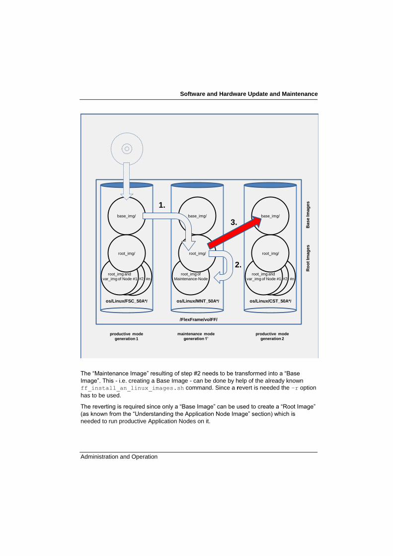
Software and Hardware Update and Maintenance
Administration and Operation 331
1
`
os/Linux/FSC_50A*/
productive mode
generation 1
/FlexFrame/volFF/
Base Im
ag
es
root_img and
var_img of Node #n
root_img and
var_img of Node #2root_img and
var_img of Node #1
base_img/
root_img/
os/Linux/CST_50A*/
root_img and
var_img of Node #n
root_img and
var_img of Node #2root_img and
var_img of Node #1
base_img/
root_img/
os/Linux/MNT_50A*/
root_img of
Maintenance-Node
base_img/
root_img/
maintenance mode
generation 1’
productive mode
generation 2
Ro
ot
Imag
es
1.
2.
3.
The ―Maintenance Image‖ resulting of step #2 needs to be transformed into a ―Base
Image‖. This - i.e. creating a Base Image - can be done by help of the already known
ff_install_an_linux_images.sh command. Since a revert is needed the –r option
has to be used.
The reverting is required since only a ―Base Image‖ can be used to create a ―Root Image‖
(as known from the ―Understanding the Application Node Image‖ section) which is
needed to run productive Application Nodes on it.
Software and Hardware Update and Maintenance
332 Administration and Operation
Based on the maintained Linux Application Node Image (specified by -s option) the
ff_install_an_linux_images.sh command will spawn another Linux Application
Node Image (specified by -t option). You can assign systems to this Linux Application
Node Image by using ff_an_adm.pl and create Nodes by using the ff_new_an.sh
command. All of the Nodes running on it will benefit from the software maintenance you
made. This launch of ff_install_an_linux_images.sh command will copy the
entire ―Root Image‖ to a ―Base Image‖ as known.
Synopsis
ff_install_an_linux_images.sh –r -s <srcdir> -t <trg> \
[-v] [-d] [-i]
Example
(Remember the step #2 asked to shut down the used Application Node)
cn1:/ # cd /FlexFrame/volFF/os/Linux
cn1:/FlexFrame/volFF/os/Linux # ff_install_an_linux_images.sh –r \
-s MNT_5.1A00-001.SLES-10.x86_64/ -t CST_5.0A00-001.SLES-10.x86_64/
Notice that the ff_install_an_linux_images.sh command accepts
relative and absolute path names as arguments to the –s and –t option. You
may save some typing when you first change to the
/FlexFrame/volFF/os/Linux/ directory as shown in the example above.
It is worthwhile using a meaningful prefix for the directory name to keep track of
the images. A good start for choosing the name is to replace the original prefix
(here: MNT_) by CST_ indicating a ―Customer‖ image.
Consult the ff_image_types(8) manual page for a suggestive naming of the
arguments to the -s and -t options.
As mentioned earlier the SLES operating systems, which are used within a FlexFrame
environment, have been changed in a number of places to implement the concepts,
which make FlexFrame unique. In some situations the changes made during
Maintenance (Step #2) may conflict with FlexFrame‘s concepts. In order to keep
FlexFrame going smoothly the FlexFrame implementations have higher priority than the
changes made during Maintenance mode. This means: these changes made during

Software and Hardware Update and Maintenance
Administration and Operation 333
Maintenance mode will be replaced during reverting5. If possible the
ff_install_an_linux_images.sh command will point out to these conflicts:
cn1:/FlexFrame/volFF/os/Linux # ff_install_an_linux_images.sh –r \
-s MNT_5.1A00-001.SLES-10.x86_64/ -t CST_5.0A00-001.SLES-10.x86_64/
...
The following files were modified during maintenance. To ensure
FlexFrame's functionality they will be replaced now by their
FlexFrame specific versions. See "Administration and Operation
Guide" for details:
/etc/issue
/root/.ssh/authorized_keys
/etc/fstab
A copy of the maintenance version is available as
"<file>.maintenance".
...
Here you must compare for example /etc/fstab.maintenance (this is the version of
this file after leaving maintenance and before reverting) and the /etc/fstab (this is the
needed FlexFrame version of this file, installed after revert). You may have to merge
entries from the /etc/fstab.maintenance file into the /etc/fstab file.
Note: it is important to double-check the reverted image whether it contains the expected
changes: This is possible for example by simply comparing the just created ―Base Image‖
with the ―Root Image‖. If there are changes which were replaced by FlexFrame settings it
is needed to decide whether they can be inserted again. Please take notice of section
11.4.8 Maintaining Use Cases.
After reverting the source of the operation the ―Maintenance Image‖ seems to be
needless: it was the source for the revert and can be removed now. But in section 11.4.8
Re-Using the Maintenance Image on page 335 you will see how experienced
administrators might use it again.
11.4.7 Migrating remaining Application Nodes
Now, after testing and reverting the ―Maintenance Image‖ it is time to go productive with
all the Application Nodes.
The created ―Base Image‖ acts as a normal ―Base Image‖ i.e. it can now serve as a
source for other Application Node Images. All Application Nodes inherit the changes from
Maintenance Mode.
5 FlexFrame for SAP Infrastructure Consultants might seek advice in /opt/FlexFrame/lib/an.

Software and Hardware Update and Maintenance
334 Administration and Operation
To do this it is only necessary to use the well known administration commands. Since this
is not ―Maintenance Mode‖ specific – the procedure and all the commands are already
known - now only the example follows:
At first assign the created image to the Application Nodes by help of the ff_an_adm.pl
command and then create an image by help of the ff_new_an.sh command and boot.
Remember we had four Application Nodes in group sles10_x64 of the pp1 pool.
The first one – named pa-rx300-1 – was used for the Maintenance Cycle and is
currently down. Let us start with that node:
cn1:/ # ff_an_adm.pl --op os --ospath Linux/CST_5.1A00-001.SLES-
10.x86_64 \
--name pa-rx300-1
The ff_an_adm.pl command asked for it so let us launch the ff_new_an.sh
command:
cn1:/ # ff_new_an -n pa-rx300-1
Finally boot the Application Node:
cn1:/ # ff_ponpoff.pl --op power-on --name pa-rx300-1
All the other nodes of the pool group – named pa-rx300-2, pa-rx300-3 and pa-
rx300-4 – which are still running on the old image can be handled in a similar way.
Instead of powering them on they just need to be rebooted:
cn1:/ # ff_an_adm.pl --op os --ospath Linux/CST_5.1A00-001.SLES-
10.x86_64 \
--name pa-rx300-2
cn1:/ # ff_new_an -n pa-rx300-2
cn1:/ # ssh pa-rx300-2 init 6
cn1:/ # ff_an_adm.pl --op os --ospath Linux/CST_5.1A00-001.SLES-
10.x86_64 \
--name pa-rx300-3
cn1:/ # ff_new_an -n pa-rx300-3
cn1:/ # ssh pa-rx300-3 init 6
cn1:/ # ff_an_adm.pl --op os --ospath Linux/CST_5.1A00-001.SLES-
10.x86_64 \
--name pa-rx300-4
cn1:/ # ff_new_an -n pa-rx300-4
cn1:/ # ssh pa-rx300-4 init 6

Software and Hardware Update and Maintenance
Administration and Operation 335
You can do this of course in a more efficient way – the code above tries to show the basic
strategy.
The switch to the maintained image costs only a few minutes! In case of problems you
can switch back in the same way.
Please bear in mind: It is very important that all the Linux Application Nodes of
one pool group have the same configuration (software, patches) since each one
must be able to take over if another one fails. That is why all of the Linux
Application Nodes of a pool group must run on the same image.
In the course of time you might get a lot of Application Node Images in
/FlexFrame/volFF/os/Linux/. In order to keep track of their history you might use
the ―.itoc‖ file of the ―Base Image‖.
11.4.8 Re-Using the Maintenance Image
This section describes a time-saving extension to the ―Maintenance Cycle‖. You should
use it not before you have got some experience with the ―Maintenance Cycle‖ itself.
Reverting the ―Maintenance Image‖ as described in section 11.4.6 Step #3: Reverting the
Maintenance Image on page 330 ended with an apparently needless ―Maintenance
Image‖: it was the source of the operation. If you are satisfied with the results of the
Maintenance Cycle i.e. the migrated Application Nodes are running fine you can remove
it indeed.
But why it is not removed automatically?
Because it is possible to configure the Application Node (used to perform the
maintenance tasks) and to boot it from the ―Maintenance Image‖ again: this allows fixing
errors you found while testing the just generated images without starting a new
―Maintenance Cycle‖.
Be aware that only the same Application Node can be used to boot the ―Maintenance Image‖ again. You can use the ff_an_adm.pl command to get the needed information.
Launch it with no option (output trimmed):

Software and Hardware Update and Maintenance
336 Administration and Operation
cn1:/ # ff_an_adm.pl
…
--ospath <path to os image>
The path of the os image to be used.
Currently available os image pathes are:
Linux/CST_5.1A00-001.SLES-10.x86_64
Linux/FSC_5.1A00-001.SLES-11.x86_64
Linux/MNT_5.1A00-001.SLES-10.x86_64 (maintenance only (pa-rx300-
1))
Linux/TST_5.1A00-002.SLES-10.x86_64
…
It reveals the name of the only Application Node that can use this ―Maintenance Image‖:
the pa-rx300-1 node.
To assign the ―Maintenance Image‖ again to this Node use the well known ff_an_adm.pl command:
cn1:/ # ff_an_adm.pl --op os --ospath Linux/MNT_5.1A00-001.SLES-
10.x86_64 \
--name pa-rx300-1
After that create the image for the Application Node:
cn1:/ # ff_new_an.sh –B -n pa-rx300-1
Notice that ff_new_an.sh needs to be called with the ―-B‖ option to only configure boot
information for this node because the image is already configured for this node and
cannot be reconfigured.
Finally, reboot the maintenance node:
cn1:/ # ssh pa-rx300-1 init 6
or switch it on if it is powered off:
cn1:/ # ff_ponpoff.pl --op power-on --name pa-rx300-1
After some time the node will come up running the ―Maintenance Image" and you can
perform further maintenance tasks and fix errors you found while testing.
As soon as you have finished maintaining this image, shut down the node and revert the
―Maintenance Image‖ to a new ―Base Image‖ again as described in section 11.4.6 Step
#3: Reverting the Maintenance Image on page 330. Note that you can not use the same
target directory name for the revert operation (it already exists.) Use a different directory
name or remove the old one if you want to use the same target directory name as before.

Software and Hardware Update and Maintenance
Administration and Operation 337
Now it is possible to have one node for maintaining the Maintanance Image and
another node to test the reverted image in production mode because the
Maintenance and Base Images reside inside two different directory trees.
You will not have to switch one Application Node forth and back between
Maintenance Image and Base Image again and again. You still need to shut
down the maintenance Application Node before reverting to ensure a consistent
image state.
In theory it is also possible to run one Application Node always in ―Maintenance
Mode‖ in order to keep it up to date with security updates and create a Base
Image from it once in a while as needed.
However, it is strongly recommended to remove the Maintance Image once the
maintained Image has been tested intensively in production mode and perform
further maintenance tasks by starting over with a complete new Maintance Cycle
based on the Maintained Images, or in other words: perform the whole 1-2-3
procedure again on the already customized Images.
Following this procedure closely allows keeping all maintained image versions
and rolling back to working images if something failed during a Maintenance
Cycle.
You can keep track of all changes by just looking into the mentioned ―.itoc‖ file
of the ―Base Images‖.
11.4.9 Maintaining Use Cases
We would like to point out that changes due to 3rd party software or patches or
customer modifications may have heavy (negative) side effects to the FlexFrame
functionality.
Installing third party software on Application Nodes may cause functional
restrictions and other malfunctions of the FlexFrame system software. Fujitsu
shall have no liability whatsoever whether of a direct, indirect or consequential
nature with regard to damages caused by the third party software or its
erroneous installation.
Installation of software or other maintaining work as described in this section has
to be done by help of a Maintenance Cycle as described in section 11.4
Maintenance of Application Nodes - Software on page 318. Not following this
procedure i.e. maintain software when running in normal operation may harm the
entire Application Node group. Resulting malfunctions are not an issue of
FlexFrame.

Software and Hardware Update and Maintenance
338 Administration and Operation
11.4.9.1 Service Packs
It is not allowed to install any Service Packs on Application Node images manually. The
only way to obtain a new service pack for Application Nodes is to install new Application
Node images delivered from Fujitsu. Service Packs contain a lot of changes that can
have influences to the FlexFrame functionality. Service Packs can also contain initial
configuration files that will substitute the FlexFrame configurations.
11.4.9.2 Updating/Installing a New Linux Kernel
This section describes how to install an additional (alternative) Linux kernel into an
existing Application Node image.
The netboot configuration /tftpboot/pxelinux.cfg/<hw class>_<pool name>_<image tree name>
will determine which Linux kernel and initial ramdisk need to be used for a subset of
Application Nodes. The image tree name of original images delivered by Fujitsu begins with FSC_ and follows the scheme
FSC_<FF version>.<OS version>.<OS architecture>.
11.4.9.2.1 Software Stage
To install and update any software packages in FlexFrame, it is useful to mount your NAS
system or jukebox or any other software stage on a local mount point at your Control
Node. The same software stage must be mounted on an Application Node which is
appointed to install the new kernel-RPMs during the maintenance cycle.
For example, your software stage on the Control Node is /FlexFrame/volFF/FlexFrame/stage and the new kernel to install is
2.6.16.60-0.63.1.
Create a subdirectory for the delivered software:
control1: # cd /FlexFrame/volFF/FlexFrame/stage
control1:/FlexFrame/volFF/FlexFrame/stage # mkdir -p SLES10/kernel
Copy the delivered software packages to the software stage.
Kernel RPM:
control1: # cp <somewhere>/kernel-smp-2.6.16.60-0.63.1.x86_64.rpm
/FlexFrame/volFF/FlexFrame/stage/SLES10/kernel
Kernel kdump:
control1: # cp <somewhere>/kernel-kdump-2.6.16.60-0.63.1.x86_64.rpm
/FlexFrame/volFF/FlexFrame/stage/SLES10/kernel

Software and Hardware Update and Maintenance
Administration and Operation 339
Kernel source:
control1: # cp <somewhere>/kernel-source-2.6.16.60-0.63.1.x86_64.rpm
/FlexFrame/volFF/FlexFrame/stage/SLES10/kernel
With SLES 10 (Service Pack 1 and later) Novell has introduced the Partner
Linux Driver Process (PLDP). There is no need to download drivers for the
update kernel. The existing drivers are reused for the new kernel.
11.4.9.2.2 Installing a New Linux Kernel
Logon to the appointed Application Node running the maintenance cycle.
Check the currently installed Linux kernels:
pa-rx300-1:/ # rpm -qa | grep kernel
kernel-kdump-2.6.16.60-0.59.1
kernel-smp-2.6.16.60-0.59.1
kernel-source-2.6.16.60-0.59.1
Mount the software stage:
pa-rx300-1: # mkdir /mnt/stage
pa-rx300-1: # mount -t nfs <filer>:/vol/volFF/FlexFrame/stage /mnt/stage
To install the new kernel, execute the following command:
pa-rx300-1: # cd /mnt/stage/SLES10/kernel
pa-rx300-1:/mnt/stage/SLES10/kernel # export YAST_IS_RUNNING=instsys
pa-rx300-1:/mnt/stage/SLES10/kernel # rpm -ihv kernel-smp-2.6.16.60-
0.63.1.x86_64.rpm
pa-rx300-1:/mnt/stage/SLES10/kernel # rpm –ivh kernel-kdump-2.6.16.60-
63.1.x86_64.rpm
pa-rx300-1:/mnt/stage/SLES10/kernel # rpm –ivh kernel-source-2.6.16.60-
63.1.x86_64.rpm
‗YAST_IS_RUNNING=instsys‘ is used to skip updating the bootloader
menu.
11.4.9.2.3 New initrd, Kernel and Netboot Configuration
Before booting the maintained Application Node image, it is necessary to create a new
initrd, install the initrd and kernel in /tftpboot and update the PXE configuration file.
All these steps will be automatically performed on the Control Node by the command:
control1:~ # ff_new_an.sh -B -n pa-rx300-1

Software and Hardware Update and Maintenance
340 Administration and Operation
Internally, this will call the ff_mkinitrd.sh utility, update the storage export
configuration and create a new PXE configuration file.
The latest kernel will be automatically used in the future. If you like to revert to a previous
kernel, follow the instructions described below in Chapter 11.4.9.2.5.
Now reboot the Application Node and verify that it is working properly:
pa-rx300-1:~ # reboot
11.4.9.2.4 Partner Linux Driver Process
The Partner Linux Driver Process (PLDP) replaces the traditional method of driver
provisioning for SLES 10 (Service Pack 1 and later). The most benefit of this process is
the support for reusing existing drivers for errata kernels. There is no need to download
drivers for those kernels.
Nevertheless if updated driver packages are released (e.g. a new version) these
packages can be installed on Control Node or Application Nodes like an ―installable
patch‖.
Depending on a special configuration the document ―Novell Partner Linux Driver Process
for PRIMERGY servers‖ describes the update procedure in detail. This document is
available at URL:
http://ts.fujitsu.com/support/downloads.html
11.4.9.2.5 Switching Between Different Kernels
If you have multiple kernel releases installed in the Application Node image and like to
switch to a different kernel, change the the symlink …/root_img/boot/vmlinuz and
run ff_new_an.sh -B -n <node name> again.
This will change the PXE configuration files for this image and hardware class and will
affect all Application Nodes of the same hardware class using this image.
The initrd does not need to be re-created nor does the initrd-symlink need to be
changed because it always contains all kernel releases found in an image.
11.4.9.3 ServerView Update
The ServerView update comprises the components ―Agents‖ and ―RAID Manager‖ on the
Application Node.
The components for the Application Nodes are the same as for the Control
Nodes.

Software and Hardware Update and Maintenance
Administration and Operation 341
README files or other installation instructions are available in the download
area.
Always use the instructions that come with the downloaded software!
Mount your software stage:
pa-rx300-1:/mnt # mkdir /mnt/stage
pa-rx300-1:/mnt # mount -t nfs <filer>:/vol/volFF/FlexFrame/stage
/mnt/stage
11.4.9.3.1 ServerView Agents
Go to your software stage directory. There you will find the following RPMs: srvmagt-agents-*.i386.rpm
srvmagt-mods_src-*.i386.rpm
srvmagt-eecd-*.i386.rpm
ServerViewConnectorService-*.386.rpm
And the associated installation script: srvmagt.sh.
Upgrade the ServerView Agents by using srvmagt.sh:
pa-rx300-1:~ # cd /mnt/stage
pa-rx300-1:/mnt/stage # sh srvmagt.sh install
11.4.9.3.2 ServerView RAID Manager
Go to your software stage directory. There you will find the
ServerView_RAID-*.i386.rpm RPM.
Upgrade the ServerView RAID Manager by:
pa-rx300-1:~ # cd /mnt/stage
pa-rx300-1:/mnt/stage # rpm -U ServerView_RAID-*.i386.rpm
The ServerView update is now finished.
11.4.9.4 Upgrading the Application Software
The rules for installation of application software (SAP/Oracle) apply here as well.
An Application Node should be available exclusively for upgrading the application
software, so that the physical host name can be set to be identical with the virtual host
name of the application.

Software and Hardware Update and Maintenance
342 Administration and Operation
Provided this has been done, upgrading can be carried out in accordance with the
software vendor's standard guides.
All parts of the application software must reside on the network files system mounted
from the NAS system.
For more details see the SAP Installation Guides.
11.4.9.5 Updating RPM Packages on an Application Node
To update the SLES RPM packages you can use the original Novell tools to perform an
online update.
11.4.9.5.1 Setup a patch server
It is not recommended to connect your FlexFrame environment directly to the Internet to
download patches or updates. Therefore it is advisable to set up an own patch server,
which provides the necessary update packages. See: http://www.novell.com/de-
de/linux/smt/ and http://www.novell.com/communities/files/appnote-2009-12-10-v1_7.pdf
for hints.
Provided that this patch server is accessible for the Application Node in maintenance
mode, a normal online update with YaST can be performed.
11.4.9.5.2 Connect the patch server to the FlexFrame environment
There are several possibilities to connect your local patch server to your FlexFrame
environment. It‘s up to your internal network and security policy, which way is the right
way for you.
Some of them are described in http://www.novell.com/communities/files/appnote-2009-
12-10-v1_7.pdf
It is possible to setup an ‗External Connectivity‘ on the Control Node to connect your
patch server to the FlexFrame environment. On the Application Node in maintenance
mode you have to setup a ‗SSH tunnel‘. Or you can copy the data from your patch server
to an ‗USB disk‘ and connect this disk directly to the Application Node in maintenance
mode. Or copy the data to the local disk of the Control Node or to a directory on the filer
and share (NFS, SMB/CIFS, HTTP(S) or FTP) this directory for the Application Node in
maintenance mode.
11.4.9.5.3 Prepare the Online Update
To prepare the online update you have to define the installation source. That‘s the way,
how you provide the update packages, i.e. your patch server
On an SLES10 Application Node:
YaST Software Installation Source Add Media Type

Software and Hardware Update and Maintenance
Administration and Operation 343
See section 8.3.3 ―Selecting the Installation Source‖ from
http://www.novell.com/documentation/sles10/sles_admin/data/sec_yast2_sw.html#sec_y
ast2_sysconfig_medium for more information.
On an SLES11 Application Node:
YaST Software Software Repositories Add Media Type
See Section 9.3 ―Managing Software Repositories and Services‖
http://www.novell.com/documentation/sles11/book_sle_deployment/data/sec_y2_sw_inst
source.html#sec_y2_sw_instsource for more information.
The Media Type strongly depends on the way you provide the update packages (see
section 11.4.9.5.2 ‖Connect the patch server to the FlexFrame environment‖ on page
342).
11.4.9.5.4 Perform the Online Update
Now you can perform the online update:
YaST Software Online Update
For SLES 10 see section 8.3.5 ―YaST Online Update‖ from
http://www.novell.com/documentation/sles10/sles_admin/data/sec_yast2_sw.html#sec_y
ast2_sysconfig_onupdate for more information.
For SLES11 see section 1.0 ―YaST Online Update‖ from
http://www.novell.com/documentation/sles11/book_sle_admin/data/cha_onlineupdate_yo
u.html#cha_onlineupdate_you for more information.
If the online update has installed a new kernel, it is necessary to create a new
initrd and update the netboot configuration, before you can reboot the
maintained Application Node.
All these steps will be automatically performed on the Control Node by the command:
control1:~ # ff_new_an.sh -B -n pa-rx300-1
Internally, this will call the ff_mkinitrd.sh utility, update the storage export
configuration and create a new PXE configuration file.
11.4.9.6 Updating vmware-open-vm-tools
If an update of the vmware-open-vm-tools is necessary, the needed packages will be part
of the current FlexFrame Service DVD.

Software and Hardware Update and Maintenance
344 Administration and Operation
On this Service DVD in directory ‗vmware/SLES1<x>-SP<y>‘ you will find the following
RPMs:
vmware-open-vm-tools-common-*.x86_64.rpm
vmware-open-vm-tools-nox-*.x86_64.rpm
primergy-vmware-kmp-*.x86_64.rpm
The following example will show the update for an Application Node running SLES10.
On the Control Node create a subdirectory for the delivered software:
control1: # cd /FlexFrame/volFF/FlexFrame/stage
control1:/FlexFrame/volFF/FlexFrame/stage # mkdir -p SLES10/vmware
Copy the delivered software packages to the software stage.
control1: # cp /media/dvd/vmware/SLES10-SP3/*
/FlexFrame/volFF/FlexFrame/stage/SLES10/vmware
Log on to the Application Node in Maintenance and perform an rpm update:
pa-rx300-1:~ # cd /mnt/stage/SLES10/vmware/
pa-rx300-1:/mnt/stage/SLES10/vmware # rpm –Uhv primergy-vmware-kmp-
*.x86_64.rpm vmware-open-vm-tools-common-*.x86_64.rpm vmware-open-vm-
tools-nox-*.x86_64.rpm
After installing the vmware KMP package, it is necessary to create a new initrd
before you can use the image for a virtual Application Node.
All these steps will be automatically performed on the Control Node by the command:
control1:~ # ff_new_an.sh -B -n pa-rx300-1
Internally, this will call the ff_mkinitrd.sh utility, to build a new initrd file with correct
linkage for the vmware drivers.
11.4.9.7 Upgrading the Application Software
The rules for installation of application software (SAP/Oracle) apply here as well.
An Application Node should be available exclusively for upgrading the application
software, so that the physical host name can be set to be identical with the virtual host
name of the application.

Software and Hardware Update and Maintenance
Administration and Operation 345
Provided this has been done, upgrading can be carried out in accordance with the
software vendor's standard guides.
All parts of the application software must reside on the network files system mounted
from the NAS system.
For more details see the SAP Installation Guides.
11.4.9.8 Updating RPM Packages on an Application Node
To update the SLES RPM packages you can use the original Novell tools to perform an
online update.
11.4.9.8.1 Setup a patch server
It is not recommended to connect your FlexFrame environment directly to the Internet to
download patches or updates. Therefore it is advisable to set up an own patch server,
which provides the necessary update packages. See: http://www.novell.com/de-
de/linux/smt/ and http://www.novell.com/communities/files/appnote-2009-12-10-v1_7.pdf
for hints.
Provided that this patch server is accessible for the Application Node in maintenance
mode, a normal online update with YaST can be performed.
11.4.9.8.2 Connect the patch server to the FlexFrame environment
There are several possibilities to connect your local patch server to your FlexFrame
environment. It‘s up to your internal network and security policy, which way is the right
way for you.
Some of them are described in http://www.novell.com/communities/files/appnote-2009-
12-10-v1_7.pdf
It is possible to setup an ‗External Connectivity‘ on the Control Node to connect your
patch server to the FlexFrame environment. On the Application Node in maintenance
mode you have to setup a ‗SSH tunnel‘. Or you can copy the data from your patch server
to an ‗USB disk‘ and connect this disk directly to the Application Node in maintenance
mode. Or copy the data to the local disk of the Control Node or to a directory on the filer
and share (NFS, SMB/CIFS, HTTP(S) or FTP) this directory for the Application Node in
maintenance mode.
11.4.9.8.3 Prepare the Online Update
To prepare the online update you have to define the installation source. That‘s the way,
how you provide the update packages, i.e. your patch server
On an SLES10 Application Node:
YaST Software Installation Source Add Media Type

Software and Hardware Update and Maintenance
346 Administration and Operation
See section 8.3.3 ―Selecting the Installation Source‖ from
http://www.novell.com/documentation/sles10/sles_admin/data/sec_yast2_sw.html#sec_y
ast2_sysconfig_medium for more information.
On an SLES11 Application Node:
YaST Software Software Repositories Add Media Type
See Section 9.3 ―Managing Software Repositories and Services‖
http://www.novell.com/documentation/sles11/book_sle_deployment/data/sec_y2_sw_inst
source.html#sec_y2_sw_instsource for more information.
The Media Type strongly depends on the way you provide the update packages (see
section 11.4.9.8.2 ‖Connect the patch server to the FlexFrame environment‖ on page 1).
11.4.9.8.4 Perform the Online Update
Now you can perform the online update:
YaST Software Online Update
For SLES 10 see section 8.3.5 ―YaST Online Update‖ from
http://www.novell.com/documentation/sles10/sles_admin/data/sec_yast2_sw.html#sec_y
ast2_sysconfig_onupdate for more information.
For SLES11 see section 1.0 ―YaST Online Update‖ from
http://www.novell.com/documentation/sles11/book_sle_admin/data/cha_onlineupdate_yo
u.html#cha_onlineupdate_you for more information.
If the online update has installed a new kernel, it is necessary to create a new
initrd and update the netboot configuration, before you can reboot the
maintained Application Node.
All these steps will be automatically performed on the Control Node by the command:
control1:~ # ff_new_an.sh -B -n pa-rx300-1
Internally, this will call the ff_mkinitrd.sh utility, update the storage export
configuration and create a new PXE configuration file.
11.4.9.6 Updating vmware-tools
To update the vmware-tools to a newer version, we recommend to use our provided
Application Node Images containing this new version of vmware-tools.
To install a newer version of vmware-tools during a FlexFrame maintenance cycle please
refer to the OSP documentation of VMware, which can be found at
http://packages.vmware.com

Software and Hardware Update and Maintenance
Administration and Operation 347
Installation of vmware-tools from an ESXi host is not permitted.
Log on to the Application Node in Maintenance, copy the downloaded vmware-tools
packages to this Application Node and follow the instructions to install the vmware-tools
on SLES11 or SLES10 as described in the VMware OSP documentation mentioned
above.
11.5 Maintenance of the Application Nodes - Hardware
11.5.1 Changing BIOS Settings for Netboot
For detailed information on setting BIOS parameters refer to the hardware
documentation. Look at some of the configuration examples below. The exact procedure
may differ depending on the BIOS version of your hardware. For newer server models
refer to the corresponding documentation called HW Characteristics (HW-Steckbrief) – in
these documents (delivered with the Service CD of a FlexFrame for SAP version and also
on the FTS Extranet on https://partners.ts.fujitsu.com/com/service/ps/Software/flexframe)
the server specific properties relevant for installing the server within a FlexFrame for SAP
environment are collected.
11.5.2 Replacing a Network Card – Application Node
There are two cases for replacing a network card on an Application Node:
The card has failed and you want to replace it by a card of same type.
The network card is replaced by a card of another technology, e.g. 1GBit to 10GBit
migration or vice versa.
If a network card on an Application Node fails and is replaced, further actions are
necessary to ensure proper operation.
During their boot processes, PRIMERGY nodes need to retrieve some information
through lower level protocols which are based on hardware addresses (MAC addresses).
The PRIMERGY's BIOS utilizes DHCP for that purpose.
The MAC address is the built-in, physical address which is unique to that network card.
Since there are two network cards configured for booting you may not even notice the
MAC address change of a single one, because the other card will be used for booting.
Once the server is up, operation is normal. For full redundancy – even for booting – we
recommend to adjust the configuration accordingly.

Software and Hardware Update and Maintenance
348 Administration and Operation
On PRIMERGY blade systems, use the management blade to determine the server
blade MAC addresses.
On PRIMERGY non-blade systems, use BIOS or network card labels to determine
the MAC addresses.
To change the MAC addresses for booting, use the command below. Replace the node
name and MAC addresses of the sample with your Application Node's name and noted
addresses:
control:~ # ff_an_adm.pl --op mac --name appnode5
--mac 00:e0:00:c5:19:41,00:e0:00:c5:19:41
MAC addresses changed.
The program changed the MAC addresses of the node within DHCP configuration and
LDAP. No further intervention is necessary.
Some software licenses are derived from information based on server specific
numbers, such as MAC addresses of network cards. On Linux, double-check
your SAP licenses after you have replaced a network card.
If a network card on an Application Node is replaced for technology change reasons the
following steps are necessary:
1. Remove the Application Node from the FlexFrame landscape with ff_an_adm.pl --op rem
2. Remove the 1GB network cables of the Application Node
3. Remove the 1GB NIC cards from the Application Node
4. Plug in the 10GB NIC cards into the Application Node
5. (see corresponding HW-Characteristics Quickguide)
6. Install the Application Node with ff_an_adm.pl
(for details see the corresponding HW-Characteristic Quickguide)
Example:
ff_an_adm.pl --op add --name sno2rx1 --type RX600S4 --pool
pool2 --group default ---swgroup 1 --ospath Linux/FSC_5.1A00-
005.SLES-11.x86_64 --host 25 --mac
00:1b:21:24:4f:5d,00:1b:21:24:4f:5c -–10gbit
7. Plug in the network cables according to the wiring output given by ff_an_adm.pl
8. Call ff_new_an.sh to generate an image for the new Application Node
9. Boot the Application Node

Software and Hardware Update and Maintenance
Administration and Operation 349
11.5.3 Replacing a Switch Blade
There are two cases for replacing a switch blade:
In case of an HW error you have to replace one switch blade.
You can change the type of the used switch blade. In this case you have to replace
both switch blades.
In the first case (HW error) perform the following actions:
1. You have to replace the switch blade as described in the HW description of the
BX Server.
2. Create the configuration file for the switch blade with the function ff_bx_cabinet.pl –-op swb-config. See chapter 7.7.7 Getting Switch Blade
Configuration for a detailed description of the function.
3. Upload configuration to switch as displayed by ff_bx_cabinet.pl –-op swb-
config.
In the second case (change the type) perform the following actions:
1. Deactivate the usage of each server blade.
2. Remove the network cables from the switches.
3. Replace both switches.
4. Plug in the network cables.
5. Call ff_bx_cabinet_adm.pl --op swb-change to update LDAP Database.
6. Create the configuration file for the switch blade with the function
ff_bx_cabinet.pl –-op swb-config. See chapter 7.7.7 Getting Switch Blade
Configuration for a detailed description of the function.
7. Upload configuration to switch as displayed by ff_bx_cabinet.pl –-op swb-
config.
8. Now you can use the server blades again.
11.5.4 Replacing Power Control Hardware
This section describes what to do after the replacement of power control hardware,
depending on your Application Nodes and Control Nodes hardware.
For instructions on replacing the power control hardware, please refer to the
documentation delivered with your hardware.
Software and Hardware Update and Maintenance
350 Administration and Operation
11.6 Maintenance of ESXi Servers
11.6.1 BIOS Updates
To update the BIOS of a PRIMERGY server that is used as an ESXi server, use the
standard BIOS update procedure for PRIMERGY servers based on a bootable USB
memory stick. Please note that the method using ASPs (Autonomous Primergy Support
Packages) is not applicable in this case.
11.6.2 Replacing a Network Card - ESXi Server
If a network card of an ESXi server fails and is replaced, further actions are necessary to
ensure proper operation.
PRIMERGY servers used as ESXi servers in FlexFrame get the address used for ESXi
management from a DHCP server running on the FlexFrame Control Center. The DHCP
server determines the correct IP address based on the requester's MAC address.
The MAC address is the built-in, physical address which is unique to that network card.
As the MAC address is changed after replacing a network card, we recommend adjusting
the configuration accordingly,
● On PRIMERGY blade systems, use the management blade to determine the server
blade MAC addresses.
● On PRIMERGY non-blade systems, use BIOS or network card labels to determine
the MAC addresses.
To change the MAC addresses for DHCP, use the command below. Replace the node
name and MAC addresses of the sample with your ESXi server's name and noted
addresses:
control:~ # ff_esx_adm.pl --op mac --name esxnode5
--mac 00:e0:00:c5:19:41,00:e0:00:c5:19:42
The program changes the MAC addresses of the node within DHCP configuration and
LDAP. No further intervention is necessary.
11.6.3 ESXi Updates and Patches
VMware provides patches and updates for ESXi servers. While updates are for
maintenance releases, patches address critical security fixes or urgent bug fixes. An
update or patch can include a new build of firmware, an update of VMware Tools, or an
update of the vSphere Client.
Please note that patches and updates of VMware Tools cannot be applied using the
standard VMware procedures. The FlexFrame Application Node images contain the

Software and Hardware Update and Maintenance
Administration and Operation 351
VMware Tools operating system specific packages (OSPs). For a description on how to
upgrade these tools refer to section 11.4.9.6 on page 343.
VMware provides several tools for installing updates and patches to ESXi hosts:
● esxcli - command-line utility
● vCenter Update Manager - automates patching and updates
The esxcli utility is part of the vSphere CLI, which is available on the FlexFrame Control
Nodes.
For more information on these tools as well as further usage hints and recommendations
please refer to the appropriate VMware documentation.
11.7 Maintenance of Other FlexFrame Components
11.7.1 NetApp Storage
ONTAP Patches
Before applying a new patch to the Filer's ONTAP make sure that it is supported for the
FlexFrame concept. In doubt contact the Fujitsu support.
Download the tar file(s) for the new ONTAP onto one of your Control Nodes.
Create a temporary directory e.g. in /FlexFrame/volFF/FlexFrame/stage/ontap
(create the directory if it does not exists) and extract the tar file there.
Proceed as described in the manual or README information of that patch.
Before you activate the new patch by rebooting the Filer, make sure that no SAP system
or Database is busy. You do not need to reboot the Application Nodes, however we
recommend double-checking the mount points after the Filer is up again. If an Application
Node should get stuck, reboot it.
11.7.2 EMC Storage
DART Patches for Celerra Data Movers
Download the patch (default name nas.exe) into the directory /nas/dos/bin on the
Celerra. If you choose the default name nas.exe for your patch, you have to do nothing.
If you take a different name for it, you will have to modify the files
/nas/dos/slot_<ID>/boot.bat with this name, where ID is the data mover ID,
e.g., 2 for server_2 or 3 for server_3.

Software and Hardware Update and Maintenance
352 Administration and Operation
Then you have to reboot all affected data movers by the reboot command on the
Celerra control station:
server_cpu ALL –reboot now
server_version ALL (to see, if the new patched OS version is
active).
Before activating the new patch by rebooting the data movers, make sure that no SAP
system or database is busy. You do not need to reboot the Application Nodes, however
we recommend double-checking the mount points after the data movers are up again. If
an Application Node should get stuck, reboot it.
11.7.3 Cisco Switches and Switch Blades
11.7.3.1 Firmware Update
It may be possible that an update of the switch firmware is necessary. For Cisco Switches
you find a detailed description in the corresponding Cisco software configuration guides
at http://www.cisco.com. For Switch Blades have a look at the corresponding user
manual.
11.7.3.2 Backup of Switch Configurations
The switch configuration may be different to that at the time of installation due to the
operation of a FlexFrame landscape. New Application Nodes and switches may be
added, ports configured and so on. For system backup, there are a lot of well known
products and programs.
To simplify backing up the configuration of all switches used within the FlexFrame landscape the program /opt/FlexFrame/bin/ff_save_switch_config.pl should
be used. It is designed to be run by cron(8) and recommended to call it once a day.
The program is able to backup all LDAP registered switches and switch blades or the
switch or switch blade given by --name. The program connects to a switch or switch
blade and copies the running or startup configuration via TFTP to a Control Node into /tftpboot/<switch name>.config (if --multi is used to
/tftpboot/saved_switchconfigs/<switch host name>.config.YYY-MM-DD).
Synopsis
ff_save_switch_config.pl [--silent] [--running]
[--name <switch name>]
[--ip <control node ip>]
[--multi] [--max_versions <count>]

Software and Hardware Update and Maintenance
Administration and Operation 353
Options
--silent
The silent mode suppresses any message, even error messages.
--running
In normal case the configuration, which the switch reads on booting, is backed up, the so called startup-config. Using the --running option the current running switch
configuration is used instead of startup-config. For a BX600 switch blade of type
1GbE-10/6-Q (has six external ports) the running switch configuration is backed up
only.
--name <switch name>
Backup only the switch with given name. Keep in mind to use the name known at
LDAP database. It may differ from current switch name if it was not synchronized.
--ip <control node ip>
Use control node with given control lan ip address to save configurations to. In
normal case the program is able to detect the control node with running netboot_srv
service itself. If it is not able to detect the active node or cannot determine the
control lan ip of the control node control, the program requests to use the --ip
option.
--multi
Add a date string (ISO 8601 date format) to configuration file names to store more
than one configuration file of a switch. The files are stored in /tftpboot/saved_switchconfigs.
--max_versions <count>
This option is only used with option --multi and restricts the count of saved switch
configuration files to the latest <count> versions. Count defaults to: 10
11.7.3.3 Restore of Switch Configurations
To restore a backed-up switch configuration clear the actual configuration on the switch
then use copy and paste for the switch config commands. Don‘t forget to copy the
restored new running switch configuration on the switch as startup-configuration for the
next reboot.
Be aware, the backed-up switch configuration may not be the last effective
switch configuration because of changes applied after backup.

Software and Hardware Update and Maintenance
354 Administration and Operation
You can get an actual configuration according to LDAP
for switch blades using
ff_bx_cabinet_adm.pl --op swb-config ... (see 7.7.7)
for switch groups using
ff_swgroup_adm.pl --op gen-config ... (see 9.4)
11.7.4 DNS Servers
If the customer wants to change IP addresses of his DNS servers he also has to change
the corresponding FlexFrame configurations:
The DNS servers of each pool can be modified with the command ff_pool_adm.pl (see
4.5).
The DNS servers of the Control Center can be modified by editing the ―forwarders‖ in
the file /etc/named.conf . Originally the DNS Servers of the Control Center came into
FlexFrame by specifying them in the ―Miscellaneous Control Center Settings‖ in the
Management Tool.
Any other DNS server (e.g. explicitly indicated DNS servers in hardware configuration
files), which manually has been entered by the customer, is not under FlexFrame control
and it is the customers responsibility to modify these addresses at the right place.
11.7.5 Third Party Products
If the customer needs to install third party software on the Application Nodes, the maintenance procedures described in this manual must be followed. Installation of
software or patches may have to be performed again after installing a maintenance
image shipped by Fujitsu.
If you have installed additional 3rd
party software to your FlexFrame landscape,
please make sure to back up this software components and their configuration
data for later restore. Please consider: If you install a new FlexFrame image, the
whole file system and directories are overwritten by a complete new root file
system image. Afterwards, any 3rd
party software and configurations have to be
re-installed or restored.
Installing third party software on Control Nodes or Application Nodes may cause
functional restrictions and other malfunctions of the FlexFrame system software.
Fujitsu shall have no liability whatsoever whether of a direct, indirect or
consequential nature with regard to damages caused by the third party software
or its erroneous installation.

Software and Hardware Update and Maintenance
Administration and Operation 355
11.8 MyAMC Agents
For information on the MyAMC Agents please refer to the "myAMC.FA_Agents -
Installation and Administration" manual, chapter 2 "First Steps". Here you will find
detailed information on installation requirements, installation, configuration, the FA web
interface and the domain manager.
11.9 Project specific changes
As mentioned in chapter 2 ―FlexFrame Architecture‖ the FlexFrame solution consists of
both hardware and software. Most of the components are seen as an appliance: they
have well defined purposes and must work together in order to achieve a smoothly
running FlexFrame landscape. Normally only a well defined set of software and hardware
(see section 2.2 ―Hardware and Software‖) is allowed.
However there might be the need to change or modify components, or configuration
details in order to satisfy project specific requirements.
These special changes – project specific changes - mean that your configuration is
outside the FlexFrame standards and lead to a project specific FlexFrame.
These project specific changes may affect the operation of the entire FlexFrame
landscape. An example: Consider you run a SFG (‗Request for Special Release‘) for a
server which is unsupported in standard FlexFrame landscapes. Additionally you
changed some configuration in order to use some nice features of this server. Everything
runs fine. But: You have always to remember these changes. You have to tell the support
team (or other professionals working on this FlexFrame) about this. Without knowing
these project specific modifications a patch installation or upgrade installation may fail or
lead to unsatisfying results.
In order to keep track of these project specific changes a ―Project Activities
Communication Interface‖ has been established. It creates a communication channel
from human beings to human beings (and to FlexFrame commands).
The most important command of this interface is ff_projectinfo.sh which will be
introduced in the following chapter.
11.9.1 The ff_projectinfo.sh command
Name
ff_projectinfo.sh - add entry to projectinfo database file
Synopsis
ff_projectinfo.sh -n <name> \
-t <text> | -r <text file> \

Software and Hardware Update and Maintenance
356 Administration and Operation
[-c <customer specific SFG#> ] \
[-s <severity> ] \
[-C ] \
[-v] [-d]
-n: (name)identify yourself (email address preferred).
Mandatory!
-t: (text) Text to be added (if it is a short one)
-r: (read text file) Text to be added will be read out of
this file
-c: (custom) If a custom specific Special Release
(Sonderfreigabe) has been applied this option has to
name the SFG number
-s: (severity) classification of project specific change
where severity = ‗info‘ or ‗warning‘ or ‗error‘
-C: (CLEAR) change state of projectinfo database file to
READ
-v: (verbose)
-d: (debug)
Description
This script and the projectinfo database file are for use by FlexFrame certified
personnel only.
The objective of the project activities interface is to store and share information about
project specific activities at the FlexFrame landscape.
The ff_projectinfo.sh command is part of the project activities interface for the
FlexFrame solution. It helps to establish a reliable communication between the
professionals. This interface comprises
· this ff_projectinfo.sh command
· the FlexFrame projectinfo database file
· the ff_projectinfo_detector.sh
The ff_projectinfo.sh command serves as the only interface that creates or fills the
FlexFrame projectinfo database file.

Software and Hardware Update and Maintenance
Administration and Operation 357
Options
-n <name>
This option is mandatory: you need to identify yourself. The preferred argument is your
email address. If you want to use a name containing spaces you have to embed it into a
pair of double quotes.
-t <text>
Choose this option if the information you want to add is a short one and can be typed in
the command line. You will have to embed the text into a pair of double quotes (if it is not
only a single word which seems unlikely). For longer texts use the -r option. But: Usage
of either -t or -r option is mandatory.
-r <text file>
Choose this option if you want to add information you prepared previously, or which is
simply too long to be used at command line with the -t option. But: Usage of either -t or
-r option is mandatory. Note: You can add any text you like as long as file(1)
recognizes it as "text". Do not try to add core, dump, tar, files etc.
-c <custom specific Special Release number>
If a custom specific Special Release (Sonderfreigabe) has been applied to the system
this option is mandatory. It has to name the SFG number which you find in the Special
Release documents. It has typically a SFG-20??-??? appearance.
-s <severity>
This option is dedicated to classify the information you add: It helps the professionals
working later on the system to understand the significance resp. severity. The severity
option accepts the following values: info or warning or error. Without giving an explicit
severity a severity of info will be assumed.
-C
This option clears the default unread state of the projectinfo database file i.e. it sets
the state of the projectinfo database file to read.
Explanation: The projectinfo database file can have two states: unread or read.
Each appending of information (i.e. each successful call of the ff_projectinfo.sh
command without the -C option) will set the status to unread. This signals the
professionals the necessity to read it. Note: A FlexFrame with an unread projectinfo
database file is not entitled for an upgrade installation. Use the -C option not until you run
the FlexFrame upgrade. For details see ff_project_detector.sh(8) and the
―FlexFrame for SAP Upgrade Guide‖. This state of read will remain for a limited period
only.
-v
The command will give some more detailed information during its work.

Software and Hardware Update and Maintenance
358 Administration and Operation
-d
The command will write detailed debug information into FlexFrame's default debug files.
More details and comprehensive use cases are available in the online manual pages of ff_projectinfo.sh and ff_project_detector.sh.

Troubleshooting
Administration and Operation 359
12 Troubleshooting
12.1 Locking of Flex Frame Administration Commands
FlexFrame administrative commands stored at /opt/FlexFrame/bin use a resource
locking mechanism to prevent data corruption.
The implementation on the control nodes uses lock files on a shared file system mounted
from the common NAS. Each lock file represents a resource access. Each administrative
command uses typically only a single lock at a time to prevent deadlocks. The lock files
contain information about:
the locking user,
the executing host and the process id,
the timeout set,
the date and time of day when the lock expires,
the name and command line arguments of the locking process.
If a command tries to set a lock which is already set the command will retry to set the lock
for five times with a delay of one second. If the lock could not be set the command will
abort with a notice to user.
To get a robust locking mechanism locks will be removed if a timeout of 300 seconds was
reached AND the locking process no longer exists. If the locking process is still running,
an error message will be displayed by newly called program. The error message and the
exit code define the type or error as shown below.
These locking conditions get detected:
Exit Code Condition Description
0 normal
operation
All fine, locking works as expected. No resource collision with
other processes.
2 normal
operation
There is already a lock and the timeout is not reached.
3 Error IO error setting or unsetting a lock. This should not happen and
points to hanging mounts or filled up filesystems.

Troubleshooting
360 Administration and Operation
Exit Code Condition Description
4 Error Lock set, timeout reached but locking process is still alive. May
be the locking process hangs. Only an administrator is able to
decide if locking process works or hangs. An administrator may
have to clear the lock manually
5 Error Lock set but lock file is empty, therefore no further checks are
possible. This should not happen as FlexFrame locking writes
data to lock files. An administrator has to clear the lock
manually.
Manual administration is necessary for all three error conditions. The administrator has to
check for source of trouble and resolve it. Some examples:
Resource File path
LDAP /FlexFrame/volFF/FlexFrame/locks/\
ldap_lock
ff_new_an.sh /FlexFrame/volFF/FlexFrame/locks/\
ff_new_an.sh_lock
ff_install_an_linux_images.sh /FlexFrame/volFF/FlexFrame/locks/\
ff_install_an_linux_images.sh_lock
The content of the lock files:
User: <login name>
Pid: <id of locking process>
Host: <node name where locking process lives>
Timeout: <time set in seconds> (lock valid till <date and time>)
<command line of locking process>
12.2 Script Logging in FlexFrame
All CN scripts in /opt/FlexFrame/bin log into one file, which is
/var/log/FlexFrame/log_(TIMESTAMP) by default, e.g.
/var/log/FlexFrame/log_2010_05_31. This file is changed daily.
Messages with priority greater than DEBUG (i.e. INFO, WARN and ERROR) are written
into this logfile.

Troubleshooting
Administration and Operation 361
All CN scripts in /opt/FlexFrame/bin debug (if called with option DEBUG) into one
file, which is /var/log/FlexFrame/debug_(TIMESTAMP) by default, e.g.
/var/log/FlexFrame/debug_2010_05_31 . This file is changed daily.
All messages are written into this debug file.
To get further debug information, all Perl scripts can be called with option –debug, as
well as some Shell scripts can be called with option –d .
Exception : The installation scripts ff_init_conf.pl, ff_post_conf.sh and
ff_slapd_init.sh log/debug to /opt/FlexFrame/init_conf/.
ff_nas_ha.pl has its own logging as described in Chap. 8.1.16.
A log entry contains timestamp, priority, username, process ID, hostname, script name
and message text. It looks like this:
2009-04-22 12:29:52 INFO [root,9061,jer1cn1] ff_pool_adm.pl.sh
log example
Two configuration files, log4sh.conf and log4perl.conf reside under
/opt/FlexFrame/etc/.
The destination for Logging/Debugging can be changed in these configuration files by
modifying the corresponding filename lines.
You have to change the destination filenames in both configuration files.
Example:
If you want all scripts (excluding the exceptions) to log into /FlexFrame/volFF/FlexFrame/log_(TIMESTAMP) you have to change
log4perl.appender.LogFileApp.filename=/var/log/FlexFrame/log
to
log4perl.appender.LogFileApp.filename=/FlexFrame/volFF/FlexFrame/l
og
in log4perl.conf
and
log4sh.appender.A1.File = '/var/log/FlexFrame/log'
to
log4sh.appender.A1.File = '/FlexFrame/volFF/FlexFrame/log'
in log4sh.conf

Troubleshooting
362 Administration and Operation
Attention:
The directory of the log-/debugfiles (in the example above
/FlexFrame/volFF/FlexFrame) has to exist.
The user is responsible for the backup/delete of older logfiles.
12.3 Log Files
The default location for logging information of the FlexFrame scripts is
/var/log/FlexFrame on the Control Nodes.
Additional information can be found under /var/log/FlexFrame/tmp .
For easy gathering of log file information on all Application Nodes in FlexFrame, it is not
necessary to login on each Application Node because all log files are directly readable at
the Control Nodes on the mounted NAS system.
To elevate the admin to read these log files it is useful to create symbolic links on the
Control Nodes in the directory /var like this:
control1:/ # cd /var
control1:/var # ls -ld log*
drwxr-xr-x 20 root root 1440 May 2 14:01 log
lrwxrwxrwx 1 root root 58 Apr 29 17:28
log_pool1_klinge1 -> /FlexFrame/volFF/os/Linux/FSC_4.2A00-000.SLES-
9.X86_64/var_img/var-ac10020e/log
lrwxrwxrwx 1 root root 58 Apr 29 17:29
log_pool1_klinge2 -> /FlexFrame/volFF/os/Linux/FSC_4.2A00-000.SLES-
9.X86_64/var_img/var-ac10020f/log
lrwxrwxrwx 1 root root 58 Apr 29 17:30
log_pool1_klinge3 -> /FlexFrame/volFF/os/Linux/FSC_4.2A00-000.SLES-
9.X86_64/var_img/var-ac100210/log
lrwxrwxrwx 1 root root 58 Apr 29 17:30
log_pool1_klinge4 -> /FlexFrame/volFF/os/Linux/FSC_4.2A00-000.SLES-
9.X86_64/var_img/var-ac100211/log
lrwxrwxrwx 1 root root 58 Apr 29 17:30
log_pool1_klinge5 -> /FlexFrame/volFF/os/Linux/FSC_4.2A00-000.SLES-
9.X86_64/var_img/var-ac100212/log
lrwxrwxrwx 1 root root 58 Apr 29 17:31 log_otto_RX300-
01 -> /FlexFrame/volFF/os/Linux/FSC_4.2A00-000.SLES-
9.X86_64/var_img/var-ac100113/log
lrwxrwxrwx 1 root root 58 Apr 29 17:33 log_otto_RX300-
02 -> /FlexFrame/volFF/os/Linux/FSC_4.2A00-000.SLES-
9.X86_64/var_img/var-ac100114/log
control1:/var #

Troubleshooting
Administration and Operation 363
To read the /var/log/messsages from Application Node klinge5 in pool pool1
invoke this:
control1:/ # cd /var
control1:/var # less log_pool1_klinge5/messages
Or enter the log directory from this Application node and look for log files:
control1:/ # cd /var/log_pool1_klinge5
control1:/var/log_pool1_klinge5 # ls -lrt|tail
-rw-r--r-- 1 root root 278 May 4 16:23 log.scagt
-rw-r--r-- 1 root root 174 May 4 16:24 log.vvagt
-rw-r--r-- 1 root root 257 May 4 16:24 log.statusagt
-rw-r--r-- 1 root root 612 May 4 16:28 ntp
-rw-r--r-- 1 root root 5542 May 4 16:35 warn
-rw-r--r-- 1 root root 1696 May 4 16:35 auth.log
-rw-r--r-- 1 root root 484 May 4 18:16 log.busagt
drwxr-xr-x 2 root root 4096 May 4 18:19 sa
-rw-r--r-- 1 root root 27622 May 4 18:19 messages
prw------- 1 root root 0 May 4 18:24 psadfifo
12.4 Network Errors
In most cases, network problems are most times configuration mistakes. All switches are
configured to send SNMP traps and log via syslog to Control Nodes. To see what happened, look at the Control Nodes' /var/log/messages. Any conditions reported by
the switches can be found here. For SNMP traps look at the FA Agents support
database. The FA Agents collect all kinds of SNMP traps for the entire FlexFrame
environment.
12.5 NFS Mount Messages
During start/stop procedures of SAP instances, NFS mount failures for /usr/sap/SYS
and /oracle/db_sw can be seen in /var/log/messages. These messages are not
FlexFrame-specific failures, but may occur on any system that has /usr/sap and
/oracle in its automount maps. These messages are caused by the way SAP is linking
binaries during software development process.
12.6 LDAP Error Codes and Messages
LDAP failures may have various reasons. To determine the reason, first have a look at
the Control Node's /var/log/messages. If slapd does not report anything you may
have to increment the log level configured with /etc/openldap/slapd.conf. Log
levels are additive, and available levels are:

Troubleshooting
364 Administration and Operation
Log level Meaning
1 Trace function calls
2 Debug packet handling
4 Heavy trace debugging
8 Connection management
16 Print out packets sent and received
32 Search filter processing
64 Configuration file processing
128 Access control list processing
256 Stats log connections/operations/results
512 Stats log entries sent
1024 Print communication with shell backends
2048 Entry parsing
Most LDAP problems are related to access control and connection management.
If you have changed the log level send a -HUP to the slapd to advice it to reread
configuration files (use pkill -HUP slapd).
Another reason may be the LDAP client configuration. Check the following issues:
Does the client use the correct server address?
Look at the client messages file to get this information.
If ldapsearch -x on Linux and works properly the problem may be the nsswitch
configuration. These are the top most problems.

Troubleshooting
Administration and Operation 365
When reporting problems with the administration scripts, please provide the
following information:
The error message of the admin tool
A dump of the LDAP database (ldapsearch -x > <file name>)
The configuration files /etc/openldap/slapd.conf and
/FlexFrame/volFF/FlexFrame/ldap/common/slapd.acl.conf
12.7 LDAP and Cache Coherence
While using command scripts to administer your FlexFrame environment, it is possible
that you do not see the changes on Application Nodes immediately. The reason is the
usage of a cache daemon (nscd) which refreshes the cache content in defined time
periods.
There are different caches for different types (e.g. passwd, group, etc.) The configuration of the cache properties is done in /etc/nscd.conf (default). Normally you must not
change the FlexFrame default configuration. Please ask professional service collegues
before doing any change.
You can display your current configuration with nscd –g.
For further information see the corresponding manpages (nscd, nscd.conf).
12.7.1 Linux
To force the refresh of the cache content use nscd –i or nscd restart.
12.8 Start/Stop Script Errors
While executing the SAP service start/stop scripts, several errors may occur for arbitrary
reasons. The messages are grouped by the severity of the message.
The scripts write three types of logs (/FlexFrame/script/logs)
sapservice.log
The log is always available and logs the requests. It contains only the requested
command and the exit state of the request
sap<type>_<SID>_<action>.log
That log contains the messages also written to STDOUT/STDERR
sapservice.<nnn>.debug.<SID>.<type>.<instnr>.action>
That log is only written if option -d is set. It contains a detailed logging of the course
of actions.
The message text below uses ‗%%‘ to indicate there will be a variable output in the
message. There are up to four varying strings in a message.

Troubleshooting
366 Administration and Operation
If you are creating a debug file you are requested to delete debug files by yourself. Otherwise they resist in /FlexFrame/script/log forever.
12.8.1 Severity ‘INFO’
Messages from severity ‗INFO‘ should show the progress of a request and they are always written to STDOUT and to the debug file if option -d is set.
12.8.2 Severity ‘WARN’
Messages from severity ‗WARN should give you a hint to possible configuration errors.
They are always written to STDOUT and to the debug file if option -d is set.
Most of the WARN messages are not critical but you should check if such a message is
displayed.
12.8.3 Severity ‘ERROR’
Messages from severity ‗ERROR‘ are always written to STDOUT and to the debug file if
option -d is set. You have to check it and resolve the issue which leads to the error
message. With opcode ‗cleanup‘ sometimes messages with severity ‗ERROR‘ are shown
but can be ignored.
12.8.4 Severity 'DEBUG'
Debug messages are only printed to the debug file if option -d is used. Those message
are only written to support diagnostics.
12.9 Script Debugging
12.9.1 Shell Scripts
For many FlexFrame scripts, debugging is activated by default. If debugging is not active,
it can be activated with the option –d:
ff_netscan.sh -d
The default location for the debug log file is /var/log/FlexFrame
Further on, shell scripts can be traced using the option -x.
For details, see the man page of the shell in use (man sh; man bash; etc.)
sh -x ff_netscan.sh

Troubleshooting
Administration and Operation 367
12.9.2 Perl Scripts
Before debugging, activate the logging functions of the shell by calling script (For
details, see man script).
The debugger is called using
perl -d <script_name>
Functions:
h
Help
x <expression>
Evaluate an expression (hash/array) and display the result
p <string>
Returns strings
s
Execute next command; follow subroutines
n
Execute next command; skip subroutines
b <line_number>
Set break point at line <line number>
q
Quit.
For further information, see the man page of perldebug.
12.10 Debugging the Linux Kernel
For the Linux Kernel, debugging is disabled by default. There are several approaches to
collect debugging information. Everything is only described briefly; please contact Fujitsu
support for further instructions.
12.10.1 Netconsole
If the Linux kernel detects an internal error, it tries to write some information about the so
called ―Oops‖ into the messages file.

Troubleshooting
368 Administration and Operation
If an error completely crashes the kernel (which is known as a kernel panic), this
information may be generated but cannot be written to the disk or the NFS mount.
To get this information anyway, activate the netconsole feature to redirect kernel logging
over the network.
If the netconsole output does not provide the required information, you should configure
the crash dump functionality.
Information about using the netconsole can be found in the Linux Kernel documentation
in /usr/src/linux/Documentation/networking/netconsole.txt.
Please note that due to the use of bonding interfaces in FlexFrame there may be some
limitations, netconsole may not work properly with the bonding slaves. It is recommended
to use a dedicated interface.
12.10.2 Capturing Crash Dumps
12.10.2.1 Common Restrictions for Taking Crash Dumps
If taking crash dumps is configured and activated, the process of writing the dump
must not be interrupted, so the Linus HA cluster and myAMC agent power shutdown
features must be disabled for this specific node, for example by pulling the IPMI cable or
setting appropriate timeouts. On the Control Nodes, STONITH should be disabled if the
crash dump cannot be written within 45 seconds which is very likely.
This can be done by disabling the ―Enable STONITH‖ checkbox of the ―linux-ha‖ proper-
ties in the Heartbeat GUI interface.
Amongst others that is one reason for not activating crash dump capturing by default.
12.10.2.2 "Kdump" Kernel Crash Dump Capturing
Since SLES10, the implementation how to take crash dumps was changed to the kdump
method. If a kernel panic occurs, a special kdump-kernel will be directly executed by the
running kernel and during the boot process of this kernel, the dump of the whole system
memory will be written to a sparse file in /var/log/dump.
This feature is well integrated in FlexFrame Application Nodes and may be activated by
specifying a kernel command line option in the PXE configuration file:
Open the corresponding file in /tftpboot/pxelinux.cfg
Append crashkernel=128M@16M to the APPEND line
Reboot the corresponding Application Node(s)

Troubleshooting
Administration and Operation 369
12.10.2.3 Forcing a Crash Dump
There may be situations where the kernel does not initiate a crash dump automatically.
You can manually start a crash dump by using the sysrq shortcuts.
Activate sysrq as follows:
cn1:~ # echo 1 >/proc/sys/kernel/sysrq
To make this setting persistent, set ENABLE_SYSRQ="yes" in
/etc/sysconfig/sysctl.
Now a manual's crash dump capture can be manually initiated by pressing
Alt+SysRq+c altogether on the keyboard. On most keyboards, the SysRq key is equal
to the PrintScrn key.
If the graphical desktop is running, it is recommended to switch to a text console by pressing Ctrl+Alt+F10 before starting the dump, otherwise it might not be possible to
see anything while the kdump-kernel is being executed and the dump is being written.
12.11 Activate core dumps on CN or AN
To investigate problems (e.g. bus errors) with Linux commands it is sometimes helpfull to
get a ‗core dump‘. Normally the core file creation is disabled by default.
To activate core dumps in the current running shell use the following command::
In a ‗bash‘ shell use
an_Linux# ulimit –c unlimited
In a ‗csh‘ shell use
rx300-15 /home_sap/sapadm> unlimit coredumpsize
Now run the faulty command within this shell. The core dump can be found in the
directory /var/log/coredumps.
The filename follows the format:
core-<executable filename>-<time of dump in seconds>

Troubleshooting
370 Administration and Operation
If it is necessary to enable core file creation for a complete login session, you have to globally enable core dump writing .Change the file /etc/security/limits.conf on
the CN or /FlexFrame/volFF/os/Linux/FSC*/root_img/etc/security/limits.conf
for an Application Node and add the line
* soft core unlimited
In the next login session the creation of core dump files is enabled. To check use the command ulimit –a for a bash shell environment or the command limit for a csh
shell environment.
To disable this functionality remove the above entry from the limits.conf file.

Abbreviations
Administration and Operation 371
13 Abbreviations
ABAP Advanced Business Application Programming
ACC Adaptive Computing Controller
ACI Adaptive Computing Infrastructure
ACPI Advanced Configuration and Power Interface
APM Advanced Power Management
APOLC Advanced Planner & Optimizer Life Cache
CCU Console Connection Unit
CIFS Common Internet File System
DART Data Access in Real Time
DHCP Dynamic Host Configuration Protocol
DIT Domain Information Tree
ERP Enterprise Resource Planning
EULA End User License Agreement
FAA FlexFrame Autonomous Agent
FC Fiber Channel
FSC FlexFrame Software Container, name part used for
Images and CDs/DVDs
FTP File Transfer Protocol
IP Internet Protocol
LAN Local Area Network
LDAP Lightweight Directory Access Protocol
LUN Logical Unit Number
MAC Media Access Control
MINRA Minimal Read Ahead
NAS Network Attached Storage
NDMP Network Data Management Protocol
NFS Network File System

Abbreviations
372 Administration and Operation
NIC Network Interface Card
NVRAM Non-Volatile Random Access Memory
OLTP On-Line Transaction Processing
ONTAP Open Network Technology for Appliance Products
OSS Open Source Software
PFS Production File System (on Celerra)
PXE Preboot Execution Environment
PY PRIMERGY
QA Quality Assurance
QS Quality of Service
RAID Redundant Array of Independent (or Inexpensive) Disks
RDBMS Relational Database Management System
SAP BW SAP Business Warehouse
SAPGUI SAP Graphical User Interface
SAPOSS SAP Online System Service
SID System Identifier
SLD System Landscape Directory
SLES SUSE Linux Enterprise Server
SMB Server Message Block
SNMP Simple Network Management Protocol
SPOC Single Point Of Control
TELNET Telecommunications Network
TFTP Trivial File Transfer Protocol
UDP User Datagram Protocol
UPS Uninterruptible Power Supply
VLAN Virtual Local Area Network
VTOC Virtual Table Of Contents
WAN Wide Area Network
WAS Web Application Server

Abbreviations
Administration and Operation 373
WAFL Write Anywhere File Layout


Administration and Operation 375
14 Glossary
Adaptive Computing Controller
SAP system for monitoring and controlling SAP environments.
Advanced Business Application Programming
Proprietary programming language of SAP.
Advanced Power Management
Advanced Power Management defines a layer between the hardware and the
operating system that effectively shields the programmer from hardware details.
Application Agent
A software program for monitoring and managing applications.
Application Node
A host for applications (e.g. SAP instances db, ci, agate, wgate, app etc.). This
definition includes Application Servers as well as Database Servers.
Automounter
The automounter is an NFS utility that automatically mounts directories on an NFS
client as they are needed, and unmounts them when they are no longer needed.
Autonomous Agent
Central system management and high availability software component of FlexFrame.
Blade
A special form factor for computer nodes.
BladeRunner
The working title for the solution part of SAP for FlexFrame.
BRBACKUP
SAP backup and restore tools.
Celerra
NAS system of EMC.
Checkpoint Restore
On EMC Celerra a SnapSure feature that restores a PFS to a point in time using
checkpoint information. As a precaution, SnapSure automatically creates a new
checkpoint of the PFS before it performs the restore operation.
Client LAN
Virtual network segment within FlexFrame, used for client-server traffic.
Common Internet File System
A protocol for the sharing of file systems (same as SMB).

Glossary
376 Administration and Operation
Computing Node
From the SAP ACI perspective: A host that is used for applications.
Control Agent
A software program for monitoring and managing nodes within FlexFrame.
Control Center
The two Control Nodes (CN) of FlexFrame for SAP are also named as the FlexFrame
Control Center (CC). In this documentation the notation Control Node (CN) is used
as a synonym for Control Center (CC) and vice versa.
Control LAN
Virtual network segment within FlexFrame, used for system management traffic.
Control Node
A physical computer system, controlling and monitoring the entire FlexFrame
landscape and running shared services in the rack (dhcp, tftp, ldap etc.).
Control Station
A Control Node in an SAP ACI environment.
DART
Operating system of Celerra data movers (Data Access in Real Time).
Dynamic Host Configuration Protocol
DHCP is a protocol for assigning dynamic IP addresses to devices on a network.
Dynamic Host Configuration Protocol server
A DHCP server provides configuration parameters specific to the DHCP client host,
required by the host to participate on the Internet.
EMC NAS
Network attached storage for file systems of EMC.
Enterprise Resource Planning
Enterprise Resource Planning systems are management information systems that
integrate and automate many of the business practices associated with the
operations or production aspects of a company.
Ethernet
A Local Area Network which supports data transfer rates of 10 megabits per second.
Fiber Channel
Fiber Channel is a serial computer bus intended for connecting high-speed storage
devices to computers.
Filer
Network attached storage for file systems of NetApp.

Glossary
Administration and Operation 377
FlexFrame
A joint project in which the main partners are SAP, Network Appliance, Intel and
Fujitsu.
FlexFrameTM
for SAP®
FlexFrame for SAP®
is a radically new architecture for SAP environments. It exploits
the latest business-critical computing technology to deliver major cost savings for
SAP customers.
FlexFrame internal LAN Switch
Network switches which are integral part of the FlexFrame for SAP hardware
configuration and which are automatically configured by the FlexFrame for SAP
software.
Gigabit Ethernet
A Local Area Network which supports data transfer rates of 1 gigabit (1,000
megabits) per second.
Host name
The name of a node (assigned to an interface) that is resolved to a unique IP
address. One node can have multiple host names (cf. node name). In SAP
environments host names are currently limited to 13 alphanumeric characters
including the hyphen (― - ―). The first character must be a letter. In the SAP
environment host names are case-sensitive.
Image
In the FlexFrame documentation, ―Image‖ is used as a synonym for ―Hard Disk
Image‖.
Internet Protocol Address
A unique number used by computers to refer to each other when sending information
through networks using the Internet Protocol.
Lightweight Directory Access Protocol
Protocol for accessing on-line directory services.
Local Area Network
A computer network that spans a relatively small area. Most LANs are confined to a
single building or group of buildings. However, one LAN can be connected to other
LANs over any distance via telephone lines and radio waves. A system of LANs
connected in this way is called a Wide Area Network (WAN).
Local host name
The name of the node (physical computer); it can be displayed and set using the
command /bin/hostname.
Logical Unit Number
An address for a single (SCSI) disk drive.

Glossary
378 Administration and Operation
MAC address
Device identifier number of a Network Interface Card. In full: "media access control
address".
MaxDB
A relational database system from mySQL (formerly ADABAS and SAPDB).
Media Access Control address
An identifier for network devices, usually unique. The MAC address is stored
physically on the device.
NAS system
Network Attached Storage of any vendor (in our context: EMC NAS or NetApp Filer).
NDMPcopy
NDMPcopy transfers data between Filers using the Network Data Management
Protocol (NDMP).
Netboot
A boot procedure for computers where the operating system is provided via a
network instead of local disks.
Netweaver
SAP NetWeaver is the technical foundation of SAP solutions.
Network Appliance Filer
See ―Filer‖.
Network Attached Storage
A data storage device that is connected via a network to one or multiple computers.
Network File System
A network protocol for network-based storage access.
Network Interface Card
A hardware device that allows computer communication via networks.
Node
A physical computer system controlled by an OS.
Node name
The name of a physical node as returned by the command uname -n. Each node
name within a FlexFrame environment must be unique.
Non-Volatile Random Access Memory
A type of memory that retains its contents when the power is turned off.
On-Line Transaction Processing
Transaction processing via computer networks.
OpenLDAP
An Open Source LDAP Service Implementation.

Glossary
Administration and Operation 379
Open Network Technology for Appliance Products
The operating system of Network Appliance Filers.
Open Source Software
Software that is distributed free of charge under an open source license, such as the
GNU Public License.
Oracle RAC
A cluster database by Oracle Corporation.
Physical host
Name of a physical computer system (node).
Power-On Self Test
Part of a computer's boot process; automatic testing of diverse hardware
components.
Preboot Execution Environment
An environment that allows a computer to boot from a network resource without
having a local operating system installed.
PRIMERGY
Fujitsu's i386-based server product line.
SAP Service
In FlexFrame: SAP Service and DB Services.
SAP service script
An administration script for starting and stopping an SAP application on a virtual host.
SAP Solution Manager
Service portal for the implementation, operation and optimization of an SAP solution.
SAPLogon
Front-end software for SAPGUI.
SAPRouter
Router for SAP services like SAPGUI or SAPTELNET.
SavVol
A Celerra volume to which SnapSure copies original point-in-time data blocks from
the PFS before the blocks are altered by a PFS transaction.
Server
A physical host (hardware), same as node.
Service
A software program providing functions to clients.
Service type
The type of an application or service (db, ci, app, agate, wgate etc.).

Glossary
380 Administration and Operation
Single Point of Control
In FlexFrame: One user interface to control a whole FlexFrame environment.
Storage LAN
A virtual LAN segment within a FlexFrame environment, carrying the traffic to NAS
systems.
SUSE Linux Enterprise Server
A Linux distribution by Novell, specializing in server installations.
Telecommunications Network
A terminal emulation program for TCP/IP networks such as the Internet.
Trivial File Transfer Protocol
A simple form of the File Transfer Protocol (FTP). TFTP uses the User Datagram
Protocol (UDP) and provides no security features. It is often used by servers to boot
diskless workstations, X-terminals, and routers.
TFTP server
A simple FTP implementation.
Virtual host
The name of the virtual host on which an application runs; it is assigned to a physical
node when an application is started.
Virtual Local Area Network
A VLAN is a logically segmented network mapped over physical hardware according
to the IEEE 802.1q standard.
Virtualization
Virtualization means the separation of hardware and processes. In a virtualized
environment (FlexFrame), a process can be moved between hardware nodes while
staying transparent to the user and application.
.

Administration and Operation 381
15 Index
A
abbreviations 371
Application
removing from monitoring by FA
Agents 305
stopping ans starting for upgades
using r3up 307
Application Node
hardware maintenance 347
software maintenance 318
Application Node Images
installation 321
Application Nodes 10
adding 96
administrating 91
and SAN 104
displaying information on a
specific 91
displaying information on all 95
listing 91
reactivating after power shutdown by
FA Agents 48
removing 101, 239
renaming 101
state of 52
updating RPM packages 342, 345
application services
starting and stopping 297
application software
upgrading 341, 344
automounter concept 31
B
Blade Server Cabinets
adding 107
administrating 104
listing 105
removing 109
C
Celerra SRDF NAS
high availability 154
cloning of SIDs 269, 276
cluster
configuring 24
starting 25
status information 25
cluster file system, built 35
Cluster Status 61
common network configuration
parameters
display and change 218
constraints 14
Control Node
defect hardware 318
exchanging 317
failed hardware 317
hardware maintenance 317
OS damaged 318
382 Administration and Operation
replacing network card 318
software updates 311
Control Nodes 10
backup 315
backup/restore 315
restore 315
core dump 369
crash dump 368
create new initrd 339
D
DART patches
installing 351
Debugging
Linux kernel 367
script 366
document history 2
dynamic LUN masking 172
E
EMC NAS 36
cluster architecture 37
control station 36
data mover 37
snapshots 38
two side mirror architecture 38
ESXi server maintenance 350
BIOS update 350
replace network card 350
update and patches 350
F
FA Autonomous Agents 51
ff_change_id.pl 269
ff_clone_sid.pl 254, 255, 268, 269
ff_hosts.sh 80
ff_list_services.sh 296
ff_nas_adm.pl 138
ff_relocate_sid_data.pl 287
ff_san_info.sh 199
ff_san_ldap_conf.pl 189
ff_san_luns.pl 204
ff_san_mount.sh 198
ff_san_qlascan.sh 201
ff_san_srdf.pl 201
ff_sap_shadowport.sh 282
ff_sap_upgrade.pl 284
ff_sid_adm.pl 245
ff_swgroup_adm.pl 208, 230
ff_swport_adm.pl 233
ff_user_adm.pl 82
Filer cluster 35, 36
FlexFrame
architecture 5
backup with tape library 62
basic administration 44
general notes 5
network 52
FlexFrame configuration state,
displaying 49
FlexFrame landscape

Index
Administration and Operation 383
accessing 44
power-off 45
power-on 44
FlexFrame Web portal 50
G
glossary 375
H
host
database 79
I
install kernel 339
install new initrd 339
installing new linux kernel 339
J
Jakarta Tomcat 51
K
kernel switching 340
L
LDAP 155
FlexFrame structure in 11
working with 12
LDAP and Cache Coherence 365
LDAP configuration 20
LDAP error codes and messages 363
LINUX Cluster Components /
Functionality 12
Linux kernel
install new kernel 314
mount software stage 313
reboot control node 314
update/install new 313
update/install new 338
linux-ha cli commands 26
Linux-HA cluster 51
Linux-HA cluster on control center 12
linux-ha gui 27
linux-ha logfile 27
locking 359
log files 362
LUN masking, dynamic 172
M
maintenance cycle 180, 318, 319, 321,
323, 325, 326, 330
assigning, booting, maintaining (step
#2) 325
maintaining use cases 337, 347
maintenance base image (step
#1) 323
migrating remaining Application
Nodes (step #3) 333
overview 319
re-using maintenance images 335
reverting (step #3) 330
N
NAS
add new 138
adding a blade 147
changing LinkAggregate ports 151
disk free 152
display all configured 143

384 Administration and Operation
display configuration 144
remove 141
removing a blade 148
NAS support architectual overview 34
NAS systems
multiple 279
NAS systems configuration (EMC and
NetApp) 138
NetApp Filers
configuring SNMP traps 142
netboot change BIOS settings 347
network 27
automounter concept 31
LAN failover 28
segments 28
switches 29
Network Appilance Filer 34
network card
replacing 347
network errors 363
NFS mount messages 363
notational conventions 1
O
ONTAP patches
installing 351
P
Partner Linux Driver Process
(PLDP) 340
PLDP 340
pool
add to a NAS 145
remove from a NAS 146
pool default router
changing 77
pool DNS domain
changing 76
pool groups
changing group and pool assignment
of Application Nodes 79
changing group assignment of
Application Nodes 79
removing 78
pools
adding 64
adding a group 77, 178
listing details 70, 74
removing 69
state of 51
pools and groups 64
power control hardware
replacing 349
R
related documents 2
remote administration 44
replace
ESXi network card 350
network card 347
power control hardware 349
switch blade 349
requirements 1

Index
Administration and Operation 385
resource ff_manage 22
resource groups 17
resource netboot 22
S
SAN
basic layers 41
configuration in a FlexFrame
environment 158
rules and restrictions with
FlexFrame 43
scope of the FlexFrame
integration 42
support architectural overview 40
SAN configuration
FlexFrame 189
setting up 158
SAP kernel
updates and patches 286
SAP service
scripts 299, 303
starting and stopping without root
privileges 298
SAP service scripts
actions 300
return code 304
user exits 303
SAP services
administrating 295
display status 295
list status 296
starting and stopping multiple 304
SAP SIDs
adding instances 247, 253, 254,
259, 263, 265
modifying instances 247, 253, 254,
259, 263, 265
removing instances 247, 253, 254,
259, 263, 265
SAP SIDs
adding 247
listing 245
listing instances 245
modifying 247
removing 247
SAP SIDs
adding 253
SAP SIDs
removing 253
SAP SIDs
modifying 253
SAP SIDs
adding 254
SAP SIDs
removing 254
SAP SIDs
modifying 254
SAP SIDs
adding 259
SAP SIDs
removing 259
SAP SIDs

386 Administration and Operation
modifying 259
SAP SIDs
adding 263
SAP SIDs
removing 263
SAP SIDs
modifying 263
SAP SIDs
adding 263
SAP SIDs
removing 263
SAP SIDs
modifying 263
SAP SIDs
adding 265
SAP SIDs
removing 265
SAP SIDs
modifying 265
SAP SIDs
adding 265
SAP SIDs
removing 265
SAP SIDs
modifying 265
SAP SIDs
adding 265
SAP SIDs
removing 265
SAP SIDs
modifying 265
SAP SIDs
cloning 268
SAP SIDs
listing instances 268
Sap system
handling 244
SAP system
upgrading 282
SAP systems
state of 52
score 14
script logging 360
scripts
ff_list_services.sh 296
ff_san_info.sh 199
ff_san_luns.pl 204
ff_san_mount.sh 198
ff_san_qlascan.sh 201
ff_san_srdf.pl 201
ff_sap_shadowport.sh 282
ServerView
update 340
update agents 341
update RAID manager 341
ServerView Operations Manager 53
ServerView update via RPM 313
service packs 338

Index
Administration and Operation 387
service switchover 307
severity
DEBUG 366
ERROR 366
INFO 366
WARN 366
shared operating system 9
SID instances
state of 52
simple resources 14
snapshot 35
software stage 338
spare nodes
pool-independent 89
specific configuration 17
SRDF support 179
start/stop script errors 365
state
of Applicatrion Nodes 52
of pools 51
of SAP systems 52
of SID instances 52
stickiness 15
stonith 22
storage systems administration 138
switch
add to a switch group 208
remove from a switch group 211
switch administration 208
switch blade
change blade uplink 115
changing name 112
changing password 113
changing type 111
getting initial configuration 114
replacing 349
switch configuration
backup 352
restoring 353
switch group
adding 220
adding an uplink 226
change host name 216
change password 215
deleting an uplink 228
extending an uplink 227
list configuration 212, 214
moving a blade cabinet to another
switch group 116
removing 225
switch port
add configuration 233
display configuration 236, 237
remove configuration 235
T
Third Party products 354
troubleshooting 359

388 Administration and Operation
U
update and maintenance 311
update PXE config file 339
updating RPM packages 342, 345
patch server connection 342, 345
patch server setup 342, 345
perfrom online update 343, 346
prepare online update 342, 345
updating vmware-open-vm-tools 343,
346
upgrade FF landsacpe 311
user and groups administration 82
V
volFF
unloading 287
volume layout 35
volumes
multiple 279