Embed Size (px)
Citation preview

Page No. 1
FIREEngineering Status Summary
Richard J. Thomefor the National FIRE Team
July 20, 2000

Page No. 2
The FIRE Design effort has addressedall major subsystems & issues:
TF Coils & Global StructureCentral Solenoid & Poloidal Field CoilsVacuum VesselPlasma Facing ComponentsThermal ShieldIon Cyclotron HeatingFueling & PumpingTritium SystemsNeutronics & ShieldingActivation, Decay Heat & Radiation ExposureRemote MaintenanceMagnet Power SystemsCryoplantFacilities & SitingSafety
Design goals have been met or exceeded.
Several options and issues have been identified for furtherevaluation.
Cost estimates are underway.

Page No. 3
Cutaway Through Thermal Shield
• 16 Large Midplane Ports• 32 Angled Ports• 32 Vertical Ports• Thermal Shield:
• SS Frame with SS skin• Insulated Exterior• Provides 80-90 °K Inside

Page No. 4
FEATURES of FIRE
• 16 Wedged TF Coils• Two Pairs of External Divertor Coils• Two Pairs of External Ring Coils• Free-standing, Segmented Central Solenoid• Vacuum Vessel Filled with Steel/Water for Shielding• Plasma Facing Components:
-Be coated Cu 1st Wall-W pin-type Inner Divertor, Baffle, & Outer Divertor
• 2 Outboard Poloidal Limiters• Internal Passive & Active Stabilization Coils

Page No. 5
FIRE General Requirements
Parameter Value
R, major radius, m 2.0
a, Minor radius, m 0.525
Bt, Tesla 10 (12)*
No. TF coils 16
Fusion power, MW 200 (250)*
Max. TF ripple 0.3% (edge)
Time Between Pulses, hr. < 3 at full power
TF and PF coil type LN2 cooled copper or copper alloy
Plasma current ~6.5 MA (7.7 MA)*
Flat top, s >18.5 (12)*
Triangularity, δ95
Triangularity, δx
~0.4
~0.8
Elongation, κ95 ,Elongation, κx
~1.8
~2.0
Neutral beam Power None planned
ICRF Power, MW 30
FWCD None in baseline-possible later option.
LHCD None in baseline-possible later option.
Vacuum level 10-8 torr
Bake out temp. 350 °C
Life pulses at full power 3000 (min)

Page No. 6
FIRE General Requirements
Parameter Value
Coil init. temp. 80 °K
Coil max. temp. 373 °K
First wall materials Beryllium
First wallreplacement/maint. times
Single unit: 3wks; limiter: 6wks.;entire system 12 mos.
Total Fusion Energy 5 TJ - DT + 0.5 TJ - DD
Limiters For start up
First wall life Machine lifetime
VV pressure suppressionsystem
No
FW heat flux TBD
First wall cooling Inertial
VV operating temp. 100 °C
Divertors Double null; actively cooled outer Wplate, inertially cooled elsewhere
In-vessel RH reqmts. Must be able to replace/repair allcomponents
Ex-vessel RHrequirements
Classification system & maintenancesimilar to ITER.
TF support arrangement Wedged with compression rings
( )* = values for operation at 12 T

Page No. 7
Divertor & Plasma Facing Components
-The divertor design is open due to the short distances from the x-point to the plate and the spreading of the field lines.
• Outer divertor plate and baffle will be actively cooled.• Inner divertor plate and first wall will be conduction cooled to
the copper clad vacuum vessel wall, which is actively cooled.
Cross-section Through Actively CooledDivertor Module & Baffle

Page No. 8
Finger Plate for Outer Divertor Module
Two Tungsten Brush Armor ConfigurationsTested at 25 MW/m2

Page No. 9
TF Coils-Baseline
• Baseline TF design:• wedged and inertially cooled using LN2• Inner legs: C17510 BeCu (68% IACS)• Outer legs: C10200 OFHC (100% IACS)
Pulse Flat Top Time Based on TF Coilsinitial temperature=80°Κ
peak allowable temperature = 373°Κ
Field DT Operation DD Operation12T 12 s 15 s10 T 18.5 s 26 s8 T 31 s 46 s4 T ----- 214 s

Page No. 10
TF Coils-Stresses
• Peak conductor Von Mises stresses of 469 MPa for 10Tand 689 MPa for 12T (7.7 MA) are within the staticallowable stress of 724 MPa.
• Stress limits for a mission of 3000 cycles at full field &30000 cycles at 2/3 field are expected to be acceptablesince the loading in the peak stress areas is primarilycompressive, which inhibits crack growth.
• Support for the overturning moment on the inner coilleg:-This moment causes shear stresses in the insulationbetween the turns in the inner legs as they are twisted
-The maximum shear is ~50 MPa. Using a coefficient offriction of 0.3 and the calculated wedging pressure of~200 MPa, the allowable stress would be 60 Mpa
-In wedged TF coils, the wedging pressure tends todecrease at the top and bottom of the inner leg so theallowable shear stress on insulation decreases. In FIRE,large rings add compression in these corners andcompensates for this effect.

Page No. 11
TF Coils-Optional Configuration(Preliminary results in FY00-study in FY01)
An all OFHC, Bucked and Wedged, TF configuration is anoption:
• Max Field is 11.5T to remain within the OFHC copperallowable stress limit
• Longer pulses may be possible at a given field level
• Lower power requirements may increase number ofpossible sites
• TF material costs will be reduced and R&D for a BeCuto OFHC joint in TF plates will not be required
• TF fabrication & assembly will be more complex toassure proper bucking & wedging

Page No. 12
TF Coil Von Mises Stress Contours at 12 T
FIRE TF Precharge Von Mises Stress (MPa)(EOF is less) With Tierod Removed
for Baseline
Peak conductor Von Mises stress of 689 MPa for 12T (7.7MA) is within the static allowable stress of 724 MPa

Page No. 13
Vacuum Vessel
• A double walled vacuum vessel with integral water andsteel shielding is used for FIRE.• Benefits: Reduced nuclear heating; reduced insulator
dose; reduced machine activation to permit "hands on"external maintenance; greater vessel stiffness.
• Active and Passive Stabilization Coils are integrated with theVacuum Vessel
.
PassiveStabilization Coils
Active StabilizationCoils

Page No. 14
Vacuum Vessel is Fabricated in Octants andAssembled into TF & Structure in Octants
Vacuum Vessel Octant
VV Sector Rotatedinto TF Assembly
Page No. 15
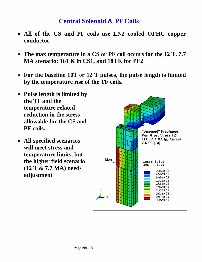
Central Solenoid & PF Coils
• All of the CS and PF coils use LN2 cooled OFHC copperconductor
• The max temperature in a CS or PF coil occurs for the 12 T, 7.7MA scenario: 161 K in CS1, and 183 K for PF2
• For the baseline 10T or 12 T pulses, the pulse length is limitedby the temperature rise of the TF coils.
• Pulse length is limited bythe TF and thetemperature relatedreduction in the stressallowable for the CS andPF coils.
• All specified scenarioswill meet stress andtemperature limits, butthe higher field scenario(12 T & 7.7 MA) needsadjustment

Page No. 16
Neutronics and Shielding
• Nuclear heating has been computed for the major components(eg- magnets, vacuum vessel and PFC’s) and can beaccommodated.
• Neutronics analyses indicate that the insulation must withstand1.47 x 1010 rads for a cumulative fusion energy of 5 TJ DT and0.5 TJ DD. This is the peak, end of life value and occurs at themagnet surface at the inboard mid-plane.It is expected that insulation materials can be identified that canmeet the exposure limits.
1 08
1 09
1 01 0
1 01 1
0 1 0 2 0 3 0 4 0 5 0
En
d-o
f-lif
e I
nsu
lato
r D
ose
(R
ad
)
Depth in IB Magnet at Midplane (cm)
Total Fusion Energy of 5 TJ DT and 0.5 TJ DDInboard Magnet at Midplane
2.7 MW/m2 Neutron Wall LoadingPassively Cooled FW
Radial variation of insulator dose in inboard leg of TF coil

Page No. 17
Activation & Radiation Exposure
• The PFC’s produce the highest levels of specific activity anddecay heat. However, the favorable operational schedule allows forthe decay of short-lived radionuclides between pulses resulting inlow levels of activity and decay heat at shutdown.
• The biological dose rates behind the vacuum vessel and thedivertor remain high during the first year following shutdown
• The vacuum vessel jacket/shield thickness, in conjunction withthe shielding provided by the TF coils and port plugs, is suchthat "hands on" ex-vessel maintenance will be permitted withina few hours after shutdown.
• At the end of the machine life, all components qualify fordisposal as Class C low level waste.
10- 5
10- 4
10- 3
10- 2
10- 1
100
101
102
103
104
105
106
107
100 101 102 103 104 105 106 107 108
Behind OB VVBehind OB MagnetBehind the Steel Plug
Dos
e R
ate
(mre
m/h
)
Time Following Shutdown (s)
1 w1 h 1 d 1 mo 1 y
Limit for Hands-on
Biological dose ratesat the midplane as afunction of timefollowing shutdown.
Page No. 18
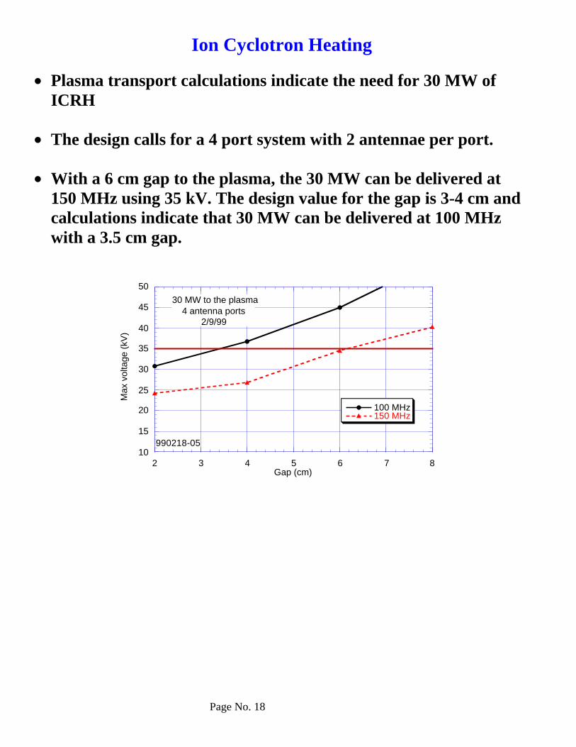
Ion Cyclotron Heating
• Plasma transport calculations indicate the need for 30 MW ofICRH
• The design calls for a 4 port system with 2 antennae per port.
• With a 6 cm gap to the plasma, the 30 MW can be delivered at150 MHz using 35 kV. The design value for the gap is 3-4 cm andcalculations indicate that 30 MW can be delivered at 100 MHzwith a 3.5 cm gap.
10
15
20
25
30
35
40
45
50
2 3 4 5 6 7 8
100 MHz150 MHz
Max
vol
tage
(kV
)
Gap (cm)
30 MW to the plasma4 antenna ports
2/9/99
990218-05

Page No. 19
Ion Cyclotron 2-Strap Antenna Design
• Two strap antennas will be located at four midplane ports.
Current strap, grounded at each end
Faraday shield(one side only)
Port flange

Page No. 20
Fueling & Vacuum Pumping
• Pellet injection is being considered from the outside mid-plane,vertically and from the inside lower quadrant aimed towardsthe plasma center.
• A tritium-rich pellet source will be used for core fueling and adeuterium-rich gas source for edge fueling.
- conventional gas puffing system with all-metalelectromagnetic valves (four toroidal stations at twopoloidal locations at each divertor level)- pellet injection system with two identical (redundant)injectors.
• The design vacuum pumping speed is 200 torr-liter/s for a 20spulse length. The base pressure is 10-7 torr for fuel gases (H, D,T) and 10-9 torr for impurities; operating pressure is~10-4 to 10-3
torr.- 16 cryopumps are used (8 each top and bottom at
alternate divertor ports) close coupled to the torus in thepumping duct directly from the double null divertor.
Divertor ductCryopump
Divertor Midplane port
Page No. 21
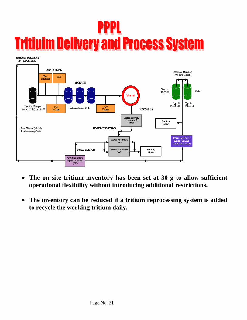
• The on-site tritium inventory has been set at 30 g to allow sufficientoperational flexibility without introducing additional restrictions.
• The inventory can be reduced if a tritium reprocessing system is addedto recycle the working tritium daily.

Page No. 22
Cryoplant
• FIRE magnets obtain nitrogen from a specially built, “leased”LN2 production facility
• No upfront plant installation costs• ~10M$/year nitrogen cost
• FIRE uses the Alcator C-Mod method of one pump andindividual regulator valves for each flow circuit.
• A subcooler is used to provide 80 °K liquid nitrogen to the coils.
• The magnets are kept cold overnight and weekends, and onlywarmed up to room temperature during maintenance periods
• The storage requirements are higher than they were in the CITdesign:-The energy dissipated is higher than in CIT (18.7 GJ vs. 12GJ)-The number of pulses is higher than in CIT (40/week vs.20/week)-note: if 7,000 gallon trucks are used, this would require 60trucks/day
The amount of radioactive nitrogen-13 generated is small and wouldbe within allowables for most site boundaries.
• One day hold-up of N13 unnecessary• One hour hold-up ok with nitrogen flush• Eliminate hold-up if use helium flush

Page No. 23
Power Supplies
• A 10 T pulse will require 14 Gigajoules for the TF system and 2Gigajoules for the CS/PF magnets; the Peak power is 542 MVAand 412 MVA, respectively.
• Power equipment for TF and CS/PF magnets includes thyristorrectifiers, resistor banks, and switching-interrupter circuits.-The total pulse rating of the rectifiers is approximately 1000MVA for the 10 Tesla pulse.-For a long-pulse option (eg- 4 Tesla, 2 MA), the total 214second long-pulse rectifier rating is 345 MVA.
• For the 12 Tesla 7.7 MA case: -An additional 200 MVA of thyristor rectifiers would provide ashort-pulse 12 Tesla 7.7 MA capability-An extended flattop at 12 Tesla could be obtained by insertingadditional TF rectifiers in series to boost the TF chargingvoltage, bringing the total rectifier rating to 1850 MVA. Anoption would be to power the additional 650 MVA from a localMG storing at least 1.7 Gigajoules of energy.
- 2 0 0
0
200
400
600
800
1000
- 2 0 - 1 0 0 1 0 2 0 3 0 4 0 5 0
10 TESLA FIRE PF+ TF TOTAL POWER WAVEFORMS
MW TOTALMVA TOTALMVAR Total
Meg
aWat
ts;
Meg
aVA
Time (sec)
Note: Power Requirements could be reduced significantly if all Cu TF coils are used

Page No. 24
POWER REQUIREMENTS FOR FIRE
(BeCu vs OFHC Cu TF)
BeCu TF Coil Inner Legs10T (20s) 12T (12s)
Peak Power(MW)
Peak Energy(GJ)
Peak Power(MW)
Peak Energy(GJ)
TF 490 11.5 815 11.5PF 250 2.2 360 3.7RF 60 1 60 0.6∑ 800 14.7 1235 15.8Grid 550
(TF&RF)12.5 600
(TFbase)10.9
MG 250 (PF) 2.2 635(TFsupp
&PF&RF)
4.9
All Cu TF Coils10T (45s) 12T (25s)
Peak Power(MW)
Peak Energy(GJ)
Peak Power(MW)
Peak Energy(GJ)
TF 267 12.6 345 13.2PF 250 5 360 4.6RF 60 2.3 60 1.3∑ 577 19.9 765 19.1Grid 577 (All
Systems)19.9 404
(TF&RF)14.5
MG 0 0 360 (PF) 4.6
The OFHC (“All Cu”) option will be studied further in FY01

Page No. 25
Remote Maintenance
• The strategy is to employ hands-on maintenance to the fullestextent possible. The activation levels outside the thermal shieldare low enough to permit hands-on maintenance; temporary localshielding will be necessary when the duct shield plugs areremoved.
• In-vessel components will generally be removed as integralassemblies and transferred to the hot cell for repair orprocessing as waste.
• In situ operations will be limited to inspection, vacuum windowreplacement, leak testing and, if necessary, dust removal.
• Remote maintenance will continue to be a driver for design ofinterfaces. Components have been given a classification andpreliminary requirements are being accommodated in the layout of facilities andthe site.
Page No. 26
Safety
• Release targets for tritium, and activated tungsten, air and nitrogen havebeen established.
• A goal is to keep the total on-site tritium inventory below 30 g-Site can be classified as a low hazard nuclear facility
• Confinement barriers:-double-walled vacuum vessel is a highly reliable primary barrier-thermal shield will serve as a moderately reliable 2nd barrier-double confinement will be implemented in all penetrations attached tothe vacuum vessel
• Examination of the potential safety concerns associated with the energysources has not yet revealed any events that pose a serious challenge tothe radiological confinement function. A preliminary analysis has beendone for:• Long term thermal response and passive decay heat removal under a
complete loss of coolant condition for the divertor and VV -- decayheat is not a serious concern and oxidation of the activated PFCsurfaces will not be significant.
• Break in the divertor or VV cooling lines inside of the VV—pressuredoes not rise to a level expected to compromise the VV radiologicalconfinement integrity. Furthermore the chemical energy from Be-steam and W-steam interactions does not threaten the radiologicalconfinement function of the VV.
• Deflagration and/or detonation of hydrogen upon mixing with air--From the accident perspective, hydrogen from Be/steam andW/steam reactions was not of concern, however the tritium on thecryopumps must be controlled. The deflagration limit of 30 g- molestranslates into a deflagration limit of ~ 300 g DT. Regeneration willbe scheduled frequently enough to stay well below this limit.
• The control of plasma energy, magnet energy, loss of vacuum events, orpotential cryogen/water interactions have not yet been analyzed.

Page No. 27
Pressure in FIRE plasma chamber resulting from an in-vessel break of thevacuum vessel cooling system
Radiological Release Targets for FIRE
NormalOperationa
No-evacuation Limit
Dose Limit 0.1 mSv/yr(10 mrem/yr)
10 mSv (1 rem) per offnormal event
Meteorology Yearlyaverage
Best-estimate or AverageWeather
SiteBoundary
1 km 1 km 1 km
Release Point Elevated via100 m stack
Ground
Elevatedvia 100 m stack
Tritium asHTO
8 g/a 150 g 1.3 kg
Activated Wdust
5 kg/a 5 Mg 53 Mg
Ar-41 5 Ci/hr b bN-13 8 Ci/hr b bC-14 0.1 Ci/hr b b
• Release targets have been reduced by a factor of ~ 10 relative to regulatorylimits as an implementation of the ALARA principle.
• Not considered an accident hazard because of low inventory in FIRE

Page No. 28
Facilities & Siting
• A conceptual layout has been developed for the safety and non-safetyrelated buildings based on a “green field” site. It may also be possibleto adapt an existing facility to the FIRE project.
• The test cell size is determined by the size of the cryostat and spacerequired for remote handling casks at ports (casks are 8 m in lengthand about 1.9 m in width). Several strategies are under consideration forthe design of RH cask vehicles. A tentative routing for the vehicles toother parts of the facility has been selected.
• FIRE will take advantage of the shielding provided by the thick outerwall of the vacuum vessel and the magnet system. Port objects willprovide equivalent shielding, making them both long and heavy, butwith the result that the outboard end of the port objects will not becomeradioactive. The plasma facing end will be a strong radiation source,however the size and spacing of the ports make it impractical to includeshielding in the casks. The remote handling requirements on the facilityfor routing and storage of these items is being evaluated.
• The hot cell concept assumes that some port mounted objects can berepaired. The extent and nature of these processes are not yet welldeveloped, but it is expected that they will include replacement ofdivertor strike plates, and repair of diagnostic and plasma heatingdevices. Radioactive materials which cannot be returned to thetokamak will be processed in the hot cell to recover tritium fromberyllium and will then be size reduced by sawing or cutting, andencapsulated for subsequent shipment to a waste repository.
• Some building requirements are not yet well developed, but a preliminaryallowance has been made. For example, the cryogenics systems buildingis used to house indoor parts of the liquid nitrogen system. It alsohouses a liquid helium refrigerator for the cryopumps in the vacuumvessel and in the diagnostic neutral beam.
• Magnets will be cooled before each operating pulse, using liquidnitrogen, supplied commercially.

Page No. 29
Building 11 - Tokamak and Hot Cell Building
39.0 m
GradeEle. 0
5.8 m
3.0 m4.595 m
22.6m
TF Busbar Array
CS Busbar Array

Page No. 30
Assembly and Mockup Hall
Remote handling Cask and Vehicle Op. & Maint. Space
Hot Cell
Hot Cell Remote Manipulator
Assembly and Maintenance Bridge Crane
Crane Enclosure
Movable Test Cell Shield Barrier
Hot Cell / Repair Cell Control Rooms
Port Object Repair Cell
Remote Handling Cask and Vehicle Operation and Maintenance Space
Tokamak Test Cell
Remote Handling Tool Storage and Maintenance Room
Decon Cell
Tool Test Cell
Hot Cell
Assembly Hall, Tokamak Building, and Hot Cell - NS Section
Assembly Hall, Tokamak Building, and Hot Cell - Plan View

Page No. 31
Magnet Cooling
CS 1 busbar set (below)
TF busbar set
PF 4 busbar set (above)
PF 3 busbar set
CS 2 busbar set (below)
CS 3 busbar set (below)
PF 1 busbar set
PF 2 busbar set
Pellet Injector/Gas Injection
LHe Aux. Cold Box(es)
Diagnostics Systems (below)
Vacuum Roughing System
Tritium Storage Vault
Fuel Purification and Isotopic Separation Equipment - in gloveboxes
Cooling Loop Water Purification Systems
Vacuum Vessel/FW Cooling System Equipment
Hot Cell HVAC and Mechanical System Support
Divertor Cooling System Equipment

Page No. 32
22
23
2125
15
24
28
14 12
North
27
2650 m
Legend:Safety Related Buildings11 - Tokamak and Hot Cell Building12 - Radioactive System Support Building14 - Radwaste Systems Building15 - Emergency Power Supply Building
Non-Safety Related Buildings21 - Assembly and Mock-up Hall22 - Magnet Power Conversion Building23 - Cooling Systems Building24 - Cryogenic System Building25 - ICRH Power Supply Building26 - Laboratory Office Building27 - Control and Operations Building28 - Utility Services Building
SwitchYard
Liquid Nitrogen Storage
Cooling Tower
Preliminary Site Layout
Page No. 33
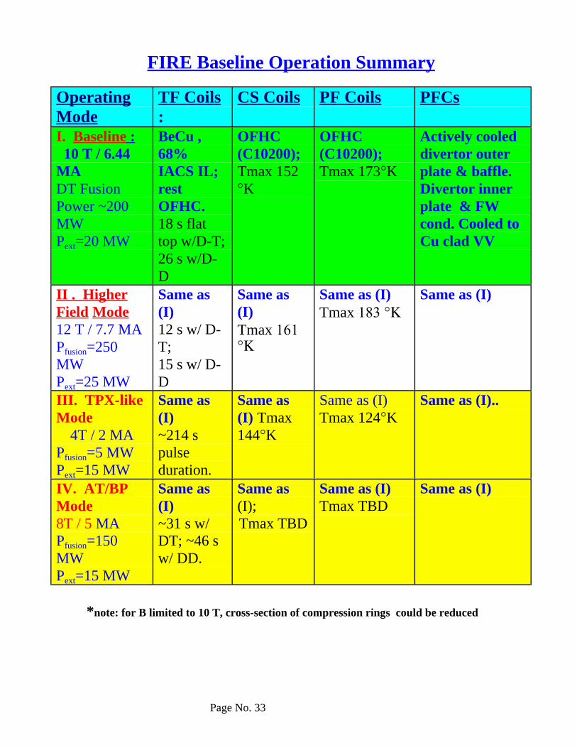
FIRE Baseline Operation Summary
OperatingMode
TF Coils:
CS Coils PF Coils PFCs
I. Baseline : 10 T / 6.44MADT FusionPower ~200MWPext=20 MW
BeCu ,68%IACS IL;restOFHC.18 s flattop w/D-T;26 s w/D-D
OFHC(C10200);Tmax 152°K
OFHC(C10200);Tmax 173°K
Actively cooleddivertor outerplate & baffle.Divertor innerplate & FWcond. Cooled toCu clad VV
II . HigherField Mode12 T / 7.7 MAPfusion=250MWPext=25 MW
Same as(I)12 s w/ D-T;15 s w/ D-D
Same as(I)Tmax 161°Κ
Same as (I)Tmax 183 °Κ
Same as (I)
III. TPX-likeMode
4T / 2 MAPfusion=5 MWPext=15 MW
Same as(I)~214 spulseduration.
Same as(I) Tmax144°K
Same as (I)Tmax 124°K
Same as (I)..
IV. AT/BPMode8T / 5 MAPfusion=150MWPext=15 MW
Same as(I)~31 s w/DT; ~46 sw/ DD.
Same as(I);Tmax TBD
Same as (I)Tmax TBD
Same as (I)
*note: for B limited to 10 T, cross-section of compression rings could be reduced

Page No. 34
CONCLUSIONS
• Design has addressed all major systems, facilities and safety• FY99 Report available• FY00 Interim Report available now
• Baseline design meets or exceeds initial requirements for 10 T, 6.4MA, flat-top > 10 s
• Possibility exists for higher fields (eg 12 T, 7.7 MA) and longerpulses at lower fields(eg 8T, 5 MA, 46 s)
• Cost estimates underway
Issue: Divertor and first wall cooling details will have to be refinedas the hardware details evolve.
Issue: Preliminary divertor disruption analyses indicate highstresses in module / vessel attachments for the current design. Moredetailed analyses are planned to better quantify loads. Studies willalso consider toroidal electrical connections between modules toreduce torques.
Issue: For B limited to 10 T, compression ring cross-section could bereduced; inner leg material could change to BeCu with 77% IACSand pulses could lengthen slightly
Issue: For a bucked and wedged design and B limited to 11.5 T, TFcoils could be entirely OFHC copper; this would reduce power andTF coil costs and will be explored in FY01