Embed Size (px)
Citation preview

Ibañez C, Aguado JV, Romero ML, Espinos A, Hospitaler A. Fire design method for concrete filled tubular columns
based on equivalent concrete core cross‐section. Fire Safety Journal. 2015; 78:10‐23.
doi: 10.1016/j.firesaf.2015.07.009
1
Fire design method for concrete filled tubular columns based on
equivalent concrete core cross-section
Carmen Ibañeza, José V. Aguadob, Manuel L. Romeroc*, Ana Espinosc, Antonio Hospitalerc
a Departamento de Mecánica y Construcción
Universitat Jaume I, Castelló, Spain
b Institut de Recherche en Génie Civil et Mécanique (GeM)
Ecole Centrale de Nantes, France
c Instituto de Ciencia y Tecnología del Hormigón (ICITECH)
Universitat Politècnica de València, Spain
* corresponding author: [email protected]
ABSTRACT
In this work, a method for a realistic cross-sectional temperature prediction and a
simplified fire design method for circular concrete filled tubular columns under axial
load are presented. The generalized lack of simple proposals for computing the cross-
sectional temperature field of CFT columns when their fire resistance is evaluated is
evident. Even Eurocode 4 Part 1-2, which provides one of the most used fire design
methods for composite columns, does not give any indications to the designers for
computing the cross-sectional temperatures. Given the clear necessity of having an
available method for that purpose, in this paper a set of equations for computing the
temperature distribution of circular CFT columns filled with normal strength concrete is
provided. First, a finite differences thermal model is presented and satisfactorily
validated against experimental results for any type of concrete infill. This model
considers the gap at steel-concrete interface, the moisture content in concrete and the

Ibañez C, Aguado JV, Romero ML, Espinos A, Hospitaler A. Fire design method for concrete filled tubular columns
based on equivalent concrete core cross‐section. Fire Safety Journal. 2015; 78:10‐23.
doi: 10.1016/j.firesaf.2015.07.009
2
temperature dependent properties of both materials. Using this model, a thermal
parametric analysis is executed and from the corresponding statistical analysis of the
data generated, the practical expressions are derived. The second part of the paper deals
with the development of a fire design method for axially loaded CFT columns based on
the general rules stablished in Eurocode 4 Part 1-1 and employing the concept of room
temperature equivalent concrete core cross-section. In order to propose simple
equations, a multiple nonlinear regression analysis is made with the numerical results
generated through a thermo-mechanical parametric analysis. Once more, predicted
results are compared to experimental values giving a reasonable accuracy and slightly
safe results.
Keywords: Concrete filled tubular column; Numerical model; Finite differences;
Temperature prediction; Simple calculation procedure; Equivalent cross-section; Fire
resistance; Eurocode 4.
NOTATION
A/V Section factor
CFT Concrete filled tube
CXXX-T-L-FF-EE (i.e. C159-6-3-30-0), where C stands for circular, XXX is the
diameter in mm, “T” the thickness in mm, L the nominal length in meters, FF the
nominal concrete strength in MPa, and EE is the applied eccentricity.
D Diameter of the column
FC Fiber reinforced concrete
FRR Fire resistance rating
fc Compressive cylinder strength of concrete at room temperature (test date)
fy Yield strength of structural steel at room temperature

Ibañez C, Aguado JV, Romero ML, Espinos A, Hospitaler A. Fire design method for concrete filled tubular columns
based on equivalent concrete core cross‐section. Fire Safety Journal. 2015; 78:10‐23.
doi: 10.1016/j.firesaf.2015.07.009
3
L Length of the column
l Buckling length in the fire situation
RC Reinforced concrete
T Temperature
t Thickness of the steel tube
= N/NRd Axial load level
Relative error

Ibañez C, Aguado JV, Romero ML, Espinos A, Hospitaler A. Fire design method for concrete filled tubular columns
based on equivalent concrete core cross‐section. Fire Safety Journal. 2015; 78:10‐23.
doi: 10.1016/j.firesaf.2015.07.009
4
1. INTRODUCTION
In recent years, the use of concrete filled tubular (CFT) columns has increased and
concurrently, the interest of engineers and architects in the fire design of these
composite columns has also augmented. In fire situation, CFT columns show a high
resistance even when no external protection is used. The steel tube protects the concrete
core from the direct exposure to fire and, in turn, the concrete infill delays the heating of
the steel profile. Mechanical properties of both materials degrade as temperature
increases, but steel loses its resistance faster than concrete. Determining with accuracy
the cross-sectional temperature distribution when modeling a CFT column in fire is
crucial, and moreover if a realistic fire resistance prediction is expected.
European code EN 1994-1-2 [1] in its Clause 4.3.5.1 establishes a general method
to study the fire resistance of composite columns. This procedure takes into account the
temperature dependent thermal and mechanical properties of the material but no
recommendations are given regarding the calculation of the cross-sectional temperature
field along time.
A simple calculation model explicitly for CFT sections in fire proposed in Annex
H of the same code [1] indicates that the temperature distribution shall be calculated
neglecting the thermal resistance at steel-concrete interface for simplicity and in
accordance with Clause 4.4.2. This section provides a series of guidelines regarding
thermal actions, variation of thermal properties with temperature and concrete moisture
content for thermal response in advanced calculation models, which are only applied in
specific situations when the actual behavior is required.
In summary, EN 1994-1-2 [1] does not provide any direct method to obtain the
time dependent cross-sectional temperature distribution in a CFT column for the
standard fire classes (R30, R60, R90 and R120). Designers are obliged to turn to

Ibañez C, Aguado JV, Romero ML, Espinos A, Hospitaler A. Fire design method for concrete filled tubular columns
based on equivalent concrete core cross‐section. Fire Safety Journal. 2015; 78:10‐23.
doi: 10.1016/j.firesaf.2015.07.009
5
numerical models or to implement complex methods available in published research
works [5].
Thermal analysis is the first step to carry out when the whole response of a CFT
column is analyzed. In the reviewed literature, some of the studies considered realistic
features regarding the heat transfer process, such as the three-dimensional model
presented by Espinos et al. [2] which took into account the gap at the steel-concrete
interface and the water content of the concrete core; or the numerical model developed
by Lu et al. [3] which assumed a heat contact conductance parameter to represent the
gap between the two materials. But these works focused on models to study the global
fire behavior of CFT columns. Computing the temperature distribution of the column
was just an implicit step within the entire calculation. Therefore, they do not present any
simple and specific procedure for computing the cross-sectional temperature.
With regard to studies dealing exclusively with the thermal analysis of CFT
columns, just few publications can be located. A numerical method using the Green’s
function approach was developed by Wang et al. [4] for protected steel members and
later it was extended by Wang and Tan [5] to solve the heat transfer problem in CFT
columns. However, the concrete and steel properties were considered temperature
independent, perfect contact between materials was assumed and also the presence of
moisture in the concrete was neglected. These conservative assumptions made the
method lose accuracy.
Another approach to solve the sectional heat transfer problem in CFT columns is
employing finite differences. Hence, Lie [6] developed a formulation for circular CFT
columns based on the methodology proposed by Dusinberre [7]. Again, perfect contact
was assumed at steel-concrete interface.

Ibañez C, Aguado JV, Romero ML, Espinos A, Hospitaler A. Fire design method for concrete filled tubular columns
based on equivalent concrete core cross‐section. Fire Safety Journal. 2015; 78:10‐23.
doi: 10.1016/j.firesaf.2015.07.009
6
Although some realistic features were not considered, these works presented
effective procedures to obtain temperature distribution at the cross-section of CFT
columns. In spite of this, since no straightforward equations were provided, designers
might find tedious and time-consuming implementing them in the daily practice.
Relating to fire design methods for CFT columns following the general rules of
EN 1994-1-2 [1], some works can be found where the authors have treated the cross-
sectional thermal analysis step separately. Thus, researchers like Espinos et al. [8]
proposed an effective design procedure as a result of an extensive parametric study
carried out by means of their validated three-dimensional model [2]. However, this
method assumed an equivalent temperature for the concrete core so the cross-sectional
temperature distribution was no explicitly calculated. In the same line, Yu et al. [9]
developed a simple calculation method for the fire resistance of CFT columns but again
on the assumption of average temperatures for both steel tube and concrete core cross-
sections.
This work can be divided into two parts: on the one hand, practical expressions
for computing the cross-sectional temperatures of circular CFT columns are developed;
on the other hand, a simple design method for obtaining the fire resistance of axially
loaded CFT columns is proposed.
Therefore, the outline of this paper is as follows. First, a finite differences method
for solving the heat transfer problem is developed improving the initial approach of
Dusinberre [7] by considering the effect of the gap conductance at steel-concrete
interface and, in general, all the detected nonlinearities involved in the heat transfer
process to obtain a response as realistic as possible. The finite differences method is
valid for a wide range of concrete infill: plain, bar reinforced and steel fiber reinforced

Ibañez C, Aguado JV, Romero ML, Espinos A, Hospitaler A. Fire design method for concrete filled tubular columns
based on equivalent concrete core cross‐section. Fire Safety Journal. 2015; 78:10‐23.
doi: 10.1016/j.firesaf.2015.07.009
7
concrete of both normal and high strength. The thermal model is validated against
experimental results showing good agreement.
Next, an extensive thermal parametric analysis is carried out in order to obtain a
regression equation for calculating the cross-sectional temperature field. Although the
thermal model developed has proven to be valid for protected and unprotected CFT
columns with any type of concrete infill, as a first step, the parametric analysis and the
proposed adjustment equations are specifically focused on unprotected circular CFT
columns filled with normal strength concrete. In order to extend the current equations or
to obtain new temperature expressions for other types of concrete infill, it is necessary
to perform the pertinent parametric analysis taking into account the corresponding
thermal properties.
The concept of equivalent concrete core cross-section at room temperature is
exposed right after, since it is the starting point to develop the fire design method
proposed, which is verified against experimental results.
Finally, a case of CFT column fire design is included to exemplify the use of the
calculation procedure presented.
2. HEAT TRANSFER MODEL
The heat transfer model involves the calculation of the temperatures given by the
fire curve to which the column is exposed and the determination of column cross-
sectional temperatures.
The model formulation is based on the finite differences method with an explicit
scheme and follows the line proposed by Dusinberre [7]. Previously, Lie [6] had already
taken as a basis the same approach to solve the heat transfer problem for circular CFT
Ibañez C, Aguado JV, Romero ML, Espinos A, Hospitaler A. Fire design method for concrete filled tubular columns
based on equivalent concrete core cross‐section. Fire Safety Journal. 2015; 78:10‐23.
doi: 10.1016/j.firesaf.2015.07.009
8
columns but ignoring the gap conductance that appears between the steel tube and the
concrete core which clearly reduces the thermal response accuracy.
In this paper, only the expressions to obtain cross-sectional temperatures are
presented since the derivation of these equations is explained with detail in previous
works [7].
Discretization of the section
The nomenclature used by Lie [6] will be maintained in order to make easier any
comparison between both formulations. Due to axisymmetric conditions, the heat
transfer problem becomes unidirectional what simplifies the discretization of the section
as well as the calculation process.
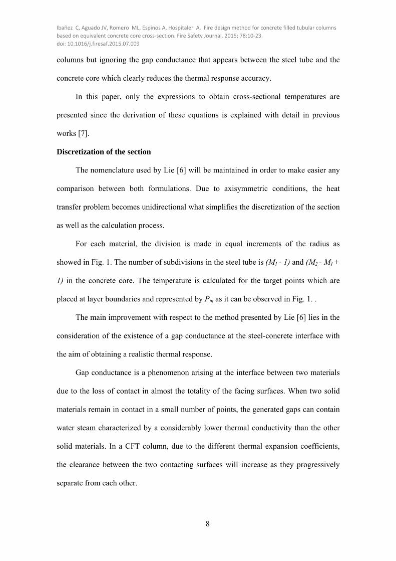
For each material, the division is made in equal increments of the radius as
showed in Fig. 1. The number of subdivisions in the steel tube is (M1 - 1) and (M2 - M1 +
1) in the concrete core. The temperature is calculated for the target points which are
placed at layer boundaries and represented by Pm as it can be observed in Fig. 1. .
The main improvement with respect to the method presented by Lie [6] lies in the
consideration of the existence of a gap conductance at the steel-concrete interface with
the aim of obtaining a realistic thermal response.
Gap conductance is a phenomenon arising at the interface between two materials
due to the loss of contact in almost the totality of the facing surfaces. When two solid
materials remain in contact in a small number of points, the generated gaps can contain
water steam characterized by a considerably lower thermal conductivity than the other
solid materials. In a CFT column, due to the different thermal expansion coefficients,
the clearance between the two contacting surfaces will increase as they progressively
separate from each other.

Ibañez C, Aguado JV, Romero ML, Espinos A, Hospitaler A. Fire design method for concrete filled tubular columns
based on equivalent concrete core cross‐section. Fire Safety Journal. 2015; 78:10‐23.
doi: 10.1016/j.firesaf.2015.07.009
9
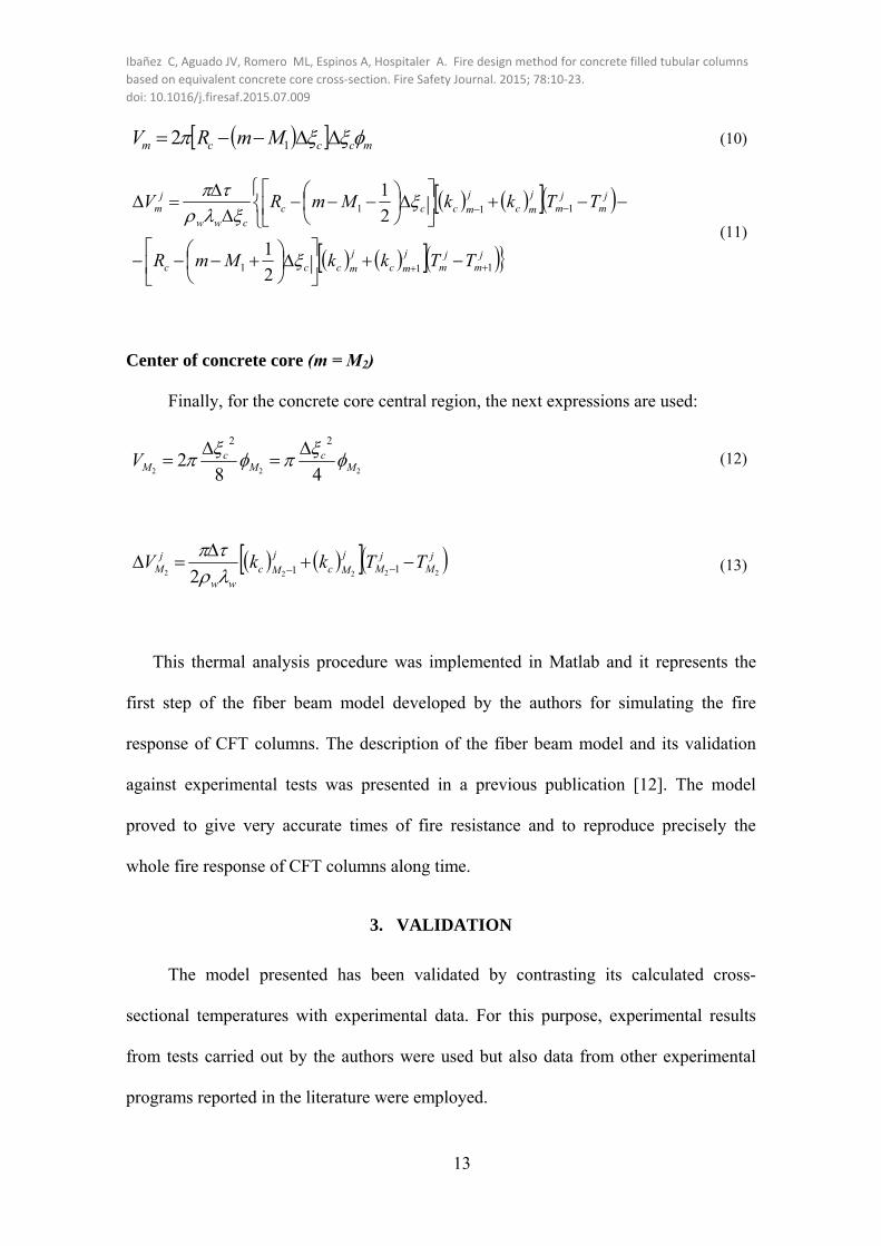
In order to represent this event, the node physically placed at the steel-concrete
boundary is theoretically split into two nodes: one node belongs to the steel tube inner
surface and the second node is located in the concrete core outer surface, Fig. 2. Thus, it
is possible to consider the steel-concrete gap as a new layer of thickness zero
characterized by a thermal conductance that reproduces the sudden drop of temperatures
from the steel tube to the concrete core.
The thickness of all the layers in the steel tube is Δξs, except for the layer at the
steel-concrete boundary which is ½ Δξs thick. The same occurs in the concrete core,
while all the inner layers have a thickness of Δξc, the layer at steel-concrete interface
and the layer at the center of the column are ½ Δξc.
For deriving the next equations, an arc of 1 radian is used and the depth in the
axial direction is taken as unity as pointed out by Dusinberre [7].
2.1. CROSS-SECTIONAL TEMPERATURES
In this work, the whole length of the column is supposed to be uniformly exposed
to a fire. Just for description purposes, it is assumed that the fire evolution follows the
standard fire curve ISO 834 [10][11]. Note that this curve can be replaced by the heating
curve characterizing an actual fire or by another standard fire curve. ISO 834 is
represented by the next expression:
)18log(34520 jfT (1)
where τ is the time in minutes and jfT is the fire temperature, in ºC, at time τ = jΔτ.
For a CFT column, at time τ = (j+1)Δτ, the temperature at the different points of
the section can be calculated as follows:

Ibañez C, Aguado JV, Romero ML, Espinos A, Hospitaler A. Fire design method for concrete filled tubular columns
based on equivalent concrete core cross‐section. Fire Safety Journal. 2015; 78:10‐23.
doi: 10.1016/j.firesaf.2015.07.009
10
Equations for fire-steel boundary (m = 1)
jjjs
js
ss
sjpss
ss
jjf
jjfpf
ss
sjps
js
sjj
TTkkRc
RTTh
TTRc
RTT
21212
1
4
1
4
11
1
4
2
273273
4
2
(2)
where 1
1jT is the temperature at the surface of the steel tube at time τ = (j+1)Δτ, Rs is
the external CFT column radius; Δξs is the thickness of steel tube layers.; ρs, cps and ks
are the density, specific heat and conductivity of steel; f is the emissivity of the fire;
p is the emissivity of the exposed surface (steel tube); σ is the Stephan-Boltzmann
constant; and h is the coefficient of convective heat transfer.
Equations for inside steel tube (1 < m < M1 - 1)
To obtain the temperature at the inner layers of the steel tube the expression to be
used is the next,
jm
jm
j
msj
msssj
mj
mj
msj
ms
ss
sssjps
js
jm
jm
TTkkmRTTkk
mRmRc
TT
1111
21
2
1
2
3
)1(2
(3)
where1j
mT is the temperature at point m inside the steel at time τ = (j+1)Δτ.
Equations for steel-concrete boundary: Steel tube inner surface (m = M1 - 1)
As explained above, the contact between the steel tube and the concrete core is modeled
in a realistic way by modeling the gap conductance at the steel-concrete interface.
The temperature at the steel tube inner surface at time τ = (j+1)Δτ is given by:

Ibañez C, Aguado JV, Romero ML, Espinos A, Hospitaler A. Fire design method for concrete filled tubular columns
based on equivalent concrete core cross‐section. Fire Safety Journal. 2015; 78:10‐23.
doi: 10.1016/j.firesaf.2015.07.009
11
jM
jMscgap
jM
jM
j
Msj
Ms
ss
sssjps
js
jM
jM
TTRhTTkk
MR
MRc
TT
111111
11
11212
12
1
111
2
2
5
4
9
(4)
where hgap is the thermal gap conductance at steel-concrete interface. It is defined as the
conductance of the separation layer appearing between the two components.
Equations for steel-concrete boundary: Concrete core outer surface (m = M1)
On the other hand, the temperature at the surface of concrete core in the steel-concrete
boundary at time τ = (j+1)Δτ is given by:
jM
jM
j
Mcj
Mcc
c
jM
jMccgap
cc
cj
Mjpw
jw
jpc
jc
jM
jM
TTkkR
TTRhRcc
TT
11
12
1
1111
11
1
11
2
2
4
(5)
where ρc, cpc and kc are the density, specific heat and conductivity of concrete; Δξc is the
thickness of concrete core layers; ρw and cpw are the density and specific heat of water;
is the concrete moisture content; and Rc is the concrete core radius.
Equations for inside concrete core (M1 +1 ≤ m < M2)
For the interior points of the concrete core, except for the point located at the
center of the concrete core cross-section, the temperature at time τ = (j+1)Δτ can be
determined by the next equation:
jm
jm
j
mcj
mccc
jm
jm
j
mcj
mccc
cccj
mjpw
jw
jpc
jc
jm
jm
TTkkMmR
TTkkMmR
MmRccTT
111
111
21
1
2
1
2
1
2
(6)

Ibañez C, Aguado JV, Romero ML, Espinos A, Hospitaler A. Fire design method for concrete filled tubular columns
based on equivalent concrete core cross‐section. Fire Safety Journal. 2015; 78:10‐23.
doi: 10.1016/j.firesaf.2015.07.009
12
Equations for the center of concrete core (m = M2)
The temperature at the center of the concrete core at time τ = (j+1)Δτ is given by:
jM
jM
j
Mcj
Mc
cjpc
jc
jM
jM TTkk
cTT
222222 1121 2
(7)
2.2. CONTENT OF MOISTURE IN THE CONCRETE CORE
The effect of moisture in the concrete is taken into account by assuming that the
initial volume of moisture in the concrete starts to evaporate when the temperature
reaches 100ºC. During the evaporation all the heat provided is consumed in this process
so that the temperature does not increase until the water has evaporated completely.
INITIAL CONTENT OF MOISTURE
The initial content of moisture expressed in volume and the volume of moisture
evaporated during a period of time Δτ is given by:
Steel-concrete boundary: Concrete core outer surface (m = M1)
For the external layer of the concrete core, the expressions are:
111 4242 Mc
ccM
cccM RRV
(8)
jM
jM
j
Mcj
Mcc
c
jM
jMcc
cww
jM
TTkkR
TTRV
11
1
1111
111
2
2
(9)
Inside concrete core (M1 +1 ≤ m < M2)
In the case of the inner regions of the concrete core, except for the point
representing the central area, the equations are:
Ibañez C, Aguado JV, Romero ML, Espinos A, Hospitaler A. Fire design method for concrete filled tubular columns
based on equivalent concrete core cross‐section. Fire Safety Journal. 2015; 78:10‐23.
doi: 10.1016/j.firesaf.2015.07.009
13
mcccm MmRV 12 (10)
jm
jm
j
mcj
mccc
jm
jm
j
mcj
mccccww
jm
TTkkMmR
TTkkMmRV
111
111
2
1
2
1
(11)
Center of concrete core (m = M2)
Finally, for the concrete core central region, the next expressions are used:
222 482
22
Mc
Mc
MV
(12)
jM
jM
j
Mcj
Mcww
jM TTkkV
22222 112
(13)
This thermal analysis procedure was implemented in Matlab and it represents the
first step of the fiber beam model developed by the authors for simulating the fire
response of CFT columns. The description of the fiber beam model and its validation
against experimental tests was presented in a previous publication [12]. The model
proved to give very accurate times of fire resistance and to reproduce precisely the
whole fire response of CFT columns along time.
3. VALIDATION
The model presented has been validated by contrasting its calculated cross-
sectional temperatures with experimental data. For this purpose, experimental results
from tests carried out by the authors were used but also data from other experimental
programs reported in the literature were employed.

Ibañez C, Aguado JV, Romero ML, Espinos A, Hospitaler A. Fire design method for concrete filled tubular columns
based on equivalent concrete core cross‐section. Fire Safety Journal. 2015; 78:10‐23.
doi: 10.1016/j.firesaf.2015.07.009
14
3.1. EXPERIMENTAL TESTS FOR VALIDATION
In order to validate the thermal model, data from two experimental campaigns
were used. On the one hand, results from tests carried out by the authors and reported in
previous works [13][14] were employed. All the CFT columns were tested at AIDICO
(Instituto Tecnológico de la Construcción) in Valencia, Spain. The analyzed specimens
comprised columns filled with normal and high strength concrete of different type infill:
plain, bar reinforced and steel fiber reinforced concrete, and, in all cases, the aggregates
were calcareous. These specimens were heated following the standard ISO-834 curve
[10][11]. The main characteristics of these columns can be found in Table 1 .
On the other hand, data from tests performed by Lie and Chabot [15] were also
used so that the validation process was not limited to comparison with own
experimental results. The thermal response of twenty-three columns specimens tested at
the National Research Council of Canada (NRCC) was simulated. These columns were
filled with normal strength concrete, with both siliceous and calcareous aggregates. In
these tests, the standard fire curve followed was the ASTM-E119 [16]. Table 2 resumes
the main parameters of these specimens.
For those tests in which the moisture content was not reported, the following
values were adopted. For CFT columns containing siliceous aggregates, a moisture
content value of 3% in concrete weight was employed, since they seem to retain less
humidity than concrete with calcareous aggregates, for which a value of 10% was
applied. These values are included in EN 1994-1-2 [1] as the two limits recommended
for composite structures, pointing out that the upper value may occur in hollow sections
filled with concrete. When comparing with tested columns, these values showed,
respectively, the best correlation as it was already mentioned in previous works [2][12].

Ibañez C, Aguado JV, Romero ML, Espinos A, Hospitaler A. Fire design method for concrete filled tubular columns
based on equivalent concrete core cross‐section. Fire Safety Journal. 2015; 78:10‐23.
doi: 10.1016/j.firesaf.2015.07.009
15
The data extracted from the tests which was relevant for validation was the
evolution of the steel tube and concrete core temperature along time for contrasting the
temperature prediction; and the applied axial load and the FRR achieved by each
specimen for the validation of the simple method proposed.
3.2. MATERIAL PROPERTIES AT HIGH TEMPERATURES
The temperature dependent thermal properties of the materials were considered.
a) Concrete
The thermal properties for concrete at elevated temperatures from EN 1992-1-2
[17] were adopted. For the thermal conductivity of concrete, the upper limit was
adopted.
For high strength concrete, the thermal properties proposed by Kodur and Sultan
[18] were implemented, since they proved to fit closely the test data.
b) Steel fiber reinforced concrete
When modeling the specimens filled with steel fiber reinforced normal strength
concrete, the thermal properties at high temperatures developed by Lie and Kodur [19]
[20] were used.
For specimens with steel fiber reinforced high strength concrete as infill, the
relationships for thermal properties at high temperature presented by Kodur and Sultan
[18] were adopted.
c) Steel
For structural steel, the temperature dependent thermal properties recommended
in EN 1993-1-2 [21] were implemented.

Ibañez C, Aguado JV, Romero ML, Espinos A, Hospitaler A. Fire design method for concrete filled tubular columns
based on equivalent concrete core cross‐section. Fire Safety Journal. 2015; 78:10‐23.
doi: 10.1016/j.firesaf.2015.07.009
16
3.3. THERMAL ANALYSIS PARAMETERS
The main parameters of the heat transfer problem and the adopted values,
according to EN 1991-1-2 [11] are the next:
Coefficient of convective heat transfer at the exposed surface: K W/m25 2h
Configuration factor for radiation at the exposed surface: 1
Stephan-Boltzmann constant: 428 K W/m10·67.5
Emissivity of the exposed surface (steel): 7.0s
Emissivity of the fire: 1f
Initial temperature: T0=20ºC
In this case, a constant value of 200 W/m2K was employed for the gap
conductance at the steel-concrete interface. This constant value has been employed by
the authors in previous works for the validation of a CFT thermo-mechanical model
[12] and it proved to give accurate responses. Besides, authors like Espinos et al. [2]
and Ding and Wang [22] suggested the adoption of this value for representing the gap
conductance.
In this model, radiation at steel-concrete interface was not explicitly considered.
The three-dimensional numerical model developed by Espinos et al. [2] for CFT
columns in fire took into account the gap radiation by assuming an emissivity value of
0.7 for both materials. However, comparison of the temperature predictions obtained
with the model here presented with those given by the 3D model showed an excellent
agreement and confirmed the absence of significant differences in their predictions [12].
Thus, for simplicity it is assumed that, in this practical situation, the radiation across the
gap can be neglected.

Ibañez C, Aguado JV, Romero ML, Espinos A, Hospitaler A. Fire design method for concrete filled tubular columns
based on equivalent concrete core cross‐section. Fire Safety Journal. 2015; 78:10‐23.
doi: 10.1016/j.firesaf.2015.07.009
17
Depending on the case analyzed, the exposed surface of the CFT column is heated
following the corresponding standard fire curve or the furnace temperature-time curve if
the deviation was very pronounced.
With regard to the discretization of the section in the thermal analysis, for each
specimen, the number of layers was established so that for the hollow steel section the
layer was not more than 10 mm thick which implied to considered one or two layers.
In the case of the concrete core, the number of layers was varied to obtain a size
close to 20 mm which is recommended for thermal analysis and typical size used in
other models [2][12].
3.4. THERMAL RESPONSE OF CFT COLUMNS
As an example, Fig. 3 shows the comparison between experimental data and
predicted temperatures for two of the specimens analyzed. As it can be observed, the
calculated temperatures along the cross-section show a good agreement with the
experiments. Data results reported in literature include not only the evolution of the
steel tube surface temperature (point T1) but also the temperature registered by
thermocouples located at the inner of concrete core (point T2).
Nevertheless, it is worthy to mention that a little deviation between actual and
calculated temperatures exists around temperatures of 100ºC. This discrepancy lies in
how the moisture consumption was represented. As described above, it was modeled as
a straightforward procedure based on employing all the heat applied in the evaporation
of the water in the concrete once that temperature is reached.
When comparing the temperature-time curve given by the equation with the
registered during the experiments, the reference section where the thermocouples were

Ibañez C, Aguado JV, Romero ML, Espinos A, Hospitaler A. Fire design method for concrete filled tubular columns
based on equivalent concrete core cross‐section. Fire Safety Journal. 2015; 78:10‐23.
doi: 10.1016/j.firesaf.2015.07.009
18
installed was located mid-height of the column. Normally, this is the most deformed
part of the column after a fire test.
Another parameter of validation was the temperature at time of failure. The
contrast was made between the measured steel tube surface temperature at failure and
the one given by the model at that time. As it can be checked in Fig. 4a, the agreement
between test data and model temperatures for all the specimens analyzed is remarkably
good with mean error value of 1.00 and a standard deviation of 0.06.
3.5. EFFECT OF THE GAP CONDUCTANCE AT STEEL-CONCRETE INTERFACE
Fig. 3 shows, for two of the cases studied, the comparison of the test temperatures
with the results obtained under two different thermal contact models of the steel-
concrete interface: perfect contact and gap conductance.
For the temperatures measured in the steel tube, the response given under the
assumption of perfect contact lays below the test temperatures during most of the time.
This behavior is due to the fact that no resistance opposes to the heat flow when
crossing the steel-concrete boundary. The easier the heat flows through the section, the
lower the temperatures achieved by the steel tube and the higher the temperatures in the
concrete core.
Compared to the response obtained when a gap conductance is modeled at steel-
concrete interface, this response is unrealistic and not conservative since it supposes that
the steel tube reaches lower temperatures than the ones registered in the tests, leading to
a less degradation of the material and resulting in higher fire resistance times
predictions.
Ibañez C, Aguado JV, Romero ML, Espinos A, Hospitaler A. Fire design method for concrete filled tubular columns
based on equivalent concrete core cross‐section. Fire Safety Journal. 2015; 78:10‐23.
doi: 10.1016/j.firesaf.2015.07.009
19
4. EQUATIONS FOR CROSS-SECTIONAL TEMPERATURE FIELD
An extensive thermal parametric analysis, based on the one presented by the
authors [8] in previous work, was carried out in order to generate data enough to obtain
an accurate formulation by means of a nonlinear regression analysis. This parametric
analysis covered section external diameters ranging from 139 to 508 mm combined with
the minimum and maximum commercially available values of steel tube thicknesses for
each case. The geometry of the analyzed composite sections can be found in Table 3.
For each specimen, the analysis lasted 180 min so all the standard fire classes
were covered (form R30 to R120) and data of the cross-sectional temperature
distribution was registered every minute. The concrete core of the CFT columns
included in the thermal parametric analysis was considered to be normal strength
concrete with a moisture content of 3% for all the cases. A total of 48 cases were
analyzed.
The set of practical equations here presented was obtained following the well-
known procedure developed by Wickström [23] who provided a simple method for
estimating the temperature distribution in fire exposed concrete members. In contrast to
this research, Wickström did not consider either the temperature dependent thermal
properties of the materials or the concrete moisture content.
The equations proposed for the temperature distribution in the steel tube and in
the concrete core of a circular CFT column cross-section had the following shape:
∆ ≮ (14)
∆ ∆ ≮ (15)

Ibañez C, Aguado JV, Romero ML, Espinos A, Hospitaler A. Fire design method for concrete filled tubular columns
based on equivalent concrete core cross‐section. Fire Safety Journal. 2015; 78:10‐23.
doi: 10.1016/j.firesaf.2015.07.009
20
where is the steel tube temperature; accounts for room temperature (20ºC in
this case); ∆ is the steel tube temperature rise; represents the fire temperature rise;
is the factor accounting for the temperature drop at the boundary layer; considers
the temperature variation in the steel tube; and is the ratio between the temperature
rise of a concrete core inner point ∆ and the steel tube temperature rise ∆ . These
terms can be identified in Fig. 5 where the temperature profile at a certain time is
plotted in a longitudinal cut of a CFT column.
A multiple nonlinear regression analysis was executed to define every term of the
proposed expressions and, finally, they were defined as follows:
345 8 1) (16)
1 3.38 . (17)
1 0.155 . . (18)
1 0.073 0.63.
. 100.
. 0.318 . (19)
where R is the fire exposure time in minutes; t is the steel tube wall thickness in mm;
is the concrete core radius in mm; r is the radius in mm which indicates the position
in the concrete core where the temperature is calculated .
For the steel tube, a lumped capacitance model was adopted so that the variation
of the temperature through the thickness of the steel tube wall is negligible.
In order to assess the accuracy of the proposed equations, the approach for the
assessment of the accuracy of simplified methods proposed by CEN-Horizontal Group
Ibañez C, Aguado JV, Romero ML, Espinos A, Hospitaler A. Fire design method for concrete filled tubular columns
based on equivalent concrete core cross‐section. Fire Safety Journal. 2015; 78:10‐23.
doi: 10.1016/j.firesaf.2015.07.009
21
[24] was employed. The mentioned assessment method set the next criteria to check the
acceptability of a simplified method:
Calculation results shall not be on the unsafe side by more than the 15% of the reference value.
A maximum of 20% of the individual calculation results shall be on the unsafe side.
The mean value of all percentage differences shall be on the safe side.
Therefore, the equations here proposed were obtained so that their calculated
values accomplish with these criteria.
In Fig. 6 the prediction given by these equations for the steel tube and inner points
of the concrete core at different fire exposure times are compared to the values
calculated by means of the thermal model described in section 3. In Fig. 6a and Fig. 6b,
it can be observed that the point cloud lays mainly in the inner part of the deviation
boundaries. Besides, both graphs show some points that exceed the boundaries, but
always placed on the safe side.
The linear regression equation and its coefficient of determination R2 for the
temperature prediction can be found in these graphs. In the case of steel tube
temperature prediction the error mean value was 1.01(σ=0.09) and for the concrete core
1.18 (σ=0.28), both safe values.
In addition, another significant parameter was studied. The temperature at failure
given by the proposed equation is compared with the available test data in Fig. 4b. The
agreement showed is excellent as can be checked in the graph where in most of the
cases the predictions are safe and always lying in between the limits.
Fig. 7 shows the whole thermal response along time given by the proposed
equations jointly with the experimental data and the temperatures calculated by the
finite differences thermal model. It is observed the reasonable accuracy of the set of

Ibañez C, Aguado JV, Romero ML, Espinos A, Hospitaler A. Fire design method for concrete filled tubular columns
based on equivalent concrete core cross‐section. Fire Safety Journal. 2015; 78:10‐23.
doi: 10.1016/j.firesaf.2015.07.009
22
formula to predict the evolution of the temperatures along time for both the steel tube
and the concrete core.
5. FIRE DESIGN METHOD FOR AXIALLY LOADED CFT COLUMNS
The equations provided in the previous section are very useful to obtain the cross-
sectional thermal distribution when the fire design methods available in EN 1994-1-2
[1] are employed. In these cases, the concrete core is divided into concentric layers and
the temperature of each one is calculated separately which can result time-consuming.
However, in the daily practice it is not usually required to generate the cross-
sectional temperature field and the thermal analysis is a mere phase to obtain the fire
resistance of the column.
Working in this line, it is possible to take a step forward to develop a design
method for CFT columns in fire where the cross-sectional temperature field is not
explicitly calculated. Besides, taking as a starting point the proposed thermal
expressions does not produce loss of accuracy since the effect of the realistic
considerations (such as the gap conductance at steel-concrete interface, the concrete
moisture content of concrete and the temperature dependent thermal properties of the
materials) is implicitly taken into account.
5.1. EQUIVALENT CONCRETE CORE CROSS-SECTION
The equivalent concrete core cross-section of a circular CFT column for a given
fire exposure time is a concrete core cross-section at room temperature whose
contribution to the buckling fire resistance of a CFT column is equivalent to the
influence of the original concrete core cross-section subjected to the corresponding
temperature field.

Ibañez C, Aguado JV, Romero ML, Espinos A, Hospitaler A. Fire design method for concrete filled tubular columns
based on equivalent concrete core cross‐section. Fire Safety Journal. 2015; 78:10‐23.
doi: 10.1016/j.firesaf.2015.07.009
23
The calculation method presented hereafter follows the general rules of the
simplified method of Clause 6.7.3 of EN 1994-1-1 [25] for the design of composite
columns at room temperature. The external tube maintains its initial dimension and is
made of a material representing the actual degraded steel for the given fire exposure
time. However, the concrete core cross-section is represented by the equivalent concrete
core cross-section with ambient temperature mechanical properties.
This procedure is conceptually similar to the simplified method proposed in
Annex B.1 of EN 1992-1-2 [17] for reinforced concrete members exposed to fire.
According to EN 1992-1-2’s approach, the cross-section size suffers a general reduction
with respect to the fire damaged area at the concrete surface. This method, generally
known as “500ºC isotherm method”, comprises the no contribution to the load bearing
capacity of the member of that external area of concrete whose temperature is higher
than 500ºC. On the contrary, the inner area of concrete with temperatures lower than
500ºC retains its original mechanical properties.
In the case of CFT columns cross-sections, due to the combination of different
steel tube thicknesses jointly with different column external diameters, it cannot be
found a unique isotherm which determines the concrete core area contributing to the
load bearing capacity. Therefore, this area will be determined by means of the radius of
the equivalent concrete core cross-section which will be obviously dependent on the
geometrical characteristics of the composite section and the fire exposure time. It is
obtained through the procedure exposed below.
In the method proposed, the plastic resistance to axial compression of the section
in the fire situation is calculated as follows:
, , , , (20)

Ibañez C, Aguado JV, Romero ML, Espinos A, Hospitaler A. Fire design method for concrete filled tubular columns
based on equivalent concrete core cross‐section. Fire Safety Journal. 2015; 78:10‐23.
doi: 10.1016/j.firesaf.2015.07.009
24
and the effective flexural stiffness is obtained:
, , , (21)
where and are the area and second moment of area respectively of the steel tube
cross-section; , is the steel strength at the temperature ; , is the modulus of
elasticity of steel at the temperature ; , and , are the equivalent area and
equivalent second moment of area correspondingly of the concrete core cross-section;
is the concrete strength at room temperature; is a correction factor that should be
taken as 0.6; and is the secant modulus of concrete at room temperature. In Fig. 8a is
shown the cross-section calculation scheme considered in the developed method.
In this approach, the confinement in the composite section is not considered and
therefore, the increase of concrete compressive strength caused by this phenomenon is
neglected.
For concrete, the mechanical properties at room temperature are adopted.
However, for structural steel, mechanical model for high temperatures given in EN
1993-1-2 [21] are used.
On the other hand, according to EN 1994-1-2 [1], in order to analyze the fire
resistance of a CFT column, each element of the composite section is divided into
several layers. For the steel tube, , and , account for the area and second moment
of area of one layer at temperature . For the concrete core, , is the area and ,
represents the second moment of area at temperature of one layer. Assuming that for
the steel tube just one layer is considered, the cross-section scheme used for calculation
purposes is the one presented in Fig. 8b.
Therefore, the plastic resistance in fire for the composite section is equal to:
Ibañez C, Aguado JV, Romero ML, Espinos A, Hospitaler A. Fire design method for concrete filled tubular columns
based on equivalent concrete core cross‐section. Fire Safety Journal. 2015; 78:10‐23.
doi: 10.1016/j.firesaf.2015.07.009
25
, , , , ∑ , , (22)
and the effective flexural stiffness is calculated as follows:
, , , ∑ , , (23)
Therefore, the radius of the equivalent concrete core cross-section can be obtained
following two different methods:
Plastic resistance method
Since the term referring the steel tube remains equal, the equivalent area of
concrete core which produces the same plastic resistance than the original composite
section submitted to fire is given by
∑ , , = , (24)
from where , , is obtained.
Effective flexural stiffness method
Once more, given that the part corresponding to the steel tube does not vary, the
second moment of area which produces the same flexural stiffness is:
∑ , , = , (25)
and from this equation, , , is directly calculated.
In each case, the equivalent concrete core radius will be given by ,
, , , , , since it will be the most restrictive value.
The previous equations were applied within the parametric analysis executed and
for each section considered, , was obtained. In most cases, it was the plastic

Ibañez C, Aguado JV, Romero ML, Espinos A, Hospitaler A. Fire design method for concrete filled tubular columns
based on equivalent concrete core cross‐section. Fire Safety Journal. 2015; 78:10‐23.
doi: 10.1016/j.firesaf.2015.07.009
26
resistance approach the one producing the most restrictive values but particularly for the
two smallest diameters, the flexural stiffness method gave smaller values of , .
It is worthy to mention that, once the equivalent concrete core cross-section at
room temperature is calculated with the predicted , , all the related geometrical and
mechanical characteristics change as a consequence, including the relative slenderness
of the column used for the calculation of the reduction coefficient for buckling.
Once this step was completed, a nonlinear regression analysis was done. The next
expression, that gives the , as a function of the section geometry and the fire
exposure time R, was obtained:
, 23.
10 . ≮ 0 (26)
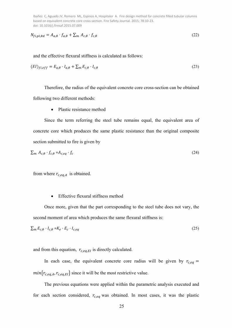
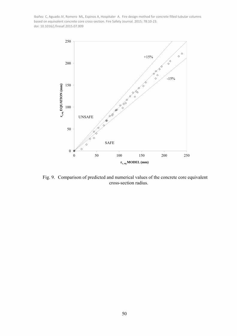
Fig. 9 shows the comparison between the values of , calculated by the model
and the ones given by the expression proposed. It can be observed that the predictions
given by the expression have a high accuracy, with a safe mean error of 1.09 (σ=0.22).
The error is calculated by:
1 , ,
, (27)
5.2. BUCKLING CORRECTION FACTOR
Once the equivalent concrete core cross-section can be calculated, the next steps
are executed. The relative slenderness at high temperatures is given by:
, , (28)
where is the elastic critical normal force calculated as follows:

Ibañez C, Aguado JV, Romero ML, Espinos A, Hospitaler A. Fire design method for concrete filled tubular columns
based on equivalent concrete core cross‐section. Fire Safety Journal. 2015; 78:10‐23.
doi: 10.1016/j.firesaf.2015.07.009
27
, (29)
In the calculation model here proposed, the value of the fire resistance of a CFT
column in axial compression is calculated as follows:
, , , (30)
where is the reduction coefficient for the relevant buckling mode given in EN 1994-1-
1 [25], which in this case corresponds to buckling curve “a”; and is the
buckling correction factor to account for the influence of second order effects at high
temperatures. As it can be observed, the simple method proposed employs the buckling
curve “a” for calculation. The development of a new buckling curve is not considered in
the method, just the adoption of a correction factor.
In order to define the shape of the buckling correction factor, the values of the
normal force given a thermo-mechanical parametric analysis executed using the fiber
model presented in [12] were used. The CFT column sections employed in the analysis
were the ones specified in section 4. All the specimens were assumed to have a
compressive strength of 30 MPa for the concrete and a yield strength of 355 MPa for
the steel. For each cross-section, different values of slenderness were considered (0.3,
0.5, 1, 1.5 and 2) and calculated according to EN 1994-1-1 [25]. Once more, analysis
results were obtained for the four standard fire resistance classes (R30, R60, R90 and
R120) for the 176 cases studied. In Table 3, the variables studied and the values
considered which set the simple method applicability limits can be found.
In the thermo-mechanical parametric analysis, the procedure to obtain the fire
buckling resistance of each column was the next. First, each one of the specimens was

Ibañez C, Aguado JV, Romero ML, Espinos A, Hospitaler A. Fire design method for concrete filled tubular columns
based on equivalent concrete core cross‐section. Fire Safety Journal. 2015; 78:10‐23.
doi: 10.1016/j.firesaf.2015.07.009
28
analyzed under different load levels to obtain the corresponding FRR. These applied
loads were defined as a percentage of the room temperature buckling axial resistance,
ranging from 0 to 90% to cover a wide range of FRR values.
Once the Nfi,Rd-FRR curve is obtained for each column, the fire buckling
resistance, Nfi,Rd, at R30, R60, R90 and R120 minutes is calculated by linear
interpolation.
The fiber model used for the parametric analysis performs a simple sequentially
coupled thermal–stress analysis [12]. Two steps can be differenced. First, a thermal
analysis is carried out to compute the temperature field of the columns by means of the
finite differences method here presented and subsequently, a mechanical problem is
solved to obtain the structural response. The specimen is loaded in the first calculation
step and the load remains constant during the whole analysis.
The geometric imperfection due to the manufacturing process of the columns was
taken into account by simulating the first buckling mode shape of a pinned–pinned
column which exhibits a sinusoidal shape. The value adopted was L/1000 which is used
by most of researchers and produces accurate results [12].
For each specimen analyzed, the buckling correction was calculated by:
, ,
, , , (31)
With the set of buckling correction factor data, a statistical study was
implemented. The possibility of assigning a unique value to the buckling correction
factor was rejected since the analysis showed that the data was strongly dependent on
the different geometrical variables ⁄ , ⁄ , ⁄ that play an important role in this

Ibañez C, Aguado JV, Romero ML, Espinos A, Hospitaler A. Fire design method for concrete filled tubular columns
based on equivalent concrete core cross‐section. Fire Safety Journal. 2015; 78:10‐23.
doi: 10.1016/j.firesaf.2015.07.009
29
problem. Therefore, an expression which is function of the different variables was
proposed. The equation is composed by the product of three partial coefficients:
/ / / (32)
Once the intensity of the effect that each variable has on the buckling correction
factor was studied by means of a correlation analysis, a multiple nonlinear regression
analysis was carried out. The shape proposed for each of the terms multiplying was:
/ ⁄
(33)
/ ⁄
(34)
/ / (35)
When the influence of the relative slenderness at room temperature on the
buckling correction factor was studied, it was detected the convenience of developing
two different buckling correction factors: one for the specimens with 0.5 and
another one for the cases with 0.5.
For cases with 0.5 (stub columns):
/ 4.16 4.208 ⁄ .
(36)
/ 0.13 9.8 ⁄ .
(37)
/ 266 0.26 / .
(38)
For cases with 0.5 (slender columns):
/ 0.72 0.008 ⁄ .
(39)

Ibañez C, Aguado JV, Romero ML, Espinos A, Hospitaler A. Fire design method for concrete filled tubular columns
based on equivalent concrete core cross‐section. Fire Safety Journal. 2015; 78:10‐23.
doi: 10.1016/j.firesaf.2015.07.009
30
/ 0.67 7.4 ⁄ .
(40)
/ 0.52 0.11 / .
(41)
Finally, the equations presented above are applied to all the cases covered in the
parametric analysis in order to obtain the values of the buckling resistance in fire
situation. For each specimen, the predicted value was compared to the numerical value
and the error was computed using the next expression:
, 1 , , , ,
, , (42)
In order to check the accuracy of the simple method proposed, the criteria of the
assessment proposal made by CEN-Horizontal Group Fire [24] were again adopted.
The mean value of the error is equal to 1.07 which lies on the safe side (σ=0.16).
In Fig. 9, the error is plotted for the different values of relative slenderness at room
temperature. According to CEN-Horizontal Group Fire [24], it can be observed that the
simplified method produces values whose deviations with respect to the model
predictions are concentrated above the 15% limits.
In Fig. 11 the comparison between predicted and numerical values of Nfi,Rd is
plotted. Due to the wide range of fire buckling resistances two graphs are provided,
being Fig. 11b an enlarged view of the shaded area marked in Fig. 11a.
This figure complements the information provided by Fig. 10 since it allows the
observation of the regression line and its coefficient of determination R2 as
recommended by CEN-Horizontal Group Fire [24].

Ibañez C, Aguado JV, Romero ML, Espinos A, Hospitaler A. Fire design method for concrete filled tubular columns
based on equivalent concrete core cross‐section. Fire Safety Journal. 2015; 78:10‐23.
doi: 10.1016/j.firesaf.2015.07.009
31
5.3. STEP BY STEP CALCULATION PROCEDURE
In order to clarify the use of the proposed calculation procedure, the step by step
method is described below:
1) Determine the effective length of the column, , the section factor ⁄
and the ⁄ ratio.
2) Calculate the steel tube temperature by eq. (14) and the radius of the
equivalent concrete core section , by eq. (26).
3) Obtain the cross-sectional plastic resistance using eq. (20) and temperature
dependent steel mechanical properties from EN 1993-1-2 [21] .
4) Calculate the effective flexural stiffness using eq. (21) and temperature
dependent steel mechanical properties from EN 1993-1-2 [21] .
5) Compute the Euler buckling load by means of eq. (29) and the relative
slenderness in fire using eq. (28).
6) Calculate the buckling reduction coefficient from buckling curve “a” as it
is indicated in EN 1994-1-1 [25].
7) Calculate the buckling correction factor by means of eq. (32)
8) Obtain the axial buckling load in the fire situation by means of eq. (30).
5.4. COMPARISON OF CALCULATED PREDICTIONS WITH TESTS
Predictions given by the proposed method were compared to experimental data
from actual fire tests. The calculation procedure here presented is valid for circular CFT
columns filled with unreinforced normal strength concrete and under axial load.
Therefore, only data from experimental programs that obey these conditions was
contrasted.
Ibañez C, Aguado JV, Romero ML, Espinos A, Hospitaler A. Fire design method for concrete filled tubular columns
based on equivalent concrete core cross‐section. Fire Safety Journal. 2015; 78:10‐23.
doi: 10.1016/j.firesaf.2015.07.009
32
For this purpose, both results of tests carried out by the authors [13] and data from
tests found in the literature [15] were used. A description of these tests can be found in
section 3 and more details in Table 1 and Table 2. For this validation, test data from
[14] cannot be employed since all the specimens included in this program were
eccentrically loaded.
The comparison in terms of axial buckling load is presented in Fig. 12 where it
can be observed that the accuracy of the proposed method is satisfactory and that its
predictions are generally conservative
6. DESIGN EXAMPLE
In this section, a case of CFT column fire design is included to exemplify the use
of the fire design method presented.
The unprotected CFT column used in this example is 3400 mm long, has an
external diameter of 193.7 mm and a wall steel tube thickness of 16 mm. The
compressive strength of the concrete core is 30 MPa and for steel, a yield strength of
355 MPa is considered.
In this example, the axial buckling load in the fire situation for a column placed in
an intermediate floor for a fire exposure time of 30 min (R30) is asked to be determined.
First, the geometric parameters are calculated:
0.5 0.5 3400 1700 (EN 1994-1-2 establishes that the buckling
length in fire of a column in an intermediate story is defined as 0.5 times the original
length)
⁄ 4⁄ 4 193.7⁄ 0.02065
⁄ 193.7 16⁄ 12.11
⁄ 1700 193.7 8.77⁄

Ibañez C, Aguado JV, Romero ML, Espinos A, Hospitaler A. Fire design method for concrete filled tubular columns
based on equivalent concrete core cross‐section. Fire Safety Journal. 2015; 78:10‐23.
doi: 10.1016/j.firesaf.2015.07.009
33
Next, the steel tube temperature is computed:
20 345 8 30 1 1 3.38 30 .
1 0.155 30 . 16 . 616.76 º
And also the , :
, 80.85 23 0.02065 . 10 30 . 58.55
For a steel tube temperature of 616.76 ºC, the reduction factors for the yield
strength , and the modulus of elasticity , of the steel are taken from table 3.2 of
EN-1994-1-2 by linear interpolation:
, . 0.4297 , . 0.2798
Once this is done, the cross-sectional plastic resistance and the effective flexural
stiffness can be calculated.
, , , ,
8932.2 0.4297 355 10769.7 30 1685640.11685.64
, , , 0.2798 210000 35542569.5
0.6 32836.6 9231981.14 2.2703 10
Next, the Euler buckling load and the relative slenderness of the equivalent
column can be calculated:
, ⁄ 2.2703 10 1700⁄ 7753274.35 7753.27

Ibañez C, Aguado JV, Romero ML, Espinos A, Hospitaler A. Fire design method for concrete filled tubular columns
based on equivalent concrete core cross‐section. Fire Safety Journal. 2015; 78:10‐23.
doi: 10.1016/j.firesaf.2015.07.009
34
, , ⁄ 1685.64 7753.27⁄ 0.466
According to EN 1994-1-1, the reduction coefficient obtained from buckling
curve “a” for the given relative slenderness is 0.934.
Finally, the buckling correction factor should be obtained by means of eq. (32). In
this case, for this column (with an initial room temperature relative slenderness of 0.74),
the partial terms are given by eq. (39)-(41):
/ / /
0.72 0.008 8.77 . 0.67 7.4 0.02065 . 0.52
0.11 12.11 . 0.3625
Therefore, the fire resistance to the column to axial compression for a fire
exposure time of R30 is:
, , , 0.934 0.3625 1685.64 570.48
7. SUMMARY AND CONCLUSIONS
On a first stage, this paper provided a set of practical expressions for obtaining the
cross-sectional temperatures of circular CFT columns. A realistic finite differences
thermal model for circular CFT columns with any type of infill was presented. The
consideration of the effects of the gap conductance at steel-concrete interface by
characterizing the separation layer by a thermal conductance was crucial and produced
much more realistic predictions than assuming perfect contact.
The thermal model was validated against experimental data and it showed
remarkably good agreement with tests results in terms of temperature versus time and
high accuracy when temperatures at time of failure were contrasted.

Ibañez C, Aguado JV, Romero ML, Espinos A, Hospitaler A. Fire design method for concrete filled tubular columns
based on equivalent concrete core cross‐section. Fire Safety Journal. 2015; 78:10‐23.
doi: 10.1016/j.firesaf.2015.07.009
35
With this model a thermal parametric analysis was performed and through the
subsequent statistical study the proposed equations were extracted. Equation predictions
were also compared to experimental results showing reasonable accuracy given the
irregularities that may arise when measuring temperatures during a test. These
expressions allow designers to compute easily the temperature distribution in the
composite section without the need of implementing complex thermal models.
The paper also proposed a design method for obtaining the fire resistance of
axially loaded circular CFT columns based on general rules of EN 1994-1-1. The
concept of room temperature equivalent concrete core cross-section was introduced and
used in the development of the simplified method where also a new buckling correction
factor was considered. Numerical results generated through an extensive thermo-
mechanical parametric analysis were used to carry out a multiple nonlinear regression
analysis and, as a result, the expression for the buckling correction factor was built.
The equations for temperature calculation as well as the one for obtaining the
buckling fire resistance were assessed following the guidelines included in CEN-
Horizontal Group Fire for checking the accuracy of simplified methods.
The simple method predictions were compared to experimental data and they
showed to be slightly conservative. In general, it can be said that the method produces
satisfactory values of the fire resistance.
ACKNOWLEDGEMENTS
The authors would like to express their sincere gratitude to the Spanish Ministry
of Economy and Competitivity for the help provided through the project BIA2012-
33144, and to the European Community for the FEDER funds.

Ibañez C, Aguado JV, Romero ML, Espinos A, Hospitaler A. Fire design method for concrete filled tubular columns
based on equivalent concrete core cross‐section. Fire Safety Journal. 2015; 78:10‐23.
doi: 10.1016/j.firesaf.2015.07.009
36
REFERENCES
[1] CEN. EN 1994-1-2, Eurocode 4: Design of composite steel and concrete structures,
Part 1.2: General rules - Structural fire design. Brussels, Belgium: Comité
Européen de Normalisation; 2005.
[2] Espinos A, Romero M, Hospitaler A. Advanced model for predicting the fire
response of concrete filled tubular columns. Journal of constructional steel research
2010; 66(8-9):1030-1046.
[3] Lu H, Zhao X, Han L. Fire behaviour of high strength self-consolidating concrete
filled steel tubular stub columns. Journal of constructional steel research 2009;
65(10-11):1995-2010.
[4] Wang ZH, Au SK, Tan KH. Heat transfer analysis using a Green’s function
approach for uniformly insulated steel members subjected to fire. Engineering
Structures 2005; 27(10): 1551-1562.
[5] Wang ZH, Tan KH. Green’s function solution for transient heat conduction in
concrete filled steel CHS subjected to fire. Engineering Structures 2006; 28(11):
1574-1585.
[6] Lie TT. Fire resistance of circular steel columns filled with bar-reinforced concrete.
Journal of Structural Engineering-ASCE 1994; 120(5):1489-1509.
[7] Dusinberre, G.M. Heat transfer calculations by finite differences. International
Textbook Co., Scranton, Pa. 1961.
[8] Espinos A., Romero M.L., Hospitaler A. Simple calculation model for evaluating
the fire resistance of unreinforced concrete filled tubular columns. Engineering
Structures 2012; 42: 231-244.

Ibañez C, Aguado JV, Romero ML, Espinos A, Hospitaler A. Fire design method for concrete filled tubular columns
based on equivalent concrete core cross‐section. Fire Safety Journal. 2015; 78:10‐23.
doi: 10.1016/j.firesaf.2015.07.009
37
[9] Yu M., Zha X., Ye J., Wang B. A unified method for calculating the fire resistance
of solid and hollow concrete filled steel tube columns based on average
temperature. Engineering Structures 2014; 71: 12-22.
[10] ISO (International Standards Organization). ISO 834: Fire resistance tests,
elements of building construction. Switzerland: International Standards
Organisation; 1980.
[11] CEN. EN 1991-1-2, Eurocode 1: Actions on structures, Part 1.2: General actions -
Actions on structures exposed to fire. Brussels, Belgium: Comité Européen de
Normalisation; 2002.
[12] Ibañez C., Romero M.L., Hospitaler A. Fiber beam model for fire response
simulation of axially loaded concrete filled tubular columns. Engineering
Structures 2013; 56: 182-193
[13] Romero M.L., Moliner V., Espinos A., Ibañez C., Hospitaler A. Fire behavior of
axially loaded slender high strength concrete filled tubular columns. Journal of
Constructional Steel Research 2011; 67: 1953-1965.
[14] Moliner V., Espinos A., Romero M.L., Hospitaler A. Fire behavior of eccentrically
loaded slender high strength concrete filled tubular columns. Journal of
Constructional Steel Research 2013. 83: 137-146.
[15] Lie TT, Chabot M. Experimental studies on the fire resistance of hollow steel
columns filled with plain concrete. Internal report No. 611. Ottawa, Canada:
Institute for Research in Construction, National Research Council of Canada
(NRCC); 1992.

Ibañez C, Aguado JV, Romero ML, Espinos A, Hospitaler A. Fire design method for concrete filled tubular columns
based on equivalent concrete core cross‐section. Fire Safety Journal. 2015; 78:10‐23.
doi: 10.1016/j.firesaf.2015.07.009
38
[16] ASTM. Standard ASTM E119-88: Standard methods of fire test of building
construction and materials. Philadelphia, Pa: American Society for Testing and
Materials; 1990.
[17] CEN. EN 1992-1-2, Eurocode 2: Design of concrete structures, Part 1.2: General
rules – Structural fire design. Brussels, Belgium: Comité Européen de
Normalisation; 2004.
[18] Kodur V.K.R, Sultan M.A. Effect of temperature on thermal properties of high-
strength concrete. Journal of Materials in Civil Engineering 2003; 15(2):101-107.
[19] Kodur V.K.R, Lie TT. Fire resistance of circular steel columns filled with fiber-
reinforced concrete. Journal of Structural Engineering-ASCE 1996; 122(7):776-
782.
[20] Lie TT, Kodur V.K.R. Effect of temperature on thermal and mechanical properties
of steel fiber-reinforced concrete. Internal report No. 695. Ottawa, Canada: Institute
for Research in Construction, National Research Council of Canada (NRCC);
1995.
[21] CEN. EN 1993-1-2, Eurocode 3: Design of steel structures, Part 1.2: General rules
– Structural fire design. Brussels, Belgium: Comité Européen de Normalisation;
2005.
[22] Ding J, Wang YC. Realistic modelling of thermal and structural behavior of
unprotected concrete filled tubular columns in fire. Journal of Constructional Steel
Research 2008; 64:1086-1102.
[23] Wickström, U. 1986, "A very simple method for estimating temperature in fire
exposed concrete structures." Fire Technology Technical report SP-RAPP 1986,
46, Swedish National Testing Institute, pp. 186-194.

Ibañez C, Aguado JV, Romero ML, Espinos A, Hospitaler A. Fire design method for concrete filled tubular columns
based on equivalent concrete core cross‐section. Fire Safety Journal. 2015; 78:10‐23.
doi: 10.1016/j.firesaf.2015.07.009
39
[24] CEN-TC-250-Horizontal Group Fire. Document 99/130. Eurocodes-Fire Parts.
Proposal for a methodology to check the accuracy of assessment methods..
November 1999
[25] CEN. EN 1994-1-1, Eurocode 4: Design of composite steel and concrete structures,
Part 1.1: General rules and rules for buildings. Brussels, Belgium: Comité
Européen de Normalisation; 2004.
Ibañez C, Aguado JV, Romero ML, Espinos A, Hospitaler A. Fire design method for concrete filled tubular columns
based on equivalent concrete core cross‐section. Fire Safety Journal. 2015; 78:10‐23.
doi: 10.1016/j.firesaf.2015.07.009
40
LIST OF FIGURE CAPTIONS
Fig. 1. CFT column. Discretization of the section for thermal analysis.
Fig. 2. Detail of the section. Gap conductance at steel-concrete boundary.
Fig. 3. Comparison between measured and thermal model predicted temperatures with different steel-concrete boundary model: gap conductance versus perfect contact.
Fig. 4. Comparison of temperatures at failure.
Fig. 5. Temperature profile of a longitudinal section of a CFT column.
Fig. 6. Comparison of the predicted temperatures given by the equations proposed and the values generated in the thermal parametric analysis.
Fig. 7. Comparison of test temperatures with temperatures calculated by thermal model and proposed equations for one of the specimens analyzed (C-09).
Fig. 8. Cross-section schemes for CFT columns used for calculation.
Fig. 9. Comparison of predicted and numerical values of the concrete core equivalent cross-section radius.
Fig. 10. Relative error. Comparison between the results of the calculation proposal and the numerical simulations.
Fig. 11. Comparison between the proposed method and numerical simulations.
Fig. 12. Comparison between predicted loads and tests loads.

Ibañez C, Aguado JV, Romero ML, Espinos A, Hospitaler A. Fire design method for concrete filled tubular columns
based on equivalent concrete core cross‐section. Fire Safety Journal. 2015; 78:10‐23.
doi: 10.1016/j.firesaf.2015.07.009
41
LIST OF TABLE CAPTIONS
Table 1. Tests by the authors [13] [14] .
Table 2. Tests from experimental programs found in literature [15].
Table 3. Studied variables in the thermo-mechanical parametric analysis and adopted values.

Ibañez C, Aguado JV, Romero ML, Espinos A, Hospitaler A. Fire design method for concrete filled tubular columns
based on equivalent concrete core cross‐section. Fire Safety Journal. 2015; 78:10‐23.
doi: 10.1016/j.firesaf.2015.07.009
42
Fig. 1. CFT column. Discretization of the section for thermal analysis.
∆2
∆2
∆
∆

Ibañez C, Aguado JV, Romero ML, Espinos A, Hospitaler A. Fire design method for concrete filled tubular columns
based on equivalent concrete core cross‐section. Fire Safety Journal. 2015; 78:10‐23.
doi: 10.1016/j.firesaf.2015.07.009
43
Pm,steel P1Pm,conc PM1+1 PM1
(concrete)PM1-1
(steel)
Gap conductance at steel-concrete boundary
Node duplicated at steel-concrete
boundary
Fig. 2. Detail of the section. Gap conductance at steel-concrete boundary.

Ibañez C, Aguado JV, Romero ML, Espinos A, Hospitaler A. Fire design method for concrete filled tubular columns
based on equivalent concrete core cross‐section. Fire Safety Journal. 2015; 78:10‐23.
doi: 10.1016/j.firesaf.2015.07.009
44
(a) Column C-159-6-3-80-0-20
(b) Column C-31
Fig. 3. Comparison between measured and thermal model predicted temperatures with different steel-concrete boundary model: gap conductance
versus perfect contact.

Ibañez C, Aguado JV, Romero ML, Espinos A, Hospitaler A. Fire design method for concrete filled tubular columns
based on equivalent concrete core cross‐section. Fire Safety Journal. 2015; 78:10‐23.
doi: 10.1016/j.firesaf.2015.07.009
45
(a) Temperature predicted by the model vs. test temperature
(b) Temperature predicted by the equations vs. test temperature
Fig. 4. Comparison of temperatures at failure.
0
200
400
600
800
1000
1200
0 200 400 600 800 1000 1200
TF
RR
, MO
DE
L (
ºC)
TFRR ,TEST (ºC)
SAFE
UNSAFE
+15%
-15%
0
200
400
600
800
1000
1200
0 200 400 600 800 1000 1200
TF
RR
, EQ
UA
TIO
N (
ºC)
TFRR, TEST (ºC)
Equation
Equation reg. line(y=1.20x-157.71)
SAFE
UNSAFE
+15%
-15%R2=0.964

Ibañez C, Aguado JV, Romero ML, Espinos A, Hospitaler A. Fire design method for concrete filled tubular columns
based on equivalent concrete core cross‐section. Fire Safety Journal. 2015; 78:10‐23.
doi: 10.1016/j.firesaf.2015.07.009
46
Fig. 5. Temperature profile of a longitudinal section of a CFT column.
Δθ
Δθ
θ
θ
θ
θ
Position

Ibañez C, Aguado JV, Romero ML, Espinos A, Hospitaler A. Fire design method for concrete filled tubular columns
based on equivalent concrete core cross‐section. Fire Safety Journal. 2015; 78:10‐23.
doi: 10.1016/j.firesaf.2015.07.009
47
(a) Steel tube temperatures
(b) Concrete core temperatures
Fig. 6. Comparison of the predicted temperatures given by the equations proposed and the values generated in the thermal parametric analysis.
R² = 0.991
0
200
400
600
800
1000
1200
0 200 400 600 800 1000 1200
Tem
per
atu
res,
EQ
UA
TIO
N (
ºC)
Temperatures, MODEL (ºC)
Equation
Equation reg. line(y=0.9589x+28.186)
UNSAFE
SAFE
+15%
-15%
R² = 0.9797
0
200
400
600
800
1000
1200
0 200 400 600 800 1000 1200
Tem
pera
ture
s, E
QU
AT
ION
(ºC
)
Temperatures, MODEL (ºC)
Equation
Equation reg. line(y=0.9621x+44.398)
SAFE
UNSAFE
+15%
-15%

Ibañez C, Aguado JV, Romero ML, Espinos A, Hospitaler A. Fire design method for concrete filled tubular columns
based on equivalent concrete core cross‐section. Fire Safety Journal. 2015; 78:10‐23.
doi: 10.1016/j.firesaf.2015.07.009
48
Fig. 7. Comparison of test temperatures with temperatures calculated by thermal model and proposed equations for one of the specimens analyzed (C-09).

Ibañez C, Aguado JV, Romero ML, Espinos A, Hospitaler A. Fire design method for concrete filled tubular columns
based on equivalent concrete core cross‐section. Fire Safety Journal. 2015; 78:10‐23.
doi: 10.1016/j.firesaf.2015.07.009
49
(a) Cross-section adopted by the proposed method. Striped area represents the equivalent concrete core
cross-section at room temperature given by rc,eq
(b) Layer discretization of the cross-section according to EN 1994-1-2 [1] for design
purposes.
Fig. 8. Cross-section schemes for CFT columns used for calculation.
,
, , ,
, , , ,
1 2 …
Ibañez C, Aguado JV, Romero ML, Espinos A, Hospitaler A. Fire design method for concrete filled tubular columns
based on equivalent concrete core cross‐section. Fire Safety Journal. 2015; 78:10‐23.
doi: 10.1016/j.firesaf.2015.07.009
50
Fig. 9. Comparison of predicted and numerical values of the concrete core equivalent cross-section radius.
0
50
100
150
200
250
0 50 100 150 200 250
r c,e
qE
QU
AT
ION
(m
m)
rc, eq MODEL (mm)
+15%
-15%
SAFE
UNSAFE

Ibañez C, Aguado JV, Romero ML, Espinos A, Hospitaler A. Fire design method for concrete filled tubular columns
based on equivalent concrete core cross‐section. Fire Safety Journal. 2015; 78:10‐23.
doi: 10.1016/j.firesaf.2015.07.009
51
Fig. 10. Relative error. Comparison between the results of the calculation proposal and the numerical simulations.
0
0,5
1
1,5
2
0 0,5 1 1,5 2
UNSAFE
-15%
SAFE
+15%

Ibañez C, Aguado JV, Romero ML, Espinos A, Hospitaler A. Fire design method for concrete filled tubular columns
based on equivalent concrete core cross‐section. Fire Safety Journal. 2015; 78:10‐23.
doi: 10.1016/j.firesaf.2015.07.009
52
(a) Proposed method predictions vs. model results
(b) Enlarged view of shaded area in Fig11 a.
Fig. 11. Comparison between the proposed method and numerical simulations.
R² = 0,9868
0
2000
4000
6000
8000
0 2000 4000 6000 8000
Nf i,
Rd
PR
ED
ICT
ED
(k
N)
Nfi,Rd MODEL (kN)
Proposed method
Prediction reg. line(y=0.9225x-10.584)
UNSAFE+15%
-15%
SAFE
see enlarged view in Fig. 11b
0
500
1000
1500
2000
0 500 1000 1500 2000
Nf i,
Rd
PR
ED
ICT
ED
(k
N)
Nfi,Rd MODEL (kN)
UNSAFE
+15%
-15%
SAFE

Ibañez C, Aguado JV, Romero ML, Espinos A, Hospitaler A. Fire design method for concrete filled tubular columns
based on equivalent concrete core cross‐section. Fire Safety Journal. 2015; 78:10‐23.
doi: 10.1016/j.firesaf.2015.07.009
53
Fig. 12. Comparison between predicted loads and tests loads.
R² = 0,8442
0
200
400
600
800
1000
1200
0 200 400 600 800 1000 1200
Pre
dict
ed L
oad
(k
N)
Test Load (kN)
Tests by theauthors [13]Tests fromliterature [15]Tests reg. line(y=0.917x-91.282)
SAFE
UNSAFE
+15%
-15%

Ibañez C, Aguado JV, Romero ML, Espinos A, Hospitaler A. Fire design method for concrete filled tubular columns
based on equivalent concrete core cross‐section. Fire Safety Journal. 2015; 78:10‐23.
doi: 10.1016/j.firesaf.2015.07.009
54
Table 1. Tests by the authors [13][14] .
Column D t fy fc N µ
FRR TestFRR
T
MODELFRRT
MODELFRR
TestFRRFRR T
TT
Name (mm) (mm) (N/mm2) (N/mm2) (kN) (min) (ºC) (ºC)
C159-6-3-30-0-20
159
6
337.80
35.75
198
0.2
42
850
810
1.05
C159-6-3-30-0-40 159 6 337.80 28.55 396 0.4 25 654 656 1.00
C159-6-3-30-0-60 159 6 337.80 34.05 594 0.6 14 583 462 1.26
C159-6-3-80-0-20 159 6 341.40 71.14 335 0.2 37 756 761 0.99
C159-6-3-80-0-40 159 6 341.40 69.00 670 0.4 11 424 380 1.12
RC159-6-3-30-0-20 159 6 337.80 23.90 229 0.2 43 768 816 0.94
RC159-6-3-30-0-40 159 6 337.80 30.00 458 0.4 30 726 711 1.02
RC159-6-3-30-0-60 159 6 337.80 33.70 687 0.6 13 444 436 1.02
RC159-6-3-80-0-20 159 6 337.80 69.03 343 0.2 64 913 900 1.01
RC159-6-3-80-0-40 159 6 337.80 77.00 720 0.4 18 496 551 0.90
FC159-6-3-30-0-20 159 6 337.80 28.30 198 0.2 36 751 739 1.02
FC159-6-3-30-0-40 159 6 334.40 26.70 396 0.4 22 723 594 1.22
FC159-6-3-80-0-20 159 6 337.80 93.62 335 0.2 35 763 733 1.04
FC159-6-3-80-0-40 159 6 334.40 90.16 670 0.4 15 481 461 1.04
C159-6-3-30-20-20 159 6 332.03 35.83 169 0.2 33 734 743 0.99
C159-6-3-30-20-40 159 6 332.03 42.17 337 0.4 17 552 538 1.03
C159-6-3-30-50-20 159 6 332.03 73.70 272 0.2 31 658 735 0.90
C159-6-3-30-50-40 159 6 343.63 74.64 544 0.4 24 623 667 0.93
C159-6-3-90-20-20 159 6 343.63 30.5 126 0.2 35 746 754 0.99
C159-6-3-90-20-40 159 6 365.65 38.25 253 0.4 13 435 438 0.99
C159-6-3-90-50-20 159 6 365.65 79.13 194 0.2 31 720 733 0.98
C159-6-3-90-50-40 159 6 365.65 98.32 388 0.4 17 475 539 0.88
RC159-6-3-30-20-20 159 6 357.22 39.00 180 0.2 49 834 865 0.96
RC159-6-3-30-20-40 159 6 357.22 40.38 360 0.4 25 622 675 0.92
RC159-6-3-30-50-20 159 6 357.22 93.67 264 0.2 40 792 814 0.97
RC159-6-3-30-50-40 159 6 386.38 96.00 528 0.4 21 634 623 1.02
RC159-6-3-90-20-20 159 6 386.38 31.00 140 0.2 49 841 835 1.01
RC159-6-3-90-20-40 159 6 386.38 39.50 280 0.4 25 718 675 1.06
RC159-6-3-90-50-20 159 6 315.22 92.97 204 0.2 41 779 802 0.97
RC159-6-3-90-50-40 159 6 315.22 91.87 407 0.4 17 503 541 0.93
FC159-6-3-30-20-20 159 6 315.22 34.67 169 0.2 32 723 713 1.01
FC159-6-3-30-20-40 159 6 337.77 31.50 337 0.4 18 569 518 1.10
FC159-6-3-30-50-20 159 6 337.77 87.12 272 0.2 31 690 710 0.97
FC159-6-3-30-50-40 159 6 337.77 83.04 544 0.4 25 646 644 1.00
FC159-6-3-90-20-20 159 6 318.64 33.00 126 0.2 24 564 599 0.94
FC159-6-3-90-20-40 159 6 318.64 37.65 253 0.4 14 425 407 1.04
FC159-6-3-90-50-20 159 6 318.64 96.99 194 0.2 30 653 685 0.95
FC159-6-3-90-50-40 159 6 326.39 92.78 388 0.4 16 434 458 0.95
Mean 1.00
Standard deviation 0.01

Ibañez C, Aguado JV, Romero ML, Espinos A, Hospitaler A. Fire design method for concrete filled tubular columns
based on equivalent concrete core cross‐section. Fire Safety Journal. 2015; 78:10‐23.
doi: 10.1016/j.firesaf.2015.07.009
55
Table 2. Tests from experimental programs found in literature [15].
Column D t fy fc N µ
FRR TestFRR
T MODELFRR
T
MODELFRR
TestFRRFRR T
TT
Name (mm) (mm) (N/mm2) (N/mm2) (kN) (min) (ºC) (ºC)
C-02
141.3
6.55
350
33.1 (sil)
110
0.12
55
852
855
1.00
C-04 141.3 6.55 350 31.0 (sil) 131 0.14 57 844 862 0.98
C-05 168.3 4.78 350 32.7 (sil) 150 0.16 76 913 917 1.00
C-06 168.3 4.78 350 32.7 (sil) 150 0.19 60 878 875 1.00
C-08 168.3 4.78 350 35.5 (sil) 218 0.23 56 896 882 1.02
C-09 168.3 6.35 350 35.4 (sil) 150 0.13 81 923 928 0.99
C-11 219.1 4.78 350 31.0 (sil) 492 0.35 80 924 923 1.00
C-13 219.1 4.78 350 32.3 (sil) 384 0.27 102 960 961 1.00
C-15 219.1 8.18 350 31.9 (sil) 525 0.28 73 906 903 1.00
C-17 219.1 8.18 350 31.7 (sil) 525 0.26 82 934 921 1.01
C-20 273.1 5.56 350 28.6 (sil) 574 0.26 112 959 961 1.00
C-21 273.1 5.56 350 29.0 (sil) 525 0.23 133 986 984 1.00
C-22 273.1 5.56 350 27.2 (sil) 1000 0.45 70 861 871 0.99
C-23 273.1 12.70 350 27.4 (sil) 525 0.13 143 1016 996 1.02
C-31 141.3 6.55 300 30.2 (cal) 80 0.09 82 944 937 1.01
C-32 141.3 6.55 300 34.8 (cal) 143 0.17 64 911 896 1.02
C-34 219.1 4.78 300 35.4 (cal) 500 0.36 111 967 971 1.00
C-35 219.1 4.78 300 42.7 (cal) 560 0.36 108 955 965 0.99
C-37 219.1 8.18 350 28.7 (cal) 560 0.25 102 947 955 0.99
C-40 273.1 6.35 350 46.5 (cal) 1050 0.37 106 946 959 0.99
C-41 273.1 6.35 350 50.7 (cal) 1050 0.37 76 901 905 1.00
C-42 273.1 6.35 350 55.4 (cal) 1050 0.35 90 926 933 0.99
C-44 273.1 6.35 350 38.7 (cal) 715 0.27 178 1035 1045 0.99
Mean 1.00
Standard deviation 0.08

Ibañez C, Aguado JV, Romero ML, Espinos A, Hospitaler A. Fire design method for concrete filled tubular columns
based on equivalent concrete core cross‐section. Fire Safety Journal. 2015; 78:10‐23.
doi: 10.1016/j.firesaf.2015.07.009
56
Table 3. Studied variables in the thermo-mechanical parametric analysis and adopted values.
Studied
variablesD
(mm) t
(mm) R
(min)
Adopted values
139.7
3.2; 12.5
0.3; 0.5; 1; 1.5; 2
30; 60; 90; 120
193.7 5; 16 0.3; 0.5; 1; 1.5; 2
273 5; 16 0.3; 0.5; 1; 1.5
323.9 6.3; 16 0.3; 0.5; 1
406.4 8; 16 0.3; 0.5; 1
508 10; 16 0.3; 0.5


![City Research Online · element modelling of hollow and concrete-filled stainless steel tubular columns under lateral static or impact loading. Wang et al. (2013)[11] reported the](https://img.dokumen.tips/doc/110x75/607392728faf4c647e7152d1/city-research-online-element-modelling-of-hollow-and-concrete-filled-stainless-steel.jpg)