Embed Size (px)
DESCRIPTION
http://www.seipub.org/CE/paperInfo.aspx?ID=2841 In the present research, experimental studies have been devoted to investigating the behavior of self-compacting Concrete Filled Steel Tube (CFST) stub columns strengthened by Carbon Fiber Reinforced Polymer (CFRP) laminates. A total of 28 stub columns under monotonic compression load were tested in order to discover the best configuration of the CFRP for confined column system, fourteen specimens with circular cross-sections (100x300) mm and another fourteen specimens with square cross-sections (100x100x300) mm, and each fourteen specimens can be classified into three categories: three hollow steel tube columns, three plain SCC columns, and eight SCC filled steel tube columns. The experimental results indicated that the use of CFRP laminates to strengthen the CFST has a significant effect on the overall behavior of CFST such as enhancement on its strength and ductility. Also the CFRP confinement delays local buckling of steel tube
Citation preview

Construction Engineering (CE) Volume 1 Issue 2, July 2013 www.seipub.org/ce
37
Experimental Investigation on Behavior of SCC Filled Steel Tubular Stub Columns Strengthened with CFRP Nameer A. Alwash1 and Hayder I. AL-Salih2 1Professor, Ph.D. Structural Engineering, Department of Civil Engineering, Babylon University, Iraq; 2 M.Sc. Structural Engineering, Department of Civil Engineering, Babylon University, Iraq; 2 [email protected]
Abstract
In the present research, experimental studies have been devoted to investigating the behavior of self-compacting Concrete Filled Steel Tube (CFST) stub columns strengthened by Carbon Fiber Reinforced Polymer (CFRP) laminates. A total of 28 stub columns under monotonic compression load were tested in order to discover the best configuration of the CFRP for confined column system, fourteen specimens with circular cross-sections (100x300) mm and another fourteen specimens with square cross-sections (100x100x300) mm, and each fourteen specimens can be classified into three categories: three hollow steel tube columns, three plain SCC columns, and eight SCC filled steel tube columns. The experimental results indicated that the use of CFRP laminates to strengthen the CFST has a significant effect on the overall behavior of CFST such as enhancement on its strength and ductility. Also the CFRP confinement delays local buckling of steel tube, prevents a sudden strength reduction caused by the local buckling of the steel tube, and increases lateral confinement of the concrete core. It is found that the best configuration of CFRP tubes system is transverse CFRP tube for circular hollow steel tube columns, circular plain concrete columns, circular concrete filled steel tube columns and square plain concrete column with a percent of increase in ultimate load of (31.1%, 254.3%, 43.4%, and 101%) respectively, and longitudinal CFRP tube for square hollow steel tube columns and square concrete filled steel tube columns with a percent of increase in ultimate load of (30.5% and 25.66%) respectively. While the best configuration of CFRP rings system is four rings of 37.5mm width for both circular and square concrete filled steel tube columns with a percent of increase in ultimate load of (24.15% and 17.1%) respectively.
Keywords
Composite Columns, Concrete Filled Steel Tube, Strengthening of Stub Columns, Carbon Fiber Reinforced Polymer, Self Compact Concrete
Introduction
Recently many different types of composite material systems have been widely applied to concrete column design to provide better performance in terms of high strength, stiffness, ductility and seismic resistance. Some of these composite columns are fully encased steel sections, partially encased steel sections and concrete filled steel tube. Among them, the concrete-filled steel tube (CFST) column system has turned out to be one of the most successful composite concrete column systems. The CFST column is a composite material system which employs the various advantages of different materials and combines them together in a steel tube column which is filled-in with concrete. CFST columns have a number of distinct advantages over equivalent steel, reinforced concrete, or steel- reinforced concrete columns. Steel columns have the advantages of high tensile strength and ductility, while concrete columns have the advantages of high compressive strength and stiffness. Composite columns combine steel and concrete, resulting in a column that has the beneficial qualities of both materials. The steel tube serves as a form of casting the concrete, which reduces construction cost. No other reinforcement is needed since the tube acts as longitudinal and lateral reinforcement for the concrete core. In addition, the location of the steel and the concrete in the cross-section optimizes the strength and stiffness of the section. In the CFST the steel lies at the outer perimeter where it performs most effectively in tension and in resisting bending moment. Similarly, the stiffness of the concrete-filled column is greatly enhanced because the steel is situated farthest from the centroid, where it makes the greatest contribution to the moment of inertia. The continuous confinement provided to the concrete core by the steel tube enhances the core’s strength and ductility. The concrete core delays the local buckling of

www.seipub.org/ce Construction Engineering (CE) Volume 1 Issue 2, July 2013
38
the steel tube by preventing inward buckling, while steel tube prevents the concrete from spalling.
It has been expected that the confined CFST (CCFST) column system can be an excellent remedy for the problems of the conventional CFST system by providing additional transverse confinement for the composite materials. As a result, the CFST column system with the CFRP confinement will become a simple solution to change the mechanical behavior of CFST in order to enhance its strength and ductility, and remedy deformability without significant strength reduction in composite materials.
In the constructed structures of CFST, such as some multistory buildings and skyscrapers, hollow steel tubes are usually fixed first with steel beams, bracing structures and so on, and then the concrete is pumped into the hollow steel tubes after having established several or even dozens of stories. Consequently, in recent years, the use of self-compacting concrete, in such kinds of columns has been of interest to many structural engineers. Due to its rheological properties, the disadvantage of vibration can be eliminated while still obtaining good consolidation. Apart from reliability and constructability, advantages such as elimination of noise in processing plants, and the reduction of construction time and labor cost can be achieved. It is expected that SCC will be used in concrete-filled HSS columns in the future because of its good performance. However, the composite members are susceptible to the influence of concrete compaction.
Experimental Program
General
In this work, mild steel tubes used in the construction of the specimens were manufactured in Turkey, the steel tube sections were cut from the original 6 m steel tube and the ends machined to meet required length have dimensions of cross section (100x100) mm and height of 300 mm with thickness of 2mm for square section as well as diameter of (100) mm and height of (300) mm with thickness of 2mm for circular sections. The CFRP laminate is used to strengthen the hollow steel tube columns, plain Self Compacting Concrete (SCC) columns, and SCC filled steel tube columns. A total of 28 stub columns under monotonic compression load was tested in order to discover the best configuration of the CFRP for confining column system, fourteen specimens with circular cross-sections, while another fourteen specimens with square cross-sections, each of which can be classified into three categories: three hollow steel tube columns, three plain SCC columns, and eight SCC filled steel tube columns.
In order to identify the test models with different cross section and strengthening schemes, the following designation system is used:
• Cross section: (Sqr.) for square cross section, (Cir.) for circular
Nomenclature
bs Width of square column (mm)
ds Diameter of circular column (mm)
L Length of column (mm)
T Thickness of steel tube (mm)
Ec Modulus of elasticity of concrete (MPa)
Es Modulus of elasticity of steel(MPa)
Fc Compressive strength of concrete cylinder(MPa)
Fcu Compressive strength of concrete cube (MPa)
Ft Uniaxial tensile strength of concrete(MPa)
Fr Modulus of rupture (MPa)
Fct Splitting tensile strength of concrete (MPa)
Fy Yield stress of steel(MPa)
Fu Ultimate strength of steel (MPa)
SP Superplasticizer
G51 Glenium51
CFRP Carbon Fiber Reinforced Polymer
CFST Concrete-Filled Steel Tube
CFT Concrete-Filled Tube
CHS Circular Hollow Section
FRP Fiber Reinforced Polymer
HRWRA High Range Water Reducing Agent
HSS Hollow Structural Steel
LSP Limestone Powder
RHS Rectangular Hollow Section
SCC Self-Compacting Concrete
SHS Square Hollow Section
W/C Water-Cement ratio
W/P Water/Powder,

Construction Engineering (CE) Volume 1 Issue 2, July 2013 www.seipub.org/ce
39
• Type of section: (Hol.) for hollow steel tube column, (Pla.) plain concrete column, (Fil.) for filled steel tube column
• CFRP strengthening configuration: (T) for transverse CFRP strengthening , (L) for longitudinal CFRP strengthening , ( ) for
inclined CFRP strengthening, (Rin.) for CFRP rings.
• CFRP rings: (1Rin.) for one ring of 150mm, (2Rin.) for two rings of 75mm, (3Rin.) for three rings of 50mm, (4Rin.) for four rings of 37.5mm.
Figure 1 and Figure 2 show strengthening system for circular and square columns respectively.
Materials Properties
1) Steel
Mild steel tubes used in the construction of the specimens were manufactured in Turkey, commercially known "Toscelik". The tensile tests were conducted on three steel coupons cut from the original steel tubes according to ASTM A 370-05. Each tensile specimen was cut at 90 a way from the weld seam of the virgin steel. The specimens are tested in a tensile machine of 50 kN in capacity. The measured properties of the steel tubes obtained from these tests are shown in Figure 3. and Table1.
TABLE 1 MECHANICAL PROPERTIES OF STEEL
Thickness(mm) Yield Strength(MPa) Ultimate Strength (MPa) Elastic E-Modulus (GPa) Elongation Percentage (%) 2 355 414 200 18
FIG 1 STRENGTHENING SYSTEM FOR CIRCULAR COLUMNS
FIG 2 STRENGTHENING SYSTEM FOR SQUARE COLUMNS

www.seipub.org/ce Construction Engineering (CE) Volume 1 Issue 2, July 2013
40
FIG 3 STRESS STRAIN CURVE OF STEEL TUBES
2) CFRP
When loaded in tension, CFRP does not exhibit any plastic behavior (yield) before rupture. Sika wrap® Hex-230C (Unidirectional mid strength carbon fibers) was used to strengthen. The mechanical properties of CFRP laminate according to manufacturing specifications of Sika Company are shown in Table 2.
3) Epoxy Adhesive Properties
The most suitable adhesive material with CFRP laminate is Sikadur®-330. The adhesive type consists of two compounds, compound A (white colure) and compound B (grey colure). The main properties as supplied by the manufacturer are shown in Table 3.
4) Mixture of SCC
Self-compacting concrete (SCC) is an innovative concrete that does not require vibration for placing and compaction. It is able to flow under its own weight, completely filling formwork and achieving
full compaction, even in the presence of congested reinforcement. The hardened concrete is dense, homogeneous and has the same engineering properties and durability as traditional vibrated concrete.
The adopted mix design of SCC was based on the European Guidelines for Self Compacting Concrete (2005), and to verify the criteria on filling ability, passability and segregation resistance, laboratory trials (trial mixes) must be done, and then adjustments to the mix composition were made until all requirements were fulfilled as well as satisfactory self-compactability was gained through evaluating fresh concrete tests. The details of the adopted mix are shown in Table 4, while the fresh properties of the SCC mixture were shown in Table 5. The maximum size of the coarse aggregate was 14 mm. and in order to increase the slump and make the concrete easier to work, one of a new generation of superplasticizers (High Range Water Reducing Agent) designed for the production of SCC (Glenium 51 (G51)) was added in the concrete mix.
TABLE 2 TECHNICAL PROPERTIES OF CFRP LAMINATE
Properties Tensile Strength (MPa) Tensile E-Modulus(GPa) Elongation at break (%) Width (mm) Thickness (mm)
Sika Wrap Hex-230C 4300 234 1.8 60 0.131
TABLE 3 TECHNICAL PROPERTIES OF EPOXY
Properties Tensile Strength (MPa)
Tensile E-Modulus (GPa)
Elongation at break (%) Open time, min Full cure, days Mixing
ratio
Sikadur-330 30 4.5 0.9 30 (at +35oC) 7 (at +35oC) 4:1 (as A:B)
TABLE 4 DETAILS OF MIX PROPORTION
Materials Cement(Kg/m3) Gravel(Kg/m3) Sand (Kg/m3)
Limestone Powder(Kg/m3) Water(l/m3) G 51
(l/m3) W/P W/C
Amount 340 900 870 85 190 4.76 0.447 0.558

Construction Engineering (CE) Volume 1 Issue 2, July 2013 www.seipub.org/ce
41
TABLE 5 THE FRESH PROPERTIES OF THE SCC MIXTURE
Characteristic Test Method Mesured Value Results Flowability Slump-flow test Total speared 750 mm
Viscosity T
500 Slump-flow test Flow time T500 4.1 Sec
V-funnel test Flow time Tv 6.9 Sec Passingability L-box test Passing ratio 0.916
Preparation of Models
1) Casting and Curing
The steel tubes sections were cut from the original 6 m steel tube and the ends were machined to meet required length. The insides of the tubes were wire brushed to remove any rust and loose debris. The deposits of grease and oil, if any, were cleaned away too. One end of each tube was covered by aluminum foil to prevent any seepage during concrete pouring, and then the tubes were placed upright with the covered end on a leveled white board to ensure stability during concrete pouring.
Every fourteen models was cast with one batch of self-compacting concrete; the same with each fourteen models the cubes, cylinders and prisms were cast to determine the properties of the hardened concrete.
The concrete filled in one layer was kept away from any vibration to ensure self-compacting.
(The level of concrete was some higher than that of
the steel tube end and it was ground to the same height of that of the steel tube after hardened by electrical hand grinding, and then a mixed epoxy was used to treat the problem of imperfections of grinding so that the concrete surface was flush with the steel tube at the top, which was to ensure that the load was applied evenly across the whole cross section simultaneously).
The models were placed upright to air-dry, and all loose mortar was removed from the top surface of the hardened concrete after 1 day, then the curing of CFST was done by sealing the models (and half number of cubes, all cylinders and all prisms ) with polyethylene sheets , after wetting the top surface in order to avoid shrinkage of concrete. The remaining half numbers of cubes were cured by the immergence in water in order to compare the effect of curing condition on compressive strength of concrete. Figure 4 shows casting and curing processes and the Table 6 shows the mechanical properties of hardened concrete.
TABLE 6 MECHANICAL PROPERTIES OF HARDENED CONCRETE
Ec (GPa) fr (MPa) f΄c (MPa) fcu (MPa) Mechanical properties
Cure 2 Cure 1 22.1 3.6 24.2 30.4 31.5 Square models 21.6 3.0 23.5 28.8 29.7 Circular models
Cure1: cured by immerging in water (for 28 days) Cure 2: sealing the models with polyethylene sheets, after wetting the top surface (for 28 days)
FIG. 4 CASTING AND CURING PROCESSES
2) Surface Preparation
The bond between the FRP and the surface is one of the most important parameters in the strengthening systems; and proper bond ensures that the force carried by the structural member is transferred effectively to the FRP.
Surface preparation of the steel tube was undertaken prior to bonding of the CFRP sheets, so before applying CFRP, the surface of the tubes was wire brushed to remove any rust and loose debris, and the deposits of grease and oil, if any, were cleaned away too.

www.seipub.org/ce Construction Engineering (CE) Volume 1 Issue 2, July 2013
42
After that, surface was roughened by sand blasting to enhance the bond between the steel and CFRP, and then the dust was cleaned using air blower and the faces were wiped using acetone.
Surface preparation of the concrete model was done by grinding the concrete surface by means of electrical hand grinder to remove the weak surface, rounded the edge of the model (approximately 15 mm) to prevent stress concentration in the CFRP sheets. And then clean and remove the dust from the concrete surface using air blower.
3) Application of CFRP Composites
1) Marking the dimensions (if any) on the model.
2) Cut the CFRP into the required lengths.
3) Mix part A and B together according to manufacturer technical data with a slow speed electrical drill till it becomes grey in color.
4) Apply a thin layer of mixed epoxy on the model surface (approximately 1.5 mm).
This will impregnate the carbon fiber sheet after they are placed on the model.
5) Apply a coat of mixed epoxy on the clean carbon fiber sheet.
6) Place carbon fiber sheet on the surface of model which was previously coated with epoxy.
7) Flatten it repeatedly (by a rubber roller or by trowel) with direction of the sheet in order to remove air bubble and let epoxy immerge in the sheet.
8) The finishing end of a sheet overlapped the starting end by 150 mm.
After the CFRP installation was completed, a mixed epoxy was used to treat the problem of imperfections of grinding on the column end so that the concrete surface was flush with the steel tube at the top. This was to ensure that the load was applied evenly across the whole cross section simultaneously. After that, the wrapped models were left to cure in the laboratory environment at room temperature for about one month before testing. Figure 5 shows the application of CFRP process.
FIG. 5 APPLICATION OF CFRP PROCESS
Instrument and Test Procedure
A 2000 kN capacity hydraulic compressive testing machine was used for the compression tests of all models. The axial deformation corresponding to the applied compression load was measured at every regular interval of 10 kN by a dial gage of accuracy 0.01 mm. Pace rate of about 4 kN/sec was fed to the machine to test the models. The test model and location of dial gage are shown in Figure 6.
The axial load allowed up to ultimate load was observed and readings were tabulated up to falling of the load after the attainment of peak load.
FIG. 6 INSTRUMENTS AND TEST SETUP

Construction Engineering (CE) Volume 1 Issue 2, July 2013 www.seipub.org/ce
43
Experimental Result and Discussion
In order to make an investigation on the behavior of CFST columns, three main groups of column are presented in this study, the Hollow Steel Tube Columns, the Plain Concrete Columns, and the Concrete Filled Steel Tube Columns. Each group can be classified into two categories which are square cross section and circular cross section. The dimensions of columns are presented herein with height three times the column width to avoid the possibility of overall column buckling. The main variable parameters are the member type (Plain, Hollow and Filled), the cross section shape (Square and Circular) and the configuration of CFRP (Tubes of the same amount of CFRP and Rings of the same amount of CFRP). A comparison and discussion is conducted in this study to investigate the effects and contributions for these parameters.
Hollow Steel Tube Columns
To investigate the effect of CFRP strengthening on hollow steel tube columns, six specimens were tested using the same amount of CFRP, three of them with square cross section and the others with circular cross section. Both the unstrengthened and strengthened columns were tested up to failure, so that the axial load was allowed to increase up to the ultimate load that was observed. Readings were tabulated up to the falling of the load after the attainment of peak load. The recorded maximum loads and the corresponding deflection of strengthened and unstrengthened hollow steel tube columns are presented in Table 7 in addition the load-deformation curves were presented in Figures 7 and Figure 8 while the deformed shapes of these columns were illustrated in Figure 9.
TABLE 7 TEST RESULTS FOR STRENGTHENED HOLLOW STEEL COLUMNS WITH RESPECT TO UNSTRENGTHENED ONES
Deflection Correspond the Maximum Load (mm)
Increase in Maximum Load over unstrengthen one (%)
Maximum Load Capacity (kN) Model
1.6 0 190 Sqr.Hol.
1.76 21 230 Sqr.Hol.T
1.95 30.5 248 Sqr.Hol.L
2.26 0 183 Cir.Hol.
4 31.1 240 Cir.Hol.T
2.47 20.2 220 Cir.Hol.L
FIG. 7 LOAD- DEFORMATION CURVES FOR STRENGTHENED AND UNSTRENGTHENED SQUARE HOLLOW STEEL TUBE COLUMNS
FIG. 8 LOAD- DEFORMATION CURVES FOR STRENGTHENED AND UNSTRENGTHENED CIRCULAR HOLLOW STEEL TUBES COLUMNS

www.seipub.org/ce Construction Engineering (CE) Volume 1 Issue 2, July 2013
44
FIGURE 9 PHOTOGRAPHS SHOW THE DEFORMATION OF STRENGTHENED AND UNSTRENGTHENED HOLLOW STEEL TUBE COLUMNS
From the precede results, the following remarks are recorded:
• During the initial loading stage, in general, the axial load is approximately proportional to the axial strain. There is no obvious change in the appearance of the specimens. Based on the observation during the test process and analysis of test data, the specimens are considered to experience two stages under loading until failure. In the first stage, steel tubes resist load until local buckling occurs. The second stage, namely post-buckling stage, the load failed to increase and large deformation of the steel tubes was observed.
• All specimens exhibited a descending response (the descending part for every sample continued to about 75% of ultimate strength).
• Generally, during the post-peak stage, CFRP-strengthened specimen had higher residual strength compared with its unstrengthened counterpart. It seems that the CFRP jacket still had some effects on the residual strength of the strengthened specimen.
• It can be seen that the typical failure mode for all the tested hollow specimens was the local buckling mode are shown in Figure 9. Those in square hollow columns are often called a "roof mechanism" and those in circular hollow columns are called an "elephant's foot" buckle.
• The test results indicated that the longitudinal CFRP is more effective than transverse CFRP in
square hollow columns, vice versa in circular ones. The reason is attributed to the fact that their modes of failure are different, so that the tension in square hollow columns occurs in longitudinal direction in each plate, while in circular ones occurs in radial direction, hence, when the CFRP fibers are placed in the direction of tension, the CFRP configuration will be more effective.
• Similarly, the reason behind this can be attributed to the location of local buckling, so that, the roof mechanism occurs at mid height of the column which enables the CFRP tube to delay the local buckling until it is shifted to the ends where the effect of CFRP tube is lesser. In circular hollow columns, however, the elephant's foot occurs at the ends of columns where the effect of CFRP tube is less than that at mid height.
• It was found that the ductility of strengthened specimens of circular section was much larger than that of the specimens of square section. The reason for the different ductility in the two cross-sections may be attributed to the shape of local buckling, so that the odds is higher that local buckling is likely to occur for each plate of square tubes than that of circular tubes
Plain Concrete Columns
Six plain concrete columns were tested using the same amount of CFRP to examine the effect of CFRP confinement, three of them with square cross section and the other with circular cross section. All specimens
Cir.Hol.T Cir.Hol. Sqr.Hol

Construction Engineering (CE) Volume 1 Issue 2, July 2013 www.seipub.org/ce
45
were loaded up to failure and at each load increment, the axial deformation measurements were recorded. The recorded maximum loads and the corresponding deflection of strengthened and unstrengthened plain
concrete columns are presented in Table 8 and the load-deformation curves were presented in Figure 10 and Figure 11 while the deformed shapes for these columns were presented in Figure 12.
TABLE 8 TEST RESULTS FOR STRENGTHENED AND UNSTRENGTHENED PLAIN CONCRETE COLUMNS.
DeflectionCorrespond the Maximum Load
(mm)
Increase inMaximum Load over unstrengthen one (%)
Maximum Load Capacity (kN) Model
1 0 176 Sqr.Pla.
1.77 101 355 Sqr.Pla.T
1.2 19.31 210 Sqr.Pla.L
0.7 0 140 Cir.Pla.
2.1 254.3 496 Cir.Pla.T
0.9 45 203 Cir.Pla.L
FIG. 10 LOAD- DEFORMATION CURVES FOR STRENGTHENED AND UNSTRENGTHENED SQUARE PLAIN CONCRETE COLUMNS
FIG. 11 LOAD- DEFORMATION CURVESFOR STRENGTHENED AND UNSTRENGTHENED CONCRETECIRCULAR PLAIN
COLUMNS

www.seipub.org/ce Construction Engineering (CE) Volume 1 Issue 2, July 2013
46
FIG. 12 PHOTOGRAPHS SHOW THE DEFORMATION OF STRENGTHENED AND UNSTRENGTHENED PLAIN CONCRETE COLUMNS
From the results, the following remarks are noticed:
• The axial load–deformation curves of composite short columns under uniaxial compression can be characterized with three different regions. Two linear stages (first and third regions) are connected by a nonlinear transition stage (second region). The first region is dominated by the behavior of the concrete core and the third one is dominated by the behavior of the CFRP tube. All confined short specimens behaved similarly during the first and third regions of the loading process. At about (40-50)% of the ultimate load, cracking sounds were heard indicating the progress of failure of the concrete core, followed by a quite steady period during the transition region. Small lines started to develop along the fibers at about 70% of the ultimate load, indicating the development of stress in the fibers. The small lines along the fibers increased with increasing load to cover most of the specimen, leading to fracture of fibers and a sudden failure .
• For transverse CFRP tube, sudden failure occurs due to the rupture of carbon fiber composite jackets at the mid height of circular and square plain concrete columns, but for the square ones, the rupture of CFRP occurred at the corners of mid height. For longitudinal CFRP tube sudden failure occurs due to the
rupture (slicing) of carbon fiber composite jackets along the height of circular and square plain concrete columns.
• It was also found that the CFRP composites are more effective in enhancing the load-carrying capacity and the ductility of circular plain concrete stub columns than square ones. Also, it was found that the transverse CFRP tube is more effective than longitudinal CFRP tube in square and circular plain concrete column. The reason behind these be attributed to the fact that the sectional shape has significant influence on the confining effect of CFRP jackets which can enhance the load bearing capacity of the circular plain concrete columns effectively because of the uniformity in stress distribution, whilst the enhancement is less significant for square plain concrete columns because of the presence of corners which work as stress concentration zones.
• The test results indicated that the CFRP composites are more effective in enhancing the load-carrying capacity of plain concrete stub columns than that of hollow steel stub columns. This is reasonable, since the difference in strength and modulus of elasticity between concrete and CFRP is very big in comparison to the difference that between steel and CFRP. Also, there is a difference in mechanism of failure between the plain columns and the
Cir.Hol.T Cir.Hol.L Cir.Hol.T

Construction Engineering (CE) Volume 1 Issue 2, July 2013 www.seipub.org/ce
47
hollow steel columns, so that in plain concrete columns the CFRP tube works as a lateral confinement, while in hollow steel columns, the CFRP tube works as a resistant to prevent or delay local buckling.
Concrete Filled Steel Tube Columns
A total of sixteen concrete filled steel tube columns was tested using the same amount of CFRP to examine the effect of CFRP strengthening, eight of them with square cross section while the others with circular cross section. All samples were tested until
failure and hence, the axial load was permitted to increase until ultimate load was reached. Readings were tabulated up to dropping of the load after the attainment of peak load. The recorded maximum load and the corresponding deflection of concrete filled steel tube columns strengthened by tube of CFRP and rings of CFRP with respect to unstrengthened ones are presented in Table 9 and the Load-deformation curves for square columns are shown in Figure 13 and Figure 14 respectively. while the Load-deformation curves of circular columns are shown in Figure 15 and Figure 16.
TABLE 9 TEST RESULTS FOR CONCRETE FILLED STEEL TUBE COLUMNS STRENGTHENED BY CFRP WITH RESPECT TO UNSTRENGTHENED ONES
DeflectionCorrespond the Maximum Load (mm)
Increase in Maximum Load over unstrengthen one (%) Maximum Load Capacity (kN) Model
2 0 491 Sqr.Fil. 2.64 19.35 586 Sqr.Fil. T 3.3 25.66 617 Sqr.Fil. L 3 22.6 602 Sqr.Fil. 45
2.4 8.75 534 Sqr.Fil.1Rin 2.6 10.8 544 Sqr.Fil.2Rin
2.73 13 555 Sqr.Fil.3Rin 3 17.1 575 Sqr.Fil.4Rin
2.75 0 530 Cir.Fil. 5.42 43.4 760 Cir.Fil.T 3.71 11.5 591 Cir.Fil.L 4.4 15 610 Cir.Fil.45
4.33 11.3 590 Cir.Fil.1Rin 4.6 16.98 620 Cir.Fil.2Rin
4.91 19.6 634 Cir.Fil.3Rin 5.1 24.15 658 Cir.Fil.4Rin
FIG. 14 LOAD-DEFORMATION CURVES FOR SQUARE CONCRETE FILLED STEEL TUBE COLUMNS
STRENGTHENED BY RINGS OF CFRP WITH RESPECT TO UNSTRENGTHENED ONES.
FIG. 13 LOAD-DEFORMATION CURVES FOR SQUARE CONCRETE FILLED STEEL TUBE COLUMNS
STRENGTHENED BY TUBES OF CFRP WITH RESPECT TO UNSTRENGTHENED ONES.

www.seipub.org/ce Construction Engineering (CE) Volume 1 Issue 2, July 2013
48
.
FIG. 17 PHOTOGRAPHS SHOW THE DEFORMATION OF CONCRETE FILLED STEEL TUBE COLUMNS STRENGTHENED BY TUBE OF
CFRP AND RINGS OF CFRP WITH RESPECT TO UNSTRENGTHENED ONES.
FIGURE 16 LOAD-DEFORMATION CURVES FOR CIRCULAR CONCRETE FILLED STEEL TUBE COLUMNS
STRENGTHENED BY RINGS OF CFRP WITH RESPECT TO UNSTRENGTHENED ONES. .
Cir.Fil.T Cir.Fil.L Cir.Fil.1Rin Cir.Fil.2Rin
FIGURE 15 LOAD-DEFORMATION CURVES FOR CIRCULAR CONCRETE FILLED STEEL TUBE COLUMNS
STRENGTHENED BY TUBES OF CFRP WITH RESPECT TO UNSTRENGTHENED ONES.
Sqr.Fil Sqr.Fil.T Sqr.Fil.1Rin Sqr.Fil.4Rin
Construction Engineering (CE) Volume 1 Issue 2, July 2013 www.seipub.org/ce
49
FIG. 18 PHOTOGRAPH SHOW THE CRUSHING IN CONCRETE CORE FOR SQUARE CONCRETE FILLED STEEL TUBE STRENGTHENED
BY TWO RINGS OF CFRP AND FOR CIRCULAR CONCRETE FILLED STEEL TUBE STRENGTHENED BY FOUR RINGS OF CFRP.
The deformed shape of concrete filled steel tube columns strengthened by tube of CFRP and rings of CFRP with respect to unstrengthened ones are presented in Figure 17, while the crushing of concrete cores are presented in Figure 18
The discussion of the results of this group is given as follows:
• During the initial loading stage, in general, the axial load is approximately proportional to the axial strain. There is no obvious change in the appearance of the specimens. Based on the observation during the test process and analysis of test data, the specimens are considered to experience two stages under loading until failure. In the first stage, the concrete and steel tubes work together initially, until local buckling occurs. In the second stage, namely post-buckling stage, the specimen continues to resist the load. At the end of the second stage, the load could not increase and large deformation of the steel tubes was observed.
• It can be seen that all specimens exhibited a descending response. (The descending part for every sample continued to about 75% of ultimate strength).
• Generally, during the post-peak stage, CFRP-strengthened specimen had higher residual strength compared with its unstrengthened counterpart. It seems that the CFRP jacket still had some effects on the residual strength of the strengthened specimen.
• It was found that because of the infill of concrete, the tested stub columns behaved in a relatively ductile manner and testing proceeded in a smooth and controlled way.
• It was found that the typical failure mode for
all the tested concrete filled steel columns was the local buckling mode, and this local buckling was in an outer direction (outward folding mechanism) because of the infill of concrete.
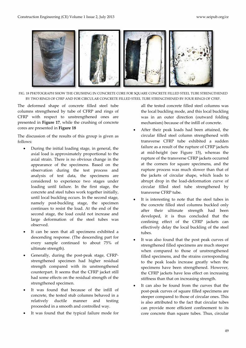
• After their peak loads had been attained, the circular filled steel column strengthened with transverse CFRP tube exhibited a sudden failure as a result of the rupture of CFRP jackets at mid-height (see Figure 15), whereas the rupture of the transverse CFRP jackets occurred at the corners for square specimens, and the rupture process was much slower than that of the jackets of circular shape, which leads to abrupt drop in the load-deformation curve of circular filled steel tube strengthened by transverse CFRP tube.
• It is interesting to note that the steel tubes in the concrete filled steel columns buckled only after their ultimate strength had been developed, it is thus concluded that the confining effect of the CFRP jackets can effectively delay the local buckling of the steel tubes.
• It was also found that the post peak curves of strengthened filled specimens are much steeper when compared to those of unstrengthened filled specimens, and the strains corresponding to the peak loads increase greatly when the specimens have been strengthened. However, the CFRP jackets have less effect on increasing stiffness than that on increasing strength.
• It can also be found from the curves that the post-peak curves of square filled specimens are steeper compared to those of circular ones. This is also attributed to the fact that circular tubes can provide more efficient confinement to its core concrete than square tubes. Thus, circular

www.seipub.org/ce Construction Engineering (CE) Volume 1 Issue 2, July 2013
50
stub columns are more ductile. The reason for different ductilityies in the two cross-sections may be attributed to the shape of local buckling, so that the odds is higher that local buckling is likely to occur in each plate of square tubes than that in circular tubes.
• It seems that the steel tube had less confinement on concrete in strengthened CFST columns compared with its unstrengthened counterpart in the current test. The reason is attributed to the fact that the volume dilation rate is slower under dual confining system than that of concrete confined only by steel tube.
• It was also found that the CFRP composites are more effective in enhancing the load-carrying capacity of the circular filled column than that of square ones. The reason beyond this is ascribe to the fact that the sectional shape has a significant influence on the confining effect of CFRP jackets, since circular steel tubes can provide more efficient confinement to its concrete core than square tubes.
• It can be seen that the four CFRP rings are the most effective configurations among other ring configurations in enhancing the load-carrying capacity of the circular and square filled column for the same total amount of CFRP used. The reason is ascribe to the fact that the rings of CFRP work as the local buckling preventers and the distribution of large number of preventers along the height of column leads to increasing maximum load in comparison to less number of preventers.
• The one intermediate ring preventing buckling in the middle of the CFST column causes buckling transfer to the ends of column. The two rings succeed in preventing top and bottom buckling of CFST and delaying the local buckling of columns, but buckling is transferred to the middle of column. If an intermediate ring beside the top and bottom rings is added, it may be more effective in preventing or delaying buckling in the middle as well as at the ends of CFST column, which can be seen in three and four rings configurations in both circular and square sections.
• The test results indicated that the longitudinal CFRP is more effective than transverse one in square filled column, vice versa in circular ones.
Also, the CFRP rings are more effective in enhancing the load carrying capacity in circular columns than that in square ones. The reason is attributed to the fact that their modes of failure are different, so that the tension in each plate of square filled column occurs in longitudinal direction, while in circular ones, it occurs in radial direction. Hence, when the CFRP fibers are placed in the direction of tension, the CFRP configuration will be more effective. Also, the reason behind this can be attributed to the location of local buckling, so that the roof mechanism occurs at mid height of the column which enables the CFRP tube to delay the local buckling until it is shifted to the ends where the effect of CFRP tube is lesser. Whilst in circular filled columns, the elephant foot occurs at the ends of the column where the effect of CFRP tube is less than that at mid height.
Conclusions
Based on the results obtained from the experimental work of this study, the following conclusions can be drawn: 1) The main conclusion is that the longitudinal CFRP is more effective than transverse CFRP in square hollow or filled column, vice versa in circular ones. 2) It was found that the typical failure mode for all the tested concrete filled steel columns was the local buckling mode which was in an outer direction (outward folding mechanism) because of the infill of concrete. 3) It was confirmed that the ductility of specimens of circular section was much larger than that of the specimens of square section.
4) CFRP composites are more effective in enhancing the load-carrying capacity of circular plain concrete stub columns and circular filled steel stub columns than that in square ones, so that, the increase in circular plain and filled columns are 254.3% and 43.4% respectively while the increase in square plain and filled columns are 101% and 25.66% respectively.
5) CFRP composites are more effective in enhancing the load-carrying capacity of plain concrete stub columns than that of hollow or filled steel stub columns, so that, the increase in plain ones is 254.3%, while in hollow and filled ones it is 31.1% and 43.4% respectively. 6) It was found that the ductility of hollow and filled

Construction Engineering (CE) Volume 1 Issue 2, July 2013 www.seipub.org/ce
51
specimens of circular section was much larger than that of the specimens of square section. 7) All hollow and filled specimens exhibited a descending response. Generally, during the post-peak stage, strengthened specimens had higher residual strength compared with their unstrengthened counterpart. It seems that the CFRP jacket still had some effects on the residual strength of the strengthened specimen. 8) After their peak loads had been attained, the circular specimens exhibited a sudden failure as a result of the rupture of CFRP jackets at mid-height, whereas the rupture of the CFRP jackets occurred at the corners for square specimens, and the rupture process was much slower than that of the jackets of circular shape. 9) It can also be found from the curves that the post-peak curves of square filled specimens are steeper compared to those of circular ones. Thus, circular filled stub columns are more ductile. 10) For the same total amount of CFRP, it can be seen that the more CFRP rings are, the more effective configuration among other ring's configurations in enhancing the load-carrying capacity of the circular and square filled column.
REFERENCES
ASTM A 370-05(2005)," Standard Test Method and Definition
for Mechanical Testing of Steel Products", 2005 Annual
Book ofASTM Standards, Vol.01.01, ASTM, Philadelphia,
PA.
Choi., K-K,and Xiao., Y, (2010), “Analytical Model of
Circular CFRP Confined Concrete-Filled Steel Tubular
Columns under Axial Compression”, Journal of
Composites for Construction © ASCE, Vol. 14, No. 1, pp.
125-133.
Dabaon, M.A., El-Boghdadi, M.H, and Hassanein, M.F.,
(2008)”Experimental investigation on concrete-filled
stainless steel stiffened tubular stub columns”. Journal of
engineering structures, Cited by Ref.[22].
Elchalakani, M., Zhao, X.-L. , and Grzebieta, R., (2002), "Tests
on concrete filled double-skin (CHS outer and SHS inner)
composite short columns under axial compression",
Journal of Thin-Walled Structures, 40, pp. 415–441.
EFNARC, (2005): European Federation Dedicated to
Specialist Construction Chemicals and Concrete systems
“The European Guidelines for Self-Compacting Concrete
Specification, Production and Use”, 1st edition.
Gupta, P.K. Sarda, S.M. and Kumar, M.S. (2007),
“Experimental and Computational Study of Concrete
Filled Steel Tubular Columns Under Axial Loads”, Civil
Engineering Group, Birla Institute of Technology and
Science Pilani, Rajasthan333031, India, Journal of
Constructional Steel Research,63, pp 182-193.
Han, L.-H., and Yao, G.-H., (2004), “Experimental behavior
of thin-walled hollow structural steel (HSS) columns
filled with self-consolidating concrete (SCC)”, Thin-
Walled Structures 42,pp. 1357–1377.
Mechanical Testing of Steel Products" , 2005 Annual Book
ofASTM Standards, Vol.01.01, ASTM, Philadelphia, PA.
Sika , (2009), " SikaWarp®- 230C Woven carbon fiber fabric
for structural strengthening", Technical Data Sheet.
Sika, (2008), "Sikadur®-330 Two parts Epoxy Impregnation
Resin", Technical Data Sheet.
Tao, Z., Han, L.-H., and Wang, L.-L., (2007), "Compressive
and flexural behavior of CFRP-repaired concrete-filled
steel tubes after exposure to fire", Journal of
Constructional Steel Research, 63, pp. 1116–1126.
Teng, J.G. and Hu, Y.M., (2007), "Behavior of FRP-jacketed
circular steel tubes and cylindrical shells under axial
compression", Journal of Construction and Building
Materials, 21, pp. 827–838.
Xiong, D.-X., Zha, X.-X. (2007), “A numerical investigation
on the behavior of concrete-filled steel tubular columns
under initial stresses”,Journal of Constructional Steel
Research 63,pp. 599-611.
Zhao, X.L., Wilkinson, T., and Hancock, G., (2005), “Cold-
Formed Tubular Members and Connections”, ch.4 ,pp.
67-89.