Embed Size (px)
Citation preview

Electronic System Design Finite State Machine
Nurul Hazlina 1
Finite State Machine
1. Review on counter design
2. State Diagrams for FSM
3. Moore & Mealy Models
4. State Minimization
5. Examples
6. HDL for FSM

Electronic System Design Finite State Machine
Nurul Hazlina 2
Sequential Logic Implementation
• Models for representing sequential circuits
– Finite-state machines (Moore and Mealy)
– Representation of memory (states)
– Changes in state (transitions)
• Design procedure
– State diagrams
– State transition table
– Next state functions

Electronic System Design Finite State Machine
Nurul Hazlina 3
2 – STATE DIAGRAM FOR FSM
Electronic System Design Finite State Machine
Nurul Hazlina 4
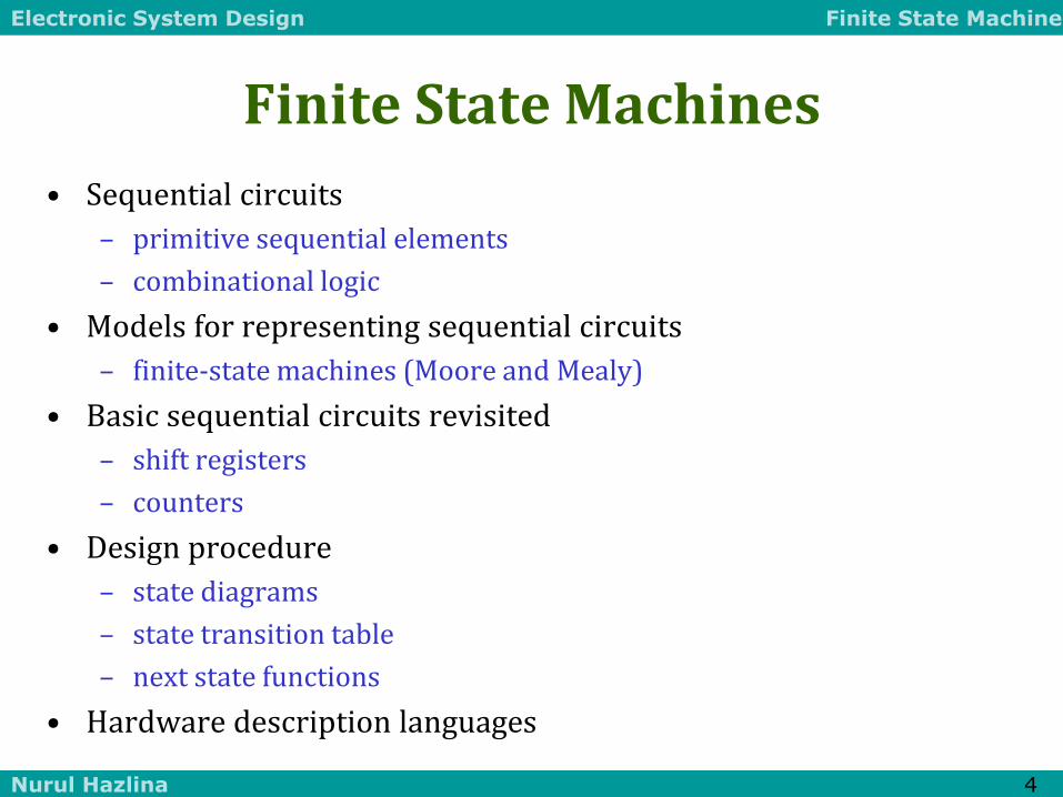
Finite State Machines
• Sequential circuits
– primitive sequential elements
– combinational logic
• Models for representing sequential circuits
– finite-state machines (Moore and Mealy)
• Basic sequential circuits revisited
– shift registers
– counters
• Design procedure
– state diagrams
– state transition table
– next state functions
• Hardware description languages
Electronic System Design Finite State Machine
Nurul Hazlina 5
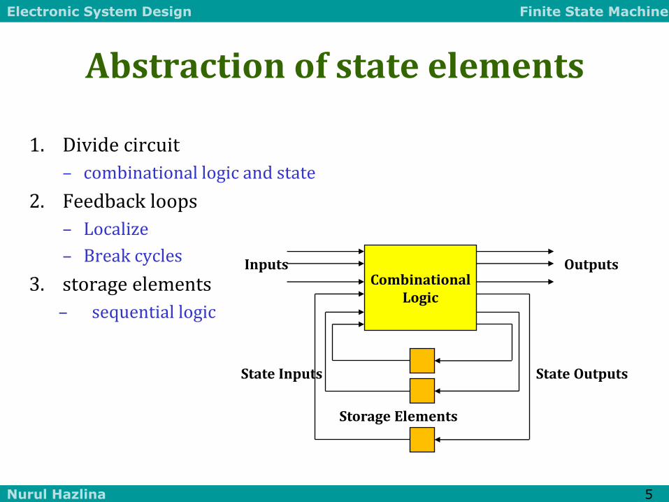
Abstraction of state elements
1. Divide circuit
– combinational logic and state
2. Feedback loops
– Localize
– Break cycles
3. storage elements
– sequential logic
Combinational Logic
Storage Elements
Outputs
State Outputs State Inputs
Inputs

Electronic System Design Finite State Machine
Nurul Hazlina 6
Forms of sequential logic
1. Asynchronous sequential logic
– state changes occur whenever state inputs change
– elements may be simple wires or delay elements
2. Synchronous sequential logic
– state changes occur in lock step across all storage elements
– using a periodic waveform - the clock
Clock

Electronic System Design Finite State Machine
Nurul Hazlina 7
In = 0
In = 1
In = 0 In = 1
100
010
110
111 001
FSM Representations
1. States
– determined by possible values in sequential storage elements
2. Transitions
– change of state
3. Clock
– controls when state can change by controlling storage elements
4. Sequential logic
– sequences through a series of states
– based on sequence of values on input signals
– clock period defines elements of sequence

Electronic System Design Finite State Machine
Nurul Hazlina 8
Can any sequential system be represented with a state diagram?
• Shift register
– input value shown on transition arcs
– output values shown within state node
100 110
111
011
101 010 000
001
1
1
1
1
0
0
0 0
1
1
1
0
0
1
0 0
D Q D Q D Q IN
OUT1 OUT2 OUT3
CLK

Electronic System Design Finite State Machine
Nurul Hazlina 9
1- DESIGN A COUNTER

Electronic System Design Finite State Machine
Nurul Hazlina 10
010
100
110
011 001
000
101 111
3-bit up-counter
Counters are simple finite state machines
• Counters
– proceed through well-defined sequence of states in response to enable
• Many types of counters: binary, BCD, Gray-code
– 3-bit up-counter: 000, 001, 010, 011, 100, 101, 110, 111, 000, ...
– 3-bit down-counter: 111, 110, 101, 100, 011, 010, 001, 000, 111, ...
Electronic System Design Finite State Machine
Nurul Hazlina 11
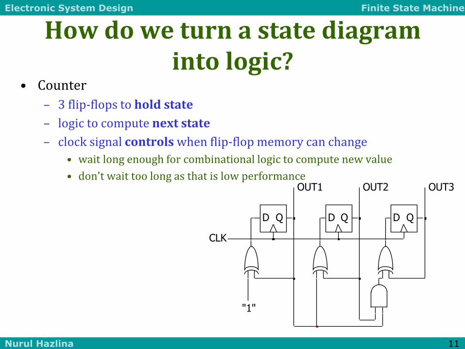
How do we turn a state diagram into logic?
• Counter
– 3 flip-flops to hold state
– logic to compute next state
– clock signal controls when flip-flop memory can change
• wait long enough for combinational logic to compute new value
• don't wait too long as that is low performance
D Q D Q D Q
OUT1 OUT2 OUT3
CLK
"1"

Electronic System Design Finite State Machine
Nurul Hazlina 12
FSM design procedure
• Start with counters
– simple because output is just state
– simple because no choice of next state based on input
• State diagram to state transition table
– tabular form of state diagram
– like a truth-table
• State encoding
– decide on representation of states
– for counters it is simple: just its value
• Implementation
– flip-flop for each state bit
– combinational logic based on encoding
Electronic System Design Finite State Machine
Nurul Hazlina 13
010
100
110
011 001
000
101 111
3-bit up-counter
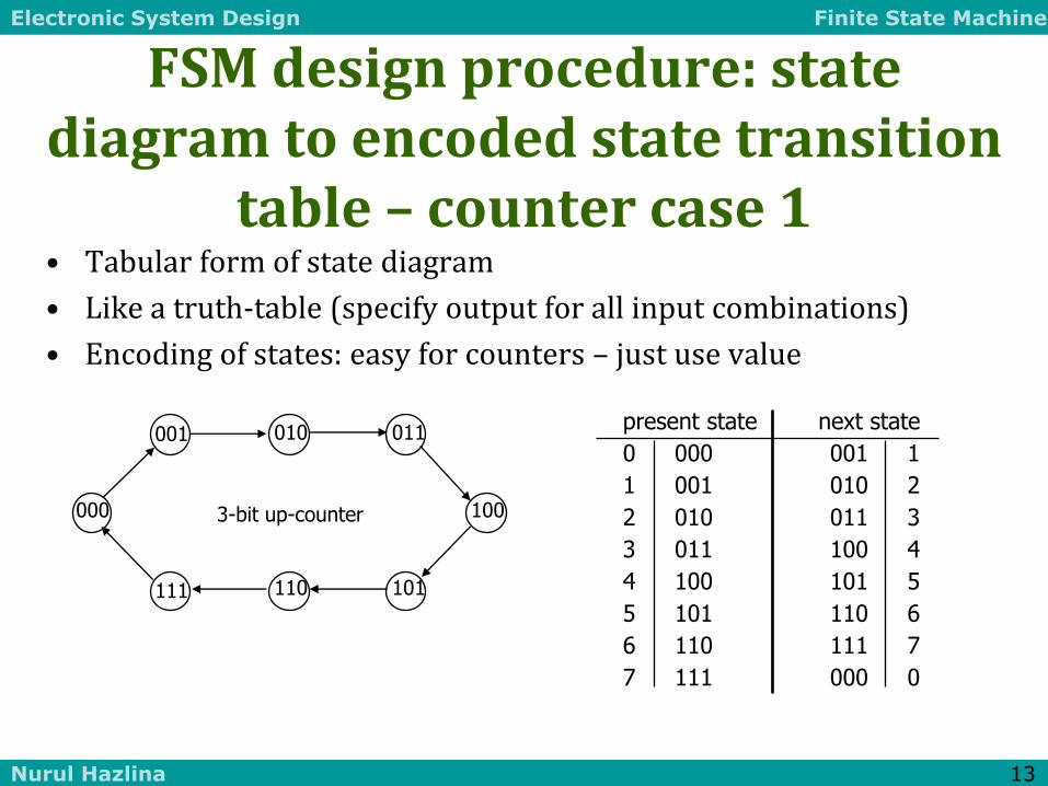
present state next state
0 000 001 1
1 001 010 2
2 010 011 3
3 011 100 4
4 100 101 5
5 101 110 6
6 110 111 7
7 111 000 0
FSM design procedure: state diagram to encoded state transition
table – counter case 1 • Tabular form of state diagram
• Like a truth-table (specify output for all input combinations)
• Encoding of states: easy for counters – just use value

Electronic System Design Finite State Machine
Nurul Hazlina 14
C3 C2 C1 N3 N2 N1
0 0 0 0 0 1
0 0 1 0 1 0
0 1 0 0 1 1
0 1 1 1 0 0
1 0 0 1 0 1
1 0 1 1 1 0
1 1 0 1 1 1
1 1 1 0 0 0
N1 <= C1’ N2 <= C1C2’ + C1’C2 <= C1 xor C2 N3 <= C1C2C3’ + C1’C3 + C2’C3 <= (C1C2)C3’ + (C1’ + C2’)C3 <= (C1C2)C3’ + (C1C2)’C3 <= (C1C2) xor C3
Verilog notation to show function represents an input to D-FF
Implementation
• D flip-flop for each state bit
• Combinational logic based on encoding
0 0
0 1
1 1
0 1 C1
C2
C3 N3
1 1
0 0
1 1
0 0 C1
C2
C3 N1
0 1
1 0
1 0
0 1 C1
C2
C3 N2

Electronic System Design Finite State Machine
Nurul Hazlina 15
In C1 C2 C3 N1 N2 N3 0 0 0 0 0 0 0 0 0 0 1 0 0 0 0 0 1 0 0 0 1 0 0 1 1 0 0 1 0 1 0 0 0 1 0 0 1 0 1 0 1 0 0 1 1 0 0 1 1 0 1 1 1 0 1 1 1 0 0 0 1 0 0 1 0 0 1 1 0 0 1 0 1 0 1 0 1 1 0 1 1 1 0 1 1 1 0 0 1 1 0 1 1 0 1 1 1 0 1 1 1 0 1 1 1 1 1 1 1 1 1 1
N1 <= In N2 <= C1 N3 <= C2
Back to the shift register - counter case 2
• Input determines next state
100 110
111
011
101 010 000
001
0
1
1 1
1 1
1
1
0
0
0
0 0
1
0 0
D Q D Q D Q IN
OUT1 OUT2 OUT3
CLK

Electronic System Design Finite State Machine
Nurul Hazlina 16
More complex counter example - counter case 3
• Complex counter
– repeats 5 states in sequence
– not a binary number representation
• Step 1: derive the state transition diagram
– count sequence: 000, 010, 011, 101, 110
• Step 2: derive the state transition table from the state transition diagram
Present State Next State C B A C+ B+ A+ 0 0 0 0 1 0 0 0 1 – – – 0 1 0 0 1 1 0 1 1 1 0 1 1 0 0 – – – 1 0 1 1 1 0 1 1 0 0 0 0 1 1 1 – – –
note the don't care conditions that arise from the unused state codes
010
000 110
101
011

Electronic System Design Finite State Machine
Nurul Hazlina 17
C+ <= A
B+ <= B’ + A’C’
A+ <= BC’
More complex counter example (cont’d)
• Step 3: K-maps for next state functions
0 0
X 1
0 X
X 1 A
B
C C+
1 1
X 0
0 X
X 1 A
B
C B+
0 1
X 1
0 X
X 0 A
B
C A+

Electronic System Design Finite State Machine
Nurul Hazlina 18
Self-starting counters (cont’d) – counter case 3a
• Re-deriving state transition table from don't care assignment
0 0
1 1
0 0
1 1 A
B
C C+
1 1
1 0
0 1
0 1 A
B
C B+
0 1
0 1
0 0
0 0 A
B
C A+
Present State Next State C B A C+ B+ A+ 0 0 0 0 1 0 0 0 1 1 1 0 0 1 0 0 1 1 0 1 1 1 0 1 1 0 0 0 1 0 1 0 1 1 1 0 1 1 0 0 0 0 1 1 1 1 0 0
010
000 110
101
011
001 111
100

Electronic System Design Finite State Machine
Nurul Hazlina 19
Self-starting counters
• Start-up states
– at power-up, counter may be in an unused or invalid state
– designer must guarantee that it (eventually) enters a valid state
• Self-starting solution
– design counter so that invalid states eventually transition to a valid state
– may limit exploitation of don't cares implementation on previous slide
010
000 110
101
011
001 111
100
010
000 110
101
011
001 111
100
Electronic System Design Finite State Machine
Nurul Hazlina 20
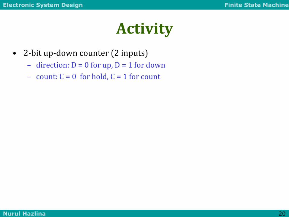
Activity
• 2-bit up-down counter (2 inputs)
– direction: D = 0 for up, D = 1 for down
– count: C = 0 for hold, C = 1 for count
01
00 11
10
C=0 D=X
C=0 D=X
C=0 D=X
C=0 D=X
C=1 D=0
C=1 D=0
C=1 D=0
C=1 D=0
C=1 D=1
S1 S0 C D N1 N0 0 0 0 0 0 0 0 0 0 1 0 0 0 0 1 0 0 1 0 0 1 1 1 1 0 1 0 0 0 1 0 1 0 1 0 1 0 1 1 0 1 0 0 1 1 1 0 0 1 0 0 0 1 0 1 0 0 1 1 0 1 0 1 0 1 1 1 0 1 1 0 1 1 1 0 0 1 1 1 1 0 1 1 1 1 1 1 0 0 0 1 1 1 1 1 0

Electronic System Design Finite State Machine
Nurul Hazlina 21
Activity (cont’d)
S1 S0 C D N1 N0 0 0 0 0 0 0 0 0 0 1 0 0 0 0 1 0 0 1 0 0 1 1 1 1 0 1 0 0 0 1 0 1 0 1 0 1 0 1 1 0 1 0 0 1 1 1 0 0 1 0 0 0 1 0 1 0 0 1 1 0 1 0 1 0 1 1 1 0 1 1 0 1 1 1 0 0 1 1 1 1 0 1 1 1 1 1 1 0 0 0 1 1 1 1 1 0
N1 = C’S1 + CDS0’S1’ + CDS0S1 + CD’S0S1’ + CD’S0’S1 = C’S1 + C(D’(S1 S0) + D(S1 S0))
N0 = CS0’ + C’S0 0 1 1 0
0 1 1 0
1 0 0 1
1 0 0 1
D
S1
S0
C
0 0 1 1
0 0 1 1
1 0 1 0
0 1 0 1
D
S1
S0
C
Electronic System Design Finite State Machine
Nurul Hazlina 22
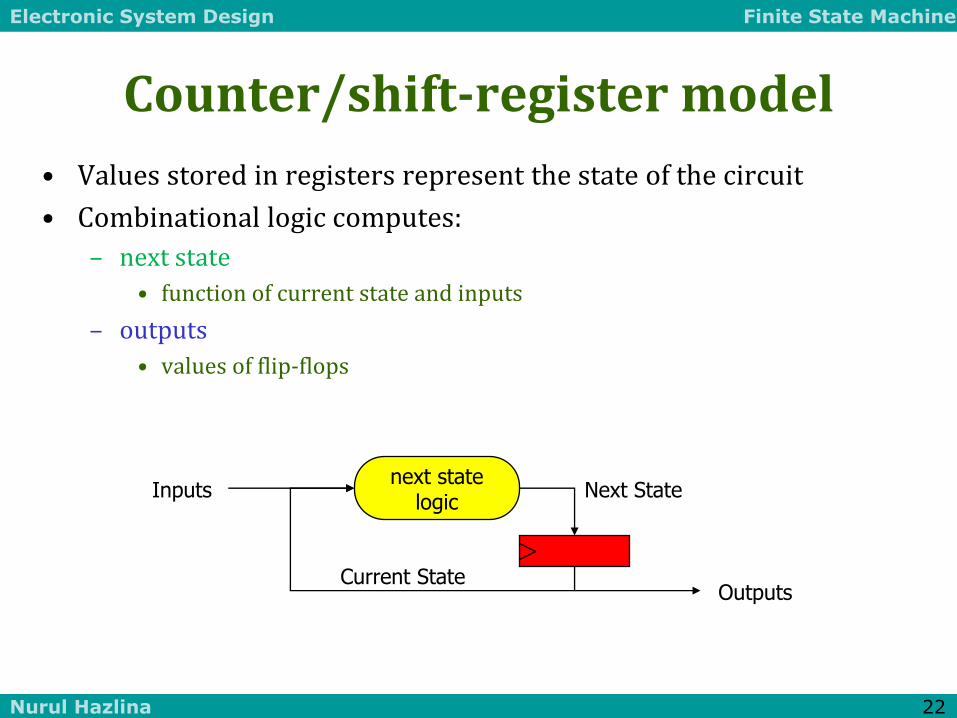
Counter/shift-register model
• Values stored in registers represent the state of the circuit
• Combinational logic computes:
– next state
• function of current state and inputs
– outputs
• values of flip-flops
Inputs
Outputs
Next State
Current State
next state logic

Electronic System Design Finite State Machine
Nurul Hazlina 23
General state machine model
• Values stored in registers represent the state of the circuit
• Combinational logic computes:
– next state
• function of current state and inputs
– outputs
• function of current state and inputs (Mealy machine)
• function of current state only (Moore machine)
Inputs
Outputs
Next State
Current State
output logic
next state logic

Electronic System Design Finite State Machine
Nurul Hazlina 24
State machine model (cont’d)
• States: S1, S2, ..., Sk
• Inputs: I1, I2, ..., Im
• Outputs: O1, O2, ..., On
• Transition function: Fs(Si, Ij)
• Output function: Fo(Si) or Fo(Si, Ij)
Inputs
Outputs
Next State
Current State
output logic
next state logic
Clock
Next State
State
0 1 2 3 4 5
Electronic System Design Finite State Machine
Nurul Hazlina 25
3 - MOORE & MEALY MACHINES

Electronic System Design Finite State Machine
Nurul Hazlina 26
Mealy vs Moore Machines
• Mealy machines tend to have less states
– different outputs on arcs (n2) rather than states (n)
• Moore machines are safer to use
– outputs change at clock edge (always one cycle later)
– in Mealy machines, input change can cause output change as soon as logic is done – a big problem when two machines are interconnected – asynchronous feedback may occur if one isn’t careful
• Mealy machines react faster to inputs
– react in same cycle – don't need to wait for clock
– in Moore machines, more logic may be necessary to decode state into outputs – more gate delays after clock edge

Electronic System Design Finite State Machine
Nurul Hazlina 27
Comparison of Mealy and Moore machines (cont’d)
• Moore
• Mealy
• Synchronous Mealy
state feedback
inputs
outputs reg
combinational
logic for
next state logic for
outputs
inputs outputs
state feedback
reg combinational
logic for
next state
logic for
outputs
inputs outputs
state feedback
reg combinational
logic for
next state
logic for
outputs

Electronic System Design Finite State Machine
Nurul Hazlina 28
D/1
E/1
B/0
A/0
C/0
1
0
0
0
0
1
1
1
1
0
reset
current next
reset input state state output
1 – – A
0 0 A B 0
0 1 A C 0
0 0 B B 0
0 1 B D 0
0 0 C E 0
0 1 C C 0
0 0 D E 1
0 1 D C 1
0 0 E B 1
0 1 E D 1
Outputs for a Moore machine
• Output is only function of state
– specify in state bubble in state diagram
– example: sequence detector for 01 or 10
Electronic System Design Finite State Machine
Nurul Hazlina 29
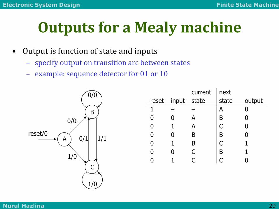
current next
reset input state state output
1 – – A 0
0 0 A B 0
0 1 A C 0
0 0 B B 0
0 1 B C 1
0 0 C B 1
0 1 C C 0
B
A
C
0/1
0/0
0/0
1/1
1/0
1/0
reset/0
Outputs for a Mealy machine
• Output is function of state and inputs
– specify output on transition arc between states
– example: sequence detector for 01 or 10

Electronic System Design Finite State Machine
Nurul Hazlina 30
Registered Mealy machine (really Moore)
• Synchronous (or registered) Mealy machine
– registered state AND outputs
– avoids ‘glitchy’ outputs
– easy to implement in PLDs
• Moore machine with no output decoding
– outputs computed on transition to next state rather than after entering
– view outputs as expanded state vector
Inputs
Outputs
Current State
output logic
next state logic

Electronic System Design Finite State Machine
Nurul Hazlina 31
Activity
A 3-bit sequence detector will detect 111 and 001. All the input and output will be reset after each sequence had been detected. An example of input/output sequence that satisfies the conditions of the network specifications is as follows;
x = 0 1 1 1 1 1 0 1 0 1 0 0 0 0 1 0 1 1
z = 0 0 0 0 0 1 0 0 0 0 0 0 0 0 1 0 0 0
Draw the state transition diagram of the system using Mealy machine method.
Electronic System Design Finite State Machine
Nurul Hazlina 32
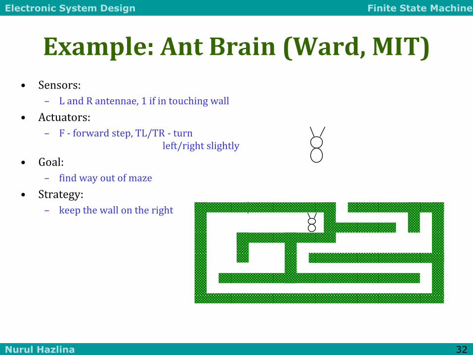
Example: Ant Brain (Ward, MIT)
• Sensors:
– L and R antennae, 1 if in touching wall
• Actuators:
– F - forward step, TL/TR - turn left/right slightly
• Goal:
– find way out of maze
• Strategy:
– keep the wall on the right
Electronic System Design Finite State Machine
Nurul Hazlina 33
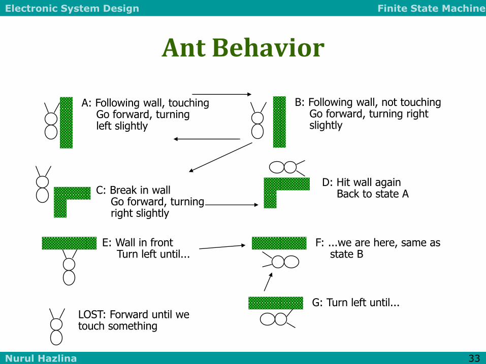
Ant Behavior
A: Following wall, touching Go forward, turning left slightly
B: Following wall, not touching Go forward, turning right slightly
C: Break in wall Go forward, turning right slightly
D: Hit wall again Back to state A
E: Wall in front Turn left until...
F: ...we are here, same as state B
G: Turn left until... LOST: Forward until we touch something

Electronic System Design Finite State Machine
Nurul Hazlina 34
Designing an Ant Brain
• State Diagram
R’ C
(TR, F) R’
L’ R’
B (TR, F)
L’ R’
L
R
A (TL, F)
R
L’ R L + R
E/G (TL)
L + R LOST (F)
L’ R’

Electronic System Design Finite State Machine
Nurul Hazlina 35
Synthesizing the Ant Brain Circuit
• Encode States Using a Set of State Variables
– Arbitrary choice - may affect cost, speed
• Use Transition Truth Table
– Define next state function for each state variable
– Define output function for each output
• Implement next state and output functions using combinational logic
– 2-level logic (ROM/PLA/PAL)
– Multi-level logic
– Next state and output functions can be optimized together
Electronic System Design Finite State Machine
Nurul Hazlina 36
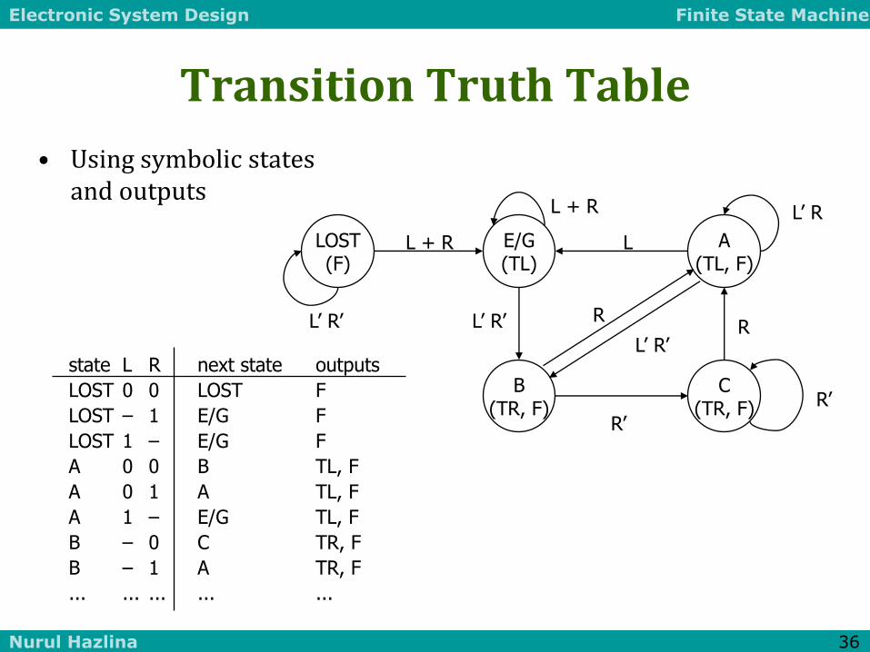
Transition Truth Table
• Using symbolic states and outputs
LOST (F)
E/G (TL)
A (TL, F)
B (TR, F)
C (TR, F) R’
R’
L’ R’
R L’ R’
L
R
L’ R L + R
L + R
L’ R’
state L R next state outputs
LOST 0 0 LOST F
LOST – 1 E/G F
LOST 1 – E/G F
A 0 0 B TL, F
A 0 1 A TL, F
A 1 – E/G TL, F
B – 0 C TR, F
B – 1 A TR, F
... ... ... ... ...

Electronic System Design Finite State Machine
Nurul Hazlina 37
Synthesis
• 5 states : at least 3 state variables required (X, Y, Z)
– State assignment (in this case, arbitrarily chosen)
state L R next state outputs
X,Y,Z X', Y', Z' F TR TL
0 0 0 0 0 0 0 0 1 0 0
0 0 0 0 1 0 0 1 1 0 0
... ... ... ... ...
0 1 0 0 0 0 1 1 1 0 1
0 1 0 0 1 0 1 0 1 0 1
0 1 0 1 0 0 0 1 1 0 1
0 1 0 1 1 0 0 1 1 0 1
0 1 1 0 0 1 0 0 1 1 0
0 1 1 0 1 0 1 0 1 1 0
... ... ... ... ...
LOST - 000
E/G - 001
A - 010
B - 011
C - 100 it now remains to synthesize these 6 functions
Electronic System Design Finite State Machine
Nurul Hazlina 38
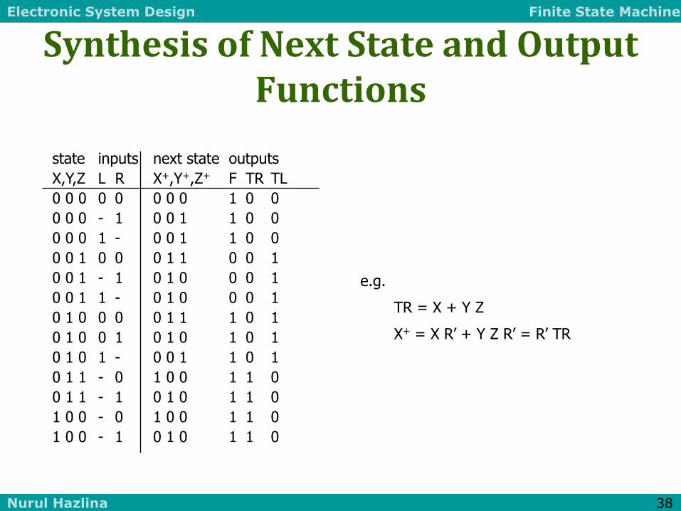
Synthesis of Next State and Output Functions
state inputs next state outputs
X,Y,Z L R X+,Y+,Z+ F TR TL
0 0 0 0 0 0 0 0 1 0 0
0 0 0 - 1 0 0 1 1 0 0
0 0 0 1 - 0 0 1 1 0 0
0 0 1 0 0 0 1 1 0 0 1
0 0 1 - 1 0 1 0 0 0 1
0 0 1 1 - 0 1 0 0 0 1
0 1 0 0 0 0 1 1 1 0 1
0 1 0 0 1 0 1 0 1 0 1
0 1 0 1 - 0 0 1 1 0 1
0 1 1 - 0 1 0 0 1 1 0
0 1 1 - 1 0 1 0 1 1 0
1 0 0 - 0 1 0 0 1 1 0
1 0 0 - 1 0 1 0 1 1 0
e.g.
TR = X + Y Z
X+ = X R’ + Y Z R’ = R’ TR

Electronic System Design Finite State Machine
Nurul Hazlina 39
Circuit Implementation
• Outputs are a function of the current state only - Moore machine
L R
F TR TL
Next State
Current State
output logic
next state logic
X+ Y+ Z+
X Y Z

Electronic System Design Finite State Machine
Nurul Hazlina 40
Don’t Cares in FSM Synthesis
• What happens to the "unused" states (101, 110, 111)?
• Exploited as don't cares to minimize the logic
– If states can't happen, then don't care what the functions do
– if states do happen, we may be in trouble
Ant is in deep trouble
if it gets in this state
000 (F)
001 (TL)
010 (TL, F)
011 (TR, F)
100 (TR, F) R’
R’
L’ R’
R L’ R’
L
R
L’ R L + R
L + R
L’ R’
111
101
110

Electronic System Design Finite State Machine
Nurul Hazlina 41
State Minimization
• Fewer states may mean fewer state variables
• High-level synthesis may generate many redundant states
• Two state are equivalent if they are impossible to distinguish from the outputs of the FSM, i. e., for any input sequence the outputs are the same
• Two conditions for two states to be equivalent:
– 1) Output must be the same in both states
– 2) Must transition to equivalent states for all input combinations

Electronic System Design Finite State Machine
Nurul Hazlina 42
Ant Brain Revisited
• Any equivalent states?
LOST (F)
E/G (TL)
A (TL, F)
B (TR, F)
C (TR, F)
R’
R’
L’ R’
R L’ R’
L
R
L’ R L + R
L + R
L’ R’

Electronic System Design Finite State Machine
Nurul Hazlina 43
New Improved Brain
• Merge equivalent B and C states
• Behavior is exactly the same as the 5-state brain
• We now need only 2 state variables rather than 3
LOST (F)
E/G (TL)
A (TL, F)
B/C (TR, F)
R’
L’ R’
R L’ R’
L
L’ R L + R
L + R
L’ R’
Electronic System Design Finite State Machine
Nurul Hazlina 44
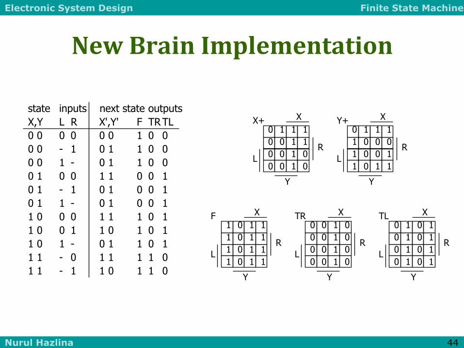
New Brain Implementation
state inputs next state outputs
X,Y L R X',Y' F TR TL
0 0 0 0 0 0 1 0 0
0 0 - 1 0 1 1 0 0
0 0 1 - 0 1 1 0 0
0 1 0 0 1 1 0 0 1
0 1 - 1 0 1 0 0 1
0 1 1 - 0 1 0 0 1
1 0 0 0 1 1 1 0 1
1 0 0 1 1 0 1 0 1
1 0 1 - 0 1 1 0 1
1 1 - 0 1 1 1 1 0
1 1 - 1 1 0 1 1 0
1 0 1 1
1 0 1 1
1 0 1 1
1 0 1 1
X F
Y
R
L
0 0 1 0
0 0 1 0
0 0 1 0
0 0 1 0
X TR
Y
R
L
0 1 0 1
0 1 0 1
0 1 0 1
0 1 0 1
X TL
Y
R
L
0 1 1 1
0 0 1 1
0 0 1 0
0 0 1 0
X X+
Y
R
L
0 1 1 1
1 0 0 0
1 0 0 1
1 0 1 1
X Y+
Y
R
L

Electronic System Design Finite State Machine
Nurul Hazlina 45
Example: Vending Machine
• Release item after 15 cents are deposited
• Single coin slot for dimes, nickels
• No change
Vending Machine
FSM
N
D
Reset
Clock
Open Coin Sensor
Release Mechanism

Electronic System Design Finite State Machine
Nurul Hazlina 46
Example: Vending Machine (cont’d)
• Suitable Abstract Representation
– Tabulate typical input sequences:
• 3 nickels
• nickel, dime
• dime, nickel
• two dimes
– Draw state diagram:
• Inputs: N, D, reset
• Output: open chute
– Assumptions:
• Assume N and D asserted for one cycle
• Each state has a self loop for N = D = 0 (no coin)
S0
Reset
S2
D
S6 [open]
D
S4 [open]
D
S1
N
S3
N
S7 [open]
N
S5 [open]
N

Electronic System Design Finite State Machine
Nurul Hazlina 47
Example: Vending Machine (cont’d)
• Minimize number of states - reuse states whenever possible
symbolic state table
present inputs next output state D N state open 0¢ 0 0 0¢ 0 0 1 5¢ 0 1 0 10¢ 0 1 1 – – 5¢ 0 0 5¢ 0 0 1 10¢ 0 1 0 15¢ 0 1 1 – – 10¢ 0 0 10¢ 0 0 1 15¢ 0 1 0 15¢ 0 1 1 – – 15¢ – – 15¢ 1
0¢
Reset
5¢
N
N
N + D
10¢
D
15¢ [open]
D
Electronic System Design Finite State Machine
Nurul Hazlina 48
Example: Vending Machine (cont’d)
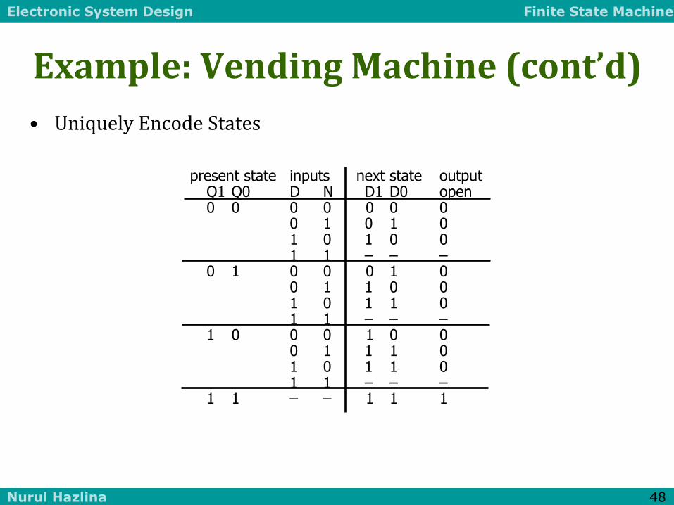
• Uniquely Encode States
present state inputs next state output Q1 Q0 D N D1 D0 open 0 0 0 0 0 0 0 0 1 0 1 0 1 0 1 0 0 1 1 – – – 0 1 0 0 0 1 0 0 1 1 0 0 1 0 1 1 0 1 1 – – – 1 0 0 0 1 0 0 0 1 1 1 0 1 0 1 1 0 1 1 – – – 1 1 – – 1 1 1

Electronic System Design Finite State Machine
Nurul Hazlina 49
Example: Vending Machine (cont’d)
• Mapping to Logic
D1 = Q1 + D + Q0 N
D0 = Q0’ N + Q0 N’ + Q1 N + Q1 D
OPEN = Q1 Q0
0 0 1 1
0 1 1 1
X X X X
1 1 1 1
Q1 D1
Q0
N
D
0 1 1 0
1 0 1 1
X X X X
0 1 1 1
Q1 D0
Q0
N
D
0 0 1 0
0 0 1 0
X X X X
0 0 1 0
Q1 Open
Q0
N
D
Electronic System Design Finite State Machine
Nurul Hazlina 50
Example: Vending Machine (cont’d)
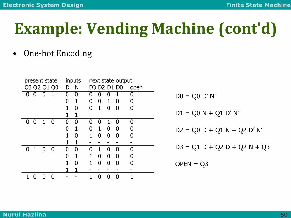
• One-hot Encoding
present state inputs next state output Q3 Q2 Q1 Q0 D N D3 D2 D1 D0 open
0 0 0 1 0 0 0 0 0 1 0 0 1 0 0 1 0 0 1 0 0 1 0 0 0 1 1 - - - - - 0 0 1 0 0 0 0 0 1 0 0 0 1 0 1 0 0 0
1 0 1 0 0 0 0 1 1 - - - - - 0 1 0 0 0 0 0 1 0 0 0 0 1 1 0 0 0 0 1 0 1 0 0 0 0 1 1 - - - - -
1 0 0 0 - - 1 0 0 0 1
D0 = Q0 D’ N’
D1 = Q0 N + Q1 D’ N’
D2 = Q0 D + Q1 N + Q2 D’ N’
D3 = Q1 D + Q2 D + Q2 N + Q3
OPEN = Q3

Electronic System Design Finite State Machine
Nurul Hazlina 51
Equivalent Mealy and Moore State Diagrams
• Moore machine
– outputs associated with state
0¢ [0]
10¢ [0]
5¢ [0]
15¢ [1]
N’ D’ + Reset
D
D
N
N+D
N
N’ D’
Reset’
N’ D’
N’ D’
Reset
Mealy machine outputs associated with transitions
0¢
10¢
5¢
15¢
(N’ D’ + Reset)/0
D/0
D/1
N/0
N+D/1
N/0
N’ D’/0
Reset’/1
N’ D’/0
N’ D’/0
Reset/0

Electronic System Design Finite State Machine
Nurul Hazlina 52
Example: Traffic Light Controller
• A busy highway is intersected by a little used farmroad
• Detectors C sense the presence of cars waiting on the farmroad
– with no car on farmroad, light remain green in highway direction
– if vehicle on farmroad, highway lights go from Green to Yellow to Red, allowing the farmroad lights to become green
– these stay green only as long as a farmroad car is detected but never longer than a set interval
– when these are met, farm lights transition from Green to Yellow to Red, allowing highway to return to green
– even if farmroad vehicles are waiting, highway gets at least a set interval as green
Electronic System Design Finite State Machine
Nurul Hazlina 53
Example: Traffic Light Controller
• Assume you have an interval timer that generates:
– a short time pulse (TS) and
– a long time pulse (TL),
– in response to a set (ST) signal.
– TS is to be used for timing yellow lights and TL for green lights

Electronic System Design Finite State Machine
Nurul Hazlina 54
Example: Traffic Light Controller (cont’)
• Highway/farm road intersection
highway
farm road
car sensors

Electronic System Design Finite State Machine
Nurul Hazlina 55
Example: Traffic Light Controller (cont’)
• Tabulation of Inputs and Outputs inputs description outputs description reset place FSM in initial state HG, HY, HR assert green/yellow/red highway lights C detect vehicle on the farm road FG, FY, FR assert green/yellow/red highway lights TS short time interval expired ST start timing a short or long interval TL long time interval expired
• Tabulation of unique states – some light configurations imply others state description S0 highway green (farm road red) S1 highway yellow (farm road red) S2 farm road green (highway red) S3 farm road yellow (highway red)
Electronic System Design Finite State Machine
Nurul Hazlina 56
Example: Traffic Light Controller (cont’)
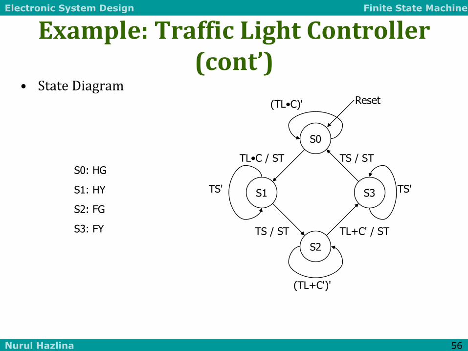
• State Diagram
S0: HG
S1: HY
S2: FG
S3: FY
Reset
TS'
TS / ST
(TL•C)'
TL•C / ST
TS'
TS / ST
(TL+C')'
TL+C' / ST
S0
S2
S3 S1
Electronic System Design Finite State Machine
Nurul Hazlina 57
Example: Traffic Light Controller (cont’)
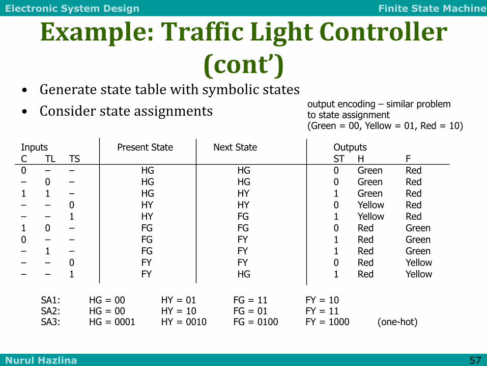
• Generate state table with symbolic states
• Consider state assignments
Inputs Present State Next State Outputs C TL TS ST H F
0 – – HG HG 0 Green Red – 0 – HG HG 0 Green Red 1 1 – HG HY 1 Green Red – – 0 HY HY 0 Yellow Red – – 1 HY FG 1 Yellow Red 1 0 – FG FG 0 Red Green
0 – – FG FY 1 Red Green – 1 – FG FY 1 Red Green – – 0 FY FY 0 Red Yellow – – 1 FY HG 1 Red Yellow
SA1: HG = 00 HY = 01 FG = 11 FY = 10 SA2: HG = 00 HY = 10 FG = 01 FY = 11 SA3: HG = 0001 HY = 0010 FG = 0100 FY = 1000 (one-hot)
output encoding – similar problem to state assignment (Green = 00, Yellow = 01, Red = 10)

Electronic System Design Finite State Machine
Nurul Hazlina 58
Logic for Different State Assignments
• SA1 NS1 = C•TL'•PS1•PS0 + TS•PS1'•PS0 + TS•PS1•PS0' + C'•PS1•PS0 + TL•PS1•PS0 NS0 = C•TL•PS1'•PS0' + C•TL'•PS1•PS0 + PS1'•PS0 ST = C•TL•PS1'•PS0' + TS•PS1'•PS0 + TS•PS1•PS0' + C'•PS1•PS0 + TL•PS1•PS0 H1 = PS1 H0 = PS1'•PS0 F1 = PS1' F0 = PS1•PS0'
• SA2 NS1 = C•TL•PS1' + TS'•PS1 + C'•PS1'•PS0 NS0 = TS•PS1•PS0' + PS1'•PS0 + TS'•PS1•PS0 ST = C•TL•PS1' + C'•PS1'•PS0 + TS•PS1 H1 = PS0 H0 = PS1•PS0' F1 = PS0' F0 = PS1•PS0
• SA3 NS3 = C'•PS2 + TL•PS2 + TS'•PS3 NS2 = TS•PS1 + C•TL'•PS2 NS1 = C•TL•PS0 + TS'•PS1 NS0 = C'•PS0 + TL'•PS0 + TS•PS3 ST = C•TL•PS0 + TS•PS1 + C'•PS2 + TL•PS2 + TS•PS3 H1 = PS3 + PS2 H0 = PS1 F1 = PS1 + PS0 F0 = PS3

Electronic System Design Finite State Machine
Nurul Hazlina 59
Vending Machine Example (PLD mapping)
D0 = reset'(Q0'N + Q0N' + Q1N + Q1D)
D1 = reset'(Q1 + D + Q0N)
OPEN = Q1Q0
D Q
D Q
D Q
Q0
Q1
Open
Com
Seq
Seq
CLK
N
D
Reset
Electronic System Design Finite State Machine
Nurul Hazlina 60
Vending Machine (cont’d)
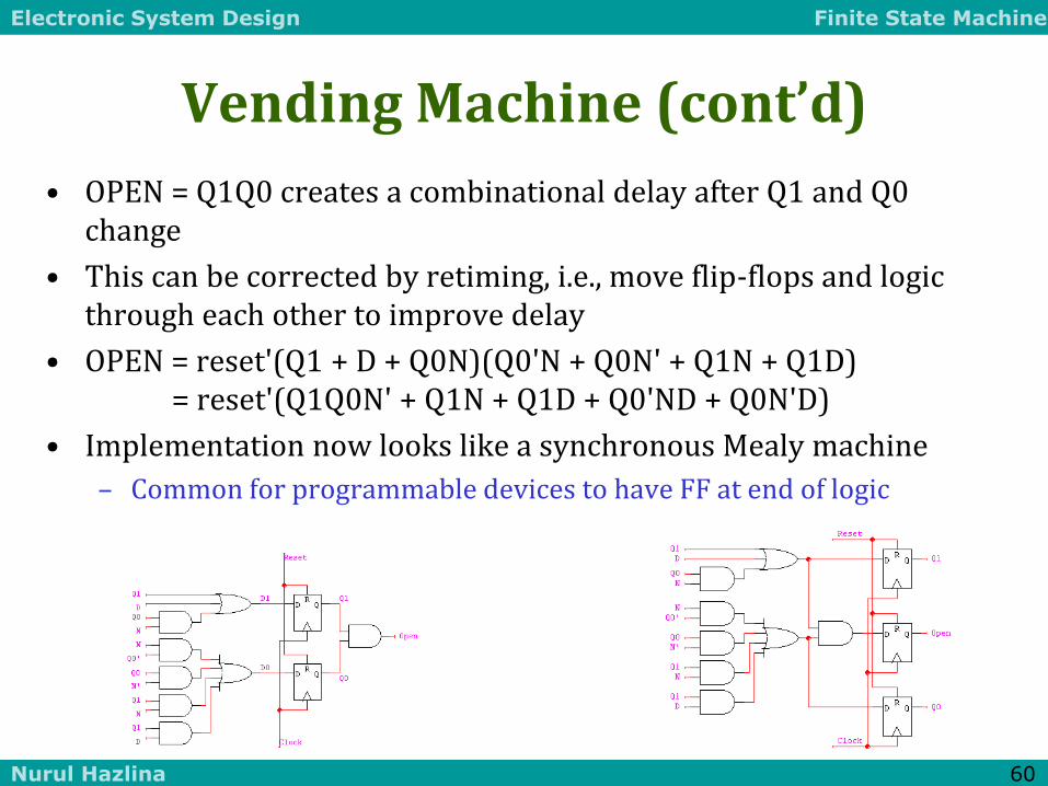
• OPEN = Q1Q0 creates a combinational delay after Q1 and Q0 change
• This can be corrected by retiming, i.e., move flip-flops and logic through each other to improve delay
• OPEN = reset'(Q1 + D + Q0N)(Q0'N + Q0N' + Q1N + Q1D) = reset'(Q1Q0N' + Q1N + Q1D + Q0'ND + Q0N'D)
• Implementation now looks like a synchronous Mealy machine
– Common for programmable devices to have FF at end of logic
Electronic System Design Finite State Machine
Nurul Hazlina 61
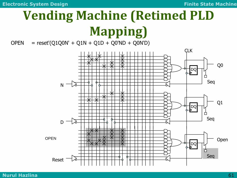
Vending Machine (Retimed PLD Mapping)
OPEN = reset'(Q1Q0N' + Q1N + Q1D + Q0'ND + Q0N'D)
OPEN
D Q
D Q
D Q
Q0
Q1
Open
Seq
Seq
Seq
CLK
N
D
Reset
Electronic System Design Finite State Machine
Nurul Hazlina 62
STATE MINIMIZATION

Electronic System Design Finite State Machine
Nurul Hazlina 63
Finite State Machine Optimization
• Should look over this one
• Make sure you know the motivation for this
– State Minimization
• Try to merge state with same behavior so total # of states are less
– State Encoding
• Less combinational logic involved in implementing if correct state encoding is chosen.
• Less Flip flops used if a more dense encoding is used.
– # of flip flop could range from log2(n) to n
• Make sure you know the algorithm for both

Electronic System Design Finite State Machine
Nurul Hazlina 64
Finite State Machine Optimization
• State Minimization
– Fewer states require fewer state bits
– Fewer bits require fewer logic equations
• Encodings: State, Inputs, Outputs
– State encoding with fewer bits has fewer equations to implement
• However, each may be more complex
– State encoding with more bits (e.g., one-hot) has simpler equations
• Complexity directly related to complexity of state diagram
– Input/output encoding may or may not be under designer control

Electronic System Design Finite State Machine
Nurul Hazlina 65
Algorithmic Approach to State Minimization
• Goal – identify and combine states that have equivalent behavior
• Equivalent States:
– Same output
– For all input combinations, states transition to same or equivalent states
• Algorithm Sketch
– 1. Place all states in one set
– 2. Initially partition set based on output behavior
– 3. Successively partition resulting subsets based on next state transitions
– 4. Repeat (3) until no further partitioning is required
• states left in the same set are equivalent
– Polynomial time procedure

Electronic System Design Finite State Machine
Nurul Hazlina 66
NurulHazlina/BEE2243/FSM
State Minimization
2 Methods:
1. Row Matching
2. Implication Chart
Electronic System Design Finite State Machine
Nurul Hazlina 67
NurulHazlina/BEE2243/FSM
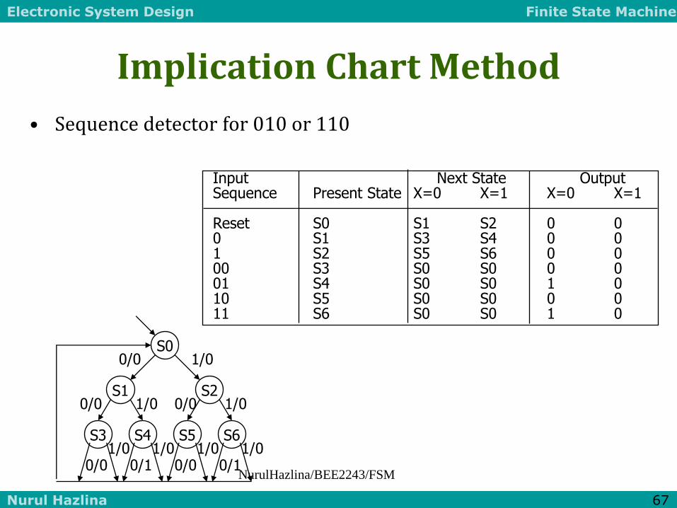
Input Next State Output Sequence Present State X=0 X=1 X=0 X=1 Reset S0 S1 S2 0 0 0 S1 S3 S4 0 0 1 S2 S5 S6 0 0 00 S3 S0 S0 0 0 01 S4 S0 S0 1 0 10 S5 S0 S0 0 0 11 S6 S0 S0 1 0
Implication Chart Method
• Sequence detector for 010 or 110
S0
S3
S2 S1
S5 S6 S4
1/0 0/0
1/0
1/0 0/1
0/0 1/0 0/0
1/0 0/0
1/0 0/1
1/0 0/0
Electronic System Design Finite State Machine
Nurul Hazlina 68
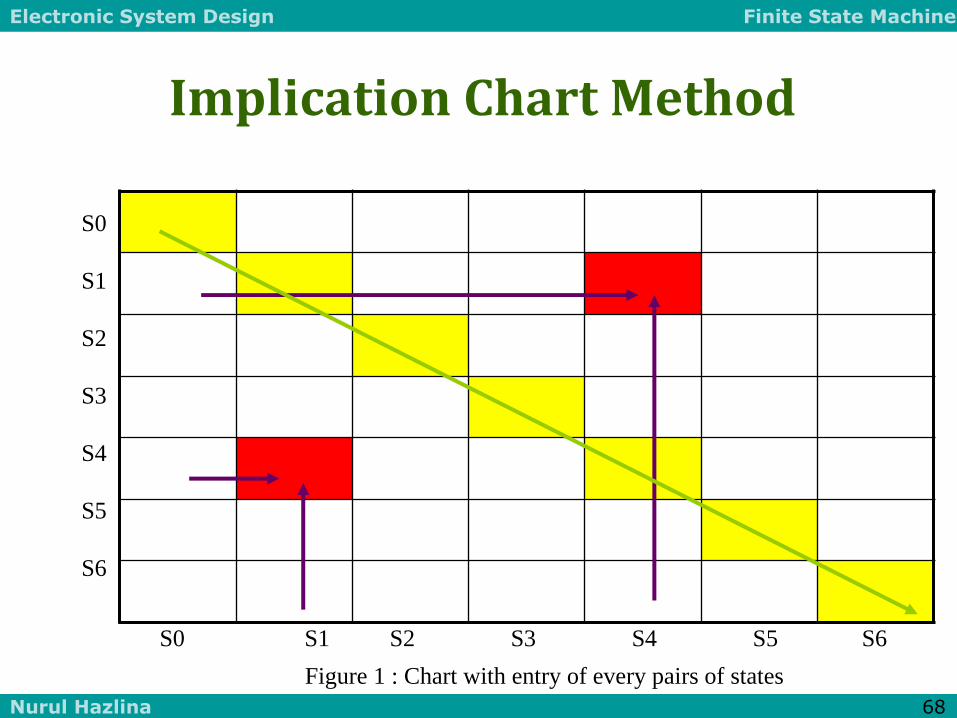
Implication Chart Method
Figure 1 : Chart with entry of every pairs of states
S0
S1
S2
S3
S4
S5
S6
S0 S1 S2 S3 S4 S5 S6

Electronic System Design Finite State Machine
Nurul Hazlina 69
Implication Chart Method
S0
S1
S2
S3
S4
S5
S6
S0 S1 S2 S3 S4 S5 S6

Electronic System Design Finite State Machine
Nurul Hazlina 70
NurulHazlina/BEE2243/FSM
Implication Chart Method
X X X X X
X
X X X X
S0, S1, S2, S3, S5same output (group1)
S4, S6 same output (group2) any combination across g1 and g2 indicate by X
S1-S3
S2-S4
S1-S5
S2-S6
S1-S0
S2-S0
S0-S0
S0-S0
S3-S5
S4-S6
S3-S0
S4-S0
IMPLIED
STATE
PAIRS
S5-S0
S6-S0
S1-S0
S2-S0
S3-S0
S4-S0
S5-S0
S6-S0
S0-S0
S0-S0
S0
S1
S2
S3
S4
S5
S6
S0 S1 S2 S3 S4 S5 S6
Electronic System Design Finite State Machine
Nurul Hazlina 71
NurulHazlina/BEE2243/FSM
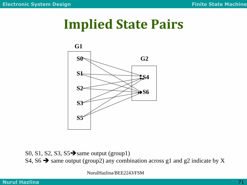
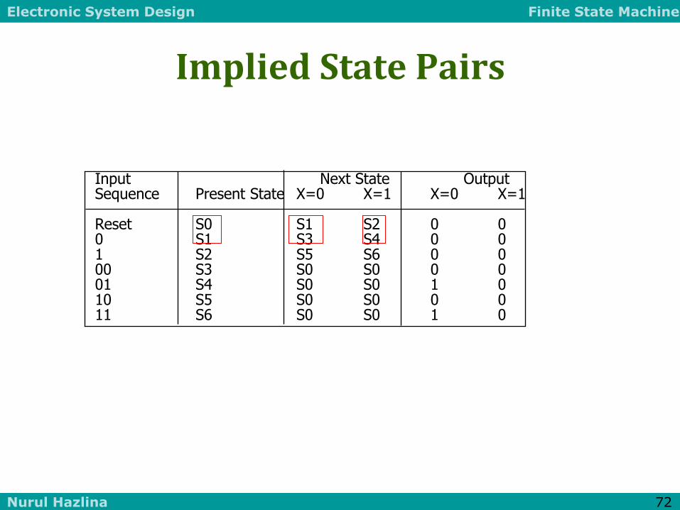
Implied State Pairs
S0, S1, S2, S3, S5same output (group1)
S4, S6 same output (group2) any combination across g1 and g2 indicate by X
S0
S1
S2
S3
S5
S4
S6
G1
G2
Electronic System Design Finite State Machine
Nurul Hazlina 72
Implied State Pairs
Input Next State Output Sequence Present State X=0 X=1 X=0 X=1 Reset S0 S1 S2 0 0 0 S1 S3 S4 0 0 1 S2 S5 S6 0 0 00 S3 S0 S0 0 0 01 S4 S0 S0 1 0 10 S5 S0 S0 0 0 11 S6 S0 S0 1 0

Electronic System Design Finite State Machine
Nurul Hazlina 73
NurulHazlina/BEE2243/FSM
Rechecked Implied State Pairs
X X X X X
X X X X
X X X X
X X X
X
X
IF square Si and Sj contains the ISP Sm-Sn and square Sm,Sn contains an X, then
Mark Si,Sj with an X as well.
S0-S0
S0-S0
S3-S5
S4-S6
S0-S0
S0-S0
S0 S1 S2 S3 S4 S5 S6
S0
S1
S2
S3
S4
S5
S6

Electronic System Design Finite State Machine
Nurul Hazlina 74
Implication Chart Method
Input Next State Output Sequence Present State X=0 X=1 X=0 X=1 Reset S0 S1' S1' 0 0 0 + 1 S1' S3' S4' 0 0 X0 S3' S0 S0 0 0 X1 S4' S0 S0 1 0
S0
S1’
S3’ S4’
X/0
1/0
1/0 0/1
0/0
X/0
Simplified Table

Electronic System Design Finite State Machine
Nurul Hazlina 75
NurulHazlina/BEE2243/FSM
Another Example
G
[0]
A
[0]
B
[0]
C
[0]
D
[1] E
[0]
F
[0] 1
1
1
1
1
1
0
0
0
0
0
1
0 0

Electronic System Design Finite State Machine
Nurul Hazlina 76 NurulHazlina/BEE2243/FSM
Continue
Present
state
Next state
0 1
output
A B C 0
B A C 0
C D C 0
D D E 1
E A F 0
F B G 0
G A E 0
Divide into 2 groups;
A,B,C,E,F,G and D based on
Output value

Electronic System Design Finite State Machine
Nurul Hazlina 77
State Minimization Example
• Sequence Detector for 010 or 110
Input Next State Output Sequence Present State X=0 X=1 X=0 X=1 Reset S0 S1 S2 0 0 0 S1 S3 S4 0 0 1 S2 S5 S6 0 0 00 S3 S0 S0 0 0 01 S4 S0 S0 1 0 10 S5 S0 S0 0 0 11 S6 S0 S0 1 0
S0
S3
S2 S1
S5 S6 S4
1/0 0/0
1/0
1/0 0/1
0/0 1/0 0/0
1/0 0/0
1/0 0/1
1/0 0/0

Electronic System Design Finite State Machine
Nurul Hazlina 78
Method of Successive Partitions Row Matching
( S0 S1 S2 S3 S4 S5 S6 )
( S0 S1 S2 S3 S5 ) ( S4 S6 )
( S0 S3 S5 ) ( S1 S2 ) ( S4 S6 )
( S0 ) ( S3 S5 ) ( S1 S2 ) ( S4 S6 )
Input Next State Output Sequence Present State X=0 X=1 X=0 X=1 Reset S0 S1 S2 0 0 0 S1 S3 S4 0 0 1 S2 S5 S6 0 0 00 S3 S0 S0 0 0 01 S4 S0 S0 1 0 10 S5 S0 S0 0 0 11 S6 S0 S0 1 0
S1 is equivalent to S2
S3 is equivalent to S5
S4 is equivalent to S6
Electronic System Design Finite State Machine
Nurul Hazlina 79
Minimized FSM
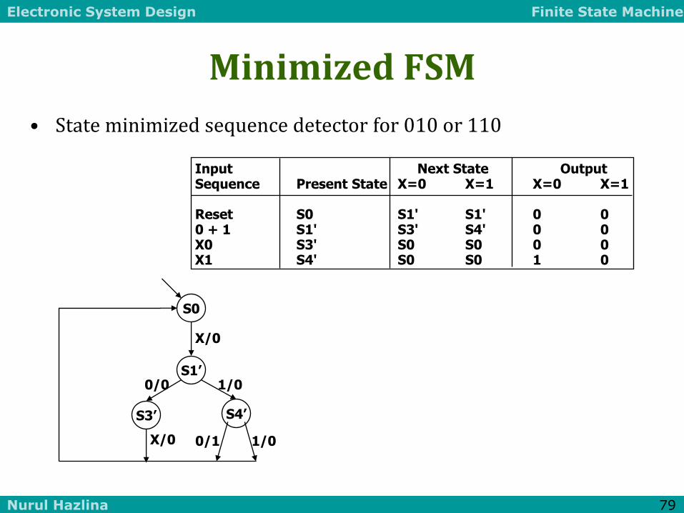
• State minimized sequence detector for 010 or 110
Input Next State Output Sequence Present State X=0 X=1 X=0 X=1 Reset S0 S1' S1' 0 0 0 + 1 S1' S3' S4' 0 0 X0 S3' S0 S0 0 0 X1 S4' S0 S0 1 0
S0
S1’
S3’ S4’
X/0
1/0
1/0 0/1
0/0
X/0

Electronic System Design Finite State Machine
Nurul Hazlina 80
Implication Chart

Electronic System Design Finite State Machine
Nurul Hazlina 81
More Complex State Minimization
• Multiple input example
symbolic state transition table
present next state output state 00 01 10 11 S0 S0 S1 S2 S3 1 S1 S0 S3 S1 S4 0 S2 S1 S3 S2 S4 1 S3 S1 S0 S4 S5 0 S4 S0 S1 S2 S5 1 S5 S1 S4 S0 S5 0
inputs here
10
01
11
00
00
01
11 10
10
01
11 00
10
00
11
00
11 10
01
10
11 01
00
S0 [1]
S2 [1]
S4 [1]
S1 [0]
S3 [0]
S5 [0]
01
Electronic System Design Finite State Machine
Nurul Hazlina 82
Minimized FSM
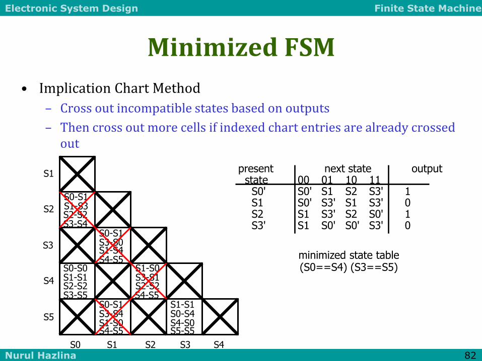
• Implication Chart Method
– Cross out incompatible states based on outputs
– Then cross out more cells if indexed chart entries are already crossed out
S0-S1 S1-S3 S2-S2 S3-S4
S0-S0 S1-S1 S2-S2 S3-S5
S0-S1 S3-S0 S1-S4 S4-S5
S0-S1 S3-S4 S1-S0 S4-S5
S1-S0 S3-S1 S2-S2 S4-S5
S4-S0 S5-S5
S1-S1 S0-S4
minimized state table (S0==S4) (S3==S5)
present next state output state 00 01 10 11 S0' S0' S1 S2 S3' 1 S1 S0' S3' S1 S3' 0 S2 S1 S3' S2 S0' 1 S3' S1 S0' S0' S3' 0
S1
S2
S3
S4
S5
S0 S1 S2 S3 S4

Electronic System Design Finite State Machine
Nurul Hazlina 83
Minimizing Incompletely Specified FSMs
• Equivalence of states is transitive when machine is fully specified
• But its not transitive when don't cares are present e.g., state output S0 – 0 S1 is compatible with both S0 and S2 S1 1 – but S0 and S2 are incompatible S2 – 1
• No polynomial time algorithm exists for determining best grouping of states into equivalent sets that will yield the smallest number of final states

Electronic System Design Finite State Machine
Nurul Hazlina 84
Minimizing States May Not Yield Best Circuit
• Example: edge detector - outputs 1 when last two input changes from 0 to 1
X Q1 Q0 Q1+ Q0
+
0 0 0 0 0
0 0 1 0 0
0 1 1 0 0
1 0 0 0 1
1 0 1 1 1
1 1 1 1 1
– 1 0 0 0
Q1+ = X (Q1 xor Q0)
Q0+ = X Q1’ Q0’
00 [0]
11 [0]
01 [1] X’
X’
X’
X
X
X
Electronic System Design Finite State Machine
Nurul Hazlina 85
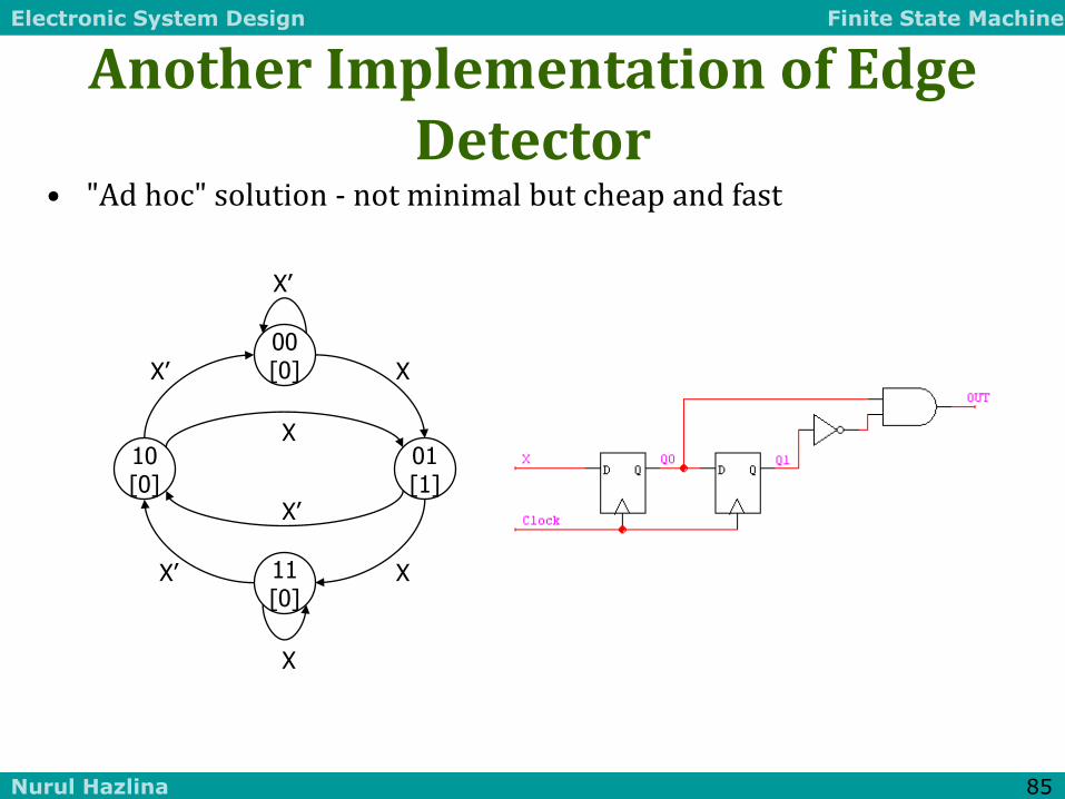
Another Implementation of Edge Detector
• "Ad hoc" solution - not minimal but cheap and fast
00 [0]
10 [0]
01 [1]
X’ X
X’
X
X
X 11 [0]
X’
X’

Electronic System Design Finite State Machine
Nurul Hazlina 86
Sequential Logic Implementation Summary
• Models for representing sequential circuits
– Abstraction of sequential elements
– Finite state machines and their state diagrams
– Inputs/outputs
– Mealy, Moore, and synchronous Mealy machines
• Finite state machine design procedure
– Deriving state diagram
– Deriving state transition table
– Determining next state and output functions
– Implementing combinational logic
• Implementation of sequential logic
– State minimization
– State assignment
– Support in programmable logic devices

Electronic System Design Finite State Machine
Nurul Hazlina 87
SEQUENTIAL LOGIC EXAMPLES
Finite State Machine Concept
FSMs are the decision making logic of digital designs
Partitioning designs into datapath and control elements
When inputs are sampled and outputs asserted
Basic Design Approach: 4-step Design Process
Implementation Examples and Case Studies
Finite-string pattern recognizer – mini project a
Traffic light controller – mini project b
Door combination lock – mini project c

Electronic System Design Finite State Machine
Nurul Hazlina 88
General FSM Design Procedure
1. Determine inputs and outputs
2. Determine possible states of machine
– State minimization
3. Encode states and outputs into a binary code
– State assignment or state encoding
– Output encoding
– Possibly input encoding (if under our control)
4. Realize logic to implement functions for states and outputs
– Combinational logic implementation and optimization
– Choices in steps 2 and 3 have large effect on resulting logic
Electronic System Design Finite State Machine
Nurul Hazlina 89
Finite String Pattern Recognizer (Step 1)
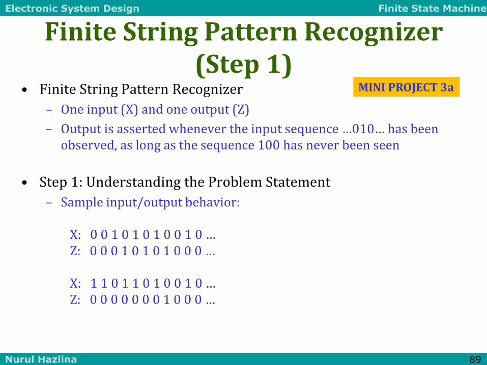
• Finite String Pattern Recognizer
– One input (X) and one output (Z)
– Output is asserted whenever the input sequence …010… has been observed, as long as the sequence 100 has never been seen
• Step 1: Understanding the Problem Statement
– Sample input/output behavior: X: 0 0 1 0 1 0 1 0 0 1 0 … Z: 0 0 0 1 0 1 0 1 0 0 0 … X: 1 1 0 1 1 0 1 0 0 1 0 … Z: 0 0 0 0 0 0 0 1 0 0 0 …
MINI PROJECT 3a
Electronic System Design Finite State Machine
Nurul Hazlina 90
Finite String Pattern Recognizer (Step 2)
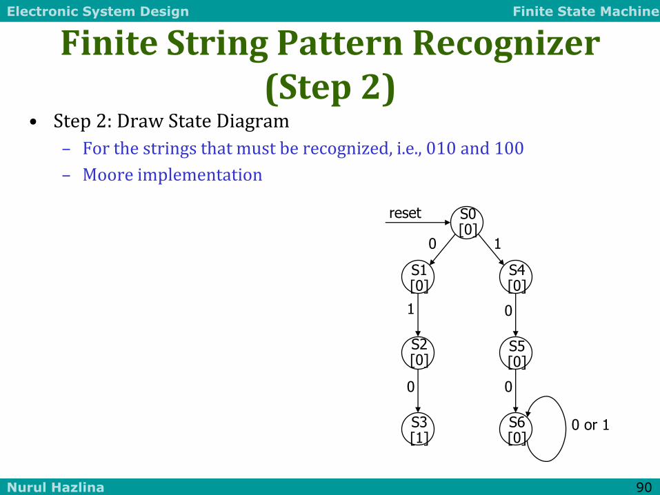
• Step 2: Draw State Diagram
– For the strings that must be recognized, i.e., 010 and 100
– Moore implementation
S1 [0]
S2 [0]
0
1
S3 [1]
0
S4 [0]
1
0 or 1
S5 [0]
0
0
S6 [0]
S0 [0]
reset

Electronic System Design Finite State Machine
Nurul Hazlina 91
Finite String Pattern Recognizer (Step 2, cont’d)
• Exit conditions from state S3: have recognized …010
– If next input is 0 then have …0100 = ...100 (state S6)
– If next input is 1 then have …0101 = …01 (state S2)
1
...01
...010 ...100
S4 [0]
S1 [0]
S0 [0]
S2 [0]
1 0
1
reset
0 or 1 S3 [1]
0
S5 [0]
0
0
S6 [0]
Exit conditions from S1: recognizes strings of form …0 (no 1 seen); loop back to S1 if input is 0 Exit conditions from S4: recognizes strings of form …1 (no 0 seen); loop back to S4 if input is 1
...1 ...0 1 0

Electronic System Design Finite State Machine
Nurul Hazlina 92
Finite String Pattern Recognizer (Step 2, cont’d)
• S2 and S5 still have incomplete transitions
– S2 = …01; If next input is 1, then string could be prefix of (01)1(00) S4 handles just this case
– S5 = …10; If next input is 1, then string could be prefix of (10)1(0) S2 handles just this case
• Reuse states as much as possible
– Look for same meaning
– State minimization leads to smaller number of bits to represent states
• Once all states have complete set of transitions we have final state diagram
1
...01
...010 ...100
S4 [0]
S1 [0]
S0 [0]
S2 [0]
1 0
1
reset
0 or 1 S3 [1]
0
S5 [0]
0
0
S6 [0]
...1 ...0 1 0
...10
1
1
Electronic System Design Finite State Machine
Nurul Hazlina 93
Finite String Pattern Recognizer
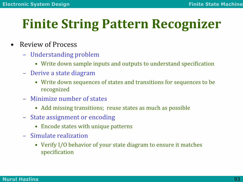
• Review of Process
– Understanding problem
• Write down sample inputs and outputs to understand specification
– Derive a state diagram
• Write down sequences of states and transitions for sequences to be recognized
– Minimize number of states
• Add missing transitions; reuse states as much as possible
– State assignment or encoding
• Encode states with unique patterns
– Simulate realization
• Verify I/O behavior of your state diagram to ensure it matches specification

Electronic System Design Finite State Machine
Nurul Hazlina 94
Traffic Light Controller as Two Communicating FSMs
• Without Separate Timer
– S0 would require 7 states
– S1 would require 3 states
– S2 would require 7 states
– S3 would require 3 states
– S1 and S3 have simple transformation
– S0 and S2 would require many more arcs
• C could change in any of seven states
• By Factoring Out Timer
– Greatly reduce number of states
• 4 instead of 20
– Counter only requires seven or eight states
• 12 total instead of 20
TS/ST
S1
TS'
–/ST
S1a
S1b
S1c
traffic light
controller
timer
TL TS ST
MINI PROJECT 3b
Electronic System Design Finite State Machine
Nurul Hazlina 95
Communicating Finite State Machines
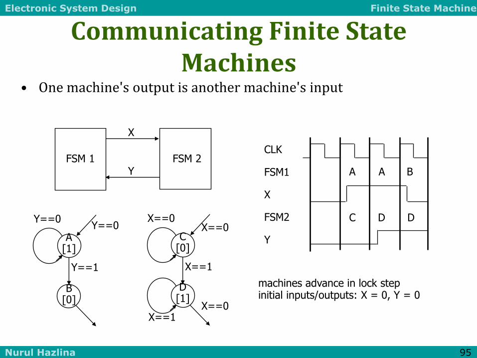
• One machine's output is another machine's input
machines advance in lock step initial inputs/outputs: X = 0, Y = 0
CLK FSM1 X FSM2 Y
A A B
C D D
FSM 1 FSM 2
X
Y
Y==1
A [1]
Y==0
B [0]
Y==0
X==1
C [0]
X==0 X==0
D [1]
X==1 X==0
Electronic System Design Finite State Machine
Nurul Hazlina 96
Datapath and Control
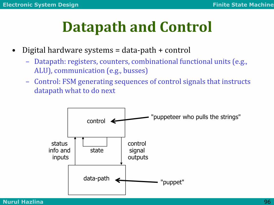
• Digital hardware systems = data-path + control
– Datapath: registers, counters, combinational functional units (e.g., ALU), communication (e.g., busses)
– Control: FSM generating sequences of control signals that instructs datapath what to do next
"puppet"
"puppeteer who pulls the strings" control
data-path
status info and inputs
control signal outputs
state

Electronic System Design Finite State Machine
Nurul Hazlina 97
Digital Combinational Lock
• Door Combination Lock:
– Punch in 3 values in sequence and the door opens; if there is an error the lock must be reset; once the door opens the lock must be reset
– Inputs: sequence of input values, reset
– Outputs: door open/close
– Memory: must remember combination or always have it available
– Open questions: how do you set the internal combination?
• Stored in registers (how loaded?)
• Hardwired via switches set by user
MINI PROJECT 3c

Electronic System Design Finite State Machine
Nurul Hazlina 98
Determining Details of the Specification
• How many bits per input value?
• How many values in sequence?
• How do we know a new input value is entered?
• What are the states and state transitions of the system?
reset value
open/closed
new
clock

Electronic System Design Finite State Machine
Nurul Hazlina 99
Digital Combination Lock State Diagram
• States: 5 states
– Represent point in execution of machine
– Each state has outputs
• Transitions: 6 from state to state, 5 self transitions, 1 global
– Changes of state occur when clock says its ok
– Based on value of inputs
• Inputs: reset, new, results of comparisons
• Output: open/closed
closed closed closed C1==value
& new C2==value
& new C3==value
& new
C1!=value & new
C2!=value & new
C3!=value & new
closed
reset
not new not new not new
S1 S2 S3 OPEN
ERR
open

Electronic System Design Finite State Machine
Nurul Hazlina 100
Datapath and Control Structure
• Datapath
– Storage registers for combination values
– Multiplexer
– Comparator
• Control
– Finite-state machine controller
– Control for data-path (which value to compare)
reset
open/closed
new C1 C2 C3
comparator value equal
multiplexer
controller
mux control
clock 4
4 4 4
4

Electronic System Design Finite State Machine
Nurul Hazlina 101
State Table for Combination Lock
• Finite-State Machine
– Refine state diagram to take internal structure into account
– State table ready for encoding
reset new equal state state mux open/closed 1 – – – S1 C1 closed 0 0 – S1 S1 C1 closed 0 1 0 S1 ERR – closed
0 1 1 S1 S2 C2 closed ... 0 1 1 S3 OPEN – open ...
next
Electronic System Design Finite State Machine
Nurul Hazlina 102
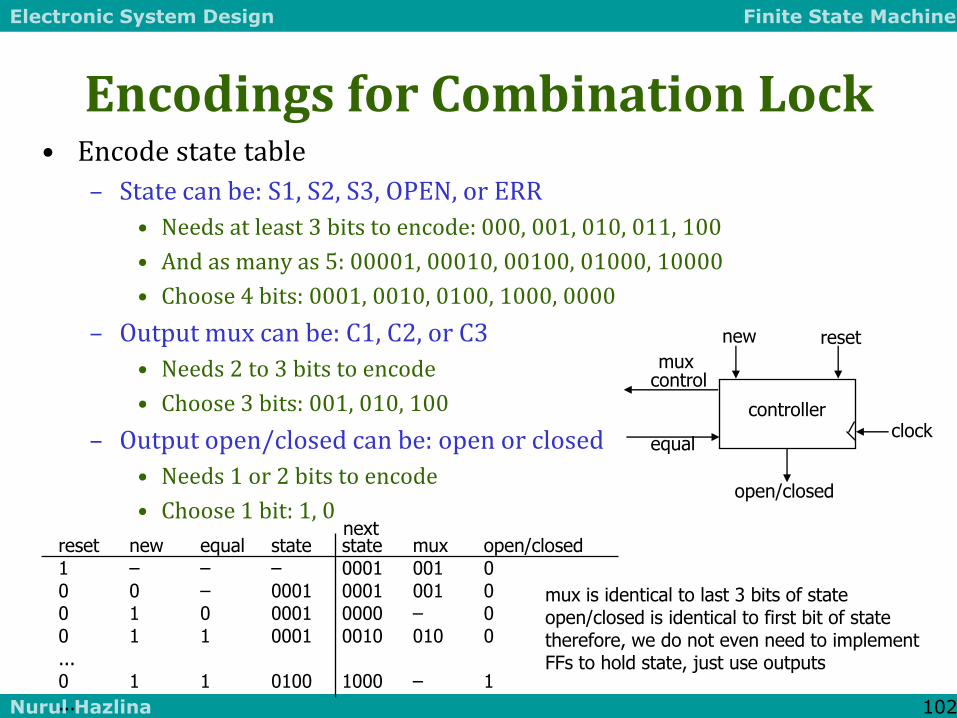
Encodings for Combination Lock • Encode state table
– State can be: S1, S2, S3, OPEN, or ERR
• Needs at least 3 bits to encode: 000, 001, 010, 011, 100
• And as many as 5: 00001, 00010, 00100, 01000, 10000
• Choose 4 bits: 0001, 0010, 0100, 1000, 0000
– Output mux can be: C1, C2, or C3
• Needs 2 to 3 bits to encode
• Choose 3 bits: 001, 010, 100
– Output open/closed can be: open or closed
• Needs 1 or 2 bits to encode
• Choose 1 bit: 1, 0
reset new equal state state mux open/closed 1 – – – 0001 001 0
0 0 – 0001 0001 001 0 0 1 0 0001 0000 – 0 0 1 1 0001 0010 010 0 ... 0 1 1 0100 1000 – 1 ...
next
mux is identical to last 3 bits of state open/closed is identical to first bit of state therefore, we do not even need to implement FFs to hold state, just use outputs
reset
open/closed
new
equal
controller
mux control
clock

Electronic System Design Finite State Machine
Nurul Hazlina 103
Datapath Implementation for Combination Lock
• Multiplexer
– Easy to implement as combinational logic when few inputs
– Logic can easily get too big for most PLDs
C1 C2 C3
comparator equal
multiplexer
mux control
4
4 4 4
4
value
C1i C2i C3i
mux control
value
equal
Electronic System Design Finite State Machine
Nurul Hazlina 104
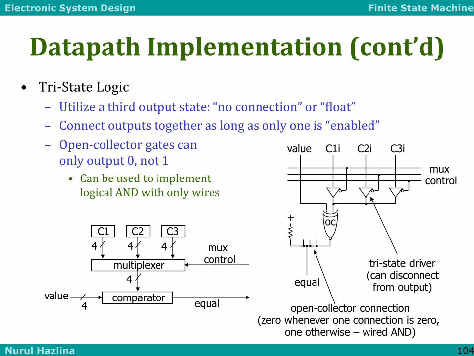
Datapath Implementation (cont’d)
• Tri-State Logic
– Utilize a third output state: “no connection” or “float”
– Connect outputs together as long as only one is “enabled”
– Open-collector gates can only output 0, not 1
• Can be used to implement logical AND with only wires
C1 C2 C3
comparator equal
multiplexer
mux control
4
4 4 4
4
value
C1i C2i C3i
mux control
value
equal
+ oc
open-collector connection (zero whenever one connection is zero,
one otherwise – wired AND)
tri-state driver (can disconnect
from output)
Electronic System Design Finite State Machine
Nurul Hazlina 105
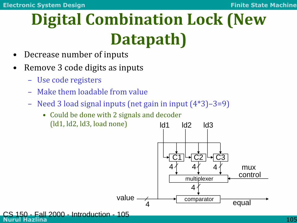
Digital Combination Lock (New Datapath)
• Decrease number of inputs
• Remove 3 code digits as inputs
– Use code registers
– Make them loadable from value
– Need 3 load signal inputs (net gain in input (4*3)–3=9)
• Could be done with 2 signals and decoder (ld1, ld2, ld3, load none)
CS 150 - Fall 2000 - Introduction - 105
C1 C2 C3
comparator value equal
multiplexer
mux control
4
4 4 4
4
ld1 ld2 ld3

Electronic System Design Finite State Machine
Nurul Hazlina 106
Section Summary
• FSM Design
– Understanding the problem
– Generating state diagram
– Implementation using synthesis tools
– Iteration on design/specification to improve qualities of mapping
– Communicating state machines
• Four case studies
– Understand I/O behavior
– Draw diagrams
– Enumerate states for the "goal"
– Expand with error conditions
– Reuse states whenever possible
Electronic System Design Finite State Machine
Nurul Hazlina 107
FSM AND HDL

Electronic System Design Finite State Machine
Nurul Hazlina 108
Hardware Description Languages and Sequential Logic
• Flip-flops
– representation of clocks - timing of state changes
– asynchronous vs. synchronous
• FSMs
– structural view (FFs separate from combinational logic)
– behavioral view (synthesis of sequencers – not in this course)
• Data-paths = data computation (e.g., ALUs, comparators) + registers
– use of arithmetic/logical operators
– control of storage elements
Electronic System Design Finite State Machine
Nurul Hazlina 109
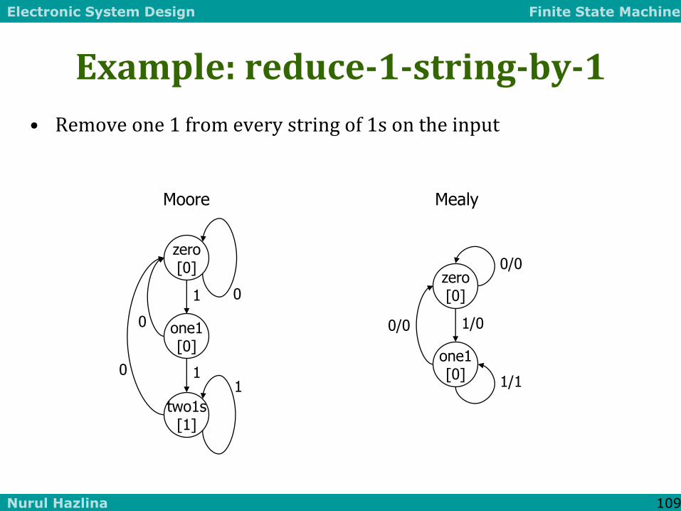
Example: reduce-1-string-by-1
• Remove one 1 from every string of 1s on the input
1
0
0
0
1 1
zero [0]
one1 [0]
two1s [1]
1/0 0/0
0/0
1/1
zero [0]
one1 [0]
Moore Mealy
Electronic System Design Finite State Machine
Nurul Hazlina 110
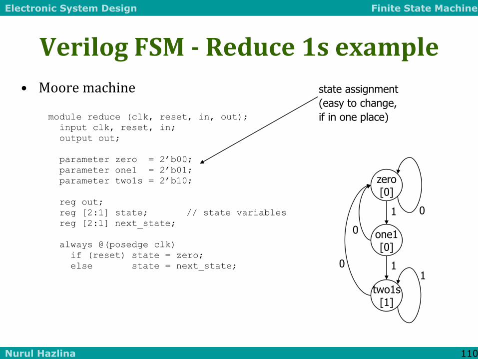
module reduce (clk, reset, in, out);
input clk, reset, in;
output out;
parameter zero = 2’b00;
parameter one1 = 2’b01;
parameter two1s = 2’b10;
reg out;
reg [2:1] state; // state variables
reg [2:1] next_state;
always @(posedge clk)
if (reset) state = zero;
else state = next_state;
state assignment
(easy to change,
if in one place)
Verilog FSM - Reduce 1s example
• Moore machine
1
0
0
0
1 1
zero [0]
one1 [0]
two1s [1]

Electronic System Design Finite State Machine
Nurul Hazlina 111
always @(in or state)
case (state)
zero:
// last input was a zero
begin
if (in) next_state = one1;
else next_state = zero;
end
one1:
// we've seen one 1
begin
if (in) next_state = two1s;
else next_state = zero;
end
two1s:
// we've seen at least 2 ones
begin
if (in) next_state = two1s;
else next_state = zero;
end
endcase
crucial to include
all signals that are
input to state determination
Moore Verilog FSM (cont’d)
note that output
depends only on state
always @(state)
case (state)
zero: out = 0;
one1: out = 0;
two1s: out = 1;
endcase
endmodule

Electronic System Design Finite State Machine
Nurul Hazlina 112
module reduce (clk, reset, in, out);
input clk, reset, in;
output out;
reg out;
reg state; // state variables
reg next_state;
always @(posedge clk)
if (reset) state = zero;
else state = next_state;
always @(in or state)
case (state)
zero: // last input was a zero
begin
out = 0;
if (in) next_state = one;
else next_state = zero;
end
one: // we've seen one 1
if (in) begin
next_state = one; out = 1;
end else begin
next_state = zero; out = 0;
end
endcase
endmodule
Mealy Verilog FSM
1/0 0/0
0/0
1/1
zero [0]
one1 [0]

Electronic System Design Finite State Machine
Nurul Hazlina 113
module reduce (clk, reset, in, out);
input clk, reset, in;
output out;
reg out;
reg state; // state variables
always @(posedge clk)
if (reset) state = zero;
else
case (state)
zero: // last input was a zero
begin
out = 0;
if (in) state = one;
else state = zero;
end
one: // we've seen one 1
if (in) begin
state = one; out = 1;
end else begin
state = zero; out = 0;
end
endcase
endmodule
Synchronous Mealy Machine