Embed Size (px)
Citation preview

2
FINITE STATE MACHINE
2.1 AUTOMATA
An automaton is a mathematical model of a system withdiscrete inputs and discrete outputs. The system is a controlunit, which can be any one of a finite number of internal statesand which can change states in some defined manner. TheFig. 2.1 shows a general representation of an automaton. Theinput is a string over a given alphabet written on an input file;which the automata can read but cannot change. The input fileis divided into set of cells where each cell contains onesymbol at a time and also read the input file left to right onesymbol at a time. It also detects the end of the input string byusing specific symbol (i.e. write end marker). The output isalso a string of some form. It may have a temporary storagedevice, consisting of an unlimited number of cells, each cellcontaining a single symbol from an alphabet (cell can containsame or different symbols).
An automaton is used to operate discrete timeframe. At any given time, the system is in some internalstate and the input is scanning a particular symbol on the input file. The internal state of the system atthe next time step is determined by the next state or transition system. This transition system gives thenext state in terms of the current state, the current input symbol and the information currently in thetemporary storage. During the transition from one state to next state the output may be produced orthe information in the temporary storage changed depending upon the designed machine. The transitionfrom one state to another state is called move.
2.2 DETERMINISTIC FINITE AUTOMATON (DFA)
A DFA consists of following three things1. A finite set of states, one of which is designed as the initial state, called the starting state and
some (may be none) of which are designed as final states.2. An input alphabet ∑.3. A transition system (i.e. transition graph, transition table or transition function) that tells for each
state and each letter of the input alphabet, the state to which to go next.
or Mathematically a DFA is given by M = (Q, ∑, δ, q0, F)1. Q is a finite non empty set of states.2. ∑ is a finite non empty set of input symbols.
Fig. 2.1
2.1

2.2 THEORY OF AUTOMATA AND FORMAL LANGUAGES
3. δ is a transition system and δ ∈ Q × ∑→ Q4. q0 is an initial state and q0 ∈ Q5. F is a set of accepting states (or final states) and F ⊆ Q
The above definition describes the composition of a DFA but not how it works. It works by beingpresented with an input string of letters that it reads letter by letter starting at the leftmost letter.Beginning at the starting state, the letters determine a sequence of states. The sequence of states endswhen the last input letter has been read and if the last state is an accepting (or final) state then thatstring is accepted by a DFA otherwise rejected.
2.2.1 TRANSITION SYSTEMA transition system can be represented in any one of the following three ways:● Transition graph ● Transition table ● Transition function.
(1) Transition graph: A transition graph is a finite directed labeled graph in which each vertex (ornode) represents a state and the directed edges indicate the transition of the state and the edges arelabelled with the input alphabet.
A transition graph is shown in Fig 2.2.In the Fig 2.2 the initial state isrepresented by a ring (or circle) withan arrow pointing towards it, the finalstate by two concentric rings (or circles)and the other states are represented byjust a ring (or circle). The edges arelabeled by input.
For example, in the Fig 2.2 state q0 is an initial state, q2 is a final state and q1 is another state, and thetransitions performed by these states are follows
From state q0 and input 0, go to the next state q1
From state q0 and input 1 go to the next state q0
From state q1 and input 0, go to the next state q1
From state q1 and input 1, go to the next state q2
From state q2 and input 0, go to the next state q2
From state q2 and input 1, go to the next state q2
(2) Transition Table: A DFA may be conveniently represented by a transition table. The transitiontable is a tabular representation of a machine. For example, the tabular representation of Fig. 2.2 isshown in table 1.
Table 1
The table represents the transition graph of δ i.e. to find the value of present state q and input alphabetx we have to look at the row labeled q and the column labeled x. The initial state is marked by an → andthe final state is marked by a single ring (or circle).
Fig. 2.2

FINITE STATE MACHINE 2.3
(3) Transition function: A DFA may also be represented by a transition function δ. The transitionfunction of Fig 2.2 can be represented as follows:
δ(q0, 0) = q1
δ(q0, 1) = q0
δ(q1, 0) = q1
δ(q1, 1) = q2
δ(q2, 0) = q2
δ(q2, 1) = q2
Here the first argument of transition function δ represents the present (current) state and secondargument represents the input letter and the right hand side represents the next state.
For example.
In the δ(q0, 0) = q1
q0 is a present state,
0 is an input alphabet
and q1 is a next state
Example 1: Consider the DFA machine M = ({q0, q1, q2}, {0,1}, δ, q0, {q2}) where a transition systemδ is defined in Fig. 2.2.
This represents a mathematical model of DFA machine where the tuples values are
Q = {q0, q1, q2}
∑ = {0, 1}
δ is shown in Fig 2.2
q0 is an initial state
q2 is a final state
Language of a DFA
To each DFA machine M we associate a language L(M) ⊆ ∑*. To see whether a word w∈ L(M), we puta marker in the initial state and after reading a symbol move forward the marker along the edge markedwith this symbol. If we reach the accepting state at the end of the word w, then w ∈ L(M), otherwisew ∉ L(M).
In the above example we have 0 ∉ L(M), 101∈ L(M) and 1101 ∈ L(M). Indeed we have,L(M) = {w|w contains the substring 01}.
To be more precise we give a formal definition of L(M). First we define the entered transition functionδ ∈ Q × ∑* → Q. Intuitively, δ(q, w)=q′ if starting from state q we end up in state q′ when reading theword w formally, δ is defined by following rules:
Rule 1 δ{q, ∈ } = q
Rule 2 δ{q, xw} = δ {δ(q, x), w}
Here xw stands for a non empty word whose first symbol is x and the rest is w i.e. x is a prefix ofword w. sometimes w may be empty.
For example
If xw = 010 then this entails that
x = 0 and w=10.

2.4 THEORY OF AUTOMATA AND FORMAL LANGUAGES
i.e. xw = 0 entails x = 0 and w = ∈As an example we calculate
δ(q0, 101) = q2 (Using Fig. 2.2)
Using δ we may now define formally
L(M) = {w | δ(q0, w) ∈ F}
Hence we have that 101 ∈ L(M) because
δ(q0, 101) = q2 and q2 ∈ F as shown below
δ(q0, 101) = δ(δ(q0, 1),01) by rule 2
= δ(q0, 01)
= δ(δ(q0, 0)1) by rule 2
= δ(q1, 1)
= δ(δ(q1, 1), ∈ ) by rule 2
= δ(q2, ∈ )
= q2 by rule 1
Acceptability of a language (or string) by a finite Automaton
A language (string) w is accepted by a finite automaton M = (Q, ∑, δ, q0, F) if δ(q0, w) = q for someq ∈ F.
Example 2: Consider the following DFA machine M = ({q0, q1, q2}, {0, 1}, δ, q0, {q1}) where atransition graph is shown in Fig. 2.3.
Fig. 2.3
Check if the string 00001 is accepted by DFA. Also find the sequence of states.
Solution: The given language is δ(q0, 00001)
= δ(δ(q0, 0), 0001) by rule 2
= δ(q0, 0001) from transition graph i.e. δ(q0, 0) = q0
= δ(δ(q0, 0), 001) by rule 2
= δ((q0, 001)
= δ(δ(q0, 0), 01) by rule 2
= δ(q0, 01)
= δ(δ(q0, 0), 1) by rule 2
= δ(q0, 1)
= δ(δ(q0, 1), ∈ ) by rule 2
= δ((q1, ∈ )
= q1 by rule 1
= q1 ∈∈∈∈∈ F
Hence the string is accepted by DFA machine.

FINITE STATE MACHINE 2.5
The sequence of states corresponding to the input symbol is given by
Example 3: Find the sequence of states corresponding to the input symbol 0000111 for the transitiondigraph shown in Fig. 2.3.
Solution: The sequence of states of input symbol 0000111 corresponding to the given transition digraphis given below:
Since q2 is not a final states, so the language 0000111 is not accepted by a DFA machine
Note: This DFA machine accepts all set of strings (or words) of the form {0n1| n ≥ 0 or 0*1}.
Example 4: Consider the following DFA machine M = ({q0, q1, q2, q3, q4, q5, q6}, {a, b}, δ, q0, {q5})where a transition graph is shown in Fig. 2.4.
Fig. 2.4
Check if the string babaa is accepted by DFA. Also find the sequence of states.
Solution: The given language is δ(q0, babaa)
= δ(δ(q0, b), abaa) by rule 2
= δ(q1, abaa) from transition graph i.e. δ(q0, b) = q1
= δ(δ(q1, a), baa) by rule 2
= δ((q2, baa)
= δ(δ(q2, b), aa) by rule 2
= δ(q3, aa)
= δ(δ(q3, a), a) by rule 2
= δ(q4, a)
= δ(δ(q4, a), ∈ ) by rule 2
= δ((q5, ∈ )
= q5 by rule 1
= q5 ∈∈∈∈∈ F
Hence the string is accepted by DFA machine.
The sequence of states corresponding to the input symbol is given by

2.6 THEORY OF AUTOMATA AND FORMAL LANGUAGES
Note: This machine accepts only one string i.e. babaa, no other string is accepted by this DFA machinebecause if you change the string (or word ), the sequence of state will reach on non final state.
Some basic concept to design a DFATo design a DFA machine we have to find our own logic but here we try to give some examples todevelop our logic for DFA machine. We know that the heart of DFA machine is transition system. Itmeans when we are able to design a transition system for any problem, we are able to design a DFAmachine.
Example 5: Find a DFA machine that accepts all the language (or strings) of a′s including ∈ overinput alphabet ∑={a}
Solution: The language contains only a of any length including ∈ i.e. the set of language looks as {∈ ,a , aa, aaa, aaaa, ……………..…..}. To design a DFA machine we use the following steps
Step 1: Let us consider an initial state say q0
Step 2: The language contains empty string (i.e.∈ ), so the initial and final state must be the samestates.
Step 3: Since the input symbol is a, then on initial state q0 ( or present state q0) and oninput symbol a the state will not change i.e. it will remain q0, which is a finalstate and transition diagram is as shown in Fig. 2.5
This transition digraph contain all five tuples value of a DFA machinei.e. (Q,∑,δ,q0, F).
So a DFA machine is ({q0}, {a}, δ, q0, {q0}) where δ is shown in Fig. 2.5.
Example 6: Find a DFA machine that accepts all the language( or string ) of a′s and b′s of any orderand of any length including ∈ over input alphabet ∑={a, b}
Solution: The language contains a and b of any order and of any length including ∈ i.e. the set oflanguage looks like as follows : {∈ , a ,b, aa, bb, ab, ba, aaa, abb, aab, bbb,baa, bba, aba,bab, ……………}.To design a DFA machine we use the following steps
Step 1: Let us consider an initial state say q0
Step 2: The language contains empty string (i.e.∈ ), so the initial and final states must be the samestates.
Step 3: Since the input symbols are a and b, then on initial state q0 (or presentstate q0) and on input symbol a and b the state will not change i.e. itwill remain q0, which is a final state and transition digraph is shown inFig. 2.6.
This transition digraph contains all five tuples value of a DFA machine i.e (Q,∑,δ,q0,F).
So a DFA machine is ({q0, {a, b}, δ,q0,{q0}) where δ is shown in Fig. 2.6.
Example 7: Find a DFA machine that accepts all language ( or strings ) that have exactly one 0 overinput alphabet ∑={0,1}
Solution: The language contains exactly one letter of 0 and the other letters may be only 1’s of anyorder and of any length either before 0 or after 0 or before and after both, including ∈ . So the set oflanguage looks as {0, 10, 01, 110, 011, 101,…………..}. To design a DFA machine we use thefollowing steps
Step 1: Let us consider an initial state say q0.
Fig. 2.5
Fig. 2.6

FINITE STATE MACHINE 2.7
Step 2: Since the first input symbol is either 0 or 1, then on initial state q0 (or present state q0) and oninput symbol 0 consider the next state i.e. q1 and on initial state q0 (or present state q0) and oninput symbol 1 the state will not change.
State 3: On state q1 the input symbol may be any onei.e. either 0 or 1. If input symbol is 1 then thenext state will not change i.e. it will remain q1which is a final state.
Step 4: On final state q1 if input symbol is 0 the stringwill not be accepted by DFA as the string tobe accepted contains one 0 only.
The transition digraph is shown in Fig. 2.7.
This transition digraph contain all five tuples value of a DFA machine i.e. (Q,∑,δ,q0,F).
So a DFA machine is ({q0, q1, q2}, {0,1}, δ, q0,{q1}) where δ is shown in Fig. 2.7.
Example 8: Find a DFA machine that accept all strings beginning with 0 over input alphabet ∑={0,1}
Solution: The language begins with letter 0 and the other letters may be of any order of 0’s and 1’s andof any length including ∈ . So the set of language look likes as follows {0, 00, 01, 000, 011,010,001,0000,0001,…………..}. To design a DFA machine we use the following steps:
Step 1: Let us consider an initial state say q0
Step 2: Since the first input symbol is 0 then on initial stateq0 ( or present state q0) and on input symbol 0consider the next state i.e. q1.
State 3: On state q1 the input symbol may be any one i.e.either 0 or 1. If input symbol is either 0 or 1 the nextstate will not change i.e. it will remain q1. It is a finalstate.
Step 4: On initial state q0 if input symbol is 1 the string willbe rejected by DFA. The transition digraph is shownin Fig. 2.8.
This transition digraph contain all five tuples value of a DFA machine i.e(Q,∑,δ,q0,F).
So a DFA machine is ({q0, q1, q2} {0,1}, δ,q0,{q1}) where δ is shown in Fig. 2.8.
Example 9: Find a DFA machine for the language L = { 0w0 : w∈ {0,1}* }
Solution: The language contains first and last letter as 0 and intermediate letters may be of any orderof 0′s and 1′s and of any length including ∈ i.e. the set of language looks as {00, 000, 010, 0000, 0010,0100,0110,…..}. To design a DFA machine we use the following steps
Step 1: Let us consider an initial state say q0
Step 2: Since the first input symbol is 0 then on initial state q0 ( or present state q0) and input symbol0 consider the next state as q1.
State 3: On state q1 the input symbol may be any one i.e. either 0 or 1 of any order and of any length.If input symbol is 0 then the next state is q2 which is a final state and if input symbol is 1 thenext state is q1 because 1 may be of any length.
Step 4: On state q2 if input symbol is 0 then the next state will not change i.e. it will remain q2 but ifinput symbol is 1 then the next state is q1
Step 5: On initial state q0 if input symbol is 1 the string will not be accepted by DFA.
Fig. 2.7
Fig. 2.8

2.8 THEORY OF AUTOMATA AND FORMAL LANGUAGES
The transition digraph is shown in Fig.2.9. This transition digraph contain all five tuples value of a DFAmachine i.e (Q,∑,δ,q0,F).So a DFA machine is ({q0, q1, q2,q3} {0,1}, δ,q0,{q3}) where δ is shown inFig. 2.9.
Fig. 2.9
Example 10: Find a DFA machine that accept all strings (or language ) having different first and lastletters over input alphabet ∑={a,b}
Solution: The DFA machine contains all strings whose first letter is different from the last letter i.e. iffirst letter is a then the last letter must be b or if first letter is b then the last letter must be a. In thislanguage (or strings) intermediate letters may be in any order and of any lengths. The transition digraphis shown in Fig.2.10. In this transition diagram if the read/ write head will read first letter the state willchange and if the next symbol is similar to first symbol the state will not change but if it is different, thestate will change as shown in Fig. 2.10.
Fig. 2.10
Hence the DFA machine is ({q0, q1, q2, q3, q4}, {a, b}, δ, q0,{q3,q4})})
Example 11: Find a DFA machine that accepts an even numberof either 0’s or 1’s or both 0′s and 1′s over input symbol ∑={0,1}.
[U.P.T.U., B.Tech., 2001-02]
Solution: The heart part δ (i.e. transition system) of DFAmachine is shown in Fig. 2.11
Hence a DFA machine is ({q1, q2, q3, q4}, {0, 1}, δ, q1, {q1})
Example 12: Find a DFA machine that accepts the language which has a sub-string 0101 over inputalphabet Σ = {0, 1}
Fig. 2.11
FINITE STATE MACHINE 2.9
Solution: The heart part δ (i.e. transition system) of DFA machine is shown in Fig.2.12.
Fig. 2.12
Hence a DFA machine is ({q1, q2, q3, q4, q5}, {0, 1}, δ, q1, {q5})
Example 13: Find a DFA machine that accepts the language which has either odd number of 0’s oreven number of 1’s but not both together over input alphabet Σ = {0, 1}Solution: The heart part (i.e. transition system) of DFA machine is shown in Fig.2.13.
Fig. 2.13
Hence a DFA machine is ({q1, q2, q3, q4}, {0, 1}, δ, q1, {q2, q4})
Example 14: Find a DFA machine that accepts the language which has both 01 and 10 as substringover input alphabet Σ = {0, 1}
Solution: The heart part (i.e. transition system) of DFA machine is shown in Fig. 2.14
Fig. 2.14
Hence a DFA machine is ({q1, q2, q3, q4, q5, q6, q7}, {0, 1}, δ, q1, {q4, q7})

2.10 THEORY OF AUTOMATA AND FORMAL LANGUAGES
Example 15: Find a DFA machine that accepts the language which has neither 00 nor 11 as a substringover input alphabet Σ = {0, 1}
Solution: The heart part (i.e. transition system) of DFA machine is shown in Fig. 2.15.
Fig. 2.15
Hence a DFA machine is ({q1, q2, q3, q4, q5}, {0, 1}, δ, q1, {q2, q3})
Example 16: Design a DFA machine that accept all strings with no more than five a’s over inputsymbol ∑ = {a, b}.
Solution: The transition diagram of DFA machine δ is shown in Fig. 2.16.
Fig. 2.16
Hence a DFA machine is ({q0, q1, q2, q3, q4, q5, q6}, {a, b}, δ, q0, {q0, q1, q2, q3, q4, q5})
Example 17: Design a DFA machine that accept all strings with at most three b’s over input symbol∑ = {a, b}.
Solution: The transition system of DFA machine δ is shown Fig. 2.17.
Fig. 2.17
Hence a DFA machine is ({q0, q1, q2, q3, q4}, {a, b}, δ, q0, {q0, q1, q2, q3})

FINITE STATE MACHINE 2.11
Example 18: Design a DFA machine that accepts all language (or strings) where the number of 1’s ismultiple of 5 over the alphabet ∑ = {0, 1}:
Solution: The transition system of DFA machine δ is shown Fig. 2.18.
Fig. 2.18
Hence a DFA machine is ({q0, q1, q2, q3, q4}, {0, 1}, δ, q0, {q0})
Example 19: Consider the following automata(DFA) M.
Fig. 2.19
Obtain a DFA which accepts the complement of the language accepted by M.
Solution: A DFA machine which accepts the complement of the above DFA machine is shown below:The complement of a DFA machine can be obtained by converting all final states to non-final states andall non-final states to final states.
Fig. 2.20
Hence a DFA machine is ({q0, q1, q2 }, {a, b}, δ, q0, {q0, q1})
Example 20: Construct a DFA recognizing the following language (or strings) :
{ anbm | n is divisible by 3 and m is divisible by 2 or n - m ≥ 1 }
Solution: The transition system of DFA machine δ is shown below
Fig. 2.21
Hence a DFA machine is ({q0, q1, q2, q3, q4, q5}, {a, b}, δ, q0, {q5})
Example 21: Design a DFA machine that accept the all language ( or strings) which are divisible by3 over the input alphabet ∑ = {0, 1, 2, 3, 4, 5, 6, 7, 8, 9}
2.12 THEORY OF AUTOMATA AND FORMAL LANGUAGES
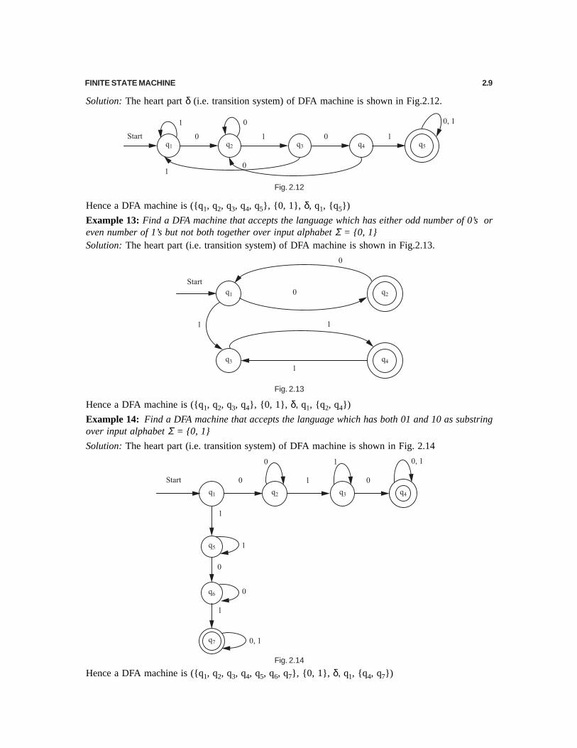
Solution: The transition table of a DFA machine δ is shown below
Fig. 2.22
Hence a DFA machine is ({q1, q2, q3}, {0, 1, 2,}, {4, 5, 6, 7, 8, 9,} δ, q1, {q1})
Example 22: Design a DFA machine that accept the all language ( or strings) which are divisible by3 over the input alphabet ∑ = {0, 1}
Solution: The transition table of a DFA machine δ is shown below
Fig. 2.23
Hence a DFA machine is ({q1, q2, q3}, {0, 1}, δ, q1, {q1})
Example 23: Design a DFA for a vending machine which accepts only 5-rupeecoins and delivers tea for each such coins.
Solution: The heart part (δ) of DFA machine is shown in Fig. 2.24.Hence a DFA machine is ({q0}, {5}, δ, q0, {q0})
Example 24: Design a DFA machine which does not accept any other coins other than rupee 5 overinput alphabet {1, 2, 5}Σ =Solution: The heart part(δ) of DFA machine is shown in Fig. 2.25.
Fig. 2.25
Hence a DFA machine is ({q0, q1}, {1, 2, 5}, δ, q0, {q0})
Fig. 2.24

FINITE STATE MACHINE 2.13
Example 25: Design a DFA nmachine that only accepts any sequence consisting of at least 3 one-rupee coins over input alphabet {1, 2, 5}Σ =Solution: The heart part (δ) of DFA machine is shown in Fig. 2.26.
Fig. 2.26
Hence a DFA machine is ({q0, q1, q2, q3}, {1, 2, 5}, δ, q0, {q3})
Example 26: Design a DFA machine that accepts a sequence of coins in which there is at least onesub-sequence of three consecutive 1’s over input alphabet {1, 2, 5}Σ =Solution: The heart part (δ) of DFA machine is shown in Fig. 2.27.
Fig. 2.27
Hence a DFA machine is ({q0, q1, q2, q3}, {1, 2, 5}, δ, q0, {q3})
Example 27: Design a DFA machine that accepts triple a’s or triple b’s over input alphabet {a, b}Σ =Solution: The heart part (δ) of DFA machine is shown in Fig. 2.28.
Fig. 2.28
Hence a DFA machine is ({q0, q1, q2, q3, q4, q5}, {a, b}, δ, q0, {q5})
Example 28: Design a DFA machine that accept the language b ab bb∈ + + + over input alphabet{a, b}Σ =
2.14 THEORY OF AUTOMATA AND FORMAL LANGUAGES
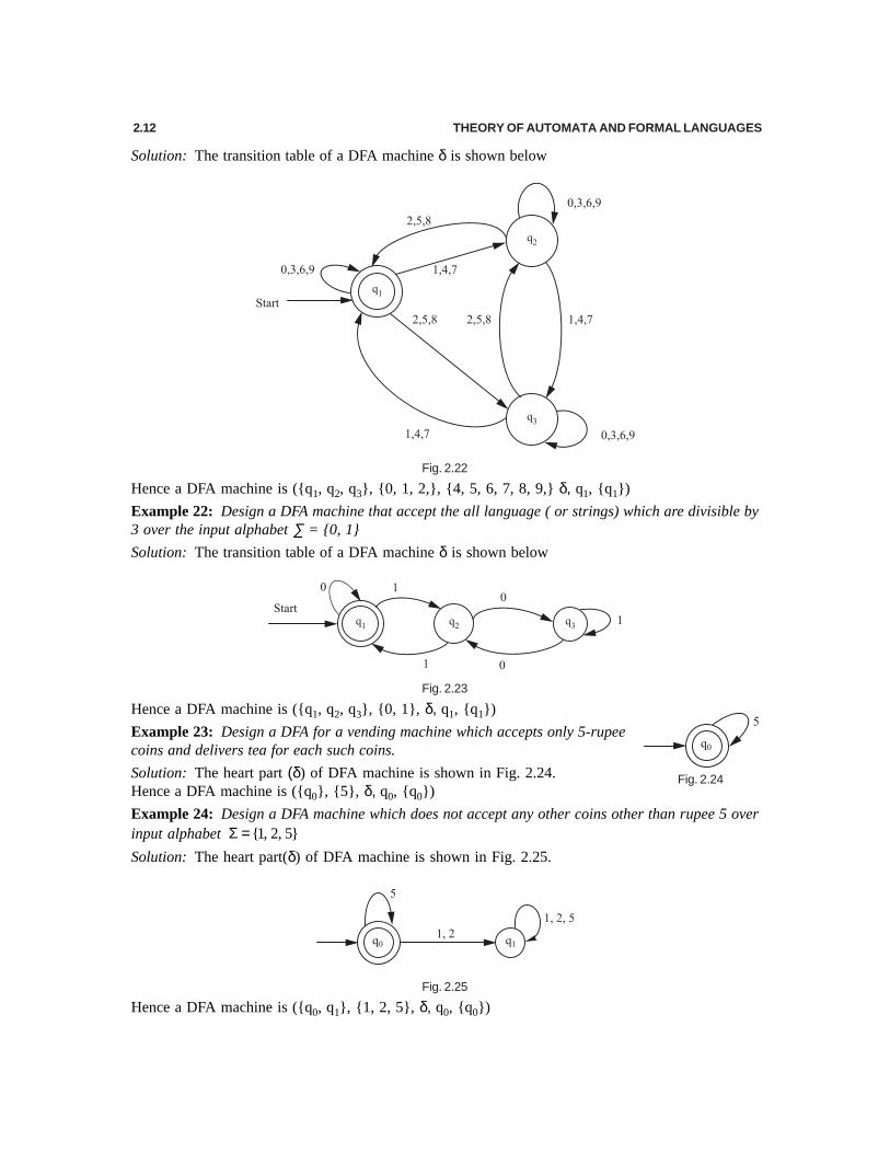
Solution: The heart part (δ) of a DFA machine is shown in Fig. 2.29.
Fig. 2.29
Hence a DFA machine is ({q0, q1, q2, q3, q4, q5}, {a, b}, δ, q0, {q0, q1, q3, q4})
Example 29: Design a DFA machine for the language L = {w ∈ {a, b} : length (w) ≥ 2 and w neitherends in aa nor bb}.
Solution: The heart part (δ) of a DFA machine is shown in Fig. 2.30.
Fig. 2.30
Hence a DFA machine is ({q0, q1, q2, q3, q4}, {a, b}, δ, q0, {q3, q4})
2.3 NON-DETERMINISTIC FINITE AUTOMATA (NFA)
A non-deterministic finite automata (NFA) consists of a variable that can only take on a finite numberof different states, a read head with which the input tape will be read from left to right, a transitionsystem that forms the control of the automaton, an initial state and one or several final states.

FINITE STATE MACHINE 2.15
OR (Mathematically)
A non-deterministic finite automaton (NFA) M consists of 5-tuples.
M = ( Q, ∑, δ, q0, F),
where
Q is a finite non-empty set of states,
∑ is a finite alphabet, the input alphabet,
δ is the transition system which represents a mapping between states with input alphabet to power set of states i.e Q × ∑ → 2Q (2Q is power set of Q)
q0 (q0 ∈ Q) is the initial state and
F (F ⊆ Q) is the set of final states
Note: The only difference between the DFA and NFA is in the transition system δ. For DFA, theoutcome is a state which is an element of Q; for NFA, the outcome is a subset of Q. (it may consist ofone or more elements of Q).
Example 30: Consider the following NFA machine M = ({q0, q1, q2}, {0, 1}, δ, q0, {q1}) where atransition graph is shown in Fig. 2.31.
Fig. 2.31
Check if the string 00001 is accepted by NFA. Also find the sequence of states.
Note: Since the present state q0 contains the next states q0 and q1 on input symbol 0, the transitionsystem is a transition system of NFA and the transition diagram is a NFA.
Solution: The given language is δ(q0, 00001)
= δ(δ(q0, 0), 0001) by rule 2
= δ({q0, q1}, 0001) from transition graph i.e. δ(q0, 0) = {q0, q1}
= δ(δ({q0, q1} 0), 001) by rule 2
= δ((δ(q0, 0) ∪ δ(q1, 0) ), 001)
= δ({{q0, q1}∪ φ},001)
= δ({q0, q1}, 001)
= δ(δ({q0, q1} 0), 01) by rule 2
= δ((δ(q0, 0) ∪ δ(q1, 0) ), 01)
= δ({{q0, q1}∪ φ},01)
= δ({q0, q1}, 01)
= δ(δ({q0, q1} 0), 1) by rule 2
= δ((δ(q0, 0) ∪ δ(q1, 0)), 1)
= δ({{q0, q1}∪ φ}, 1)
= δ({q0, q1}, 1)
= δ(δ({q0, q1} 1), ∈ ) by rule 2

2.16 THEORY OF AUTOMATA AND FORMAL LANGUAGES
= δ((δ(q0, 1) ∪ δ (q1, 1)), ∈ )
= δ({q1 } ∪ { q1, q2} , ∈ )
= δ({{q1, q2},∈ )
= δ({q1, q2}, ∈ )
= δ(q1, ∈ ) ∪ δ(q2, ∈ )
= q1 ∪ q2
= {q1, q2}
This set of states contain the final state q2. Hence the string is accepted by this NFA machine.
The sequence of states corresponding to the input symbol is given by
Example 31: Find the sequence of states corresponding to the input symbol 000011 for the transitiondigraph shown in Fig. 2.31.Solution: The sequence of states of input symbol 000011 corresponding to the given transition digraphis given below
The highest length from starting symbol is 6 and the states are of 6 length from initial state q0 are {q1, q2}.
Since in the states { q1, q2}, q2 is a final state, so the language 000011 is accepted by a NFA machine
Example 32: Design a NFA machine that accept all strings ending with aa over input symbol∑ = {a, b}.
Solution: The transition diagram of NFA machineδ is shown in Fig.2.32.
Hence the NFA machine
M = ({q0,q1,q2}, {a,b},δ, q0, {q2})Fig. 2.32

FINITE STATE MACHINE 2.17
Example 33: Design a NFA machine that accept all strings beginning with ab and ending with bbover input symbol ∑ = {a, b}.
Solution: The transition diagram of NFA machine δ is shown in Fig. 2.33.
Fig. 2.33
Hence NFA machine is ({q0, q1, q2, q3, q4}, {a, b}, δ, q0, {q4})
Example 34: Design a NFA machine that accept all strings with at least two a’s over input symbol∑ = {a, b}.
Solution: The transition diagram of NFA machine δ is shown in Fig. 2.34.
Fig. 2.34
Hence NFA machine is ({q0, q1, q2}, {a, b}, δ, q0, {q2})
Example 35: Design a NFA machine that accept all strings with exactly two b’s and at least one a overinput symbol ∑ = {a, b}.
Solution: The transition diagram of NFA machine δ is shown in Fig. 2.35.
Fig. 2.35
Hence NFA machine is ({q0, q1, q2, q3, q4, q5}, {a, b}, δ, q0, {q3})
2.4 EQUIVALENCE OF NFA AND DFA [U.P.T.U., B.Tech., 2001-2002]For every non-deterministic finite automata (NFA) there exists an equivalent deterministic automata(DFA). The equivalence is defined in terms of language acceptance. Since a NFA is nothing but a finiteautomata in which zero, one or more transition on an input symbol is permitted. We can alwaysconstruct a DFA which will simulate all the moves of NFA on particular input symbol in parallel to geta DFA in which there will be exactly one transition input symbol. Hence it will be a DFA equivalent toNFA.
Since the DFA equivalent to NFA is to simulate the moves of NFA in parallel, every state of DFA willbe a combination of one or more states of NFA. Hence every state of DFA will be represented by somesubset of set of states of NFA and therefore transformation of NFA to DFA is normally called assubset construction. Therefore if subset has n sates then the number of states of DFA will be equivalent
2.18 THEORY OF AUTOMATA AND FORMAL LANGUAGES
to 2n, with initial state corresponding to the subset {q0}. Therefore transformation of NFA to DFAinvolves, finding all possible subsets of set of states of NFA and then considering each subset to bestate of DFA and finding transition from it on every input symbol. But out of all states of DFA obtainedin this way, if any state is not reachable from initial state on any possible input sequence, then such astate does not play any role to decide the language to be accepted by a DFA. Such states are eliminatedfrom the set of states. This can be done as follows
Let M = ( Q, ∑, δ, q0, F ) be a NFA accepting language L. We construct a DFA M′ that can also acceptthe same language L. Then a DFA M′ is defined as follows
M′ = (Q′, ∑, δ′, q0′, F′)where
Q′ = 2Q (Power set of Q or all subset of Q) and all states of Q′ are denoted by[q1, q2, q3 ……, qn ] where q1, q2, q3 ……, qn ∈ Q
Σ = Similar to NFA
q0′ = [q0]
F ′ = Set of all subsets of Q′ containing an element of F( i.e. final state of NFA)
δ′ (Transition system): To define transition system, use the following steps.
Step 1: Draw an initial state (or vertex ) with label [q0 ] of transition diagram δ′Step 2: Take this state ( i.e.[q0]) and identify all next states from Q′ on all different given input
symbols.
Let us consider the next states as [qi, qj, ….., qk] on input symbol 0∈∑ from state [q0]
Create a state labelled [qi, qj, ….., qk] and add to transition digraph δ′ an edge from [q0] to [qi,qj, ….. ,qk] with label 0.
Step 3: Take any state of step 2 (or previously defined state) and find new next state (i.e. it does notexist already) from Q′ on all different given input symbols .
Let us consider the next state as [qi, qj, ….. ,qn] on input symbol 0∈∑ from state[qi, qj, …, qk]
Compute δ′(qi, 0), δ′(qj,0),…... ,δ′(qk,0) and then form a union of all δ′, yielding the set ofstates [qi, qj, ….. ,qn]
Create a state with label [qi, qj, ….. ,qn] and add to transition digraph δ′ an edge from [qi, qj,….. ,qk] to [qi, qj, ….. ,qn] labeled 0.
Step 4: Repeat the step 3 until no new states are generated
Step 5: Draw all states as a final states of δ′ if it contain the final state of NFA.
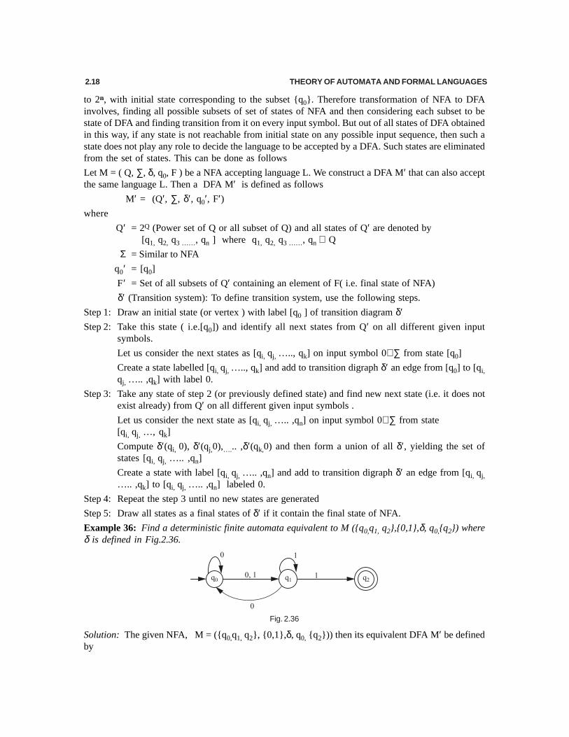
Example 36: Find a deterministic finite automata equivalent to M ({q0,q1, q2},{0,1},δ, q0,{q2}) whereδ is defined in Fig.2.36.
Fig. 2.36
Solution: The given NFA, M = ({q0,q1, q2}, {0,1},δ, q0, {q2})) then its equivalent DFA M′ be definedby

FINITE STATE MACHINE 2.19
M′ = (Q′,∑, δ′,q0′,F′)where
Q′ = 2Q (Power set Q)
i.e.{φ, [q0],[q1],[q2],[q0, q1],[q0,q2],[q1, q2],[q0,q1, q2]}
These are the total number of states of DFA
∑ = Similar to NFA i.e. {0,1}
q0′ = [q0]. This is the initial state of DFA
F ′ = {[q2], [q0,q2],[q1, q2],[q0,q1, q2]}. These are the final states of DFA [ ⊆ Q′ containing q2]
δ′ = The transition digraph is determined as follows:
By step 1: The initial state is [q0], so transition diagram for it is shownhere:
By step 2: The next states from [q0] are [q0,q1] and [q1] on giving inputsymbol 0 and 1 respectively. Then add these new states (i.e. [q0,q1] and[q1]) in transition digraph from state [q0] with labels 0 and 1 respectively.So the new transition digraph is given here
By step 3: The next states from [q1] are [q0] and [q1, q2] on input symbol 0 and 1 respectively, andfrom [q0,q1] are [q0,q1,] and [q1, q2] on giving input symbol 0 and 1 respectively as explained below.
δ′(q1,0) = {q0},
δ′(q1,1) = {q1,q2},
Now, δ′([q0,q1], 0) = δ′(q0,0) ∪ δ′(q1,0) = {q0,q1} ∪ {q0} = {q0,q1}
and, δ′([q0,q1], 1) =δ′(q0,1) ∪ δ′(q1,1) = {q1} ∪ {q1, q2} = {q1,q2}
Since the new state is {q1,q2}.Then add this new state (i.e. [q1,q2] ) in transition digraph from state[q0,q1] with label 1. So the new transition digraph is given below
By step 4: The next state from state [q1,q2] are [q0] and [q1, q2] on input symbol 0 and 1 respectivelyas explained below.
δ′(q1,0) ∪ δ′(q2,0) = [q0] ∪ φ = [q0]
and δ′(q1,1) ∪ δ′(q2,1) = {q1,q2} ∪ φ = {q1,q2}
Hence the transition digraph is given below:
Since no new state is added in this computation so there is no need to do any more computation on anystates

2.20 THEORY OF AUTOMATA AND FORMAL LANGUAGES
By step 5: Draw all states as a final state if it contain the final state of NFA (i.e. q2). Hence the finaltransition diagram is shown in Fig. 2.37.
Fig. 2.37
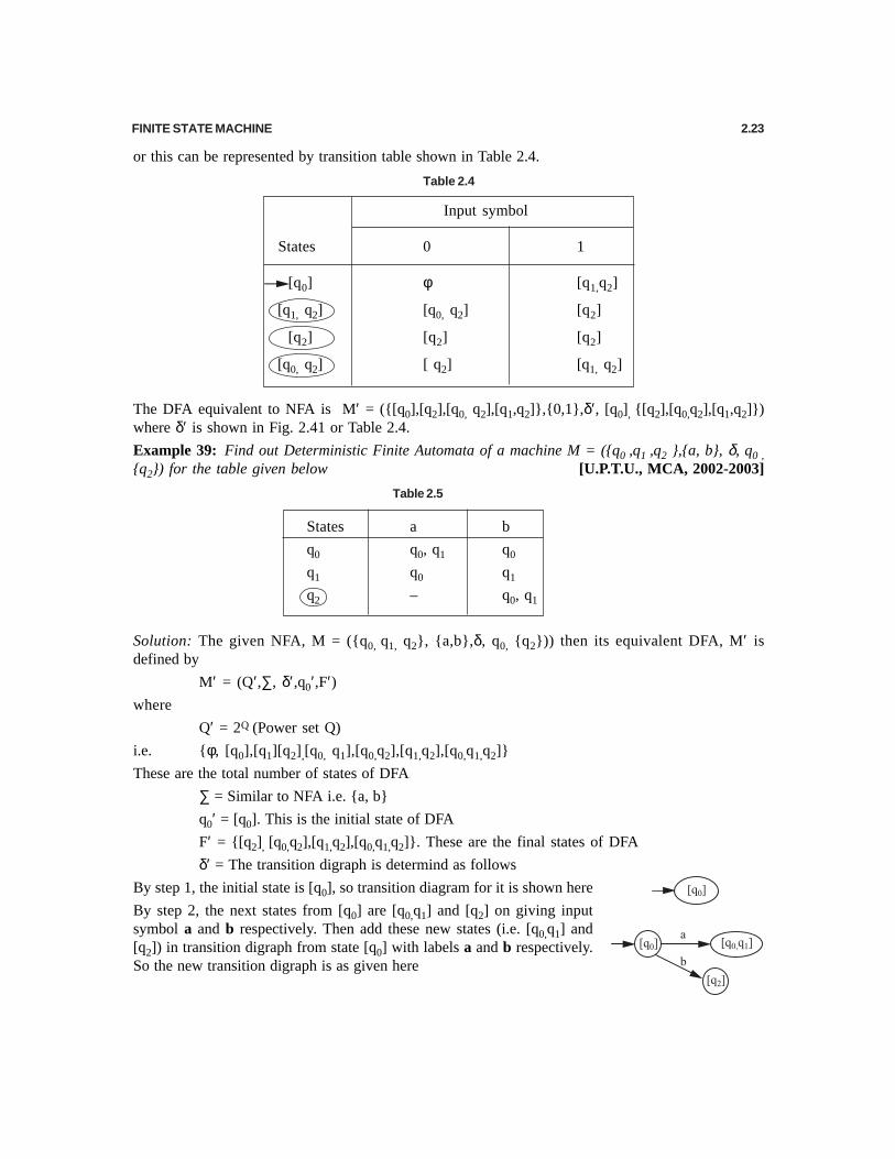
or this can be represented by transition table shown in Table 2.2
Table 2.2
Input symbol
States 0 1
[q0] [q0,q1] [q1]
[q1] [q0] [q1, q2]
[q0,q1] [q0,q1] [q1, q2]
[q1, q2] [q0] [q1,q2]
The DFA equivalent to NFA is M′ = ({[q0],[q1,],[q0,q1], [q1,q2]},{0,1},δ′, [q0], {[q1,q2]}) where δ′ isshown in Fig. 2.37 or Table 2.2.
Example 37: Find a deterministic finite automata equivalent to M=({q0,q1, q2},{0,1},δ, q0,{q1}) whereδ is defined in Fig. 2.38.
Solution: The given NFA M = ({q0,q1, q2}, {0,1},δ,q0, {q1})) then its equivalent DFA M′ is defined by
M′ = (Q′,∑, δ′,q0′,F′)where Q′ = 2Q (Power set Q)
i.e.{φ, [q0],[q1],[q2],[q0, q1],[q0,q2],[q1, q2],[q0,q1, q2]}
These are the total number of states of DFA
∑ = Similar to NFA i.e. {0,1}
q0′ = [q0]. This is the initial state of DFA
F ′ = {[q1], [q0,q1],[q1, q2],[q0,q1, q2]}.These are the final states of DFA
δ′ = The transition digraph is similar to thetransition digraph of Example 29 exceptthe final digraph. Since the final stateis q1, so make all states as a final statewhich contains the state q1. Hence thetransition digraph of DFA is shown inFig. 2.39
Fig. 2.38
Fig. 2.39

FINITE STATE MACHINE 2.21
or this can be represented by transition table shown in Table 2.3
Table 2.3
Input symbol
States 0 1
[q0] [q0,q1] [q1]
[q1] [q0] [q1, q2]
[q0,q1] [q0,q1] [q1, q2]
[q1, q2] [q0] [q1,q2]
The DFA equivalent to NFA is M′ = ({[q0],[q1,],[q0,q1], [q1,q2]},{0,1},δ′, [q0],{ [q1,],[q0,q1], [q1,q2]})where δ′ is shown in Fig. 2.39 or Table 2.3.
Example 38: Find a deterministic finite automata equivalent to M =({q0,q1, q2},{0,1},δ,q0,{q2}) whereδ is defined in Fig. 2.40.
Fig. 2.40
Solution: The given NFA M = ({q0,q1, q2}, {0,1},δ, q0, {q2})), then its equivalent DFA M′ is definedby
M′ = (Q′,∑, δ′,q0′,F′)where
Q′ = 2Q (Power set Q)
i.e. {φ, [q0],[q1][q2],[q0,q1],[q0,q2],[q1,q2],[q0,q1, q2]}
These are the total number of states of DFA
∑ = Similar to NFA i.e. {0,1}
q0′ = [q0]. This is the initial state of DFA
F ′ = {[q2], [q0,q2],[q1, q2],[q0,q1,q2]}. These are the final states of DFA
δ′ = The transition digraph which is determined as follows
By step 1, the initial state is [q0], so transition diagram for it is as shownhere
By step 2, the next states from [q0] are φ and [q1,q2] on giving input symbol0 and 1 respectively. Then add this new state (i.e. [q1, q2] ) in transitiondigraph from state [q0] with label 1. So the new transition digraph is givenhere.

2.22 THEORY OF AUTOMATA AND FORMAL LANGUAGES
By step 3, the next states from [q1, q2] are [q0, q2] and [q2 ] on giving input symbol 0 and 1 respectivelyas explained below.
δ′({q1,q2}, 0) = δ′(q1,0) ∪ δ′(q2,0) = {q0} ∪ {q2} = {q0,q2}
and δ′({q1,q2}, 1) = δ′(q1,1) ∪ δ′(q2,1) = {q2} ∪ {q2} = {q2}
Since the new states are [q0, q2 ] and [q2], we add these new states (i.e. [q0,q2] and [q2] ) in transitiondigraph from state [q1,q2] with labels 0 and 1respectively. The new transition digraph is as shownbelow:
By step 4, the next state from state [q2] are [q2] and [q2] on giving input symbol 0 and 1 and from[q0,q2] are [q2] and [q1,q2] on applying symbol 0 and 1 respectively as explained below.
δ′(q2,0) = {q2},
δ′(q2,1) = {q2},
δ′({q0,q2}, 0) = δ′(q0, 0) ∪ δ′(q2,0) = φ ∪ {q2} = {q2}
and δ′({q0,q2},1) = δ′(q0, 1) ∪ δ′(q2,1) = {q1,q2} ∪ {q2} = {q1,q2}
Since no new state is obtained in this computation so no need to do any more computation on anystates. Hence the transition diagram is shown below:
By step 5, draw all states as a final state if it contains the final state of NFA (i.e. q2). Hence the finaltransition digraph is shown in Fig.2.41.
Fig. 2.41
FINITE STATE MACHINE 2.23
or this can be represented by transition table shown in Table 2.4.
Table 2.4
Input symbol
States 0 1
[q0] φ [q1,q2]
[q1, q2] [q0, q2] [q2]
[q2] [q2] [q2]
[q0, q2] [ q2] [q1, q2]
The DFA equivalent to NFA is M′ = ({[q0],[q2],[q0, q2],[q1,q2]},{0,1},δ′, [q0], {[q2],[q0,q2],[q1,q2]})where δ′ is shown in Fig. 2.41 or Table 2.4.
Example 39: Find out Deterministic Finite Automata of a machine M = ({q0 ,q1 ,q2 },{a, b}, δ, q0 ,{q2}) for the table given below [U.P.T.U., MCA, 2002-2003]
Table 2.5
States a b
q0 q0, q1 q0
q1 q0 q1
q2 – q0, q1
Solution: The given NFA, M = ({q0, q1, q2}, {a,b},δ, q0, {q2})) then its equivalent DFA, M′ isdefined by
M′ = (Q′,∑, δ′,q0′,F′)where
Q′ = 2Q (Power set Q)
i.e. {φ, [q0],[q1][q2],[q0, q1],[q0,q2],[q1,q2],[q0,q1,q2]}
These are the total number of states of DFA
∑ = Similar to NFA i.e. {a, b}
q0′ = [q0]. This is the initial state of DFA
F′ = {[q2], [q0,q2],[q1,q2],[q0,q1,q2]}. These are the final states of DFA
δ′ = The transition digraph is determind as follows
By step 1, the initial state is [q0], so transition diagram for it is shown here
By step 2, the next states from [q0] are [q0,q1] and [q2] on giving inputsymbol a and b respectively. Then add these new states (i.e. [q0,q1] and[q2]) in transition digraph from state [q0] with labels a and b respectively.So the new transition digraph is as given here

2.24 THEORY OF AUTOMATA AND FORMAL LANGUAGES
By step 3, the next states from [q2] are φ and [q0, q1] on given input symbol a and b respectively, andfrom [q0,q1] are [q0,q1,] and [q1, q2] on giving input symbol a and b respectively as explained below.
δ′(q2,a) = {φ},
δ′(q2,b) = {q0,q1},
Now δ′([q0,q1], a) = δ′(q0,a) ∪ δ′(q1,a) = {q0,q1} ∪ {q0} = {q0,q1}
and δ′([q0,q1], b) = δ′(q0,b) ∪ δ′(q1,b) = {q2} ∪ {q1} = {q1,q2}
Since the new state is {q1,q2}.Then add this new state (i.e. [q1,q2] ) in transition digraph from state[q0,q1] with label b. So the new transition digraph is given below
By step 4, the next state from state [q1,q2] are [q0] and [q0, q1] on input symbol a and b respectively asexplained below.
δ′([q1, q2], a) = δ′(q1,a) ∪ δ′(q2,a) = [q0] ∪ φ = [q0]
and δ′([q1, q2], b) = δ′(q1,b) ∪ δ′(q2,b) = {q1} ∪ {q0, q1} = {q0, q1}
Hence the transition digraph is given below
Since no new state is added in this computation so no need to do any more computation on any states.
By step 5 draw all states as final states if these contain the final state of NFA (i.e. q2). Hence the finaltransition diagram is shown in Fig. 2.42.
Fig. 2.42
Hence the DFA equivalent to NFA is M′ = ({[q0],[q1],[q0, q1],[q1,q2]},{a, b},δ′, [q0], {[q1,q2]}) whereδ′ is shown in Fig. 2.42.
FINITE STATE MACHINE 2.25
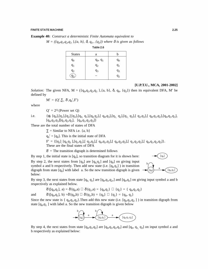
Example 40: Construct a deterministic Finite Automata equivalent to
M = ({q0,q1,q2,q3 },{a, b}, δ, q0 , {q3}) where δ is given as follows
Table 2.6
States a b
q0 q0, q1 q0
q1 q2 q1
q2 q3 q3
q3 – q2
[U.P.T.U., MCA, 2001-2002]
Solution: The given NFA, M = ({q0,q1,q2,q3 },{a, b}, δ, q0, {q3}) then its equivalent DFA, M′ bedefined by
M′ = (Q′,∑, δ′,q0′,F′)where
Q′ = 2Q (Power set Q)
i.e. {φ, [q0],[q1],[q2],[q3],[q0, q1],[q0,q2],[ q0,q3],[q1, q2],[q1, q3],[ q2,q3],[ q0,q1,q2],[q0,q1,q3],[q0,q2,q3][q1,q2,q3], [q0,q1,q2,q3]}
These are the total number of states of DFA
∑ = Similar to NFA i.e. {a, b}
q0′ = [q0]. This is the initial state of DFA
F′ = {[q3], [q0,q3 ],[q1,q3],[ q2,q3],[ q0,q1,q3],[ q0,q2,q3],[ q1,q2,q3],[ q0,q1,q2,q3]}.These are the final states of DFA
δ′ = The transition digraph is determined follows
By step 1, the initial state is [q0], so transition diagram for it is shown here:
By step 2, the next states from [q0] are [q0,q1] and [q0] on giving inputsymbol a and b respectively. Then add new state (i.e. [q0,q1] ) in transitiondigraph from state [q0] with label a. So the new transition digraph is givenbelow:
By step 3, the next states from state [q0, q1] are [q0,q1,q2,] and [q0,q1] on giving input symbol a and brespectively as explained below.
δ′([q0,q1], a) = δ′(q0,a) ∪ δ′(q1,a) = {q0,q1} ∪ {q2} = { q0,q1,q2}
and δ′([q0,q1], b) =δ′(q0,b) ∪ δ′(q1,b) = {q0} ∪ {q1} = {q0, q1}
Since the new state is { q0,q1,q2}.Then add this new state (i.e. [q0,q1,q2 ] ) in transition digraph fromstate [q0,q1 ] with label a. So the new transition digraph is given below
By step 4, the next states from state [q0,q1,q2] are [q0,q1,q2,q3] and [q0, q1, q3] on input symbol a andb respectively as explained below:

2.26 THEORY OF AUTOMATA AND FORMAL LANGUAGES
δ′([q0,q1,q2], a) = δ′(q0,a) ∪ δ′(q1,a) ∪ δ′(q2,a ) = [q0,q1] ∪ [q2] ∪ [q3] = [q0,q1,q2,q3]
and δ′([q0,q1,q2], b) = δ′(q0,b) ∪ δ′(q1,b) ∪ δ′(q2,b ) = [q0] ∪ [q1] ∪ [q3] = [q0,q1,q3]
Hence the transition digraph is given below:
Again applying step 4 the next states from state [q0,q1,q3] are [q0,q1,q2] and [q0, q1, q2] on inputsymbol a and b respectively and from state [q0,q1,q2,q3] are [q0,q1,q2,q3] and [q0,q1,q2,q3] as explainedbelow.
δ′([q0,q1,q3], a) = δ′(q0,a) ∪ δ′(q1,a) ∪ δ′(q3,a ) = [q0,q1] ∪ [q2] ∪ φ = [q0,q1,q2]
δ′([q0,q1,q3], b) = δ′(q0,b) ∪ δ′(q1,b) ∪ δ′(q3,b ) = [q0] ∪ [q1] ∪ [q2] = [q0,q1,q2]
δ′([q0,q1,q2,q3], a) = δ′(q0,a) ∪ δ′(q1,a) ∪ δ′(q2,a )∪ δ′(q3,a )= [q0,q1] ∪ [q2] ∪ [q3]∪ φ = [q0,q1,q2,q3]
δ′([q0,q1,q2,q3], b) = δ′(q0,b) ∪ δ′(q1,b) ∪ δ′(q2,b ) ∪ δ′(q2,b )
= [q0] ∪ [q1] ∪ [q3]∪ [ q2] = [q0,q1,q2,q3]
Hence the transition digraph is given below:
Since no new state is added in this computation so no need to do any more computation on any states
By step 5 draw all states as a final state if it contain the final state of NFA (i.e. q3). Hence the finaltransition diagram is shown in Fig. 2.43.
Fig. 2.43
FINITE STATE MACHINE 2.27
Hence the DFA equivalent to NFA is M′ = ({[q0],[q0, q1],[q0,q1,q2,],[q0,q1,q3], [q0,q1,q2,q3]},{a, b},δ′,[q0], {[q0,q1,q3], [q0,q1,q2,q3]}) where δ′ is shown in Fig. 2.43.
2.5 NFA WITH ∈∈∈∈∈ -MOVES
If a nondeterministic finite automata (i.e. zero, one or more transitions) is modified to allow transitionswith at least one edge without input symbols( i.e. ∈ ), then we get a NFA with ∈ -move, because thetransition without input symbol is called as ∈ -transition.
Or mathematically a non-deterministic finite automaton (NFA) M with ∈ - moves is defined by
M = ( Q, ∑,δ, q0, F), where
Q is a finite non-empty set of states,
∑ is a finite alphabet, the input alphabet,
δ is the transition system which represents a mapping between states with input alphabet or∈ to power set of states
i.e Q × {∑ ∪ ∈ }→ 2 Q ( 2 Q is power set of Q )
q0 (q0 ∈ Q) is the initial state and
F (F∈ Q) is the set of final states
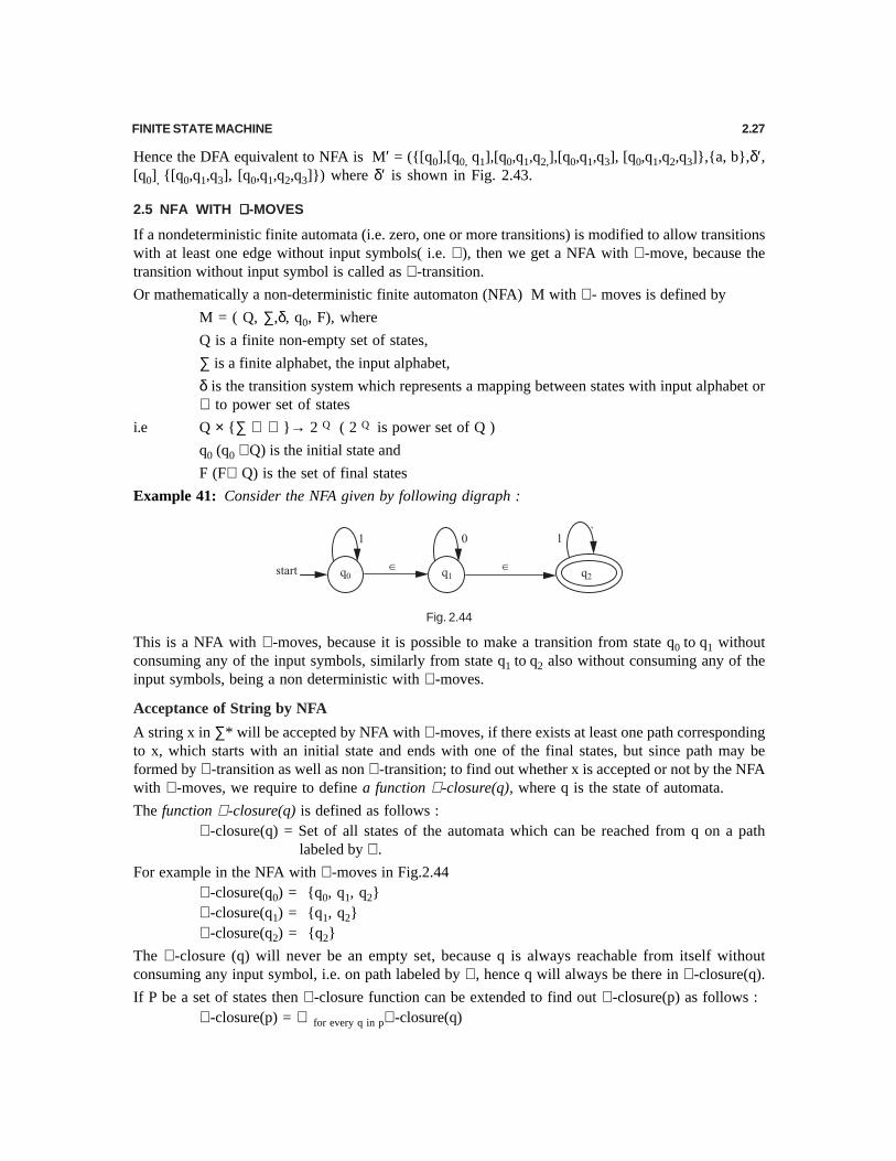
Example 41: Consider the NFA given by following digraph :
Fig. 2.44
This is a NFA with ∈ -moves, because it is possible to make a transition from state q0 to q1 withoutconsuming any of the input symbols, similarly from state q1 to q2 also without consuming any of theinput symbols, being a non deterministic with ∈ -moves.
Acceptance of String by NFA
A string x in ∑* will be accepted by NFA with ∈ -moves, if there exists at least one path correspondingto x, which starts with an initial state and ends with one of the final states, but since path may beformed by ∈ -transition as well as non ∈ -transition; to find out whether x is accepted or not by the NFAwith ∈ -moves, we require to define a function ∈ -closure(q), where q is the state of automata.
The function ∈ -closure(q) is defined as follows :∈ -closure(q) = Set of all states of the automata which can be reached from q on a path
labeled by ∈ .
For example in the NFA with ∈ -moves in Fig.2.44∈ -closure(q0) = {q0, q1, q2}∈ -closure(q1) = {q1, q2}∈ -closure(q2) = {q2}
The ∈ -closure (q) will never be an empty set, because q is always reachable from itself withoutconsuming any input symbol, i.e. on path labeled by ∈ , hence q will always be there in ∈ -closure(q).
If P be a set of states then ∈ -closure function can be extended to find out ∈ -closure(p) as follows :∈ -closure(p) = ∪ for every q in p∈ -closure(q)

2.28 THEORY OF AUTOMATA AND FORMAL LANGUAGES
2.6 EQUIVALENCE OF NFA WITH ∈∈∈∈∈ -MOVES TO NFA WITHOUT ∈∈∈∈∈ -MOVES
For every NFA with ∈ -moves there exists an equivalent NFA without ∈ -moves, accepting the samelanguage. That is we have to find a NFA without ∈ -moves equivalent to a NFA with ∈ -moves or wehave to remove ∈ -transition from a given NFA without changing its behavior, but simply removing the∈ -transitions from a given NFA with ∈ -moves will change the language accepted by an NFA. Hencefor every ∈ -transition, to be eliminated you have to add some non ∈ -transitions as substitute so as keepthe language accepted by the NFA the same. Therefore transformation of NFA with ∈ -moves to NFAwithout ∈ -moves involve finding out the non ∈ -transitions to be added to the NFA for every∈ -transition to be eliminated.
Use the following steps to convert the NFA with ∈ -moves to NFA without ∈ -move.
Let us consider that we want to remove ∈ -moves that changes state q1 to state q2
Step1: Find all the edges starting from state q2
Step 2: Duplicate all these edges starting from state q1 without changing the edge labels.
Step 3: If state q1 is an initial state make state q2 also as initial state.
Step 4: If state q2 is a final state make state q1 also as final state.
Example 42: We want to convert the following NFA with ∈ -moves into NFA without ∈ -moves.
Fig. 2.45
Solution: The ∈ -move is given between state q0 and q1 and q1 and q2 .
So, we first remove ∈ -moves from state q0 to state q1
By step 1: The starting edges from state q1 are 0,1 and ∈By step 2: Duplicate all these edges (i.e. 0,1,∈ ) starting from state q0 without changing the edge
labels.
By step 3: The state q0 is an initial state, make state q1 also as initial state.
By step 4: The state q1 is not a final state, so state q0 shall not be a final state.
The transition digraph looks like as shown in Fig below
Now remove ∈ -moves from state q0 to state q2
By step 1: The starting edge from state q2 is 1
By step 2: Duplicate this edge (i.e. 1 ) starting from state q0 without changing the edge label.
By step 3: The state q0 is an initial state, make state q2 also as initial state.
By step 4: The state q2 is a final state, so state q0 also a final state.
The transition digraph looks like as shown in Fig. 2.46 (a) below
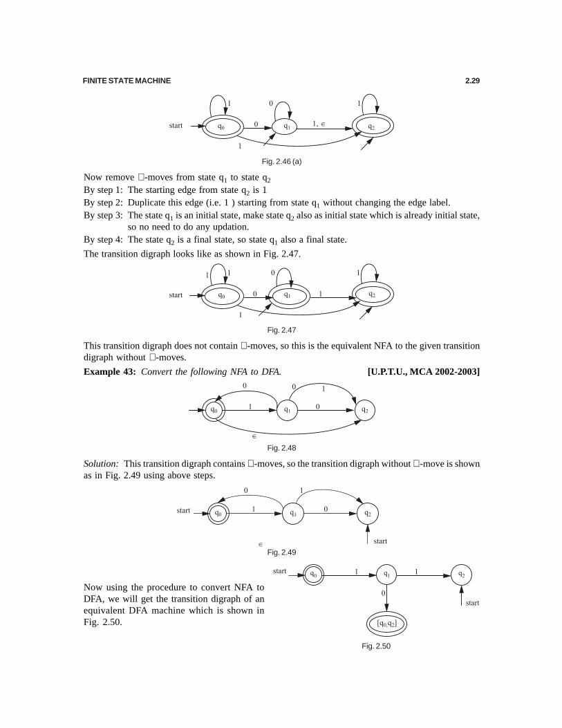
FINITE STATE MACHINE 2.29
Fig. 2.46 (a)
Now remove ∈ -moves from state q1 to state q2
By step 1: The starting edge from state q2 is 1By step 2: Duplicate this edge (i.e. 1 ) starting from state q1 without changing the edge label.By step 3: The state q1 is an initial state, make state q2 also as initial state which is already initial state,
so no need to do any updation.By step 4: The state q2 is a final state, so state q1 also a final state.
The transition digraph looks like as shown in Fig. 2.47.
Fig. 2.47
This transition digraph does not contain ∈ -moves, so this is the equivalent NFA to the given transitiondigraph without ∈ -moves.
Example 43: Convert the following NFA to DFA. [U.P.T.U., MCA 2002-2003]
Fig. 2.48
Solution: This transition digraph contains ∈ -moves, so the transition digraph without ∈ -move is shownas in Fig. 2.49 using above steps.
Fig. 2.49
Now using the procedure to convert NFA toDFA, we will get the transition digraph of anequivalent DFA machine which is shown inFig. 2.50.
Fig. 2.50

2.30 THEORY OF AUTOMATA AND FORMAL LANGUAGES
2.7 MINIMIZATION / OPTIMIZATION OF A DFA
Minimization/optimization of a deterministic finite automata refers to detecting those states of a DFAwhose presence or absence in a DFA does not affect the language accepted by the automata, hencethese states can be eliminated from the automata without affecting the language accepted by theautomata. Such states are Unreachable States, Dead States and Non Distinguishable (or equivalent)States.
Unreachable States
These are those states of a DFA, which are not reachable from the initial state of DFA on any possibleinput sequence.
Dead States
A dead state is that non-final state of a DFA, whose transitions on every input symbol terminates onitself i.e. q is a dead state if q is non final state and δ(q, a) = q for every a in Σ.
Equivalent or Non-distinguishable States
These are those states of DFA for which there exist no distinguishing string. Hence they can not bedistinguished from one another and we can replace all of them by one equivalent state.
We can find equivalent states by the following definitions.
Definition 1: Two states q1 and q2 are equivalent if the transition system of both states on same inputsymbols ( i.e. δ(q1, a) and δ(q2, a)) are exactly equal.
Definition 2: Two states q1 and q2 are equivalent if the transition system of both states on similar inputsymbols ( i.e. δ(q1, w) and δ(q2, w)) are both final states or both of them are non-final states for allw ∈ Σ*.
Definition 3: Two states q1 and q2 are n-equivalent (n ≥ 0 ) if the transition system of both states onsimilar input symbols ( i.e. δ(q1, w) and δ(q2, w)) are final states or both of them are non-final statesfor all string w of length n or less ∈ Σ*.
0-equivalent : 1. Any two final states are 0-equivalent states.
or 2. Any two non-final states are also 0-equivalent states.
1-equivalent: Two states q1 and q2 are 1-equivalent if the transition system of both states on sameinput symbols (i.e. δ(q1, a) and δ(q2, a)) are exactly equal.
2-equivalent: Two states q1 and q2 are 2-equivalent if the transition system of both states on sameinput symbols (i.e. δ(q1, aa) and δ(q2, aa) or δ(q1, ab) and δ(q2, ab) or δ(q1, ba) and δ(q2, ba)or δ(q1, bb) and δ(q2, bb)) are exactly equal.
2.8 CONSTRUCTION OF MINIMUM AUTOMATON
Use the following steps to construct a minimum automatonStep 1: Construct π0 by definition of 0-equivalent i.e.
π0 = (Q10, Q2
0)where Q1
0 = The set of all final states Q2
0 = The set of all non-final states ( i.e. Q – Q10 )
Step 2: Construct π1 from π0 by definition of 1-equivalent
Step 3: Construct πn+1 from πn by definition of n-equivalentStep 4: Construct πk for k = 1,2 ,3,…… until πk = πk + 1 by definition of 1-equivalent

FINITE STATE MACHINE 2.31
Step 5: Convert all states of step 4 into equivalence classes. The equivalence classes are obtained byreplacing a state q by [q].
Example 44: Construct the minimum state automaton equivalent to the transition diagram given inFig.2.51:
Fig. 2.51
Solution: Transition table is a given below:
Table 2.7
State Σ0 1
q0 q1 q0
q1 q0 q2
q2 q3 q1
q3 q3 q0
q4 q3 q5
q5 q6 q4
q6 q5 q6
q7 q6 q3
Q = {q0, q1, q2, q3, q4, q5, q6, q7}
Q10 = {q3}
Q20 = Q – Q1
0 = {q0, q1, q2, q4, q5, q6, q7}
π0 = {{q3}, {q0, q1, q2, q4, q5, q6, q7}}
Formation of πππππ1 is achieved by partitioning the subsets of πππππ0.
Q10 = {q3} can not be partitioned further. So Q1
1 = {q3}
Q20 = {q0, q1, q2, q4, q5, q6, q7} may be partitioned further which can be verified as given
below:
[A] Consider q0 with every other state coming after (succeeding) it i.e. q1, q2, q4, q5, q6, q7 successively as follows.

2.32 THEORY OF AUTOMATA AND FORMAL LANGUAGES
q0 and q1: Entries corresponding to q0 and q1 under 0-col. are q1 ∈ Q20 and q0 ∈ Q2
0 i.e. sameequivalence class Q2
0.
Entries corresponding to q0 and q1 under 1-col. are q0 ∈ Q20 and q2 ∈ Q2
0 i.e. same equivalence class.So q0 is 1-equivalent to q1.
q0 and q2: Entries corresponding to q0 and q2 under 0-col. are q1 ∈ Q20 and q3 ∈ Q1
0 i.e. differentequivalence classes Q1
0 and Q20. Now there is no need to see q0 and q2 in 1-column.
q0 and q4: Entries corresponding to q0 and q4 under 0-col are q1 ∈ Q20 and q3 ∈ Q1
0 i.e. differentequivalence classes Q2
0 and Q10. Now there is no need to see q0. and q4 in 1-col.
q0 and q5: Entries corresponding to q0 and q5 under 0-col. are q1 ∈ Q20 and q6 ∈ Q2
0 i.e. sameequivalence class Q2
0.
Entries corresponding to q0 and q5 under 1-col. are q0 ∈ Q20 and q4 ∈ Q2
0 i.e. same equivalence class.So q0 is 1-equivalent to q5.
q0 and q6: Entries corresponding to q0 and q6 under 0-col are q1 ∈ Q20 and q5 ∈ Q2
0 i.e. sameequivalence class Q2
0.
Entries corresponding to q0 and q6 under 1-col. are q0 ∈ Q20 and q6 ∈ Q2
0 i.e. same equivalence classesQ2
0. So q0 is 1-equivalence to q6.
q0 and q7: Entries corresponding to q0 and q7 under 0-col. are q1 ∈ Q20 and q6 ∈ Q2
0 i.e. sameequivalence class Q2
0.
Entries corresponding to q0 and q7 under 1-col. are q0 ∈ Q20 and q3 ∈ Q1
0 i.e. different equivalenceclasses. So q0 is not 1-equivalent to q7.
Thus q0 is 1-equivalent to q1, q5 and q6.
So Q21 = {q0, q1, q5, q6} Remaining elements are {q2, q4, q7}
[B] Consider q2 with q4, and q7 as q1, q5 and q6 have been included in Q21.
q2 and q4: Entries corresponding to q2 and q4 under 0-col are q3 ∈ Q10 and q3 ∈ Q1
0 i.e. same equivalenceclass Q1
0.
Entries corresponding to q2 and q4 under 1-col are q1 ∈ Q20 and q5 ∈ Q2
0 i.e. same equivalence class.So q2 is 1-equivalent to q4.
q2 and q7: Entries corresponding to q2 and q7 under 0-col are q3 ∈ Q10 and q6 ∈ Q2
0 different equivalenceclasses.
No need to consider – 1-col now.
So q2 is not 1-equivalent to q7.
Therefore Q31 = {q2, q4}. The only element left over is q7. So Q4
1= {q7}
Hence π1 = {{q3}, {q0, q1, q5, q6}, {q2, q4}, {q7}}
Q11 Q2
1 Q31 Q4
1
To find πππππ2:
Formation of πππππ2 is achieved by partitioning the subsets of πππππ11111.
Q12 = {q3} as q3 can not be partitioned further. We shall partition other subsets.
Partitioning of {q0, q1, q5, q6} = Q
[A] Consider q0 with q1, q5 and q6
q0 and q1: Entries corresponding to q0 and q1 under 0-col are q1 ∈ Q21 and q0 ∈ Q2
1 i.e. same class.

FINITE STATE MACHINE 2.33
Entries corresponding to q0 and q1 under 1-col are q0 ∈ Q21 and q2 ∈ Q3
1 different equivalence classes.So q0 is not 2-equivalent to q1.
q0 and q5: Entries corresponding to q0 and q5 under 0-col are q1 ∈ Q21 and q6 ∈ Q2
1 i.e. same class.
Entries corresponding to q0 and q5 under 1-col are q0 ∈ Q21 and q4 ∈ Q3
1 different classes. So q0 is notequivalent to q5.
q0 and q6: Entries corresponding to q0 and q6 under 0-col are q1 ∈ Q21 and q5 ∈ Q2
1 same class.
Entries corresponding to q0 and q6 under 1-col are q0 ∈ Q21 and q6 ∈ Q2
1 same class. So q0 is2-equivalent to q6.
Q22 = {q0, q6}
Left over elements are q1 and q5. So we see if they are 2-equivalent or not. We can see that q1 is2-equivalent to q5. So Q3
2 = {q1, q5}
Again q2 and q4 remain out of which q2 is 2-equivalent with q4.
So, Q42 = {q1, q4}
Q52 = {q7}
So, π2 = {{q3}, {q0, q6}, {q1, q5}, {q2, q4}, {q7}}
To find πππππ3: q0 is 3-equivalent to q6 Q23 = {q0, q6}
Q13 = {q3} q1 is 3-equivalent to q5 Q3
3 = {q1, q5}
q2 is 3-equivalent to q4 Q43 = {q2, q4}
Q53 = {q7}
So π3 is same as π2.
So π2 gives the equivalence classes.
Minimum state automaton is M′ = (Q′, {0, 1}, δ′, q′0, F′)
where Q′ = {{q3}, {q0, q6}, {q1, q5}, {q2, q4}, {q7}}
q′0 = {q0, q6}, F′ = {q3} and δ′ is given below:
Table 2.8
State Σ0 1
[q0, q6] [q1, q5] [q0, q6]
[q1, q5] [q0, q6] [q2, q4]
[q2, q4] [q3] [q1, q5]
[q3] [q3] [q0, q6]
[q7] [q0, q6] [q3]
Note: In fourth row of 1-column, we can not write [q0] as this is no more a state now. It is [q0, q6].Similarly we cannot write [q6] in fifth row of 0-column.
This represents a transition function of a transition system. This can also be represented in the form oftransition digraph, which is shown in Fig. 2.52.
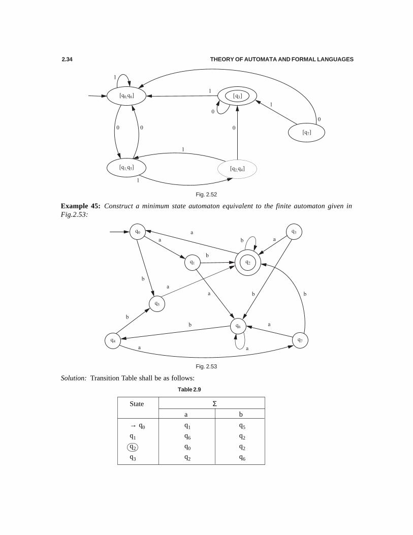
2.34 THEORY OF AUTOMATA AND FORMAL LANGUAGES
Fig. 2.52
Example 45: Construct a minimum state automaton equivalent to the finite automaton given inFig.2.53:
Fig. 2.53
Solution: Transition Table shall be as follows:
Table 2.9
State Σa b
→ q0 q1 q5
q1 q6 q2
q2 q0 q2
q3 q2 q6

FINITE STATE MACHINE 2.35
q4 q7 q5
q5 q2 q6
q6 q6 q4
q7 q6 q2
Q = {q0, q1, q2, q3, q4, q5, q6, q7}
Q10 = {q2}, Q2
0 = Q – Q10 = {q0, q1, q3, q4, q5, q6, q7}
π0 = {{q2}, {q0, q1, q3, q4, q5, q6, q7}}
Determination of π1, by further partitioning of subsets of π0.
Set {q2}cannot be partitioned further so Q11 = {q2} is a subset in π1
Partitioning of Q20 = {q0, q1, q3, q4, q5, q6, q7} to find π1.
A – Consider q0 with every other qi, i = 1, 3, 4, 5, 6, 7 succeeding it separately
(i) q0 and q1: Entries under a-column corresponding to q0 and q1 are q1 and q6 both of which belongQ0
2.
Entries under b-column corresponding to q0 and q1 are q5 and q2. These both ∉ Q10 and also ∉ Q2
0
05 2
02 1
one of them q Q
and the other q Q
∈
∈
So q0 and q1 are not 1-equivalent [Had they both belonged to either Q10 or Q2
0, then q0 and q1, wouldhave been 1-equivalent.
(ii) q0 and q3: Entries corresponding to q0 and q3 under a-col are 0 0
1 2 2 1q Q and q Q
Different sets
∈ ∈
Entries corresponding to q0 and q3 under b-col are 0 0
5 2 6 2q Q and q Q
Same set
∈ ∈
(iii) q0 and q4: Entries corresponding to q0 and q4 under a-col are q1 ∈ Q20 and q7 ∈ Q2
0
Entries corresponding to q0 and q4 under b-col are q5 ∈ Q20 and q5 ∈ Q2
0
(iv) q0 and q5:Entries corresponding to q0 and q5 under a-col are 0 0
1 2 2 1q Q and q Q
Different sets
∈ ∈
Entries corresponding to q0 and q5 under b-col are 0 0
5 2 6 2q Q and q Q
Same sets
∈ ∈
(v) q0 and q6: Entries corresponding to q0 and q6 under a-col are q1 ∈ Q20 and q5 ∈ Q2
0
Entries corresponding to q0 and q6 under b-col are q5 ∈ Q20 and q4 ∈ Q2
0
(vi) q0 and q7:Entries corresponding to q0 and q7 under a-col are q1 ∈ 0 0
2 6 2Q and q Q
same sets
∈
Entries corresponding to q0 and q7 under b-col are 5 2 2 1q Q and q Q
Different sets
∈ ∈
same set
same set
2.36 THEORY OF AUTOMATA AND FORMAL LANGUAGES
Therefore Q12 = {q0, q4, q6} is a subset in π1
Remaining elements are {q1, q3, q5, q7}, q0 is not 1-equivalent to q3, q5 and q7.
B Now consider q1 with each of the other qi (i = 3, 5, 7) successding it i.e. q3, q5, q7 as q4 and q6 havebeen taken in Q′2 as in A.
(i) q1 and q3: Entries corresponding to q1 and q3 under a-col are 0 0
6 2 2 1q Q and q Q
Different sets
∈ ∈
Entries corresponding to q1 and q3 under b-col are 0 0
2 1 6 2q Q and q Q
Different sets
∈ ∈
(ii) q1 and q5: Entries corresponding to q1 and q5 under a-col are q6 ∈ Q20 and q2 ∈ Q1
0
Entries corresponding to q1 and q5 under b-col are q2 ∈ Q10 and q6 ∈ Q2
0
(iii) q1 and q7: Entries corresponding to q1 and q7 under a-col are q6 ∈ Q20 and q6 ∈ Q2
0
Entries corresponding to q1 and q7 under b-col are q2 ∈ Q10 and q2 ∈ Q1
0
So q1 is 1-equivalent to q7. Therefore Q′3 = {q1, q7} is also a subset in π1. Now only q3 and q5 are leftto be considered in Q2
0.
[C] Consider q3 with q5 the only left over value
q3 and q5: Entries corresponding to q3 and q5 under a-col are q2 ∈ Q10 and q2 ∈ Q1
0
Entries corresponding to q3 and q5 under b-col are q6 ∈ Q20 and q6 ∈ Q2
0
So q3 is 1-equivalent to q5
Therefore, Q′′′′′4 = {q3, q5}
Hence π1 = {{q2}, {q0, q4, q6}, {q1, q7}, {q3, q5}}
Now we have to find πππππ2 by further partitionining subsets of πππππ1.
Q12 = {q2} is in π2 as it can not be partitioned further
[D] Consider q0 with q4 and q6
(i) q0 and q4: Entries Corresponding q0 and q4 under a-col are q1 and q7 lying in same equivalenceclass in π1.
Entries Corresponding q0 and q4 under b-col are q5 and q5 lying in same equivalenceclass in π1.
So, q0 and q4 are 2-equivalent.
Therefore {q0, q4} is a subset of π2 or Q22 = {q0, q4}
(ii) q0 and q6:Entries Corresponding q0 and q6 under a-col are q1 and q6 lying in different equivalenceclass in π1.
Entries Corresponding q0 and q6 under b-col are q5 and q4 also lying in different equivalenceclass in π1.
So q0 and q6 are not 2-equivalent.
Therefore {q0, q4, q6} in π1 is partitioned into 2 classes {q0, q4} and {q6} in π2.
q1 and q7 are 2-equivlent i.e. Q32 = {q1, q7}
q3 and q5 are 2-equivlent i.e. Q42 = {q3, q5}
Different sets
same set

FINITE STATE MACHINE 2.37
Hence π2 = {{q2}, {q0, q4}, {q6}, {q1, q7}, {q3, q5}}.
Again q0 and q4 are 2-equivalent
q1 and q7 are 2-equivalent
q3 and q5 are 2-equivalent
Hence π3 = {{q2}, {q0, q4}, {q6}, {q1, q7}, {q3, q5}}
Then π2 = π3
π2 gives the equivalence classes and the minimum state automaton is
M′ = {Q′, {a, b}, δ′, q′0, F′)where Q′ = {[q2], [q0, q4], [q6], [q1, q7], [q3, q5]}
q′0 = [q0, q4] as q0 the initial state has been combined will q4.
F′ = [q2] and δ′ is given below.
Table 2.10
State Σa b
→ [q0, q4] [q1, q7] [q3, q5]
[q1, q7] [q6] [q2]
[q2] [q0, q4] [q2]
[q3, q5] [q2] [q6]
[q6] [q6] [q0, q4]
Note: We can not write [q5] in first row of b-column because it does not remain a state now. Now thestate is [q3, q5] which is written there. Similarly we cannot write [q0] in third row of a-column and [q4]in fifth row of b-column in place of [q0, q4] and [q0, q4] respectively.
Although corresponding to q6 under b-col in original table the state is q4, but q4 is now not a state. Ithas been merged with q0. So the state shall become {q0, q4}
Its transition diagram shown in Fig. 2.54
Fig. 2.54
2.38 THEORY OF AUTOMATA AND FORMAL LANGUAGES
2.9 EQUIVALENCE OF THE FINITE AUTOMATA
Definition
Two finite automata over Σ are equivalent if they accept the same strings over Σ. If they are notequivalent, then there must be some string w over Σ, such that one automaton reaches a final state onapplication of w (i.e. recognizes or accepts w), while the other automaton reaches a non final state onapplication of w (i.e. does not recognize or accept w).
Comparison Method
To test equivalence of two Deterministic Finite Automata (DFA).
M1 and M2 are two FAs over Σ (represented by diagram or otherwise) each consisting of n inputsymbols say a1, a2, …… an i.e., 1 2 n{a ,a , , a }Σ = ……Construct a comparison table having (n + 1) columns. Second, third, …… columns shall correspondto first, second, …… input paths.
First entry in the first column shall consist of the pair of initial states of M1 and M2 e.g. q10 and
q20 (q0
1 ∈ M1 and q02 ∈ M2, both being initial states).
The first entry in second column (a1 –col) shall consist of a1-paths i.e. that pair of states which arereached on application of input a1 to the initial states q1
0 and q02.
The first entry in third column (a2 –col) shall consist of a2-paths i.e. that pair of states which arereached on application of input a2 to the initial states q1
0 and q02.
This procedure is continued to the last column
Then we check all the pairs of states in this first row under each column by the method given below.
Check: If any of the pair under any column is such that one element of the pair denotes the final stateof M1 (or M2) and the other element of the same pair denotes the non final state of M2 (or M1), theconstruction is terminated and it is concluded that M1 and M2 are not equivalent.
If such a condition is not observed in the first row, we proceed to construct the second row asfollows:
Construction of second The pairs of states in first row under second, third, ……..columns (i.e.and Succeeding rows. input columns) that are different from the first entry in the first column are
entered as succeeding entries under first column.
Corresponding to each such entry under first column, we find a1-paths, a2-paths, ………..as explainedearlier.
If any pair of entries (states) in any row under input column is different from all the entries under firstcolumn upto that row, then this pair is also entered as a succeeding entry under first column.
The check as explained earlier is applied at the end of each row to decide whether to terminate thefurther construction (M1 and M2 being declared not equivalent) or to continue the construction of thetable further.
In the latter case the construction is, continued upto that row in which no pair of states is differentfrom all the pairs of states under first column upto that row and in this case we say that the twoautomata are equivalent.
Example 46: Test the equivalence of the following two deterministic finite automata M1 and M2 overΣ = {a, b}.
}
}Firstrow

FINITE STATE MACHINE 2.39
Fig. 2.55
Solution: Comparison table shall consist of 3 columns in all as number of input symbols is 2. Inputsymbols are a and b. Pair of initial states to be kept as first entry of first row under first column is(q0, q3).
Initial state q0 of M1 changes to q0 on receiving input a
Initial state q3 of M2 changes to q3 on receiving input a
Initial state q0 of M1 changes to q1 on receiving input b and under b-col is (q1, q4)Initial state q3 of M2 changes to q4 on receiving input b
Check: No pair of entry in this row contain one final state of M1 ( or M2) and one non-final state ofM2 (or M1).
So proceed further.
Now in first row the entry different from those under col-1 upto row-1 is (q1, q4)
So the second entry under col-1 becomes (q1, q4) in second row.
To find corresponding entries under a and b cols in second row, we proved as in A above.
State q1 of M1 changes to q2 on receiving input a Hence entry in row-2 corresponding to (q1, q4)
State q4 of M2 changes to q5 on receiving input a under a-col is (q2, q5)
State q1 of M1 changes to q0 on receiving input b under b-col is (q0, q3)State q4 of M2 changes to q3 on receiving input b
Check : It allows to proceed further.
In second row the entry different from all the entries under col-1 upto second row is (q2, q5).
So the third entry under col-1 becomes (q2, q5) in third row.
To find corresponding entries in third row under a-col and b-col. (corresponding to entry(q2, q5) under 1-col) we again proceed as in A above.
A
}Hence entry in first row correspondingto (q0 , q3) under a-col is (q0, q3)}
}}
2.40 THEORY OF AUTOMATA AND FORMAL LANGUAGES
State q2 of M1 changes to q1 on receiving input a
State q5 of M2 changes to q6 on receiving input a
State q2 of M1 changes to q2 on receiving input b
State q5 of M2 changes to q5 on receiving input b
Check : allows us to proceed further.
In the third row, the entry different from all the entries under col-1 upto third row is (q1, q6). So thefourth entry under col-1 becomes (q1,q6) in fourth row.
To find corresponding entries in fourth row (corresponding to entry (q1, q6 ) under col-1) weagain proceed as in A.
State q1 of M1 changes to q2 after receiving input a
State q6 of M2 changes to q5 after receiving input a
State q1 of M1 changes to q0 after receiving input b
State q6 of M2 changes to q3 after receiving input b
Check : It allows to proceed further
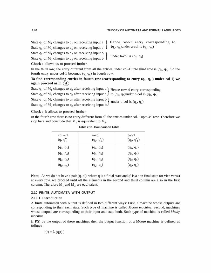
In the fourth row there is no entry different form all the entries under col-1 upto 4th row. Therefore westop here and conclude that M1 is equivalent to M2.
Table 2.11 Comparison Table
col – 1 a-col b-col(q, q′) (qa, q′a) (qb, q′b)
(q0, q3) (q0, q3) (q1, q4)
(q1, q4) (q2, q5) (q0, q3)
(q2, q5) (q1, q6) (q2, q5)
(q1, q6) (q2, q5) (q0, q3)
Note: As we do not have a pair (q, q′), where q is a finial state and q′ is a non final state (or vice versa)at every row, we proceed until all the elements in the second and third column are also in the firstcolumn. Therefore M1 and M2 are equivalent.
2.10 FINITE AUTOMATA WITH OUTPUT
2.10.1 IntroductionA finite automaton with output is defined in two different ways: First, a machine whose outputs arecorresponding to their each state. Such type of machine is called Moore machine. Second, machineswhose outputs are corresponding to their input and state both. Such type of machine is called Mealymachine.
If P(t) be the output of these machines then the output function of a Moore machine is defined asfollows
P(t) = λ (q(t) )
}}
Hence row-4 entry correspondingto (q1, q6)under a-col is (q2, q5)
under b-col is (q0, q3)
} Hence row-3 entry corresponding to (q2, q5)under a-col is (q1, q6)
} under b-col is (q2, q5)

FINITE STATE MACHINE 2.41
The output function of a Mealy machine is defined as follows
P(t) = λ (q(t) . w(t) )
where q(t) is a present state, w(t) is a present input symbol and λ is an output function.
These two machines can be defined mathematically as follows.
2.10.2 Moore Machine
A Moore machine M consists of 6 tuples.M = (Q, Σ, ∆ , δ, λ, q0) where
1. Q is a finite non-empty set of states.
2. Σ is an non-empty set of input symbols
3. ∆ is an output alphabet
4. δ is an transition system and δ ∈ Q × Σ → Q
5. λ is an output function and λ ∈ Q → ∆
6. q0 is a initial state and q0 ∈ Q.
Graphical representation of a Moore Machine is given below.
Fig. 2.56
Here the outputs are a and b corresponding to the non-final and final states respectively.
Tabular representation of the same Moore Machine is given below:
Table 2.12
δ Σ
Input alphabet Outputs
States(Q) 0 l λ
q0 q1 q0 a
q1 q1 q2 a
q2 q2 q2 b
Note: If the length of input string is n then the length of output string is n + 1.
2.10.3 Mealy Machine
A Mealy machine M consists of 6 tuples.
M = (Q, Σ, ∆, δ, λ, q0 ) where
1. Q is a finite non-empty set of states.

2.42 THEORY OF AUTOMATA AND FORMAL LANGUAGES
2. Σ is a non-empty set of input symbols
3. ∆ is an output alphabet
4. δ is a transition system and λ ∈ Q × Σ → Q
5. λ is an output function and λ ∈ Q × Σ → ∆6. q0 is a initial state and q0 ∈ Q.
Graphical representation of a Mealy Machine is given below:
Fig. 2.57
Here the outputs are a and b corresponding to the non-final and final states respectively.
Tabular representation of the same Mealy Machine is as follows:
Table 2.13
δ Σ
Input alphabet Outputs Input alphabet Outputs
States (Q) 0 (λ) l (λ)
q0 q1 a q0 a
q1 q1 a q2 a
q2 q2 b q2 b
Note : If the length of input string is n then the length of output string is also n.
Example 47: Design a Mealy machine to produce a 1’s complement of any binary string.
Solutioin: The transition digraph for a Mealy machine is shown below:
Fig. 2.58
2.10.4 Equivalence of Moore machine and Mealy machine
These two machines are equivalent to each other if they are producing the same output for any giveninput string. Even though if they are not equal, then we can generate equivalent Moore machine fromMealy machine or vice versa.
2.10.4.1 Conversion from Moore machine to Mealy machine
Theorem: If M0 = (Q, Σ, ∆, δ, λ, q0) is a Moore machine then there exists an equivalent Mealymachine Me.
Proof: Let M0 = (Q, Σ, ∆, δ, λ, q0) be a Moore machine then we can define its equivalent Mealymachine Me = (Q′, Σ′, ∆′, δ′, λ′ , q0′) where
Q′ = Q,
FINITE STATE MACHINE 2.43
Σ′ = Σ,
∆′ = ∆,
q0′ = q0
and δ′ and λ′ , are defined as follows
Let us consider a transition system of a Moore machine in the form given inFig. (a).
This Moore machine contains some incoming and outgoing edges on stateq with the output t.
Then the a transition system of a Mealy machine equivalent to this Mooremachine is as given in Fig. (b).
It is obtained by assigning output of a state q to all incoming edges on stateq, which is equivalent to a Mealy machine.
Repeat this procedure of all states of Moore machine and the resultant machine is called a Mealymachine.
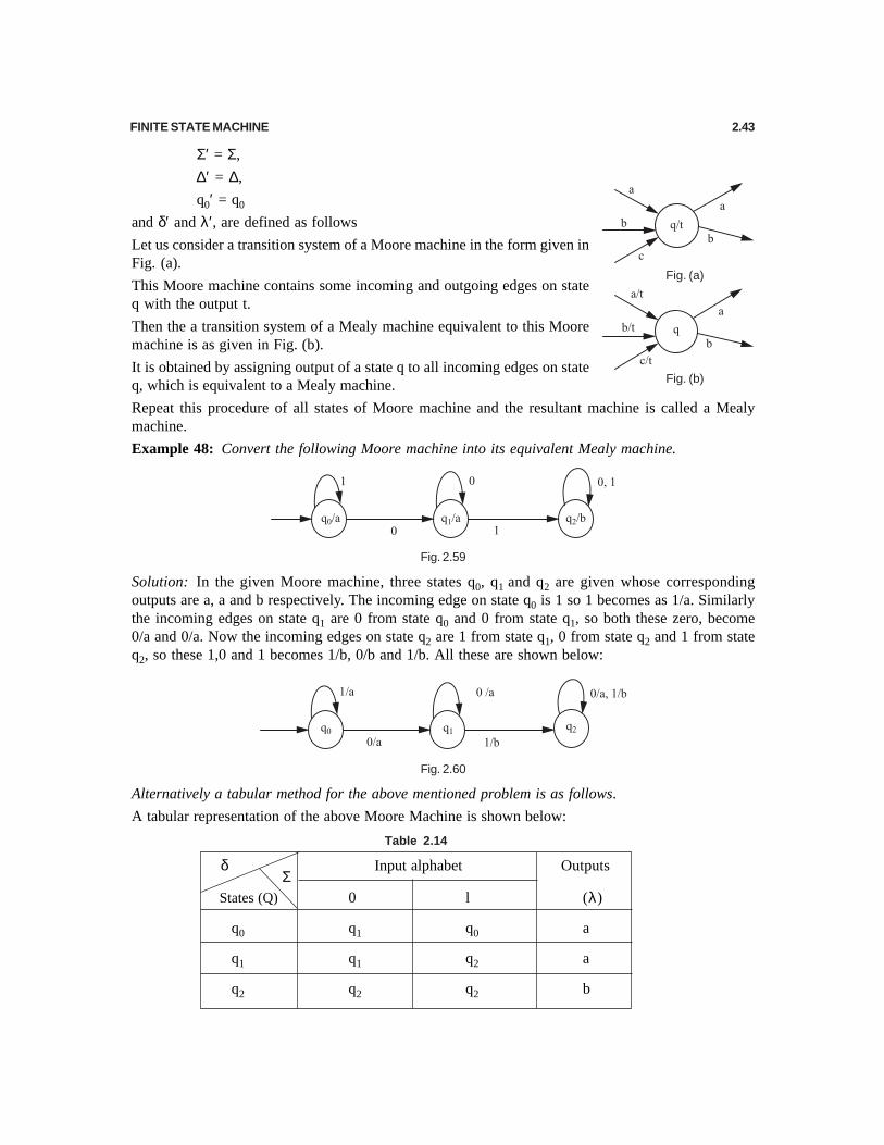
Example 48: Convert the following Moore machine into its equivalent Mealy machine.
Fig. 2.59
Solution: In the given Moore machine, three states q0, q1 and q2 are given whose correspondingoutputs are a, a and b respectively. The incoming edge on state q0 is 1 so 1 becomes as 1/a. Similarlythe incoming edges on state q1 are 0 from state q0 and 0 from state q1, so both these zero, become0/a and 0/a. Now the incoming edges on state q2 are 1 from state q1, 0 from state q2 and 1 from stateq2, so these 1,0 and 1 becomes 1/b, 0/b and 1/b. All these are shown below:
Fig. 2.60
Alternatively a tabular method for the above mentioned problem is as follows.
A tabular representation of the above Moore Machine is shown below:
Table 2.14
δ Σ
Input alphabet Outputs
States (Q) 0 l (λ)
q0 q1 q0 a
q1 q1 q2 a
q2 q2 q2 b
Fig. (a)
Fig. (b)
2.44 THEORY OF AUTOMATA AND FORMAL LANGUAGES
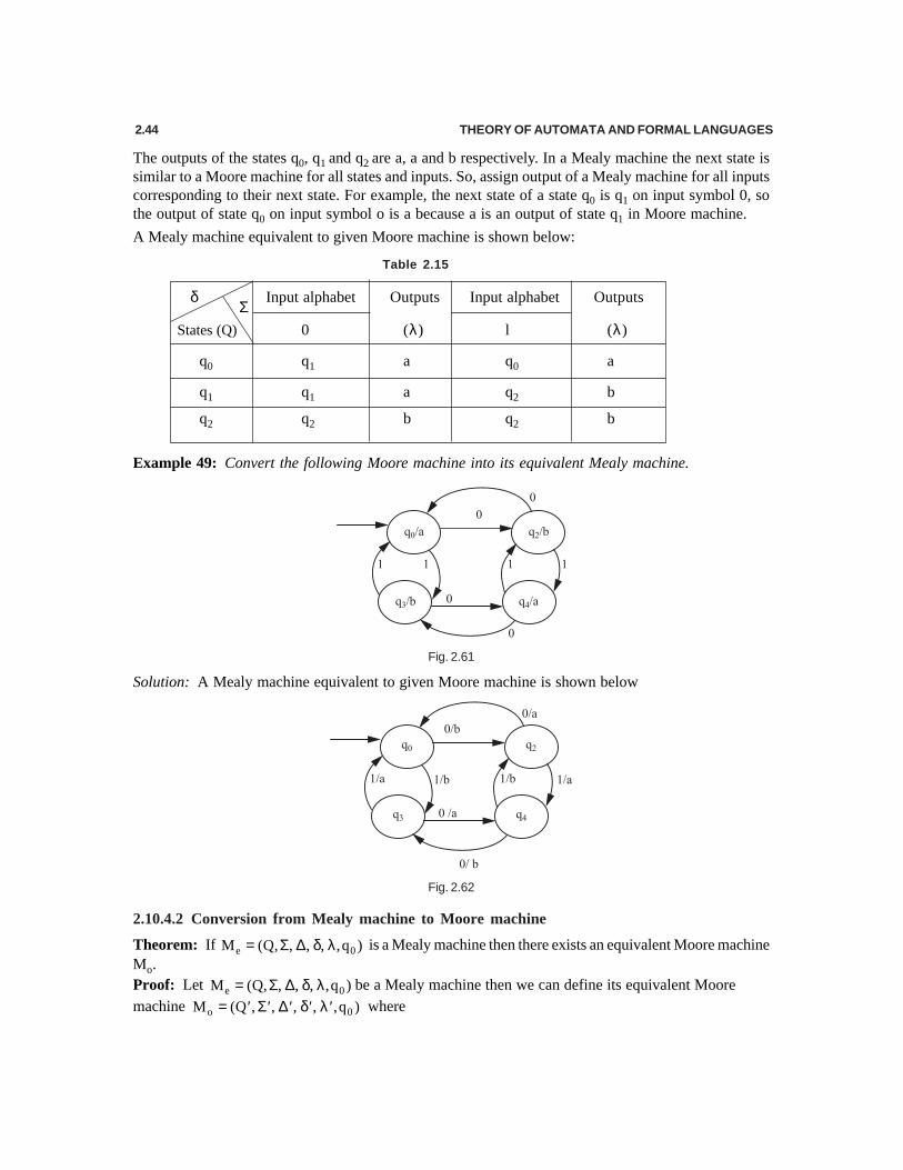
The outputs of the states q0, q1 and q2 are a, a and b respectively. In a Mealy machine the next state issimilar to a Moore machine for all states and inputs. So, assign output of a Mealy machine for all inputscorresponding to their next state. For example, the next state of a state q0 is q1 on input symbol 0, sothe output of state q0 on input symbol o is a because a is an output of state q1 in Moore machine.
A Mealy machine equivalent to given Moore machine is shown below:
Table 2.15
δ Σ
Input alphabet Outputs Input alphabet Outputs
States (Q) 0 (λ) l (λ)
q0 q1 a q0 a
q1 q1 a q2 b
q2 q2 b q2 b
Example 49: Convert the following Moore machine into its equivalent Mealy machine.
Fig. 2.61
Solution: A Mealy machine equivalent to given Moore machine is shown below
Fig. 2.62
2.10.4.2 Conversion from Mealy machine to Moore machine
Theorem: If e 0M (Q, , , , ,q )= Σ ∆ δ λ is a Mealy machine then there exists an equivalent Moore machineMo.Proof: Let e 0M (Q, , , , ,q )= Σ ∆ δ λ be a Mealy machine then we can define its equivalent Mooremachine o 0M (Q , , , , ,q )= Σ ∆ δ λ′ ′ ′ ′ ′ where

FINITE STATE MACHINE 2.45
′Σ = Σ ,
′∆ = ∆ ,
0 0q q′ =
and and′ ′δ λ are defined as follows
If all the incoming edges of a state have same output then assign that output to a particular state. Forexample
If the incoming edges of a state have different outputs then factorize that state corresponding to thedifferent outputs. For example
A Mealy machine with different outputs on their incoming edges to state q is given below:
Then the transition system of a Moore machine equivalent to this Mealy machine is
and Q’ is the total number of states of Moore machine
Repeat this procedure for all incoming edges of all states of Mealy machine. The resultant machine iscalled a Moore machine.
Example 50: Convert the following Mealy machine into its equivalent Moore machine
Fig. 2.63
Solution: In the given Mealy machine, three states q0, q1 and q2 are given. On state q0 there is only oneoutput symbol (= 1) corresponding to the incoming edge Similarly on state q2 there is only one output

2.46 THEORY OF AUTOMATA AND FORMAL LANGUAGES
symbol (= 1) corresponding to the two incoming edges. But on state q1, there are two output symbols(= 0 and 1) corresponding to their two incoming edges. So, we break the state q1 into twoparts corresponding to their outputs according to procedure explained above. Let us consider thesetwo states are q10 and q11 corresponding to the output 0 and 1 respectively. All these are shown inbelow:
Fig. 2.64
Alternatively a tabular method for the above mentioned problem is described below:A tabular representation of the above Mealy Machine is described below.
Table 2.16
δΣ
Input alphabet Outputs Input alphabet Outputs
States (Q) a (λ) b (λ)
q0 q0 1 q1 1
q1 q1 0 q2 1
q2 q2 1 q1 0
A Moore machine equivalent to given Mealy machine is shown below:
Table 2.17
δΣ
Input alphabet Outputs
States (Q) a b λ
q0 q0 q11 1
q10 q10 q2 0
q11 q10 q2 1
q2 q2 q10 1

FINITE STATE MACHINE 2.47
Example 51: Convert the following Mealy machine into its equivalent Moore machine.
Fig. 2.65
Solution: A Moore machine equivalent to given Mealy machine is shown below
Fig. 2.66
Alternatively a tabular method for the above mentioned problem is also given below:
A tabular representation of the above Mealy Machine is shown below:
Table 2.18
δ Σ Input alphabet Outputs Input alphabet Outputs
States (Q) a (λ) b (λ)
q0 q0 a q1 b
q1 q0 0 q1 1
A Moore machine equivalent to given Mealy machine is shown below:
Table 2.19
δ Σ
Input alphabet Outputs
States (Q) a b λ
q0 q0 q1 a
q1 q0 q1 b
2.11 TWO-WAY FINITE AUTOMATA
Two way finite automata is a finite automata in which read/ write head of a transition system will movein both direction ( i.e. left to right or right to left ) but in one direction at a time. It is defined in the formof deterministic and non-deterministic both.
2.11.1 Two-Way Deterministic Finite Automaton (2DFA)
A mathematical model of a 2DFA machine M is given by
0M (Q, , , q ,F)= Σ δ where

2.48 THEORY OF AUTOMATA AND FORMAL LANGUAGES
1. Q is a finite non-empty set of states.
2. ∑ is a finite non-empty set of input symbols
3. δ is a transition system and Q Q {L, R}δ∈ × Σ → ×
4. q0
is an initial state and 0q Q∈
5. F is a set of accepting states (or final states) and F Q⊆
2.11.2 Two-Way Non-Deterministic Finite Automaton (2NDFA) [U.P.T.U., B.Tech., 2002-03]
The difference between 2DFA and 2NDFA lies in definition of transition system s.
A mathematical model of a 2NDFA machine M is given by
M = (Q, Σ, δ, q0, F) where
1. Q is a finite non empty set of states.2. Σ is a finite non empty set of input symbols
3. δ is a transition system and QQ 2 {L, R}δ∈ × Σ → ×4. q
0is an initial state and 0q Q∈
5. F is a set of accepting states (or final states) and F Q⊆
Instantaneous Descriptions (ID) using move relation
An Instantaneous Descriptions( ID ) of Two-way Deterministic Finite Automaton is in the form ofstring xyz, where x is the sub-string of input string , y is the present state of Two-way DeterministicFinite Automaton M and z is also a sub-string of input string and first symbol of z contains the currentsymbol of Read / Write ( R/W) head ,
Example 52: Let us consider a string abcq2defgh over input alphabet Σ = {a, b, c, d, e, f, g h} and
let the present state be q2 and the present symbol under read / write head is d. Then the instantaneous
description of this string is graphically represented as follows:
Moves in a Two-Way Deterministic Finite Automaton
Moves in a Two-way Deterministic Finite Automaton occur under the following two rules:
(i) If the transition function δ (q, ai) = (q1, R) in the input string
1 2 3 i 1 i i 1 i 2 na a a a a a a a− + +… ……
and the present state is q and the present symbol under read / write head is ai. Then the instantaneousdescription before processing ai is
1 2 3 i 1 i i 1 i 2 na a a a q a a a a− + +… ……and after processing ai is
1 2 3 i 1 1 i 1 i 2 na a a a b q a a a− + +… ……
(ii) If the transition function δ (q, ai) = ( q1, L ) in the input stringa1 a2 a3 … a i-1ai a i +1 a i+ 2…… an

FINITE STATE MACHINE 2.49
and the present state is q and the present symbol under read / write head is ai. Then the instantaneousdescription before processing ai is
a1 a2 a3….. a i–1 q ai a i +1 a i+ 2 …….. an
and after processing ai isa1 a2 a3….. a i–2 q1 a i–1 b a i +1 a i + 2 …… an
Acceptability of a language (or string) by a Two-Way Deterministic finite AutomatonA language (string) w is accepted by a two-way finite automaton 0M (Q, , , q , F)= Σ δ if 0(q , w) qδ =for some q ∈ F.
Example 53: Consider the following 2DFA machine M = ({q0 , q1 , q2}, {0, 1}, δ, q0 {q1}) where atransition graph is shown below
Check if the string 010110 is acceptedby 2DFA. Also find the sequence ofstates.
Solution: The Instantaneous Descrip-tions (ID) of a given input and itsmoves are represented asfollows:
q0010110
0q110110
01q10110
0q210110
01q00110
010q1110
0101 q110
01011 q10
0101 q210
01011 q00
010110 q1 ∈q1 ∈∈∈∈∈ F
Hence the string is accepted by 2DFA machine.
The sequence of states corresponding to the input symbol is given by
Such type of sequence of states is called crossing sequence.
⊥⊥
⊥⊥
⊥⊥
⊥⊥
⊥
Fig. 2.67
⊥⊥

2.50 THEORY OF AUTOMATA AND FORMAL LANGUAGES
EXERCISE
A. Choose the most appropriate alternative in each of the following questions.
1. The maximum number of states in a DFA which is equivalent to a NFA having n states are(a) 2n (b) n2 (c) n (d) none of these
2. Two DFA’s M1 and M2 are equivalent if:(a) M1 and M2 have the same final states(b) M1 and M2 have the same number of states(c) M1 and M2 accept the same language i.e. L (M1) = L (M2)(d) none of these
3. If in a finite automata 0M (Q, , , q , F),= Σ δ δ maps Q × Σ to 2Q, then
(a) M is NFA (b) M is DFA(c) M is NFA with ε moves (d) none of these
4. A DFA has(a) only one final state(b) more than one final states(c) unique path to final state for a set of inputs(d) all the above
5. The language generated by a DFA is(a) context free (b) regular (c) context sensitive (d) all the above
6. A DFA can recognize(a) Regular grammar only (b) CFG(c) Any grammar (d) none of these
7. For a DFA, 0M {S, , , q , F),= Σ δ the transition function δ is given by
(a) : Sδ × Σ → Σ (b) : S Sδ × → Σ(c) ( ): S {A} Qδ × Σ ∪ → (d) : S S+δ × Σ →
8. If L is a non-empty language such that | w| = n where w L,∈ then DFA which accepts L shall have
(a) (n + 1) states (b) at least (n + 1) states(c) atmost (n + 1) states (d) n states
9. For a NFA 0M (S, , , q ,F),= Σ δ the transition function δ is given by
(a) S: S 2δ × Σ = (b) : S Sδ × Σ →
(c) S: S ( { }) 2δ × Σ ∪ ∈ → (d) none of these
10. The automate in which output depends on the status of the machine only is(a) Moore machine (b) Mealy machine(c) Any automata (d) both (a) and (b)
11. The automaton in which output depends on states and input is called(a) Moore machine (b) Mealy machine(c) both (a) and (b) (d) none of these
12. Mealy machine is an(a) an automaton in which output depends on input only(b) an automaton in which output depends on state only

FINITE STATE MACHINE 2.51
(c) an automaton in which output depends on input and state both(d) none of these
13. The main difference between Moore and Mealy machine is(a) output of Moore machine depends on present state only(b) output of Moore machine depends on present input only(c) output of Moore machine depends on present state and input(d) none of these
14. Can a DFA simulate NFA(a) yes (b) no (c) sometimes (d) depends on DFA
15. The FA whose transition diagram is given below accepts
(a) all words over (a, b)Σ = including ∈ (b) only ∈
(c) all words over (a, b)Σ = such that a and b alternate
(d) all words over (a, b)Σ = except ∈
B. Fill in the blanks.1. DFA stands for............................... .2. NFA stands for............................... .3. The transition system of a DFA machine is defined by............................... .4. The transition system of a NFA machine is defined by............................... .5. Every NFA machine is also recognized by............................... .6. A dead state is always................................state.7. Two states are equivalent if............................... .8. A machine whose outputs depends upon only states is called ................................ .9. A machine whose outputs depends upon state and input both is called ......................... machine.
10. In Moore machine, if length of input string is n then the length of ouoput string is .......... .11. In Mealy machine, if length of input string is n then the length of output string is..................... .12. 2DFA stands for................................ .13. The transition system of a 2DFA machine is defined by ................................ .14. A final state of each machine is always................................ of states.15. DFA machine always recognizes ............................... language.
C. State whether the following statements are True (T) or False (F).
1. A non-deterministic finite automata is more powerful than a deterministic finite automata.2. Every infinite language is non-regular.3. A DFA equivalent to a given NDFA must have less number of states than the number of states of
the NDFA.4. For a finite automata (q, x w) (q, w x)δ = δ .
5. For a finite automata ( )(q, x w) (q, x), wδ = δ .
6. For a finite automata (q, ) qδ λ = .

2.52 THEORY OF AUTOMATA AND FORMAL LANGUAGES
7. A Mealy machine has no terminal state.
8. A Moore machine generates no language as such.
9. Context sensitive grammer can be recognized by finite state automata.
10. A language is accepted by finite automata if and only if it is right linear.
11. The powers of DFA and NDFA are the same.
12. The languages accepted by finite automata are the languages denoted by regular expressions.
13. For every DFA there is a regular expression denoting the language.
14. Finite machines can not recognize palindromes.
D. Write the answer of the following questions.
1. Which of the following strings are accepted by the DFA machine M whose transition diagram isshown below.
(a) aaab (b) abaab (c) aaaaba (d) ababbaa (e) bbbb(f) bbbabba (g) aaaababb (h) aaaaaa (i) bbbabb
2. For the transiiotn diagram M given in Q.1, find the sequence of states for the following inputs(a) aaaaabaaa (b) baaabb (c) bbbbbb (d) bbaaabb (e) aabbaabb
3. Design a DFA machine M for the following language(a) L ={ ab4wb3 : w ∈ {a, b}*} (b) L = {awa : w ∈ {a, b}*}(c) L = {bw1abw2 : w1, w2 ∈ {a, b}*} (d) L = {w : |w| mod 3 = 0, w ∈ {a, b}*}(e) L = {w : |w| mod 3 ≠ 0, w ∈ {a, b}*} (f) L = {anbm : n ≥ 1, m ≥ 2}(g) L = {anb : n ≥ 0} ∪ {bna: n ≥ 1} (h) L = {an : n ≥ 0, n ≠ 3}
4. Find all set of strings of DFA machine M whose transition diagram is shown in below:
5. Find a language L accepted by the automaton in the figure given below. Also design a DFA thataccepts L2.
6. Design a DFA machine M over {a, b} that accepts the strings in which the left most symbol differfrom right most one.
7. Design a DFA machine over input alphabet ∑ = {a,c,m,r,t } that accepts the strings mat, rat or cat.
8. Design a DFA with exactly six states that accepts the same language as the DFA shown below:
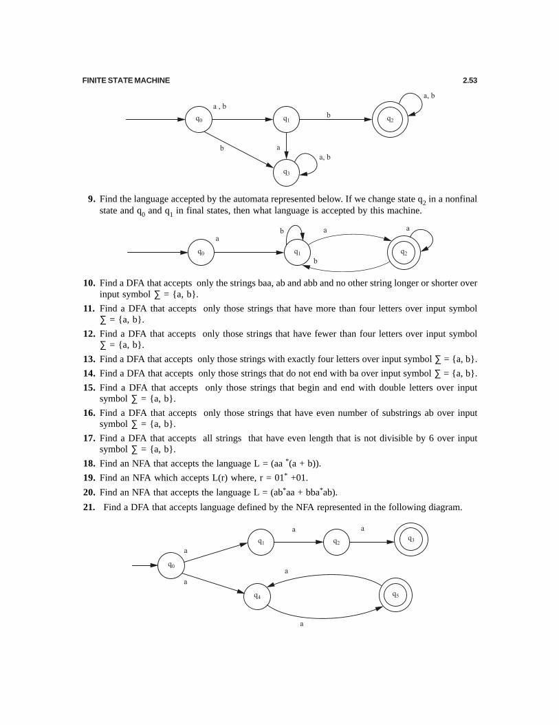
FINITE STATE MACHINE 2.53
9. Find the language accepted by the automata represented below. If we change state q2 in a nonfinalstate and q0 and q1 in final states, then what language is accepted by this machine.
10. Find a DFA that accepts only the strings baa, ab and abb and no other string longer or shorter overinput symbol ∑ = {a, b}.
11. Find a DFA that accepts only those strings that have more than four letters over input symbol∑ = {a, b}.
12. Find a DFA that accepts only those strings that have fewer than four letters over input symbol∑ = {a, b}.
13. Find a DFA that accepts only those strings with exactly four letters over input symbol ∑ = {a, b}.
14. Find a DFA that accepts only those strings that do not end with ba over input symbol ∑ = {a, b}.
15. Find a DFA that accepts only those strings that begin and end with double letters over inputsymbol ∑ = {a, b}.
16. Find a DFA that accepts only those strings that have even number of substrings ab over inputsymbol ∑ = {a, b}.
17. Find a DFA that accepts all strings that have even length that is not divisible by 6 over inputsymbol ∑ = {a, b}.
18. Find an NFA that accepts the language L = (aa *(a + b)).
19. Find an NFA which accepts L(r) where, r = 01* +01.
20. Find an NFA that accepts the language L = (ab*aa + bba*ab).
21. Find a DFA that accepts language defined by the NFA represented in the following diagram.

2.54 THEORY OF AUTOMATA AND FORMAL LANGUAGES
22. What is the complement of the language accepted by the NFA shown below.
23. Let L be the language accepted by the NFA in figure of Q. 22. Find an NFA that accepts L U{a5}.
24. Find an NFA that accepts {a}* and is such that if in its transition graph a single edge is removed(without any other changes), the resulting automaton accepts{a}.
25. Let L be the language accepted by the NFA shown in the figure below. Find an NFA that acceptsL{a5}.
26. Convert the NFA in the figure to a DFA.
27. Convert the NFA into an equivalent DFA.
28. Convert the following NFA into an equivalent DFA.
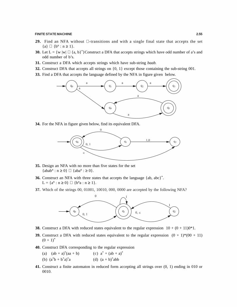
FINITE STATE MACHINE 2.55
29. Find an NFA without ∈ -transitions and with a single final state that accepts the set{a} ∪ {bn : n ≥ 1}.
30. Let L = {w |w| ∈ {a, b}*}Construct a DFA that accepts strings which have odd number of a’s andodd number of b’s.
31. Construct a DFA which accepts strings which have sub-string baab.
32. Construct DFA that accepts all strings on {0, 1} except those containing the sub-string 001.
33. Find a DFA that accepts the language defined by the NFA in figure given below.
34. For the NFA in figure given below, find its equivalent DFA.
35. Design an NFA with no more than five states for the set{ababn : n ≥ 0} ∪ {aban : ≥ 0}.
36. Construct an NFA with three states that accepts the language {ab, abc}*.L = {an : n ≥ 0} ∪ {bna : n ≥ 1}.
37. Which of the strings 00, 01001, 10010, 000, 0000 are accepted by the following NFA?
38. Construct a DFA with reduced states equivalent to the regular expression 10 + (0 + 11)0*1.
39. Construct a DFA with reduced states equivalent to the regular expression (0 + 1)*(00 + 11)(0 + 1)*
40. Construct DFA corresponding to the regular expression
(a) (ab + a)*(aa + b) (c) a* + (ab + a)*
(b) (a*b + b*a)*a (d) (a + b)*abb
41. Construct a finite automaton in reduced form accepting all strings over (0, 1) ending in 010 or0010.

2.56 THEORY OF AUTOMATA AND FORMAL LANGUAGES
42. Find minimal DFA’s for the following languages
(a) L = {anbm : n ≥ 2, m ≥ 1}
(b) L = {anb : n ≥ 0} ∪ {bna : n ≥ 1}
(c) L = {an : n ≥ 0, n ≠ 3}
43. Find the languages accepted by the finite automate with the following transition diagram:
Hint: (a) All the strings of binary digits whose integer value is an integral power of 2.
(b) All the strings of a’s and b’s having every occurrence of b preceded by at least one a.
44. Prove or disprove the following connective. If M = {Q, Σ, δ, q0, F} is a minimal DFA for a regularlanguage L, then M = (Q, Σ, δ, q0, Q F) is a minimal DFA for Σ.
45. Write a computer program that produces a minimal DFA for any given DFA.
46. Show that indistinguishability is an equivalence relation but that distinguishing ability is not.
47. Minimize the number of states in the DFA figure:

FINITE STATE MACHINE 2.57
48. Minimize the states in the DFA depicted in the following diagram:
49. Show that if L is a non empty language such that any w in L has length at least n, then any DFAaccepting L must have at least n + 1 states.
50. Prove the following: if the states qa and qb are indistinguishable, and if qa and qc are distinguishable,then q
b and q
c must be distinguishable.
51. Verify if the following two automata are equivalent or not.
[Hint: Proceeding as in the previous example the comparison table comes out to be as follows:
Comparison Table
col – 1 a-col b-col(q, q′) (qa, q′a) (qb, q′b)
(q0, q3) (q0, q3) (q1, q4)
(q1, q4) (q2, q6) (q0, q5)

2.58 THEORY OF AUTOMATA AND FORMAL LANGUAGES
Now in row-2 we have a pair (q0, q5) such that q0 is final state of M1 and q5 is non-final state of M2.We do not proceed and terminate the construction with the conclusion that M1 and M2 are not equivalent.
52. Construct a minimum automaton equivalent to a given automaton M whose transition table is givenbelow:
State Input symbol Σ0 1
→ q0 q0 q3
q1 q2 q5
q2 q3 q4
q3 q0 q5
q4 q0 q6
q5 q1 q4
q6 q1 q3
53. Draw Non-deterministic finite automata with specified number of states to accept the followinglanguages:
(i) All strings that contain the sub string 0 | 01 (5 states). [U.P.T.U., B.Tech., 2001-02]
Hint. A non-deterministic finite automata M for all strings that contain the sub string 0|01 with5 states is defined as follows
M = (Q, ∑, δ, q0, F)
and transition system δ is shown below
Since the transition system δ contains 5 states, so
Q = { q0 , q1, q2 ,q3,q4}
∑ = {0,1}
q0 = { q0} is a initial states.
F = {q4} is a final states.
Hence the NDFA machines M is
M = ({q0, q1, q2 ,q3,q4},{0,1}, δ,{q0,}, {q4 })54. All strings that the third symbol from the right end is a “0” ( 4 states).
[U.P.T.U., B.Tech., 2001-02]
Hint. The non-deterministic finite automata M for all string such that the third symbol fromthe rightend is a “0” over input alphabets {0,1} is define as follows

FINITE STATE MACHINE 2.59
M = {Q, ∑, δ, q0, F}
and transition system δ is shown below
Since the transition system δ contains four states, so
Q = { q0 , q1, q2 ,q3}
∑ = {0,1}
q0 = { q0}
F = {q3}
Hence the NDFA machines is
M = { { q0 , q1, q2 ,q3},{0,1}, δ,{q0,}, {q3 }}55. What is Moore Machine ? Change the given Moore machine into Mealy machine:
[U.P.T.U., B.Tech., 2002-03]
Hint. See article 2.10.2 on page 2.41 and conversion is similar to example 49 on page 2.4456. Construct a DFA equivalent to the following NDFA: [U.P.T.U., B.Tech., 2002-03]
Hint. Similar to example 36 on page 2.18

2.60 THEORY OF AUTOMATA AND FORMAL LANGUAGES
57. Draw DFA for following over the set
Σ = {0, 1}
(i) L = {w | | w | mod 3 = 0}
(ii) L = {w | | w | mod 3 > 1}
Note | w | represents the length of the string w. [U.P.T.U., B.Tech., 2003-04]
Hint. (i)
(ii)
58. Consider the following generalized transition diagram: [U.P.T.U., B.Tech., 2003-04]
(i) Find an equivalent generalized transition graph with two states.
(ii) What is the language accepted by this machine?
Hint. (i) The transition diagram of two states is
59. Convert the following NFA to equivalent DFA. [U.P.T.U., B.Tech., 2004-05]

FINITE STATE MACHINE 2.61
0 1
P {q,} {q,}
*q {r} {q, r}
R {s} {p}
*s {p}
→
φ
Hint. Similar to example 39 on page 2.23
60. Construct DFA from the graph given below. [U.P.T.U., B.Tech., 2004-05]
Hint. Similar to example 36 on page 2.18
61. Design NFA to recognize the following sets of string abc, abd and aacd. Assume the alphabet is{a,b,c,d}. [U.P.T.U., B.Tech., 2004-05]
Hint. The heart part (i.e. transition system) of NFA machine is shown in below
62. Describe an English language accepted by following FAS. [U.P.T.U., B.Tech., 2004-05]
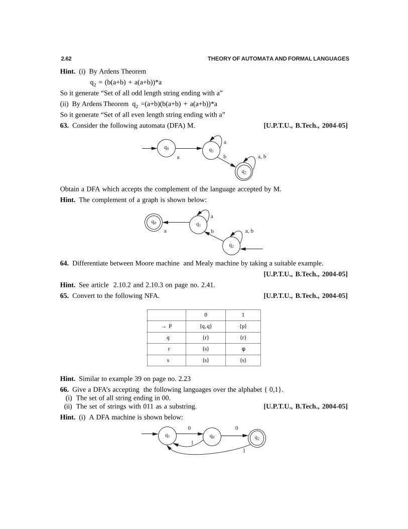
2.62 THEORY OF AUTOMATA AND FORMAL LANGUAGES
Hint. (i) By Ardens Theorem
q2 = (b(a+b) + a(a+b))*a
So it generate “Set of all odd length string ending with a”
(ii) By Ardens Theorem q2 =(a+b)(b(a+b) + a(a+b))*a
So it generate “Set of all even length string ending with a”
63. Consider the following automata (DFA) M. [U.P.T.U., B.Tech., 2004-05]
Obtain a DFA which accepts the complement of the language accepted by M.
Hint. The complement of a graph is shown below:
64. Differentiate between Moore machine and Mealy machine by taking a suitable example.
[U.P.T.U., B.Tech., 2004-05]
Hint. See article 2.10.2 and 2.10.3 on page no. 2.41.
65. Convert to the following NFA. [U.P.T.U., B.Tech., 2004-05]
0 1
P {q,q} {p}
q {r} {r}
r {s}
s {s} {s}
→
φ
Hint. Similar to example 39 on page no. 2.23
66. Give a DFA’s accepting the following languages over the alphabet { 0,1}.(i) The set of all string ending in 00.(ii) The set of strings with 011 as a substring. [U.P.T.U., B.Tech., 2004-05]
Hint. (i) A DFA machine is shown below:

FINITE STATE MACHINE 2.63
(ii) A DFA machine is shown below
67. Design a NFA to recognize the following set of strings. 0101, 101 and 011. Assume the alphabetis {0, 1}. Hence obtain the equivalent deterministic finite automata DFA.
[U.P.T.U., B.Tech., 2004-05]
Hint. The heart part (i.e. transition system) of NFA machine is shown in below:
Convert it into DFA, Similar to example 43 on page 2.2.29
68. Define nondeterministic finite automata. How does it differ from deterministic finite automata?[U.P.T.U., B.Tech., 2007-08]
69. (i) Design a DFA which accept that set of strings over alphabet {1, 2, 3, 4}Σ = such that string
when interpreted as decimal numbers, sum of their digits are divisible by 5.[U.P.T.U., B.Tech., 2007-08]
Hint:
70. Convert following NFA to equivalent DFA and hence minimize the number of states in the DFA. [U.P.T.U., B.Tech., 2007-08]

2.64 THEORY OF AUTOMATA AND FORMAL LANGUAGES
71. (i) Let M1 and M2 be the FA recognizing the languages L1 and L2 respectively.[U.P.T.U., B.Tech., 2007-08]
Draw finite automata which recognize the language L2 – L1.
(ii) Transform the following Mealy machine into equivalent Moore machine.
(A) ANSWERS
1. (a) 2. (c) 3. (a) 4. (c) 5. (b) 6. (a)7. (a) 8. (b) 9. (c) 10. (a) 11. (b) 12. (c)
13. (a) 14. (a) 15. (b)
(B) ANSWERS
1. deterministic finite automaton 2. non-deterministic finite automaton3. Q Q× Σ → 4. QQ 2× Σ →5. DFA machine 6. non-final
7. 1 2(q , w) (q , w)δ ≡ δ 8. moore machine9. mealy machine 10. n + 1
FINITE STATE MACHINE 2.65
11. n 12. two-way deterministic finite automaton13. Q Q (L, R)× Σ → × 14. subset
15. regular
(C) ANSWERS
1. False 2. False 3. False 4. False 5. True 6. True7. True 8. False 9. False 10. True 11. True 12. True
13. True 14. True