Embed Size (px)
Citation preview

FEAP-UGFM94/12 r/ USERJuly 1994 GUIDE
FACILITIES ENGINEERING
APPLICATIONS PROGRAM
CN
0n-COrn
Corrosion Control AcceptanceQ Criteria for Impressed-Current-Type,
Cathodic Protection Systems onWater Storage Tank Interiors
by"-___ -Vincent F. Hock and Michael Noble
U.S. Army Construction Engineering Research LaboratoriesChampaign, IL 61824-9005
__ Malcolm E. McLeod -So44
U.S. Army Center for Public WorksAlexandria, VA 22310-3862
Approved for Public Relnse; Distribution Is Unlimited.
DTTC QTTATLMrr T.173P,7,TED 2
Fort Belvoir, VA 22060-5516
!'•• ~Innona, m Ideas for the Opwrafio, Mebine~nnce, & Repair of Army Faciion

The contents of this report are not to be used for advertising, publication,or promotional purposes. Citation of trade names does not constitute anofficial endorsement or approval of the use of such commercial products.The findings of this report are not to be construed as an officialDepartment of the Army position, unless so designated by other authorizeddocuments.
DESTROY THIS REPORT WHEN IT IS NO LONGER NEEDED
DO NOT RETURN IT TO THE ORIGINATOR

CONTENTSPage
EXECUTIVE SUMMARY ............................................. 3BackgroundPoints of Contact
2 PRE-ACQUISITION ................................................. 5Description of the TechnologyLife-Cycle Costs and Benefits
3 ACQUISITION/PROCUREMENT ....................................... 6Potential Funding SourcesTechnology Components and SourcesProcurement DocumentsProcurement Scheduling
4 POST-ACQUISITION ............................................... 7Initial ImplementationOperation and Maintenance of the TechnologyService and Support RequirementsPerformance Monitoring
APPENDIX: Acceptance Criteria for Impressed-Current-Type, CathodicProtection Systems Used To Mitigate Corrosion on WaterStorage Tank Interiors 8
DISTRIBUTION Accesion For
NTIS CRA&IDTIC TABUnannounced UJustification ..............................
By-............................Distribution I
AvailabiliY Codes
Avail and/orDist Special
I -

CORROSION CONTROL ACCEPTANCE CRITERIA FORIMPRESSED-CURRENT-TYPE, CATHODIC PROTECTION SYSTEMSON WATER STORAGE TANK INTERIORS
I EXECUTIVE SUMMARY
Background
The Army currently operates and maintains more than 300 elevated water storage tanks, all of whichrequire some form of corrosion control. Cathodic protection is a form of corrosion control used to preventcorrosion-induced leaks in steel structures exposed to water. Before accepting a cathodic protection (CP)system, the Directorate of Engineering and Housing/Directorate of Public Works (DEH/DPW) reviews theperformance check data supplied by the engineering firm that installs the CP system. A performancecheck after installation is usually called for in the system's plans and specifications. Data recorded in theperformance check may show problem areas not readily identified in the original design or constructionphases. Even properly designed and specified CP systems cannot be expected to function properly unlessthe proper materials are delivered to the job site and subsequently installed according to the design andinstallation specifications. Unless adequate criteria are used in the performance check, the DEH/DPW maybe forced to accept a CP system that may not provide sufficient cathodic protection to the steel structure.
The corrosion control acceptance criteria for impressed current type CP systems used on waterstorage tanks provides guidelines for the DEH/DPW cathodic protection installation inspectors whoseresponsibilities are to ensure that the materials and equipment specified are delivered to the job site andsubsequently installed in accordance with the engineering drawings and specifications. The acceptancecriteria for impressed current CP systems used on water tanks includes all components for the impressedcurrent system, such as the rectifier, anodes, insulated conductors, and ancillary equipment. Theacceptance criteria is composed of a checklist listing each component. The inspectot checks "yes" or "no"to show whether the components comply with the job specifications. In some cases, the inspectormeasures and records physical dimensions or electrical output, and compares the measurements tostandards shown in attached tables.
By using acceptance criteria, DEHs/DPWs can avoid the costs associated with premature failure ofCP system components, due to improper materials selection or installation. If acceptance criteria are notfollowed, incorrect installation of a CP system component may necessitate the replacement of an entireCP system. Average cost for a typical water storage tank CP system is $15K. In addition, DEHs/DPWscan avoid the corrosion damage and high repair and replacement cost of the structure itself by using theimpressed current CP acceptance criteria.
With the help of Dr. James Myers of JRM & Associates, USACERL developed and testedacceptance criteria for impressed current CP systems on a replacement CP system for gas lines at FortHood, TX, and on a CP system for an underground storage tank at Fort Lee, VA. The acceptance criteriadeveloped from these studies were adapted for use with water storage tank systems.
3
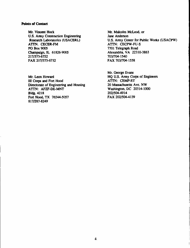
Points of Contact
Mr. Vincent Hock Mr. Malcolm McLeod, orU.S. Army Construction Engineering Jane AndersonResearch Laboratories (USACERL) U.S. Army Center for Public Works (USACPW)
ATTN. CECER-FM ATTN: CECPW-FU-SPO Box 9005 7701 Telegraph RoadChampaign, IL 61826-9005 Alexandria, VA 22310-3863217/373-6752 7031704-1540FAX 217/373-6732 FAX 703/704-1558
Mr. George EvansMr. Leon Howard HQ U.S. Army Corps of EngineersIII Corps and Fort Hood ATI'N: CEMP-ETDirectorate of Engineering and Housing 20 Massachusetts Ave. NWATTN: AFZF-DE-MNT Washington, DC 20314-1000Bldg. 4218 202/504-4914Fort Hood, TX 76544-5057 FAX 202/504-4139817/287-8249
4

2 PRE-ACQUISITION
Description of the Technology
The corrosion control acceptance criteria for impressed current type CP systems used on elevatedwater storage tanks provides guidelines for the DEH/DPW cathodic protection installation inspectors whoseresponsibilities are to ensure that the materials and equipment specified are delivered to the job site andsubsequently installed in accordance with the engineering drawings and specifications. The acceptancecriteria for impressed current CP systems used on water tanks lists all components for the impressedcurrent system, such as the rectifier, anodes, insulated conductors, and ancillary equipment. The CPacceptance criteria is composed of a checklist of each component. The inspector checks either "yes" or"no" to indicate whether the components comply with the job specifications. In some cases, the inspectorwill measure and record physical dimensions or electrical output, and compare those measurements tostandards shown in attached tables.
Before installation, the DEH/DPW inspector must review the engineering drawings for the CPsystem, study the specifications for the components and materials to be used, and become familiar withthe installation procedures identified in the engineering drawings and specifications.
For a CP system to function properly, the proper materials must be delivered to the job site. Thecomponents and materials needed for the CP system should be inspected. Section 1.3 of the Appendixto this guide contains the appropriate checklist on components and materials for the DEH/DPW or COEinspector to fill out. During the installation of the CP system, the inspector should fill out the checklistcontained in Section 1.4 of the Appendix.
Once the CP system is installed and ready for operation, it is necessary to ensure that additionalcriteria are met. With regards to commissioning the CP system, it normally takes some time forpolarization to take place on the structure surface. Generally, cathodic polarization is indicated by achange in the potential of a structure with respect to a reference electrode. After energizing the system,rectifier readings should be checked immediately and monthly thereafter, and structure-to-environmentpotential surveys should be made annually. Section 1.4, Nos. 20-25 of the Appendix contains questionsfor the inspector to fill out during commissioning of the CP system.
Life-Cycle Costs and Benefits
The use of acceptance criteria for impressed current CP systems used on water tanks will reduce thecosts associated with the replacement of installed (usually submerged) CP system components that failprematurally due to improper materials selection or installation. If acceptance criteria is not followed, thiscould lead to the replacement of an entire CP system due to incorrect installation of an anode or anodelead wire at an average cost (for a typical water storage tank) of $15K. In addition, the corrosion damageand high repair or replacement cost of the structure can be avoided when using the impressed current CPacceptance criteria.
5

3 ACQUISITION/PROCUREMENT
Potential Funding Sources
The "Acceptance Criteria for Impressed-Current-Type Cathodic Protection Systems Used To MitigateCorrosion on Water-Storage Tank Interiors" is provided free of charge to Army installations.
Technology Components and Sources
The acceptance criteria for impressed current CP systems used on water tanks checklist can be filledout by any qualified COE or DEH/DPW inspector.
Procurement Documents
The most current version of Corps of Engineers Guide Specifications (CEGS) 16641, "CathodicProtection System (Steel Water Tanks, 2/89)" and 16642, "Cathodic Protection System, (ImpressedCurrent, 3/89)" should be followed when the CP system is being designed and installed. The CP systemshould follow the guidance contained in TM 5-811-7, Electrical Design, Cathodic Protection, and ETL1110-9-10, "Cathodic Protection System Using Ceramic Anodes." A USACERL Draft Technical Report,Cathodic Protection Acceptance Criteria: A Guide for Directorate of Engineering and Housing (DEH)Inspectors, should be reviewed for a more in-depth look at CP systems and the needed emphasis foracceptance criteria.
Procurement Scheduling
Procurement scheduling should include training for one or more Army post DEH/DPW staffmembers to become qualified to complete the acceptance criteria checklist. DEH/DPW personnel canbecome qualified inspectors by attending the Facilities Engineering Corrosion Course taught at USACERLin April or May of each year. Although attendance of the corrosion course is not required of theinspectors, it is highly recommended. Other training sources are PROSPECT course No. 009, CorrosionControl and National Association of Corrosion Engineers (NACE) weeklong courses, CathodicProtection-An Introduction and Cathodic Protection-Theory and Data Interpretation.
6

4 POST-ACQUISITION
Initial Implementation
The acceptance criteria inspections for impressed current CP systems used on water tanks need tobe performed in three stages. First, the materials and supplies for the CP system should be inspected whenthey arrive. Second, an inspection should take place during the installation of the CP system. Third, afinal inspectiof, needs to be done immediately, and again 2 months after the system has been in operation.
Operation and Maintenance of the Technology
The acceptance criteria checklist for impressed current CP systems used on water tanks should befilled out by a qualified DEH/DPW inspector. There is no maintenance involved in this technology.
Service and Support Requirements
The acceptance criteria recommends that a qualified COE or DEH/DPW inspector fill out thechecklist. The COE or DEH/DPW inspector needs to attend a Facilities Engineering Corrosion Courseheld at USACERL in the spring or early summer to become qualified. There is no tuition charge for theI-week course for Department of Defense (DOD) personnel. Other training sources am listed in"Procurement Scheduling" (p 6).
Performance Monitoring
The performance of the acceptance criteria for impressed current CP systems used on water tankscan be measured by comparing results from the checklist with the actual performance of the CP system.A favorable performance would include a good correspondence between the evaluation and the system'sperformance, in other words, a property working CP system with most of the criteria for acceptance met,or a malfunctioning CP system with few of the criteria for acceptance met.
7

APPENDIX: Acceptance Criteria for Impressed-Current-Type, Cathodic Protection SystemsUkd To Mitigate Corrosion on Water Storage Tank Interiors
This appendix contains the checklist that the DEH/DPW inspector is to use when an impressedcurrent type CP system is to be installed on a water storage tank. Some questions may not be applicablefor all impressed current type applications.
1.0 Introduction
The components and materials for an impressed-current type, CP system (e.g., the rectifier, anodes,insulated conductors, and ancillary equipment) used to mitigate corrosion on water-storage tank interiorsand their installation must he rroperly specified and detailed on engineering drawings. Specifiedcomponents and materials must also be delivered to the job site and installed in strict accordance with thespecifications and engineering drawings. Otherwise, when it is commissioned, the CP system may notachieve its intended objective of mitigating corrosion.
This guide/checklist can help the inspector who is responsible for ensuring that the components andmaterials specified for an impressed-current-type. CP system for water tanks are delivered to the job sites.The guide/checklist further provides a convenient way to ensure and document that these components andmaterials are installed according to the specifications and engineering drawings.
1.2 General
Before installation, the inspector must review the engineering drawings for the CP system, study thespecifications for the components and materials to be used, and become thoroughly familiar with theinstallation procedures identified in the specifications and engineering drawings.
1.3 Components/Materials Delivered to the Job Site
With regards to the components and materials delivered to the job site, the inspector should recordanswers to the following questions:
YES NO N/A
1. Was a sufficient number of anodes of the type(s) specified delivered tothe job site?
Number of Anodes:
Anode Types:
2. Were the weights and/or dimensions of the anodes within ±10 percentof those specified or identified on the engineering drawings? In thisregard, dimensional and weight data are summarized for anodes usedinside water storage tanks in Tables Al through A5."
"All Tables and Figures are included at the end of this Appendix.
8

YES NO N/A
3. Based upon the certified chemical analysis reports furnished by theanode manufacturer or supplier, did the anodes satisfy the chemicalcomposition requirements of the specifications and/or engineeringdrawings?
4. If all of the anodes were to have the same insulated-conductor length(i.e., the length of the cable attached to each anode), what was thislength on the anodes delivered to the job site?
Cable Length:
5. If the anodes were to have different cable lengths, what were theselengths on the anodes delivered to the job site?
Cable Lengths:
6. Were the anode-cable lengths at least as long as that required by thespecifications and/or engineering drawings and not too long; i.e., sothat the anodes do not touch the tank wall?
7. Did any of the anode cables contain any splices?
8. Did the copper conductors on the anode cables have the specifiednumber of strands?
Number of Strands:
9. Did the copper conductors on the anode cables have the size requiredby the specifications and/or engineering drawings? In this regard,information on conductor sizes is included in Table A6.
Conductor Size(s):
10. Did the anode cables have the specified type(s) and thickness(es) ofinsulation? In this regard, information on insulation for cathodicprotection cable is included in Table A7.
Type(s) and Thickness(es):
11. What were the copper-conductor size(s), insulation thickness(es), andinsulation type(s) for the header cable (i.e., the primary or mainconductor to which each of the anode conductors was to be attached)on the CP system?
Conductor Size(s):
Insulation Type(s):
Insulation Thickness(es):
12. Did the header cable(s) satisfy the requirements of the specificationsand/or engineering drawings?
13. Did the insulation on the anode or header cables have any defects ornicks that extended below the outer surface more than 20 percent ofthe insulation thickness?
14. Was the external sealing component(s) at the anode ends from whichthe connecting cables exited in accordance with the specificationsand/or engineering drawings?
9

YES NO N/A
15. How were the electrical connections between the anode cables and theheader cable(s) to be made?
Crimp Connector:
Exothermic Weld:
Other; Identify:
16. It the copper conductors on the anode cables were to be exothermicallywelded to the copper conductor(s) on the header cable(s), what wasthe weld-metal-part number and the mold-part number to be used?
Weld-Metal-Part Number:
Mold-Number:
17. It the copper conductors on the anode cables were to be attached ýothe copper conductor(s) on the header cable(s) using crimp-typeconnectors, who was the manufacturer and what was themanufacturer's catalog number for the crimp-type connector(s)?
Manufacturer:
Catalog Number:
18. Were the crimp-type connectors to be used in accordance with themanufacturer's recommendations for the conductor sizes involved?
19. Were the manufacturer's recommended devices and tools available atthe job site for making electrical connections using crimp-typeconnectors?
20. Were the required number and type(s) of splice kits delivered to the jobsite for waterproofing the electrical connections (above thehigh-waterline in the tank) between the anode cables and the headercable(s)?
Manufacturer of Splice Kit:
Catalog Number of Splice Kit:
21. How was the copper conductor on the cable to the direct current powersource to be connected to the cathodically protected structure?
Exothermically Welded:
Brazed:
Other; Identify:
22. If the copper conductor on the cable to the direct current power sourcewas to be exothermically welded to the cathodically protected structure,what was the mold-part number and the weld-metal-part number to beused?
Weld-Metal-Part Number:
Mold-Part Number:
10

YES NO N/A
23. Was the weld-metal-part number and the mold-part number to be usedin exothermically welding the copper conductor from the direct currentpower source to the cathodically protected structure in accordance withthe manufacturer's recommendations?
24. If the anodes were to be supported from the roof of the tank, were theproper components for the supr o.1 system (including any hand holecovers) delivered to the job sit,
25. If the anodes were to be supported using a technique other than theroof-support concept, were the proper components for the supportsystem delivered to the job site?
26. If access to the tank for the anode cables was to be made using apressure-entrance fitting, was the proper device delivered to the jobsite?
27. If permanently-installed, reference electrodes were to be installed, wasthe required number of these delivered to the job site and did each ofthese have a potential within ±7 millivolts of a calibrated referenceelectrode of the same type?
28. Was the specified direct current power source delivered to the job site?
29. If the direct current power source delivered to the job site was arectifier, who was the manufacturer and what was the manufacturer'smodel number?
Manufacturer:
Model Number:
30. If the direct current power source delivered to the job site was arectifier, did the model delivered satisfy the requirements of thespecifications and/or engineering drawings? In general, the modelnumber can be used to identify the characteristics of the rectifier (e.g.,see Figure Al).
31. Was there any evidence of damage to the direct current power sourceor rectifier delivered to the job site?
32. Was the direct current power source or rectifier altered or modified atthe job site?
33. Was adequate equipment available at the job site to successfully installthe CP system?
11

1.4 Installation of the Components/Materials
With regards to the installation of an impressed-current type CP system for water storage tankinteriors, the inspector should record answers to the following questions:
YES NO N/A
1. Was a corrosion engineer at the job site to supervise and inspect theinstallation of the CP system?
2. Wh•at was the name of the corrosion engineer at the job site?
Name:
3. Was the corrosion engineer a professional engineer and/or a NationalAssociation of Corrosion Engineers' "Corrosion Specialist" with suitableexperience in corrosion control for the inside surfaces of water storagetanks?
"4- Did the corrosion engineer remain at the job site the time required toensure that the CP system was installed, tested, and placed in servicein accordance with the specifications and/or engineering drawings?
5. Did the contractor submit a certified test report showing that theanode-to-cable connecting method had passed a 120-day laboratorytest without failure at the place of connection wherein the anode(s) wassubjected to maximum recommended current output while immersed in3 percent sodium chloride solution?
6. Excluding the riser, were the anodes installed within 6 in. of thelocations identified on the engineering drawings with regards to thewater storage tank bottom and wall?
7. If a riser on the water-storage tank was to be cathodically protected,was the top and bottom of the anode or anode string within ±6 in. ofthat identified on the engineering drawings and was the anode oranode string centered within ±10 percent of the centerline of the riser?
8. Was the support system for the anode(s) in accordance with theengineering drawings?
9. Were the anodes connected to the header cable(s) using the propercomponents and the procedures identified in the engineering drawings?
10. Was the negative cable to the rectifier or direct current power sourceelectrically coqnected to the water storage tank in accordance with theengineering drawings?
11. If installed, was the permanently-installed, reference electrode(s)positioned within 6 in. of the location(s) identified on the engineeringdrawings?
12. If Installed, was the "sensing window" for the permanently-installed,reference electrode(s) located between 0.25 and 0.5 in. away from thetank surface? (If it is impractical for the inspector to measure thedistance of the reference electrode to tank wall, the IR face or off-potential readings must be taken.)
12

YES NO N/A
13. Was the rectifier mounted in accoidance with the engineeringdrawings?
14. Did the grounding system for the rectifier cabinet have aresistance-to-earth of not more than 25 ohms?
15. If the direct current power source was a rectifier, was a dedicatedalternating-current supply provided?
16. Was the copper conductor(s) on the anode system connected to thepositive output terminal on the direct current power source?
17. If installed, was the anode junction and/or anode (variable) resistor boxinstalled in accordance with the engineering drawings?
18. If one was installed and with the tank filled with water, were any leaksobserved at the site of the pressure-entrance fitting?
19. Was a structure-to-water potential survey conducted for the water-storage tank before the direct current power source was activated? Ifso, include these data as an attachment to this report, using the format:
Structure-to-Water Potential,Test Location Volt vs, Copper-Copper Sulfate
20. Upon activation of the direct current power source, was an IR-error-free, structure-to-water potential survey conducted to ensure that thewate~side surfaces of the tank were adequately protected withoutoveprotection? In this regard, an IR-error-free potential of -0.85 voltreferenced to copper-copper sulfate is considered to be adequateprotection; a potential more negative than -1.2 volts is considered to beoverprotection. Attach a copy of the structure-to-water potential surveyto this report, using the format:
Structure-to-Water Potential,Test Location Volt vs, Copper-Copper Sulfate
21. If a structure-to-water potential survey was conducted after activation ofthe direct current power source was activated and (possibly) adjusted,what was the output voltage and output current for the direct currentpower source? What was the current output to each of the anodecircuits?
Output Voltage:
Current Output(s):
22. If a structure-to-water potential survey was conducted after finaladjustment of the direct current power source, record the results on aseparate sheet of paper and attach it to this report.
Potential Survey Conducted?
Survey Results Attached?
23. Did the contractor provide the operating instructions, maintenanceinstructions, spare parts, training course, and performance test report(s)for the CP system required by the contract?
13

24. Record the dates that the inspector was inside the water storage tank
for the purpose of inspection:
Dates:
25. Record the dates that the inspector was at the job site for inspectionthat did not require entrance into the tank.
Dates:
14

Table AI
Segmented, Solid Cylindrical, Mixed-Metal Oxide Activated TitaniumAnodes for Impressed-Current-Type Cathodic Protection Systems
Anode Length (in.) Anode Diameter (in.)
24" 0.13848" 0.13872" 0.13896" 0.13824" 0.13848- 0.13872" 0.13896" 0.138
* Solid titanium substrate
** Copper/niobium/titanium substrate
Table A2
Tubular, Mixed-Metal Oxide Activated Titanium Anodes forImpressed-Current-Type Cathodic Protection Systems In Fresh Water
Diameter (in.) Length (in.)
1.0 39.7
1.0 39.4
0.63 19.7
0.63 39.4
Table A3
Standard Solid Cylindrical, High-Silicon Chromium-Bearing CastIron Anodes for Impressed-Current-Type Cathodic Protection Systems
Anode Type Diameter (in.) Length (in.) Weight (Ib) Surface Area (sq ft)
B 1.0 60 12 1.4C 1.5 60 25 2.0
CD 1.5 60 26 2.0CDD 1.5 60 26 2.0
D 2.0 60 44 2.6M 2.0 60 60 2.81 3.0 36 80 2.5E 3.0 60 110 4.0
SM 4.5 60 220 5.5
15

Table A4
Tubular, High-Silicon Chromium-Bearing Cast Iron Anodesfor Impressed-Current-Type Cathodic Protection Systems'
Anode Type Outside Dia. (in.) Length (in.) Wall Thickness (in.) Weight (Ib) Surface Area (sq ft)
TAI 2.66 42 0.41 31 2.4TA2 2,19 84 0.41 46 4TA3 2.66 84 0.41 63 4.9TA4 3.75 84 0.41 85 6.9TA5 4.75 84 0.41 110 8.7
TA5A 4.75 84 0.69 175 8&7
Center connections for tubular anodes eliminates loss due to "end effects" with solid cylindrical anodes.
Table A5
Special, High-Silicon Chromium-Bearing Cast Iron Anodesfor Impressed-Current-Type Cathodic Protection Systems
Anode Type Diameter (in.) Length (in.) Weight (Ib) Surface Area (sq ft)
FW 1.1 9 1.0 0.2FC 1.5 9 4.0 0.3G 2.0 9 5.0 0.4
B-30 1.0 30 7.0 0.7C-30 1.5 30 12.5 1.0
CD-30 1.5 30 13.0 1.0M-30 2.0 30 30.0 1.3
16

Table A6
Diameters for Concentric-Lay Stranded andSolid Standard Annealed Copper Conductors
Conductor Size, Diameter, Solid Diameter, StrandedAWG/MCM Conductor (in.)" Conductor (in)-
350"" 0.681350"" 0.630350" - 0.5754/0 0.460 0.5283/0 0.4096 0.4702/0 0.3648 0.4180 0.3249 0.373I 0.2893 0.3322 0.2576 0.2923 0.2294 0.2604 0.2043 0.2326 0.1620 0.1848 0.1285 0.146
10 0.1019 0.11612 0.0808 0.09214 0.0641 0.073
" Without insulation"Thousands of circular mils (MCM)
Table A7
Insulation Thickness for Stranded and Solid Copper Conductors
Conductor Size InsulationInsulation Type (AWG/MCM) Thickness (in.)
Thermoplastic waterproof 10-14 0.030(TW) 8 0.045
6-2 0.0601-4/0 0.080
213-500' 0.095
High molecular wt.Polyethylene (HMWPE) 2-8 0.110
1-4/0 0.12525W0 0.155
DualECTFE'" or PVF" primary 0.020HMWPE secondary 0.065
" Thousands of circular mils (MCM)."Ethylene monochlorotrifluorethylene."Polyvinylidene fluoride. Note: For dual insulation, the primary is theinner insulation; secondary is the outer insulation.
17

Table A8
Commonly-Used Shunts for Cathodic Protection Systems
Type Resistance (Ohm) Capacity (A) Material
JB 0.01 8 Manganin strip
RS 0.01 6 Manganin wire
SO 0.001 50 Manganin wire
SS 0.001 25 Constantan strip
18

GOOD-ALL RECTIFIER MODEL CODES
A - Type A-JB - Type BC - CustomE - Type E
Ist F - Type FLetter J - Jemoo(Type) N- Type N
P - Portable Test NOTE: Code letters may be selectedPV - Photo Voltaic Supply to achieve the desired type, control,S - Service Station circuit cooling. rectifying elements,T - VIP etc. CSAWSA 20-22 AS Model
Code - Custom, Standard. AirA - Amp-O-Matic Cooled, Selenium. SingleI - Constant Current Phase Bridge Rectifier
2nd P - Auto. Potential Control with 20 volts DC andLetter R - IR Drop Free 22 amps DC output.
(Control) S - Standard Rectifier optional 11 gaugeV - Voltage regulated steel encd.l6ureZ - Other (specify) with slide
out rack.A - Air-Cooled (convection)
0 -Oil-Immersedr X - Oil-immersed (explosion proof)Coolete D - SubmersibleCooling) F - Fan-Cooled
Z - Other (specify)
4thLetter W - Selenium Stacks
(Rectifying Y - Silicon StacksElements)
C - Center Tap, Single-PhaseLttr S - Bridge, Single-Phase
Letter Y - eaPhase WyeCircuit) T - Three-Phase Bridge
A - 120 VAC InputB - 208 VAC Input
6th C - 240 VAC InputLettr D - 480 VAC Input
(input) E - 120/240 VAC inputF - 240/480 VAC Input
G - 120/480 VAC InputZ - Other (specify)
Model ICDC Voltage RatingCode
Example DC Current Rating
tOptional Features
C S A W S A 20 22 AS
OPTIONAL FEATURES
A - Slide out rack for transformer & stack. L - Lightning protection for AC input only.C - Cross Ann Mounting. M - Lightning protection for DC output only.D - Legs-Air-cooled only-10' or specify. N - Lightning protection for both inpiv! =1d output.E - Continuous reading meters. P - Special finishes.F - Communication Interference fifter. 0 - Export Crating.G - Efficiency filter. R - Interrupter Circuit.H - Other than standard number of DC Output steps (standard S - Small arms proof (II gauge front, side and back).
has 20 steps) (specify). T - Higher ambient temperatures (specify).J - Flashing signal light (Continuous at normal current, flashing V - Nonstandard access knockouts (specify).
at undercurrent, out at loss of input.) Y - Input frequency other than 60 cycle (specify).K - Continuous signal light. (Out at loss of input, output or at Z - Any other features (specify).
undercurrent.)
Figure AI: Optional Rectifier Features and the Good-All Electric, Inc. Model Code System for Determining theCharacteristics of a Rectifier. (Similar Codes Have Been Established by Other Rectifier Manufacturers.)Reprinted with permission of Good-All Electric, Inc., 3725 Canal Drive, Fort Collins, CO 80524.
19 Cr u.s. GOVERNMENT PRINTING OFFICE: 1994 - 3510-S/00048