Embed Size (px)
Citation preview

IN0A
IN0B
IN3A
IN3B
FDC2114 / FDC2214 VDD
GND
SCL
SDA
Int. Osc.
ADDR
INTB
SD
GND
MCU
VDD
3.3 V3.3 V
GPIO
GPIO
0.1 �F 1 �F
Core
I2CI2C
peripheral
3.3 V
L
Cap Sensor 0
CLKIN40 MHz
C
L
Cap Sensor 3
C
Resonant circuit driver
Resonant circuit driver
Product
Folder
Sample &Buy
Technical
Documents
Tools &
Software
Support &Community
FDC2212, FDC2214, FDC2112, FDC2114SNOSCZ5A –JUNE 2015–REVISED JUNE 2015
FDC2x1x EMI-Resistant 28-Bit,12-Bit Capacitance-to-Digital Converter for Proximity andLevel Sensing Applications
1 Features 3 DescriptionCapacitive sensing is a low-power, low-cost, high-
1• EMI-Resistant Architectureresolution contactless sensing technique that can be• Maximum Output Rates (one active channel): applied to a variety of applications ranging from
– 13.3 ksps (FDC2112, FDC2114) proximity detection and gesture recognition to remoteliquid level sensing. The sensor in a capacitive– 4.08 ksps (FDC2212, FDC2214)sensing system is any metal or conductor, allowing• Maximum Input Capacitance: 250 nF (at 10 kHz for low cost and highly flexible system design.with 1 mH inductor)The main challenge limiting sensitivity in capacitive• Sensor Excitation Frequency: 10 kHz to 10 MHzsensing applications is noise susceptibility of the
• Number of channels: 2, 4 sensors. With the FDC2x1x innovative EMI resistant• Resolution: up to 28 bits architecture, performance can be maintained even in
presence of high-noise environments.• System Noise Floor: 0.3 fF at 100 sps• Supply Voltage: 2.7 V to 3.6 V The FDC2x1x is a multi-channel family of noise- and
EMI-resistant, high-resolution, high-speed• Power Consumption: Active: 2.1 mAcapacitance-to-digital converters for implementing• Low-Power Sleep Mode: 35 uA capacitive sensing solutions. The devices employ an
• Shutdown: 200 nA innovative narrow-band based architecture to offerhigh rejection of noise and interferers while providing• Interface: I2Chigh resolution at high speed. The devices support a• Temperature range: -40°C to +125°C wide excitation frequency range, offering flexibility insystem design. A wide frequency range is especially2 Applications useful for reliable sensing of conductive liquids suchas detergent, soap, and ink.• Proximity Sensor
• Gesture RecognitionDevice Information(1)
• Level Sensor for Liquids, including ConductivePART NUMBER PACKAGE BODY SIZE (NOM)ones such as Detergent, Soap, and Ink
FDC2112, FDC2212 WSON (DNT 12) 4.00 mm x 4.00 mm• Collision Avoidance
FDC2114, FDC2214 WQFN (RGH 16) 4.00 mm x 4.00 mm• Rain, Fog, Ice, Snow Sensor
(1) For all available packages, see the orderable addendum at• Automotive Door and Kick Sensors the end of the datasheet.• Material Size Detection
Simplified Schematic
1
An IMPORTANT NOTICE at the end of this data sheet addresses availability, warranty, changes, use in safety-critical applications,intellectual property matters and other important disclaimers. PRODUCTION DATA.

FDC2212, FDC2214, FDC2112, FDC2114SNOSCZ5A –JUNE 2015–REVISED JUNE 2015 www.ti.com
Table of Contents9.4 Device Functional Modes........................................ 211 Features .................................................................. 19.5 Programming........................................................... 212 Applications ........................................................... 19.6 Register Maps ......................................................... 223 Description ............................................................. 1
10 Application and Implementation........................ 394 Revision History..................................................... 210.1 Application Information.......................................... 395 Description, continued .......................................... 310.2 Typical Application ............................................... 406 Device Comparison Table ..................................... 310.3 Do's and Don'ts..................................................... 467 Pin Configuration and Functions ......................... 4 11 Power Supply Recommendations ..................... 468 Specifications......................................................... 5 12 Layout................................................................... 468.1 Absolute Maximum Ratings ...................................... 512.1 Layout Guidelines ................................................. 468.2 ESD Ratings ............................................................ 512.2 Layout Example .................................................... 468.3 Recommended Operating Conditions....................... 5
13 Device and Documentation Support ................. 518.4 Thermal Information ................................................. 513.1 Device Support...................................................... 518.5 Electrical Characteristics........................................... 613.2 Related Links ........................................................ 518.6 Timing Requirements ................................................ 713.3 Community Resources.......................................... 518.7 Switching Characteristics - I2C ................................. 813.4 Trademarks ........................................................... 518.8 Typical Characteristics .............................................. 913.5 Electrostatic Discharge Caution............................ 519 Detailed Description ............................................ 1113.6 Glossary ................................................................ 519.1 Overview ................................................................. 11
14 Mechanical, Packaging, and Orderable9.2 Functional Block Diagrams ..................................... 11 Information ........................................................... 519.3 Feature Description................................................. 12
4 Revision History
Changes from Original (June 2015) to Revision A Page
• Added full datasheet. ............................................................................................................................................................. 1
2 Submit Documentation Feedback Copyright © 2015, Texas Instruments Incorporated
Product Folder Links: FDC2212 FDC2214 FDC2112 FDC2114

FDC2212, FDC2214, FDC2112, FDC2114www.ti.com SNOSCZ5A –JUNE 2015–REVISED JUNE 2015
5 Description, continued
The FDC221x is optimized for high resolution, up to 28 bits, while the FDC211x offers fast sample rate, up to13.3ksps, for easy implementation of applications that use fast moving targets. The very large maximum inputcapacitance of 250 nF allows for the use of remote sensors, as well as for tracking environmental changes overtime, temperature and humidity.
The FDC2x1x family targets proximity sensing and liquid level sensing applications for any type of liquids. Fornon-conductive liquid level sensing applications in the presence of interferences such as human hands, theFDC1004 is recommended, which has integrated active shield drivers.
6 Device Comparison Table
PART NUMBER RESOLUTION CHANNELS PACKAGEFDC2112 12 bit 2 WSON-12FDC2114 12 bit 4 WQFN-16FDC2212 28 bit 2 WSON-12FDC2214 28 bit 4 WQFN-16
Copyright © 2015, Texas Instruments Incorporated Submit Documentation Feedback 3
Product Folder Links: FDC2212 FDC2214 FDC2112 FDC2114

1
2
3
4
12
11
10
9
5 6 7 8
16 15 14 13
DAP
SCL
SDA
CLKIN
ADDR IN0A
IN0B
IN1A
IN1B
INT
B
SD
VD
D
GN
D
IN3B
IN2B
IN3A
IN2A
DAP
1SCL
3CLKIN
4ADDR
INTB 5
VDD7
GND8
IN0A9
IN0B10
IN1A11
SD 6
IN1B12
2SDA
FDC2212, FDC2214, FDC2112, FDC2114SNOSCZ5A –JUNE 2015–REVISED JUNE 2015 www.ti.com
7 Pin Configuration and Functions
FDC2112/FDC2212 WSONDNT-12
Top View
FDC2114/FDC2214 WQFNRGH-16
Top View
Pin FunctionsPIN
TYPE (1) DESCRIPTIONNAME NO.SCL 1 I I2C Clock inputSDA 2 I/O I2C Data input/outputCLKIN 3 I Master Clock input. Tie this pin to GND if internal oscillator is selected
I2C Address selection pin: when ADDR=L, I2C address = 0x2A, when ADDR=H, I2C address =ADDR 4 I 0x2B.INTB 5 O Configurable Interrupt output pinSD 6 I Shutdown inputVDD 7 P Power SupplyGND 8 G GroundIN0A 9 A Capacitive sensor input 0IN0B 10 A Capacitive sensor input 0IN1A 11 A Capacitive sensor input 1IN1B 12 A Capacitive sensor input 1IN2A 13 A Capacitive sensor input 2 (FDC2114 / FDC2214 only)IN2B 14 A Capacitive sensor input 2 (FDC2114 / FDC2214 only)
(1) I = Input, O = Output, P=Power, G=Ground, A=Analog
4 Submit Documentation Feedback Copyright © 2015, Texas Instruments Incorporated
Product Folder Links: FDC2212 FDC2214 FDC2112 FDC2114

FDC2212, FDC2214, FDC2112, FDC2114www.ti.com SNOSCZ5A –JUNE 2015–REVISED JUNE 2015
Pin Functions (continued)PIN
TYPE (1) DESCRIPTIONNAME NO.IN3A 15 A Capacitive sensor input 3 (FDC2114 / FDC2214 only)IN3B 16 A Capacitive sensor input 3 (FDC2114 / FDC2214 only)DAP (2) DAP N/A Connect to Ground
(2) There is an internal electrical connection between the exposed Die Attach Pad (DAP) and the GND pin of the device. Although the DAPcan be left floating, for best performance the DAP should be connected to the same potential as the device's GND pin. Do not use theDAP as the primary ground for the device. The device GND pin must always be connected to ground.
8 Specifications
8.1 Absolute Maximum RatingsMIN MAX UNIT
VDD Supply voltage range 5 VVi Voltage on any pin –0.3 VDD + 0.3 VIA Input current on any INx pin –8 8 mAID Input current on any digital pin –5 5 mATJ Junction temperature –55 150 °CTstg Storage temperature –65 150 °C
(1) Stresses beyond those listed under Absolute Maximum Ratings may cause permanent damage to the device. These are stress ratingsonly, which do not imply functional operation of the device at these or any other conditions beyond those indicated under RecommendedOperating Conditions. Exposure to absolute-maximum-rated conditions for extended periods may affect device reliability.
8.2 ESD RatingsVALUE UNIT
FDC2112 / FDC2212 in 12-pin WSON packageHuman-body model (HBM), per ANSI/ESDA/JEDEC JS-001 (1) ±2000
V(ESD) Electrostatic discharge VCharged-device model (CDM), per JEDEC specification JESD22- ±750C101 (2)
FDC2114 / FDC2214 in 16-pin WQFN packageHuman-body model (HBM), per ANSI/ESDA/JEDEC JS-001 (1) ±2000
V(ESD) Electrostatic discharge VCharged-device model (CDM), per JEDEC specification JESD22- ±750C101 (2)
(1) JEDEC document JEP155 states that 500-V HBM allows safe manufacturing with a standard ESD control process.(2) JEDEC document JEP157 states that 250-V CDM allows safe manufacturing with a standard ESD control process.
8.3 Recommended Operating ConditionsUnless otherwise specified, all limits ensured for TA = 25°C, VDD = 3.3 V
MIN NOM MAX UNITVDD Supply voltage 2.7 3.6 VTA Operating temperature –40 125 °C
8.4 Thermal InformationFDC2112 / FDC2214 /FDC2212 FDC2214
THERMAL METRIC (1) UNITDNT (WSON) RGH (WQFN)12 PINS 16 PINS
RθJA Junction-to-ambient thermal resistance 50 38 °C/W
(1) For more information about traditional and new thermal metrics, see the Semiconductor and IC Package Thermal Metrics applicationreport, SPRA953.
Copyright © 2015, Texas Instruments Incorporated Submit Documentation Feedback 5
Product Folder Links: FDC2212 FDC2214 FDC2112 FDC2114

FDC2212, FDC2214, FDC2112, FDC2114SNOSCZ5A –JUNE 2015–REVISED JUNE 2015 www.ti.com
8.5 Electrical CharacteristicsUnless otherwise specified, all limits ensured for TA = 25°C, VDD = 3.3 V (1)
PARAMETER TEST CONDITIONS (2) MIN (3) TYP (4) MAX (3) UNITPOWERVDD Supply voltage TA = –40°C to +125°C 2.7 3.6 VIDD Supply durrent (not including CLKIN = 10MHz (6)
2.1 mAsensor current) (5)
IDDSL Sleep mode supply current (5) 35 60 µAISD Shutdown mode supply current (5) 0.2 1 µACAPACITIVE SENSORCSENSORMAX Maximum sensor capacitance 1mH inductor, 10kHz oscillation 250 nFCIN Sensor pin parasitic capacitance 4 pFNBITS Number of bits FDC2112, FDC2114 12 bitsRCOUNT ≥ 0x0400
FDC2212, FDC2214 28 bitsRCOUNT = 0xFFFFfCS Maximum channel sample rate FDC2112, FDC2114
single active channel continuous 13.3 kSPSconversion, SCL = 400 kHzFDC2212, FDC2214single active channel continuous 4.08 kSPSconversion, SCL= 400 kHz
EXCITATIONfSENSOR Sensor excitation frequency TA = –40°C to +125°C 0.01 10 MHzVSENSORMIN Minimum sensor oscillation 1.2 Vamplitude (pk) (7)
VSENSORMAX Maximum sensor oscillation 1.8 Vamplitude (pk)ISENSORMAX Sensor maximum current drive HIGH_CURRENT_DRV = b0
DRIVE_CURRENT_CH0 = 1.5 mA0xF800HIGH_CURRENT_DRV = b1DRIVE_CURRENT_CH0 = 6 mA0xF800Channel 0 only
MASTER CLOCKfCLKIN External master clock input TA = –40°C to +125°C 2 40 MHzfrequency (CLKIN)CLKINDUTY_MIN External master clock minimum 40%acceptable duty cycle (CLKIN)CLKINDUTY_MAX External master clock maximum 60%acceptable duty cycle (CLKIN)VCLKIN_LO CLKIN low voltage threshold 0.3*VDD V
(1) Electrical Characteristics values apply only for factory testing conditions at the temperature indicated. Factory testing conditions result invery limited self-heating of the device such that TJ = TA. No guarantee of parametric performance is indicated in the electrical tablesunder conditions of internal self-heating where TJ > TA. Absolute Maximum Ratings indicate junction temperature limits beyond whichthe device may be permanently degraded, either mechanically or electrically.
(2) Register values are represented as either binary (b is the prefix to the digits), or hexadecimal (0x is the prefix to the digits). Decimalvalues have no prefix.
(3) Limits are ensured by testing, design, or statistical analysis at 25°C. Limits over the operating temperature range are ensured throughcorrelations using statistical quality control (SQC) method.
(4) Typical values represent the most likely parametric norm as determined at the time of characterization. Actual typical values may varyover time and will also depend on the application and configuration. The typical values are not tested and are not ensured on shippedproduction material.
(5) I2C read/write communication and pull-up resistors current through SCL, SDA not included.(6) Sensor capacitor: 1 layer, 20.9 x 13.9 mm, Bourns CMH322522-180KL sensor inductor with L=18µH and 33pF 1% COG/NP0 Target:
Grounded aluminum plate (176 x 123 mm), Channel = Channel 0 (continuous mode) CLKIN = 40 MHz, CHx_FIN_SEL = b10,CHx_FREF_DIVIDER = b00 0000 0001 CH0_RCOUNT = 0xFFFF, SETTLECOUNT_CH0 = 0x0100, DRIVE_CURRENT_CH0 = 0x7800.
(7) Lower VSENSORMIN oscillation amplitudes can be used, but will result in lower SNR.
6 Submit Documentation Feedback Copyright © 2015, Texas Instruments Incorporated
Product Folder Links: FDC2212 FDC2214 FDC2112 FDC2114

SCL
SDA
tHD;STA
tLOW
tr
tHD;DAT
tHIGH
tf
tSU;DAT
tSU;STA tSU;STO
tf
START REPEATEDSTART
STOP
tHD;STA
START
tSP
trtBUF
FDC2212, FDC2214, FDC2112, FDC2114www.ti.com SNOSCZ5A –JUNE 2015–REVISED JUNE 2015
Electrical Characteristics (continued)Unless otherwise specified, all limits ensured for TA = 25°C, VDD = 3.3 V(1)
PARAMETER TEST CONDITIONS (2) MIN (3) TYP (4) MAX (3) UNITVCLKIN_HI CLKIN high voltage threshold 0.7*VDD VfINTCLK Internal master clock frequency 35 43.4 55 MHzrangeTCf_int_μ Internal master clock temperature –13 ppm/°Ccoefficient mean
8.6 Timing RequirementsMIN NOM MAX UNIT
tSDWAKEUP Wake-up time from SD high-low transition to I2C readback 2 mstSLEEPWAKEUP Wake-up time from sleep mode 0.05 mstWD-TIMEOUT Sensor recovery time (after watchdog timeout) 5.2 msI2C TIMING CHARACTERISTICSfSCL Clock frequency 10 400 kHztLOW Clock low time 1.3 μstHIGH Clock high time 0.6 μs
Hold time (repeated) START condition: after this period, the first clocktHD;STA 0.6 μspulse is generatedtSU;STA Setup time for a repeated START condition 0.6 μstHD;DAT Data hold time 0 μstSU;DAT Data setup time 100 nstSU;STO Setup time for STOP condition 0.6 μstBUF Bus free time between a STOP and START condition 1.3 μstVD;DAT Data valid time 0.9 μstVD;ACK Data valid acknowledge time 0.9 μstSP Pulse width of spikes that must be suppressed by the input filter (1) 50 ns
(1) This parameter is specified by design and/or characterization and is not tested in production.
Figure 1. I2C Timing
Copyright © 2015, Texas Instruments Incorporated Submit Documentation Feedback 7
Product Folder Links: FDC2212 FDC2214 FDC2112 FDC2114

FDC2212, FDC2214, FDC2112, FDC2114SNOSCZ5A –JUNE 2015–REVISED JUNE 2015 www.ti.com
8.7 Switching Characteristics - I2CUnless otherwise specified, all limits ensured for TA = 25°C, VDD = 3.3 V
PARAMETER TEST CONDITIONS MIN TYP MAX UNITVOLTAGE LEVELSVIH Input high voltage 0.7ˣVDD VVIL Input low voltage 0.3ˣVDD VVOL Output low voltage (3 mA sink 0.4 Vcurrent)HYS Hysteresis 0.1ˣVDD V
8 Submit Documentation Feedback Copyright © 2015, Texas Instruments Incorporated
Product Folder Links: FDC2212 FDC2214 FDC2112 FDC2114

Temperature (°C)
Shu
tdow
n C
urre
nt (
µA
)
-40 -20 0 20 40 60 80 100 1200
0.2
0.4
0.6
0.8
1
1.2
1.4
D007
VDD = 2.7 VVDD = 3 VVDD = 3.3 VVDD = 3.6 V
VDD (V)
Shu
tdow
n C
urre
nt (
µA
)
2.7 2.8 2.9 3 3.1 3.2 3.3 3.4 3.5 3.60
0.2
0.4
0.6
0.8
1
1.2
1.4
1.6
D008
-40°C-20°C
0°C25°C
50°C85°C
100°C125°C
Temperature (°C)
Sle
ep C
urre
nt (
µA
)
-40 -20 0 20 40 60 80 100 12025
30
35
40
45
50
55
60
D005
VDD = 2.7 VVDD = 3 VVDD = 3.3 VVDD = 3.6 V
VDD (V)
Sle
ep C
urre
nt (
µA
)
2.7 2.8 2.9 3 3.1 3.2 3.3 3.4 3.5 3.625
30
35
40
45
50
55
60
65
D006
-40°C-20°C
0°C25°C
50°C85°C
100°C125°C
Temperature (°C)
IDD
CH
0 C
urre
nt (
mA
)
-40 -20 0 20 40 60 80 100 1203.05
3.075
3.1
3.125
3.15
3.175
3.2
3.225
3.25
D003
VDD = 2.7 VVDD = 3 VVDD = 3.3 VVDD = 3.6 V
VDD (V)
IDD
CH
0 C
urre
nt (
mA
)
2.7 2.8 2.9 3 3.1 3.2 3.3 3.4 3.5 3.63.05
3.1
3.15
3.2
3.25
D004
-40°C-20°C0°C25°C
50°C85°C100°C125°C
FDC2212, FDC2214, FDC2112, FDC2114www.ti.com SNOSCZ5A –JUNE 2015–REVISED JUNE 2015
8.8 Typical CharacteristicsCommon test conditions (unless specified otherwise): Sensor capacitor: 1 layer, 20.9 x 13.9 mm, Bourns CMH322522-180KLsensor inductor with L=18 µH and 33 pF 1% COG/NP0 Target: Grounded aluminum plate (176 x 123 mm), Channel =Channel 0 (continuous mode) CLKIN = 40 MHz, CHx_FIN_SEL = b01, CHx_FREF_DIVIDER = b00 0000 0001CH0_RCOUNT = 0xFFFF, SETTLECOUNT_CH0 = 0x0100, DRIVE_CURRENT_CH0 = 0x7800.
Includes 1.57 mA sensor current Includes 1.57 mA sensor current–40°C to +125°C
Figure 2. Active Mode IDD vs. Temperature Figure 3. Active Mode IDD vs. VDD
–40°C to +125°C
Figure 4. Sleep Mode IDD vs. Temperature Figure 5. Sleep Mode IDD vs. VDD
–40°C to +125°C
Figure 6. Shutdown Mode IDD vs. Temperature Figure 7. Shutdown Mode IDD vs. VDD
Copyright © 2015, Texas Instruments Incorporated Submit Documentation Feedback 9
Product Folder Links: FDC2212 FDC2214 FDC2112 FDC2114

Temperature (°C)
Inte
rnal
Osc
illat
or (
MH
z)
-40 -20 0 20 40 60 80 100 12043.32
43.33
43.34
43.35
43.36
43.37
43.38
43.39
43.4
D009
VDD = 2.7 VVDD = 3 VVDD = 3.3 VVDD = 3.6 V
VDD (V)
Inte
rnal
Osc
illat
or (
MH
z)
2.7 2.8 2.9 3 3.1 3.2 3.3 3.4 3.5 3.643.32
43.33
43.34
43.35
43.36
43.37
43.38
43.39
43.4
43.41
D010
-40°C-20°C
0°C25°C
50°C85°C
100°C125°C
FDC2212, FDC2214, FDC2112, FDC2114SNOSCZ5A –JUNE 2015–REVISED JUNE 2015 www.ti.com
Typical Characteristics (continued)Common test conditions (unless specified otherwise): Sensor capacitor: 1 layer, 20.9 x 13.9 mm, Bourns CMH322522-180KLsensor inductor with L=18 µH and 33 pF 1% COG/NP0 Target: Grounded aluminum plate (176 x 123 mm), Channel =Channel 0 (continuous mode) CLKIN = 40 MHz, CHx_FIN_SEL = b01, CHx_FREF_DIVIDER = b00 0000 0001CH0_RCOUNT = 0xFFFF, SETTLECOUNT_CH0 = 0x0100, DRIVE_CURRENT_CH0 = 0x7800.
–40°C to +125°C Data based on 1 unit
Figure 8. Internal Oscillator Frequency vs. Temperature Figure 9. Internal Oscillator Frequency vs. VDD
10 Submit Documentation Feedback Copyright © 2015, Texas Instruments Incorporated
Product Folder Links: FDC2212 FDC2214 FDC2112 FDC2114

IN0A
IN0B
IN1A
IN1B
FDC2112 / FDC2212 VDD
GND
SCL
SDA
Int. Osc.
ADDR
INTB
SD
GND
MCU
VDD
3.3 V3.3 V
GPIO
GPIO
0.1 �F 1 �F
Core
Resonant circuit driver
Resonant circuit driver
I2CI2C
peripheral
3.3 V
L
Cap Sensor 0
CLKIN40 MHz
C
L
Cap Sensor 1
C
FDC2212, FDC2214, FDC2112, FDC2114www.ti.com SNOSCZ5A –JUNE 2015–REVISED JUNE 2015
9 Detailed Description
9.1 OverviewThe FDC2112, FDC2114, FDC2212, and FDC2214 are high-resolution, multichannel capacitance-to-digitalconverters for implementing capacitive sensing solutions. In contrast to traditional switched-capacitancearchitectures, the FDC2112, FDC2114, FDC2212, and FDC2214 employ an L-C resonator, also known as L-Ctank, as a sensor. The narrow-band architecture allows unprecedented EMI immunity and greatly reduced noisefloor when compared to other capacitive sensing solutions.
Using this approach, a change in capacitance of the L-C tank can be observed as a shift in the resonantfrequency. Using this principle, the FDC is a capacitance-to-digital converter (FDC) that measures the oscillationfrequency of an LC resonator. The device outputs a digital value that is proportional to frequency. This frequencymeasurement can be converted to an equivalent capacitance
9.2 Functional Block Diagrams
Figure 10. Block Diagram for the FDC2112 and FDC2212
Copyright © 2015, Texas Instruments Incorporated Submit Documentation Feedback 11
Product Folder Links: FDC2212 FDC2214 FDC2112 FDC2114

IN0A
IN0B
IN3A
IN3B
FDC2114 / FDC2214 VDD
GND
SCL
SDA
Int. Osc.
ADDR
INTB
SD
GND
MCU
VDD
3.3 V3.3 V
GPIO
GPIO
0.1 �F 1 �F
Core
I2CI2C
peripheral
3.3 V
L
Cap Sensor 0
CLKIN40 MHz
C
L
Cap Sensor 3
C
Resonant circuit driver
Resonant circuit driver
FDC2212, FDC2214, FDC2112, FDC2114SNOSCZ5A –JUNE 2015–REVISED JUNE 2015 www.ti.com
Functional Block Diagrams (continued)
Figure 11. Block Diagrams for the FDC2114 and FDC2214
The FDC is composed of front-end resonant circuit drivers, followed by a multiplexer that sequences through theactive channels, connecting them to the core that measures and digitizes the sensor frequency (fSENSOR). Thecore uses a reference frequency (fREF) to measure the sensor frequency. fREF is derived from either an internalreference clock (oscillator), or an externally supplied clock. The digitized output for each channel is proportionalto the ratio of fSENSOR/fREF. The I2C interface is used to support device configuration and to transmit the digitizedfrequency values to a host processor. The FDC can be placed in shutdown mode, saving current, using the SDpin. The INTB pin may be configured to notify the host of changes in system status.
9.3 Feature Description
9.3.1 Clocking ArchitectureFigure 12 shows the clock dividers and multiplexers of the FDC.
12 Submit Documentation Feedback Copyright © 2015, Texas Instruments Incorporated
Product Folder Links: FDC2212 FDC2214 FDC2112 FDC2114

fSENSOR3(1)
÷ n
÷ n
CH3_FREF_DIVIDER (0x17)(1)
CH2_FREF_DIVIDER (0x16)(1)
Int. Osc.
Core
tfREFt
Data Output
tfINTt
REF_CLK_SRC (0x1A)
CONFIG (0x1A)MUX_CONFIG (0x1B)
÷ n
÷ n
CH1_FREF_DIVIDER (0x15)
CH0_FREF_DIVIDER (0x14)
tfREF0t
tfREF1t
tfREF2(1)t
tfREF3(1)t
÷ m
÷ m
CH3_FIN_SEL (0x17)(1)
CH2_FIN_SEL (0x16)(1)
tfINt
÷ m
÷ m
CH1_FIN_SEL (0x15)
CH0_FIN_SEL (0x14)
tfIN0t
tfIN1t
tfIN2(1)t
tfIN3(1)t
tfCLKt
CONFIG (0x1A)MUX_CONFIG (0x1B)
IN2A(1)
IN2B(1)
IN3A(1)
IN3B(1)
IN1A
IN1B
IN0A
IN0B
fCLKIN CLKIN
LCap Sensor 3(1)
fSENSOR2(1)
LCap Sensor 2(1)
fSENSOR1
LCap Sensor 1
fSENSOR0
LCap Sensor 0
FDC2212, FDC2214, FDC2112, FDC2114www.ti.com SNOSCZ5A –JUNE 2015–REVISED JUNE 2015
Feature Description (continued)
(1) FDC2114 / FDC2214 only
Figure 12. Clocking Diagram
In Figure 12, the key clocks are fIN, fREF, and fCLK. fCLK is selected from either the internal clock source or externalclock source (CLKIN) . The frequency measurement reference clock, fREF, is derived from the fCLK source. It isrecommended that precision applications use an external master clock that offers the stability and accuracyrequirements needed for the application. The internal oscillator may be used in applications that require low costand do not require high precision. The fINx clock is derived from sensor frequency for a channel x, fSENSORx. fREFxand fINx must meet the requirements listed in Table 1, depending on whether fCLK (master clock) is the internal orexternal clock.
Copyright © 2015, Texas Instruments Incorporated Submit Documentation Feedback 13
Product Folder Links: FDC2212 FDC2214 FDC2112 FDC2114

FDC2212, FDC2214, FDC2112, FDC2114SNOSCZ5A –JUNE 2015–REVISED JUNE 2015 www.ti.com
Feature Description (continued)Table 1. Clock Configuration Requirements
SETVALID fREFx VALID fINx SET CHx_FIN_SEL SETMODE (1) CLKIN SOURCE CHx_SETTLECORANGE (MHz) RANGE to (2) CHx_RCOUNT toUNT toMulti-channel Internal fREFx ≤ 55 Differential sensor
configuration:External fREFx ≤ 40 b01: 0.01MHz toSingle-channel Either external or fREFx ≤ 35 8.75MHz (divide by 1)
internal b10: 5MHz to 10MHz< fREFx /4 > 3 > 8(divide by 2)Single-ended sensorconfigurationb10: 0.01MHz to10MHz (divide by 2)
(1) Channels 2 and 3 are only available for FDC2114 and FDC2214.(2) Refer to Sensor Configuration for information on differential and single-ended sensor configurations.
Table 2 shows the clock configuration registers for all channels.
Table 2. Clock Configuration RegistersCHANNEL (1) CLOCK REGISTER FIELD [ BIT(S) ] VALUE
fCLK = Master CONFIG, addr REF_CLK_SRC [9] b0 = internal oscillator is used as theClock Source 0x1A master clockAll b1 = external clock source is used as the
master clockfREF0 CLOCK_DIVIDER CH0_FREF_DIVIDER [9:0] fREF0 = fCLK / CH0_FREF_DIVIDER0 S_CH0, addr 0x14fREF1 CLOCK_DIVIDER CH1_FREF_DIVIDER [9:0] fREF1 = fCLK / CH1_FREF_DIVIDER1 S_CH1, addr 0x15fREF2 CLOCK_DIVIDER CH2_FREF_DIVIDER [9:0] fREF2 = fCLK / CH2_FREF_DIVIDER2 S_CH2, addr 0x16fREF3 CLOCK_DIVIDER CH3_FREF_DIVIDER [9:0] fREF3 = fCLK / CH3_FREF_DIVIDER3 S_CH3, addr 0x17fIN0 CLOCK_DIVIDER CH0_FIN_SEL [13:12] fIN0 = fSENSOR0 / CH0_FIN_SEL0 S_CH0, addr 0x14fIN1 CLOCK_DIVIDER CH1_FIN_SEL [13:12] fIN1 = fSENSOR1 / CH1_FIN_SEL1 S_CH1, addr 0x15fIN2 CLOCK_DIVIDER CH2_FIN_SEL [13:12] fIN2 = fSENSOR2 / CH2_FIN_SEL2 S_CH2, addr 0x16fIN3 CLOCK_DIVIDER CH3_FIN_SEL [13:12] fIN3 = fSENSOR3 / CH3_FIN_SEL3 S_CH3, addr 0x17
(1) Channels 2 and 3 are only available for FDC2114 and FDC2214
9.3.2 Multi-Channel and Single-Channel OperationThe multi-channel package of the FDC enables the user to save board space and support flexible system design.For example, temperature drift can often cause a shift in component values, resulting in a shift in resonantfrequency of the sensor. Using a second sensor as a reference provides the capability to cancel out atemperature shift. When operated in multi-channel mode, the FDC sequentially samples the active channels. Insingle-channel mode, the FDC samples a single channel, which is selectable. Table 3 shows the registers andvalues that are used to configure either multi-channel or single-channel modes.
14 Submit Documentation Feedback Copyright © 2015, Texas Instruments Incorporated
Product Folder Links: FDC2212 FDC2214 FDC2112 FDC2114

28SENSO
R xx
Rx
EF
¦ �AT
¦D A
12SENSO
R xx
Rx
EF
¦ �AT
¦D A
FDC2212, FDC2214, FDC2112, FDC2114www.ti.com SNOSCZ5A –JUNE 2015–REVISED JUNE 2015
Table 3. Single- and Multi-Channel Configuration RegistersMODE REGISTER FIELD [ BIT(S) ] VALUE
00 = chan 001 = chan 1
CONFIG, addr 0x1A ACTIVE_CHAN [15:14]10 = chan 2Single channel11 = chan 30 = continuous conversion on aMUX_CONFIG addr 0x1B AUTOSCAN_EN [15] single channel (default)1 = continuous conversion onMUX_CONFIG addr 0x1B AUTOSCAN_EN [15] multiple channels00 = Ch0, Ch 1Multi-channel
MUX_CONFIG addr 0x1B RR_SEQUENCE [14:13] 01 = Ch0, Ch 1, Ch 210 = Ch0, CH1, Ch2, Ch3
The digitized sensor measurement for each channel (DATAx) represents the ratio of the sensor frequency to thereference frequency.
The data output (DATAx) of the FDC2112 and FDC2114 is expressed as the 12 MSBs of a 16-bit result:
(1)
The data output (DATAx) of the FDC2212 and FDC2214 is expressed as:
(2)
Table 4 illustrates the registers that contain the fixed point sample values for each channel.
Table 4. Sample Data RegistersCHANNEL (1) REGISTER (2) FIELD NAME [ BITS(S) ] AND FIELD NAME [ BITS(S) ] AND VALUE
VALUE (FDC2112, FDC2114) (FDC2212, FDC2214) (3) (4)
DATA_CH0, addr 0x00 DATA0 [11:0]: DATA0 [27:16]:12 bits of the 16 bit result. 12 MSBs of the 28 bit result0x000 = under range
0 0xfff = over rangeDATA_LSB_CH0, addr 0x01 Not applicable DATA0 [15:0]:
16 LSBs of the 28 bit conversion resultDATA_CH1, addr 0x02 DATA1 [11:0]: DATA1 [27:16]:
12 bits of the 16 bit result. 12 MSBs of the 28 bit result0x000 = under range
1 0xfff = over rangeDATA_LSB_CH1, addr 0x03 Not applicable DATA1 [15:0]:
16 LSBs of the 28 bit conversion resultDATA_CH2, addr 0x04 DATA2 [11:0]: DATA2 [27:16]:
12 bits of the 16 bit result. 12 MSBs of the 28 bit result0x000 = under range
2 0xfff = over rangeDATA_LSB_CH2, addr 0x05 Not applicable DATA2 [15:0]:
16 LSBs of the 28 bit conversion result
(1) Channels 2 and 3 are only available for FDC2114 and FDC2214.(2) The DATA_CHx.DATAx register must always be read first, followed by the DATA_LSB_ CHx.DATAx register of the same channel to
ensure data coherency.(3) A DATA value of 0x0000000 = under range for FDC2212/FDC2214.(4) A DATA value of 0xFFFFFFF = over range for FDC2212/FDC2214.
Copyright © 2015, Texas Instruments Incorporated Submit Documentation Feedback 15
Product Folder Links: FDC2212 FDC2214 FDC2112 FDC2114

Active ChannelSensor Signal
Sensor Activation
Conversion
Amplitude Correction
Conversion
Amplitude Correction
Conversion
Amplitude Correction
Channel 0
Channel 1
Channel 0 Sensor Activation
Channel 0 Conversion
Channel 1 Sensor Activation
Channel 1 Conversion
Channel 0 Sensor Activation
Channel switch delay
Channel switch delay
FDC2212, FDC2214, FDC2112, FDC2114SNOSCZ5A –JUNE 2015–REVISED JUNE 2015 www.ti.com
Table 4. Sample Data Registers (continued)CHANNEL (1) REGISTER (2) FIELD NAME [ BITS(S) ] AND FIELD NAME [ BITS(S) ] AND VALUE
VALUE (FDC2112, FDC2114) (FDC2212, FDC2214) (3) (4)
DATA_CH3, addr 0x06 DATA3 [11:0]: DATA3 [27:16]:12 bits of the 16 bit result. 12 MSBs of the 28 bit result0x000 = under range
3 0xfff = over rangeDATA_LSB_CH3, addr 0x07 Not applicable DATA3 [15:0]:
16 LSBs of the 28 bit conversion result
When the FDC sequences through the channels in multi-channel mode, the dwell time interval for each channelis the sum of three parts:1. sensor activation time2. conversion time3. channel switch delay
The sensor activation time is the amount of settling time required for the sensor oscillation to stabilize, as shownin Figure 13. The settling wait time is programmable and should be set to a value that is long enough to allowstable oscillation. The settling wait time for channel x is given by:
tSx = (CHX_SETTLECOUNTˣ16)/fREFx (3)
Table 5 illustrates the registers and values for configuring the settling time for each channel.
Figure 13. Multi-channel Mode Sequencing
Figure 14. Single-channel Mode Sequencing
16 Submit Documentation Feedback Copyright © 2015, Texas Instruments Incorporated
Product Folder Links: FDC2212 FDC2214 FDC2112 FDC2114

FDC2212, FDC2214, FDC2112, FDC2114www.ti.com SNOSCZ5A –JUNE 2015–REVISED JUNE 2015
Table 5. Settling Time Register ConfigurationCHANNEL (1) REGISTER FIELD CONVERSION TIME (2)
0 SETTLECOUNT_CH0, addr 0x10 CH0_SETTLECOUNT [15:0] (CH0_SETTLECOUNT*16)/fREF0
1 SETTLECOUNT_CH1, addr 0x11 CH1_SETTLECOUNT [15:0] (CH1_SETTLECOUNT*16)/fREF1
2 SETTLECOUNT_CH2, addr 0x12 CH2_SETTLECOUNT [15:0] (CH2_SETTLECOUNT*16)/fREF2
3 SETTLECOUNT_CH3, addr 0x13 CH3_SETTLECOUNT [15:0] (CH3_SETTLECOUNT*16)/fREF3
(1) Channels 2 and 3 are available only in the FDC2114 and FDC2214.(2) fREFx is the reference frequency configured for the channel.
The SETTLECOUNT for any channel x must satisfy:CHx_SETTLECOUNT > Vpk × fREFx × C × π2 / (32 × IDRIVEX)
where• Vpk = Peak oscillation amplitude at the programmed IDRIVE setting• fREFx = Reference frequency for Channel x• C = sensor capacitance including parasitic PCB capacitance• IDRIVEX = setting programmed into the IDRIVE register in amps (4)
Round the result to the next highest integer (for example, if Equation 4 recommends a minimum value of6.08, program the register to 7 or higher).The conversion time represents the number of reference clock cycles used to measure the sensor frequency.It is set by the CHx_RCOUNT register for the channel. The conversion time for any channel x is:
tCx = (CHx_RCOUNT ˣ 16 + 4) /fREFx (5)The reference count value must be chosen to support the required number of effective bits (ENOB). Forexample, if an ENOB of 13 bits is required, then a minimum conversion time of 213 = 8192 clock cycles isrequired. 8192 clock cycles correspond to a CHx_RCOUNT value of 0x0200.
Table 6. Conversion Time Configuration Registers, Channels 0 - 3 (1)
CHANNEL REGISTER FIELD [ BIT(S) ] CONVERSION TIME0 RCOUNT_CH0, addr 0x08 CH0_RCOUNT [15:0] (CH0_RCOUNT*16)/fREF0
1 RCOUNT_CH1, addr 0x09 CH1_RCOUNT [15:0] (CH1_RCOUNT*16)/fREF1
2 RCOUNT_CH2, addr 0x0A CH2_RCOUNT [15:0] (CH2_RCOUNT*16)/fREF2
3 RCOUNT_CH3, addr 0x0B CH3_RCOUNT [15:0] (CH3_RCOUNT*16)/fREF3
(1) Channels 2 and 3 are available only for FDC2114 and FDC2214.
The typical channel switch delay time between the end of conversion and the beginning of sensor activation ofthe subsequent channel is:
Channel Switch Delay = 692 ns + 5 / fref (6)
The deterministic conversion time of the FDC allows data polling at a fixed interval. For example, if theprogrammed RCOUNT setting is 512 FREF cycles and SETTLECOUNT is 128 FREF cycles, then one conversiontakes 1.8ms (sensor-activation time) + 3.2ms (conversion time) + 0.75ms (channel-switch delay) = 16.75ms perchannel. If the FDC is configured for dual-channel operation by setting AUTOSCAN_EN = 1 andRR_SEQUENCE = 00, then one full set of conversion results will be available from the data registers every33.5ms.
A data ready flag (DRDY) is also available for interrupt driven system designs (see the STATUS registerdescription in Register Maps).
9.3.2.1 Gain and Offset (FDC2112, FDC2114 only)The FDC2112 and FDC2114 have internal 16-bit data converters, but the standard conversion output word widthis only 12 bits; therefore only 12 of the 16 bits are available from the data registers. By default, the gain feature isdisabled and the DATA registers contain the 12 MSBs of the 16-bit word. However, it is possible to shift the dataoutput by up to 4 bits. Figure 15 illustrates the segment of the 16-bit sample that is reported for each possiblegain setting.
Copyright © 2015, Texas Instruments Incorporated Submit Documentation Feedback 17
Product Folder Links: FDC2212 FDC2214 FDC2112 FDC2114

15 12 11 8 7 4 3 0Conversion result
11 0Output_gain = 0x3
11 0Output_gain = 0x2
11 0Output_gain = 0x1
11 0Output_gain = 0x0
(default)
MSB LSB
11 0 Data available in DATA_MSB_CHx.DATA_CHx [11:0]
FDC2212, FDC2214, FDC2112, FDC2114SNOSCZ5A –JUNE 2015–REVISED JUNE 2015 www.ti.com
Figure 15. Conversion Data Output Gain
For systems in which the sensor signal variation is less than 25% of the full-scale range, the FDC can reportconversion results with higher resolution by setting the Output Gain. The Output Gain is applied to all devicechannels. An output gain can be used to apply a 2-bit, 3-bit, or 4-bit shift to the output code for all channels,allowing access to the 4 LSBs of the original 16-bit result. The MSBs of the sample are shifted out when a gain isapplied. Do not use the output gain if the MSBs of any active channel are toggling, as the MSBs for that channelwill be lost when gain is applied.
Example: If the conversion result for a channel is 0x07A3, with OUTPUT_GAIN=0x0, the reported output code is0x07A. If OUTPUT_GAIN is set to 0x3 in the same condition, then the reported output code is 0x7A3. Theoriginal 4 MSBs (0x0) are no longer accessible.
Table 7. Output Gain Register (FDC2112 and FDC2114 only)EFFECTIVECHANNEL (1) REGISTER FIELD [ BIT(S) ] VALUES OUTPUT RANGERESOLUTION (BITS)
00 (default): Gain =1 (0 bits 12 100% full scaleshift)01: Gain = 4 (2 bits left 14 25% full scaleshift)RESET_DEV, addr OUTPUT_GAIN [All 0x1C 10:9 ] 10: Gain = 8 (3 bits left 15 12.5% full scaleshift)11 : Gain = 16 (4 bits left 16 6.25% full scaleshift)
(1) Channels 2 and 3 are available for FDC2114 only.
An offset value may be subtracted from each DATA value to compensate for a frequency offset or maximize thedynamic range of the sample data. The offset values should be < fSENSORx_MIN / fREFx. Otherwise, the offset mightbe so large that it masks the LSBs which are changing.
18 Submit Documentation Feedback Copyright © 2015, Texas Instruments Incorporated
Product Folder Links: FDC2212 FDC2214 FDC2112 FDC2114

REFxSENSORx 28
CHx_FIN_S ¦ '$7$L
2¦
E x
OFFSET(12 OUTPSENSORx REF UT_GAIN 1x ) 6
CHxDATAxCHx_FIN_SEL
2 2¦ ¦
�
§ · ¨ ¸©
¹
�
2SENSO
S SORx
NR
E1
C CL (2 ¦ �
�
S
FDC2212, FDC2214, FDC2112, FDC2114www.ti.com SNOSCZ5A –JUNE 2015–REVISED JUNE 2015
Table 8. Frequency Offset RegistersCHANNEL (
REGISTER FIELD [ BIT(S) ] VALUE1)
0 OFFSET_CH0, addr 0x0C CH0_OFFSET [ 15:0 ] fOFFSET0 = CH0_OFFSET * (fREF0/216)1 OFFSET_CH1, addr 0x0D CH1_OFFSET [ 15:0 ] fOFFSET1 = CH1_OFFSET * (fREF1/216)2 OFFSET_CH2, addr 0x0E CH2_OFFSET [ 15:0 ] fOFFSET2 = CH2_OFFSET * (fREF2/216)3 OFFSET_CH3, addr 0x0F CH3_OFFSET [ 15:0 ] fOFFSET3 = CH3_OFFSET * (fREF3/216)
(1) Channels 2 and 3 are only available for FDC2114 and FDC2214.
The sensor capacitance CSENSE of a differential sensor configuration can be determined by:
where• C = parallel sensor capacitance (see Figure 55) (7)
The FDC2112 and FDC2114 sensor frequency fSENSORx can be determined by:
where• DATAx = Conversion result from the DATA_CHx register• CHx_OFFSET = Offset value set in the OFFSET_CHx register• OUTPUT_GAIN = output multiplication factor set in the RESET_DEVICE.OUTPUT_GAIN register (8)
The FDC2212 and FDC2214 sensor frequency fSENSORx can be determined by:
(FDC2212, FDC2214)
where• DATAx = Conversion result from the DATA_CHx register (9)
9.3.3 Current Drive Control RegistersThe registers listed in Table 9 are used to control the sensor drive current. The recommendations listed in thelast column of the table should be followed.
Table 9. Current Drive Control RegistersCHANNEL (1) REGISTER FIELD [ BIT(S) ] VALUE
CONFIG, addr 0x1A SENSOR_ACTIVATE_SEL [11] Sets current drive for sensor activation.All Recommended value is b0 (Full Current
mode).CONFIG, addr 0x1A HIGH_CURRENT_DRV [6] b0 = normal current drive (1.5 mA)
b1 = Increased current drive (> 1.5 mA)0 for Ch 0 in single channel mode only.Cannot be used in multi-channel mode.
DRIVE_CURRENT_CH0, addr 0x1E CH0_IDRIVE [15:11] Drive current used during the settling andconversion time for Ch. 0. Set such that0 1.2V ≤ sensor oscillation amplitude (pk) ≤1.8V
DRIVE_CURRENT_CH1, addr 0x1F CH1_IDRIVE [15:11] Drive current used during the settling andconversion time for Ch. 1. Set such that1 1.2V ≤ sensor oscillation amplitude (pk) ≤1.8V
(1) Channels 2 and 3 are available for FDC2114 and FDC2214 only.
Copyright © 2015, Texas Instruments Incorporated Submit Documentation Feedback 19
Product Folder Links: FDC2212 FDC2214 FDC2112 FDC2114

FDC2212, FDC2214, FDC2112, FDC2114SNOSCZ5A –JUNE 2015–REVISED JUNE 2015 www.ti.com
Table 9. Current Drive Control Registers (continued)CHANNEL (1) REGISTER FIELD [ BIT(S) ] VALUE
DRIVE_CURRENT_CH2, addr 0x20 CH2_IDRIVE [15:11] Drive current used during the settling andconversion time for Ch. 2. Set such that2 1.2V ≤ sensor oscillation amplitude (pk) ≤1.8V
DRIVE_CURRENT_CH3, addr 0x21 CH3_IDRIVE [15:11] Drive current used during the settling andconversion time for Ch. 3 . Set such that3 1.2V ≤ sensor oscillation amplitude (pk) ≤1.8V
The CHx_IDRIVE field should be programmed such that the sensor oscillates at an amplitude between 1.2Vpk(VSENSORMIN) and 1.8Vpk (VSENSORMAX). An IDRIVE value of 00000 corresponds to 16 µA, and IDRIVE = b11111corresponds to 1563 µA.
A high sensor current drive mode can be enabled to drive sensor coils with > 1.5mA on channel 0, only in singlechannel mode. This feature can be used when the sensor minimum recommended oscillation amplitude of 1.2Vcannot be achieved with the highest IDRIVE setting. Set the HIGH_CURRENT_DRV register bit to b1 to enablethis mode.
9.3.4 Device Status RegistersThe registers listed in Table 10 may be used to read device status.
Table 10. Status RegistersCHANNEL (1) REGISTER FIELDS [ BIT(S) ] VALUES
Refer to Register Maps section12 fields are available thatAll STATUS, addr 0x18 for a description of the individualcontain various status bits [ 15:0 ] status bits.12 fields are available that are Refer to Register Maps section
All STATUS_CONFIG, addr 0x19 used to configure status reporting for a description of the individual[ 15:0 ] error configuration bits.
(1) Channels 2 and 3 are available for FDC2114 and FDC2114 only.
See the STATUS and STATUS_CONFIG register description in the Register Map section. These registers canbe configured to trigger an interrupt on the INTB pin for certain events. The following conditions must be met:1. The error or status register must be unmasked by enabling the appropriate register bit in the
STATUS_CONFIG register2. The INTB function must be enabled by setting CONFIG.INTB_DIS to 0
When a bit field in the STATUS register is set, the entire STATUS register content is held until read or until theDATA_CHx register is read. Reading also de-asserts INTB.
Interrupts are cleared by one of the following events:1. Entering Sleep Mode2. Power-on reset (POR)3. Device enters Shutdown Mode (SD is asserted)4. S/W reset5. I2C read of the STATUS register: Reading the STATUS register will clear any error status bit set in STATUS
along with the ERR_CHAN field and de-assert INTB
Setting register CONFIG.INTB_DIS to b1 disables the INTB function and holds the INTB pin high.
9.3.5 Input Deglitch FilterThe input deglitch filter suppresses EMI and ringing above the sensor frequency. It does not impact theconversion result as long as its bandwidth is configured to be above the maximum sensor frequency. The inputdeglitch filter can be configured in MUX_CONFIG.DEGLITCH register field as shown in Table 11. For optimalperformance, it is recommended to select the lowest setting that exceeds the sensor oscillation frequency. Forexample, if the maximum sensor frequency is 2.0 MHz, choose MUX_CONFIG.DEGLITCH = b100 (3.3 MHz).
20 Submit Documentation Feedback Copyright © 2015, Texas Instruments Incorporated
Product Folder Links: FDC2212 FDC2214 FDC2112 FDC2114

FDC2212, FDC2214, FDC2112, FDC2114www.ti.com SNOSCZ5A –JUNE 2015–REVISED JUNE 2015
Table 11. Input Deglitch Filter RegisterMUX_CONFIG.DEGLITCH (addr 0x1B) REGISTERCHANNEL (1) DEGLITCH FREQUENCYVALUE
ALL 001 1 MHzALL 100 3.3 MHzALL 101 10 MHzALL 011 33 MHz
(1) Channels 2 and 3 are available for FDC2114 / FDC2214 only.
9.4 Device Functional Modes
9.4.1 Start-up ModeWhen the FDC powers up, it enters into Sleep Mode and will wait for configuration. Once the device isconfigured, exit Sleep Mode by setting CONFIG.SLEEP_MODE_EN to b0.
It is recommended to configure the FDC while in Sleep Mode. If a setting on the FDC needs to be changed,return the device to Sleep Mode, change the appropriate register, and then exit Sleep Mode.
9.4.2 Normal (Conversion) ModeWhen operating in the normal (conversion) mode, the FDC is periodically sampling the frequency of thesensor(s) and generating sample outputs for the active channel(s).
9.4.3 Sleep ModeSleep Mode is entered by setting the CONFIG.SLEEP_MODE_EN register field to 1. While in this mode, theregister contents are maintained. To exit Sleep Mode, set the CONFIG.SLEEP_MODE_EN register field to 0.After setting CONFIG.SLEEP_MODE_EN to b0, sensor activation for the first conversion will begin after 16,384fINT clock cycles. While in Sleep Mode the I2C interface is functional so that register reads and writes can beperformed. While in Sleep Mode, no conversions are performed. In addition, entering Sleep Mode will clear anyerror condition and de-assert the INTB pin.
9.4.4 Shutdown ModeWhen the SD pin is set to high, the FDC will enter Shutdown Mode. Shutdown Mode is the lowest power state.To exit Shutdown Mode, set the SD pin to low. Entering Shutdown Mode will return all registers to their defaultstate.
While in Shutdown Mode, no conversions are performed. In addition, entering Shutdown Mode will clear anyerror condition and de-assert the INTB pin. While the device is in Shutdown Mode, is not possible to read to orwrite from the device via the I2C interface.
9.4.4.1 ResetThe FDC can be reset by writing to RESET_DEV.RESET_DEV. Conversion will stop and all register values willreturn to their default value. This register bit will always return 0b when read.
9.5 ProgrammingThe FDC device uses an I2C interface to access control and data registers.
9.5.1 I2C Interface SpecificationsThe FDC uses an extended start sequence with I2C for register access. The maximum speed of the I2Cinterface is 400 kbit/s. This sequence follows the standard I2C 7-bit slave address followed by an 8-bit pointerregister byte to set the register address. When the ADDR pin is set low, the FDC I2C address is 0x2A; when theADDR pin is set high, the FDC I2C address is 0x2B. The ADDR pin must not change state after the FDC exitsShutdown Mode.
Copyright © 2015, Texas Instruments Incorporated Submit Documentation Feedback 21
Product Folder Links: FDC2212 FDC2214 FDC2112 FDC2114

1 9
Ack bySlave
Start byMaster
SCL
SDA
Frame 1Serial Bus Address Byte
from Master
R/WA2 A0A1A3A4A5A6
D7 D6 D5 D4 D3 D2 D1 D0
1 9
Nack byMaster
Stop byMaster
1 9
D15 D14 D13 D12 D11 D10 D9 D8
Ack byMaster
Frame 4Data MSB from
Slave
Frame 5Data LSB from
Slave
1 9
R7 R6 R5 R4 R3 R2 R1 R0
Ack bySlave
Frame 2Slave Register
Address
1 9
Start byMaster
SCL
SDA
Frame 3Serial Bus Address Byte
from Master
R/WA2 A0A1A3A4A5A6
Ack bySlave
1 9
Ack bySlave
Start byMaster
SCL
SDA
Frame 1Serial Bus Address Byte
from Master
R/WA2 A0A1A3A4A5A6
D7 D6 D5 D4 D3 D2 D1 D0
1 9
Ack bySlave
Stop byMaster
1 9
D15 D14 D13 D12 D11 D10 D9 D8
Ack bySlave
Frame 3Data MSB from
Master
Frame 4Data LSB from
Master
1 9
R7 R6 R5 R4 R3 R2 R1 R0
Ack bySlave
Frame 2Slave Register
Address
SCL
SDA
FDC2212, FDC2214, FDC2112, FDC2114SNOSCZ5A –JUNE 2015–REVISED JUNE 2015 www.ti.com
Programming (continued)
Figure 16. I2C Write Register Sequence
Figure 17. I2C Read Register Sequence
9.6 Register Maps
9.6.1 Register ListFields indicated with Reserved must be written only with indicated values. Improper device operation may occurotherwise. The R/W column indicates the Read-Write status of the corresponding field. A ‘R/W’ entry indicatesread and write capability, a ‘R’ indicates read-only, and a ‘W’ indicates write-only.
Figure 18. Register List
ADDRESS NAME DEFAULT VALUE DESCRIPTION0x00 DATA_CH0 0x0000 Channel 0 Conversion Result and status (FDC2112 / FDC2114 only)
0x0000 Channel 0 MSB Conversion Result and status (FDC2212 / FDC2214 only)0x01 DATA_LSB_CH0 0x0000 Channel 0 LSB Conversion Result. Must be read after Register address
0x00 (FDC2212 / FDC2214 only)0x02 DATA_CH1 0x0000 Channel 1 Conversion Result and status (FDC2112 / FDC2114 only)
0x0000 Channel 1 MSB Conversion Result and status (FDC2212 / FDC2214 only)0x03 DATA_LSB_CH1 0x0000 Channel 1 LSB Conversion Result. Must be read after Register address
0x02 (FDC2212 / FDC2214 only)0x04 DATA_CH2 0x0000 Channel 2 Conversion Result and status (FDC2114 only)
0x0000 Channel 2 MSB Conversion Result and status (FDC2214 only)0x05 DATA_LSB_CH2 0x0000 Channel 2 LSB Conversion Result. Must be read after Register address
0x04 (FDC2214 only)
22 Submit Documentation Feedback Copyright © 2015, Texas Instruments Incorporated
Product Folder Links: FDC2212 FDC2214 FDC2112 FDC2114

FDC2212, FDC2214, FDC2112, FDC2114www.ti.com SNOSCZ5A –JUNE 2015–REVISED JUNE 2015
ADDRESS NAME DEFAULT VALUE DESCRIPTION0x06 DATA_CH3 0x0000 Channel 3 Conversion Result and status (FDC2114 only)
0x0000 Channel 3 MSB Conversion Result and status (FDC2214 only)0x07 DATA_LSB_CH3 0x0000 Channel 3 LSB Conversion Result. Must be read after Register address
0x06 (FDC2214 only)0x08 RCOUNT_CH0 0x0080 Reference Count setting for Channel 00x09 RCOUNT_CH1 0x0080 Reference Count setting for Channel 10x0A RCOUNT_CH2 0x0080 Reference Count setting for Channel 2 (FDC2114 / FDC2214 only)0x0B RCOUNT_CH3 0x0080 Reference Count setting for Channel 3 (FDC2114 / FDC2214 only)0x0C OFFSET_CH0 0x0000 Offset value for Channel 0 (FDC2112 / FDC2114 only)0x0D OFFSET_CH1 0x0000 Offset value for Channel 1 (FDC2112 / FDC2114 only)0x0E OFFSET_CH2 0x0000 Offset value for Channel 2 (FDC2114 only)0x0F OFFSET_CH3 0x0000 Offset value for Channel 3 (FDC2114 only)0x10 SETTLECOUNT_CH0 0x0000 Channel 0 Settling Reference Count0x11 SETTLECOUNT_CH1 0x0000 Channel 1 Settling Reference Count0x12 SETTLECOUNT_CH2 0x0000 Channel 2 Settling Reference Count (FDC2114 / FDC2214 only)0x13 SETTLECOUNT_CH3 0x0000 Channel 3 Settling Reference Count (FDC2114 / FDC2214 only)0x14 CLOCK_DIVIDERS_CH0 0x0000 Reference divider settings for Channel 00x15 CLOCK_DIVIDERS_CH1 0x0000 Reference divider settings for Channel 10x16 CLOCK_DIVIDERS_CH2 0x0000 Reference divider settings for Channel 2 (FDC2114 / FDC2214 only)0x17 CLOCK_DIVIDERS_CH3 0x0000 Reference divider settings for Channel 3 (FDC2114 / FDC2214 only)0x18 STATUS 0x0000 Device Status Reporting0x19 STATUS_CONFIG 0x0000 Device Status Reporting Configuration0x1A CONFIG 0x2801 Conversion Configuration0x1B MUX_CONFIG 0x020F Channel Multiplexing Configuration0x1C RESET_DEV 0x0000 Reset Device0x1E DRIVE_CURRENT_CH0 0x0000 Channel 0 sensor current drive configuration0x1F DRIVE_CURRENT_CH1 0x0000 Channel 1 sensor current drive configuration0x20 DRIVE_CURRENT_CH2 0x0000 Channel 2 sensor current drive configuration (FDC2114 / FDC2214 only)0x21 DRIVE_CURRENT_CH3 0x0000 Channel 3 sensor current drive configuration (FDC2114 / FDC2214 only)0x7E MANUFACTURER_ID 0x5449 Manufacturer ID0x7F DEVICE_ID 0x3054 Device ID (FDC2112, FDC2114 only)
0x3055 Device ID (FDC2212, FDC2214 only)
9.6.2 Address 0x00, DATA_CH0
Figure 19. Address 0x00, DATA_CH0
15 14 13 12 11 10 9 8RESERVED CH0_ERR_WD CH0_ERR_AW DATA0
7 6 5 4 3 2 1 0DATA0
Table 12. Address 0x00, DATA_CH0 Field DescriptionsBit Field Type Reset Description
15:14 RESERVED R 00 Reserved.13 CH0_ERR_WD R 0 Channel 0 Conversion Watchdog Timeout Error Flag. Cleared by
reading the bit.12 CH0_ERR_AW R 0 Channel 0 Amplitude Warning. Cleared by reading the bit.
11:0 DATA0 (FDC2112 / FDC2114 only) R 0000 0000 Channel 0 Conversion Result0000DATA0[27:16] (FDC2212 /
FDC2214 only)
Copyright © 2015, Texas Instruments Incorporated Submit Documentation Feedback 23
Product Folder Links: FDC2212 FDC2214 FDC2112 FDC2114

FDC2212, FDC2214, FDC2112, FDC2114SNOSCZ5A –JUNE 2015–REVISED JUNE 2015 www.ti.com
9.6.3 Address 0x01, DATA_LSB_CH0 (FDC2212 / FDC2214 only)
Figure 20. Address 0x01, DATA_LSB_CH0
15 14 13 12 11 10 9 8DATA0
7 6 5 4 3 2 1 0DATA0
Table 13. Address 0x01, DATA_CH0 Field DescriptionsBit Field Type Reset Description
15:0 DATA0[15:0] R 0000 0000 Channel 0 Conversion Result0000
9.6.4 Address 0x02, DATA_CH1
Figure 21. Address 0x02, DATA_CH1
15 14 13 12 11 10 9 8RESERVED CH1_ERR_WD CH1_ERR_AW DATA1
7 6 5 4 3 2 1 0DATA1
Table 14. Address 0x02, DATA_CH1 Field DescriptionsBit Field Type Reset Description
15:14 RESERVED R 00 Reserved.13 CH1_ERR_WD R 0 Channel 1 Conversion Watchdog Timeout Error Flag. Cleared by
reading the bit.12 CH1_ERR_AW R 0 Channel 1 Amplitude Warning. Cleared by reading the bit.
11:0 DATA1 (FDC2112 / FDC2114 only) R 0000 0000 Channel 1 Conversion Result0000DATA1[27:16] (FDC2212 /
FDC2214 only)
9.6.5 Address 0x03, DATA_LSB_CH1 (FDC2212 / FDC2214 only)
Figure 22. Address 0x03, DATA_LSB_CH1
15 14 13 12 11 10 9 8DATA1
7 6 5 4 3 2 1 0DATA1
Table 15. Address 0x03, DATA_CH1 Field DescriptionsBit Field Type Reset Description
15:0 DATA1[15:0] R 0000 0000 Channel 1 Conversion Result0000
9.6.6 Address 0x04, DATA_CH2 (FDC2114, FDC2214 only)
Figure 23. Address 0x04, DATA_CH2
15 14 13 12 11 10 9 8RESERVED CH2_ERR_WD CH2_ERR_AW DATA2
7 6 5 4 3 2 1 0DATA2
24 Submit Documentation Feedback Copyright © 2015, Texas Instruments Incorporated
Product Folder Links: FDC2212 FDC2214 FDC2112 FDC2114

FDC2212, FDC2214, FDC2112, FDC2114www.ti.com SNOSCZ5A –JUNE 2015–REVISED JUNE 2015
Table 16. Address 0x04, DATA_CH2 Field DescriptionsBit Field Type Reset Description
15:14 RESERVED R 00 Reserved.13 CH2_ERR_WD R 0 Channel 2 Conversion Watchdog Timeout Error Flag. Cleared by
reading the bit.12 CH2_ERR_AW R 0 Channel 2 Amplitude Warning. Cleared by reading the bit.
11:0 DATA2 (FDC2112 / FDC2114 only) R 0000 0000 Channel 2 Conversion Result0000DATA2[27:16] (FDC2212 /
FDC2214 only)
9.6.7 Address 0x05, DATA_LSB_CH2 (FDC2214 only)
Figure 24. Address 0x05, DATA_LSB_CH2
15 14 13 12 11 10 9 8DATA2
7 6 5 4 3 2 1 0DATA2
Table 17. Address 0x05, DATA_CH2 Field DescriptionsBit Field Type Reset Description
15:0 DATA2[15:0] R 0000 0000 Channel 2 Conversion Result0000
9.6.8 Address 0x06, DATA_CH3 (FDC2114, FDC2214 only)
Figure 25. Address 0x06, DATA_CH3
15 14 13 12 11 10 9 8RESERVED CH3_ERR_WD CH3_ERR_AW DATA3
7 6 5 4 3 2 1 0DATA3
Table 18. Address 0x06, DATA_CH3 Field DescriptionsBit Field Type Reset Description
15:14 RESERVED R 00 Reserved.13 CH3_ERR_WD R 0 Channel 3 Conversion Watchdog Timeout Error Flag. Cleared by
reading the bit.12 CH3_ERR_AW R 0 Channel 3 Amplitude Warning. Cleared by reading the bit.
11:0 DATA3 (FDC2112 / FDC2114 only) R 0000 0000 Channel 3 Conversion Result0000DATA3[27:16] (FDC2212 /
FDC2214 only)
9.6.9 Address 0x07, DATA_LSB_CH3 (FDC2214 only)
Figure 26. Address 0x07, DATA_LSB_CH3
15 14 13 12 11 10 9 8DATA3
7 6 5 4 3 2 1 0DATA3
Copyright © 2015, Texas Instruments Incorporated Submit Documentation Feedback 25
Product Folder Links: FDC2212 FDC2214 FDC2112 FDC2114

FDC2212, FDC2214, FDC2112, FDC2114SNOSCZ5A –JUNE 2015–REVISED JUNE 2015 www.ti.com
Table 19. Address 0x07, DATA_CH3 Field DescriptionsBit Field Type Reset Description
15:0 DATA3[15:0] R 0000 0000 Channel 3 Conversion Result0000
9.6.10 Address 0x08, RCOUNT_CH0
Figure 27. Address 0x08, RCOUNT_CH0
15 14 13 12 11 10 9 8CH0_RCOUNT
7 6 5 4 3 2 1 0CH0_RCOUNT
Table 20. Address 0x08, RCOUNT_CH0 Field DescriptionsBit Field Type Reset Description
15:0 CH0_RCOUNT R/W 0000 0000 Channel 0 Reference Count Conversion Interval Time1000 0000 0x0000-0x00FF: Reserved
0x0100-0xFFFF: Conversion Time (tC0) =(CH0_RCOUNTˣ16)/fREF0
9.6.11 Address 0x09, RCOUNT_CH1
Figure 28. Address 0x09, RCOUNT_CH1
15 14 13 12 11 10 9 8CH1_RCOUNT
7 6 5 4 3 2 1 0CH1_RCOUNT
Table 21. Address 0x09, RCOUNT_CH1 Field DescriptionsBit Field Type Reset Description
15:0 CH1_RCOUNT R/W 0000 0000 Channel 1 Reference Count Conversion Interval Time1000 0000 0x0000-0x00FF: Reserved
0x0100-0xFFFF: Conversion Time (tC1)=(CH1_RCOUNTˣ16)/fREF1
9.6.12 Address 0x0A, RCOUNT_CH2 (FDC2114, FDC2214 only)
Figure 29. Address 0x0A, RCOUNT_CH2
15 14 13 12 11 10 9 8CH2_RCOUNT
7 6 5 4 3 2 1 0CH2_RCOUNT
Table 22. Address 0x0A, RCOUNT_CH2 Field DescriptionsBit Field Type Reset Description
15:0 CH2_RCOUNT R/W 0000 0000 Channel 2 Reference Count Conversion Interval Time1000 0000 0x0000-0x00FF: Reserved
0x0100-0xFFFF: Conversion Time (tC2)=(CH2_RCOUNTˣ16)/fREF2
26 Submit Documentation Feedback Copyright © 2015, Texas Instruments Incorporated
Product Folder Links: FDC2212 FDC2214 FDC2112 FDC2114

FDC2212, FDC2214, FDC2112, FDC2114www.ti.com SNOSCZ5A –JUNE 2015–REVISED JUNE 2015
9.6.13 Address 0x0B, RCOUNT_CH3 (FDC2114, FDC2214 only)
Figure 30. Address 0x0B, RCOUNT_CH3
15 14 13 12 11 10 9 8CH3_RCOUNT
7 6 5 4 3 2 1 0CH3_RCOUNT
Table 23. Address 0x0B, RCOUNT_CH3 Field DescriptionsBit Field Type Reset Description
15:0 CH3_RCOUNT R/W 0000 0000 Channel 3 Reference Count Conversion Interval Time1000 0000 0x0000-0x00FF: Reserved
0x0100-0xFFFF: Conversion Time (tC3)=(CH3_RCOUNTˣ16)/fREF3
9.6.14 Address 0x0C, OFFSET_CH0 (FDC21112 / FDC2114 only)
Figure 31. Address 0x0C, CH0_OFFSET
15 14 13 12 11 10 9 8CH0_OFFSET
7 6 5 4 3 2 1 0CH0_OFFSET
Table 24. CH0_OFFSET Field DescriptionsBit Field Type Reset Description
15:0 CH0_OFFSET R/W 0000 0000 Channel 0 Conversion Offset. fOFFSET_0 =0000 0000 (CH0_OFFSET/216)*fREF0
9.6.15 Address 0x0D, OFFSET_CH1 (FDC21112 / FDC2114 only)
Figure 32. Address 0x0D, OFFSET_CH1
15 14 13 12 11 10 9 8CH1_OFFSET
7 6 5 4 3 2 1 0CH1_OFFSET
Table 25. Address 0x0D, OFFSET_CH1 Field DescriptionsBit Field Type Reset Description
15:0 CH1_OFFSET R/W 0000 0000 Channel 1 Conversion Offset. fOFFSET_1 =0000 0000 (CH1_OFFSET/216)*fREF1
9.6.16 Address 0x0E, OFFSET_CH2 (FDC2114 only)
Figure 33. Address 0x0E, OFFSET_CH2
15 14 13 12 11 10 9 8CH2_OFFSET
7 6 5 4 3 2 1 0CH2_OFFSET
Copyright © 2015, Texas Instruments Incorporated Submit Documentation Feedback 27
Product Folder Links: FDC2212 FDC2214 FDC2112 FDC2114

FDC2212, FDC2214, FDC2112, FDC2114SNOSCZ5A –JUNE 2015–REVISED JUNE 2015 www.ti.com
Table 26. Address 0x0E, OFFSET_CH2 Field DescriptionsBit Field Type Reset Description
15:0 CH2_OFFSET R/W 0000 0000 Channel 2 Conversion Offset. fOFFSET_2 =0000 0000 (CH2_OFFSET/216)*fREF2
9.6.17 Address 0x0F, OFFSET_CH3 (FDC2114 only)
Figure 34. Address 0x0F, OFFSET_CH3
15 14 13 12 11 10 9 8CH3_OFFSET
7 6 5 4 3 2 1 0CH3_OFFSET
Table 27. Address 0x0F, OFFSET_CH3 Field DescriptionsBit Field Type Reset Description
15:0 CH3_OFFSET R/W 0000 0000 Channel 3 Conversion Offset. fOFFSET_3 =0000 0000 (CH3_OFFSET/216)*fREF3
9.6.18 Address 0x10, SETTLECOUNT_CH0
Figure 35. Address 0x10, SETTLECOUNT_CH0
15 14 13 12 11 10 9 8CH0_SETTLECOUNT
7 6 5 4 3 2 1 0CH0_SETTLECOUNT
Table 28. Address 0x11, SETTLECOUNT_CH0 Field DescriptionsBit Field Type Reset Description
15:0 CH0_SETTLECOUNT R/W 0000 0000 Channel 0 Conversion Settling0000 0000 The FDC will use this settling time to allow the LC sensor to
stabilize before initiation of a conversion on Channel 0.If the amplitude has not settled prior to the conversion start, anAmplitude warning will be generated if reporting of this type ofwarning is enabled.b0000 0000 0000 0000: Settle Time (tS0)= 32 ÷ fREF0b0000 0000 0000 0001: Settle Time (tS0)= 32 ÷ fREF0b0000 0000 0000 0010 - b1111 1111 1111 1111: Settle Time(tS0)= (CH0_SETTLECOUNTˣ16) ÷ fREF0
9.6.19 Address 0x11, SETTLECOUNT_CH1
Figure 36. Address 0x11, SETTLECOUNT_CH1
15 14 13 12 11 10 9 8CH1_SETTLECOUNT
7 6 5 4 3 2 1 0CH1_SETTLECOUNT
28 Submit Documentation Feedback Copyright © 2015, Texas Instruments Incorporated
Product Folder Links: FDC2212 FDC2214 FDC2112 FDC2114

FDC2212, FDC2214, FDC2112, FDC2114www.ti.com SNOSCZ5A –JUNE 2015–REVISED JUNE 2015
Table 29. Address 0x12, SETTLECOUNT_CH1 Field DescriptionsBit Field Type Reset Description
15:0 CH1_SETTLECOUNT R/W 0000 0000 Channel 1 Conversion Settling0000 0000 The FDC will use this settling time to allow the LC sensor to
stabilize before initiation of a conversion on a Channel 1.If the amplitude has not settled prior to the conversion start, anAmplitude warning will be generated if reporting of this type ofwarning is enabled.b0000 0000 0000 0000: Settle Time (tS1)= 32 ÷ fREF1b0000 0000 0000 0001: Settle Time (tS1)= 32 ÷ fREF1b0000 0000 0000 0010 - b1111 1111 1111 1111: Settle Time(tS1)= (CH1_SETTLECOUNTˣ16) ÷ fREF1
9.6.20 Address 0x12, SETTLECOUNT_CH2 (FDC2114, FDC2214 only)
Figure 37. Address 0x12, SETTLECOUNT_CH2
15 14 13 12 11 10 9 8CH2_SETTLECOUNT
7 6 5 4 3 2 1 0CH2_SETTLECOUNT
Table 30. Address 0x12, SETTLECOUNT_CH2 Field DescriptionsBit Field Type Reset Description
15:0 CH2_SETTLECOUNT R/W 0000 0000 Channel 2 Conversion Settling0000 0000 The FDC will use this settling time to allow the LC sensor to
stabilize before initiation of a conversion on Channel 2.If the amplitude has not settled prior to the conversion start, anAmplitude warning will be generated if reporting of this type ofwarning is enabled.b0000 0000 0000 0000: Settle Time (tS2)= 32 ÷ fREF2b0000 0000 0000 0001: Settle Time (tS2)= 32 ÷ fREF2b0000 0000 0000 0010 - b1111 1111 1111 1111: Settle Time(tS2)= (CH2_SETTLECOUNTˣ16) ÷ fREF2
9.6.21 Address 0x13, SETTLECOUNT_CH3 (FDC2114, FDC2214 only)
Figure 38. Address 0x13, SETTLECOUNT_CH3
15 14 13 12 11 10 9 8CH3_SETTLECOUNT
7 6 5 4 3 2 1 0CH3_SETTLECOUNT
Table 31. Address 0x13, SETTLECOUNT_CH3 Field DescriptionsBit Field Type Reset Description
15:0 CH3_SETTLECOUNT R/W 0000 0000 Channel 3 Conversion Settling0000 0000 The FDC will use this settling time to allow the LC sensor to
stabilize before initiation of a conversion on Channel 3.If the amplitude has not settled prior to the conversion start, anAmplitude warning will be generated if reporting of this type ofwarning is enabledb0000 0000 0000 0000: Settle Time (tS3)= 32 ÷ fREF3b0000 0000 0000 0001: Settle Time (tS3)= 32 ÷ fREF3b0000 0000 0000 0010 - b1111 1111 1111 1111: Settle Time(tS3)= (CH3_SETTLECOUNTˣ16) ÷ fREF3
Copyright © 2015, Texas Instruments Incorporated Submit Documentation Feedback 29
Product Folder Links: FDC2212 FDC2214 FDC2112 FDC2114

FDC2212, FDC2214, FDC2112, FDC2114SNOSCZ5A –JUNE 2015–REVISED JUNE 2015 www.ti.com
9.6.22 Address 0x14, CLOCK_DIVIDERS_CH0
Figure 39. Address 0x14, CLOCK_DIVIDERS_CH0
15 14 13 12 11 10 9 8RESERVED CH0_FIN_SEL RESERVED CH0_FREF_DIVIDER
7 6 5 4 3 2 1 0CH0_FREF_DIVIDER
Table 32. Address 0x14, CLOCK_DIVIDERS_CH0 Field DescriptionsBit Field Type Reset Description
15:14 RESERVED R/W 00 Reserved. Set to b00.00 Channel 0 Sensor frequency select
for differential sensor configuration:b01: divide by 1. Choose for sensor frequencies between0.01MHz and 8.75MHz
13:12 CH0_FIN_SEL R/W b10: divide by 2. Choose for sensor frequencies between 5MHzand 10MHzfor single-ended sensor configuration:b10: divide by 2. Choose for sensor frequencies between0.01MHz and 10MHz
11:10 RESERVED R/W 00 Reserved. Set to b00.00 0000 Channel 0 Reference Divider Sets the divider for Channel 00000 reference. Use this to scale the maximum conversion frequency.
9:0 CH0_FREF_DIVIDER R/W b00’0000’0000: Reserved. Do not use.CH0_FREF_DIVIDER≥b00’0000’0001: fREF0 =fCLK/CH0_FREF_DIVIDER
9.6.23 Address 0x15, CLOCK_DIVIDERS_CH1
Figure 40. Address 0x15, CLOCK_DIVIDERS_CH1
15 14 13 12 11 10 9 8RESERVED CH1_FIN_SEL RESERVED CH1_FREF_DIVIDER
7 6 5 4 3 2 1 0CH1_FREF_DIVIDER
Table 33. Address 0x15, CLOCK_DIVIDERS_CH1 Field DescriptionsBit Field Type Reset Description
15:14 RESERVED R/W 00 Reserved. Set to b00.0000 Channel 1 Sensor frequency select
for differential sensor configuration:b01: divide by 1. Choose for sensor frequencies between0.01MHz and 8.75MHz
13:12 CH1_FIN_SEL R/W b10: divide by 2. Choose for sensor frequencies between 5MHzand 10MHzfor single-ended sensor configuration:b10: divide by 2. Choose for sensor frequencies between0.01MHz and 10MHz
11:10 RESERVED R/W 00 Reserved. Set to b00.00 0000 Channel 1 Reference Divider Sets the divider for Channel 10000 reference. Use this to scale the maximum conversion frequency.
9:0 CH1_FREF_DIVIDER R/W b00’0000’0000: Reserved. Do not use.CH1_FREF_DIVIDER≥ b00’0000’0001: fREF1 =fCLK/CH1_FREF_DIVIDER
30 Submit Documentation Feedback Copyright © 2015, Texas Instruments Incorporated
Product Folder Links: FDC2212 FDC2214 FDC2112 FDC2114

FDC2212, FDC2214, FDC2112, FDC2114www.ti.com SNOSCZ5A –JUNE 2015–REVISED JUNE 2015
9.6.24 Address 0x16, CLOCK_DIVIDERS_CH2 (FDC2114, FDC2214 only)
Figure 41. Address 0x16, CLOCK_DIVIDERS_CH2
15 14 13 12 11 10 9 8RESERVED CH2_FIN_SEL RESERVED CH2_FREF_DIVIDER
7 6 5 4 3 2 1 0CH2_FREF_DIVIDER
Table 34. Address 0x16, CLOCK_DIVIDERS_CH2 Field DescriptionsBit Field Type Reset Description
15:14 RESERVED R/W 00 Reserved. Set to b00.13:12 CH2_FIN_SEL R/W 0000 Channel 2 Sensor frequency select
for differential sensor configuration:b01: divide by 1. Choose for sensor frequencies between0.01MHz and 8.75MHzb10: divide by 2. Choose for sensor frequencies between 5MHzand 10MHzfor single-ended sensor configuration:b10: divide by 2. Choose for sensor frequencies between0.01MHz and 10MHz
11:10 RESERVED R/W 00 Reserved. Set to b00.9:0 CH2_FREF_DIVIDER R/W 00 0000 Channel 2 Reference Divider Sets the divider for Channel 2
0000 reference. Use this to scale the maximum conversion frequency.b00’0000’0000: Reserved. Do not use.CH2_FREF_DIVIDER ≥ b00’0000’0001: fREF2 =fCLK/CH2_FREF_DIVIDER
9.6.25 Address 0x17, CLOCK_DIVIDERS_CH3 (FDC2114, FDC2214 only)
Figure 42. Address 0x17, CLOCK_DIVIDERS_CH3
15 14 13 12 11 10 9 8RESERVED CH3_FIN_SEL RESERVED CH3_FREF_DIVIDER
7 6 5 4 3 2 1 0CH3_FREF_DIVIDER
Table 35. Address 0x17, CLOCK_DIVIDERS_CH3Bit Field Type Reset Description
15:14 RESERVED R/W 00 Reserved. Set to b00.13:12 CH3_FIN_SEL R/W 0000 Channel 3 Sensor frequency select
for differential sensor configuration:b01: divide by 1. Choose for sensor frequencies between0.01MHz and 8.75MHzb10: divide by 2. Choose for sensor frequencies between 5MHzand 10MHzfor single-ended sensor configuration:b10: divide by 2. Choose for sensor frequencies between0.01MHz and 10MHz
11:10 RESERVED R/W 00 Reserved. Set to b00.9:0 CH3_FREF_DIVIDER R/W 00 0000 Channel 3 Reference Divider Sets the divider for Channel 3
0000 reference. Use this to scale the maximum conversion frequency.b00’0000’0000: reservedCH3_FREF_DIVIDER ≥ b00’0000’0001: fREF3 =fCLK/CH3_FREF_DIVIDER
Copyright © 2015, Texas Instruments Incorporated Submit Documentation Feedback 31
Product Folder Links: FDC2212 FDC2214 FDC2112 FDC2114

FDC2212, FDC2214, FDC2112, FDC2114SNOSCZ5A –JUNE 2015–REVISED JUNE 2015 www.ti.com
9.6.26 Address 0x18, STATUS
Figure 43. Address 0x18, STATUS
15 14 13 12 11 10 9 8ERR_CHAN RESERVED ERR_WD RESERVED
7 6 5 4 3 2 1 0RESERVED DRDY RESERVED CH0_UNREA CH1_ CH2_ CH3_
DCONV UNREADCONV UNREADCONV UNREADCONV
Table 36. Address 0x18, STATUS Field DescriptionsBit Field Type Reset Description
15:14 ERR_CHAN R 00 Error ChannelIndicates which channel has generated a Flag or Error. Onceflagged, any reported error is latched and maintained until eitherthe STATUS register or the DATA_CHx register correspondingto the Error Channel is read.b00: Channel 0 is source of flag or error.b01: Channel 1 is source of flag or error.b10: Channel 2 is source of flag or error (FDC2114, FDC2214only).b11: Channel 3 is source of flag or error (FDC2114, FDC2214only).
13:12 RESERVED R 00 Reserved11 ERR_WD R 0 Watchdog Timeout Error
b0: No Watchdog Timeout error was recorded since the lastread of the STATUS register.b1: An active channel has generated a Watchdog Timeout error.Refer to STATUS.ERR_CHAN field to determine which channelis the source of this error.
10 ERR_AHW R 0 Amplitude High Warningb0: No Amplitude High warning was recorded since the last readof the STATUS register.b1: An active channel has generated an Amplitude Highwarning. Refer to STATUS.ERR_CHAN field to determine whichchannel is the source of this warning.
9 ERR_ALW R 0 Amplitude Low Warningb0: No Amplitude Low warning was recorded since the last readof the STATUS register.b1: An active channel has generated an Amplitude Low warning.Refer to STATUS.ERR_CHAN field to determine which channelis the source of this warning.
8:7 RESERVED R 00 Reserved6 DRDY R 0 Data Ready Flag.
b0: No new conversion result was recorded in the STATUSregister.b1: A new conversion result is ready. When in Single ChannelConversion, this indicates a single conversion is available. Whenin sequential mode, this indicates that a new conversion resultfor all active channels is now available.
3 CH0_UNREADCONV R 0 Channel 0 Unread Conversion b0: No unread conversion ispresent for Channel 0.b1: An unread conversion is present for Channel 0.Read Register DATA_CH0 to retrieve conversion results.
2 CH1_ UNREADCONV R 0 Channel 1 Unread Conversion b0: No unread conversion ispresent for Channel 1.b1: An unread conversion is present for Channel 1.Read Register DATA_CH1 to retrieve conversion results.
1 CH2_ UNREADCONV R 0 Channel 2 Unread Conversion b0: No unread conversion ispresent for Channel 2.b1: An unread conversion is present for Channel 2.Read Register DATA_CH2 to retrieve conversion results(FDC2114, FDC2214 only)
32 Submit Documentation Feedback Copyright © 2015, Texas Instruments Incorporated
Product Folder Links: FDC2212 FDC2214 FDC2112 FDC2114

FDC2212, FDC2214, FDC2112, FDC2114www.ti.com SNOSCZ5A –JUNE 2015–REVISED JUNE 2015
Table 36. Address 0x18, STATUS Field Descriptions (continued)Bit Field Type Reset Description0 CH3_ UNREADCONV R 0 Channel 3 Unread Conversion
b0: No unread conversion is present for Channel 3.b1: An unread conversion is present for Channel 3.Read Register DATA_CH3 to retrieve conversion results(FDC2114, FDC2214 only)
9.6.27 Address 0x19, ERROR_CONFIG
Figure 44. Address 0x19, ERROR_CONFIG
15 14 13 12 11 10 9 8RESERVED WD_ AH_WARN2OU AL_WARN2OU RESERVED
ERR2OUT T T
7 6 5 4 3 2 1 0RESERVED WD_ERR2INT RESERVED DRDY_2INT
Table 37. Address 0x19, ERROR_CONFIGBit Field Type Reset Description
15:14 RESERVED R/W 00 Reserved (set to b000)13 WD_ ERR2OUT R/W 0 Watchdog Timeout Error to Output Register
b0: Do not report Watchdog Timeout errors in the DATA_CHxregisters.b1: Report Watchdog Timeout errors in theDATA_CHx.CHx_ERR_WD register field corresponding to thechannel that generated the error.
12 AH_WARN2OUT R/W 0 Amplitude High Warning to Output Registerb0:Do not report Amplitude High warnings in the DATA_CHxregisters.b1: Report Amplitude High warnings in theDATA_CHx.CHx_ERR_AW register field corresponding to thechannel that generated the warning.
11 AL_WARN2OUT R/W 0 Amplitude Low Warning to Output Registerb0: Do not report Amplitude Low warnings in the DATA_CHxregisters.b1: Report Amplitude High warnings in theDATA_CHx.CHx_ERR_AW register field corresponding to thechannel that generated the warning.
10:6 RESERVED R/W 0 0000 Reserved (set to b0 0000)5 WD_ERR2INT R/W 0 Watchdog Timeout Error to INTB b0: Do not report Under-range
errors by asserting INTB pin and STATUS register.b1: Report Watchdog Timeout errors by asserting INTB pin andupdating STATUS.ERR_WD register field.
4:1 Reserved R/W 0000 Reserved (set to b000)0 DRDY_2INT R/W 0 Data Ready Flag to INTB b0: Do not report Data Ready Flag by
asserting INTB pin and STATUS register.b1: Report Data Ready Flag by asserting INTB pin and updatingSTATUS. DRDY register field.
9.6.28 Address 0x1A, CONFIG
Figure 45. Address 0x1A, CONFIG
15 14 13 12 11 10 9 8ACTIVE_CHAN SLEEP_MODE RESERVED SENSOR_ACTI RESERVED REF_CLK_SR RESERVED
_EN VATE_SEL C
7 6 5 4 3 2 1 0
Copyright © 2015, Texas Instruments Incorporated Submit Documentation Feedback 33
Product Folder Links: FDC2212 FDC2214 FDC2112 FDC2114

FDC2212, FDC2214, FDC2112, FDC2114SNOSCZ5A –JUNE 2015–REVISED JUNE 2015 www.ti.com
INTB_DIS HIGH_CURRE RESERVEDNT_DRV
Table 38. Address 0x1A, CONFIG Field DescriptionsBit Field Type Reset Description
15:14 ACTIVE_CHAN R/W 00 Active Channel SelectionSelects channel for continuous conversions whenMUX_CONFIG.SEQUENTIAL is 0.b00: Perform continuous conversions on Channel 0b01: Perform continuous conversions on Channel 1b10: Perform continuous conversions on Channel 2 (FDC2114,FDC2214 only)b11: Perform continuous conversions on Channel 3 (FDC2114,FDC2214 only)
13 SLEEP_MODE_EN R/W 1 Sleep Mode EnableEnter or exit low power Sleep Mode.b0: Device is active.b1: Device is in Sleep Mode.
12 RESERVED R/W 0 Reserved. Set to b1.11 SENSOR_ACTIVATE_SEL R/W 1 Sensor Activation Mode Selection.
Set the mode for sensor initialization.b0: Full Current Activation Mode – the FDC will drive maximumsensor current for a shorter sensor activation time.b1: Low Power Activation Mode – the FDC uses the valueprogrammed in DRIVE_CURRENT_CHx during sensoractivation to minimize power consumption.
10 RESERVED R/W 0 Reserved. Set to b1.9 REF_CLK_SRC R/W 0 Select Reference Frequency Source
b0: Use Internal oscillator as reference frequencyb1: Reference frequency is provided from CLKIN pin.
8 RESERVED R/W 0 Reserved. Set to b0.7 INTB_DIS R/W 0 INTB Disable
b0: INTB pin will be asserted when status register updates.b1: INTB pin will not be asserted when status register updates
6 HIGH_CURRENT_DRV R/W 0 High Current Sensor Driveb0: The FDC will drive all channels with normal sensor current(1.5mA max).b1: The FDC will drive channel 0 with current >1.5mA.This mode is not supported if AUTOSCAN_EN = b1 (multi-channel mode)
5:0 RESERVED R/W 00 0001 Reserved Set to b00’0001
9.6.29 Address 0x1B, MUX_CONFIG
Figure 46. Address 0x1B, MUX_CONFIG
15 14 13 12 11 10 9 8AUTOSCAN_E RR_SEQUENCE RESERVED
N
7 6 5 4 3 2 1 0RESERVED DEGLITCH
Table 39. Address 0x1B, MUX_CONFIG Field DescriptionsBit Field Type Reset Description15 AUTOSCAN_EN R/W 0 Auto-Scan Mode Enable
b0: Continuous conversion on the single channel selected byCONFIG.ACTIVE_CHAN register field.b1: Auto-Scan conversions as selected byMUX_CONFIG.RR_SEQUENCE register field.
34 Submit Documentation Feedback Copyright © 2015, Texas Instruments Incorporated
Product Folder Links: FDC2212 FDC2214 FDC2112 FDC2114

FDC2212, FDC2214, FDC2112, FDC2114www.ti.com SNOSCZ5A –JUNE 2015–REVISED JUNE 2015
Table 39. Address 0x1B, MUX_CONFIG Field Descriptions (continued)Bit Field Type Reset Description
14:13 RR_SEQUENCE R/W 00 Auto-Scan Sequence Configuration Configure multiplexingchannel sequence. The FDC will perform a single conversion oneach channel in the sequence selected, and then restart thesequence continuously.b00: Ch0, Ch1b01: Ch0, Ch1, Ch2 (FDC2114, FDC2214 only)b10: Ch0, Ch1, Ch2, Ch3 (FDC2114, FDC2214 only)b11: Ch0, Ch1
12:3 RESERVED R/W 00 0100 Reserved. Must be set to 00 0100 00010001
2:0 DEGLITCH R/W 111 Input deglitch filter bandwidth.Select the lowest setting that exceeds the oscillation tankoscillation frequency.b001: 1MHzb100: 3.3MHzb101: 10MHzb111: 33MHz
9.6.30 Address 0x1C, RESET_DEV
Figure 47. Address 0x1C, RESET_DEV
15 14 13 12 11 10 9 8RESET_DEV RESERVED OUTPUT_GAIN RESERVED
7 6 5 4 3 2 1 0RESERVED
Table 40. Address 0x1C, RESET_DEV Field DescriptionsBit Field Type Reset Description15 RESET_DEV R/W 0 Device Reset
Write b1 to reset the device. Will always readback 0.14:11 RESERVED R/W 0000 Reserved. Set to b000010:9 OUTPUT_GAIN R/W 00 Output gain control (FDC2112, FDC2114 only)
00: Gain =1 (0 bits shift)01: Gain = 4 (2 bits shift)10: Gain = 8 (3 bits shift)11: Gain = 16 (4 bits shift)
8:0 RESERVED R/W 0 0000 Reserved, Set to b0 0000 00000000
9.6.31 Address 0x1E, DRIVE_CURRENT_CH0
Figure 48. Address 0x1E, DRIVE_CURRENT_CH0
15 14 13 12 11 10 9 8CH0_IDRIVE RESERVED
7 6 5 4 3 2 1 0RESERVED
Copyright © 2015, Texas Instruments Incorporated Submit Documentation Feedback 35
Product Folder Links: FDC2212 FDC2214 FDC2112 FDC2114

FDC2212, FDC2214, FDC2112, FDC2114SNOSCZ5A –JUNE 2015–REVISED JUNE 2015 www.ti.com
Table 41. Address 0x1E, DRIVE_CURRENT_CH0 Field DescriptionsBit Field Type Reset Description
15:11 CH0_IDRIVE R/W 0000 0 Channel 0 Sensor drive currentThis field defines the Drive Current used during the settling +conversion time of Channel 0 sensor clock. Set such that 1.2V ≤sensor oscillation amplitude (pk) ≤ 1.8V00000: 0.016mA00001: 0.018mA00010: 0.021mA00011: 0.025mA00100: 0.028mA00101: 0.033mA00110: 0.038mA00111: 0.044mA01000: 0.052mA01001: 0.060mA01010: 0.069mA01011: 0.081mA01100: 0.093mA01101: 0.108mA01110: 0.126mA01111: 0.146mA10000: 0.169mA10001: 0.196mA10010: 0.228mA10011: 0.264mA10100: 0.307mA10101: 0.356mA10110: 0.413mA10111: 0.479mA11000: 0.555mA11001: 0.644mA11010: 0.747mA11011: 0.867mA11100: 1.006mA11101: 1.167mA11110: 1.354mA11111: 1.571mA
10:0 RESERVED – 000 0000 Reserved0000
9.6.32 Address 0x1F, DRIVE_CURRENT_CH1
Figure 49. Address 0x1F, DRIVE_CURRENT_CH1
15 14 13 12 11 10 9 8CH1_IDRIVE RESERVED
7 6 5 4 3 2 1 0RESERVED
Table 42. Address 0x1F, DRIVE_CURRENT_CH1 Field DescriptionsBit Field Type Reset Description
15:11 CH1_IDRIVE R/W 0000 0 Channel 1 Sensor drive currentThis field defines the Drive Current used during the settling +conversion time of Channel 1 sensor clock. Set such that 1.2V ≤sensor oscillation amplitude (pk) ≤ 1.8V00000: 0.016mA00001: 0.018mA00010: 0.021mA...11111: 1.571mA
10:0 RESERVED - 000 0000 Reserved0000
36 Submit Documentation Feedback Copyright © 2015, Texas Instruments Incorporated
Product Folder Links: FDC2212 FDC2214 FDC2112 FDC2114

FDC2212, FDC2214, FDC2112, FDC2114www.ti.com SNOSCZ5A –JUNE 2015–REVISED JUNE 2015
9.6.33 Address 0x20, DRIVE_CURRENT_CH2 (FDC2114 / FDC2214 only)
Figure 50. Address 0x20, DRIVE_CURRENT_CH2
15 14 13 12 11 10 9 8CH2_IDRIVE RESERVED
7 6 5 4 3 2 1 0RESERVED
Table 43. Address 0x20, DRIVE_CURRENT_CH2 Field DescriptionsBit Field Type Reset Description
15:11 CH2_IDRIVE R/W 0000 0 Channel 2 Sensor drive currentThis field defines the Drive Current to be used during the settling+ conversion time of Channel 2 sensor clock. Set such that 1.2V≤ sensor oscillation amplitude (pk) ≤ 1.8V00000: 0.016mA00001: 0.018mA00010: 0.021mA...11111: 1.571mA
10:0 RESERVED – 000 0000 Reserved0000
9.6.34 Address 0x21, DRIVE_CURRENT_CH3 (FDC2114 / FDC2214 only)
Figure 51. Address 0x21, DRIVE_CURRENT_CH3
15 14 13 12 11 10 9 8CH3_IDRIVE RESERVED
7 6 5 4 3 2 1 0RESERVED
Table 44. DRIVE_CURRENT_CH3 Field DescriptionsBit Field Type Reset Description
15:11 CH3_IDRIVE R/W 0000 0 Channel 3 Sensor drive currentThis field defines the Drive Current to be used during the settling+ conversion time of Channel 3 sensor clock. Set such that 1.2V≤ sensor oscillation amplitude (pk) ≤ 1.8V00000: 0.016mA00001: 0.018mA00010: 0.021mA...11111: 1.571mA
10:0 RESERVED – 000 0000 Reserved0000
9.6.35 Address 0x7E, MANUFACTURER_ID
Figure 52. Address 0x7E, MANUFACTURER_ID
15 14 13 12 11 10 9 8MANUFACTURER_ID
7 6 5 4 3 2 1 0MANUFACTURER_ID
Copyright © 2015, Texas Instruments Incorporated Submit Documentation Feedback 37
Product Folder Links: FDC2212 FDC2214 FDC2112 FDC2114

FDC2212, FDC2214, FDC2112, FDC2114SNOSCZ5A –JUNE 2015–REVISED JUNE 2015 www.ti.com
Table 45. Address 0x7E, MANUFACTURER_ID Field DescriptionsBit Field Type Reset Description
15:0 MANUFACTURER_ID R 0101 0100 Manufacturer ID = 0x54490100 1001
9.6.36 Address 0x7F, DEVICE_ID
Figure 53. Address 0x7F, DEVICE_ID
7 6 5 4 3 2 1 0DEVICE_ID
Table 46. Address 0x7F, DEVICE_ID Field DescriptionsBit Field Type Reset Description7:0 DEVICE_ID R 0011 0000 Device ID
0101 0100 0x3054 (FDC2112, FDC2114 only)0x3055 (FDC2212, FDC2214 only)
38 Submit Documentation Feedback Copyright © 2015, Texas Instruments Incorporated
Product Folder Links: FDC2212 FDC2214 FDC2112 FDC2114

FDC211x / FDC221x
IN0A
IN0B
L18 �H
C33 pF
Sensor plate (1)
Target object
Sensor plate (2)
Target object
Virtual GND (target floating) or
Earth GND (target grounded)
FDC211x / FDC221x
IN0A
IN0B
L18 �H
C33 pF
Sensor plate
Target object
Virtual GND (target floating) or
Earth GND (target grounded)
FDC2212, FDC2214, FDC2112, FDC2114www.ti.com SNOSCZ5A –JUNE 2015–REVISED JUNE 2015
10 Application and Implementation
NOTEInformation in the following applications sections is not part of the TI componentspecification, and TI does not warrant its accuracy or completeness. TI’s customers areresponsible for determining suitability of components for their purposes. Customers shouldvalidate and test their design implementation to confirm system functionality.
10.1 Application Information
10.1.1 Sensor ConfigurationThe FDC supports two sensor configurations. Both configurations use an LC tank to set the frequency ofoscillation. A typical choice is an 18 μH shielded SMD inductor in parallel with a 33 pF capacitor, which result in a6.5 MHz oscillation frequency. In the single-ended configuration in Figure 54, a conductive plate is connectedIN0A. Together with a target object, the conductive plate forms a variable capacitor.
Figure 54. Single-ended Sensor Configuration
In the differential sensor configuration in Figure 55, one conductive plate is connected to IN0A, and a secondconductive plate is connected to IN0B. Together, they form a variable capacitor. When using an single-endedsensor configuration, set CHx_FIN_SEL to b10 (divide by 2).
Figure 55. Differential Sensor Configuration
The single-ended configuration allows higher sensing range than the differential configuration for a given totalsensor plate area. In applications in which high sensitivity at close proximity is desired, the differentialconfiguration performs better than the single-ended configuration.
10.1.2 Shieldin order to minimize interference from external objects, some applications require an additional plate which actsas a shield. The shield can either be:
• actively driven shield: The shield is a buffered signal of the INxA pin. The signal is buffered by an externalamplifier with a gain of 1.
• passive shield: The shield is connected to GND. Adding a passive shield decreases sensitivity of the sensor,but is dependent on the distance between the distance between the sensing plate and the shield. The
Copyright © 2015, Texas Instruments Incorporated Submit Documentation Feedback 39
Product Folder Links: FDC2212 FDC2214 FDC2112 FDC2114

(0)�
�
Lev Levref
RL RE
C CLevel h
C C
FDC2212, FDC2214, FDC2112, FDC2114SNOSCZ5A –JUNE 2015–REVISED JUNE 2015 www.ti.com
Application Information (continued)distance between the sensing plate and the shield should be adjusted to achieve the required sensitivity
10.2 Typical ApplicationThe FDC can be used to measure liquid level in non-conductive containers. Due to its very high excitation ratecapability, it is able to measure soapy water, ink, soap, and other conductive liquids. Capacitive sensors can beattached to the outside of the container or be located remotely from the container, allowing for contactlessmeasurements.
The working principle is based on a ratiometric measurement; Figure 56 shows a possible systemimplementation which uses three electrodes. The Level electrode provides a capacitance value proportional tothe liquid level. The Reference Environmental electrode and the Reference Liquid electrode are used asreferences. The Reference Liquid electrode accounts for the liquid dielectric constant and its variation, while theReference Environmental electrode is used to compensate for any other environmental variations that are notdue to the liquid itself. Note that the Reference Environmental electrode and the Reference Liquid electrode arethe same physical size (hREF).
For this application, single-ended measurements on the active channels are appropriate, as the tank isgrounded. Use to determine the liquid level from the measured capacitances:
where• CRE is the capacitance of the Reference Environmental electrode,• CRL is the capacitance of the Reference Liquid electrode,• CLev is the current value of the capacitance measured at the Level electrode sensor,• CLev(0) is the capacitance of the Level electrode when the container is empty, and• hREF is the height in the desired units of the Container or Liquid Reference electrodes.
The ratio between the capacitance of the level and the reference electrodes allows simple calculation of the liquidlevel inside the container itself. Very high sensitivity values (that is, many LSB/mm) can be obtained due to thehigh resolution of the FDC2x1x, even when the sensors are located remotely from the container. Note that thisapproach assumes that the container has a uniform cross section from top to bottom, so that each incrementalincrease or decrease in the liquid represents a change in volume that is directly related to the height of the liquid.
40 Submit Documentation Feedback Copyright © 2015, Texas Instruments Incorporated
Product Folder Links: FDC2212 FDC2214 FDC2112 FDC2114

ENVIRONMENTAL SENSOR
LIQUID SENSOR
LEVEL SENSOR
IN0A
IN0B
IN1A
IN1B
FDC2114 / FDC2214VDD
GND
SCL
SDA
Int. Osc.
ADDR
INTB
SD
GND
MCU
VDD
3.3 V3.3 V
GPIO
GPIO
0.1 �F 1 �F
Core
Resonant circuit driver
Resonant circuit driver
I2CI2C
peripheral
3.3 V
CLKIN40 MHz
L
Cap Sensor 0
C
L
Cap Sensor 1
C
IN2A
IN2B
IN3A
IN3B
Resonant circuit driver
Resonant circuit driver
L
Cap Sensor 2
C
FDC2212, FDC2214, FDC2112, FDC2114www.ti.com SNOSCZ5A –JUNE 2015–REVISED JUNE 2015
Typical Application (continued)10.2.1 Schematic
Figure 56. FDC (Liquid Level Measurement)
10.2.2 Design RequirementsThe liquid level measurement should be independent of the liquid, which can be achieved using the 3-electrodedesign described above. Moreover, the sensor should be isolated from environmental interferers such as ahuman body, other objects, or EMI.
10.2.3 Detailed Design ProcedureIn capacitive sensing systems, the design of the sensor plays an important role in determining systemperformance and capabilities. In most cases the sensor is simply a metal plate that can be designed on the PCB.
The sensor used in this example is implemented with a two-layer PCB. On the top layer, which faces the tank,there are the 3 electrodes (Reference Environmental, Reference Liquid, and Level) with a ground planesurrounding the electrodes.
Depending on the shape of the container, the FDC can be located on the sensor PCB to minimize the length ofthe traces between the input channels and the sensors. In case the shape of the container or other mechanicalconstraints do not allow having the sensors and the FDC on the same PCB, the traces which connect thechannels to the sensor need to be shielded with the appropriate shield.
10.2.3.1 Application Performance PlotA liquid level sensor with 3 electrodes like the one shown in the schematic was connected to the EVM. The plotshows the capacitance measured by Level sensor at different levels of liquid in the tank. The capacitance of theReference Liquid and Reference Environmental sensors have a steady value because they experienceconsistent exposure to liquid and air, while the capacitance of the level sensor (Level) increases linearly with theheight of the liquid in the tank.
Copyright © 2015, Texas Instruments Incorporated Submit Documentation Feedback 41
Product Folder Links: FDC2212 FDC2214 FDC2112 FDC2114

Level (mm)
Leve
l (pF
)
10 15 20 25 30 35 404.1
4.15
4.2
4.25
4.3
4.35
4.4
4.45
4.5
4.55
4.6
4.65
4.7
D031
FDC2212, FDC2214, FDC2112, FDC2114SNOSCZ5A –JUNE 2015–REVISED JUNE 2015 www.ti.com
Typical Application (continued)
Figure 57. Electrodes' Capacitance vs. Liquid Level
10.2.3.2 Recommended Initial Register Configuration ValuesThe application requires 100SPS ( TSAMPLE = 10 ms). A sensor with an 18µH inductor and a 33pF capacitoris used. Additional pin, trace, and wire capacitance accounts for 20pF, so the total capacitance is 53pF.Using L and C, fSENSOR = 1/2π√(LC) = 1/2π√(18*10-6 * 50*10-12) = 5.15 MHz. This represents the maximumsensor frequency. When the sensor capacitance is added, the frequency will decrease.Using a system master clock of 40 MHz applied to the CLKIN pin allows flexibility for setting the internalclock frequencies. The sensor coils are connected to channel 0 (IN0A and IN0B pins), channel 1 (IN1A andIN1B pins), and channel 2 (IN2A and IN2B pins).After powering on the FDC, it will be in Sleep Mode. Program the registers as follows (example sets registersfor channel 0 only; channel 1 and channel 2 registers can use equivalent configuration):
1. Set the dividers for channel 0.(a) Because the sensor is in an single-ended configuration, the sensor frequency select register should be
set to 2, which means setting field CH0_FIN_SELto b10.(b) The design constraint for fREF0 is > 4 × fSENSOR. To satisfy this constraint, fREF0 must be greater than 20.6
MHz, so the reference divider should be set to 1. This is done by setting the CH0_FREF_DIVIDER fieldto 0x01.
(c) The combined value for Chan. 0 divider register (0x14) is 0x2001.2. Sensor drive current: to ensure that the oscillation amplitude is between 1.2V and 1.8V, measure the
oscillation amplitude on an oscilloscope and adjust the IDRIVE value, or use the integrated FDC GUI featureto determine the optimal setting. In this case the IDRIVE value should be set to 15 (decimal), which results inan oscillation amplitude of 1.68 V(pk). The INIT_DRIVE current field should be set to 0x00. The combinedvalue for the DRIVE_CURRENT_CH0 register (addr 0x1E) is 0x7C00.
3. Program the settling time for Channel 0 (see Multi-Channel and Single-Channel Operation).(a) CHx_SETTLECOUNT > Vpk × fREFx × C × π2 / (32 × IDRIVEX) → 7.5, rounded up to 8. To provide margin
to account for system tolerances, a higher value of 10 is chosen.(b) Register 0x10 should be programmed to a minimum of 10.(c) The settle time is: (10 x 16)/40,000,000 = 4 µs(d) The value for Chan. 0 SETTLECOUNT register (0x10) is 0x000A.
4. The channel switching delay is ~1μs for fREF = 40 MHz (see Multi-Channel and Single-Channel Operation)5. Set the conversion time by the programming the reference count for Channel 0. The budget for the
conversion time is : 1/N * (TSAMPLE – settling time – channel switching delay) = 1/3 (10,000 – 4 – 1) = 3.33ms(a) To determine the conversion time register value, use the following equation and solve for
CH0_RCOUNT: Conversion Time (tC0)= (CH0_RCOUNTˣ16)/fREF0.(b) This results in CH0_RCOUNT having a value of 8329 decimal (rounded down). Note that this yields an
ENOB > 13 bits.
42 Submit Documentation Feedback Copyright © 2015, Texas Instruments Incorporated
Product Folder Links: FDC2212 FDC2214 FDC2112 FDC2114

FDC2212, FDC2214, FDC2112, FDC2114www.ti.com SNOSCZ5A –JUNE 2015–REVISED JUNE 2015
Typical Application (continued)(c) Set the CH0_RCOUNT register (0x08) to 0x2089.
6. Use the default values for the ERROR_CONFIG register (address 0x19). By default, no interrupts areenabled
7. Program the MUX_CONFIG register(a) Set the AUTOSCAN_EN to b1 bit to enable sequential mode(b) Set RR_SEQUENCE to b10 to enable data conversion on three channels (channel 0, channel 1, channel
2)(c) Set DEGLITCH to b101 to set the input deglitch filter bandwidth to 10MHz, the lowest setting that
exceeds the oscillation tank frequency.(d) The combined value for the MUX_CONFIG register (address 0x1B) is 0xC20D
8. Finally, program the CONFIG register as follows:(a) Set the ACTIVE_CHAN field to b00 to select channel 0.(b) Set SLEEP_MODE_EN field to b0 to enable conversion.(c) Set SENSOR_ACTIVATE_SEL = b0, for full current drive during sensor activation(d) Set the REF_CLK_SRC field to b1 to use the external clock source.(e) Set the other fields to their default values.(f) The combined value for the CONFIG register (address 0x1A) is 0x1601.We then read the conversion results for channel 0 to channel 2 every 10ms from register addresses 0x00 to0x05.
Based on the example configuration above, the following register write sequence is recommended:
Table 47. Recommended Initial Register Configuration Values (Multi-channel Operation)ADDRESS VALUE REGISTER NAME COMMENTS
0x08 0x8329 RCOUNT_CH0 Reference count calculated from timing requirements (100 SPS) andresolution requirements
0x09 0x8329 RCOUNT_CH1 Reference count calculated from timing requirements (100 SPS) andresolution requirements
0x0A 0x8329 RCOUNT_CH2 Reference count calculated from timing requirements (100 SPS) andresolution requirements
0x10 0x000A SETTLECOUNT_CH0 Minimum settling time for chosen sensor0x11 0x000A SETTLECOUNT_CH1 Minimum settling time for chosen sensor0x12 0x000A SETTLECOUNT_CH2 Minimum settling time for chosen sensor0x14 0x2002 CLOCK_DIVIDER_CH0 CH0_FIN_DIVIDER = 1, CH0_FREF_DIVIDER = 20x15 0x2002 CLOCK_DIVIDER_CH1 CH1_FIN_DIVIDER = 1, CH1_FREF_DIVIDER = 20x16 0x2002 CLOCK_DIVIDER_CH2 CH1_FIN_DIVIDER = 1, CH1_FREF_DIVIDER = 20x19 0x0000 ERROR_CONFIG Can be changed from default to report status and error conditions0x1B 0xC20D MUX_CONFIG Enable Ch 0 , Ch 1, and Ch 2 (sequential mode), set Input deglitch
bandwidth to 10MHz0x1E 0x7C00 DRIVE_CURRENT_CH0 Sets sensor drive current on ch 00x1F 0x7C00 DRIVE_CURRENT_CH1 Sets sensor drive current on ch 10x20 0x7C00 DRIVE_CURRENT_CH2 Sets sensor drive current on ch 20x1A 0x1601 CONFIG enable full current drive during sensor activation, select external clock
source, wake up device to start conversion. This register write must occurlast because device configuration is not permitted while the FDC is in activemode.
10.2.3.3 Inductor Self-Resonant FrequencyEvery inductor has a distributed parasitic capacitance, which is dependent on construction and geometry. At theSelf-Resonant Frequency (SRF), the reactance of the inductor cancels the reactance of the parasiticcapacitance. Above the SRF, the inductor will electrically appear to be a capacitor. Because the parasiticcapacitance is not well-controlled or stable, it is recommended that: fSENSOR < 0.8 × fSR.
Copyright © 2015, Texas Instruments Incorporated Submit Documentation Feedback 43
Product Folder Links: FDC2212 FDC2214 FDC2112 FDC2114

0.0
25.0
50.0
75.0
100.0
125.0
150.0
175.0
0.0 1.0 2.0 3.0 4.0 5.0 6.0 7.0 8.0
Frequency (MHz)
Ls (
µH
)
FDC2212, FDC2214, FDC2112, FDC2114SNOSCZ5A –JUNE 2015–REVISED JUNE 2015 www.ti.com
Figure 58. Example Coil Inductance vs. Frequency
The example inductor in Figure 58, has a SRF at 6.38 MHz; therefore the inductor should not be operated above0.8×6.38 MHz, or 5.1 MHz.
44 Submit Documentation Feedback Copyright © 2015, Texas Instruments Incorporated
Product Folder Links: FDC2212 FDC2214 FDC2112 FDC2114

Target Distance (mm) with 20.9 x 13.9 mm Sensor
Cap
acita
nce
(pF
)
40 42 44 46 48 50 52 54 56 58 600
0.005
0.01
0.015
0.02
0.025
0.03
0.035
D030Target Distance (mm) with 20.9 x 13.9 mm Sensor
Mea
sure
men
t Pre
cisi
on (
mm
)
0 20 40 60 80 1000
1
2
3
4
5
6
7
8
9
10
D032
4.08 ksps610 sps38 sps
Target Distance (mm) with 20.9 x 13.9 mm Sensor
Cap
acita
nce
(pF
)
0 2 4 6 8 10 12 14 16 18 200
5
10
15
20
25
D028Target Distance (mm) with 20.9 x 13.9 mm Sensor
Cap
acita
nce
(pF
)
20 22 24 26 28 30 32 34 36 38 400
0.02
0.04
0.06
0.08
0.1
0.12
0.14
D029
FDC2212, FDC2214, FDC2112, FDC2114www.ti.com SNOSCZ5A –JUNE 2015–REVISED JUNE 2015
10.2.4 Application CurvesCommon test conditions (unless specified otherwise): Sensor capacitor: 1 layer, 20.9 x 13.9 mm, BournsCMH322522-180KL sensor inductor with L=18 µH and 33 pF 1% COG/NP0 Target: Grounded aluminum plate(176 x 123 mm), Channel = Channel 0 (continuous mode) CLKIN = 40 MHz, CHx_FIN_SEL = b10,CHx_FREF_DIVIDER = b00 0000 0001 CH0_RCOUNT = 0xFFFF, SETTLECOUNT_CH0 = 0x0100,DRIVE_CURRENT_CH0 = 0x7800
Figure 59. FDC2212 / FDC2214: Capacitance vs. Target Figure 60. FDC2112 / FDC2114: Capacitance vs. TargetDistance (0 to 20mm) Distance (20 to 40mm)
Figure 61. FDC2212 / FDC2214: Capacitance vs. Target Figure 62. Measurement precision in Distance vs. TargetDistance (40 to 60mm) Distance (0 to 60mm)
10.2.5 Power-Cycled ApplicationsFor applications which do not require high sample rates or maximum conversion resolution, the total activeconversion time of the FDC can be minimized to reduce power consumption. This can be done by either by usingsleep mode or shutdown mode during times in which conversions are not required (see Device FunctionalModes).
As an example, for an application which only needs 10 samples per second with a resolution of 16 bits can utilizethe low-power modes. The sensor requires SETTLECOUNT = 16 and IDRIVE of 01111b (0.146 mA). GivenFREF = 40 MHz and RCOUNT = 4096 will provide the resolution required. This corresponds to 4096 * 16 * 10 /40 MHz → 16.4 ms of active conversion time per second. Start-up time and channel switch delay account for anadditional 0.34 ms. For the remainder of the time, the device can be in sleep mode: Therefore, the averagecurrent is 19.4 ms * 3.6 mA active current + 980.6 ms of 35 µA of sleep current, which is approximately 104.6 µAof average supply current. Sleep mode retains register settings and therefore requires less I2C writes to wake upthe FDC than shutdown mode.
Copyright © 2015, Texas Instruments Incorporated Submit Documentation Feedback 45
Product Folder Links: FDC2212 FDC2214 FDC2112 FDC2114
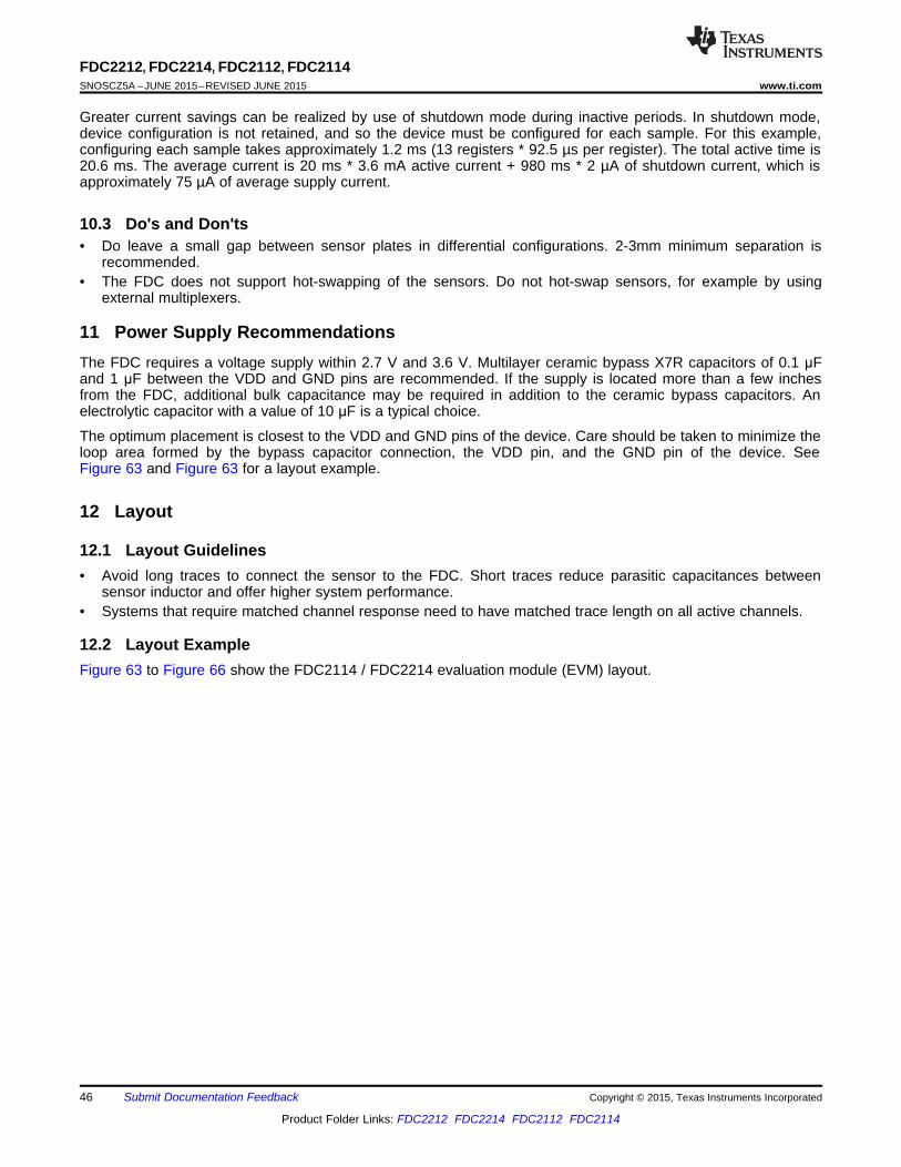
FDC2212, FDC2214, FDC2112, FDC2114SNOSCZ5A –JUNE 2015–REVISED JUNE 2015 www.ti.com
Greater current savings can be realized by use of shutdown mode during inactive periods. In shutdown mode,device configuration is not retained, and so the device must be configured for each sample. For this example,configuring each sample takes approximately 1.2 ms (13 registers * 92.5 µs per register). The total active time is20.6 ms. The average current is 20 ms * 3.6 mA active current + 980 ms * 2 µA of shutdown current, which isapproximately 75 µA of average supply current.
10.3 Do's and Don'ts• Do leave a small gap between sensor plates in differential configurations. 2-3mm minimum separation is
recommended.• The FDC does not support hot-swapping of the sensors. Do not hot-swap sensors, for example by using
external multiplexers.
11 Power Supply RecommendationsThe FDC requires a voltage supply within 2.7 V and 3.6 V. Multilayer ceramic bypass X7R capacitors of 0.1 μFand 1 μF between the VDD and GND pins are recommended. If the supply is located more than a few inchesfrom the FDC, additional bulk capacitance may be required in addition to the ceramic bypass capacitors. Anelectrolytic capacitor with a value of 10 μF is a typical choice.
The optimum placement is closest to the VDD and GND pins of the device. Care should be taken to minimize theloop area formed by the bypass capacitor connection, the VDD pin, and the GND pin of the device. SeeFigure 63 and Figure 63 for a layout example.
12 Layout
12.1 Layout Guidelines• Avoid long traces to connect the sensor to the FDC. Short traces reduce parasitic capacitances between
sensor inductor and offer higher system performance.• Systems that require matched channel response need to have matched trace length on all active channels.
12.2 Layout ExampleFigure 63 to Figure 66 show the FDC2114 / FDC2214 evaluation module (EVM) layout.
46 Submit Documentation Feedback Copyright © 2015, Texas Instruments Incorporated
Product Folder Links: FDC2212 FDC2214 FDC2112 FDC2114

FDC2212, FDC2214, FDC2112, FDC2114www.ti.com SNOSCZ5A –JUNE 2015–REVISED JUNE 2015
Layout Example (continued)
Figure 63. Example PCB Layout: Top Layer (Signal)
Copyright © 2015, Texas Instruments Incorporated Submit Documentation Feedback 47
Product Folder Links: FDC2212 FDC2214 FDC2112 FDC2114

FDC2212, FDC2214, FDC2112, FDC2114SNOSCZ5A –JUNE 2015–REVISED JUNE 2015 www.ti.com
Layout Example (continued)
Figure 64. Example PCB Layout: Mid-layer 1 (GND)
48 Submit Documentation Feedback Copyright © 2015, Texas Instruments Incorporated
Product Folder Links: FDC2212 FDC2214 FDC2112 FDC2114

FDC2212, FDC2214, FDC2112, FDC2114www.ti.com SNOSCZ5A –JUNE 2015–REVISED JUNE 2015
Layout Example (continued)
Figure 65. Example PCB Layout: Mid-layer 2 (Power)
Copyright © 2015, Texas Instruments Incorporated Submit Documentation Feedback 49
Product Folder Links: FDC2212 FDC2214 FDC2112 FDC2114

FDC2212, FDC2214, FDC2112, FDC2114SNOSCZ5A –JUNE 2015–REVISED JUNE 2015 www.ti.com
Layout Example (continued)
Figure 66. Example PCB Layout: Bottom Layer (Signal)
50 Submit Documentation Feedback Copyright © 2015, Texas Instruments Incorporated
Product Folder Links: FDC2212 FDC2214 FDC2112 FDC2114

FDC2212, FDC2214, FDC2112, FDC2114www.ti.com SNOSCZ5A –JUNE 2015–REVISED JUNE 2015
13 Device and Documentation Support
13.1 Device Support
13.1.1 Third-Party Products DisclaimerTI'S PUBLICATION OF INFORMATION REGARDING THIRD-PARTY PRODUCTS OR SERVICES DOES NOTCONSTITUTE AN ENDORSEMENT REGARDING THE SUITABILITY OF SUCH PRODUCTS OR SERVICESOR A WARRANTY, REPRESENTATION OR ENDORSEMENT OF SUCH PRODUCTS OR SERVICES, EITHERALONE OR IN COMBINATION WITH ANY TI PRODUCT OR SERVICE.
13.2 Related LinksTable 48 lists quick access links. Categories include technical documents, support and community resources,tools and software, and quick access to sample or buy.
Table 48. Related LinksTECHNICAL TOOLS & SUPPORT &PARTS PRODUCT FOLDER SAMPLE & BUY DOCUMENTS SOFTWARE COMMUNITY
FDC2212 Click here Click here Click here Click here Click hereFDC2214 Click here Click here Click here Click here Click hereFDC2112 Click here Click here Click here Click here Click hereFDC2114 Click here Click here Click here Click here Click here
13.3 Community ResourcesThe following links connect to TI community resources. Linked contents are provided "AS IS" by the respectivecontributors. They do not constitute TI specifications and do not necessarily reflect TI's views; see TI's Terms ofUse.
TI E2E™ Online Community TI's Engineer-to-Engineer (E2E) Community. Created to foster collaborationamong engineers. At e2e.ti.com, you can ask questions, share knowledge, explore ideas and helpsolve problems with fellow engineers.
Design Support TI's Design Support Quickly find helpful E2E forums along with design support tools andcontact information for technical support.
13.4 TrademarksE2E is a trademark of Texas Instruments.All other trademarks are the property of their respective owners.
13.5 Electrostatic Discharge CautionThese devices have limited built-in ESD protection. The leads should be shorted together or the device placed in conductive foamduring storage or handling to prevent electrostatic damage to the MOS gates.
13.6 GlossarySLYZ022 — TI Glossary.
This glossary lists and explains terms, acronyms, and definitions.
14 Mechanical, Packaging, and Orderable InformationThe following pages include mechanical, packaging, and orderable information. This information is the mostcurrent data available for the designated devices. This data is subject to change without notice and revision ofthis document. For browser-based versions of this data sheet, refer to the left-hand navigation.
Copyright © 2015, Texas Instruments Incorporated Submit Documentation Feedback 51
Product Folder Links: FDC2212 FDC2214 FDC2112 FDC2114

PACKAGE OPTION ADDENDUM
www.ti.com 26-Jun-2016
Addendum-Page 1
PACKAGING INFORMATION
Orderable Device Status(1)
Package Type PackageDrawing
Pins PackageQty
Eco Plan(2)
Lead/Ball Finish(6)
MSL Peak Temp(3)
Op Temp (°C) Device Marking(4/5)
Samples
FDC2112DNTR ACTIVE WSON DNT 12 4500 Green (RoHS& no Sb/Br)
CU SN Level-1-260C-UNLIM -40 to 125 FDC2112
FDC2112DNTT ACTIVE WSON DNT 12 250 Green (RoHS& no Sb/Br)
CU SN Level-1-260C-UNLIM -40 to 125 FDC2112
FDC2112QDNTRQ1 ACTIVE WSON DNT 12 4500 Green (RoHS& no Sb/Br)
CU SN Level-3-260C-168 HR -40 to 125 FDC2112Q1
FDC2112QDNTTQ1 ACTIVE WSON DNT 12 250 Green (RoHS& no Sb/Br)
CU SN Level-3-260C-168 HR -40 to 125 FDC2112Q1
FDC2114QRGHRQ1 ACTIVE WQFN RGH 16 4500 Green (RoHS& no Sb/Br)
CU SN Level-3-260C-168 HR -40 to 125 FC2114Q
FDC2114QRGHTQ1 ACTIVE WQFN RGH 16 250 Green (RoHS& no Sb/Br)
CU SN Level-3-260C-168 HR -40 to 125 FC2114Q
FDC2114RGHR ACTIVE WQFN RGH 16 4500 Green (RoHS& no Sb/Br)
CU SN Level-1-260C-UNLIM -40 to 125 FDC2114
FDC2114RGHT ACTIVE WQFN RGH 16 250 Green (RoHS& no Sb/Br)
CU SN Level-1-260C-UNLIM -40 to 125 FDC2114
FDC2212DNTR ACTIVE WSON DNT 12 4500 Green (RoHS& no Sb/Br)
CU SN Level-1-260C-UNLIM -40 to 125 FDC2212
FDC2212DNTT ACTIVE WSON DNT 12 250 Green (RoHS& no Sb/Br)
CU SN Level-1-260C-UNLIM -40 to 125 FDC2212
FDC2212QDNTRQ1 ACTIVE WSON DNT 12 4500 Green (RoHS& no Sb/Br)
CU SN Level-3-260C-168 HR -40 to 125 FDC2212Q1
FDC2212QDNTTQ1 ACTIVE WSON DNT 12 250 Green (RoHS& no Sb/Br)
CU SN Level-3-260C-168 HR -40 to 125 FDC2212Q1
FDC2214QRGHRQ1 ACTIVE WQFN RGH 16 4500 Green (RoHS& no Sb/Br)
CU SN Level-3-260C-168 HR -40 to 125 FC2214Q
FDC2214QRGHTQ1 ACTIVE WQFN RGH 16 250 Green (RoHS& no Sb/Br)
CU SN Level-3-260C-168 HR -40 to 125 FC2214Q
FDC2214RGHR ACTIVE WQFN RGH 16 4500 Green (RoHS& no Sb/Br)
CU SN Level-1-260C-UNLIM -40 to 125 FDC2214
FDC2214RGHT ACTIVE WQFN RGH 16 250 Green (RoHS& no Sb/Br)
CU SN Level-1-260C-UNLIM -40 to 125 FDC2214
(1) The marketing status values are defined as follows:ACTIVE: Product device recommended for new designs.

PACKAGE OPTION ADDENDUM
www.ti.com 26-Jun-2016
Addendum-Page 2
LIFEBUY: TI has announced that the device will be discontinued, and a lifetime-buy period is in effect.NRND: Not recommended for new designs. Device is in production to support existing customers, but TI does not recommend using this part in a new design.PREVIEW: Device has been announced but is not in production. Samples may or may not be available.OBSOLETE: TI has discontinued the production of the device.
(2) Eco Plan - The planned eco-friendly classification: Pb-Free (RoHS), Pb-Free (RoHS Exempt), or Green (RoHS & no Sb/Br) - please check http://www.ti.com/productcontent for the latest availabilityinformation and additional product content details.TBD: The Pb-Free/Green conversion plan has not been defined.Pb-Free (RoHS): TI's terms "Lead-Free" or "Pb-Free" mean semiconductor products that are compatible with the current RoHS requirements for all 6 substances, including the requirement thatlead not exceed 0.1% by weight in homogeneous materials. Where designed to be soldered at high temperatures, TI Pb-Free products are suitable for use in specified lead-free processes.Pb-Free (RoHS Exempt): This component has a RoHS exemption for either 1) lead-based flip-chip solder bumps used between the die and package, or 2) lead-based die adhesive used betweenthe die and leadframe. The component is otherwise considered Pb-Free (RoHS compatible) as defined above.Green (RoHS & no Sb/Br): TI defines "Green" to mean Pb-Free (RoHS compatible), and free of Bromine (Br) and Antimony (Sb) based flame retardants (Br or Sb do not exceed 0.1% by weightin homogeneous material)
(3) MSL, Peak Temp. - The Moisture Sensitivity Level rating according to the JEDEC industry standard classifications, and peak solder temperature.
(4) There may be additional marking, which relates to the logo, the lot trace code information, or the environmental category on the device.
(5) Multiple Device Markings will be inside parentheses. Only one Device Marking contained in parentheses and separated by a "~" will appear on a device. If a line is indented then it is a continuationof the previous line and the two combined represent the entire Device Marking for that device.
(6) Lead/Ball Finish - Orderable Devices may have multiple material finish options. Finish options are separated by a vertical ruled line. Lead/Ball Finish values may wrap to two lines if the finishvalue exceeds the maximum column width.
Important Information and Disclaimer:The information provided on this page represents TI's knowledge and belief as of the date that it is provided. TI bases its knowledge and belief on informationprovided by third parties, and makes no representation or warranty as to the accuracy of such information. Efforts are underway to better integrate information from third parties. TI has taken andcontinues to take reasonable steps to provide representative and accurate information but may not have conducted destructive testing or chemical analysis on incoming materials and chemicals.TI and TI suppliers consider certain information to be proprietary, and thus CAS numbers and other limited information may not be available for release.
In no event shall TI's liability arising out of such information exceed the total purchase price of the TI part(s) at issue in this document sold by TI to Customer on an annual basis.
OTHER QUALIFIED VERSIONS OF FDC2112, FDC2112-Q1, FDC2114, FDC2114-Q1, FDC2212, FDC2212-Q1, FDC2214, FDC2214-Q1 :
• Catalog: FDC2112, FDC2114, FDC2212, FDC2214
• Automotive: FDC2112-Q1, FDC2114-Q1, FDC2212-Q1, FDC2214-Q1
NOTE: Qualified Version Definitions:

PACKAGE OPTION ADDENDUM
www.ti.com 26-Jun-2016
Addendum-Page 3
• Catalog - TI's standard catalog product
• Automotive - Q100 devices qualified for high-reliability automotive applications targeting zero defects

TAPE AND REEL INFORMATION
*All dimensions are nominal
Device PackageType
PackageDrawing
Pins SPQ ReelDiameter
(mm)
ReelWidth
W1 (mm)
A0(mm)
B0(mm)
K0(mm)
P1(mm)
W(mm)
Pin1Quadrant
FDC2112DNTR WSON DNT 12 4500 330.0 12.4 4.3 4.3 1.3 8.0 12.0 Q1
FDC2112DNTT WSON DNT 12 250 178.0 12.4 4.3 4.3 1.3 8.0 12.0 Q1
FDC2112QDNTRQ1 WSON DNT 12 4500 330.0 12.4 4.3 4.3 1.3 8.0 12.0 Q1
FDC2112QDNTTQ1 WSON DNT 12 250 178.0 12.4 4.3 4.3 1.3 8.0 12.0 Q1
FDC2114QRGHRQ1 WQFN RGH 16 4500 330.0 12.4 4.3 4.3 1.3 8.0 12.0 Q1
FDC2114QRGHTQ1 WQFN RGH 16 250 178.0 12.4 4.3 4.3 1.3 8.0 12.0 Q1
FDC2114RGHR WQFN RGH 16 4500 330.0 12.4 4.3 4.3 1.3 8.0 12.0 Q1
FDC2114RGHT WQFN RGH 16 250 178.0 12.4 4.3 4.3 1.3 8.0 12.0 Q1
FDC2212DNTR WSON DNT 12 4500 330.0 12.4 4.3 4.3 1.3 8.0 12.0 Q1
FDC2212DNTT WSON DNT 12 250 178.0 12.4 4.3 4.3 1.3 8.0 12.0 Q1
FDC2212QDNTRQ1 WSON DNT 12 4500 330.0 12.4 4.3 4.3 1.3 8.0 12.0 Q1
FDC2212QDNTTQ1 WSON DNT 12 250 178.0 12.4 4.3 4.3 1.3 8.0 12.0 Q1
FDC2214QRGHRQ1 WQFN RGH 16 4500 330.0 12.4 4.3 4.3 1.3 8.0 12.0 Q1
FDC2214QRGHTQ1 WQFN RGH 16 250 178.0 12.4 4.3 4.3 1.3 8.0 12.0 Q1
FDC2214RGHR WQFN RGH 16 4500 330.0 12.4 4.3 4.3 1.3 8.0 12.0 Q1
FDC2214RGHT WQFN RGH 16 250 178.0 12.4 4.3 4.3 1.3 8.0 12.0 Q1
PACKAGE MATERIALS INFORMATION
www.ti.com 20-Sep-2016
Pack Materials-Page 1

*All dimensions are nominal
Device Package Type Package Drawing Pins SPQ Length (mm) Width (mm) Height (mm)
FDC2112DNTR WSON DNT 12 4500 367.0 367.0 35.0
FDC2112DNTT WSON DNT 12 250 210.0 185.0 35.0
FDC2112QDNTRQ1 WSON DNT 12 4500 367.0 367.0 35.0
FDC2112QDNTTQ1 WSON DNT 12 250 210.0 185.0 35.0
FDC2114QRGHRQ1 WQFN RGH 16 4500 367.0 367.0 35.0
FDC2114QRGHTQ1 WQFN RGH 16 250 210.0 185.0 35.0
FDC2114RGHR WQFN RGH 16 4500 367.0 367.0 35.0
FDC2114RGHT WQFN RGH 16 250 210.0 185.0 35.0
FDC2212DNTR WSON DNT 12 4500 367.0 367.0 35.0
FDC2212DNTT WSON DNT 12 250 210.0 185.0 35.0
FDC2212QDNTRQ1 WSON DNT 12 4500 367.0 367.0 35.0
FDC2212QDNTTQ1 WSON DNT 12 250 210.0 185.0 35.0
FDC2214QRGHRQ1 WQFN RGH 16 4500 367.0 367.0 35.0
FDC2214QRGHTQ1 WQFN RGH 16 250 210.0 185.0 35.0
FDC2214RGHR WQFN RGH 16 4500 367.0 367.0 35.0
FDC2214RGHT WQFN RGH 16 250 210.0 185.0 35.0
PACKAGE MATERIALS INFORMATION
www.ti.com 20-Sep-2016
Pack Materials-Page 2

DNT0012B WSON - 0.8mm max height
SON (PLASTIC SMALL OUTLINE - NO LEAD)
www.ti.com
MECHANICAL DATA
4214928/A 03/2013
SDA12B (Rev A)
1. All linear dimensions are in millimeters. Dimensions in parenthesis are for reference only. Dimensioning and tolerancing per ASME Y14.5M. 2. This drawing is subject to change without notice. 3. This package is designed to be soldered to a thermal pad on the board for thermal and mechanical performance. For more information, refer to QFN/SON PCB application note in literature No. SLUA271 (www.ti.com/lit/slua271).
NOTES:

www.ti.com
PACKAGE OUTLINE
C
SEE TERMINALDETAIL
16X 0.30.2
2.6 0.1
16X 0.50.3
0.8 MAX
(A) TYP
0.050.00
12X 0.5
4X1.5
B 4.13.9
A
4.13.9
0.30.2
0.50.3
WQFN - 0.8 mm max heightRGH0016APLASTIC QUAD FLATPACK - NO LEAD
4214978/B 01/2017
DIM A OPT 1 OPT 1(0.1) (0.2)
PIN 1 INDEX AREA
0.08
SEATING PLANE
1
49
12
5 8
16 13(OPTIONAL)
PIN 1 ID
0.1 C A B0.05
EXPOSEDTHERMAL PAD
17 SYMM
SYMM
NOTES: 1. All linear dimensions are in millimeters. Any dimensions in parenthesis are for reference only. Dimensioning and tolerancing per ASME Y14.5M. 2. This drawing is subject to change without notice. 3. The package thermal pad must be soldered to the printed circuit board for optimal thermal and mechanical performance.
SCALE 3.000
DETAILOPTIONAL TERMINAL
TYPICAL

www.ti.com
EXAMPLE BOARD LAYOUT
0.07 MINALL AROUND
0.07 MAXALL AROUND
16X (0.25)
16X (0.6)
( 0.2) TYPVIA
12X (0.5)
(3.8)
(3.8)
(1)
( 2.6)
(R0.05)TYP
(1)
WQFN - 0.8 mm max heightRGH0016APLASTIC QUAD FLATPACK - NO LEAD
4214978/B 01/2017
SYMM
1
4
5 8
9
12
1316
SYMM
LAND PATTERN EXAMPLEEXPOSED METAL SHOWN
SCALE:15X
17
NOTES: (continued) 4. This package is designed to be soldered to a thermal pad on the board. For more information, see Texas Instruments literature number SLUA271 (www.ti.com/lit/slua271).5. Vias are optional depending on application, refer to device data sheet. If any vias are implemented, refer to their locations shown on this view. It is recommended that vias under paste be filled, plugged or tented.
SOLDER MASKOPENING
METAL UNDERSOLDER MASK
SOLDER MASKDEFINED
EXPOSED METALMETAL
SOLDER MASKOPENING
SOLDER MASK DETAILS
NON SOLDER MASKDEFINED
(PREFERRED)
EXPOSED METAL

www.ti.com
EXAMPLE STENCIL DESIGN
16X (0.6)
16X (0.25)
12X (0.5)
(3.8)
(3.8)
4X ( 1.15)
(0.675)TYP
(0.675) TYP
(R0.05)TYP
WQFN - 0.8 mm max heightRGH0016APLASTIC QUAD FLATPACK - NO LEAD
4214978/B 01/2017
NOTES: (continued) 6. Laser cutting apertures with trapezoidal walls and rounded corners may offer better paste release. IPC-7525 may have alternate design recommendations.
SYMM
TYPEXPOSED METAL
SOLDER PASTE EXAMPLEBASED ON 0.125 mm THICK STENCIL
EXPOSED PAD 17
78% PRINTED SOLDER COVERAGE BY AREA UNDER PACKAGESCALE:20X
SYMM
1
4
5 8
9
12
1316
17

IMPORTANT NOTICE
Texas Instruments Incorporated (TI) reserves the right to make corrections, enhancements, improvements and other changes to itssemiconductor products and services per JESD46, latest issue, and to discontinue any product or service per JESD48, latest issue. Buyersshould obtain the latest relevant information before placing orders and should verify that such information is current and complete.TI’s published terms of sale for semiconductor products (http://www.ti.com/sc/docs/stdterms.htm) apply to the sale of packaged integratedcircuit products that TI has qualified and released to market. Additional terms may apply to the use or sale of other types of TI products andservices.Reproduction of significant portions of TI information in TI data sheets is permissible only if reproduction is without alteration and isaccompanied by all associated warranties, conditions, limitations, and notices. TI is not responsible or liable for such reproduceddocumentation. Information of third parties may be subject to additional restrictions. Resale of TI products or services with statementsdifferent from or beyond the parameters stated by TI for that product or service voids all express and any implied warranties for theassociated TI product or service and is an unfair and deceptive business practice. TI is not responsible or liable for any such statements.Buyers and others who are developing systems that incorporate TI products (collectively, “Designers”) understand and agree that Designersremain responsible for using their independent analysis, evaluation and judgment in designing their applications and that Designers havefull and exclusive responsibility to assure the safety of Designers' applications and compliance of their applications (and of all TI productsused in or for Designers’ applications) with all applicable regulations, laws and other applicable requirements. Designer represents that, withrespect to their applications, Designer has all the necessary expertise to create and implement safeguards that (1) anticipate dangerousconsequences of failures, (2) monitor failures and their consequences, and (3) lessen the likelihood of failures that might cause harm andtake appropriate actions. Designer agrees that prior to using or distributing any applications that include TI products, Designer willthoroughly test such applications and the functionality of such TI products as used in such applications.TI’s provision of technical, application or other design advice, quality characterization, reliability data or other services or information,including, but not limited to, reference designs and materials relating to evaluation modules, (collectively, “TI Resources”) are intended toassist designers who are developing applications that incorporate TI products; by downloading, accessing or using TI Resources in anyway, Designer (individually or, if Designer is acting on behalf of a company, Designer’s company) agrees to use any particular TI Resourcesolely for this purpose and subject to the terms of this Notice.TI’s provision of TI Resources does not expand or otherwise alter TI’s applicable published warranties or warranty disclaimers for TIproducts, and no additional obligations or liabilities arise from TI providing such TI Resources. TI reserves the right to make corrections,enhancements, improvements and other changes to its TI Resources. TI has not conducted any testing other than that specificallydescribed in the published documentation for a particular TI Resource.Designer is authorized to use, copy and modify any individual TI Resource only in connection with the development of applications thatinclude the TI product(s) identified in such TI Resource. NO OTHER LICENSE, EXPRESS OR IMPLIED, BY ESTOPPEL OR OTHERWISETO ANY OTHER TI INTELLECTUAL PROPERTY RIGHT, AND NO LICENSE TO ANY TECHNOLOGY OR INTELLECTUAL PROPERTYRIGHT OF TI OR ANY THIRD PARTY IS GRANTED HEREIN, including but not limited to any patent right, copyright, mask work right, orother intellectual property right relating to any combination, machine, or process in which TI products or services are used. Informationregarding or referencing third-party products or services does not constitute a license to use such products or services, or a warranty orendorsement thereof. Use of TI Resources may require a license from a third party under the patents or other intellectual property of thethird party, or a license from TI under the patents or other intellectual property of TI.TI RESOURCES ARE PROVIDED “AS IS” AND WITH ALL FAULTS. TI DISCLAIMS ALL OTHER WARRANTIES ORREPRESENTATIONS, EXPRESS OR IMPLIED, REGARDING RESOURCES OR USE THEREOF, INCLUDING BUT NOT LIMITED TOACCURACY OR COMPLETENESS, TITLE, ANY EPIDEMIC FAILURE WARRANTY AND ANY IMPLIED WARRANTIES OFMERCHANTABILITY, FITNESS FOR A PARTICULAR PURPOSE, AND NON-INFRINGEMENT OF ANY THIRD PARTY INTELLECTUALPROPERTY RIGHTS. TI SHALL NOT BE LIABLE FOR AND SHALL NOT DEFEND OR INDEMNIFY DESIGNER AGAINST ANY CLAIM,INCLUDING BUT NOT LIMITED TO ANY INFRINGEMENT CLAIM THAT RELATES TO OR IS BASED ON ANY COMBINATION OFPRODUCTS EVEN IF DESCRIBED IN TI RESOURCES OR OTHERWISE. IN NO EVENT SHALL TI BE LIABLE FOR ANY ACTUAL,DIRECT, SPECIAL, COLLATERAL, INDIRECT, PUNITIVE, INCIDENTAL, CONSEQUENTIAL OR EXEMPLARY DAMAGES INCONNECTION WITH OR ARISING OUT OF TI RESOURCES OR USE THEREOF, AND REGARDLESS OF WHETHER TI HAS BEENADVISED OF THE POSSIBILITY OF SUCH DAMAGES.Unless TI has explicitly designated an individual product as meeting the requirements of a particular industry standard (e.g., ISO/TS 16949and ISO 26262), TI is not responsible for any failure to meet such industry standard requirements.Where TI specifically promotes products as facilitating functional safety or as compliant with industry functional safety standards, suchproducts are intended to help enable customers to design and create their own applications that meet applicable functional safety standardsand requirements. Using products in an application does not by itself establish any safety features in the application. Designers mustensure compliance with safety-related requirements and standards applicable to their applications. Designer may not use any TI products inlife-critical medical equipment unless authorized officers of the parties have executed a special contract specifically governing such use.Life-critical medical equipment is medical equipment where failure of such equipment would cause serious bodily injury or death (e.g., lifesupport, pacemakers, defibrillators, heart pumps, neurostimulators, and implantables). Such equipment includes, without limitation, allmedical devices identified by the U.S. Food and Drug Administration as Class III devices and equivalent classifications outside the U.S.TI may expressly designate certain products as completing a particular qualification (e.g., Q100, Military Grade, or Enhanced Product).Designers agree that it has the necessary expertise to select the product with the appropriate qualification designation for their applicationsand that proper product selection is at Designers’ own risk. Designers are solely responsible for compliance with all legal and regulatoryrequirements in connection with such selection.Designer will fully indemnify TI and its representatives against any damages, costs, losses, and/or liabilities arising out of Designer’s non-compliance with the terms and provisions of this Notice.
Mailing Address: Texas Instruments, Post Office Box 655303, Dallas, Texas 75265Copyright © 2017, Texas Instruments Incorporated