Embed Size (px)
Citation preview
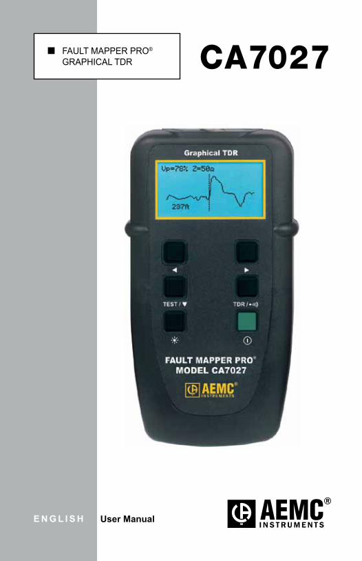
CA7027 FAULT MAPPER PRO®
GRAPHICAL TDR
E N G L I S H User Manual

Statement of Compliance
Chauvin Arnoux®, Inc. d.b.a. AEMC® Instruments certifies that this instrument has been calibrated using standards and instruments traceable to international standards.
We guarantee that at the time of shipping your instrument has met its published specifications.
The recommended calibration interval for this instrument is 12 months and begins on the date of receipt by the customer. For recalibration, please use our calibration services. Refer to our repair and calibration section at www.aemc.com.
Serial #: ________________________________
Catalog #: 2127.84
Model #: CA7027
Please fill in the appropriate date as indicated:
Date Received: _________________________________
Date Calibration Due: _______________________
Chauvin Arnoux®, Inc.d.b.a AEMC® Instrumentswww.aemc.com

Table of Contents
1. INTRODUCTION ............................................................................... 21.1 International Electrical Symbols ................................................21.2 Receiving Your Shipment ..........................................................31.3 Ordering Information .................................................................3
1.3.1 Accessories and Replacement Parts ............................3
2. PRODUCT FEATURES ...................................................................... 42.1 Description ................................................................................42.2 Key Features: ...........................................................................42.3 Fault Mapper Pro® Features .....................................................5
3. SPECIFICATIONS............................................................................. 63.1 Accuracy ...................................................................................7
4. OPERATION .................................................................................... 84.1 Principles of Operation .............................................................84.2 Accuracy and Velocity of Propagation (Vp) ..............................84.3 Getting Started ..........................................................................94.4 Set-up Mode .............................................................................94.5 Backlight .................................................................................104.6 Tone Generator .......................................................................104.7 Selecting Full Scale Sensitivity ...............................................114.8 Adjusting the Vp Value ............................................................114.9 Determining and Measuring Vp Values ..................................114.10 Attaching a Cable to the Fault Mapper Pro® ...........................124.11 Testing a Cable .......................................................................134.12 Single Shot and Continuous Scanning Modes .......................144.13 Typical Fault Displays .............................................................14
5. MAINTENANCE ............................................................................. 155.1 Changing the Battery ..............................................................155.2 Cleaning ..................................................................................155.3 Storage ...................................................................................15
Repair and Calibration ...........................................................................16Technical and Sales Assistance ............................................................16Limited Warranty ...................................................................................17Warranty Repairs ...................................................................................17
2 Fault Mapper Pro® Model CA7027
CHAPTER 1
INTRODUCTION
Warning
This instrument meets the safety requirements of IEC61010-1:1995.
TheModelCA7027isdesignedforuseonde-energizedcircuitsonly.
Connection to line voltages will damage the instrument andcouldbehazardoustotheoperator.
This instrument is protected against connection to telecomnetworkvoltagesaccordingtoEN61326-1.
Safetyistheresponsibilityoftheoperator.
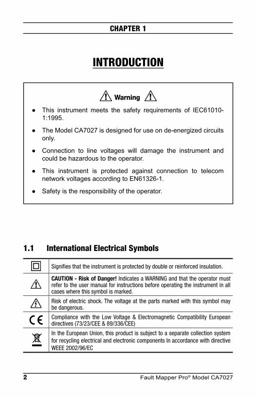
1.1 International Electrical Symbols
Signifies that the instrument is protected by double or reinforced insulation.
CAUTION - Risk of Danger! Indicates a WARNING and that the operator must refer to the user manual for instructions before operating the instrument in all cases where this symbol is marked.
Risk of electric shock. The voltage at the parts marked with this symbol may be dangerous.
Compliance with the Low Voltage & Electromagnetic Compatibility European directives (73/23/CEE & 89/336/CEE)
In the European Union, this product is subject to a separate collection system for recycling electrical and electronic components In accordance with directive WEEE 2002/96/EC
Fault Mapper Pro® Model CA7027 3
1.2 Receiving Your ShipmentUpon receiving your shipment, make sure that the contents are consis-tentwith thepacking list.Notifyyourdistributorofanymissing items. Iftheequipmentappearstobedamaged,fileaclaimimmediatelywiththecarrier and notify your distributor at once, giving a detailed description of any damage. Save the damaged packing container to substantiate your claim.
1.3 Ordering InformationFault Mapper Pro® Model CA7027 ....................................Cat. #2127.84Includes carrying case, 4mm color-coded banana plugs with alligator clips, 4x1.5V AA batteries, set of 2 color-coded 4 ft red/black leads, user manual and product warranty card.
1.3.1 Accessories and Replacement PartsLead - Replacement set of 2, Color-coded 4 ft (Red/Black), Test Probes & Alligator Clips ...............................................Cat. #2152.01

4 Fault Mapper Pro® Model CA7027
CHAPTER 2
PRODUCT FEATURES
2.1 DescriptionThe Fault Mapper Pro® is a hand-held graphical TDR (Time Domain Reflectometer)designedforidentifyingandlocatingfaultsonpowerandcommunication cables, given access to one end only.The Fault Mapper Pro® measures cable length and indicates the length and distance to cable faults to a range of 9 ft (3 m) to 19,000 ft (6000m) on virtually any type of cable. It injects a series of pulses into the cable under test.Thevelocityatwhichthepulsestravelisdeterminedbythetypeofcable,whichisknownasthevelocityofpropagation(Vp)ofthecable.TheVelocityofPropagation(Vp)isadjustablebetween1%and99%enablingaccurate calibration to the cable under test.The Vp value is expressed as a percentage of the speed of light (e.g. 67%or ft/mtrs/micro-second), this valuewill vary according to the typeof cable under test. The Fault Mapper Pro® can accept user selectable valuesbetween1and99%(ortheequivalentvalueinfeetormeterspermicro-second).Based on the selected Vp and the time taken for the pulses to travel throughthecable,areflectionprofileofthecableundertestisdisplayed.An adjustable cursor assists in locating faults and termination.The Fault Mapper Pro® incorporatesanoscillating tone tracer,which isdetectablewithastandardtonetracer,foruseinthetracingandidentifica-tion of cable pairs.
2.2 Key Features: Hand-heldgraphicalTDR(TimeDomainReflectometer) Measures cable length and indicates distance to faults to a range of
19,000 ft (6000m) Graphical LCD Easyidentificationofshortrangefaults Emits an audible tone, used to trace and identify the type of fault
Fault Mapper Pro® Model CA7027 5
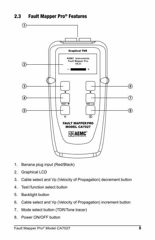
2.3 Fault Mapper Pro® Features
2
3
4
5
6
7
8
FAULT MAPPER PROMODEL CA7027
TEST / TDR /
Graphical TDR
AEMC InstrumentsFault Mapper Pro
VX.X
1
1. Banana plug input (Red/Black)
2. Graphical LCD
3. Cable select and Vp (Velocity of Propagation) decrement button
4. Test/ function select button
5. Backlight button
6. Cable select and Vp (Velocity of Propagation) increment button
7. Mode select button (TDR/Tone tracer)
8. PowerON/OFFbutton
6 Fault Mapper Pro® Model CA7027
CHAPTER 3
SPECIFICATIONS
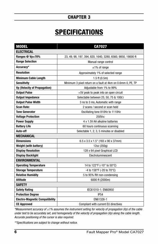
MODEL CA7027ELECTRICALRanges @ Vp=70% 23, 49, 98, 197, 394, 820, 1640, 3280, 6560, 9850, 19000 ft
Range Selection Manual range control
Accuracy* ±1% of range
Resolution Approximately 1% of selected range
Minimum Cable Length 1.5 ft (0.5m)
Sensitivity Minimum 3 pixel return on a fault at 4km on 0.6mm 0, PE, TP
Vp (Velocity of Propagation) Adjustable from 1% to 99%
Output Pulse +5V peak to peak into an open circuit
Output Impedance Selectable between 25, 50, 75 & 100ΩOutput Pulse Width 3 ns to 3 ms, Automatic with range
Scan Rate: 2 scans / second or scan held
Tone Generator Oscillating tone 810Hz to 1110Hz
Voltage Protection 250VAC
Power Supply 4 x 1.5V AA alkaline batteries
Battery Life 60 hours continuous scanning
Auto-off Selectable 1, 2, 3, 5 minutes or disabled
MECHANICALDimensions 6.5 x 3.5 x 1.5" (165 x 90 x 37mm)
Weight (with battery) 12oz (350g)
Display Resolution 128 x 64 pixel Graphical LCD
Display Backlight Electroluminescent
ENVIRONMENTALOperating Temperature 14 to 122°F (-10° to 50°C)
Storage Temperature -4 to 158°F (-20 to 70°C)
Relative Humidity 5 to 95% RH non-condensing
Altitude 6000 ft (2000m)
SAFETYSafety Rating IEC61010-1; EN60950
Protection Degree IP54
Electro-Magnetic Compatibility EN61326-1
CE Approved Compliant with current EU directives
*Measurement accuracy of ±1% assumes the instrument setting for velocity of propagation (Vp) of the cable under test to be accurately set, and homogeneity of the velocity of propagation (Vp) along the cable length. Accurate positioning of the cursor is also required.
**Specifications are subject to change without notice.
Fault Mapper Pro® Model CA7027 7
3.1 AccuracyThe CA7027 is able to measure distances to faults and cable lengths to anaccuracyof±1%.This measurement accuracy is based on the correct value of Vp being used for the cable under test, and homogeneity of the Vp along the cable length.If the Vp is set incorrectly by the operator, or the Vp varies along the length ofthecable,thenadditionalerrorswillbeincurredandthemeasurementaccuracywillbeaffected.NOTE:TheVpislesswelldefinedwithunshieldedmulticorecable,includ-ingpowercable,andislowerwhenacableistightlywoundonadrumthanwheninstalled.
8 Fault Mapper Pro® Model CA7027
CHAPTER 4
OPERATION
4.1 Principles of OperationThe Fault Mapper Pro®worksbymeasuringthetimetakenforasignaltotravel to the far end of the cable under test, or to an intermediate fault and return.ThevelocityatwhichthesignaltravelsVp(VelocityofPropagation)willdependonthecharacteristicsofthecable.Based on the selected Vp and the measured travel time of the test pulse, the Fault Mapper Pro® calculates and displays impedance anomalies and their distances along the cable.
4.2 Accuracy and Velocity of Propagation (Vp)The Fault Mapper Pro® measures distances to faults and cable lengths to anaccuracyof±1%.Thismeasurementaccuracyisbaseduponthecor-rect value of Vp being used for the cable under test, and homogeneity of the Vp along the cable length.If the Vp is set incorrectly by the operator, or the Vp varies along the length ofthecable,thenadditionalerrorswillbeincurredandthemeasurementaccuracywillbeaffected.
See § 4.8 for setting the Vp.
NOTE: The Vp is less well defined with unshielded multi-conductor cable, including power cable, and is lower when a cable is tightly wound on a drum than when it is installed in a linear fashion.
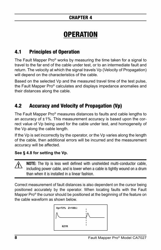
Correct measurement of fault distances is also dependent on the cursor being positioned accurately by the operator. When locating faults with the FaultMapper Pro® the cursor should be positioned at the beginning of the feature on thecablewaveformasshownbelow.
Vp=72% Z=100Ω
621ft

Fault Mapper Pro® Model CA7027 9
4.3 Getting StartedThe instrument is switched on and off using the green power button , foundonthelowerrightsideofthefrontpanel.Whentheunitisfirstswitchedonitwilldisplaytheopeningscreengivingthesoftwareversion,thecurrentlyselected Vp (Velocity of Propagation), cable impedance and battery status indicator.
AEMC InstrumentsFault Mapper Pro
VX.X
4.4 Set-up Mode
1. HolddowntheTDR / button, then press the TEST / button to enterset-up mode.
TDRVp % VCVp=67%T/P 100ΩMetersContrastShutdown : 1 Minute
>
2. Thefollowingoptionscanbeconfigured:• TDR or Tone Generation• SetVpto%(1to99%)orspeedinmicro-seconds(see§4.8)• Set cable impedance (Z) to 25, 50, 75 or 100Ω Twistedpair(T/P)• Set measurement units to Feet or Meters• Adjust the display contrast• Disable/Enable Auto-off function
3. Press the TEST / button to move the line selector (>)downthescreen.4. Press the and buttons to change the setting of the line selected.5. Press the TDR / button again to save changes and exit set-up mode.
NOTE:WhentheFaultMapperPro®isturnedoff,itwillretainthecurrent set-up parameters.
10 Fault Mapper Pro® Model CA7027
Uponcompletionofconfiguringtheinstrument,atestscreenwillappeardisplayingthefollowinginformation:
• Vp Setting• Impedance setting (Z)• Range scale 7 meters• Battery condition indicator• Distance of cursor• Cursor• Output pulse• Scan mode icon (indicating scan mode selected)
4.5 BacklightTheLCDdisplayisfittedwithanelectroluminescentbacklighttoenableeasyviewingunderavarietyofdifferentlightingconditions.Thebacklightisswitchedonandoffwiththe button.
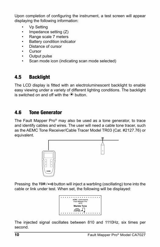
4.6 Tone GeneratorThe Fault Mapper Pro® may also be used as a tone generator, to trace andidentifycablesandwires.Theuserwillneedacabletonetracer,suchas the AEMC Tone Receiver/Cable Tracer Model TR03 (Cat. #2127.76) or equivalent.
Pressing the TDR / buttonwillinjectawarbling(oscillating)toneintothecableorlinkundertest.Whenset,thefollowingwillbedisplayed:
* * * * * * * * * * * * * * * * * * *
* * * * * * * * * * * * * * * * * * *
Warble Tone
AEMC InstrumentsFault Mapper Pro
VX.X
The injected signal oscillates between 810 and 1110Hz, six times persecond.
Fault Mapper Pro® Model CA7027 11
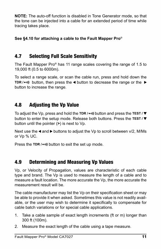
NOTE: The auto-off function is disabled in Tone Generator mode, so that thetonecanbeinjectedintoacableforanextendedperiodoftimewhiletracing takes place.
See §4.10 for attaching a cable to the Fault Mapper Pro®
4.7 Selecting Full Scale SensitivityThe Fault Mapper Pro® has 11 range scales covering the range of 1.5 to 19,000 ft (0.5 to 6000m).
Toselectarangescale,orscanthecablerun,pressandholddowntheTDR / button, then press the button to decrease the range or the button to increase the range.
4.8 Adjusting the Vp Value
To adjust the Vp, press and hold the TDR / button and press the TEST / button to enter the setup mode. Release both buttons. Press the TEST / button until the pointer (>) is next to Vp.
Nextusethe and buttonstoadjusttheVptoscrollbetweenv/2,M/MsorVp%UC.
Press the TDR / button to exit the set up mode.
4.9 Determining and Measuring Vp ValuesVp, or Velocity of Propagation, values are characteristic of each cable type and brand. The Vp is used to measure the length of a cable and to measure a fault location. The more accurate the Vp, the more accurate the measurementresultwillbe.
ThecablemanufacturermaylisttheVpontheirspecificationsheetormaybeabletoprovideitwhenasked.Sometimesthisvalueisnotreadilyavail-able,ortheusermaywishtodetermineitspecificallytocompensateforcable batch variations or for special cable applications.
1. Take a cable sample of exact length increments (ft or m) longer than 300 ft (100m).
2. Measure the exact length of the cable using a tape measure.
12 Fault Mapper Pro® Model CA7027
3. Connect one end of the cable to the Fault Mapper Pro®. Leave the end unterminatedandmakesurethewiresdonotshorttoeachother.
4. Measure the length and adjust the Vp until the exact length is displayed.5. When the exact length is displayed, Vp is established.
4.10 Attaching a Cable to the Fault Mapper Pro®
WARNING: Make sure that there is no power supply or equipment attached to the cable to be tested.
1. Checkthatthefarendofthecableiseitheropenorshorted(notfittedwitharesistivetermination).
2. Attach the Fault Mapper Pro® to one end of the cable to be tested.
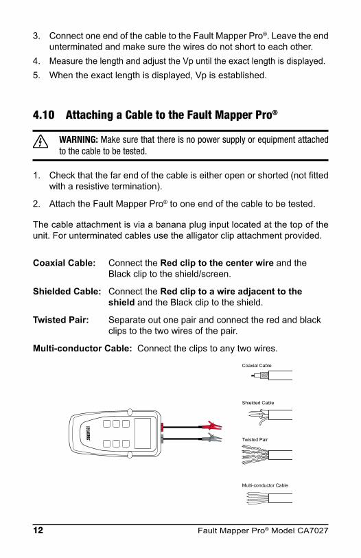
The cable attachment is via a banana plug input located at the top of the unit. For unterminated cables use the alligator clip attachment provided.
Coaxial Cable: Connect the Red clip to the center wire and the Black clip to the shield/screen.
Shielded Cable: Connect the Red clip to a wire adjacent to the shield and the Black clip to the shield.
Twisted Pair: Separate out one pair and connect the red and black clipstothetwowiresofthepair.
Multi-conductor Cable:Connecttheclipstoanytwowires.Coaxial Cable
Shielded Cable
Twisted Pair
Multi-conductor Cable

Fault Mapper Pro® Model CA7027 13
4.11 Testing a CableAfter setting the Vp value and cable impedance (Z) to match the tested cable, attach the Fault Mapper Pro®tothecable,asdescribedin§4.10.Press the TEST / button, to get to the test screen.
Vp=72% Z=100Ω
413ft
Thefollowingdisplayshowsacablewithimpedanceanomaliesonit.
Vp=72% Z=100Ω
210ft
The vertical cursor line is moved left and right along the line of the trace by pressing the and buttons.
To determine the distance to an event, position the cursor at the beginning oftheeventandreadoffthedistanceasshownbelow.
Vp=72% Z=100Ω
413ft
Onthefaultcurveshownintheprevioustwoscreens,alowimpedanceeventoccursat210ft,shownbyadownwardspikeonthecurve,andahigh impedance event occurs at 413 ft.
TheopenendofthecableisshownasalargepositivespikeThisisusedto determine the end (length) of the cable.
14 Fault Mapper Pro® Model CA7027
4.12 Single Shot and Continuous Scanning ModesWhen the Fault Mapper Pro®isfirstswitchedon,itissetto“Single Shot” mode.
In this mode, the Fault Mapper Pro®onlyfiresapulseintothecableundertestwheneitherthe and buttons or the TEST / button is pressed.
Single Shot Mode: Saves on battery life and also enables the Fault Mapper Pro® to be disconnected from the cable whilestillleavingthefaultdisplayonthescreen.
To enter “Continuous Scanning”modepressandholddowntheTEST /
button.
The iconwillappearatthebottomrightofthedisplay,whenContinuousScanning mode is active.
Continuous Scanning Mode: Fires pulses into the cable under test at the rate of 6.7 pulses per second. In this mode the Fault Mapper Pro® is able to more easily identify intermittent cable faults.
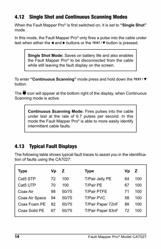
4.13 Typical Fault DisplaysThefollowingtableshowstypicalfaulttracestoassistyouintheidentifica-tion of faults using the CA7027:
Type Vp Z Type Vp Z
Cat5 STP 72 100 T/Pair Jelly PE 64 100Cat5 UTP 70 100 T/Pair PE 67 100Coax Air 98 50/75 T/Pair PTFE 71 100Coax Air Space 94 50/75 T/Pair PVC 58 100Coax Foam PE 82 50/75 T/Pair Paper 72nF 88 100Coax Solid PE 67 50/75 T/Pair Paper 83nF 72 100

Fault Mapper Pro® Model CA7027 15
CHAPTER 5
MAINTENANCE
Use only factory specified replacement parts.AEMC® will not be heldresponsible for anyaccident, incident, ormalfunction followinga repairdone other than by its service center or by an approved repair center.
5.1 Changing the Battery
Disconnect the instrument from any cable or network link.
1. Turn the instrument OFF.
2. Loosenthe2screwsandremovethebatterycompartmentcover.
3. Replacethebatterieswith4x1.5VAAalkalinebatteries,observingthe polarities.
4. Reattach the battery compartment cover.
5.2 Cleaning
Disconnect the instrument from any source of electricity.
• Useasoftclothlightlydampenedwithsoapywater.
• Rinsewithadampclothandthendrywithadrycloth.
• Donotsplashwaterdirectlyontheinstrument.
• Donotusealcohol,solventsorhydrocarbons.
5.3 StorageIf the instrument is not used for a period of more than 60 days, it is recom-mended to remove the batteries and store them separately.

16 Fault Mapper Pro® Model CA7027
Repair and Calibration
Toensurethatyourinstrumentmeetsfactoryspecifications,werecommendthat it be scheduled back to our factory Service Center at one-year intervals forrecalibration,orasrequiredbyotherstandardsorinternalprocedures.
For instrument repair and calibration:Youmust contactourServiceCenter foraCustomerServiceAuthorizationNumber(CSA#).Thiswillensurethatwhenyourinstrumentarrives,itwillbetrackedandprocessedpromptly.PleasewritetheCSA#ontheoutsideoftheshipping container.
Ship To: Chauvin Arnoux®, Inc. d.b.a. AEMC® Instruments15 Faraday DriveDover,NH03820USAPhone: (800) 945-2362 (Ext. 360)
(603) 749-6434 (Ext. 360)Fax: (603) 742-2346 or (603) 749-6309E-mail: [email protected]
(Orcontactyourauthorizeddistributor)Costs for repair and standard calibration are available.NOTE: You must obtain a CSA# before returning any instrument.
Technical and Sales Assistance
If you are experiencing any technical problems, or require any assistancewiththe proper operation or application of your instrument, please call, fax or e-mail our technical support team:
Chauvin Arnoux®, Inc. d.b.a. AEMC® Instruments Phone: (800) 945-2362 (Ext. 351)
(603) 749-6434 (Ext. 351)Fax: (603) 742-2346E-mail: [email protected]
Contact:

Fault Mapper Pro® Model CA7027 17
Limited Warranty
TheModelCA7027iswarrantedtotheownerforaperiodof2yearsfromthedate of original purchaseagainst defects inmanufacture. This limitedwar-ranty is given by AEMC®Instruments,notbythedistributorfromwhomitwaspurchased.Thiswarrantyisvoidiftheunithasbeentamperedwith,abusedorif the defect is related to service not performed by AEMC® Instruments.
For full and detailed warranty coverage, please read the Warranty Coverage Information, which is attached to the Warranty Registration Card (if enclosed) or is available at www.aemc.com. Please keep the Warranty Coverage Information with your records.
What AEMC® Instruments will do: Ifamalfunctionoccurswithinthewarranty period,youmayreturntheinstrumenttousforrepair,providedwehaveyourwarranty registration information on file or a proof of purchase. AEMC®Instrumentswill,atitsoption,repairorreplacethe faulty material.
REGISTER ONLINE AT:www.aemc.com
Warranty Repairs
What you must do to return an Instrument for Warranty Repair: First, request aCustomerServiceAuthorizationNumber (CSA#) by phoneorbyfaxfromourServiceDepartment(seeaddressbelow),thenreturntheinstrumentalongwith thesignedCSAForm.Pleasewrite theCSA#on theoutside of the shipping container. Return the instrument, postage or shipment pre-paid to:
Ship To: Chauvin Arnoux®, Inc. d.b.a. AEMC® Instruments15FaradayDrive•Dover,NH03820USAPhone: (800) 945-2362 (Ext. 360)
(603) 749-6434 (Ext. 360)Fax: (603) 742-2346 or (603) 749-6309E-mail: [email protected]
Caution:Toprotectyourselfagainstin-transitloss,werecommendyouinsureyour returned material.
NOTE: You must obtain a CSA# before returning any instrument.

10/18
99-MAN100361v5
Chauvin Arnoux®, Inc. d.b.a. AEMC® Instruments15FaradayDrive•Dover,NH03820USA•Phone:(603)749-6434•Fax:(603)742-2346
www.aemc.com