Embed Size (px)
Citation preview
CZASOPISMO INŻYNIERII LĄDOWEJ, ŚRODOWISKA I ARCHITEKTURY JOURNAL OF CIVIL ENGINEERING, ENVIRONMENT AND ARCHITECTURE JCEEA, t. XXXV, z. 65 (2/18), kwiecień-czerwiec 2018, s. 157-166, DOI:10.7862/rb.2018.32
Tomasz SIWOWSKI1 Maciej KULPA2
FATIGUE TESTS OF WELDED JOINTS IN STEEL ORTHOTROPIC BRIDGE DECK
The procedure supported by testing has been used for the fatigue assessment of the existing steel bridge with the orthotropic deck, built in the early 80’s of the XX century. The main goal was to check if the remaining fatigue life of the existing steel deck is at least 25 years, without the need of extensive repair or strengthening. The assessment comprised the fatigue calculation according to European codes with the use of updated values for material resistance. In order to obtain the updated information on material resistance the fatigue testing was carried out and the actual fatigue resistance ΔσC was applied in damage accumulation calculation. The fatigue tests were carried out for two most critical deck details. Test specimens were cut out of the existing deck at the locations where the preliminary analysis showed the possible highest stress ranges. The assessment based on the actual material resistance revealed that the bridge deck had got very long service life. The main results of the fatigue assessment of orthotropic steel deck supported by testing have been presented in the paper.
Keywords: welded connections, orthotropic deck, fatigue testing, service life
1. Introduction
Steel bridges with orthotropic decks have been built worldwide over the past 60 years due to their advantages, such as high carrying capacity, low weight, rapid construction and life-cycle economy [10]. However, the detailing of the welded connections and the execution of welding was not always carried out in the most optimal way. This has resulted in fatigue cracks in orthotropic decks during their service life. Nowadays, due to the higher wheel loads and the increased traffic, steel bridges with orthotropic decks are more subject to fatigue loading than in the past. A number of these bridges have suffered fatigue cracks. Although cracks are found at many deck locations, they usually do not threaten the performance of the bridge immediately [3]. Repairs, however, generate additional expenses as bridge decks are large areas thus include many spots to be repaired. 1 Corresponding author: Tomasz Siwowski, Rzeszow University of Technology, ul. Poznańska 2,
[email protected] 2 Maciej Kulpa, Rzeszow University of Technology, ul. Poznańska 2, [email protected]
158 T. Siwowski, M. Kulpa
Steel bridges with orthotropic decks have been built in Poland since early 70’s of the XXth century. One of the biggest is the Grot-Rowecki Bridge across the Vistula River in Warsaw, built in 1981. The bridge is a key element of the traffic network of Poland. It is the busiest Polish bridge located along the strategic DK-8 national road. Several years ego the decision was made to alter the Warsaw section of the DK-8 into S-8 expressway, which caused the modernization (widening and strengthening) of the bridge was required. Before the final technical solutions were approved, the comprehensive evaluation of the technical condition had been carried out by Rzeszow University of Technology (RUT). One of the most important part of this evaluation was the thorough fatigue assessment of the orthotropic steel deck. The main goal of that assessment was to check if the remaining fatigue life of the existing deck would be at least 25 years without the need of extensive repair or strengthening.
In case of the existing steel bridges with orthotropic decks there are numerous approaches how to estimate their remaining fatigue life [1], [2], [5]. A classification system of assessment levels is presented in the joint JRC-ECCS report [4], which offers the recommendations to provide technical insight on the way the existing steel structures could be assessed. For the fatigue assessment of existing welded structures the detail categories ΔσC given in [7] should be used, if the actual weld geometry is close to the ones produced today by manual arc welding. If not, or to make this procedure more reliable the specific fatigue tests need to be carried out. The procedure supported by testing has been used for the fatigue assessment of the existing steel bridge with the orthotropic deck. The fatigue tests were carried out for deck’s critical details (welds). Test specimens were cut out of the existing orthotropic deck where the preliminary analysis showed the possible highest stress ranges. The updated information on material resistance was used and the actual fatigue resistance ΔσC was applied in fatigue assessment according to recommendations [4]. The main results of fatigue assessment along with fatigue test results have been presented in the paper.
2. Bridge description
The Grot-Rowecki Bridge is one of the first Polish biggest steel bridges equipped in an orthotropic steel deck, very modern in those days. It has the total length of 646 m and consists of two parallel and independent steel box structures. The bridge superstructure is a seven-span continuous beam with the span lengths of 3 × 75 + 2 × 90 + 120 + 60 m. The two biggest spans located directly over the river bed have the one-box cross-section (Fig. 1a), the remaining spans are two-girder plated structures with the constant depth of 4.1 m of all girders. It is the widest bridge in Warsaw (2 × 18.5 m), located along the north by-pass of the city, and hosts 4 traffic lanes of 3 × 3.5 m + 3.0 m and one sidewalk of 1.6 m.

Fatigue Test of Welded Joints in Steel Orthotropic Bridge Deck 159
Fig. 1. The Grot-Rowecki Bridge: general view of box girders (left), the orthotropic deck (right)
The orthotropic bridge deck consists of steel plates stiffened with longitudinal trapezoidal closed stiffeners and T-shaped cross-beams (Fig. 1b). The thickness of the deck plate varies from 12 mm in the middle to 28 mm in the support regions of the spans. The trapezoidal stiffeners are made of cold-formed 8-mm plates and continuously go through the webs of cross-beams. The axial distance of the stiffeners is 600 mm and their depth is 178 mm. The cross-beams are made up of 12-mm web with the depth of 850 mm and bottom flange with 20 × 400 mm cross-section. They are placed every 2 500 mm along the bridge. The whole steel superstructure was completely welded and is made of 18G2A steel grade (S-355 according to current codes).
The technical state of the orthotropic deck of Grot-Rowecki Bridge after 30 years of service was described in [11]. In the bridge supervisions conducted during last years the special attention was paid to the orthotropic deck in particular. However, no serious damages were observed in this bridge. Recently, the visual inspection of the deck structure has been also carried out by the RUT as a part of the preliminary evaluation before fatigue assessment.
3. Selection of fatigue – prone welds
In order to identify the welded connections which are critical in terms of fatigue, apart from the visual inspection of the deck structure, the calculations were conducted and the critical regions were chosen for preliminary evaluation of the deck (Fig. 2). For the calculation of stress ranges in the chosen details, the part of the orthotropic deck with the length of 13.0 m was modelled, comprising 5 spans of longitudinal stiffeners supported on 6 cross-beams. A beam and shell elements in FEM Sofistik-code environment were used for deck modelling. Using 3-D structural model of the orthotropic deck, the inner forces and corresponding maximum and minimum stresses in all relevant details were calculated and followed by establishing stress ranges applied for the fatigue evaluation [9].

160 T. Siwowski, M. Kulpa
Fig. 2. Critical welds of the deck chosen for preliminary evaluation
The Fatigue Load Model No. 3 (FLM 3) according to [10] was used to generate stress ranges in the details under consideration. Equivalent damage coefficients λ1 - λ4 according to [8] for the bridge were determined. For welded joints in the orthotropic deck the values of ΔσC were applied according to [7]. Fatigue safety coefficient γFf = 1.0 according to [6] and partial factor γMf = 1.15 for high consequences of failure according to [7] were also applied. The fatigue assessment was undertaken using damage tolerant method.
Table 1 shows the fatigue safety calculations (μfat) for selected critical details (Fig. 2). This way two critical details of the deck were determined with the fatigue safety level μfat < 1.0: the fillet weld connecting the deck to trapezoidal stiffener (detail no. 1 in Fig. 2) and the splice joint in stiffener, full penetration butt weld with steel backing plate (detail no. 4 in Fig. 2).
Table 1. Fatigue safety calculations (ΔσE,2, μfat) for selected critical welds
Detail Δσp λ ΔσE,2 ΔσC μfat Fatigue safety
μfat > 1,0 1 57.2
1.31
74.9 71 0.70 no – check level 2 2
33.4 43.8 80 1.35 yes
3 yes 4 40.0 52.4 50 0.71 no – check level 2
Once the critical construction details were found, the detailed investigation
of the remaining fatigue life supported by testing could be done. Because the actual weld geometry is not the same to the ones produced today and to make the assessment procedure more reliable, the fatigue tests were decided to be carried out. On the other side, a more refined load model, composed of the different types of lorries crossing the bridge, was applied in the further calculation. The Fatigue Load Model No. 4 (FML 4) given in [6] and adjusted to the actual bridge service situation was taken into consideration [9].

Fatigue Test of Welded Joints in Steel Orthotropic Bridge Deck 161
4. Fatigue testing
For the reliable fatigue assessment of existing welded structures the detail categories ΔσC given in [7] should be determined by means of the specific fatigue tests. In our case the fatigue tests were carried out for both critical details (no. 1 and no. 4). Test specimens were cut out of the existing orthotropic deck (Fig. 3).
Fig. 3. Fatigue test specimens: weld no. 1 (left), weld no. 4 (right)
Detail no. 1 was the fillet weld connecting the deck slab to the trapezoidal stiffener (Fig. 2). In this case the fatigue assessment is based on the direct stress range from bending of the deck plate. Therefore the main point of interest was the fatigue strength of the deck plate under the bending stresses imposed by wheel loading. Testing was carried out on full-scale one-stiffener specimens, consisted of a 300-mm-long single stiffener with accompanying part of the deck plate 700 mm wide (Fig. 3a). Twelve test specimens were cut out of three different parts of the deck, located on three relevant spans of the bridge and along the slow lanes of the deck.
The test involved one mode of fatigue loading at the frequency of 5 Hz, i.e. on the deck at the stiffener centre-line, with the specimen supported symmetrically (Fig. 4a). Using the test specimen and the loading shown in Figure 4a the approximation of the actual loading conditions was achieved. The load value F and relevant stresses in the vicinity of fillet weld was evaluated
Fig. 4. Detail no.1 under testing: loading scheme (left), typical fatigue failure (right)

162 T. Siwowski, M. Kulpa
on the basis of the FEM calculations using the numerical model of specimen validated against the strain measurement done on the actual bridge deck before fatigue specimens were cut out. The stress ratio at the weld toe in the deck plate was assumed as R = 0.1 with constant amplitude loading.
The series of 6 specimens was tested at the stress ranges Δσ between 160 and 220 MPa. All specimens failed in the weld as a result of fatigue crack propagation from the weld root through the stiffener (Fig. 4b). It was induced by the transverse bending of the deck plate. The results of the tests of a fillet weld connecting the deck plate to the trapezoidal stiffener are shown in Table 2.
Table 2. Results of fatigue testing of the detail no. 1
No. Δσ [MPa]
Fmin [kN]
Fmax [kN]
ΔF [kN]
Number of cycles N
1 160 1.09 10.9 9.8 2,763,055 2 170 1.16 11.58 10.42 1,652,000 3 180 1.22 12.25 11.02 2,233,811 4 190 1.29 12.93 11.64 1,313,332 5 200 1.36 13.61 12.25 889,523 6 220 1.49 14.97 13.48 636,615
Detail no. 4 was the splice joint in a stiffener, full penetration butt weld
with steel backing plate (Fig. 2). In this case the fatigue assessment is based on the direct stress range Δσ in the stiffener. Testing was carried out on small strip specimens cut out of the full-scale splice joint. This was a tensile fatigue test on a butt-jointed plate, 600 × 90 × 12 mm thick (Fig. 3b). These test specimens were cut out of four different parts of the deck, located on four relevant spans of the bridge and along the slow lanes of the deck.
The small strip specimens were loaded in tension at a frequency of 5 Hz. The stress ratio at the weld in the stiffener bottom plate was assumed as R = 0.1 with constant amplitude loading. The series of 7 specimens was tested at the stress ranges Δσ between 120 and 200 MPa. Most specimens failed in the weld as a result of fatigue crack propagation from the weld root through the plate (Fig. 5b). One run-out was observed at Δσ = 120 MPa. The results of the tests on a penetration butt weld with steel backing plate in stiffener are shown in Table 3.
Fatigue Test of Welded Joints in Steel Orthotropic Bridge Deck 163
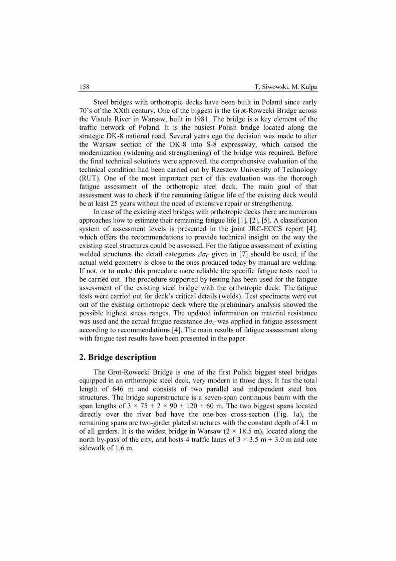
Fig. 5. Detail no. 1 under testing: loading scheme (left), typical fatigue failure (right)
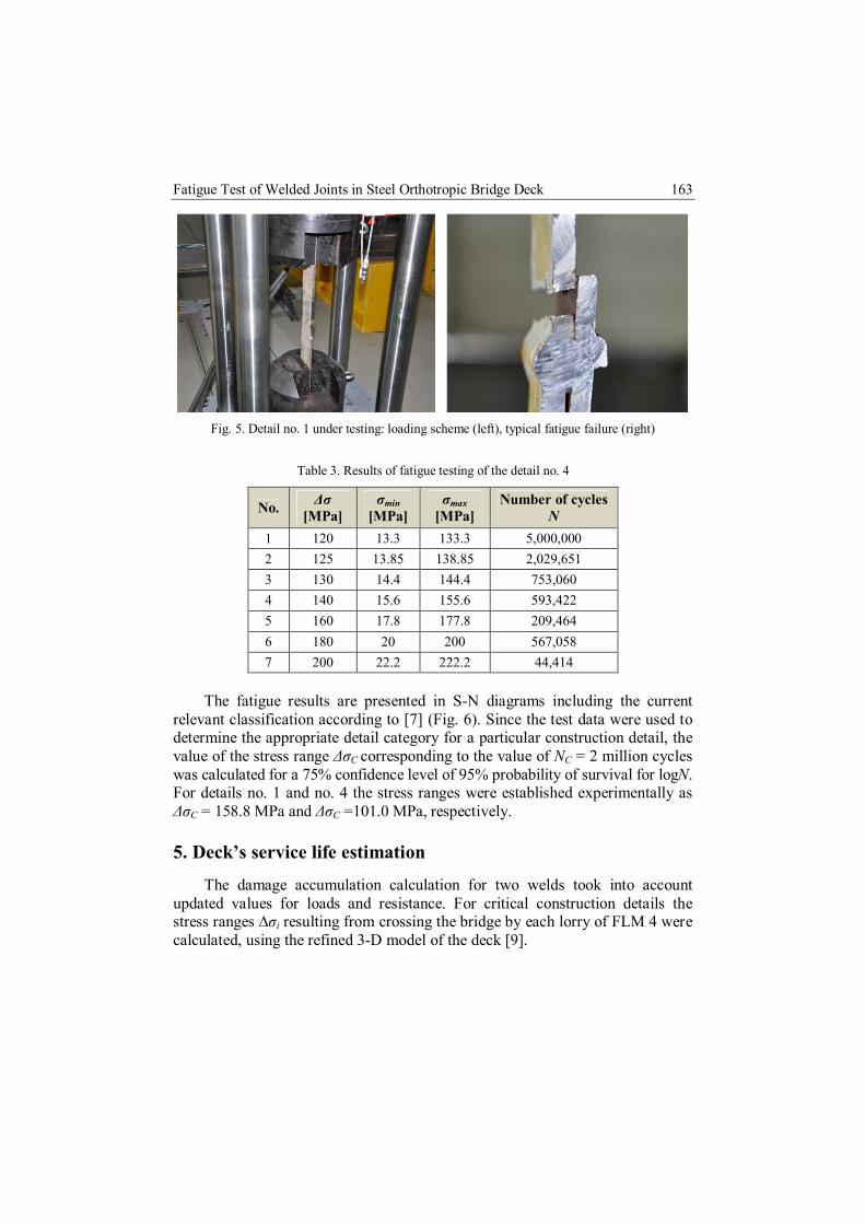
Table 3. Results of fatigue testing of the detail no. 4
No. Δσ [MPa]
σmin [MPa]
σmax [MPa]
Number of cycles N
1 120 13.3 133.3 5,000,000 2 125 13.85 138.85 2,029,651 3 130 14.4 144.4 753,060 4 140 15.6 155.6 593,422 5 160 17.8 177.8 209,464 6 180 20 200 567,058 7 200 22.2 222.2 44,414
The fatigue results are presented in S-N diagrams including the current
relevant classification according to [7] (Fig. 6). Since the test data were used to determine the appropriate detail category for a particular construction detail, the value of the stress range ΔσC corresponding to the value of NC = 2 million cycles was calculated for a 75% confidence level of 95% probability of survival for logN. For details no. 1 and no. 4 the stress ranges were established experimentally as ΔσC = 158.8 MPa and ΔσC =101.0 MPa, respectively.
5. Deck’s service life estimation
The damage accumulation calculation for two welds took into account updated values for loads and resistance. For critical construction details the stress ranges ∆σi resulting from crossing the bridge by each lorry of FLM 4 were calculated, using the refined 3-D model of the deck [9].

164 T. Siwowski, M. Kulpa
Fig. 6. S-N diagram for the detail no. 1 (top) and no. 4 (bottom) against the relevant curves [7]
The number of cycles occurring at each stress range magnitude γFf Δσi of a stress spectrum was calculated on the basis of estimated Nobs of the FML4. Thus the stress history for the selected deck details was established. The number NRi was determined using updated material resistance information, i.e. the actual S-N curves based on fatigue testing (Fig. 6). In Table 4 the service life estimation for the detail no. 1 was shown, including 33 years of up-to-date service and additional 25 years required by the road administration. The damage accumulation calculation accounts the curve established with fatigue testing and – for comparison – the S-N curve according to [7]. The practically unlimited service lives for both deck details were obtained: 7.80E+02 and 1.80E+02 years for detail no. 1 and no. 4 respectively. However, using the standard S-N curve according to [7] in both cases the service life of the deck was exhausted. Thus the fatigue calculation clearly revealed the influence of the updated information on material resistance on the final fatigue assessment result.
Fatigue Test of Welded Joints in Steel Orthotropic Bridge Deck 165
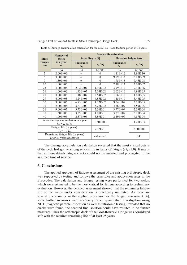
Table 4. Damage accumulation calculation for the detail no. 4 and the time period of 33 years
Stres ranges
Δσi
Number of cycles
in a year ni
Service life estimation According to [8] Based on fatigue tests
Endurance Ni
ni / Ni Endurance
Ni ni / Ni
(a) (b) (a) / (b) (c) (a) / (c) 2 2.00E+06 ∞ 0 1.11E+16 1.80E-10 5 3.00E+05 ∞ 0 9.89E+13 3.03E-09 7 1.30E+06 ∞ 0 1.75E+13 7.45E-08
10 1.00E+06 ∞ 0 2.78E+12 3.60E-07 23 3.00E+05 2.62E+07 1.15E-02 3.79E+10 7.91E-06 26 1.00E+06 1.42E+07 7.04E-02 2.02E+10 4.96E-05 27 3.00E+05 1.18E+07 2.54E-02 1.66E+10 1.81E-05 29 4.00E+05 8.24E+06 4.85E-02 1.15E+10 3.48E-05 30 3.00E+05 6.95E+06 4.32E-02 9.64E+09 3.11E-05 35 2.00E+05 3.83E+06 5.22E-02 4.36E+09 4.59E-05 36 9.00E+05 3.52E+06 2.56E-01 3.77E+09 2.39E-04 37 1.30E+06 3.25E+06 4.00E-01 3.27E+09 3.97E-04 40 1.00E+06 2.57E+06 3.89E-01 2.19E+09 4.57E-04
Linear damage cummulation in a year: Dd = Σ ni / Ni
1.30E+00
1.28E-03
Fatigue life (in years): TS = 1 / Dd
7.72E-01 7.80E+02
Remaining fatigue life (in years) after 33 years of service exhausted 747
The damage accumulation calculation revealed that the most critical details
of the deck had got very long service life in terms of fatigue (Dd «1.0). It means that in these details fatigue cracks could not be initiated and propagated in the assumed time of service.
6. Conclusions The applied approach of fatigue assessment of the existing orthotropic deck
was supported by testing and follows the principles and application rules in the Eurocodes. The calculation and fatigue testing were performed for two welds, which were estimated to be the most critical for fatigue according to preliminary evaluation. However, the detailed assessment showed that the remaining fatigue life of the welds under consideration is practically unlimited. As there are several uncertainties in the applied procedure for the fatigue assessment [4], some further measures were necessary. Since quantitative investigation using NDT (magnetic particle inspection as well as ultrasonic testing) revealed that no cracks were found, the adapted final solution could have resulted in no further measures. Thus the orthotropic deck of the Grot-Rowecki Bridge was considered safe with the required remaining life of at least 25 years.

166 T. Siwowski, M. Kulpa
References
[1] Aygül M., Al-Emrani M., Urushadze S.: Modelling and fatigue life assessment of orthotropic bridge deck details using FEM, International Journal of Fatigue, vol. 40, no. 7, 2012, pp. 129–142.
[2] Battista R.C., Pfeil M.S., Carvalho E.M.L.: Fatigue life estimates for a slender orthotropic steel deck, Journal of Constructional Steel Research, vol. 64, no. 1, 2008, pp. 134–143.
[3] Kolstein M.H.: Fatigue classification of welded joints in orthotropic steel bridge decks, Delft University of Technology, Delft, The Netherlands, 2007.
[4] JRC Scientific and Technical Reports: Assessment of existing steel structures: recommendations for estimation of remaining fatigue life, Report No. 43401, Joint Research Centre, European Commission, Luxembourg, 2008.
[5] Maljaars J., Dooren F., Kolstein H.: Fatigue assessment for deck plates in orthotropic bridge decks, Steel Construction, vol. 5, no. 2, 2012, pp. 93–100.
[6] PN-EN 1991-2. Eurocode 1: Actions on structures. Part 2: Traffic loads on bridges. The Polish Committee for Standardization, Warsaw, 2003.
[7] PN-EN 1993-1-9. Eurocode 3: Design of steel structures. Part 1-9: Fatigue. The Polish Committee for Standardization, Warsaw, 2005.
[8] PN-EN 1993-2. Eurocode 3: Design of steel structures. Part 2: Steel bridges. The Polish Committee for Standardization, Warsaw, 2006.
[9] Siwowski T., Kozłowski A., Kulpa M.: Fatigue assessment of orthotropic steel deck in existing road bridge. Proceedings of SBIC-2015 – the International Symposium on Steel Bridges: Innovation & New Chalanges, Istambul, Turky, 2015.
[10] Troitsky M.S.: Orthotropic bridges – theory and design, James F. Lincoln Arc Welding Foundation, Cleveland, USA, 1987.
[11] Zobel H., Karwowski W., Mossakowski P., Wróbel M.: Pomosty ortotropowe niektórych mostów drogowych po wieloletniej eksploatacji, Inżynieria i Budownictwo, vol. 65, nr 6, 2009, pp. 306–311.
Przesłano do redakcji: 04.05.2018 r. Przyjęto do druku: 15.06.2018 r.


![[Corus] Design of SHS Welded Joints](https://img.dokumen.tips/doc/110x75/577d1fe51a28ab4e1e918f6a/corus-design-of-shs-welded-joints.jpg)