Embed Size (px)
Citation preview
4.2-1
4.2 Design Rules For Welded Joints (Revision 3)
4.2.0 Table of Contents............................................................................................................ 1 4.2.1 Scope ............................................................................................................................... 1 4.2.2 Weld Category................................................................................................................. 1 4.2.3 Weld Joint Type............................................................................................................... 1 4.2.4 Weld Joint Factor............................................................................................................ 1 4.2.5 Types of Joints Permitted .............................................................................................. 1 4.2.6 Nomenclature .................................................................................................................. 7 4.2.7 Tables............................................................................................................................... 9 4.2.8 Figures ........................................................................................................................... 48
4.2.1 Scope Design requirements for weld joints are provided in this paragraph. Acceptable weld joint details are provided for most configurations, alternative details may be used if they can be qualified by a design procedure. Rules for sizing welds are also provided.
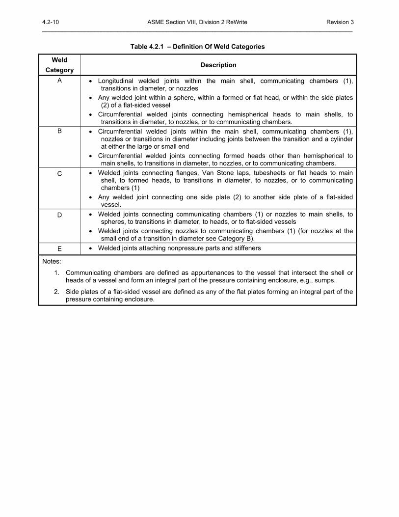
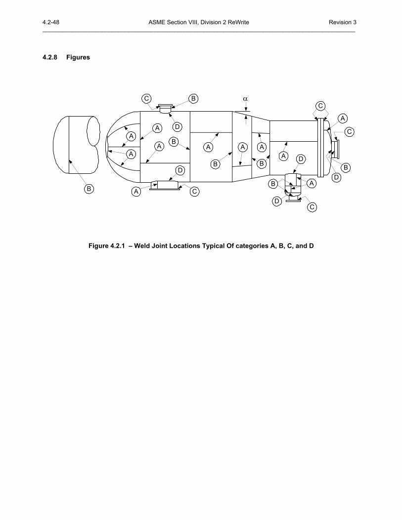
4.2.2 Weld Category The term weld category defines the location of a joint in a vessel, but not the weld joint type. The weld categories established by this paragraph are for use elsewhere in this Division in specifying special requirements regarding joint type and degree of examination for certain welded pressure joints. Since these special requirements that are based on thickness do not apply to every welded joint, only those joints to which special requirements apply are included in categories. The weld categories defined in Table 4.2.1 and shown in Figure 4.2.1.
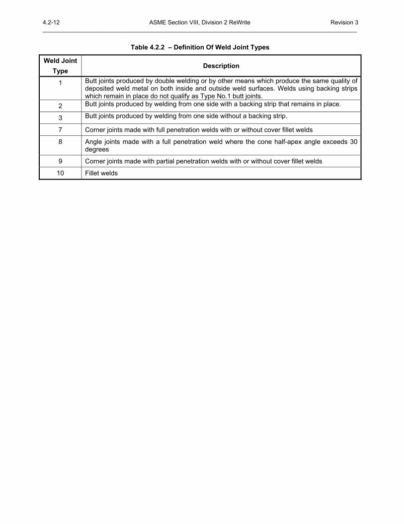
4.2.3 Weld Joint Type The weld joint type defines the type of weld between pressure and/or nonpressure parts. The definitions for the weld joint types are shown in Table 4.2.2.
4.2.4 Weld Joint Factor The weld joint factor of a welded joint is expressed as a numerical quantity and is used in the design of a joint as a multiplier of the appropriate allowable stress value taken from Annex 3.A. The weld joint factor shall be determined from Table 7.1.
4.2.5 Types of Joints Permitted
4.2.5.1 Definitions
a) Butt Joint � A butt joints is a connection between two the edge of two members with a full penetration weld. The weld is a double sided or single sided groove weld that extends completely through both of the parts being joined.
b) Corner Joint � A corner joints is a connection between two members at right angles to each other in the form of an L or T that is made with a full or partial penetration weld.
c) Full Penetration Corner Joint � A full penetration corner joints is a connection between two members at right angles to each other in the form of an L or T that is made with a full penetration weld. Welds in full penetration corner joints shall be groove welds extending completely through at least one of the parts being joined and shall be completely fused to each part.
d) Fillet Weld � A fillet weld is a weld that is approximately triangular in cross section that joins two surfaces at approximately right angles to each other.
e) Gross Structural Discontinuity � A gross structural discontinuity is a source of stress or strain intensification which affects a relatively large portion of a structure and has a significant effect on the overall stress or strain pattern or on the structure as a whole. Examples of gross structural discontinuities are head-to-shell and flange-to-shell junctions, nozzles, and junctions between shells of different diameters or thicknesses.
4.2-2 ASME Section VIII, Division 2 ReWrite Revision 3 _______________________________________________________________________________________________ f) Lightly Loaded Attachments � Weld stress due to mechanical loads on attached member not over 25%
of allowable stress for fillet welds and temperature difference between shell and attached member not expected to exceed 14°C (25°F) shall be considered lightly loaded.
g) Minor Attachments � Parts of small size, 10 mm (0.375 in.) thick or 82 cm3 (5 in3 ) in volume, that carry no load or an insignificant load such that a stress calculation in designer's judgment is not required; examples include nameplates, insulation supports, and locating lugs.
h) Major Attachments � Cover attachment of parts that are not minor or lightly loaded as described above.
4.2.5.2 Category A Locations
a) All joints of Category A shall be Type No. 1 butt joints.
b) Acceptable Weld Category A welds are shown in Tables 4.2.4 and 4.2.5.
c) Transition Joints Between Sections Of Unequal Thickness � Unless the requirements of Part 5 are shown to be satisfied, a tapered transition shall be provided at joints between sections that differ in thickness by more than one-fourth of the thickness of the thinner section or by more than 3 mm (0.125 in.). The transition may be formed by any process that will provide a uniform taper. When Part 5 is not used, the following additional requirements shall also apply.
1) When a taper is required on any shell section intended for butt welded attachment, the transition geometry shall be in accordance with Table 4.2.4, Details 4, 5, and 6.
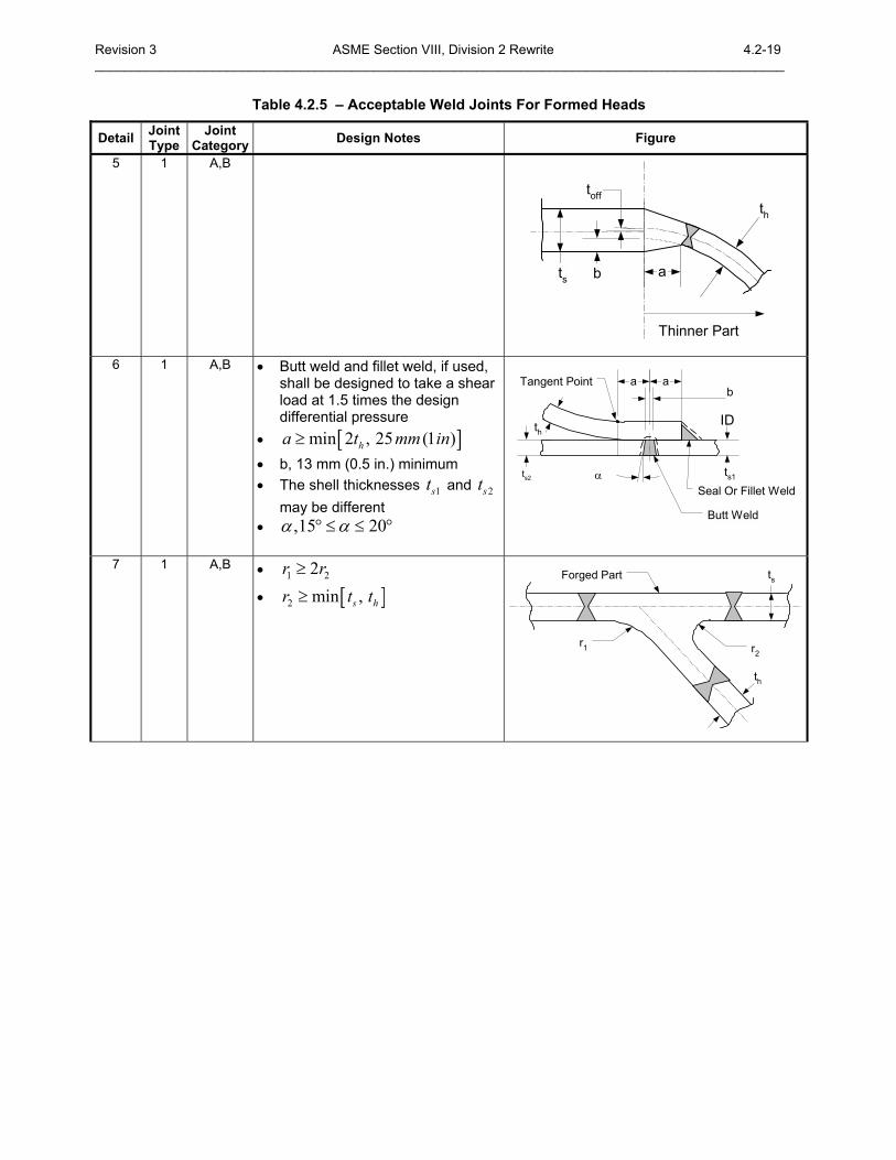
2) When a taper is required on any formed head intended for butt welded attachment, the transition geometry shall be in accordance with Table 4.2.5, Details 2, 3, 4 and 5.
3) An ellipsoidal or hemispherical head which has a greater thickness than a cylinder of the same inside diameter may be machined to the outside diameter of the cylinder provided the remaining thickness is at least as great as that required for a shell of the same diameter.
4) When the transition is formed by adding additional weld metal beyond what would otherwise be the edge of the weld, such additional weld metal buildup shall be subject to the requirements of Part 6. The butt weld may be partly or entirely in the tapered section.
5) The requirements of this paragraph do not apply to flange hubs.
4.2.5.3 Category B Locations
a) The joints of Category B may be any of the following types:
1) Type No. 1 butt joints,
2) Type No.2 butt joints except as limited in paragraph 4.2.5.7,
3) Type No. 3 butt joints may only be used for shell thickness with a wall thickness of 16 mm (0.625 in.) or less and a diameter of 610 mm (or 24 in.) and less.
b) Acceptable Weld Category B welds are shown in Tables 4.2.4 and 4.2.5.
c) Backing strips shall be removed from Type No. 2 butt joints unless access conditions prevent their removal. If a fatigue analysis of Type No. 2 butt joints with a backing strip in place is required, then a stress concentration factor of 2.0 for membrane stresses and of 2.5 for bending stress shall be applied.
d) Transition joints between shell sections of unequal thickness shall be in accordance with paragraph 4.2.5.2.c.
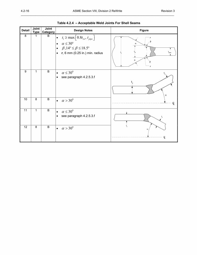
e) Transition joints between nozzle necks and attached piping of unequal thickness shall be made using a tapered transition in accordance with Table 4.2.4, Details 7 and 8.
f) When butt joints are required elsewhere in this Division for Category B, an angle joint connecting a transition in diameter to a cylinder shall be considered as meeting this requirement provided that the cone half apex angle does not exceed 30 deg and the requirements of Type No. 1 butt joints are met. All requirements pertaining to the butt joint shall apply to the angle joint.
4.2.5.4 Category C Locations
Revision 3 ASME Section VIII, Division 2 Rewrite 4.2-3 ______________________________________________________________________________________________ a) The joints of Category C may be any of the following types
1) Type No. 1 butt joints,
2) Full penetration corner joints except as limited in paragraph 4.2.5.7,
3) Fillet welded joints with the following limitations:
i) The materials of the flange and the part it is welded to are Type 1 Materials (see Table 4.2.3).
ii) The minimum specified yield strength of both materials is less than 552MPa (80 ksi).
iii) The minimum elongation of both materials is 12% in 51 mm (2 in.)
iv) The thickness of the materials to which the flange is welded does not exceed 32 mm (1.25 in.)
v) The fillet weld dimensions satisfy the requirements shown in Table 4.2.9.
vi) The fatigue analysis required for nozzles with separate reinforcement and non-integral attachments in Part 5 is applied to the design.
b) Acceptable Category C welds are shown in the following tables.
1) Table 4.2.6 � Acceptable weld joints for unstayed flat heads, tubesheets without a bolting flange, and side plates of rectangular pressure vessels
2) Table 4.2.7 � Acceptable weld joints with butt weld hubs
3) Table 4.2.8 � Acceptable weld joints for attachment of tubesheets with a bolting flange
4) Table 4.2.9 � Acceptable weld joints for flange attachments
c) Forged FIat Heads With Hubs for Butt Joints
1) Hubs for butt welding to the adjacent shell head, or other pressure parts such as tubesheets and flat heads as shown in Table 4.2.7 shall not be machined from flat plate. The hub shall be forged in such a manner as to provide in the hub the full minimum tensile strength and elongation specified for the material in the direction parallel to the axis of the vessel. Proof of this shall be furnished by a tension test specimen (subsize, if necessary) taken in this direction and as close to the hub as practical.
2) Flanges with hubs as shown in Table 4.2.9, Details 6, 7, and 8 shall not be machined from flat plate.
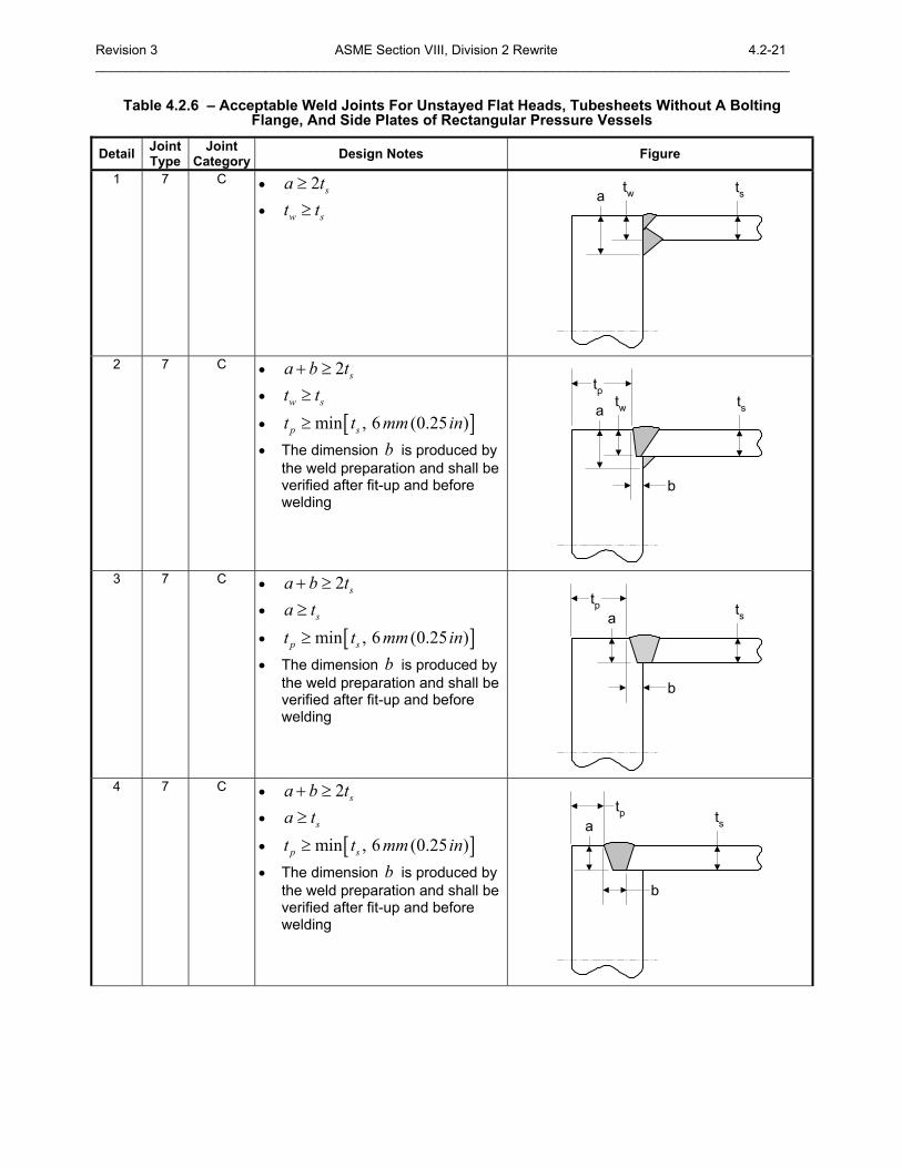
d) Corner Joints � If shells, heads, or other pressure parts are welded to a forged or rolled plate to form a corner joint as shown in Table 4.2.6 and Table 4.2.8, then the welds shall meet the following requirements.
1) On the cross section through the welded joint, the line between the weld metal and the forged or rolled plate being attached shall be projected on planes both parallel to and perpendicular to the surface of the plate being attached, in order to determine the dimensions a and b, respectively.
2) The dimensional requirements on a and b shall meet the applicable requirements in Tables 4.2.6 and Table 4.2.8.
3) Weld joint details that have a dimension through the joint that is less than the thickness of the shell, head, or other pressure part, or that provide attachment eccentric thereto are not permitted.
4) If an integral tubesheet is located between two shell, head, or other pressure parts, then a weld attachment detail shown in Table 4.2.6 shall be used for each attachment.
4.2.5.5 Category D Locations
a) The joints of Category D may be any of the following types.
1) Type No. 1 butt joints.
2) Full penetration corner joints except as limited in paragraph 4.2.5.7.
4.2-4 ASME Section VIII, Division 2 ReWrite Revision 3 _______________________________________________________________________________________________
3) Full penetration corner joints at the nozzle neck or fillet welds, or both.
4) Partial penetration corner joint at the nozzle neck.
b) Acceptable Category D welds are shown in the following tables.
1) Table 4.2.10 � Some acceptable full penetration welded nozzle attachments not readily radiographable
2) Table 4.2.11 � Some acceptable pad welded nozzle attachments and other connections to shells
3) Table 4.2.12 � Some acceptable fitting type welded nozzle attachments and other connections to shells
4) Table 4.2.13 � Acceptable welded nozzle attachments that are readily radiographable
5) Table 4.2.14 � Some acceptable partial penetration nozzle attachments
c) Requirements for nozzle welds are shown below.
1) Type No. 1 butt joints or full penetration joints shall be used when the opening is in a shell is 64 mm (2.5 in.) or more in thickness.
2) Nozzle Neck Abutting The Vessel Wall Without Reinforcement � Nozzle necks abutting the vessel wall without added reinforcing element shall be attached by a full penetration groove weld. Backing strips shall be used with welds deposited from only one side or when complete joint penetration cannot be verified by visual inspection. Backing strips, when used, shall be removed after welding. Permissible types of weld attachments are shown in Table 4.2.10, Details 1, 2, and 8.
3) Insert Nozzle Necks Without Reinforcement � Nozzle necks without added reinforcing elements inserted partially into or through a hole cut in the vessel wall and without additional reinforcing elements shall be attached by a full penetration groove weld. Backing strips, when used, shall be removed after welding. Permissible types of weld attachments are shown in Table 4.2.10, Details 3, 4, 5, 6, 7, and 9.
4) Insert Nozzle Necks With Reinforcement � Inserted type necks having added reinforcement in the form of one or more separate reinforcing plates shall be attached by welds at the outer edge of the reinforcement plate and at the nozzle neck periphery. The welds attaching the neck to the vessel wall and to the reinforcement shall be full penetration groove welds. Permissible types of weld attachments are shown in Table 4.2.11, Details 1, 2, and 3.
5) Studded Pad Type Connections � Studded connections which may have externally imposed loads shall be attached using full penetration welds in accordance with Table 4.2.11, Detail 5. Studded pad type connections on which there are essentially no external loads, such as manways and handholes used only as inspection openings, thermowell connections, etc., may be attached using fillet weld in accordance with Table 4.2.11, Detail 4.
6) Fittings With Internal Threads � Internally threaded fittings shall be limited to NPS 2 or smaller. Permissible types of weld attachments are shown in Table 4.2.12.
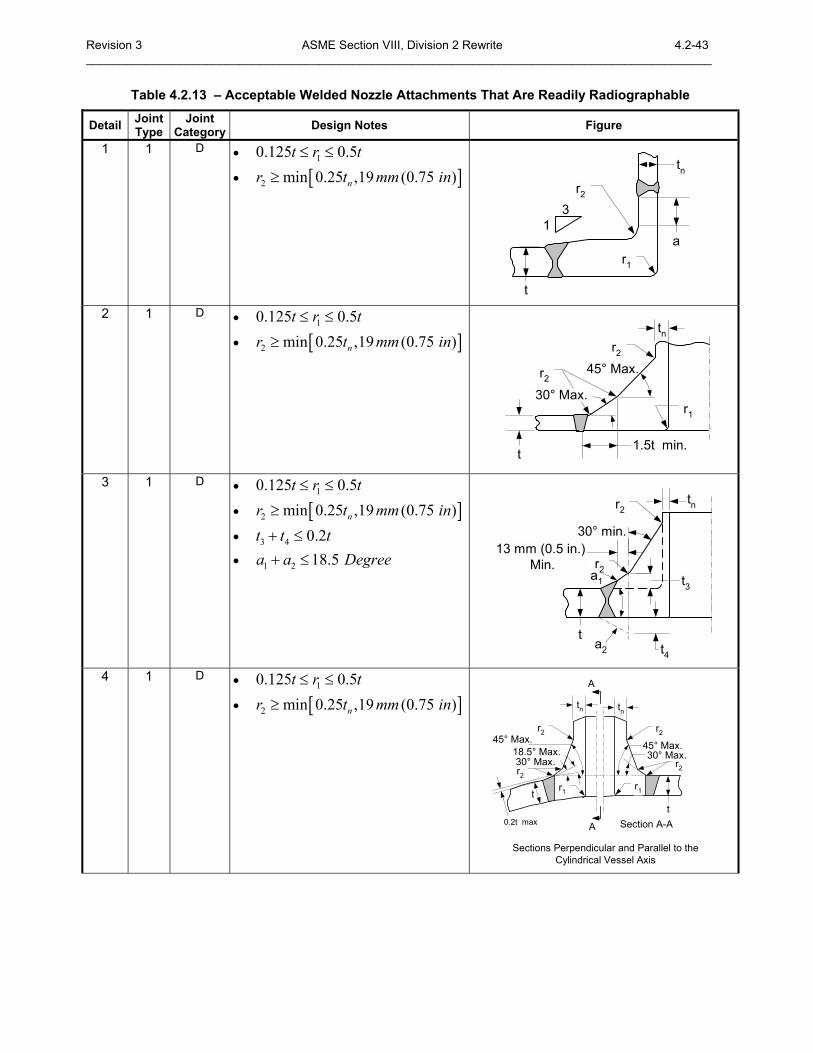
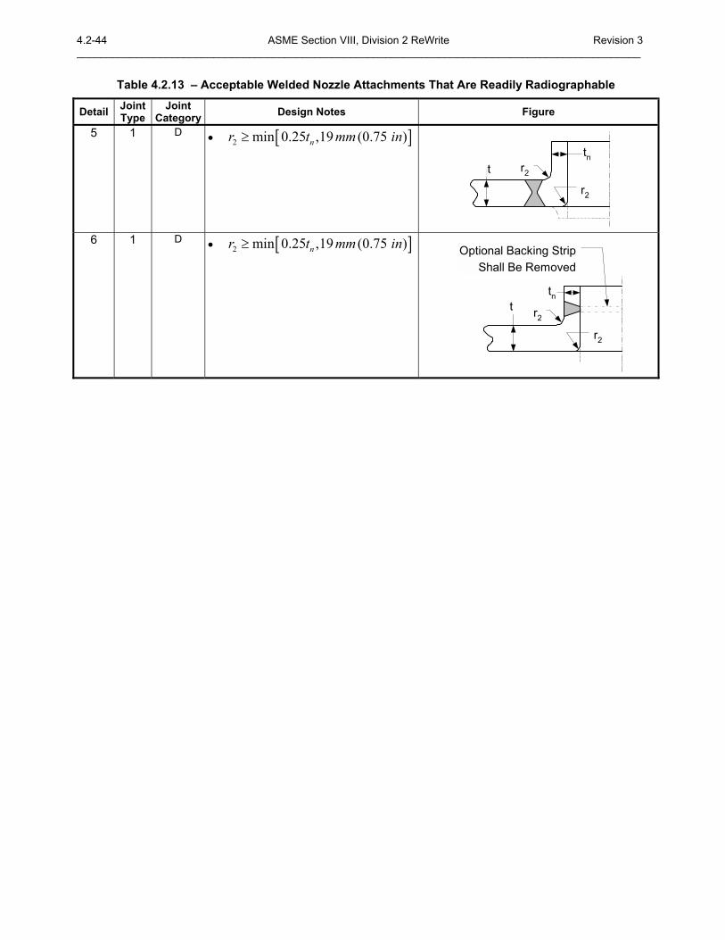
7) Nozzles With Integral Reinforcement � Nozzles having integral reinforcement may be attached using butt welds of Type No.1. Nozzles or other connections with integral reinforcement that are attached with corner welds shall be attached by means of full penetration corner welds. Permissible types of weld attachments are shown in Table 4.2.13.
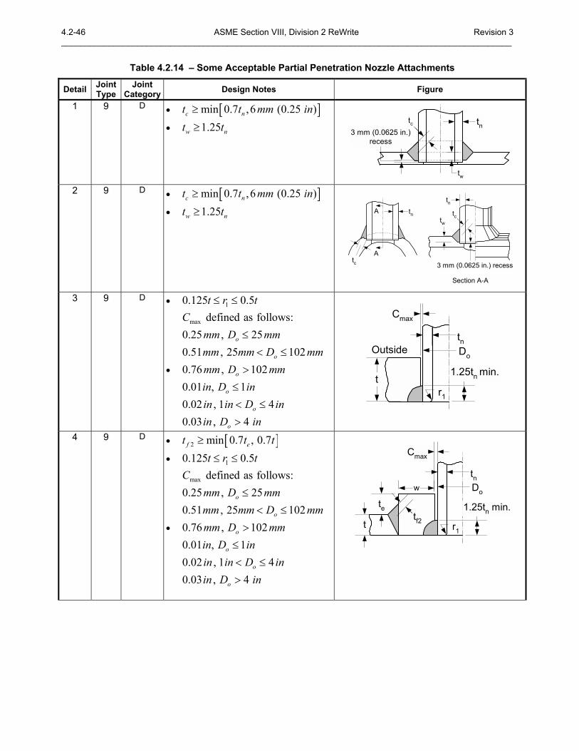
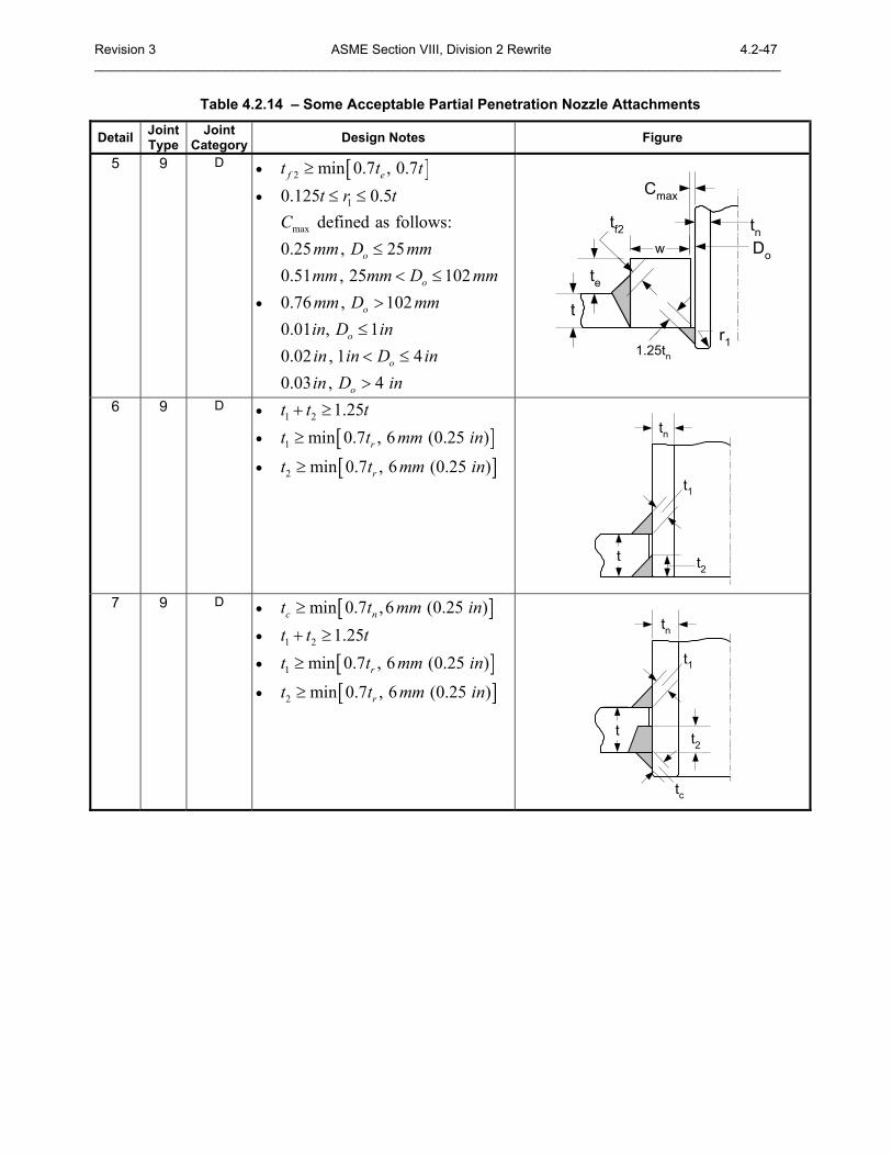
8) Nozzle Attached With Partial Penetration Welds � Partial penetration welds may be used only for nozzle attachments, such as instrumentation openings, inspection openings, etc., on which there are essentially no external mechanical loadings and on which there will be no thermal stresses greater than in the vessel itself. Permissible types of weld attachments are shown in Table 4.2.14. If Table 4.2.14, Details 3, 4, and 5 are used, then the material in the neck shall not be included in the reinforcement area calculation (see paragraph 4.5).
4.2.5.6 Category E Locations
a) Method Of Attachment � Attachment of nonpressure parts shall be in accordance with the following requirements.
Revision 3 ASME Section VIII, Division 2 Rewrite 4.2-5 ______________________________________________________________________________________________
1) Welded joints attaching nonpressure parts, supports, lugs, brackets, and stiffeners may be attached to the inside or outside wall using butt welds, full penetration groove welds, partial penetration welds, fillet welds, or stud welds.
2) Resistance welded studs may be used for minor attachments to nonpressure parts for all materials except those included in Material Type 2 (see Table 4.2.3).
3) Supports, lugs, brackets, stiffeners, and other attachments may be attached with stud bolts to the outside or inside of a vessel wall (see paragraph 4.15.5).
4) All attachments shall conform to the curvature of the shell to which they are to be attached.
5) All welds joining nonpressure parts to pressure parts may be continuous or non-continuous for Material Types 1, 3, and 4 (see Table 4.2.3)
6) All welds joining nonpressure parts to pressure parts shall be continuous for Material Type 2 (see Table 4.2.3)
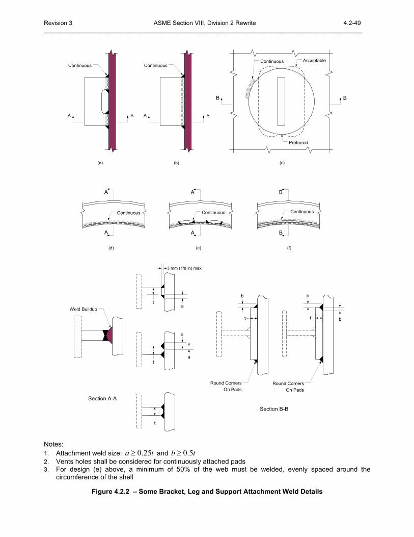
7) Some acceptable types of attachment weld and associated minimum weld sizes are shown in Figure 4.2.2, see paragraphs 4.2.5.6.e and 4.2.5.6.f for limitations.
b) Materials For Major Attachments to Pressure Parts � Attachments welded directly to pressure parts shall be of a material listed in Annex 3.A.
1) The material and the deposited weld metal shall be compatible with that of the pressure part.
2) For Material Type 2 (see Table 4.2.3), all permanent structural attachments that are welded directly to pressure parts shall be made of materials whose specified minimum yield strength is within ±20% of that of the material to which they are attached. An exception to this requirement is that lightly loaded attachments of non-hardenable austenitic stainless steels conforming to either SA-240, SA-312, or SA-479 are permitted to be fillet welded to pressure parts conforming to either SA-353, SA-553 Type 1 and Type 2, or SA-645.
c) Materials For Minor Attachments to Pressure Parts � Except as limited by paragraph 4.2.5.6.b or for forged fabrication (see paragraph 6.7), minor attachments may be of non-certified material and may be welded directly to the pressure part provided the requirements shown below are satisfied.
1) The material is identified and is suitable for welding.
2) The material is compatible insofar as welding is concerned with that to which the attachment is to be made.
3) The welds are postweld heat treated when required in Part 6.
d) Materials For Attachments Welded to Nonpressure Parts � Attachments welded to nonpressure parts may be of non-certified material, provided the material is identified, is suitable for welding, and is compatible with the material to which attachment is made.
e) Attachment Welds To Pressure Parts Of Material Types 1 and 4 (see Table 4.2.3) � Welds attaching nonpressure parts or stiffeners to pressure parts shall be one of the following:
1) A fillet weld not over 13 mm (0.5 in.) leg dimension and not closer than sRt from a gross structural discontinuity.
2) A partial penetration weld plus fillet weld; this is limited to the attachment of parts not exceeding 38 mm (1.5 in.) in thickness
3) A full penetration groove weld plus a fillet weld on each side
4) A full penetration butt weld; the prior deposition of weld metal to provide a boss for the butt weld is permissible provided it is checked for soundness by suitable nondestructive examination, heat treatment for the weld build-up region shall be considered.
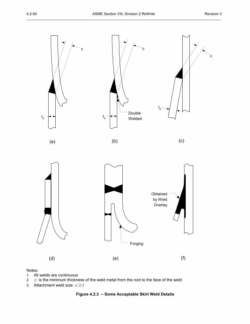
5) For attachment of support skirts or other supports involving similar attachment orientation, in addition to the weld types of paragraphs 4.2.5.6.e.3 and 4.2.5.6.e.4, welds of greater effective throat dimension than 90 deg fillet welds, as obtained by increased leg dimension or angle and
4.2-6 ASME Section VIII, Division 2 ReWrite Revision 3 _______________________________________________________________________________________________
bevel of parts joined, may be used where the effective throat is at (see Figure 4.2.3); however, the limitation on thickness in paragraph 4.2.5.6.e.2 shall apply.
f) Attachment Welds To Pressure Parts of Material Types 2 and 3 (see Table 4.2.3) � Welds attaching nonpressure parts or stiffeners to pressure parts shall be one of the following:
1) Except as permitted in paragraphs 4.2.5.6.f.2, fillet welds are permissible only for seal welds or for lightly loaded attachments with a weld size not over 10 mm (0.375 in.) leg dimension and shall not be located closer than sRt from a gross structural discontinuity.
2) For materials SA-333 Grade 8, SA-334 Grade 8, SA-353, SA-522, SA-553, and SA-645, fillet welds are permissible, provided that the fillet weld leg dimension does not exceed 13 mm (0.5 in.) and the weld is not closer than sRt from another gross structural discontinuity.
3) A partial penetration weld plus fillet weld; limited to the attachment of parts not exceeding 19 mm (0.75 in.) in thickness.
4) A full penetration groove weld plus a fillet weld on each side.
5) Full penetration butts weld (see paragraph 4.2.5.6.e.4 for boss requirements).
6) For attachment of support skirts or other supports involving similar attachment orientation, in addition to welds permitted by paragraph 4.2.5.6.f.5 above, welds of greater effective throat dimension than 90 deg fillet welds may be used where the throat is a minimum of at (see Figure 4.2.3). The details in this figure are limited to attachment of parts not exceeding 19 mm (0.75 in.) in thickness unless the attachment weld is double welded.
g) Stress Values For Weld Material � Attachment weld strength shall be based on the nominal weld area and the design stress intensity values in Annex 3.A for the weaker of the two materials joined, multiplied by the reduction factors, rW , shown below.
1) Full penetration butt or groove welds � 0.75rW = ; the nominal weld area is the depth of the weld times the length of weld.
2) Partial penetration groove or partial penetration groove plus fillet welds � 0.75rW = ; the nominal weld area is:
i) Groove welds � the depth of penetration times the length of weld.
ii) Groove welds with fillet welds � the combined throat and depth of penetration, exclusive of reinforcement, times the length of weld.
iii) Fillet welds � 0.5rW = ; the nominal weld area is the throat area.
h) Weld Overlay And Clad Construction
1) Attachments may be welded directly to weld overlay deposits without restriction.
2) For clad construction, attachment welds may be made directly to the cladding based on consideration of the degree of assurance of the lining bond and the desired reliability of performance in service. As an alternative, local regions of weld overlay can be located within the cladding to provide an attachment location.
3) For other types of applied linings, attachments should be made directly to the base metal unless an analysis, tests, or both can be performed to establish the adequacy and reliability of an attachment made directly to the lining. Note that successful experience with similar linings in comparable service may provide a basis for judgment.
i) PWHT Requirements � For heat treatment after welding, the fabrication requirements of the vessel base metal apply.
Revision 3 ASME Section VIII, Division 2 Rewrite 4.2-7 ______________________________________________________________________________________________ j) Evaluation Of Need For Fatigue Analysis � In applying the fatigue screening analysis in paragraph
5.5.2, fillet welds and non-full-penetration welds shall be considered to be nonintegral attachments, except that the following welds need not be considered because of the limitations of their use:
1) Welds covered by paragraphs 4.2.5.6.c, 4.2.5.6.e.1, 4.2.5.6.f.1 and 4.2.5.6.f.2.
2) Welds covered by paragraphs 4.2.5.6.e.5 and 4.2.5.6.f.6 may be considered integral.
4.2.5.7 Special Limitations for Joints In Quenched and Tempered High Strength Steels
a) In vessels and vessel parts constructed of quenched and tempered high strength steels (see Table 3.A.4) except as permitted in paragraph 4.2.5.7.b, all joints of Categories A, B, and C, and all other welded joints between parts of the pressure containing enclosure that are not defined by the category designation shall be Type No.1.
1) If the shell plate thickness is 51 mm (2 in.) or less, then all Category D welds shall be Type No. 1 in accordance with Table 4.2.13.
2) If the shell plate thickness is greater than 51 mm (2 in.), then the weld detail may be as permitted for nozzles in Table 4.2.10 or Table 4.2.13.
b) For materials SA-333 Grade 8, SA-334. Grade 8, SA-353, SA-522, SA-553, and SA-645 the weld joints of shall be as follows:
1) All joints of Category A shall be Type No.1.
2) All joints of Category B shall be Type No.1 or Type No.2.
3) All joints of Category C shall be full penetration welds extending through the entire section at the joint.
4) All joints of Category D attaching a nozzle neck to the vessel wall and to a reinforcing pad, if used, shall be full penetration groove welds.
4.2.5.8 Tube-To-Tubesheet Welds Requirements for tube-to-tubesheet welds are given in paragraph 4.18.
4.2.6 Nomenclature a is a geometry parameter used to determine the length requirements for a thickness transition
or a required weld size, applicable. b is a geometry parameter used to determine the length requirements for a thickness transition
or a required weld size, applicable. c is a weld size parameter R is the mean radius of the shell
at is the thickness of the attached member
ct is the throat dimension of a corner weld
et is the thickness of the reinforcing element
ht is the nominal thickness of the head
nt is the nominal thickness of the shell or nozzle, as applicable
pt is the minimum distance from the outside surface of a flat head to the edge of the weld preparation.
pipet is the minimum wall thickness of the connecting pipe
rt is the required thickness of the shell in accordance with the requirements of this Division
st is the nominal thickness of the shell
wt is the depth of penetration of the weld

4.2-8 ASME Section VIII, Division 2 ReWrite Revision 3 _______________________________________________________________________________________________
xt is two times the thickness 0g (see paragraph 4.16) when the design is calculated as an integral flange or two times the nozzle thickness of the shell nozzle wall required for internal pressure when the design is calculated as a loose flange, but in no case less than 6 mm (0.25 in.).
T is the minimum thickness of a flat head, cover, flange, or tubesheet, as applicable

Revision 3 ASME Section VIII, Division 2 Rewrite 4.2-9 ______________________________________________________________________________________________
4.2.7 Tables
4.2-10 ASME Section VIII, Division 2 ReWrite Revision 3 _______________________________________________________________________________________________
Table 4.2.1 � Definition Of Weld Categories Weld
Category Description
A • Longitudinal welded joints within the main shell, communicating chambers (1), transitions in diameter, or nozzles
• Any welded joint within a sphere, within a formed or flat head, or within the side plates (2) of a flat-sided vessel
• Circumferential welded joints connecting hemispherical heads to main shells, to transitions in diameter, to nozzles, or to communicating chambers.
B • Circumferential welded joints within the main shell, communicating chambers (1), nozzles or transitions in diameter including joints between the transition and a cylinder at either the large or small end
• Circumferential welded joints connecting formed heads other than hemispherical to main shells, to transitions in diameter, to nozzles, or to communicating chambers.
C • Welded joints connecting flanges, Van Stone laps, tubesheets or flat heads to main shell, to formed heads, to transitions in diameter, to nozzles, or to communicating chambers (1)
• Any welded joint connecting one side plate (2) to another side plate of a flat-sided vessel.
D • Welded joints connecting communicating chambers (1) or nozzles to main shells, to spheres, to transitions in diameter, to heads, or to flat-sided vessels
• Welded joints connecting nozzles to communicating chambers (1) (for nozzles at the small end of a transition in diameter see Category B).
E • Welded joints attaching nonpressure parts and stiffeners
Notes:
1. Communicating chambers are defined as appurtenances to the vessel that intersect the shell or heads of a vessel and form an integral part of the pressure containing enclosure, e.g., sumps.
2. Side plates of a flat-sided vessel are defined as any of the flat plates forming an integral part of the pressure containing enclosure.

Revision 3 ASME Section VIII, Division 2 Rewrite 4.2-11 ______________________________________________________________________________________________
4.2-12 ASME Section VIII, Division 2 ReWrite Revision 3 _______________________________________________________________________________________________
Table 4.2.2 � Definition Of Weld Joint Types Weld Joint
Type Description
1 Butt joints produced by double welding or by other means which produce the same quality of deposited weld metal on both inside and outside weld surfaces. Welds using backing strips which remain in place do not qualify as Type No.1 butt joints.
2 Butt joints produced by welding from one side with a backing strip that remains in place.
3 Butt joints produced by welding from one side without a backing strip.
7 Corner joints made with full penetration welds with or without cover fillet welds
8 Angle joints made with a full penetration weld where the cone half-apex angle exceeds 30 degrees
9 Corner joints made with partial penetration welds with or without cover fillet welds
10 Fillet welds
Revision 3 ASME Section VIII, Division 2 Rewrite 4.2-13 ______________________________________________________________________________________________
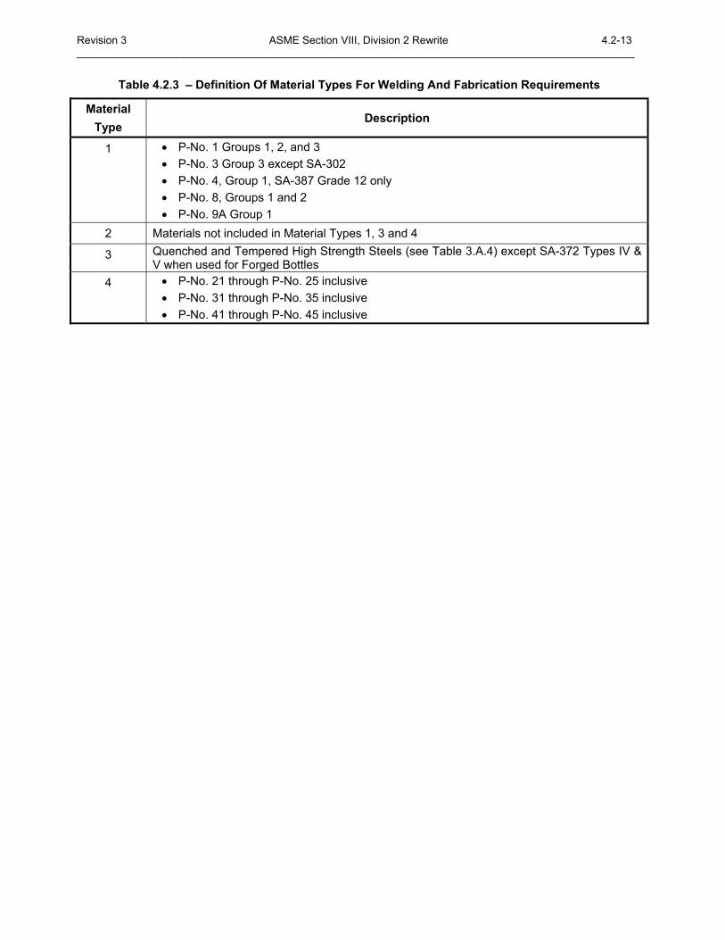
Table 4.2.3 � Definition Of Material Types For Welding And Fabrication Requirements Material
Type Description
1 • P-No. 1 Groups 1, 2, and 3 • P-No. 3 Group 3 except SA-302 • P-No. 4, Group 1, SA-387 Grade 12 only • P-No. 8, Groups 1 and 2 • P-No. 9A Group 1
2 Materials not included in Material Types 1, 3 and 4
3 Quenched and Tempered High Strength Steels (see Table 3.A.4) except SA-372 Types IV & V when used for Forged Bottles
4 • P-No. 21 through P-No. 25 inclusive • P-No. 31 through P-No. 35 inclusive • P-No. 41 through P-No. 45 inclusive

4.2-14 ASME Section VIII, Division 2 ReWrite Revision 3 _______________________________________________________________________________________________
Revision 3 ASME Section VIII, Division 2 Rewrite 4.2-15 ______________________________________________________________________________________________
Table 4.2.4 � Acceptable Weld Joints For Shell Seams
Detail Joint Type
Joint Category Design Notes Figure
1 1 A,B,C,D
2 2 B
3 3 B
4 1 A,B,C,D
b
a
WeldTaper EitherInside or Outside
5 1 A,B,C,D a
b
6 1 A,B,C,D
• If 3a b≥ • The length of the taper, a , may
include the weld
a
b
Weld
7 1 B • The weld bevel is shown for illustration only
• 1 max 0.8 ,rn pipet t t ≥
• 30α ≤ ° • ,14 18.5β β° ≤ ≤ ° • r, 6 mm (0.25 in.) min. radius
r
trn
α
tn
4.2-16 ASME Section VIII, Division 2 ReWrite Revision 3 _______________________________________________________________________________________________
Table 4.2.4 � Acceptable Weld Joints For Shell Seams
Detail Joint Type
Joint Category Design Notes Figure
8 1 B • 1 max 0.8 ,rn pipet t t ≥
• 30α ≤ ° • ,14 18.5β β° ≤ ≤ ° • r, 6 mm (0.25 in.) min. radius tpipe
β
r
trn
α
tn
αβ
r
9 1 B • 030α ≤ • see paragraph 4.2.5.3.f
10 8 B • 030α > CL
tv
tc
a
11 1 B • 030α ≤ • see paragraph 4.2.5.3.f
12 8 B • 030α >
CL
tc
a
tv

Revision 3 ASME Section VIII, Division 2 Rewrite 4.2-17 ______________________________________________________________________________________________
4.2-18 ASME Section VIII, Division 2 ReWrite Revision 3 _______________________________________________________________________________________________
Table 4.2.5 � Acceptable Weld Joints For Formed Heads
Detail Joint Type
Joint Category Design Notes Figure
1 1 A,B ts
th
2 1 A,B
thts
toff
b
Thinner Part Tangent Line
a
3 1 A,B
• 3a b≥ when ht exceeds st .
• ( )0.5off h st t t≤ −
• The skirt minimum length is [ ]min 3 , 38 (1.5 )ht mm in except
when necessary to provide the required taper length
• If 1.25h st t≤ , then the length of the skirt shall be sufficient for any required taper
• The length of the taper a may include the width of the weld.
• The shell plate center line may be on either side of the head plate center line
thb
ts
toff
Thinner Part Tangent Line
a
4 1 A,B • 3a b≥
• ( )0.5off h st t t≤ −
• The length of the taper a may include the width of the weld.
• The shell plate center line may be on either side of the head plate center line
Thinner Part
b
th
toff
ts a
Revision 3 ASME Section VIII, Division 2 Rewrite 4.2-19 ______________________________________________________________________________________________
Table 4.2.5 � Acceptable Weld Joints For Formed Heads
Detail Joint Type
Joint Category Design Notes Figure
5 1 A,B
Thinner Part
toffth
ts ab
6 1 A,B • Butt weld and fillet weld, if used,
shall be designed to take a shear load at 1.5 times the design differential pressure
• [ ]min 2 , 25 (1 )ha t mm in≥
• b, 13 mm (0.5 in.) minimum • The shell thicknesses 1st and 2st
may be different • ,15 20α α° ≤ ≤ °
th
Seal Or Fillet Weld
Butt Weld
Tangent Point
α
aab
ts2ts1
ID
7 1 A,B • 1 22r r≥
• [ ]2 min ,s hr t t≥ Forged Part
r2
th
r1
ts

4.2-20 ASME Section VIII, Division 2 ReWrite Revision 3 _______________________________________________________________________________________________
Revision 3 ASME Section VIII, Division 2 Rewrite 4.2-21 ______________________________________________________________________________________________
Table 4.2.6 � Acceptable Weld Joints For Unstayed Flat Heads, Tubesheets Without A Bolting Flange, And Side Plates of Rectangular Pressure Vessels
Detail Joint Type
Joint Category Design Notes Figure
1 7 C • 2 sa t≥
• w st t≥ tstwa
2 7 C • 2 sa b t+ ≥
• w st t≥
• [ ]min , 6 (0.25 )p st t mm in≥
• The dimension b is produced by the weld preparation and shall be verified after fit-up and before welding
tstwa
b
tp
3 7 C • 2 sa b t+ ≥
• sa t≥
• [ ]min , 6 (0.25 )p st t mm in≥
• The dimension b is produced by the weld preparation and shall be verified after fit-up and before welding
tsa
b
tp
4 7 C • 2 sa b t+ ≥
• sa t≥
• [ ]min , 6 (0.25 )p st t mm in≥
• The dimension b is produced by the weld preparation and shall be verified after fit-up and before welding
tsa
b
tp
4.2-22 ASME Section VIII, Division 2 ReWrite Revision 3 _______________________________________________________________________________________________
Table 4.2.6 � Acceptable Weld Joints For Unstayed Flat Heads, Tubesheets Without A Bolting Flange, And Side Plates of Rectangular Pressure Vessels
Detail Joint Type
Joint Category Design Notes Figure
5 7 C • 2 sa t≥ ts
a
Backing StripMay Be Used
6 7 C • 2 sa b t+ ≥
• sa t≥
• The dimension b is produced by the weld preparation and shall be verified after fit-up and before welding
tsa
b
7 7 C • 2 sa b t+ ≥
• 0b = is permissible • The dimension b is produced by
the weld preparation and shall be verified after fit-up and before welding
ts
a
bThis Weld Metal May BeDeposited BeforeCompleting the Joint
8 7 C • 2 sa b t+ ≥
• 0b = is permissible • The dimension b is produced by
the weld preparation and shall be verified after fit-up and before welding
ts
a
bThis Weld Metal May BeDeposited BeforeCompleting the Joint

Revision 3 ASME Section VIII, Division 2 Rewrite 4.2-23 ______________________________________________________________________________________________
4.2-24 ASME Section VIII, Division 2 ReWrite Revision 3 _______________________________________________________________________________________________
Table 4.2.7 � Acceptable Weld Joints With Butt Weld Hubs
Detail Joint Type
Joint Category Design Notes Figure
1 1 C • 10 (0.375 .)r mm in≥ for
38 (1.5 )st mm in≤
• [ ]min 0.25 , 19 (0.75 )sr t mm in≥
for 38 (1.5 )st mm in> r
Tension Test Specimen
ts
2 1 C • 10 (0.375 .)r mm in≥ for
38 (1.5 )st mm in≤
• [ ]min 0.25 , 19 (0.75 )sr t mm in≥
for 38 (1.5 )st mm in>
• [ ]max ,s re t T≥ but need not exceed
r
Tension Test Specimen
ts
e
3 1 C • [ ]max 1.5 , 19 (0.75 )sh t mm in=
but need not exceed 51 (2 )mm inTension Test Specimen
ts
h

Revision 3 ASME Section VIII, Division 2 Rewrite 4.2-25 ______________________________________________________________________________________________
4.2-26 ASME Section VIII, Division 2 ReWrite Revision 3 _______________________________________________________________________________________________
Table 4.2.8 � Acceptable Weld Joints For Attachment Of Tubesheets With A Bolting Flange
Detail Joint Type
Joint Category Design Notes Figure
1 7 C • 2 sa t≥
• The dimension b is produced by the weld preparation and shall be verified after fit-up and before welding
• [ ]min 0.7 ,1.4s rc t t≥
tsa
Backing StripMay Be Used
c
2 7 C • 2 sa b t+ ≥
• The dimension b is produced by the weld preparation and shall be verified after fit-up and before welding
• [ ]min 0.7 ,1.4s rc t t≥
ts
a
b
c
3 7 C • 2 sa b t+ ≥
• The dimension b is produced by the weld preparation and shall be verified after fit-up and before welding
• [ ]min 0.7 ,1.4s rc t t≥
tsa
b
This weld metal maybe deposited beforecompleting the joint
c
Revision 3 ASME Section VIII, Division 2 Rewrite 4.2-27 ______________________________________________________________________________________________
Table 4.2.8 � Acceptable Weld Joints For Attachment Of Tubesheets With A Bolting Flange
Detail Joint Type
Joint Category Design Notes Figure
4 7 C • 2 sa b t+ ≥
• 0b = is permissible • The dimension b is produced by
the weld preparation and shall be verified after fit-up and before welding
• [ ]min 0.7 ,1.4s rc t t≥
ts
a
b
c
5 10 C • 1 2a a a= +
• 1 20.5a a≥ and 1 22a a≤
• [ ]min 0.7 ,1.4s rc t t≥ where rt is the required thickness of the shell in accordance with the requirements of this Division
tsa1
c
a2
6 7 C • 3 na t≥
• [ ]min ,n xc t t≥
• Backing strip may be removed after welding tn
a
Backing Strip MayBe Used If Joint IsNot Welded FromBoth Sides
c

4.2-28 ASME Section VIII, Division 2 ReWrite Revision 3 _______________________________________________________________________________________________
Table 4.2.8 � Acceptable Weld Joints For Attachment Of Tubesheets With A Bolting Flange
Detail Joint Type
Joint Category Design Notes Figure
7 7 C • 3 na b t+ ≥
• [ ]min ,n xc t t≥
• [ ]min , 6 (0.25 )p nt t mm in≥
tn
a
c
tp b

Revision 3 ASME Section VIII, Division 2 Rewrite 4.2-29 ______________________________________________________________________________________________

4.2-30 ASME Section VIII, Division 2 ReWrite Revision 3 _______________________________________________________________________________________________
Table 4.2.9 � Acceptable Weld Joints For Flange Attachments
Detail Joint Type
Joint Category Design Notes Figure
1 10 C • 0.7c nt t≥
• 6 (0.25 )nc t mm in≥ + maximum
c tctc
T
tn
2 10 C • 0.7c nt t≥
• 6 (0.25 )nc t mm in≥ + maximum
c tc
T
tn
3 7 C • 0.7c nt t≥
• 0.5c t≥ maximum
c tc
T
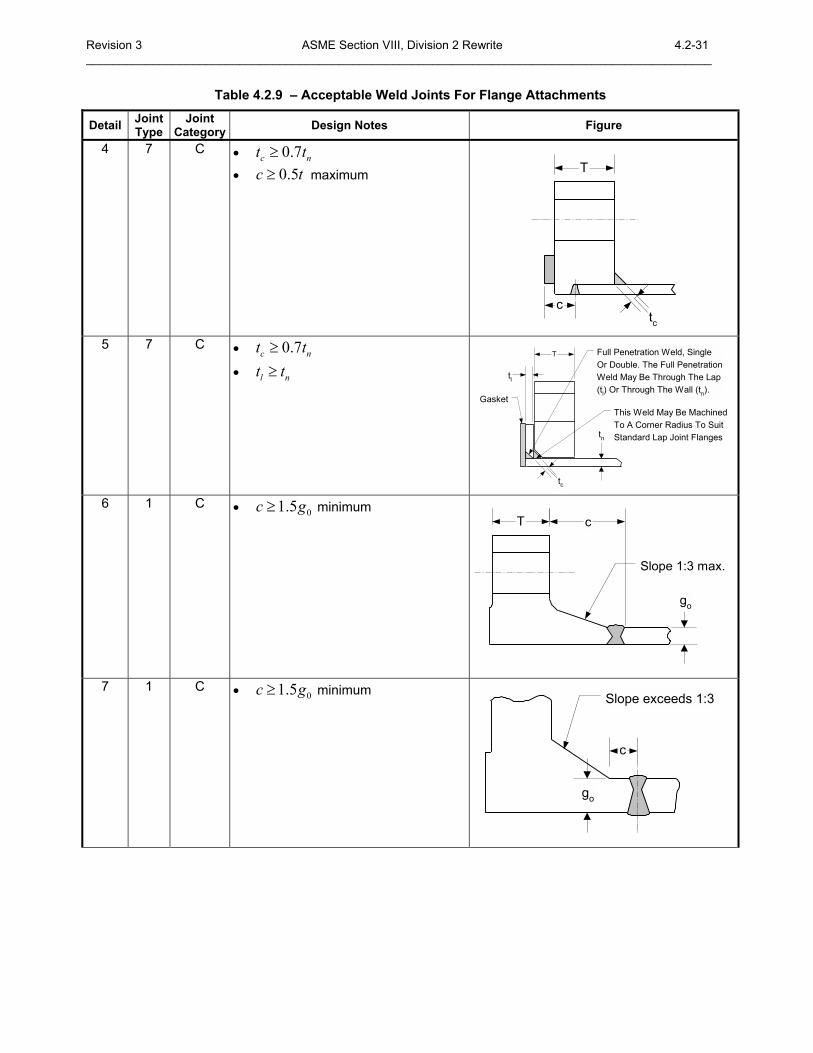
Revision 3 ASME Section VIII, Division 2 Rewrite 4.2-31 ______________________________________________________________________________________________
Table 4.2.9 � Acceptable Weld Joints For Flange Attachments
Detail Joint Type
Joint Category Design Notes Figure
4 7 C • 0.7c nt t≥
• 0.5c t≥ maximum
ctc
T
5 7 C • 0.7c nt t≥
• l nt t≥
tc
tl
Gasket
tn
Full Penetration Weld, SingleOr Double. The Full PenetrationWeld May Be Through The Lap(tl) Or Through The Wall (tn).
This Weld May Be MachinedTo A Corner Radius To SuitStandard Lap Joint Flanges
T
6 1 C • 01.5c g≥ minimum
go
Slope 1:3 max.
cT
7 1 C • 01.5c g≥ minimum
go
Slope exceeds 1:3
c
4.2-32 ASME Section VIII, Division 2 ReWrite Revision 3 _______________________________________________________________________________________________
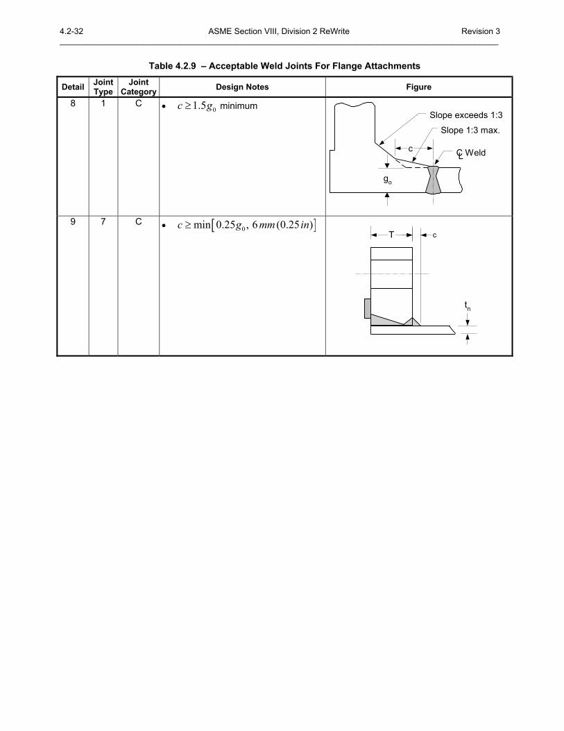
Table 4.2.9 � Acceptable Weld Joints For Flange Attachments
Detail Joint Type
Joint Category Design Notes Figure
8 1 C • 01.5c g≥ minimum
go
Slope exceeds 1:3
c C WeldL
Slope 1:3 max.
9 7 C • [ ]0min 0.25 , 6 (0.25 )c g mm in≥ T
tn
c

Revision 3 ASME Section VIII, Division 2 Rewrite 4.2-33 ______________________________________________________________________________________________
4.2-34 ASME Section VIII, Division 2 ReWrite Revision 3 _______________________________________________________________________________________________
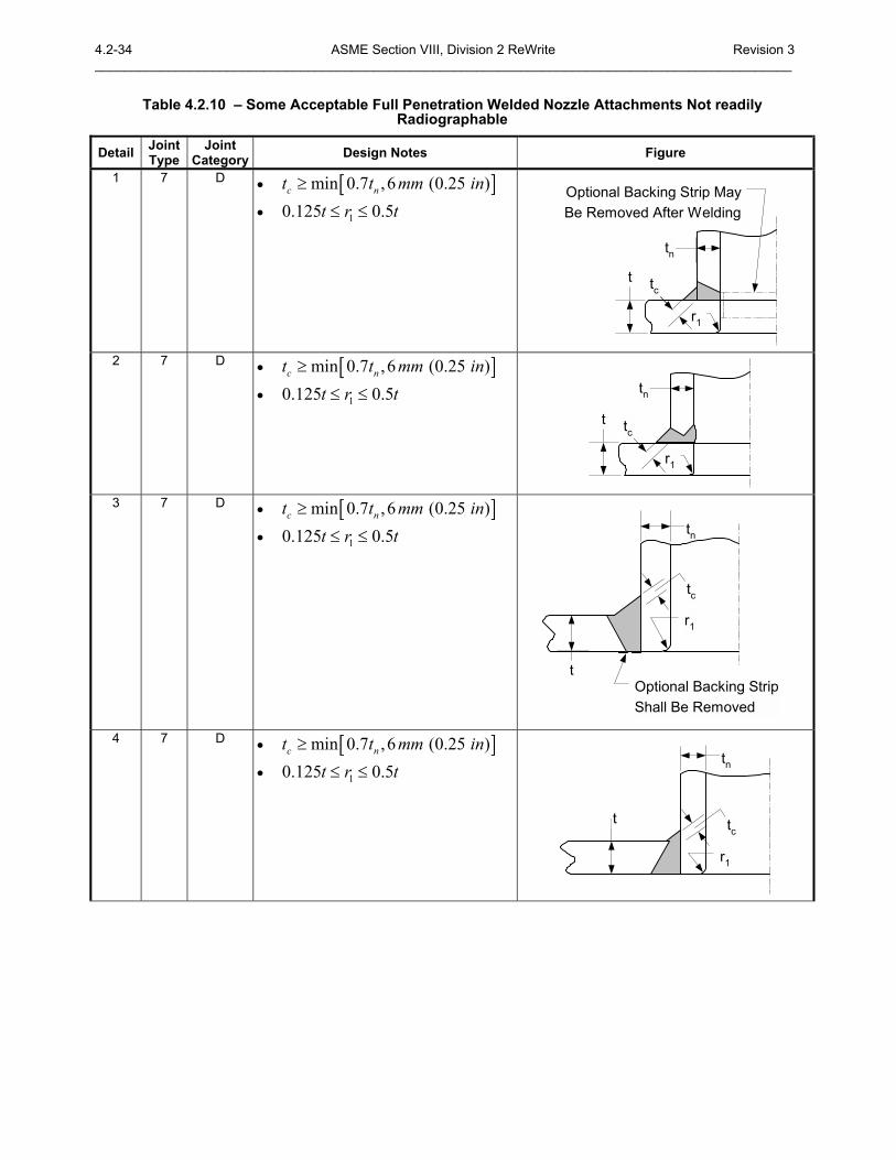
Table 4.2.10 � Some Acceptable Full Penetration Welded Nozzle Attachments Not readily Radiographable
Detail Joint Type
Joint Category Design Notes Figure
1 7 D • [ ]min 0.7 ,6 (0.25 )c nt t mm in≥
• 10.125 0.5t r t≤ ≤ Optional Backing Strip MayBe Removed After Welding
r1
t
tn
tc
2 7 D • [ ]min 0.7 ,6 (0.25 )c nt t mm in≥
• 10.125 0.5t r t≤ ≤
r1
t
tn
tc
3 7 D • [ ]min 0.7 ,6 (0.25 )c nt t mm in≥
• 10.125 0.5t r t≤ ≤ tn
r1
tOptional Backing StripShall Be Removed
tc
4 7 D • [ ]min 0.7 ,6 (0.25 )c nt t mm in≥
• 10.125 0.5t r t≤ ≤ tn
r1
t tc
Revision 3 ASME Section VIII, Division 2 Rewrite 4.2-35 ______________________________________________________________________________________________
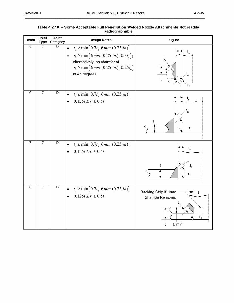
Table 4.2.10 � Some Acceptable Full Penetration Welded Nozzle Attachments Not readily Radiographable
Detail Joint Type
Joint Category Design Notes Figure
5 7 D • [ ]min 0.7 ,6 (0.25 )c nt t mm in≥
• [ ]3 min 6 (0.25 .), 0.5 nr mm in t≥ ; alternatively, an chamfer of
[ ]3 min 6 (0.25 .), 0.25 nr mm in t≥at 45 degrees
t
tntc
r3
tcr3
6 7 D • [ ]min 0.7 ,6 (0.25 )c nt t mm in≥
• 10.125 0.5t r t≤ ≤
t
r1
tn
tc
7 7 D • [ ]min 0.7 ,6 (0.25 )c nt t mm in≥
• 10.125 0.5t r t≤ ≤ tn
r1
t tc
8 7 D • [ ]min 0.7 ,6 (0.25 )c nt t mm in≥
• 10.125 0.5t r t≤ ≤
t
r1
tn
tc
tn min.
Backing Strip If UsedShall Be Removed
4.2-36 ASME Section VIII, Division 2 ReWrite Revision 3 _______________________________________________________________________________________________
Table 4.2.10 � Some Acceptable Full Penetration Welded Nozzle Attachments Not readily Radiographable
Detail Joint Type
Joint Category Design Notes Figure
9 7 D • [ ]min 0.7 ,6 (0.25 )c nt t mm in≥
• 10.125 0.5t r t≤ ≤
• 2 19 (0.75 .)r mm in≥
• 4 6 (0.25 .)r mm in≥
tn
A
A
r2
r1
ttr1
r2
Section A-A
Sections Perpendicular and Parallel to theCylindrical Vessel Axis
r4tc
tn
tc
tc
r1

Revision 3 ASME Section VIII, Division 2 Rewrite 4.2-37 ______________________________________________________________________________________________
4.2-38 ASME Section VIII, Division 2 ReWrite Revision 3 _______________________________________________________________________________________________
Table 4.2.11 � Some Acceptable Pad Welded Nozzle Attachments And Other Connections To Shells
Detail Joint Type
Joint Category Design Notes Figure
1 7 D • [ ]min 0.7 ,6 (0.25 )c nt t mm in≥
• [ ]1 min 0.6 , 0.6f et t t≥
• [ ]3 min 6 (0.25 .), 0.5 nr mm in t≥ ; alternatively, an chamfer of
[ ]3 min 6 (0.25 .), 0.25 nr mm in t≥at 45 degrees
te
tntc
t
tc
tf1
r3
2 7 D • [ ]min 0.7 ,6 (0.25 )c nt t mm in≥
• [ ]1 min 0.6 , 0.6f et t t≥
• 10.125 0.5t r t≤ ≤
te
tntc
t
tf1
r1
3 7 D • [ ]min 0.7 ,6 (0.25 )c nt t mm in≥
• [ ]1 min 0.6 , 0.6f et t t≥
• [ ]3 min 6 (0.25 .), 0.5 nr mm in t≥ ; alternatively, an chamfer of
[ ]3 min 6 (0.25 .), 0.25 nr mm in t≥at 45 degrees
te
tntc
t
tf1
r3
te tf1tc
4 10 D • [ ]2 min 0.7 , 0.7f et t t≥
tf2
t
tf2
tew
Revision 3 ASME Section VIII, Division 2 Rewrite 4.2-39 ______________________________________________________________________________________________
Table 4.2.11 � Some Acceptable Pad Welded Nozzle Attachments And Other Connections To Shells
Detail Joint Type
Joint Category Design Notes Figure
5 7 D • [ ]2 min 0.7 , 0.7f et t t≥
• 10.125 0.5t r t≤ ≤
t
te
tf2
r1
w

4.2-40 ASME Section VIII, Division 2 ReWrite Revision 3 _______________________________________________________________________________________________
Revision 3 ASME Section VIII, Division 2 Rewrite 4.2-41 ______________________________________________________________________________________________ Table 4.2.12 � Some Acceptable Fitting Type Welded Nozzle Attachments And Other Connections To
Shells
Detail Joint Type
Joint Category Design Notes Figure
1 7 D • [ ]min 0.7 ,6 (0.25 )c nt t mm in≥
tc
CL
2 7 D • [ ]min 0.7 ,6 (0.25 )c nt t mm in≥
tc
tc
CL
3 7 D • [ ]min 0.7 ,6 (0.25 )c nt t mm in≥
tc
CL
4 10 D • [ ]min 0.7 ,6 (0.25 )c nt t mm in≥
• [ ]2 min 0.7 , 0.7f et t t≥
tf2
tf2tet
5 9 D • Limited to DIN 80 (NPS 3)
maximum • The groove weld gt shall not be
less than the thickness of Schedule 160
• tc, 6 mm (0.25 in.) minimum tc
tg

4.2-42 ASME Section VIII, Division 2 ReWrite Revision 3 _______________________________________________________________________________________________
Revision 3 ASME Section VIII, Division 2 Rewrite 4.2-43 ______________________________________________________________________________________________
Table 4.2.13 � Acceptable Welded Nozzle Attachments That Are Readily Radiographable
Detail Joint Type
Joint Category Design Notes Figure
1 1 D • 10.125 0.5t r t≤ ≤
• [ ]2 min 0.25 ,19 (0.75 )nr t mm in≥tn
t
r2
r1
a
31
2 1 D • 10.125 0.5t r t≤ ≤
• [ ]2 min 0.25 ,19 (0.75 )nr t mm in≥
t
r1
tnr2
r245° Max.
30° Max.
1.5t min.
3 1 D • 10.125 0.5t r t≤ ≤
• [ ]2 min 0.25 ,19 (0.75 )nr t mm in≥
• 3 4 0.2t t t+ ≤
• 1 2 18.5a a Degree+ ≤
tnr2
t3
t
30° min.13 mm (0.5 in.)
Min.
t4
r2a1
a2
4 1 D • 10.125 0.5t r t≤ ≤
• [ ]2 min 0.25 ,19 (0.75 )nr t mm in≥
tntn
A
A
45° Max.
r2
30° Max.
r2
r1
tt
r1
45° Max.r2
r2
18.5° Max.30° Max.
Section A-A
Sections Perpendicular and Parallel to theCylindrical Vessel Axis
0.2t max
4.2-44 ASME Section VIII, Division 2 ReWrite Revision 3 _______________________________________________________________________________________________
Table 4.2.13 � Acceptable Welded Nozzle Attachments That Are Readily Radiographable
Detail Joint Type
Joint Category Design Notes Figure
5 1 D • [ ]2 min 0.25 ,19 (0.75 )nr t mm in≥ tn
t r2
r2
6 1 D • [ ]2 min 0.25 ,19 (0.75 )nr t mm in≥
tnt r2
r2
Optional Backing StripShall Be Removed

Revision 3 ASME Section VIII, Division 2 Rewrite 4.2-45 ______________________________________________________________________________________________
4.2-46 ASME Section VIII, Division 2 ReWrite Revision 3 _______________________________________________________________________________________________
Table 4.2.14 � Some Acceptable Partial Penetration Nozzle Attachments
Detail Joint Type
Joint Category Design Notes Figure
1 9 D • [ ]min 0.7 ,6 (0.25 )c nt t mm in≥
• 1.25w nt t≥
tn3 mm (0.0625 in.)
recess
tw
tc
2 9 D • [ ]min 0.7 ,6 (0.25 )c nt t mm in≥
• 1.25w nt t≥ tn
3 mm (0.0625 in.) recess
Section A-A
twtctn
tc
A
A
3 9 D • 10.125 0.5t r t≤ ≤
•
max defined as follows:0.25 , 250.51 , 25 1020.76 , 1020.01 , 10.02 , 1 40.03 , 4
o
o
o
o
o
o
Cmm D mmmm mm D mmmm D mmin D inin in D inin D in
≤< ≤
>≤< ≤>
Cmax
tnDo
Outside
r1
1.25tn min.t
4 9 D • [ ]2 min 0.7 , 0.7f et t t≥
• 10.125 0.5t r t≤ ≤
•
max defined as follows:0.25 , 250.51 , 25 1020.76 , 1020.01 , 10.02 , 1 40.03 , 4
o
o
o
o
o
o
Cmm D mmmm mm D mmmm D mmin D inin in D inin D in
≤< ≤
>≤< ≤>
Cmax
tnDo
r1
1.25tn min.
w
te
ttf2
Revision 3 ASME Section VIII, Division 2 Rewrite 4.2-47 ______________________________________________________________________________________________
Table 4.2.14 � Some Acceptable Partial Penetration Nozzle Attachments
Detail Joint Type
Joint Category Design Notes Figure
5 9 D • [ ]2 min 0.7 , 0.7f et t t≥
• 10.125 0.5t r t≤ ≤
•
max defined as follows:0.25 , 250.51 , 25 1020.76 , 1020.01 , 10.02 , 1 40.03 , 4
o
o
o
o
o
o
Cmm D mmmm mm D mmmm D mmin D inin in D inin D in
≤< ≤
>≤< ≤>
Cmax
tnDo
r1
w
te
t
tf2
1.25tn
6 9 D • 1 2 1.25t t t+ ≥
• [ ]1 min 0.7 , 6 (0.25 )rt t mm in≥
• [ ]2 min 0.7 , 6 (0.25 )rt t mm in≥
t
tn
t1
t2
7 9 D • [ ]min 0.7 ,6 (0.25 )c nt t mm in≥
• 1 2 1.25t t t+ ≥
• [ ]1 min 0.7 , 6 (0.25 )rt t mm in≥
• [ ]2 min 0.7 , 6 (0.25 )rt t mm in≥
t
tn
t1
tc
t2
4.2-48 ASME Section VIII, Division 2 ReWrite Revision 3 _______________________________________________________________________________________________
4.2.8 Figures
C B
B
A
A
A D
AB
D
A
B
A A
B
α
C
A
A D
B
D
A
C
C
DB
A C
Figure 4.2.1 � Weld Joint Locations Typical Of categories A, B, C, and D
Revision 3 ASME Section VIII, Division 2 Rewrite 4.2-49 ______________________________________________________________________________________________
Continuous
A A
(a)
Continuous
A A
(b)
BB
Continuous Acceptable
Preferred
(c)
B
B
Continuous
A
A
Continuous
A
A
Continuous
(d) (e) (f)
Weld Buildup
Section A-A
3 mm (1/8 in) max.
ta
ta
a
t
b
t
Round CornersOn Pads
b
t
Round CornersOn Pads
b
Section B-B
Notes: 1. Attachment weld size: 0.25a t≥ and 0.5b t≥ 2. Vents holes shall be considered for continuously attached pads 3. For design (e) above, a minimum of 50% of the web must be welded, evenly spaced around the
circumference of the shell
Figure 4.2.2 � Some Bracket, Leg and Support Attachment Weld Details
4.2-50 ASME Section VIII, Division 2 ReWrite Revision 3 _______________________________________________________________________________________________
ta
c
ta
c
DoubleWelded
Forging
(a) (b) (c)
(d) (e) (f)
c
ta
Obtainedby WeldOverlay
Notes: 1. All welds are continuous 2. c is the minimum thickness of the weld metal from the root to the face of the weld 3. Attachment weld size: c t≥
Figure 4.2.3 � Some Acceptable Skirt Weld Details


![[Corus] Design of SHS Welded Joints](https://img.dokumen.tips/doc/110x75/577d1fe51a28ab4e1e918f6a/corus-design-of-shs-welded-joints.jpg)