Embed Size (px)
Citation preview
Power Systems
Farhad ShahniaSumedha RajakarunaArindam Ghosh Editors
Static Compensators (STATCOMs) in Power Systems

Power Systems

More information about this series at http://www.springer.com/series/4622
Farhad Shahnia • Sumedha RajakarunaArindam GhoshEditors
Static Compensators(STATCOMs) in PowerSystems
123

EditorsFarhad ShahniaDepartment of Electrical and ComputerEngineering
Curtin UniversityPerthAustralia
Sumedha RajakarunaDepartment of Electrical and ComputerEngineering
Curtin UniversityPerthAustralia
Arindam GhoshDepartment of Electrical and ComputerEngineering
Curtin UniversityPerthAustralia
ISSN 1612-1287 ISSN 1860-4676 (electronic)Power SystemsISBN 978-981-287-280-7 ISBN 978-981-287-281-4 (eBook)DOI 10.1007/978-981-287-281-4
Library of Congress Control Number: 2014957148
Springer Singapore Heidelberg New York Dordrecht London© Springer Science+Business Media Singapore 2015This work is subject to copyright. All rights are reserved by the Publisher, whether the whole or partof the material is concerned, specifically the rights of translation, reprinting, reuse of illustrations,recitation, broadcasting, reproduction on microfilms or in any other physical way, and transmissionor information storage and retrieval, electronic adaptation, computer software, or by similar ordissimilar methodology now known or hereafter developed.The use of general descriptive names, registered names, trademarks, service marks, etc. in thispublication does not imply, even in the absence of a specific statement, that such names are exemptfrom the relevant protective laws and regulations and therefore free for general use.The publisher, the authors and the editors are safe to assume that the advice and information in thisbook are believed to be true and accurate at the date of publication. Neither the publisher nor theauthors or the editors give a warranty, express or implied, with respect to the material containedherein or for any errors or omissions that may have been made.
Printed on acid-free paper
Springer Science+Business Media Singapore Pte Ltd. is part of Springer Science+Business Media(www.springer.com)
Preface
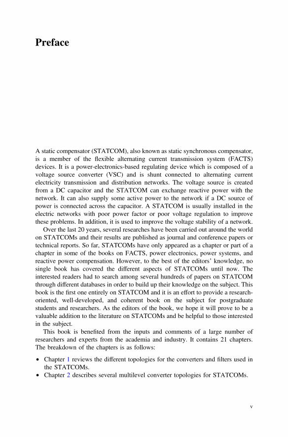
A static compensator (STATCOM), also known as static synchronous compensator,is a member of the flexible alternating current transmission system (FACTS)devices. It is a power-electronics-based regulating device which is composed of avoltage source converter (VSC) and is shunt connected to alternating currentelectricity transmission and distribution networks. The voltage source is createdfrom a DC capacitor and the STATCOM can exchange reactive power with thenetwork. It can also supply some active power to the network if a DC source ofpower is connected across the capacitor. A STATCOM is usually installed in theelectric networks with poor power factor or poor voltage regulation to improvethese problems. In addition, it is used to improve the voltage stability of a network.
Over the last 20 years, several researches have been carried out around the worldon STATCOMs and their results are published as journal and conference papers ortechnical reports. So far, STATCOMs have only appeared as a chapter or part of achapter in some of the books on FACTS, power electronics, power systems, andreactive power compensation. However, to the best of the editors’ knowledge, nosingle book has covered the different aspects of STATCOMs until now. Theinterested readers had to search among several hundreds of papers on STATCOMthrough different databases in order to build up their knowledge on the subject. Thisbook is the first one entirely on STATCOM and it is an effort to provide a research-oriented, well-developed, and coherent book on the subject for postgraduatestudents and researchers. As the editors of the book, we hope it will prove to be avaluable addition to the literature on STATCOMs and be helpful to those interestedin the subject.
This book is benefited from the inputs and comments of a large number ofresearchers and experts from the academia and industry. It contains 21 chapters.The breakdown of the chapters is as follows:
• Chapter 1 reviews the different topologies for the converters and filters used inthe STATCOMs.
• Chapter 2 describes several multilevel converter topologies for STATCOMs.
v
• Chapter 3 discusses the analysis and implementation of an 84-pulse STATCOM.• Chapter 4 presents the mathematical modeling of STATCOMs and control
algorithms for STATCOMs.• Chapter 5 discusses some control strategies for the STATCOMs.• Chapter 6 presents the robust nonlinear control method for the STATCOMs.• Chapter 7 describes the utilization of multiple reference frames for versatile
control of STATCOMs.• Chapter 8 presents the different control algorithms for multilevel STATCOMs.• Chapter 9 discusses the adaptive observer for capacitor voltages in multilevel
STATCOMs.• Chapter 10 presents different methods of modeling and control of STATCOMs.• Chapter 11 studies the STATCOM operation in steady state and dynamic modes
in abc framework.• Chapter 12 presents a load flow method considering the presence of STATCOM
in power systems.• Chapter 13 reviews different methods for optimal placement and sizing of
STATCOMs in power systems based on heuristic optimization techniques.• Chapter 14 discusses a multi-objective optimization technique to define the
optimal placement of STATCOMs in power systems against short-term voltageinstability.
• Chapter 15 demonstrates the application of STATCOM for increasing theavailable power transfer capability in transmission networks
• Chapter 16 presents the application of STATCOM for decentralized secondaryvoltage control in transmission networks.
• Chapter 17 provides an analysis for damping of subsynchronous oscillationswith the help of STATCOMs.
• Chapter 18 demonstrates the STATCOM application for mitigation of subsyn-chronous resonance in wind farms that are connected to series-compensatedtransmission lines.
• Chapter 19 introduces two case studies for the application of STATCOM onMexican power systems.
• Chapter 20 presents the stability analysis of STATCOM in distributionnetworks.
• Chapter 21 discusses the network protection systems in the presence ofSTATCOMs.
As the editors of the book, we would like to thank all the contributors for theirsupport and hard work. We also would like to thank the reviewers who providedvaluable comments to improve the quality of the book. Also, we thank the publisherSpringer for agreeing to publish this book. Last but not least, we would like to thank
vi Preface

our respective families—Farhad thanks his parents (Ali and Nahideh) and hisspouse (Negar), Sumedha thanks his spouse (Gayani) and Arindam thanks hisspouse (Supriya) for their encouragement and support.
September 2014 Farhad ShahniaSumedha Rajakaruna
Arindam Ghosh
Preface vii
Contents
1 Converter and Output Filter Topologies for STATCOMs . . . . . . . 1Ersan Kabalci
2 Multilevel Converter Topologies for STATCOMs . . . . . . . . . . . . . 35Anshuman Shukla and Alireza Nami
3 Analysis and Implementation of an 84-Pulse STATCOM . . . . . . . 83Antonio Valderrabano-Gonzalez, Juan M. Ramirez,Ruben Tapia-Olvera, Julio C. Rosas-Caro,Jose M. Lozano-Garcia and Juan Miguel Gonzalez-Lopez
4 Mathematical Modeling and Control Algorithmsof STATCOMs . . . . . . . . . . . . . . . . . . . . . . . . . . . . . . . . . . . . . . 111Boštjan Blažič, Leopold Herman, Ambrož Božičekand Igor Papič
5 STATCOM Control Strategies . . . . . . . . . . . . . . . . . . . . . . . . . . 147Dionisio Ramirez, Luis Carlos Herrero, Santiago de Pabloand Fernando Martinez
6 Robust Nonlinear Control of STATCOMs . . . . . . . . . . . . . . . . . . 187Yonghao Gui, Chunghun Kim, Youngseong Hanand Chung Choo Chung
7 Versatile Control of STATCOMs Using MultipleReference Frames . . . . . . . . . . . . . . . . . . . . . . . . . . . . . . . . . . . . 225Miguel Ochoa-Giménez, Aurelio García-Cerrada,Javier Roldán-Pérez, Juan L. Zamora-Macho,Pablo García-González and Emilo Bueno
ix
8 Control of Multilevel STATCOMs . . . . . . . . . . . . . . . . . . . . . . . . 265Javier Muñoz, Pedro Melín and José Espinoza
9 Adaptive Observer for Capacitor Voltages in MultilevelSTATCOMs . . . . . . . . . . . . . . . . . . . . . . . . . . . . . . . . . . . . . . . . 313J. de León Morales, M.F. Escalante and M.T. Mata-Jiménez
10 Modeling and Control of STATCOMs . . . . . . . . . . . . . . . . . . . . . 339Amit Kumar Jain and Aman Behal
11 Study of STATCOM in abc Framework . . . . . . . . . . . . . . . . . . . 371Juan M. Ramirez, Juan Miguel Gonzalez-Lopez,Julio C. Rosas-Caro, Ruben Tapia-Olvera,Jose M. Lozano and Antonio Valderrabano-Gonzalez
12 Modeling of STATCOM in Load Flow Formulation . . . . . . . . . . . 405Salah Kamel and Francisco Jurado
13 Optimal Placement and Sizing of STATCOM in PowerSystems Using Heuristic Optimization Techniques . . . . . . . . . . . . 437Reza Sirjani
14 Optimal Placement of STATCOMs Against Short-TermVoltage Instability . . . . . . . . . . . . . . . . . . . . . . . . . . . . . . . . . . . 477Yan Xu, Zhao Yang Dong and Kit Po Wong
15 STATCOM Application for Enhancement of AvailablePower Transfer Capability in Transmission Networks . . . . . . . . . 505Trapti Jain, Sri Niwas Singh and Suresh Chandra Srivastava
16 STATCOM Application for Decentralized SecondaryVoltage Control of Transmission Networks . . . . . . . . . . . . . . . . . 531Hasan Mehrjerdi, Serge Lefebvre and Maarouf Saad
17 Analysis and Damping of Subsynchronous OscillationsUsing STATCOM . . . . . . . . . . . . . . . . . . . . . . . . . . . . . . . . . . . . 557Nagesh Prabhu
18 STATCOM Application for Mitigation of SubsynchronousResonance in Wind Farms Connected to Series-CompensatedTransmission Lines . . . . . . . . . . . . . . . . . . . . . . . . . . . . . . . . . . . 595Akshaya Kumar Moharana and Rajiv K. Varma
x Contents
19 STATCOM on the Mexican Power Systems:Two Case Studies . . . . . . . . . . . . . . . . . . . . . . . . . . . . . . . . . . . . 661Miguel A. Olguín-Becerril, Esther Barrios-Martínezand César Ángeles-Camacho
20 Stability Analysis of STATCOM in Distribution Networks . . . . . . 687Juan Segundo-Ramírez, Aurelio Medina Ríos and Gerard Ledwich
21 Network Protection Systems Considering the Presenceof STATCOMs . . . . . . . . . . . . . . . . . . . . . . . . . . . . . . . . . . . . . . 715Premalata Jena and Ashok Kumar Pradhan
Contents xi
About the Editors
Farhad Shahnia received his Ph.D. in Electrical Engineering from QueenslandUniversity of Technology, Brisbane, Australia in 2011. Currently, he is a Lecturerof Power Engineering in Curtin University, Perth, Australia. His professionalexperience includes 3 years at Research Office-Eastern Azarbayjan Electric PowerDistribution Company, Tabriz, Iran. Prior to joining Curtin University, he was aresearch fellow in Queensland University of Technology, Brisbane, Australia. Hehas published five book chapters and over 80 research articles.
Sumedha Rajakaruna received his Ph.D. in Electrical Engineering from Uni-versity of Toronto, Ontario, Canada in 1993. Currently, he is a senior lecturer ofPower Engineering at Curtin University, Perth, Australia. Prior to joining CurtinUniversity in 2007, he was with University of Moratuwa, Sri Lanka from 1994 to2000 and with Nanyang Technological University, Singapore, from 2000 to 2007.He is the supervisor of more than ten Ph.D. graduates and has published two bookchapters and over 40 research articles.
Arindam Ghosh received his Ph.D. in Electrical Engineering from University ofCalgary, Canada in 1983. Currently, he is a Professor of Power Engineering atCurtin University, Perth, Australia. Prior to joining Curtin University in 2013, hewas with Indian Institute of Technology (IIT), Kanpur, India, from 1985 to 2006and with Queensland University of Technology, Brisbane, Australia from 2006 to2013. He is a fellow of INAE and IEEE. He is also an IEEE PES distinguishedlecturer. He is the supervisor of more than 30 Ph.D. graduates and has publishedtwo books, seven book chapters, and more than 350 research articles.
xiii
Reviewers
Akshaya Kumar Moharana, Powertech Labs Inc, CanadaAmit Kumar Jain, Intel Corporation, USAAntonio Valderrabano-Gonzalez, Universidad Panamericana, MexicoAnup Kumar Panda, National Institute of Technology-Rourkela, IndiaAurelio Garcia-Cerrada, Comillas Pontifical University, SpainBehrooz Vahidi, Amirkabir University of Technology, IranCesar Angeles-Camacho, Universidad Nacional Autónoma de México, MexicoChung Choo Chung, Hanyang University, Republic of KoreaDionisio Ramirez, Universidad Politécnica de Madrid, SpainErsan Kabalci, Nevşehir Hacı Bektaş Veli University, TurkeyFederico Serra, Universidad Nacional de San Luis, ArgentinaFernando Martinez, Universidad de Valladolid, SpainFrancisco Jurado, University of Jaén, SpainHasan Mehrjerdi, Research Institute of Hydro-Quebec, CanadaJuan M. Ramirez, Centro de Investigación y de Estudios Avanzados del InstitutoPolitécnico NacionalJuan Segundo Ramirez, Universidad Autónoma de San Luis Potosí, MexicoLeopold Herman, University of Ljubljana, SloveniaLuis Carlos Herrero, Universidad de Valladolid, SpainMiguel F. Escalante, Universidad Autónoma de Nuevo León, MexicoMiguel Ochoa-Gimenez, Comillas Pontifical University, SpainNagesh Prabhu, N.M.A.M. Institute of Technology, IndiaReza Sirjani, Cyprus International University, Northern CyprusSalah Kamel, Aswan University, Aswan, EgyptSanthi Karthikeyan, Ryerson University, CanadaSantiago de Pablo, Universidad de Valladolid, SpainTrapti Jain, Indian Institute of Technology Indore, IndiaYan Xu, University of Newcastle, Australia
xv
Abbreviations
AC Alternating currentACCC Aluminum conductor composite coreACO Ant colony optimizationAIS Artificial immune systemAPF Active power filterASD Adjustable speed driveATC Available transfer capabilityAVR Automatic voltage regulatorBCO Bee colony optimizationBCOP Base case of operationBESS Battery energy storage systemCBM Capacity benefit marginCCT Critical clearing timeCHB Cascade H-bridgeCLOD Composite load modelCOI Center of inertiaCPF Continuation power flowCSB Connected system busCSC Current source converterCT Coupling transformerDC Direct currentDCT Discrete cosine transformDFIG Doubly fed induction generatorDFT Discrete Fourier transformDQ Direct-quadratureDSC Delayed signal cancellationDSP Digital signal processorDSTATCOM Distribution static compensatorDVR Dynamic voltage restorerEAF Electric arc furnaceEMF Electromotive force
xvii
EMI Electromagnetic interferenceEMRF Efficient multiple-reference-frameES Evolution strategyESS Excitation system stabilizerETC Existing transfer commitmentFACTS Flexible alternating current transmission systemFC Flying capacitorFPGA Field programmable gate arrayGA Genetic algorithmGHS Global harmony searchGTO Gate turn-off thyristorHB-PWM Hysteresis band pulse width modulationHIS Improved harmony searchHM Harmony memoryHMCR Harmony memory considering rateHMS Harmony memory sizeHS Harmony searchHSRF Harmonic synchronous reference frameHV High voltageIDMT Inverse definite minimum timeIEEE Institute of electrical electronic engineeringIEEE.Std Institute of electrical electronic engineering standardIG Induction generatorIGBT Insulated gate bipolar transistorIGCT Integrated gate commutated thyristorIOL Input–output feedback linearizationIOLD Input–output linearization with dampingIOLMD Input–output linearization with a modified dampingIPC Inter-phase power controllerKCL Kirchhoff current lawKSP Key system parameterKVL Kirchhoff voltage lawL InductorLC Inductor–capacitorLCL Inductor–capacitor–inductorLPF Low-pass filterLSE Least square estimationLS-SPWM Level shifted sinusoidal pulse width modulationLV Low voltageLVRT Low-voltage ride-throughMCSC Multilevel current source converterMCT MOS-controlled thyristorMCU Microcontroller unitMES Mexican electrical system
xviii Abbreviations
MIDO Mixed-integer dynamic optimizationMIMO Multiple-input multiple-outputMINLP Mixed-integer nonlinear programmingMIP Mixed-integer programmingMLI Multilevel inverterMOEA Multi-objective evolutionary algorithmMOEA/D Multi-objective evolutionary algorithm using decompositionMOGLS Multi-objective genetic local searchMOP Multi-objective optimization problemMPC Model predictive controlMSA Modified simulated annealingMSR Machine synchronous reactanceMSV Minimum singular valueMV Medium voltageM2LC Modular multilevel converterNERC North American electric reliability councilNPC Neutral-point clampedNR Newton-RaphsonNR-CIM Newton-Raphson current mismatchNR-PCIM Newton-Raphson power and current mismatchesNRPG Northern regional power gridNR-PM Newton-Raphson power mismatchNR-RCIM Newton-Raphson revised current mismatchNSGA-II Non-dominated sorting genetic algorithm IIOASIS Open access same time information systemsOHC Overall harmonic compensationOLP Optimal load flowOPF Optimal power flowPBC Passivity-based controlPBCND Passivity-based control with nonlinear dampingPC Predictive controlPCC Point of common couplingPCH Port-controlled hamiltonianPEBS Potential energy boundary surfacePF Pareto frontPFC Power factor correctionPI Proportional-integralPID Proportional-integrative-derivativePLL Phase-locked loopPNP Power network partitioningPR Proportional-resonantPS Pareto setPSM Plug setting multiplierPSO Particle swarm optimization
Abbreviations xix
PS-SPWM Phase shifted sinusoidal pulse width modulationPU Per unitPWM Pulse width modulationRC Repetitive controllerRI Risk indexRMS Root mean squareSA Simulated annealingSCR Short-circuit ratioSHC Selective harmonic compensationSHE-PWM Selective harmonic elimination pulse width modulationSI Sensitivity indexSISO Single-input–single-outputSMES Superconducting magnetic energy storageSMIB Synchronous machine infinite busSO System operatorSPWM Sinusoidal pulse width modulationSRF Synchronous-reference frameSSCI Subsynchronous current injectorSSDC Subsynchronous damping controllerSSR Subsynchronous resonanceSSSC Static synchronous series compensatorSTATCOM Static synchronous compensator or static compensatorSVC Static VAr compensatorSVG Synchronous voltage generatorSVM Space vector modulatorTCBR Thyristor-controlled braking resistorTCPST Thyristor-controlled phase-shifting transformerTCR Thyristor-controlled reactorTCSC Thyristor-controlled series capacitorTCVL Thyristor-controlled voltage limiterTF Transfer functionTGR Transient gain reductionTHD Total harmonic distortionTLR Transformer leakage inductanceTOCC Time-optimal current-controlTRM Transmission reliability marginTSC Thyristor-switched capacitorTSSC Thyristor-switched series capacitorTTC Total transfer capabilityTVAC Time varying acceleration coefficientTVSI Transient voltage severity indexUEP Unstable equilibrium point
xx Abbreviations
UPFC Unified power-flow controllerVSC Voltage source converterVSSC Voltage-sourced switching converterVUF Voltage unbalance factorWECC Western electricity coordinating council
Abbreviations xxi
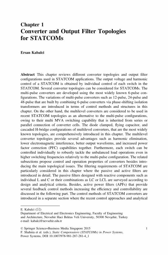
Chapter 1Converter and Output Filter Topologiesfor STATCOMs
Ersan Kabalci
Abstract This chapter reviews different converter topologies and output filterconfigurations used in STATCOM applications. The output voltage and harmoniccontrol of a STATCOM is obtained by individual control of each switch in theSTATCOM. Several converter topologies can be considered for STATCOMs. Themulti-pulse converters are developed using the most widely known 6-pulse con-figurations. The variations of multi-pulse converters such as 12-pulse, 24-pulse and48-pulse that are built by combining 6-pulse converters via phase-shifting isolationtransformers are introduced in terms of control methods and structures in thischapter. On the other hand, the multilevel converters are considered to be used inrecent STATCOM topologies as an alternative to the multi-pulse configurations,owing to their multi MVA switching capability that is inherited from series orparallel connection of converter cells. The diode clamped, flying capacitor, andcascaded H-bridge configurations of multilevel converters, that are the most widelyknown topologies, are comprehensively introduced in this chapter. The multilevelconverter topologies provide several advantages such as harmonic elimination,lower electromagnetic interference, better output waveforms, and increased powerfactor correction (PFC) capabilities together. Furthermore, each switch can becontrolled individually to robustly tackle the unbalanced load operations even inhigher switching frequencies relatively to the multi-pulse configuration. The relatedsubsections propose control and operation properties of converters besides intro-ducing the main topological issues. The filtering requirements of STATCOM areparticularly considered in this chapter where the passive and active filters areintroduced in detail. The passive filters designed with reactive components such asindividual L and C or their combinations as LC or LCL are surveyed according todesign and analytical criteria. Besides, active power filters (APFs) that provideseveral feedback control methods increasing the efficiency and controllability arediscussed in the following part. The control methods of STATCOM converters areintroduced in a separate section where the recent control approaches and analytical
E. Kabalci (&)Department of Electrical and Electronics Engineering, Faculty of Engineeringand Architecture, Nevsehir Haci Bektas Veli University, 50300 Nevşehir, Turkeye-mail: [email protected]
© Springer Science+Business Media Singapore 2015F. Shahnia et al. (eds.), Static Compensators (STATCOMs) in Power Systems,Power Systems, DOI 10.1007/978-981-287-281-4_1
1
calculations required are presented in detail. The block diagrams of the industrialSTATCOM applications are also discussed.
Keywords STATCOM � Converter � Inverter � Filter � Active power filter (APF)
1.1 Introduction
STATCOM is a reactive power (Q) compensation device that is shunt connected tothe AC transmission and distributions systems. The basic topology is based onVoltage Source Converters (VSCs) where the emerging topologies consist of self-commutated switching devices while recent STATCOMs include line commutatedswitches such as thyristors. A STATCOM that is capable of generating or absorbingreactive power to compensate the transmission line is located between generatorsand load [1–3]. This operation principle of STATCOM makes it to act either as asource or a load for the transmission line. STATCOMs are considered as a memberof the Flexible AC Transmission System (FACTS) devices. Furthermore, STAT-COMs can replace Static VAr Compensators (SVC) in distribution systems [1, 2].STATCOM can increase the power quality by performing several compensationssuch as dynamic voltage control, oscillation damping of power line, pursuing thestability during transients, voltage flicker and sag-swell controls, and active andreactive power (PQ) control in transmission and distribution systems. These areachieved since the STATCOM utilizes a VSC with power switches, a closed-loopcontrol system which controls the on-off states of switches, and output filters [3, 4].
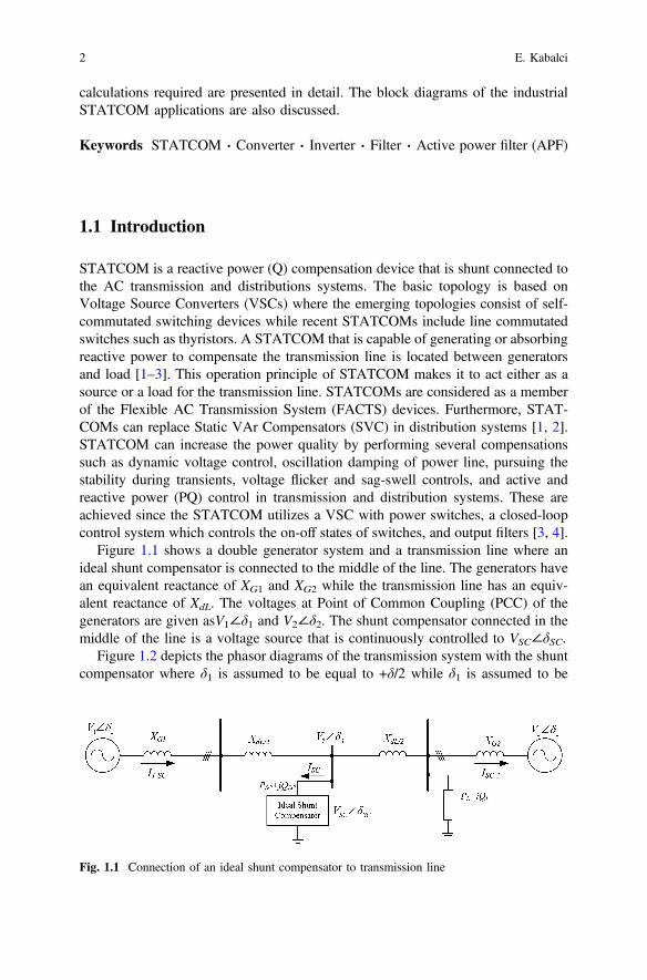
Figure 1.1 shows a double generator system and a transmission line where anideal shunt compensator is connected to the middle of the line. The generators havean equivalent reactance of XG1 and XG2 while the transmission line has an equiv-alent reactance of XdL. The voltages at Point of Common Coupling (PCC) of thegenerators are given asV1∠δ1 and V2∠δ2. The shunt compensator connected in themiddle of the line is a voltage source that is continuously controlled to VSC∠δSC.
Figure 1.2 depicts the phasor diagrams of the transmission system with the shuntcompensator where δ1 is assumed to be equal to +δ/2 while δ1 is assumed to be
Fig. 1.1 Connection of an ideal shunt compensator to transmission line
2 E. Kabalci
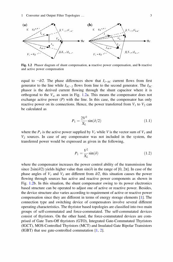
equal to −δ/2. The phase differences show that I1−SC current flows from firstgenerator to the line while ISC−2 flows from line to the second generator. The ISCphasor is the derived current flowing through the shunt capacitor where it isorthogonal to the Vsc as seen in Fig. 1.2a. This means the compensator does notexchange active power (P) with the line. In this case, the compensator has onlyreactive power on its connections. Hence, the power transferred from V1 to V2 canbe calculated as
P1 ¼ 2V2
XLsinðd=2Þ ð1:1Þ
where the P1 is the active power supplied by V1 while V is the vector sum of V1 andV2 sources. In case of any compensator was not included in the system, thetransferred power would be expressed as given in the following,
P1 ¼ V2
XLsinðdÞ ð1:2Þ
where the compensator increases the power control ability of the transmission linesince 2sin(δ/2) yields higher value than sin(δ) in the range of [0, 2π]. In case of thephase angles of V1 and V2 are different from δ/2, this situation causes the powerflowing through sources has active and reactive power components as shown inFig. 1.2b. In this situation, the shunt compensator owing to its power electronicsbased structure can be operated to adjust one of active or reactive power. Besides,the device structure also varies according to requirement of active or reactive powercompensation since they are different in terms of energy storage elements [1]. Theconnection type and switching device of compensators involve several differentoperating characteristics. The thyristor based topologies are classified into two maingroups of self-commutated and force-commutated. The self-commutated devicesconsist of thyristors. On the other hand, the force-commutated devices are com-prised of Gate Turn-Off thyristors (GTO), Integrated Gate-Commutated Thyristors(IGCT), MOS-Controlled Thyristors (MCT) and Insulated Gate Bipolar Transistors(IGBT) that use gate-controlled commutation [1, 2].
Fig. 1.2 Phasor diagram of shunt compensation, a reactive power compensation, and b reactiveand active power compensation
1 Converter and Output Filter Topologies … 3
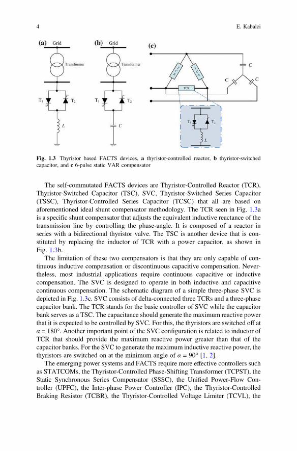
The self-commutated FACTS devices are Thyristor-Controlled Reactor (TCR),Thyristor-Switched Capacitor (TSC), SVC, Thyristor-Switched Series Capacitor(TSSC), Thyristor-Controlled Series Capacitor (TCSC) that all are based onaforementioned ideal shunt compensator methodology. The TCR seen in Fig. 1.3ais a specific shunt compensator that adjusts the equivalent inductive reactance of thetransmission line by controlling the phase-angle. It is composed of a reactor inseries with a bidirectional thyristor valve. The TSC is another device that is con-stituted by replacing the inductor of TCR with a power capacitor, as shown inFig. 1.3b.
The limitation of these two compensators is that they are only capable of con-tinuous inductive compensation or discontinuous capacitive compensation. Never-theless, most industrial applications require continuous capacitive or inductivecompensation. The SVC is designed to operate in both inductive and capacitivecontinuous compensation. The schematic diagram of a simple three-phase SVC isdepicted in Fig. 1.3c. SVC consists of delta-connected three TCRs and a three-phasecapacitor bank. The TCR stands for the basic controller of SVC while the capacitorbank serves as a TSC. The capacitance should generate the maximum reactive powerthat it is expected to be controlled by SVC. For this, the thyristors are switched off atα = 180°. Another important point of the SVC configuration is related to inductor ofTCR that should provide the maximum reactive power greater than that of thecapacitor banks. For the SVC to generate the maximum inductive reactive power, thethyristors are switched on at the minimum angle of α = 90° [1, 2].
The emerging power systems and FACTS require more effective controllers suchas STATCOMs, the Thyristor-Controlled Phase-Shifting Transformer (TCPST), theStatic Synchronous Series Compensator (SSSC), the Unified Power-Flow Con-troller (UPFC), the Inter-phase Power Controller (IPC), the Thyristor-ControlledBraking Resistor (TCBR), the Thyristor-Controlled Voltage Limiter (TCVL), the
Fig. 1.3 Thyristor based FACTS devices, a thyristor-controlled reactor, b thyristor-switchedcapacitor, and c 6-pulse static VAR compensator
4 E. Kabalci
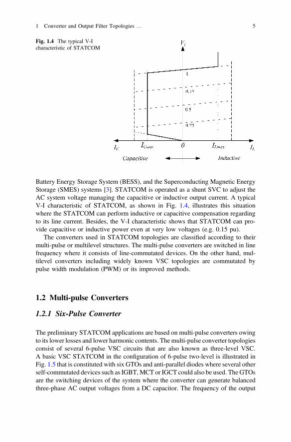
Battery Energy Storage System (BESS), and the Superconducting Magnetic EnergyStorage (SMES) systems [3]. STATCOM is operated as a shunt SVC to adjust theAC system voltage managing the capacitive or inductive output current. A typicalV-I characteristic of STATCOM, as shown in Fig. 1.4, illustrates this situationwhere the STATCOM can perform inductive or capacitive compensation regardingto its line current. Besides, the V-I characteristic shows that STATCOM can pro-vide capacitive or inductive power even at very low voltages (e.g. 0.15 pu).
The converters used in STATCOM topologies are classified according to theirmulti-pulse or multilevel structures. The multi-pulse converters are switched in linefrequency where it consists of line-commutated devices. On the other hand, mul-tilevel converters including widely known VSC topologies are commutated bypulse width modulation (PWM) or its improved methods.
1.2 Multi-pulse Converters
1.2.1 Six-Pulse Converter
The preliminary STATCOM applications are based on multi-pulse converters owingto its lower losses and lower harmonic contents. The multi-pulse converter topologiesconsist of several 6-pulse VSC circuits that are also known as three-level VSC.A basic VSC STATCOM in the configuration of 6-pulse two-level is illustrated inFig. 1.5 that is constituted with six GTOs and anti-parallel diodes where several otherself-commutated devices such as IGBT,MCT or IGCT could also be used. The GTOsare the switching devices of the system where the converter can generate balancedthree-phase AC output voltages from a DC capacitor. The frequency of the output
Fig. 1.4 The typical V-Icharacteristic of STATCOM
1 Converter and Output Filter Topologies … 5
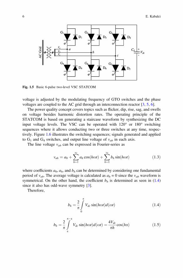
voltage is adjusted by the modulating frequency of GTO switches and the phasevoltages are coupled to the AC grid through an interconnection reactor [3, 5, 6].
The power quality concept covers topics such as flicker, dip, rise, sag, and swellson voltage besides harmonic distortion rates. The operating principle of theSTATCOM is based on generating a staircase waveform by synthesizing the DCinput voltage levels. The VSC can be operated with 120° or 180° switchingsequences where it allows conducting two or three switches at any time, respec-tively. Figure 1.6 illustrates the switching sequences; signals generated and appliedto G1 and G4 switches, and output line voltage of vab in each axis.
The line voltage vab can be expressed in Fourier-series as
vab ¼ a0 þX1h¼1
ah cosðhxtÞ þX1h¼1
bh sinðhxtÞ ð1:3Þ
where coefficients a0, ah, and bh can be determined by considering one fundamentalperiod of vab. The average voltage is calculated as ah = 0 since the vab waveform issymmetrical. On the other hand, the coefficient bh is determined as seen in (1.4)since it also has odd-wave symmetry [3].
Therefore,
bh ¼ 2p
Zp
0
Vdc sinðhxtÞdðxtÞ ð1:4Þ
bh ¼ 2p
Zp�a
a
Vdc sinðhxtÞdðxtÞ ¼ 4Vdc
phcosðhaÞ ð1:5Þ
Fig. 1.5 Basic 6-pulse two-level VSC STATCOM
6 E. Kabalci
) Vab ¼X1
h¼1;3;5
4Vdc
phcosðhaÞ sinðhxtÞ ð1:6Þ
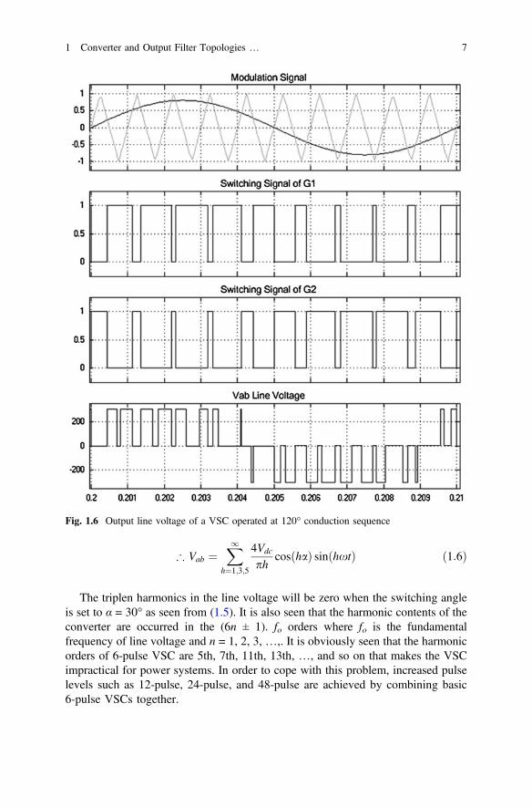
The triplen harmonics in the line voltage will be zero when the switching angleis set to α = 30° as seen from (1.5). It is also seen that the harmonic contents of theconverter are occurred in the (6n ± 1). fo orders where fo is the fundamentalfrequency of line voltage and n = 1, 2, 3, …,. It is obviously seen that the harmonicorders of 6-pulse VSC are 5th, 7th, 11th, 13th, …, and so on that makes the VSCimpractical for power systems. In order to cope with this problem, increased pulselevels such as 12-pulse, 24-pulse, and 48-pulse are achieved by combining basic6-pulse VSCs together.
Fig. 1.6 Output line voltage of a VSC operated at 120° conduction sequence
1 Converter and Output Filter Topologies … 7
1.2.2 12-Pulse Converter
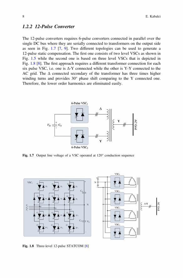
The 12-pulse converters requires 6-pulse converters connected in parallel over thesingle DC bus where they are serially connected to transformers on the output sideas seen in Fig. 1.7 [7, 9]. Two different topologies can be used to generate a12-pulse static compensation. The first one consists of two level VSCs as shown inFig. 1.5 while the second one is based on three level VSCs that is depicted inFig. 1.8 [8]. The first approach requires a different transformer connection for eachsix pulse VSC, i.e. one is Δ-Y connected while the other is Y-Y connected to theAC grid. The Δ connected secondary of the transformer has three times higherwinding turns and provides 30° phase shift comparing to the Y connected one.Therefore, the lower order harmonics are eliminated easily.
Fig. 1.7 Output line voltage of a VSC operated at 120° conduction sequence
Fig. 1.8 Three-level 12-pulse STATCOM [8]
8 E. Kabalci
The phase-a output voltage of STATCOM in any instant can be calculated byusing (1.7) where n1 and n2 are the voltage ratios of the corresponding VSCtransformers while va−Y and va−Δ are the output voltages of the Y-Y and Δ-Yconnected converters, respectively [7].
va ¼ n1va;Y þ n2va;Dffiffiffi3
p ð1:7Þ
The amplitude of VSC output voltage depends on the modulation index (mi) ofthe controlling signal that allows obtaining the output voltage at miVdc where Vdc isthe voltage across the capacitor. The control signal that is based on some variationof PWM generates the switching angle α which subsequently generates theSTATCOM bus voltage. The Eq. (1.8) expresses the admittance of the transformer
Y ¼ 1Rþ jX
¼ Gþ jB ð1:8Þ
that manages the active or reactive power injection to the utility grid. The reactivepower generation or absorption capability of STATCOM depends to the voltagethat is generated by modulation of controller. The injected reactive power by theSTATCOM can be presented as
Q ¼ V2B� miVdcVB cosðd� aÞ þ miVdcVG sinðd� aÞ ð1:9Þ
In case of V > miVdc, Q will be positive that causes STATCOM to absorbreactive power and vice versa [7]. The active power generated by utility grid tocharge the capacitor is expressed by
P ¼ Vj jmiVdc
Xsinðd� aÞ ð1:10Þ
The three-level 12-pulse STATCOM requires 2α phase angle to vary theamplitude of VSC output voltage that controls the reactive power of utility grid.The phase angle δ between the AC bus voltage Vac and STATCOM output voltageV sustains the DC line voltage Vdc at a constant value. The active and reactivepowers are calculate as
P ¼ VacV sin dX
ð1:11Þ
Q ¼ VacVac � V sin d
X
� �ð1:12Þ
where X is considered as the reactance along with STATCOM and utility grid[8–12].
The fundamental VSC voltage V regarding to operation modes is given as
1 Converter and Output Filter Topologies … 9
V ¼ 2V1 cos a ð1:13Þ
where V1 is the fundamental voltage of each VSC block seen in Fig. 1.8. The reactivepower flows from utility grid to STATCOM while the capacitive operation modesupplies reactive power to utility grid from STATCOM. The operation of STAT-COM given in Fig. 1.8 is carried out by applying 30° phase shift between VSC1 andVSC3 owing to their Y and Δ connection respectively on the primary windings oftransformer. On the other hand, same connection and phase shift angles are suppliedfor VSC2 and VSC4 that are other sets of three-level 12-pulse VSC [8, 11, 12].
1.2.3 24-Pulse Converter
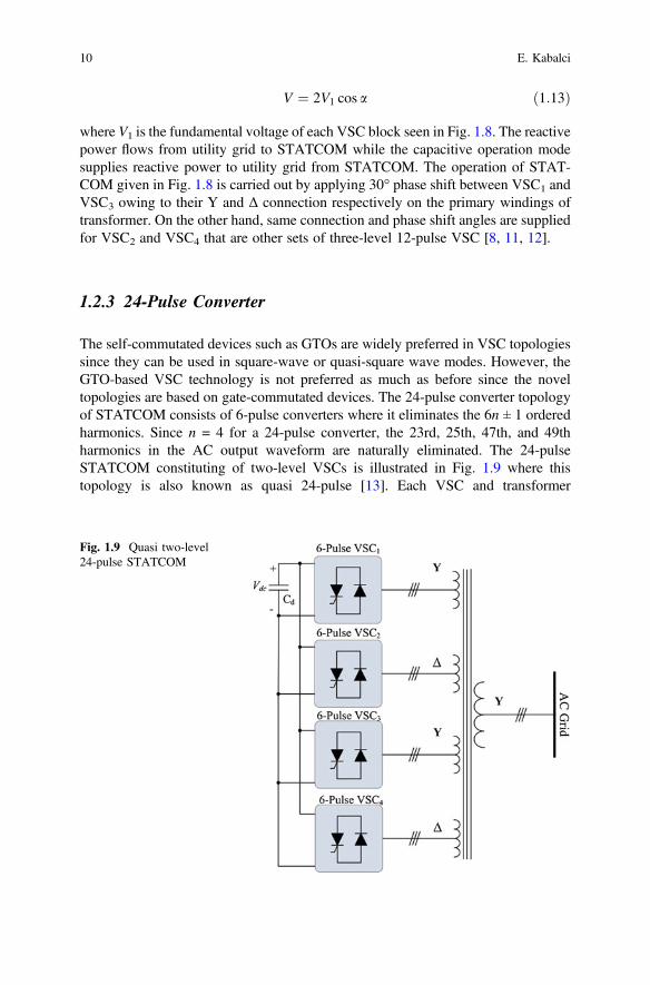
The self-commutated devices such as GTOs are widely preferred in VSC topologiessince they can be used in square-wave or quasi-square wave modes. However, theGTO-based VSC technology is not preferred as much as before since the noveltopologies are based on gate-commutated devices. The 24-pulse converter topologyof STATCOM consists of 6-pulse converters where it eliminates the 6n ± 1 orderedharmonics. Since n = 4 for a 24-pulse converter, the 23rd, 25th, 47th, and 49thharmonics in the AC output waveform are naturally eliminated. The 24-pulseSTATCOM constituting of two-level VSCs is illustrated in Fig. 1.9 where thistopology is also known as quasi 24-pulse [13]. Each VSC and transformer
Fig. 1.9 Quasi two-level24-pulse STATCOM
10 E. Kabalci
connection builds a stage that each stage is connected to the utility grid over Y-Yand Δ-Y connections of transformers. The transformers are connected in zigzag thatgenerates 15° phase shift according to each other with −7.5°, 7.5°, 22.5°, and 37.5°angles [13, 14].
Another topology of quasi 24-pulse STATCOM is presented in [15] where theVSCs are constituted according to neutral point clamping (NPC) topology that ispreviously shown in Fig. 1.8. The conduction angle α defines the negative andpositive cycles of intervals where α = 180 − 2β, that 2β stands for the dead-bandangle. The on–off spectral transitions are ensured by the dead-band angle where theoutput voltages of a 6-pulse three-level VSC is given by
V1 ¼ 2ffiffiffi6
p
pvdc2sin
180� 2b2
� �ð1:14Þ
On the other hand, output voltages of a 24-pulse three-level VSC is given as in(1.15) while the active and reactive powers are calculated by using (1.11) and (1.12)[15–17],
Vc1 ¼ np2
ffiffiffi6
p
6pvdc2sin
180� 2b2
� �cos
p24
ð1:15Þ
1.2.4 48-Pulse Converter
The most important benefit of the multi-pulse converters is the harmonic elimi-nating owing to the 6n ± 1 ratio. The 48-pulse converter based STATCOM is themost important VSC type to reduce lower ordered harmonics since harmonic ordersappears at 47th, 49th, 95th, and 97th orders that are managed by 48n ± 1 ratio ofeight 6-pulse VSCs. Furthermore, this facility of 48-puse converter allows using inhigh power FACTS without requiring any ac filter. The topology includes 6-pulseVSCs as introduced in previous devices where the phase shifts and transformerconnections are depicted similarly in Fig. 1.10 [17].
The transformer connections are realized with zigzag type on primary side andY/Δ types on secondary sides where the outputs of phase shifting sides are con-nected in series in order to eliminate lower order harmonics [18, 19]. The operationof 48-pulse STATCOM is depended on appropriate phase shift angles applied toVSCs and arranged between transformer connections. The proper shifting anglesare shown in Table 1.1 where switching signals of each VSC are generated byconsidering these orders. The transformer connection types and phase shift anglesare also done according to this order and therefore high quality sinusoidal outputvoltage is generated to compensate the utility grid [17, 19].
1 Converter and Output Filter Topologies … 11
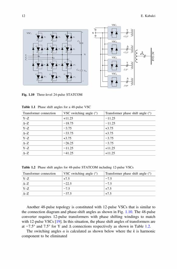
Another 48-pulse topology is constituted with 12-pulse VSCs that is similar tothe connection diagram and phase-shift angles as shown in Fig. 1.10. The 48-pulseconverter requires 12-pulse transformers with phase shifting windings to matchwith 12-pulse VSCs [19]. In this situation, the phase shift angles of transformers areat −7.5° and 7.5° for Y and Δ connections respectively as shown in Table 1.2.
The switching angles α is calculated as shown below where the k is harmoniccomponent to be eliminated
Fig. 1.10 Three-level 24-pulse STATCOM
Table 1.1 Phase shift angles for a 48-pulse VSC
Transformer connection VSC switching angle (°) Transformer phase shift angle (°)
Y–Z +11.25 −11.25
Δ–Z −18.75 −11.25
Y–Z −3.75 +3.75
Δ–Z −33.75 +3.75
Y–Z +3.75 −3.75
Δ–Z −26.25 −3.75
Y–Z −11.25 +11.25
Δ–Z −41.25 +11.25
Table 1.2 Phase shift angles for 48-pulse STATCOM including 12-pulse VSCs
Transformer connection VSC switching angle (°) Transformer phase shift angle (°)
Y–Z +7.5 −7.5
Δ–Z −22.5 −7.5
Y–Z −7.5 +7.5
Δ–Z −37.5 +7.5
12 E. Kabalci