Embed Size (px)
Citation preview

c I
1
FASSI CRANE
F 360SE.24 use and maintenance
INDEX
Chapter I INTRODUCTION page 2
II SAFETY NORMS page 3
III INSTRUCTIONS FOR CRANE USE page 7
IV IDENTIFICATION OF THE CRANE MODEL page 8
V TECHNICAL DATA page 9
VI CRANE NOMENCLATURE page 12
VII SAFETY AND PROTECTION DEVICES page 14
VIII LIFTING MOMENT LIMITING DEVICE page 16
IX CONTROLS TO STABILIZE THE VEHICLE page 18
X CONTROLS TO OPERATE THE CRANE page 20
XI USE OF IMPLEMENTS page 23
XII MAINTENANCE INSTRUCTIONS page 24
XIII POSSIBLE FAULTS page 28
XIV HYDRAULIC AND ELECTRIC SCHEMATICS page 29
XV OIL AND LUBRICANT CHARACTERISTICS page 35
A INSTRUCTION AND WARNING PLATES page 36
B CAPACITY PLATES page 40
Edition 25.08.2004

FASSI CRANE
F 360SE.24 use and maintenance
This instruction manual describes the FASSI CRANE F360SE.24.
The fitment must be carried out in accordance with the instructions givenby the Manufacturer in the manual for hydraulic crane fitting.
The Manufacturer declines all responsibility and guarantee if the fitting isentrusted to workshops without sufficient technical capability to carry outthe work in conformity.
As well as the principal safety norms, this manual contains a description ofthe crane and the instructions for use and maintenance.
The crane must only be operated by responsible persons, previouslyinstructed and authorized.
THANK YOU FOR SELECTING ONE OF OUR CRANES.
c IINTRODUCTIONF 360SE.24
2

SAFETY NORMS
( ! ) This symbol draws your attention on the points concerning safety.It means: WARNING! BE CAREFUL!
IT CONCERNS YOUR SAFETY!
!ATTENTION!
READ THIS MANUAL CAREFULLY prior to use of the crane or any maintenance.A few minutes spent now could save time and labour later. Be sure that theunit has been installed, inspected and tested in accordance with the locallegal requirements.
To operate the crane it is necessary to fully understand its working, safetyand warranty norms.
Check that protections are in their place and that all safety devices are fittedand active.
Warning plates, as well as instruction and operation plates must be replacedwhen no longer readable or missing. (See chapters A - B)
Do not run the engine in a indoor area without first making sure there isadequate ventilation. Fit a suitable extension tube to the vehicle exhaust pipeto take the fumes away from the working area.
Stabilize the vehicle checking that they rest on a solid base; if necessary uselarger outrigger base plates (available on request) to avoid sinking. If you adoptother means, make sure that they are suitably sized for the load they must bear.
Stabilize the vehicle on a horizontal plane with a maximum tolerance of 1,5degrees.
Never operate the outriggers when the crane is loaded.
Remember that the stability of the unit (crane-vehicle) is only guaranteed bythe fully lateral extension of the outriggers.
Should visibility be insufficient, make sure that control stations are properlylighted so as to ensure safety while operating control functions and allow rea-ding of the plates.
Before manoeuvering a load check that theworking area is adequate and properly lighted foryour crane.
Make sure that the hook is always free to rotateon its pin and that nothing obstructs its verticalpositioning.
Check the efficiency of the hook safety catch.
c IISAFETY NORMS
F 360SE
3
c IISAFETY NORMSF 360SE
4
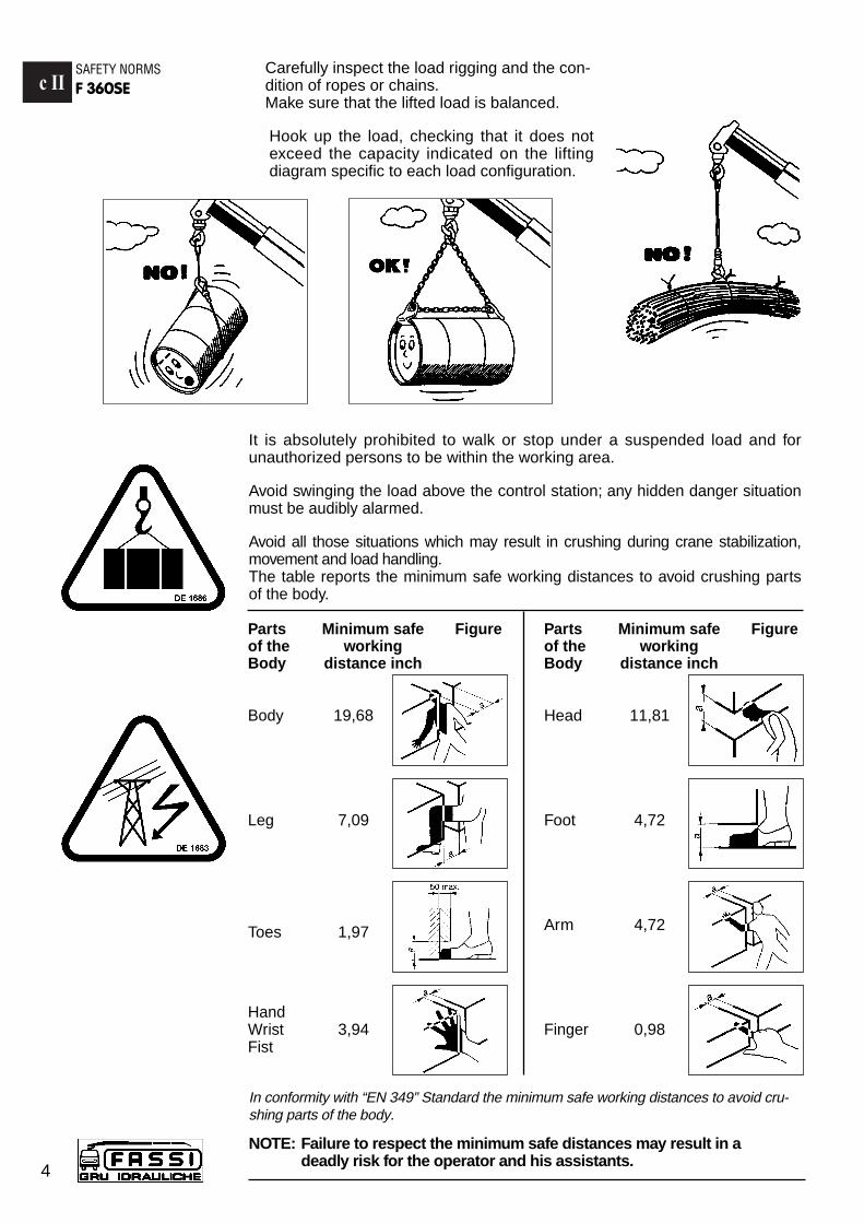
Carefully inspect the load rigging and the con-dition of ropes or chains.Make sure that the lifted load is balanced.
Hook up the load, checking that it does notexceed the capacity indicated on the liftingdiagram specific to each load configuration.
It is absolutely prohibited to walk or stop under a suspended load and forunauthorized persons to be within the working area.
Avoid swinging the load above the control station; any hidden danger situationmust be audibly alarmed.
Avoid all those situations which may result in crushing during crane stabilization,movement and load handling.The table reports the minimum safe working distances to avoid crushing partsof the body.
In conformity with “EN 349” Standard the minimum safe working distances to avoid cru-shing parts of the body.
NOTE: Failure to respect the minimum safe distances may result in adeadly risk for the operator and his assistants.
Parts Minimum safe Figureof the workingBody distance inch
Body 19,68
Leg 7,09
Toes 1,97
HandWrist 3,94Fist
Parts Minimum safe Figureof the workingBody distance inch
Head 11,81
Foot 4,72
Arm 4,72
Finger 0,98
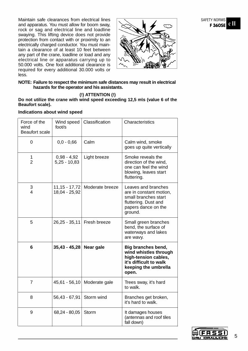
Maintain safe clearances from electrical linesand apparatus. You must allow for boom sway,rock or sag and electrical line and loadlineswaying. This lifting device does not provideprotection from contact with or proximity to anelectrically charged conductor. You must main-tain a clearance of at least 10 feet betweenany part of the crane, loadline or load and anyelectrical line or apparatus carrying up to50.000 volts. One foot additional clearance isrequired for every additional 30.000 volts orless.
NOTE: Failure to respect the minimum safe distances may result in electricalhazards for the operator and his assistants.
(!) ATTENTION (!)Do not utilize the crane with wind speed exceeding 12,5 m\s (value 6 of theBeaufort scale).
Indications about wind speed
Force of the Wind speed Classification Characteristicswind foot/sBeaufort scale
0 0,0 - 0,66 Calm Calm wind, smoke goes up quite vertically
1 0,98 - 4,92 Light breeze Smoke reveals the 2 5,25 - 10,83 direction of the wind,
one can feel the windblowing, leaves startfluttering.
3 11,15 - 17,72 Moderate breeze Leaves and branches4 18,04 - 25,92 are in constant motion,
small branches startfluttering. Dust andpapers dance on theground.
5 26,25 - 35,11 Fresh breeze Small green branchesbend, the surface ofwaterways and lakes are wavy.
6 35,43 - 45,28 Near gale Big branches bend,wind whistles through high-tension cables,it's difficult to walk keeping the umbrellaopen.
7 45,61 - 56,10 Moderate gale Trees sway, it's hard to walk.
8 56,43 - 67,91 Storm wind Branches get broken,it's hard to walk.
9 68,24 - 80,05 Storm It damages houses(antennas and roof tiles fall down)
c IISAFETY NORMS
F 360SE
5
For cranes with top seat controls, it is necessary to use a ladder and a catwalk to reach the control station.When operating from the top seat, stay within its side safety guards.
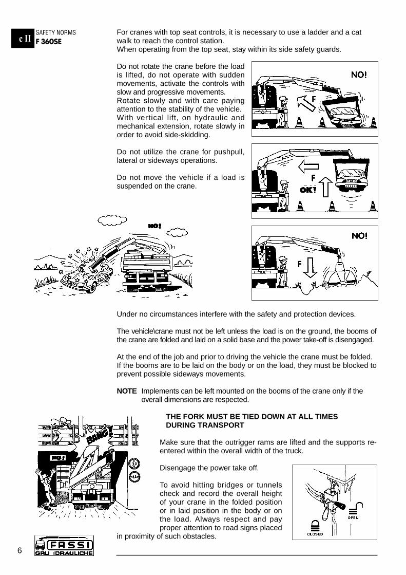
Do not rotate the crane before the loadis lifted, do not operate with suddenmovements, activate the controls withslow and progressive movements.Rotate slowly and with care payingattention to the stability of the vehicle. With vertical lift, on hydraulic andmechanical extension, rotate slowly inorder to avoid side-skidding.
Do not utilize the crane for pushpull,lateral or sideways operations.
Do not move the vehicle if a load issuspended on the crane.
Under no circumstances interfere with the safety and protection devices.
The vehicle\crane must not be left unless the load is on the ground, the booms ofthe crane are folded and laid on a solid base and the power take-off is disengaged.
At the end of the job and prior to driving the vehicle the crane must be folded. If the booms are to be laid on the body or on the load, they must be blocked toprevent possible sideways movements.
NOTE Implements can be left mounted on the booms of the crane only if the overall dimensions are respected.
THE FORK MUST BE TIED DOWN AT ALL TIMES DURING TRANSPORT
Make sure that the outrigger rams are lifted and the supports re-entered within the overall width of the truck.
Disengage the power take off.
To avoid hitting bridges or tunnelscheck and record the overall heightof your crane in the folded positionor in laid position in the body or onthe load. Always respect and payproper attention to road signs placed
in proximity of such obstacles.
c IISAFETY NORMSF 360SE
6
c IIIINSTRUCTIONS
FOR CRANE USEF 360SE
7
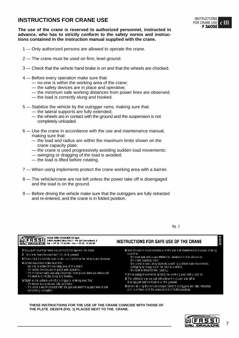
INSTRUCTIONS FOR CRANE USE
The use of the crane is reserved to authorized personnel, instructed inadvance, who has to strictly conform to the safety norms and instruc-tions contained in the instruction manual supplied with the crane.
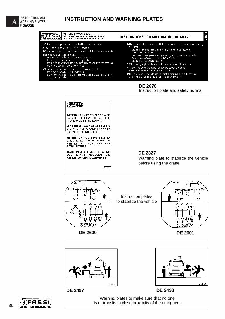
1 — Only authorized persons are allowed to operate the crane.
2 — The crane must be used on firm, level ground.
3 — Check that the vehicle hand brake is on and that the wheels are chocked.
4 — Before every operation make sure that:— no-one is within the working area of the crane;— the safety devices are in place and operative;— the minimum safe working distances from power lines are observed;— the load is correctly slung and hooked.
5 — Stabilize the vehicle by the outrigger rams, making sure that:— the lateral supports are fully extended;— the wheels are in contact with the ground and the suspension is not
completely unloaded.
6 — Use the crane in accordance with the use and maintenance manual,making sure that:— the load and radius are within the maximum limits shown on the
crane capacity plate;— the crane is used progressively avoiding sudden load movements;— swinging or dragging of the load is avoided;— the load is lifted before rotating.
7 — When using implements protect the crane working area with a barrier.
8 — The vehicle/crane are not left unless the power take off is disengagedand the load is on the ground.
9 — Before driving the vehicle make sure that the outriggers are fully retractedand re-entered, and the crane is in folded position.
THESE INSTRUCTIONS FOR THE USE OF THE CRANE COINCIDE WITH THOSE OFTHE PLATE DE2676 (FIG. 1) PLACED NEXT TO THE CRANE.
fig. 1
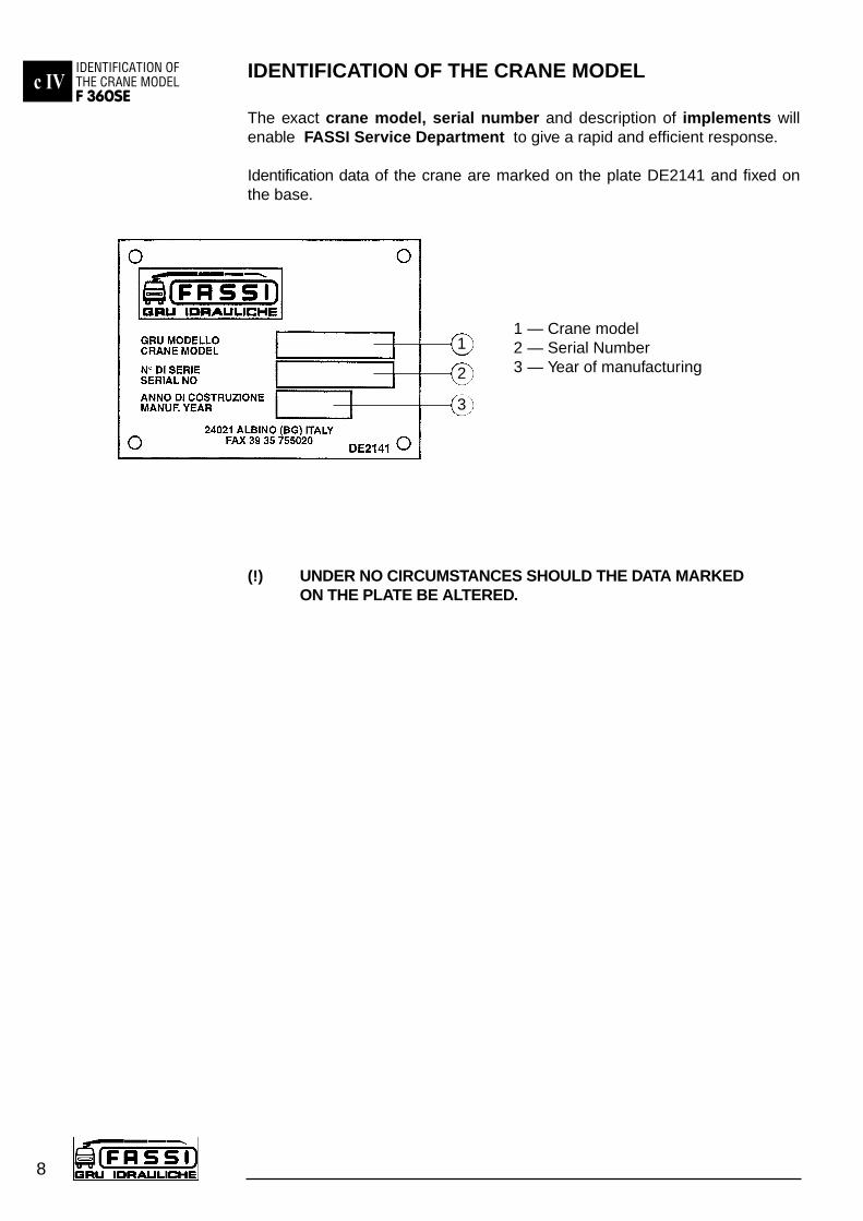
IDENTIFICATION OF THE CRANE MODEL
The exact crane model, serial number and description of implements willenable FASSI Service Department to give a rapid and efficient response.
Identification data of the crane are marked on the plate DE2141 and fixed onthe base.
1 — Crane model2 — Serial Number3 — Year of manufacturing
(!) UNDER NO CIRCUMSTANCES SHOULD THE DATA MARKEDON THE PLATE BE ALTERED.
1
2
3
c IVIDENTIFICATION OFTHE CRANE MODELF 360SE
8
c VTECHNICAL DATA
F 360SE
9
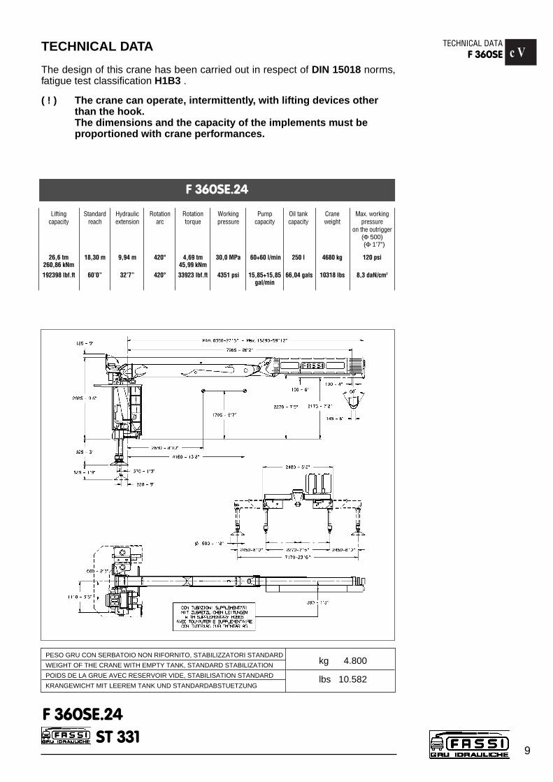
TECHNICAL DATA
The design of this crane has been carried out in respect of DIN 15018 norms,fatigue test classification H1B3 .
( ! ) The crane can operate, intermittently, with lifting devices other than the hook.The dimensions and the capacity of the implements must be proportioned with crane performances.
ST 331F 360SE.24
PESO GRU CON SERBATOIO NON RIFORNITO, STABILIZZATORI STANDARD
WEIGHT OF THE CRANE WITH EMPTY TANK, STANDARD STABILIZATION
POIDS DE LA GRUE AVEC RESERVOIR VIDE, STABILISATION STANDARD
KRANGEWICHT MIT LEEREM TANK UND STANDARDABSTUETZUNG
kg 4.800
lbs 10.582
F 360SE.24
Lifting Standard Hydraulic Rotation Rotation Working Pump Oil tank Crane Max. workingcapacity reach extension arc torque pressure capacity capacity weight pressure
on the outrigger(Φ 500)(Φ 1’7”)
26,6 tm 18,30 m 9,94 m 420° 4,69 tm 30,0 MPa 60+60 l/min 250 l 4680 kg 120 psi260,86 kNm 45,99 kNm
192398 lbf.ft 60’0” 32’7” 420° 33923 lbf.ft 4351 psi 15,85+15,85 66,04 gals 10318 lbs 8,3 daN/cm2
gal/min
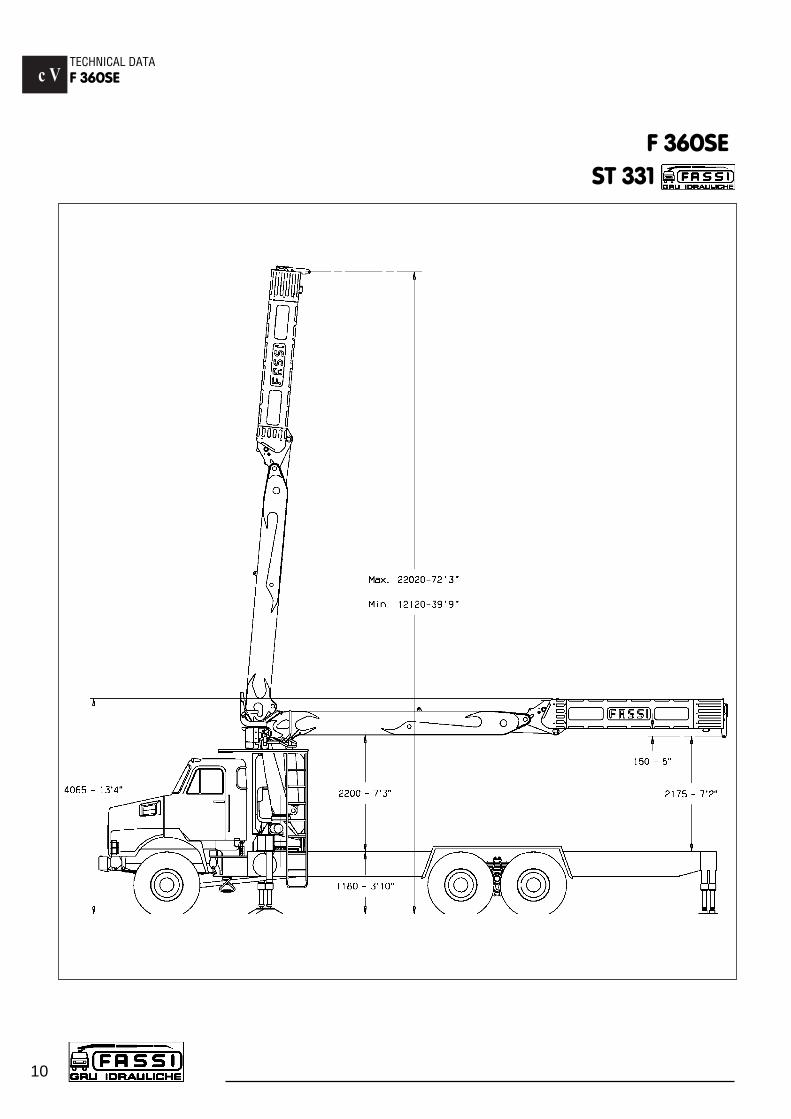
c VTECHNICAL DATAF 360SE
10
F 360SEST 331
c VTECHNICAL DATA
F 360SE
11
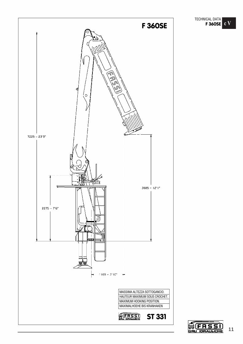
ST 331
F 360SE
MASSIMA ALTEZZA SOTTOGANCIO.HAUTEUR MAXIMUM SOUS CROCHET.MAXIMUM HOOKING POSITION.MAXIMALHOEHE BIS KRANHAKEN

c VICRANE NOMENCLATUREF 360SE
12
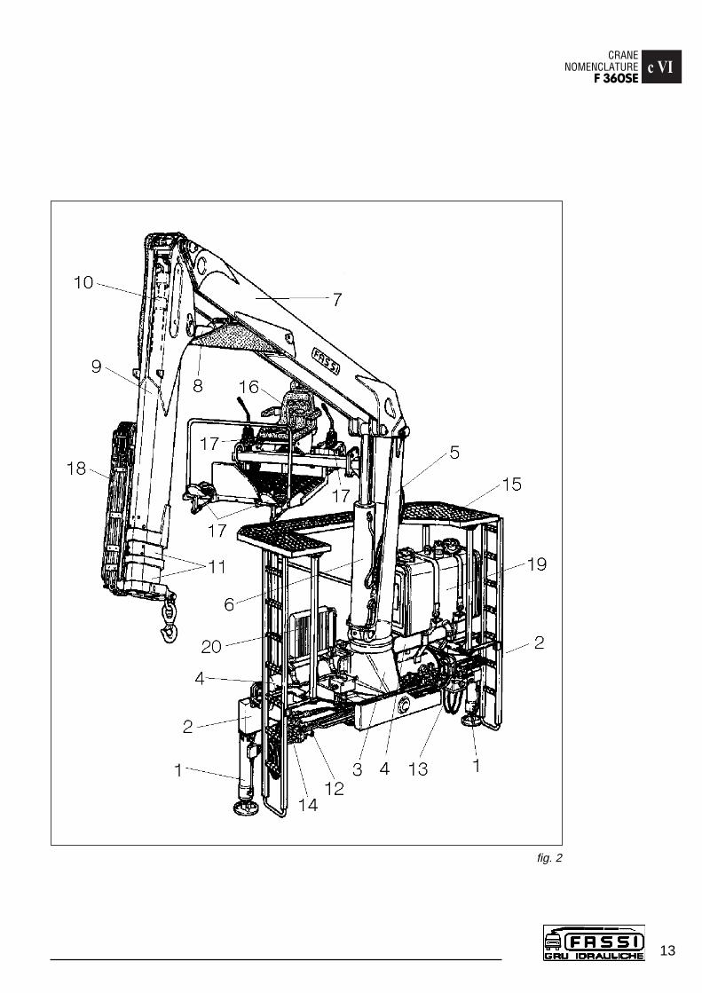
CRANE NOMENCLATURE (fig. 2)
Pos. Description1 - Outrigger rams2 - Outrigger supports3 - Base4 - Rotation cylinders5 - Column6 - Inner ram7 - Inner boom8 - Outer ram9 - Outer boom
10 - Booms extension rams11 - Extension boom sections12 - Deviator crane - outriggers13 - Outrigger distributors14 - Outrigger transmission15 - Ladder and cat walk16 - Seat and control station17 - Manual and foot controls (crane distributors)18 - Supplementary hoses (hydraulic implements)19 - Oil tank20 - Heat exchanger (available on request)
c VICRANE
NOMENCLATUREF 360SE
13
fig. 2

c VIISAFETY AND PROTECTION DEVICESF 360SE
14
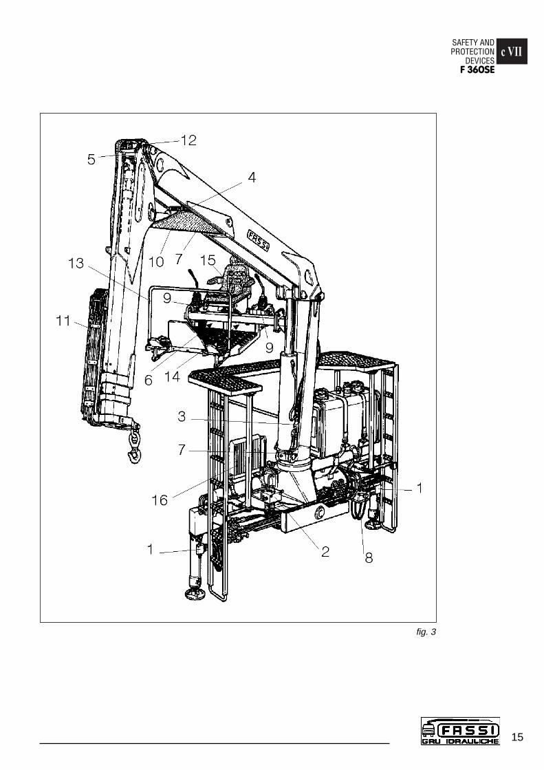
SAFETY AND PROTECTION DEVICES (fig. 3)
Pos. Description1 - Check valves for outrigger rams2 - Check valve for rotation control3 - Check valve for inner ram4 - Check valve for outer ram5 - Check valve for booms extension rams6 - Lifting moment limiting device assembly7 - Parachute valves (lifting moment limiting device)8 - Main pressure valves (outrigger distributor)9 - Main pressure and auxiliary valves (crane distributors)
10 - Carter for outer ram11 - Carter for hose protection devices12 - Carter for booms extensions ram check valve13 - Handle14 - Emrgency tap (lifting moment limiting device)15 - Seat with device indicating the operator presence16 - Heat exchanger (available on request)
(!) Before crane use check that safety and protection devices are fitted and active.
(!) Under no circumstances interfere with the safety and protection devices.
(!) Interference with the check valves and removal of the lead seals removethe Manufacturer and invalidate the warranty.
(!) For the access to the top seat use a ladder and a cat walk.
c VIISAFETY AND PROTECTION
DEVICESF 360SE
15
fig. 3
c VIIILIFTING MOMENTLIMITING DEVICEF 360SE
16
LIFTING MOMENT LIMITING DEVICE
A characteristic which permits the classification of cranes is their lifting capa-city or maximum lifting moment. The moment is defined by the value obtainedfrom the product of the load to be lifted (in lbs) by its distance (in ft) from thecenterline of the crane rotation.
The device called “lifting moment limiting device” preserves the crane structu-re from overloads, as it prevents any movement which increases the value ofthe moment up to the maximum established value.
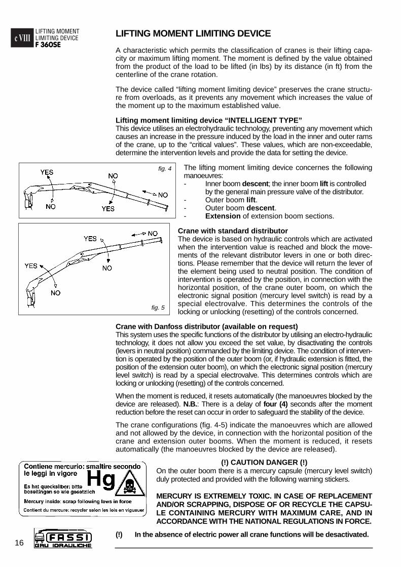
Lifting moment limiting device “INTELLIGENT TYPE”This device utilises an electrohydraulic technology, preventing any movement whichcauses an increase in the pressure induced by the load in the inner and outer ramsof the crane, up to the “critical values”. These values, which are non-exceedable,determine the intervention levels and provide the data for setting the device.
The lifting moment limiting device concernes the followingmanoeuvres:- Inner boom descent; the inner boom lift is controlled
by the general main pressure valve of the distributor.- Outer boom lift.- Outer boom descent.- Extension of extension boom sections.
Crane with standard distributorThe device is based on hydraulic controls which are activatedwhen the intervention value is reached and block the move-ments of the relevant distributor levers in one or both direc-tions. Please remember that the device will return the lever ofthe element being used to neutral position. The condition ofintervention is operated by the position, in connection with thehorizontal position, of the crane outer boom, on which theelectronic signal position (mercury level switch) is read by aspecial electrovalve. This determines the controls of thelocking or unlocking (resetting) of the controls concerned.
Crane with Danfoss distributor (available on request)This system uses the specific functions of the distributor by utilising an electro-hydraulictechnology, it does not allow you exceed the set value, by disactivating the controls(levers in neutral position) commanded by the limiting device. The condition of interven-tion is operated by the position of the outer boom (or, if hydraulic extension is fitted, theposition of the extension outer boom), on which the electronic signal position (mercurylevel switch) is read by a special electrovalve. This determines controls which arelocking or unlocking (resetting) of the controls concerned.
When the moment is reduced, it resets automatically (the manoeuvres blocked by thedevice are released). N.B.: There is a delay of four (4) seconds after the momentreduction before the reset can occur in order to safeguard the stability of the device.
The crane configurations (fig. 4-5) indicate the manoeuvres which are allowedand not allowed by the device, in connection with the horizontal position of thecrane and extension outer booms. When the moment is reduced, it resetsautomatically (the manoeuvres blocked by the device are released).
(!) CAUTION DANGER (!)On the outer boom there is a mercury capsule (mercury level switch)duly protected and provided with the following warning stickers.
MERCURY IS EXTREMELY TOXIC. IN CASE OF REPLACEMENTAND/OR SCRAPPING, DISPOSE OF OR RECYCLE THE CAPSU-LE CONTAINING MERCURY WITH MAXIMUM CARE, AND INACCORDANCE WITH THE NATIONAL REGULATIONS IN FORCE.
(!) In the absence of electric power all crane functions will be desactivated.
fig. 5
fig. 4
c VIIILIFTING MOMENTLIMITING DEVICE
F 360SE
17
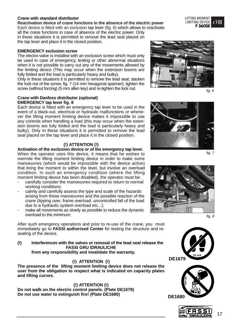
Crane with standard distributorReactivation device of crane functions in the absence of the electric powerEach device is fitted with an exclusion tap lever (fig. 6) which allows to reactivateall the crane functions in case of absence of the electric power. Onlyin these situations it is permitted to remove the lead seal placed onthe tap lever and place it in the closed position.
EMERGENCY exclusion screwThe electro-valve is installed with an exclusion screw which must onlybe used in case of emergency, testing or other abnormal situationswhen it is not possible to carry out any of the movements allowed bythe limiting device (This may occur when the extension booms arefully folded and the load is particularly heavy and bulky). Only in these situations it is permitted to remove the lead seal; slackenthe lock nut of the screw, fig. 7 (14 mm hexagonal spanner), tighten thescrew (without forcing) (5 mm allen key) and re-tighten the lock nut.
Crane with Danfoss distributor (optional) EMERGENCY tap lever fig. 8Each device is fitted with an emergency tap lever to be used in theevent of a black-out, electrical or hydraulic malfunctions or whene-ver the lifting moment limiting device makes it impossible to useany controls when handling a load (this may occur when the exten-sion booms are fully folded and the load is particularly heavy andbulky). Only In these situations it is permitted to remove the leadseal placed on the tap lever and place it in the closed position.
(!) ATTENTION (!)Activation of the exclusion device or of the emergency tap lever.When the operator uses this device, it means that he wishes tooverride the lifting moment limiting device in order to make somemanoeuvres (which would be impossible with the device active)that bring the moment to within the level, but involve an overloadcondition. In such an emergency condition (where the liftingmoment limiting device has been disabled), the operator must be:- carefully consider the manoeuvres required to return to normal
working conditions;- calmly and carefully assess the type and scale of the hazards
arising from these manoeuvres and the possible reaction of thecrane (tipping over, frame overload, uncontrolled fall of the load due to a hydraulic system overload etc...);
- make all movements as slowly as possible to reduce the dynamic overload to the minimum.
After such emergency operations and prior to re-use of the crane, you mustimmediately go to FASSI authorised Center for testing the structure and re-sealing of the device.
(!) Interferences with the valves or removal of the lead seal release theFASSI GRU IDRAULICHE
from any responsibility and invalidate the warranty.
(!) ATTENTION (!)The presence of the lifting moment limiting device does not release theuser from the obligation to respect what is indicated on capacity platesand lifting curves.
(!) ATTENTION (!)Do not walk on the electric control panels. (Plate DE1679)Do not use water to estinguish fire! (Plate DE1680)
fig. 8
fig. 6
fig. 7
DE1679
DE1680

c IXCONTROLS TO STABILIZETHE VEHICLEF 360SE
18
CONTROLS TO STABILIZE THE VEHICLE
The outriggers rams prevent harmful stresses both to the frame and to thevehicle suspensions on which the crane is mounted and assure the stability ofthe unit during load handling.
Be very careful during vehicle stabilization operation; make sure that no one isor transits in close proximity of the working area of the outriggers.
(!) ATTENTION (!)The crane stability is only guaranteed by the maximum lateral extension of theoutrigger supports and by the solidity of the base underneath the plates of theoutrigger rams. To check the maximum working pressure see Paragraph D0.1Technical data
When stabilization is complete the wheels of the vehicle must still be in contact withthe ground and the suspensions must not be fully unloaded.
Stabilize the crane so as to operate on a horizontal plane with a maximum toleranceof 1,5 degrees.
Description of the controls to stabilize the vehicle
The controls to stabilize the vehicle are activated only on ground level and onboth sides of the crane base.
The extension and re-entering of the support and outrigger rams indicated on thefig. 9-10 coincide with what indicated on the plates DE2600 and DE2601 placednext to the control stations.
The symbols and the graphics of the plates define the vehicle side from whichyou operate and indicate the operating levers in relation to their movement.
On the plate DE2600 is also reported the oil diverter (placed on the side of thebase beam, on the left side of the vehicle) with the position of the lever for - E/Scontrol (E=extensions, S=outriggers).
Lever function fig. 9-10
- E1 Control for outrigger support extension E1 crane - E2 Control for outrigger support extension E2 crane- S1 Outrigger ram control S1 crane- S2 Outrigger ram control S2 crane
Controls for positioning the outriggers of the crane
(!) ATTENTION (!)When controlling from the opposite side of the vehicle (it is not possiblevisually check the operation) it is compulsory make sure that no one is ortransits in close proximity of the outriggers. (Fig. 11 plate DE2497 and fig.12 plate DE2498).
fig. 9
fig. 11 fig. 12
fig. 10

- Position lever D of oil diverter - E/S, (placed on the beam of the crane base, on the left side of the vehicle), on E/S (extensions - outriggers).
Extension of the outrigger support E1- Operate the lever E1 to extend the support.Extension of the outrigger support E2- Operate the lever E2 to extend the support.Descent of the outrigger ram S1- Operate the lever S1 to lower the ram. Descent of the outrigger ram S2- Operate the lever S2 to lower the ram.
(!) ATTENTION (!)The complete extension of the outrigger supports is visually indicated bythe yellow triangles which are found at the end of the beam. (Fig. 13)The stabilization has to be carried out with care and gradually keeping thevehicle in horizontal levelled condition to prevent springs overloads andchassis torsions.
(!) ATTENTION (!) During the stabilisation operations, for each outrigger ram, it is recom-mended to DESCENT the outrigger as last manoeuvre.
Unfold the crane into a working condition, positioning lever D of oil divertercrane-outriggers ( - E/S) on . fig. 9.
Manoeuvres for re-entry of the crane outriggers after crane use.
- Position lever D of oil-diverter ( - E/S) on E/S (extensions-outriggers). fig. 9.
Re-entry of the outrigger ram S1- Operate the lever S1 to control the re-entry (at stroke end) of the ram.Re-entry of the outrigger ram S2- Operate the lever S2 to control the re-entry of the ram.Re-entry of the outrigger support E1- Operate the lever E1 to control the re-entry of the support.Re-entry of the outrigger support E2- Operate the lever E2 to control the re-entry of the support.
(!) WARNING (!)Due to the particular characteristic of the hydraulic circuit (double circuitwith two pumps), the distributor placed on the right of the top seat (outerboom, pallet-fork and extension booms) is alimented by one pump alsowith the oil-diverter - E/S on E/S; the distributor controls are disactivatedby a device indicating the operator presence which prevents the controlactivation before the operator sits down at the control station.
(!) Under no circumstances interfere with the device indicating the operator presence which is fitted on the seat of the control station.
c IXCONTROLS
TO STABILIZETHE VEHICLE
F 360SE
19
fig. 13

CONTROLS TO OPERATE THE CRANE
(!) WARNING (!)Before operating the crane it is compulsory to set the outriggers
This coincides with that indicated on the plate DE2327 placed on the outriggers.(Fig. 14)
(!) Operate the levers smoothly and gradually. When carrying out simulta-neous movements of two or more functions, also related to pump flowand lever travel, it is possible that on reaching the stroke end of a parti-cular function, an increase in speed of the other functions will occur.
The control station is on the top seat, the crane and the hydraulic implements arecontrolled from the distributors placed on the left and on the right side of the ope-rator and are manually activated by means joystick or levers (in relation to thedistributor type) and foot controls.
(!) The device indicating the operator presence which is fitted on the seat of the control station prevents the activation of the hydraulic working of the two distributors before the operator sits down at the control station.
Controls to operate the crane, standard distributor
Respect to the operatorThe left distributor controls three functions:- Inner boom- Rotation of the crane- Exit of the extension boom sections
The right distributor controls three functions:- Pallett-fork- Outer boom- Pallett-fork rotator
The symbols on the plate DE2868, placed on the support handle in front of theoperator, identify the left and right side of the control station, define the leverfunction and foot controls in relation to the movement to be effected. Fig. 15.
Left side of the control station
Respect to the operator (left to right) we activate, by means of joystick, the innerboom and the rotation of the crane, and by means of foot controls the exit of theextension boom sections.
The joystick controls the inner boom and the rotation of the crane:
forwards, controlling the descent of the inner boom;towards, controlling the ascent.
on the right, controlling the clockwise rotation of the crane;on the left, controlling the counterclockwise rotation.
(!) Properly changing the angle of the operating direction of the joy-stick,it is possible to simultaneously control both functions.
The foot control activates the exit of the extension boom sections:
pushing with the foot tip, we control the exit of the extension boom sections;pushing with the heel, we control the re-entry of the booms.
c XCONTROLS TO OPERATETHE CRANEF 360SE
20
fig. 14
fig. 15
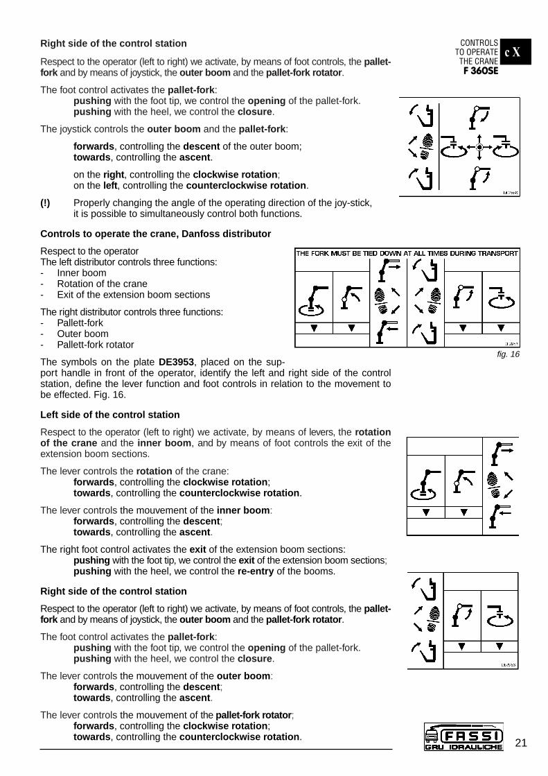
Right side of the control station
Respect to the operator (left to right) we activate, by means of foot controls, the pallet-fork and by means of joystick, the outer boom and the pallet-fork rotator.
The foot control activates the pallet-fork: pushing with the foot tip, we control the opening of the pallet-fork.pushing with the heel, we control the closure.
The joystick controls the outer boom and the pallet-fork:
forwards, controlling the descent of the outer boom;towards, controlling the ascent.
on the right, controlling the clockwise rotation; on the left, controlling the counterclockwise rotation.
(!) Properly changing the angle of the operating direction of the joy-stick,it is possible to simultaneously control both functions.
Controls to operate the crane, Danfoss distributor
Respect to the operatorThe left distributor controls three functions:- Inner boom- Rotation of the crane- Exit of the extension boom sections
The right distributor controls three functions:- Pallett-fork- Outer boom- Pallett-fork rotator
The symbols on the plate DE3953, placed on the sup-port handle in front of the operator, identify the left and right side of the controlstation, define the lever function and foot controls in relation to the movement tobe effected. Fig. 16.
Left side of the control station
Respect to the operator (left to right) we activate, by means of levers, the rotationof the crane and the inner boom, and by means of foot controls the exit of theextension boom sections.
The lever controls the rotation of the crane: forwards, controlling the clockwise rotation;towards, controlling the counterclockwise rotation.
The lever controls the mouvement of the inner boom:forwards, controlling the descent; towards, controlling the ascent.
The right foot control activates the exit of the extension boom sections:pushing with the foot tip, we control the exit of the extension boom sections;pushing with the heel, we control the re-entry of the booms.
Right side of the control station
Respect to the operator (left to right) we activate, by means of foot controls, the pallet-fork and by means of joystick, the outer boom and the pallet-fork rotator.
The foot control activates the pallet-fork: pushing with the foot tip, we control the opening of the pallet-fork.pushing with the heel, we control the closure.
The lever controls the mouvement of the outer boom:forwards, controlling the descent; towards, controlling the ascent.
The lever controls the mouvement of the pallet-fork rotator;forwards, controlling the clockwise rotation;towards, controlling the counterclockwise rotation.
c XCONTROLS
TO OPERATETHE CRANEF 360SE
21
fig. 16
c XCONTROLS TO OPERATETHE CRANEF 360SE
22
Manoeuvres to unfold the crane into a working condition
- Engage the power take off.- Stabilize the vehicle as described on page 16.- Before lifting the inner boom, be sure that the outer ram is open.- Lift the inner boom over the horizontal line, close the outer boom and
eventually extend the booms of the crane. - Operate on the crane rotation to position the fork on the vertical line above
the load, operate on the pallet-fork rotation control for the correct orientationof the fork.
Manoeuvres to fold the crane into the rest condition
- Open the outer boom to its stroke end.- Re-enter the extension boom sections.- Operate the rotation control of the crane and fold the inner boom, paying
attention to the crane boom position on the body. It is necessary duringthis operation to orientate the pallet-fork position to avoid obstacles on thebody or the load.
- Lift and re-enter the outriggers as previously described.- Disengage the power take off.
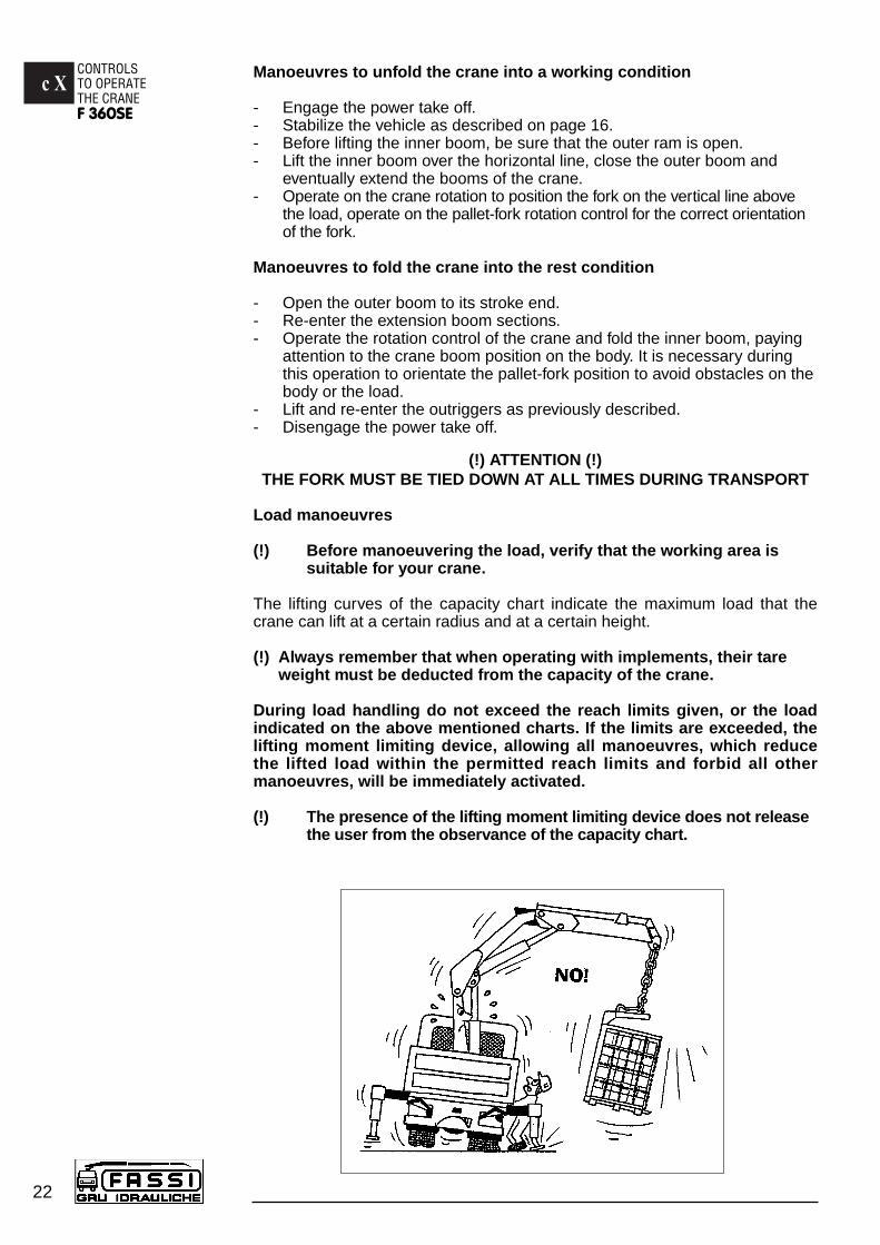
(!) ATTENTION (!)THE FORK MUST BE TIED DOWN AT ALL TIMES DURING TRANSPORT
Load manoeuvres
(!) Before manoeuvering the load, verify that the working area is suitable for your crane.
The lifting curves of the capacity chart indicate the maximum load that thecrane can lift at a certain radius and at a certain height.
(!) Always remember that when operating with implements, their tare weight must be deducted from the capacity of the crane.
During load handling do not exceed the reach limits given, or the loadindicated on the above mentioned charts. If the limits are exceeded, thelifting moment limiting device, allowing all manoeuvres, which reducethe lifted load within the permitted reach limits and forbid all othermanoeuvres, will be immediately activated.
(!) The presence of the lifting moment limiting device does not releasethe user from the observance of the capacity chart.
c XI
23
USE OF IMPLEMENTSF 360SE
USE OF IMPLEMENTS
OIL COOLER (HEAT EXCHANGER)
The crane (available on request) can be equipped with an oil cooler (air-oil heatexchanger) to prevent damage caused by an excessive increase of the oil tempe-rature.
NOTEWhen working in a low temperature climate, we recommend to bring thehydraulic oil up to working temperature prior to starting work, This is bestdone by operating the crane thru all its functions ram stroke end.
(!) WARNING (!)The heat exchanger openings must be kept clear and clean. At no time shouldit be covered.
HYDRAULIC ACCESSORIES
The crane can be provided with implements such as:
- Fork rotator - Pallet-fork
(!) When using an implement it is always necessary to check that its weight,dimension and capacity is matched to the crane performances.
(!) Warning and norms for crane use also apply for hydraulic implement use.
(!) Always remember that when operating with implements, their tare weightmust be deducted from the capacity of the crane.
Hydraulic connections between implements and hoses fitted on theextension boom section of the crane.
(!) In case of hoses connection to implements through coupling unions it isnecessary to verify that there is no trace of soil, curt etc. on the unionsand inside the seats so as to avoid the oil contamination and consequen-tly wear the tightening “ surface of unions.
(!) WARNING (!)To ensure that the control corresponds to the implement movement, hydraulicconnections are symmetrically fitted with coupling unions. Never invert suchpositions: movements inversion as well as operating difficulties could occur.
c XII
24
MAINTENANCE INSTRUCTIONSF 360SE
MAINTENANCE INSTRUCTIONS
To assure a long life to the crane, it is necessary to meticulously follow theinstructions.
General lubrication and small repairs can be carried out by the user; repairs of amore complicated nature must be carried out by authorized service personnel.
Spare parts must be original.
At least once a year you must take the crane to a Fassi Service Center for acheck.
Good maintenance and proper use are imperative to maintain efficient useand guarantee the safety of the crane.
(!) Before disconnecting any hydraulic hoses, ensure that there is no pressurein the hydraulic circuit.
After removing hoses always mark them and their respective ports on the crane.Faulty replacement can cause damage to the rams and to the hydraulic circuit.
Respect the information supplied for maintenance and technical assistance.
Any maintenance operation must be carried out with the crane power source tur-ned off. (in case of fixed mounting with hydraulic power pack, the electric motorhas to be turned off).
Do not place limbs, fingers or any other parts of anatomy into areas of thecrane, which present possibilities of shearing, without having blocked suchparts of the crane.
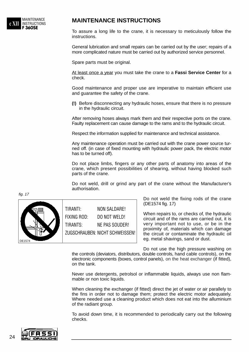
Do not weld, drill or grind any part of the crane without the Manufacturer’sauthorisation.
Do not weld the fixing rods of the crane(DE1574 fig. 17)
When repairs to, or checks of, the hydrauliccircuit and of the rams are carried out, it isvery important not to use, or be in theproximity of, materials which can damagethe circuit or contaminate the hydraulic oileg. metal shavings, sand or dust.
Do not use the high pressure washing onthe controls (deviators, distributors, double controls, hand cable controls), on theelectronic components (boxes, control panels), on the heat exchanger (if fitted),on the tank.
Never use detergents, petrolsol or inflammable liquids, always use non flam-mable or non toxic liquids.
When cleaning the exchanger (if fitted) direct the jet of water or air parallely tothe fins in order not to damage them; protect the electric motor adequately.Where needed use a cleaning product which does not eat into the alluminiumof the radiant group.
To avoid down time, it is recommended to periodically carry out the followingchecks.
fig. 17
TIRANTI: NON SALDARE!
FIXING ROD: DO NOT WELD!
TIRANTS: NE PAS SOUDER!
ZUGSCHRAUBEN: NICHT SCHWEISSEN!DE1574
c XIIMAINTENANCE INSTRUCTIONS
F 360SE
25
Check that all safety devices are efficient.
Check the level of the hydraulic oil in the tank.
Check the hoses fittings and all the components of the hydraulic circuit forpossible leaks.
Check that the oil-diverter - E/S lever can be moved easily.
Check that the crane controls (levers and foot) and the outrigger controls(levers) can be moved easily and return freely to neutral position.
Check the condition of shackles, hooks, wire ropes and every eventually usedequipment.
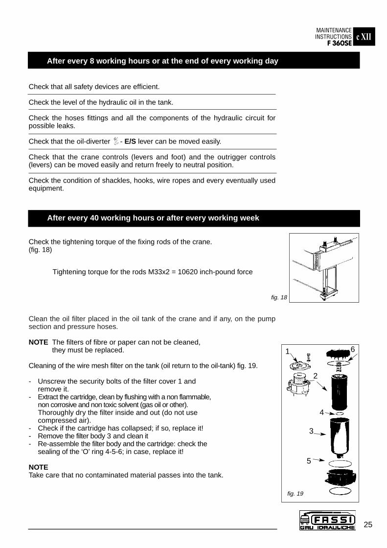
Check the tightening torque of the fixing rods of the crane.(fig. 18)
Tightening torque for the rods M33x2 = 10620 inch-pound force
Clean the oil filter placed in the oil tank of the crane and if any, on the pumpsection and pressure hoses.
NOTE The filters of fibre or paper can not be cleaned, they must be replaced.
Cleaning of the wire mesh filter on the tank (oil return to the oil-tank) fig. 19.
- Unscrew the security bolts of the filter cover 1 and remove it.
- Extract the cartridge, clean by flushing with a non flammable, non corrosive and non toxic solvent (gas oil or other). Thoroughly dry the filter inside and out (do not use compressed air).
- Check if the cartridge has collapsed; if so, replace it!- Remove the filter body 3 and clean it- Re-assemble the filter body and the cartridge: check the
sealing of the ‘O’ ring 4-5-6; in case, replace it!
NOTETake care that no contaminated material passes into the tank.
After every 8 working hours or at the end of every working day
After every 40 working hours or after every working week
1
2
4
3
5
6
fig. 19
fig. 18
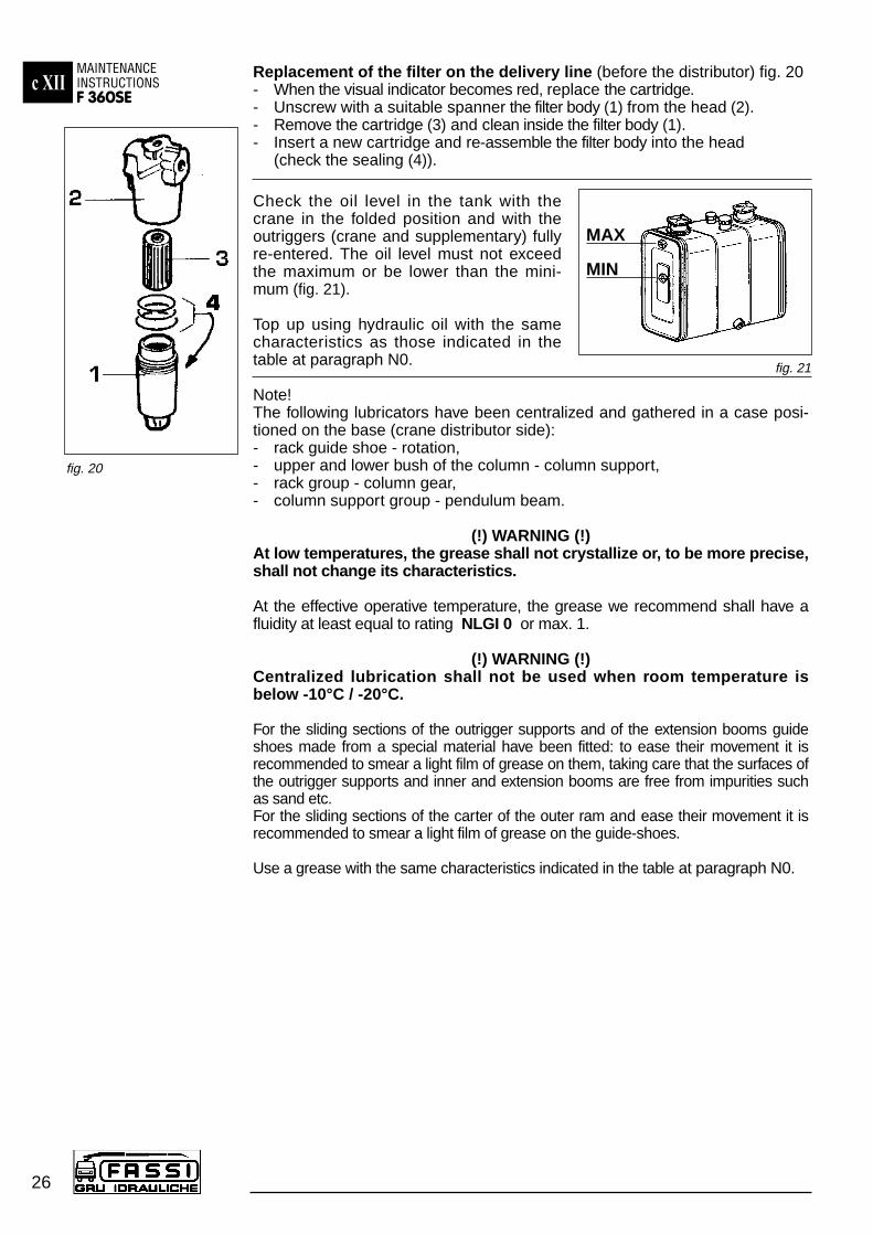
Replacement of the filter on the delivery line (before the distributor) fig. 20- When the visual indicator becomes red, replace the cartridge.- Unscrew with a suitable spanner the filter body (1) from the head (2).- Remove the cartridge (3) and clean inside the filter body (1). - Insert a new cartridge and re-assemble the filter body into the head
(check the sealing (4)).
Check the oil level in the tank with thecrane in the folded position and with theoutriggers (crane and supplementary) fullyre-entered. The oil level must not exceedthe maximum or be lower than the mini-mum (fig. 21).
Top up using hydraulic oil with the samecharacteristics as those indicated in thetable at paragraph N0.
Note!The following lubricators have been centralized and gathered in a case posi-tioned on the base (crane distributor side):- rack guide shoe - rotation,- upper and lower bush of the column - column support, - rack group - column gear,- column support group - pendulum beam.
(!) WARNING (!)At low temperatures, the grease shall not crystallize or, to be more precise,shall not change its characteristics.
At the effective operative temperature, the grease we recommend shall have afluidity at least equal to rating NLGI 0 or max. 1.
(!) WARNING (!)Centralized lubrication shall not be used when room temperature isbelow -10°C / -20°C.
For the sliding sections of the outrigger supports and of the extension booms guideshoes made from a special material have been fitted: to ease their movement it isrecommended to smear a light film of grease on them, taking care that the surfaces ofthe outrigger supports and inner and extension booms are free from impurities suchas sand etc.For the sliding sections of the carter of the outer ram and ease their movement it isrecommended to smear a light film of grease on the guide-shoes.
Use a grease with the same characteristics indicated in the table at paragraph N0.
c XIIMAINTENANCE INSTRUCTIONSF 360SE
26
fig. 21
fig. 20
MAX
MIN

c XIIMAINTENANCE INSTRUCTIONS
F 360SE
27
Check the tightening torque:- of the fixing rods of the crane; consult the following table in order to find it’s
value according to the bolt diameter.
Table of the tightening torques of the fixing rods of the crane on the vehicle.From “C0404 Kit for crane fixing”.
D. Fixing Tighteningrods torque = inch-pound force
M22x1,5 2655M24x2,0 3540M27x2,0 5310M30x2,0 4169M33x2,0 10620M39x3,0 15931
- of the securing bolts for the ram pins and of all the other bolts and screws,where the tightening torque is not expressly indicated, consult the followingtable in order to find it’s value according to the bolt diameter and class.
Table of the bolts tightening torque with average friction value (0,15) and average-good tightening accuracy (C).
Check the guide shoe wear as it affects the sliding section tolerances; if the clea-rances are considerable, damage to the rams and the structure may occur.
Clean the air filter placed in the top of the oil tank filter cap.
Completely replace the hydraulic oil.
(!) The waste oil must be disposed of by authorized persons.
(!) CAUTION DANGER (!)On the outer boom there is a mercury capsule (mercury level switch)duly protected and provided with the following warning stickers.
MERCURY IS EXTREMELY TOXIC. IN CASE OF REPLACEMENTAND/OR SCRAPPING, DISPOSE OF OR RECYCLE THE CAPSU-LE CONTAINING MERCURY WITH MAXIMUM CARE, AND INACCORDANCE WITH THE NATIONAL REGULATIONS IN FORCE.
After every 500 working hours
fig. 22
Bolt inch Class 8.8 Class 10.9 Class 12.9Diameter = D Torque = inch- Torque = inch- Torque = inch-
pound force pound force pound force
0,787 3000 4416 51690,866 4124 6063 70980,945 5169 7594 88861,063 7656 11249 131611,181 10382 15250 178431,299 14108 20728 242511,417 18108 26605 311281,535 23525 34562 40448
From “ELEMENTS DE FIXATION - ASSEMBLAGES VISSES”(AFNOR E 25-030 AGOSTO 1984)
Bolt inch Class 8.8 Class 10.9 Class 12.9Diameter = D Torque = inch- Torque = inch- Torque = inch-
pound force pound force pound force
0,118 9,4 13,8 16,20,157 21,6 31,7 37,10,197 42,7 62,8 73,50,236 73,5 109 1260,315 177 257 3100,394 354 522 6110,472 611 903 10530,551 982 1443 16900,630 1531 2257 26370,709 2115 3115 3646

c XIIMAINTENANCE INSTRUCTIONSF 360SE
27a
Perform: Washing, Function Testing, Testing according to thecapacity plates
Check: Identification plates, Capacity plates
Checklist in accordance with ISO 9927-1
Element Checks to be carried out:
Subframe Tightening torque of the fixing rods, wearStructure and fixing rods and any deformation, actions
Base Lubrication, tightening torque of the rods, Rack group, compensator wear and any deformation, actions
Outriggers Greasing of extension supports, oil-leaks,Supports, rams, base plates wear, actions, inspection of hosessafety catches, hoses
Rotation cylinders Oil-leaks, chromium plating,Cylinders, pistons, seals, any deformation, inspection of hoses
Column Lubrication, wear and any deformation,Inner boom connection, outrigger actionsconnection, pins, bushes
Inner boom Lubrication, wear and any deformation,Pins, outrigger connections actions
Inner ram Oil-leaks, chromium plating, Cylinder, rod, piston, any deformation, inspection of hosesseals, hoses
Outer boom Lubrication, wear and any deformation,Pins, outrigger connections actions
Outer ram Oil-leaks, chromium plating, strains, Cylinder, rod, piston, seals, inspection of hoseshoses
Extension booms Lubrication, wear and any deformation,Guide shoes, pins, actionsoutrigger connections
Extension rams Oil-leaks, chromium plating, Cylinder, rod, piston, seals, any deformation, inspection of hoseshoses
Hydraulic jib Lubrication, wear and any deformation,Booms, pins, outrigger connections actions
Rams (hydraulic jib): Oil-leaks, chromium plating, Cylinder, rod, piston, seals, any deformation, inspection of hoseshoses
Winch Lubrication, wear and any deformation,Torque limiter, brake, actionsrope slide guide, cable, stroke end,pulleis
After every 1000 working hours or after every working year
c XIIMAINTENANCE INSTRUCTIONS
F 360SE
27b
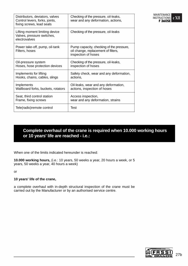
Distributors, deviators, valves Checking of the pressure, oil-leaks,Control levers, forks, joints, wear and any deformation, actions,fixing screws, lead seals
Lifting moment limiting device Checking of the pressure, oil-leaksValves, pressure switches, electrovalves
Power take-off, pump, oil-tank Pump capacity, checking of the pressure, Filters, hoses oil change, replacement of filters,
inspection of hoses
Oil-pressure system Checking of the pressure, oil-leaks,Hoses, hose protection devices inspection of hoses
Implements for lifting Safety check, wear and any deformation, Hooks, chains, cables, slings actions,
Implements Oil-leaks, wear and any deformation, Wallboard forks, buckets, rotators actions, inspection of hoses
Seat, third control station Access inspection, Frame, fixing screws wear and any deformation, strains
Tele(radio)remote control Test
When one of the limits indicated hereunder is reached:
10.000 working hours, (i.e.: 10 years, 50 weeks a year, 20 hours a week, or 5years, 50 weeks a year, 40 hours a week)
or
10 years' life of the crane,
a complete overhaul with in-depth structural inspection of the crane must becarried out by the Manufacturer or by an authorised service centre.
Complete overhaul of the crane is required when 10.000 working hours or 10 years' life are reached - i.e.:
POSSIBLE FAULTSF 360SEc XIII
28
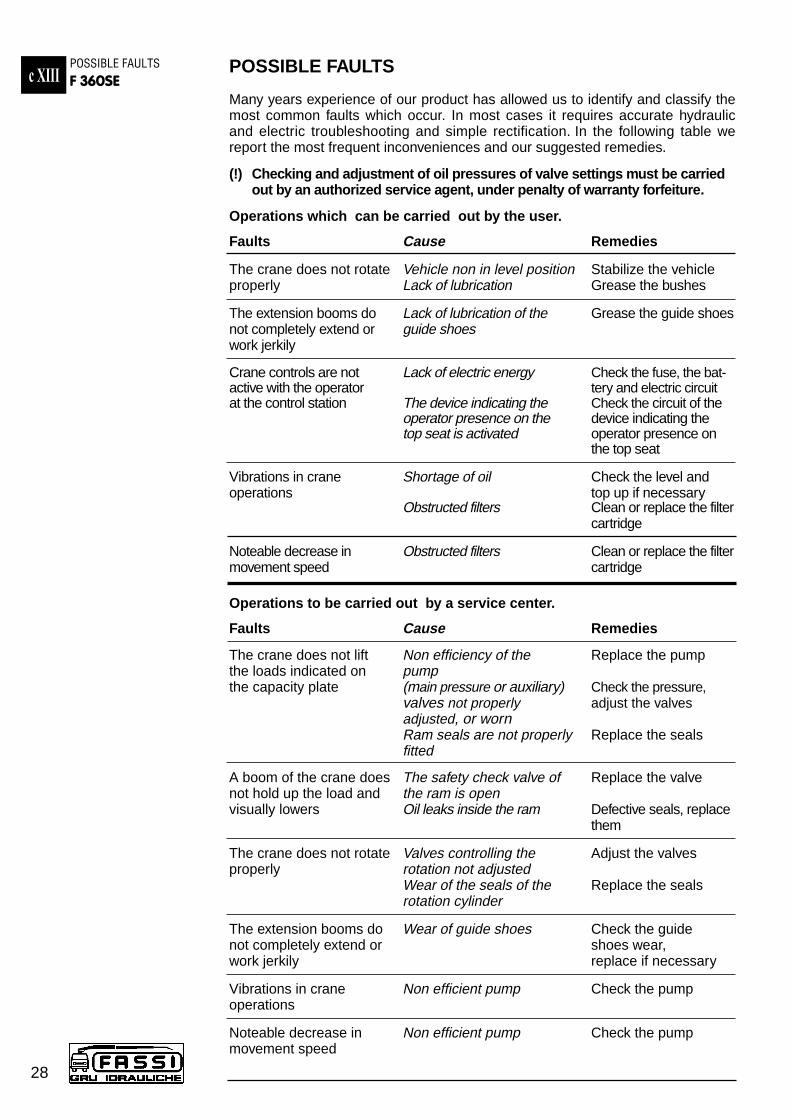
POSSIBLE FAULTS
Many years experience of our product has allowed us to identify and classify themost common faults which occur. In most cases it requires accurate hydraulicand electric troubleshooting and simple rectification. In the following table wereport the most frequent inconveniences and our suggested remedies.
(!) Checking and adjustment of oil pressures of valve settings must be carriedout by an authorized service agent, under penalty of warranty forfeiture.
Operations which can be carried out by the user.
Faults Cause Remedies
The crane does not rotate Vehicle non in level position Stabilize the vehicleproperly Lack of lubrication Grease the bushes
The extension booms do Lack of lubrication of the Grease the guide shoesnot completely extend or guide shoeswork jerkily
Crane controls are not Lack of electric energy Check the fuse, the bat-active with the operator tery and electric circuitat the control station The device indicating the Check the circuit of the
operator presence on the device indicating thetop seat is activated operator presence on
the top seat
Vibrations in crane Shortage of oil Check the level andoperations top up if necessary
Obstructed filters Clean or replace the filtercartridge
Noteable decrease in Obstructed filters Clean or replace the filtermovement speed cartridge
Operations to be carried out by a service center.
Faults Cause Remedies
The crane does not lift Non efficiency of the Replace the pumpthe loads indicated on pumpthe capacity plate (main pressure or auxiliary) Check the pressure,
valves not properly adjust the valvesadjusted, or wornRam seals are not properly Replace the sealsfitted
A boom of the crane does The safety check valve of Replace the valvenot hold up the load and the ram is openvisually lowers Oil leaks inside the ram Defective seals, replace
them
The crane does not rotate Valves controlling the Adjust the valvesproperly rotation not adjusted
Wear of the seals of the Replace the sealsrotation cylinder
The extension booms do Wear of guide shoes Check the guide not completely extend or shoes wear, work jerkily replace if necessary
Vibrations in crane Non efficient pump Check the pumpoperations
Noteable decrease in Non efficient pump Check the pumpmovement speed

c XIVHYDRAULIC AND
ELECTRIC SCHEMATICSF 360SE
29
HYDRAULIC AND ELECTRIC SCHEMATICS
Hydraulic schematic for crane - two standard distributors - lifting moment limitingdevice “intelligent” type
CODE DESCRIPTION
DI490 DISTRIBUTORDV011 DEVIATOREV110 ELECTROVALVEFI776 FILTERFI854 FILTERM1/M GAUGE QUICK CONNECTIONPR103 PRESSURE SWITCHRU973 FAUCETRU976 FAUCET
VA102 DOUBLE EFFECT BLOCK VALVEVA177 ANTIBURST VALVE FOR LIFTING RAMSVA194 DOUBLE EFFECT BLOCK VALVEVA208 UNIDIRECTIONAL VALVEVA209 SIMPLE EFFECT BLOCK VALVEVA214 LIFTING MOMENT LIMITING DEVICE VALVEVA222 OIL FLOW REGULATOR VALVE FOR ROTATION
CYLINDERVA238 SIMPLE EFFECT BLOCK VALVE

Hydraulic schematic for crane - two Danfoss distributors - lifting moment limitingdevice “intelligent” typec XIV
HYDRAULIC AND ELECTRIC SCHEMATICSF 360SE
30
SYMBOL DESCRIPTON
DI490 DISTRIBUTORDV011 DEVIATOREV109 ELECTROVALVEFI776 FILTERFI854 FILTERM1/M GAUGE QUICK CONNECTIONRU971 FAUCETRU976 FAUCETVA102 DOUBLE EFFECT BLOCK VALVEVA177 ANTIBURST VALVE FOR LIFTING RAMS
VA185 SELECTOR VALVEVA194 DOUBLE EFFECT BLOCK VALVEVA209 SIMPLE EFFECT BLOCK VALVEVA224 LIFTING MOMENT LIMITING DEVICE VALVEVA225 LEVEL SENSOR VALVEVA227 SEQUENCE VALVEVA232 UNIDIRECTIONAL VALVEVA239 SIMPLE EFFECT BLOCK VALVEVA247 DOUBLE EFFECT BLOCK VALVE
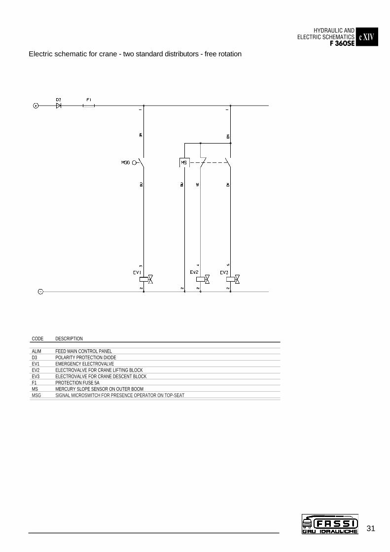
Electric schematic for crane - two standard distributors - free rotation
c XIVHYDRAULIC AND
ELECTRIC SCHEMATICSF 360SE
31
CODE DESCRIPTION
ALIM FEED MAIN CONTROL PANELD3 POLARITY PROTECTION DIODEEV1 EMERGENCY ELECTROVALVEEV2 ELECTROVALVE FOR CRANE LIFTING BLOCKEV3 ELECTROVALVE FOR CRANE DESCENT BLOCKF1 PROTECTION FUSE 5AMS MERCURY SLOPE SENSOR ON OUTER BOOMMSG SIGNAL MICROSWITCH FOR PRESENCE OPERATOR ON TOP-SEAT
c XIV
32
HYDRAULIC AND ELECTRIC SCHEMATICSF 360SE
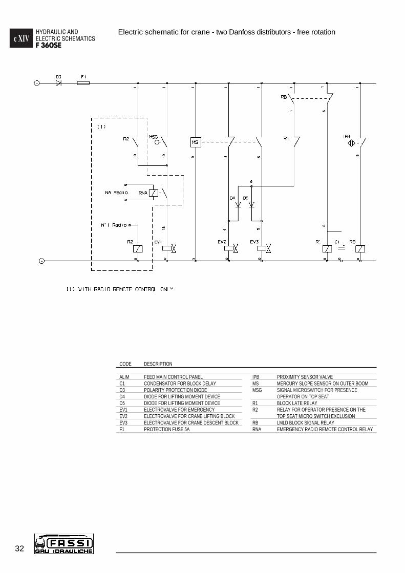
Electric schematic for crane - two Danfoss distributors - free rotation
CODE DESCRIPTION
ALIM FEED MAIN CONTROL PANELC1 CONDENSATOR FOR BLOCK DELAYD3 POLARITY PROTECTION DIODED4 DIODE FOR LIFTING MOMENT DEVICED5 DIODE FOR LIFTING MOMENT DEVICEEV1 ELECTROVALVE FOR EMERGENCYEV2 ELECTROVALVE FOR CRANE LIFTING BLOCKEV3 ELECTROVALVE FOR CRANE DESCENT BLOCKF1 PROTECTION FUSE 5A
IPB PROXIMITY SENSOR VALVEMS MERCURY SLOPE SENSOR ON OUTER BOOMMSG SIGNAL MICROSWITCH FOR PRESENCE
OPERATOR ON TOP SEATR1 BLOCK LATE RELAYR2 RELAY FOR OPERATOR PRESENCE ON THE
TOP SEAT MICRO SWITCH EXCLUSIONRB LMLD BLOCK SIGNAL RELAYRNA EMERGENCY RADIO REMOTE CONTROL RELAY
c XIVHYDRAULIC AND
ELECTRIC SCHEMATICSF 360SE
33
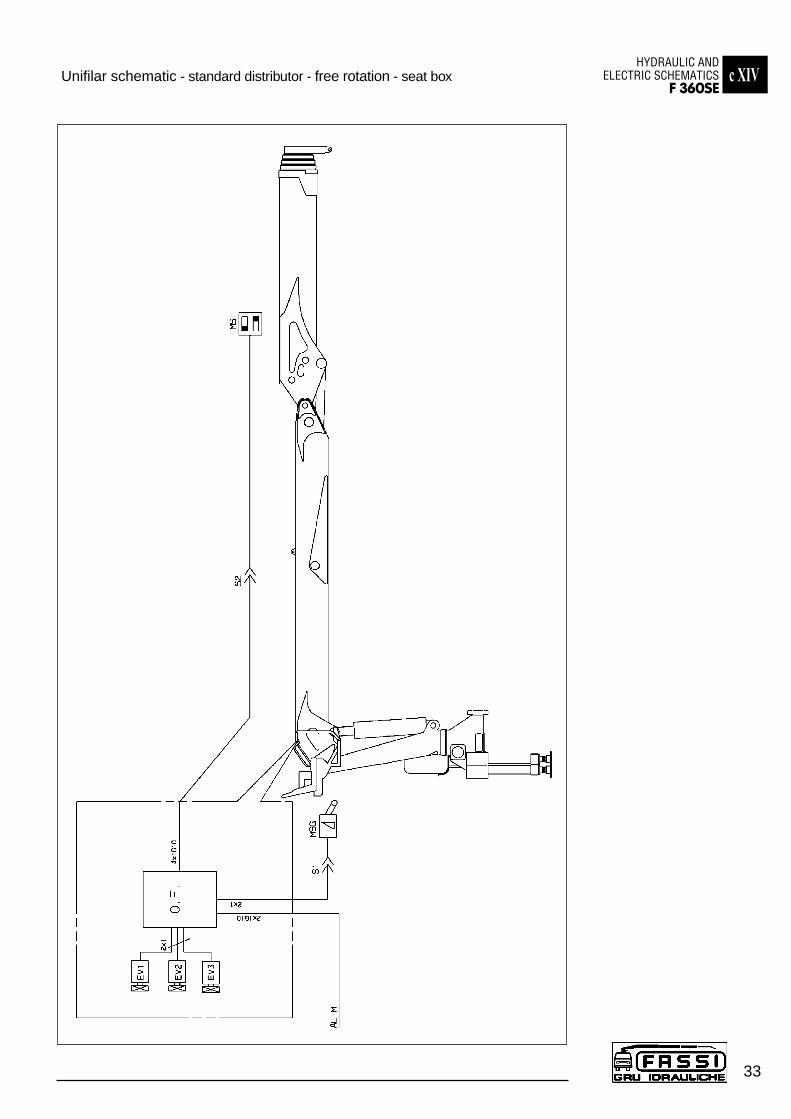
Unifilar schematic - standard distributor - free rotation - seat box
c XIVHYDRAULIC AND ELECTRIC SCHEMATICSF 360SE
34
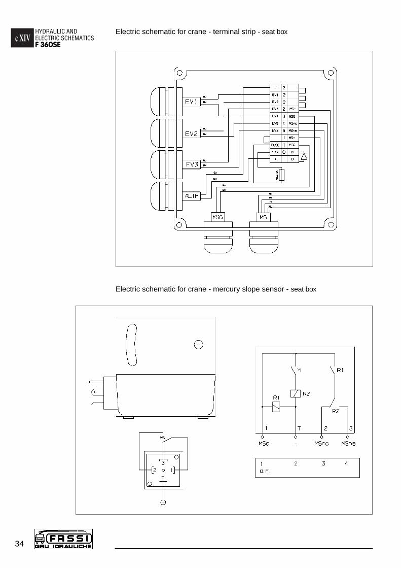
Electric schematic for crane - terminal strip - seat box
Electric schematic for crane - mercury slope sensor - seat box

c XVTABLE OF HYDRAULIC OIL AND LUBRICANTS
CHARACTERISTICSF 360SE
35
TABLE OF HYDRAULIC OIL AND LUBRICANTS CHARACTERISTICS
HYDRAULIC OIL WITH HIGH VISCOSITY: ISO-L-HV
Minimal external maximal oil Gradationtemperature: temperature:
-35°C +45°C ISO VG 32-20°C +75°C ISO VG 46
HYDRAULIC OIL WEAR RESISTANT: ISO-L-HM
Minimal external maximal oil Gradationtemperature: temperature:
-10°C +60°C ISO VG 32+ 0°C +75°C ISO VG 46+ 5°C +85°C ISO VG 68+10°C +90°C ISO VG 100
GREASE (for centralized system)
Use only GREASE NILEX EP1 of the firm NILS.NOTE: Do not ABSOLUTELY mix different types of grease.
GREASE (for slew ring, extension booms, outrigger supports...)
-30°C up to +130°C EP1 Gradation (cold climate)EP2 Gradation (warm climate)
All grease used must be free from acid and resin, not hygroscopic and long-life such as
BP GREASE LTX-EP1\EP2 or ELF EPEXA 1\2ESSO BEACON EP1\EP2 or TEXACO EP1\EP2
MOBIL EP1\EP2 or SIMILAR.
HYDRAULIC OIL FOR MOTOREDUCER
Classification ISO-L-CC
Gradation EP ISO-VG 150
LUBRICATING OIL (for winch cable)
The most suitable here is a general-purpose lubricating oil with about SAE30° viscosity. A lubricating oil containing non-stick additives is recommendedif the cables are expected to move quickly through the pulleys.
BRILUBE 50 (BRITISH ROPES - BRINDON)
( ! ) WARNING ( ! ) Don’t use greases with solid particles as “Bisulphide of Molybdenum”(not compatible with eventual teflon bushes).
A
36
INSTRUCTION AND WARNING PLATESF 360SE
INSTRUCTION AND WARNING PLATES
DE 2676Instruction plate and safety norms
DE 2327Warning plate to stabilize the vehiclebefore using the crane
DE 2600 DE 2601
DE 2498
Instruction plates to stabilize the vehicle
DE 2497
Warning plates to make sure that no one is or transits in close proximity of the outriggers

37
AINSTRUCTION AND WARNING PLATES
F 360SE
Crane controls plate
DE 3953
DE 2868
DE 2100 Danger plate for crushing of lower limbs
DE 1067Do not walk or stay under a suspendedload and for unauthorized persons to bewithin the working area.DE1067
A
38
INSTRUCTION AND WARNING PLATESF 360SE
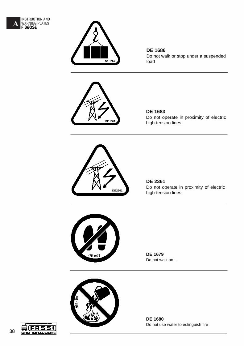
DE 1679Do not walk on...
DE 1680Do not use water to estinguish fire
DE 1686Do not walk or stop under a suspendedload
DE 1683Do not operate in proximity of electrichigh-tension lines
DE 2361Do not operate in proximity of electrichigh-tension linesDE2361
AINSTRUCTION AND WARNING PLATES
F 360SE
39
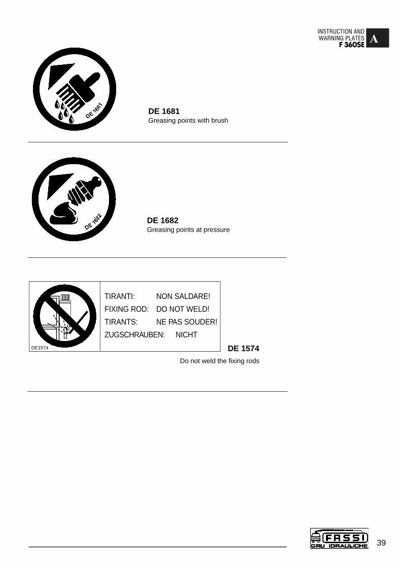
DE 1682 Greasing points at pressure
DE 1681 Greasing points with brush
Do not weld the fixing rods
DE 1574
TIRANTI: NON SALDARE!
FIXING ROD: DO NOT WELD!
TIRANTS: NE PAS SOUDER!
ZUGSCHRAUBEN: NICHT
DE1574
BCAPACITY PLATESF 360SE.24
40
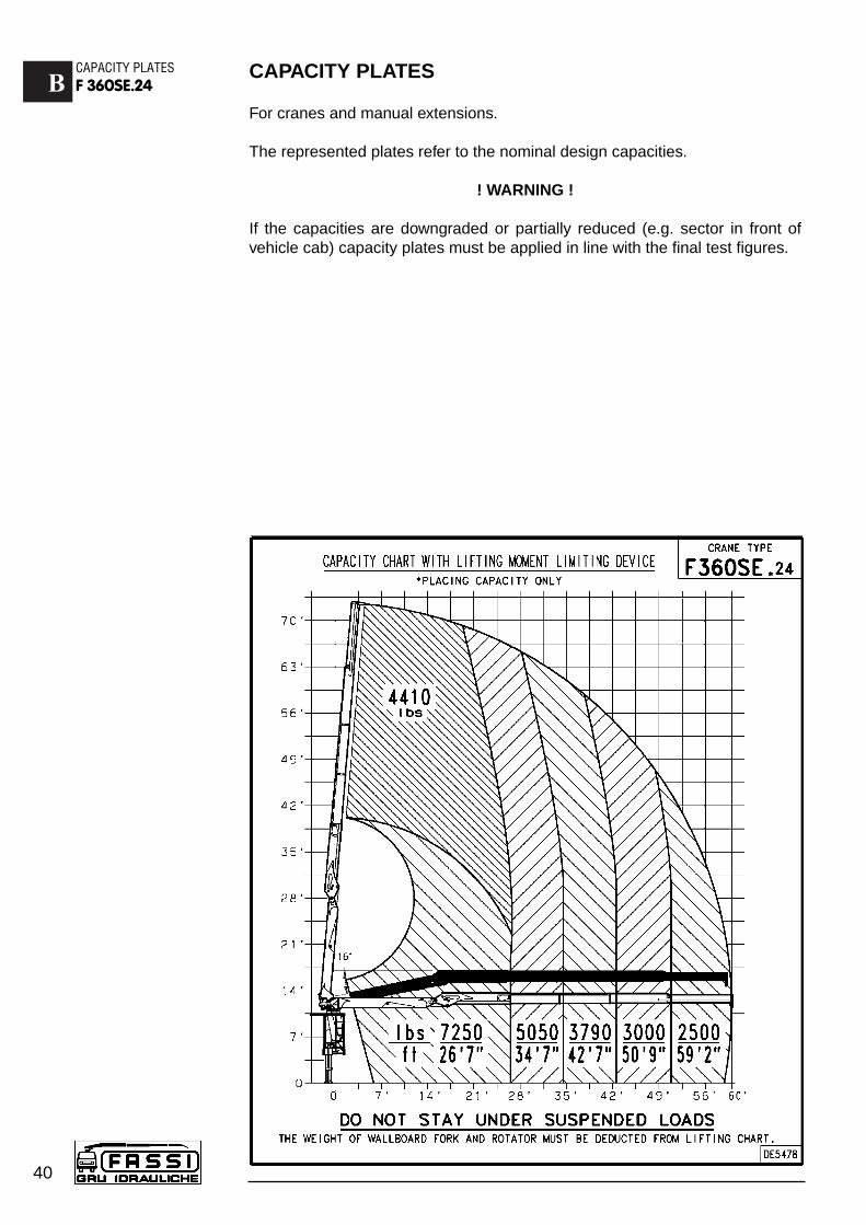
CAPACITY PLATES
For cranes and manual extensions.
The represented plates refer to the nominal design capacities.
! WARNING !
If the capacities are downgraded or partially reduced (e.g. sector in front ofvehicle cab) capacity plates must be applied in line with the final test figures.