Embed Size (px)
Citation preview

1
FASSI CRANE
F 170A.23 use and maintenanceFROM SERIAL NUMBER *3001*
INDEX OF PARAGRAPHSA0 INTRODUCTIONB0 SAFETY NORMSC0 WARNING AND INSTRUCTIONSC0.1 Before operatingC0.2 During operationC0.3 At the end of the operation (Prior to driving the vehicle)D0 CLASSIFICATION OF THE CRANE MODELD0.1 Technical dataD1 IDENTIFICATION OF THE CRANE MODELD1.1 Crane mark D1.2 Crane markE0 CRANE NOMENCLATUREE0.1 Crane with ground controls and (on request) Crane with ground controls
and with top seat controls by hand cables E0.2 Crane with top seat controls and with ground controls for outriggersF0 NOMENCLATURE OF THE SAFETY AND PROTECTION DEVICESF0.1 Crane with ground controls and (on request) Crane with ground controls
and with top seat controls by hand cablesF0.2 Crane with top seat controls and with ground controls for outriggersF1 NOMENCLATURE OF THE SAFETY AND PROTECTION DEVICESF1.1 Crane with ground controls and (on request) Crane with ground controls
and with top seat controls by hand cablesF1.2 Crane with top seat controls and with ground controls for outriggersG0 SUPPLEMENTARY BEAMSG0.1 Identification of the supplementary beamsG1 TILTABLE OUTRIGGER RAMSG2 MANOEUVRES AND CONTROLS TO STABILIZE THE VEHICLEG2.1 Supplementary beam; manual extension of the outrigger supportsG2.2 Functions of control levers for stabilizationG2.3 Controls to stabilize the vehicleG2.4 Bilateral controls to stabilize the vehicleH0 CONTROLS TO OPERATE THE CRANEH0.1 Manoeuvres to unfold the crane into a working conditionH0.2 Manoeuvres to fold the crane into the rest condition
Edition 25.09.2000

H0.3 Manoeuvres to unfold the crane "C" into a working conditionH0.4 Manoeuvres to fold the crane "C" into the rest condition
H1 MANOEUVRES OF THE CRANE LOADSH1.1 Lifting moment limiting device “intelligent type”H1.2 Lifting moment limiting device for two working sectors (optional)H1.3 Control panelsH1.4 Reactivation button of crane functions with standard distributor in the
absence of the electric power H1.5 Emergency exclusion screw of the lifting moment limiting device
(crane with standard distributor)H1.6 Emergency tap lever of the lifting moment limiting device
(crane with Danfoss distributor)H1.7 Rotation limiting device
H2 MANOEUVRES OF THE CRANE LOADSH2.1 Load limiting deviceH2.2 Lifting moment limiting device “intelligent type” (optional)H2.3 Reactivation button of crane functions with standard distributor in the
absence of the electric power H2.4 Emergency exclusion screw of the lifting moment limiting device
(crane with standard distributor)H2.5 Emergency tap lever of the lifting moment limiting device
(crane with Danfoss distributor)
L0 USE OF IMPLEMENTSL0.1 Hydraulic connections for implements - supplementary hosesL1 MANUAL EXTENSIONSL2 CONTROLS TO OPERATE THE HYDRAULIC IMPLEMENTS OF THE CRANE
L3 WINCHL3.1 Winch for craneL3.2 Winch for crane
L4 HYDRAULIC JIBSL4.1 Identification of the hydraulic jibL4.2 Nomenclature of the hydraulic jibL4.3 Manoeuvres to unfold the jib in working conditionL4.4 Manoeuvres to fold the jib in rest conditionL4.5 Operations to remove the hydraulic jib from the craneL4.6 Operations to mount the hydraulic jib on the crane
M0 MAINTENANCE INSTRUCTIONSM0.1 At the end of every working dayM0.2 After the first 40 hours useM0.3 After every working weekM0.4 After every 500 working hoursM0.4 Complete overhaul of the craneN0 TABLE OF HYDRAULIC OIL and lubricants characteristics
P0 POSSIBLE FAULTSP0.1 Operations which can be carried out by the userP0.2 Operations to be carried out by a service centerR0 INSTRUCTION AND WARNING PLATESS0 HYDRAULIC SCHEMATICS FOR CRANES1 HYDRAULIC SCHEMATICS FOR CRANET0 ELECTRIC SCHEMATICS FOR CRANET1 ELECTRIC SCHEMATICS FOR CRANE
V0 CAPACITY PLATES FOR CRANE WITH LIFTING MOMENT LIMITING DEVICE
V1 CAPACITY PLATES FOR CRANE WITHOUTLIFTING MOMENT LIMITING DEVICE2

FASSI CRANE
F 170A.23use and maintenance
THANK YOU FOR SELECTING ONE OF FASSI CRANES.
This crane is the result of FASSI philosophy: ongoing research, rigoroustesting, data verification, and analysis of performances.
Many years of experience has allowed us to grant you the maximum safety ofoperation together with the optimization of machine performances.
All this represents the core of FASSI quality system.
FASSI quality system is in conformity withUNI EN ISO 9001 - ISO 9001.
The fitment of the crane on the vehicle must be carried out in accordance withthe instructions given by FASSI in the manual for hydraulic crane fitting andthe relevant chassis manufacturers directives.
The Manufacturer declines all responsibility and guarantee if the fitting isentrusted to workshops without sufficient technical capability to carry out thework in conformity.
Be sure that the unit has been installed, inspected and tested in accordancewith the local legal requirements.
As well as the principal safety norms, this manual contains a description of thecrane and the instructions for use and maintenance.
The following instructions refer to mobile cranes in general and must be integratedwith the manual for use supplied by the centre responsible for the crane fitting ontruck, vehicle or other type of structure.
READ THIS MANUAL CAREFULLY prior to use or any maintenance. A few minu-tes spent now could save time and labour later.
Always conform to the safety norms and the instructions for use and maintenancecontained in the present manual in order to guarantee a long life to the crane.
FASSI GRU IDRAULICHENOTE
All the paragraphs marked by the symbol refer to components requiredwithin the europen community.
The above-said components may be optional in other countries in accor-dance with the national regulations in force.
NOTEThe original version of the present manual is in italian.
A0INTRODUCTION
F 170A.23
3

B0 SAFETY NORMS
Strictly conform to the norms reported by the plates DE4236 (fig. 1) placednext to the controls, in order to avoid possible accidents while operating thecrane.
Only authorized persons are allowed to operate the crane.
The crane must be used on firm, level ground.
Check that the vehicle hand brake is on and that the wheels are chocked.
Before every operation make sure that:- no-one is within the working area of the crane;- the safety devices are in place and operative; - the minimum safe working distances from power lines are observed;- the load is correctly slung and hooked.
Stabilize the vehicle by the outrigger rams, making sure that:- the lateral supports are fully extended;- the wheels are in contact with the ground and the suspension is not
completely unloaded.
Use the crane in accordance with the use and maintenance manual, making sure that: - the load and radius are within the maximum limits shown on the
crane capacity plate;- the crane is used progressively avoiding sudden load movements- swinging or dragging of the load is avoided;- the load is lifted before rotating.
When using implements protect the crane working area with a barrier.
The vehicle/crane are not left unless the power take off is disengaged and theload is on the ground.
Before driving the vehicle make sure that the outriggers are fully retracted andre-entered, the safety taps closed and the crane is in folded position.
B0SAFETY NORMSF 170A
4
fig. 1

C0 WARNING AND INSTRUCTIONS
The use of the crane is reserved to authorized personnel, instructed in advance,who has to conform to the safety norms and instructions contained in the usemanual supplied with the crane. (See norms ISO 9926-1)
It is absolutely prohibited to walk or stop under a suspended load
It is prohibited for unauthorized persons to be within the working area.
Under no circumstances interfere with the safety and protection devices.
Warning plates, as well as instruction and operation plates must be replacedwhen no longer readable or missing. See Paragraph R0 Instruction and warningplates.
Do not use the outriggers to raise the vehicle.
To avoid hitting bridges or tunnels check and record the overall height of yourcrane in the folded position or in laid position in the body or on the load. Alwaysrespect and pay proper attention to road signs placed in proximity of suchobstacles.
C0.1 Before operating
(!) ATTENTION (!)Check that protections are in their place and that all safety devices are fittedand active. (See norms ISO 9927-1)
Keep the ladder and the control station on the top seat, clean; the seat can tiltforward.
Make sure that control stations are properly lit so as to ensure safety while opera-ting and allow instruction plates to be visible.
Check that the working area is adequate and pro-perly lighted for your crane.
Make sure that the hook is always free to rotate onits pin and that nothing obstructs its vertical positio-ning.
Check the efficiency of the hook safety catch.
Carefully inspect the condition of ropes or chains.
Make sure that the pallet fork is connected to the crane hook by means of a chainhaving at least three (3) rings.
C0.2 During operation
Take the vehicle fumes away from the working area by fitting an extension tube ofa suitable diameter to the exhaust system.Do not run the engine in a indoor area without first making sure there is adequateventilation.
When using the ladder to reach the control station on the top seat, avoid knockinginto the controls while going up or down the ladder. The control station on the top seat is provided with side safety guards; stay withinthese guards.
Make sure that no one is within the working area of the crane.
Avoid swinging the load above working and transit areas; any hidden dangersituation must be audibly alarmed.
C0WARNING AND INSTRUCTIONS
F 170A
5
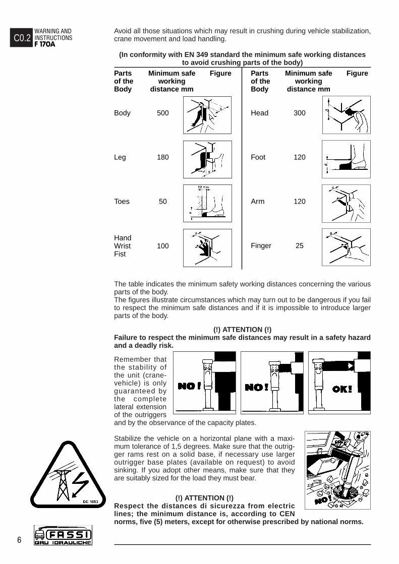
Avoid all those situations which may result in crushing during vehicle stabilization,crane movement and load handling.
(In conformity with EN 349 standard the minimum safe working distances to avoid crushing parts of the body)
The table indicates the minimum safety working distances concerning the variousparts of the body.The figures illustrate circumstances which may turn out to be dangerous if you failto respect the minimum safe distances and if it is impossible to introduce largerparts of the body.
(!) ATTENTION (!)Failure to respect the minimum safe distances may result in a safety hazardand a deadly risk.
Remember thatthe stability ofthe unit (crane-vehicle) is onlyguaranteed bythe completelateral extensionof the outriggersand by the observance of the capacity plates.
Stabilize the vehicle on a horizontal plane with a maxi-mum tolerance of 1,5 degrees. Make sure that the outrig-ger rams rest on a solid base, if necessary use largeroutrigger base plates (available on request) to avoidsinking. If you adopt other means, make sure that theyare suitably sized for the load they must bear.
(!) ATTENTION (!)Respect the distances di sicurezza from electriclines; the minimum distance is, according to CENnorms, five (5) meters, except for otherwise prescribed by national norms.
C0.2WARNING AND INSTRUCTIONSF 170A
6
Parts Minimum safe Figureof the workingBody distance mm
Body 500
Leg 180
Toes 50
Hand Wrist 100Fist
Parts Minimum safe Figureof the workingBody distance mm
Head 300
Foot 120
Arm 120
Finger 25

(!) ATTENTION (!)Failure to respect the minimum safe distan-ces may result in electrical hazards for theoperator and his assistants.
(!) ATTENTION (!)Do not utilize the crane with wind speedexceeding 12,5 m\s (value 6 of the Beaufortscale).
Indications about wind speed
Force of the Wind speed Classification Characteristicswind m/sBeaufort scale
0 0,0 - 0,2 Calm Calm wind, smoke goes upquite vertically
1 0,3 - 1,5 Light breeze Smoke reveals the direction2 1,6 - 3,3 of the wind, one can feel the
wind blowing, leaves start fluttering.
3 3,4 - 5,4 Moderate breeze Leaves and branches are4 5,5 - 7,9 in constant motion, small
branches start fluttering. Dust and papers dance onthe ground.
5 8,0 - 10,7 Fresh breeze Small green branches bend, the surface of waterways andlakes are wavy.
6 10,8 - 13,8 Near gale Big branches bend, wind whistles through high-tensioncables, it's difficult to walkkeeping the umbrella open.
7 13,9 - 17,1 Moderate gale Trees sway, it's hard to walk.
8 17,2 - 20,7 Storm wind Branches get broken, it's hard to walk.
9 20,8 - 24,4 Storm It damages houses (antennasand roof tiles fall down)
(!) ATTENTION (!)Carefully inspect the load rigging.
Hook up the load, checking that it does not exceed the capacity indicated on thelifting diagram specific to each load configuration.
Make sure that the lifted load is balanced.
Avoid swinging the load above the control station; incases where the load is too close, the crane must beoperated from the opposite side.
When operating through a winch, lift the load verticallyusing the cable and not the booms in order to avoidswinging the load.
C0.2WARNING AND INSTRUCTIONS
F 170A
7
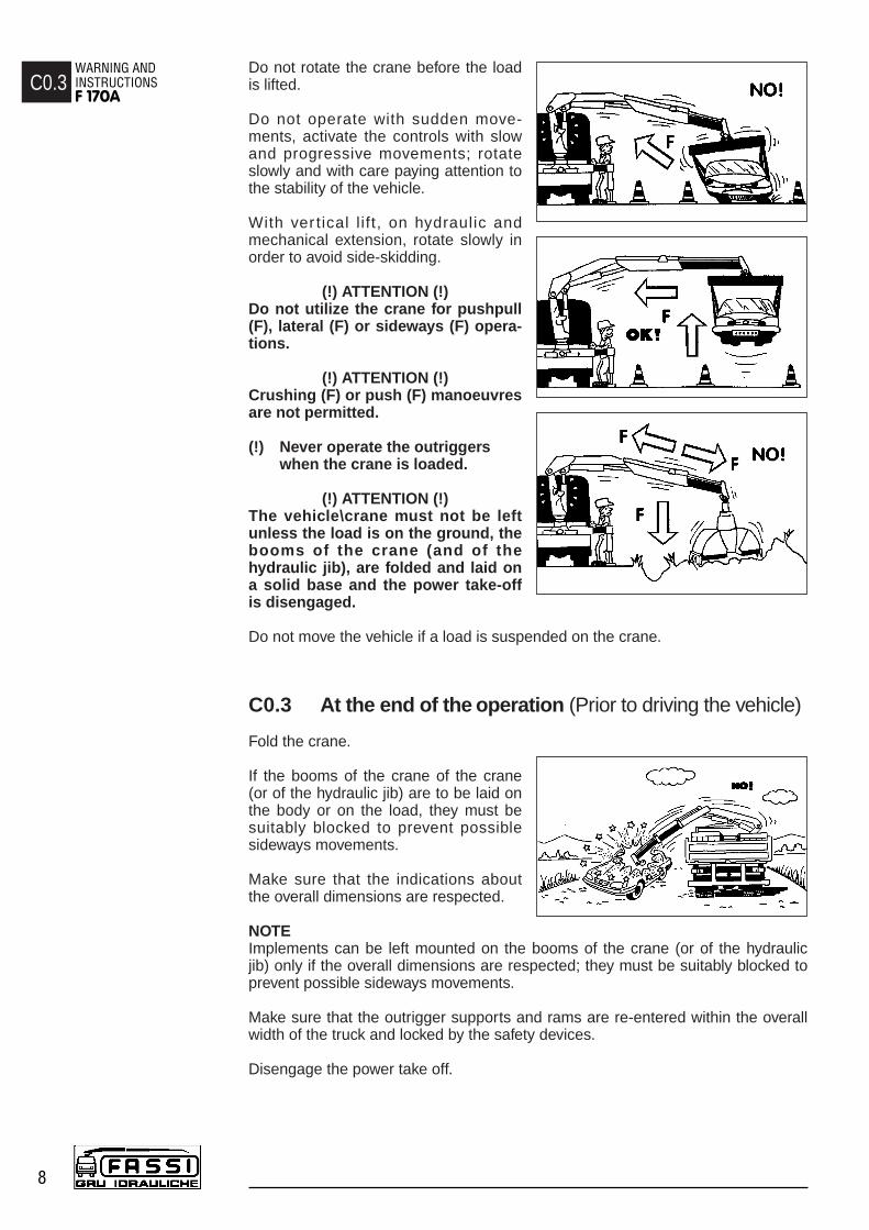
Do not rotate the crane before the loadis lifted.
Do not operate with sudden move-ments, activate the controls with slowand progressive movements; rotateslowly and with care paying attention tothe stability of the vehicle.
With ver tical l i ft, on hydraulic andmechanical extension, rotate slowly inorder to avoid side-skidding.
(!) ATTENTION (!)Do not utilize the crane for pushpull(F), lateral (F) or sideways (F) opera-tions.
(!) ATTENTION (!)Crushing (F) or push (F) manoeuvresare not permitted.
(!) Never operate the outriggerswhen the crane is loaded.
(!) ATTENTION (!)The vehicle\crane must not be leftunless the load is on the ground, thebooms of the crane (and of thehydraulic jib), are folded and laid ona solid base and the power take-offis disengaged.
Do not move the vehicle if a load is suspended on the crane.
C0.3 At the end of the operation (Prior to driving the vehicle)
Fold the crane.
If the booms of the crane of the crane(or of the hydraulic jib) are to be laid onthe body or on the load, they must besuitably blocked to prevent possiblesideways movements.
Make sure that the indications aboutthe overall dimensions are respected.
NOTEImplements can be left mounted on the booms of the crane (or of the hydraulicjib) only if the overall dimensions are respected; they must be suitably blocked toprevent possible sideways movements.
Make sure that the outrigger supports and rams are re-entered within the overallwidth of the truck and locked by the safety devices.
Disengage the power take off.
C0.3WARNING AND INSTRUCTIONSF 170A
8

D0 CLASSIFICATION OF THE CRANE MODEL
The design of this crane has been carried out in respect of DIN 15018 norms,fatigue test classification H1B3.
The crane can operate, intermittently, with lifting devices other than the hook.
The dimensions and the capacity of the implements must be proportioned withcrane performances.
D0.1 Technical data
D0CLASSIFICATION OF THE CRANE MODEL
F 170A.23
9
ST 170
F170A.23
F 170A.23
Lifting Standard Hydraulic Rotation Rotation Working Pump Oil tank Crane Max. workingcapacity reach extension arc torque pressure capacity capacity weight pressure
on the outrigger(Φ 200)
15,39 tm 10,40 m 5,75 m 400° 2,86 tm 29,5 MPa 40 l/min 120 l 2305 kg 30 daN\cm2
151,0 kNm 28,1 kNm

D0.1CLASSIFICATION OF THE CRANE MODELF 170A.23
10
ST 170
MASSIMA ALTEZZA SOTTOGANCIO.
HAUTEUR MAXIMUM SOUS CROCHET.
MAXIMUM HOOKING POSITION.
MAXIMALHOEHE BIS KRANHAKEN.
ST 170
— MEZZERIA TIRANTI
— FIXING ROD CENTER DISTANCE
— LIGNE MEDIANE TIRANTS
— ABMESSUNG DER BEFESTIGUNGSBRIDEN
M24 x 2
1395 4’ 7’’5010 16’ 5’’780 4’ 7’’
ABC
STANDARD
1705 5’ 7’’5630 18’ 6’’765 2’ 6’’
ABC
EXTRA
2040 6’ 8’’6300 20’ 8’’765 2’ 6’’
ABC
SUPER-EXTRA
F170A.23
F170A

D1 IDENTIFICATION OF THE CRANE MODEL
The exact crane model, serial number and description of implements willenable FASSI Service Department to give a rapid and efficient response.
D1.1 Crane mark
The CE indicates that the crane complies with the MachinesDirective (D.M.) 98/37; it can be considered effective onlywith a written declaration of conformity enclosed. The craneaffixed with the CE mark is supplied with a lifting momentlimiting device to preserve the crane structure from over-loads.
Identification data are marked on the plate DE1661 used forthe CE mark (fig. 2) and fixed on the base
1 - Crane model2 - Serial Number3 - Year of manufacturing
The crane must not be put into service within the European Community unlessthe machine on which it is mounted also conforms with the prescribed Directive.Ever change of use, modification or addition of accessories, not specifiedby this manual must be affixed with a new CE mark in accordance with theMachinery Directive.
A further metallic plate (fig. 3) fixed to the crane by the installer,quotes the identifying data of the equipment and the final CEmark.
1 - Name of the installer who applied the finalCE mark
2 - Crane mark, model and serial number3 - Vehicle mark, model and chassis number4 - Year of mounting
D1.2 Crane mark
Identification data of the crane are marked on the plateDE2141 and fixed on the base. (fig. 4)
1 - Crane model2 - Serial Number3 - Year of manufacturing
(!) UNDER NO CIRCUMSTANCES SHOULD THE DATA MARKED ON THE PLATES BE ALTERED.
D1IDENTIFICATION OFTHE CRANE MODEL
F 170A
11
fig. 2
fig. 4
2
1
3
2
1
3
fig. 3
CRANE - MARK AND MODEL SERIAL NUMBER
TRUCK - MARK AND MODEL TRUCK FRAME SERIAL NUMBER
YEAR OF MOUNTING
2
3
1
4

E0 CRANE NOMENCLATURE
E0.1 Crane with ground controls.Crane with ground controls and with top seatcontrols by hand cables (on request) (fig. 5).
Pos. Description
1. Outrigger rams2. Outrigger supports 3. Base4. Rotation cylinders5. Deviator crane - outriggers6. Dual control for deviator crane - outriggers7. Multifunction deviator8. Multifunction transmission9. Distributor bank10. Double control11. Column12. Inner ram13. Inner boom14. Outer ram15. Outer boom16. Booms extension rams17. Extension boom sections18. Lifting hook19. Oil tank20. Manual extensions (optional)21. Seat (optional)22. Hand-cables for crane (optional)
E0.2 Crane with top seat controls and with ground controls for outriggers. (fig. 6)
Pos. Description
1. Outrigger rams2. Outrigger supports 3. Base4. Rotation cylinders5. Deviator crane - outriggers6. Dual control for deviator crane - outriggers7. Multifunction deviator8. Multifunction transmission9. Column10. Seat11. Distributor bank12. Inner ram13. Inner boom14. Outer ram15. Outer boom16. Booms extension rams17. Extension boom sections18. Lifting hook19. Oil tank20. Manual extensions (optional)
E0CRANE NOMENCLATURE F 190A
12

E0CRANE
NOMENCLATURE F 170A
13
fig. 5
fig. 6

F0NOMENCLATURE OF THE SAFETY AND PROTECTION DEVICESF 170A
14
F0 NOMENCLATURE OF THE SAFETY ANDPROTECTION DEVICES
F0.1 Crane with ground controls.Crane with ground controls and with top seatcontrols by hand cables (on request) (fig. 7).
Pos. Description
1. Check valves for outrigger rams2. Check valves for rotation control (flow regulators)3. Check valve for inner ram4. Check valve for outer ram5. Check valve for booms extension rams6. Lifting moment limiting device assembly7. Control panels8. Parachute valves9. Rotation limiting device (optional)10. Main pressure valve (outriggers)11. Main pressure valve (crane)12. Auxiliary valves (crane)13. Levers guard14. Safety device for outriggers supports15. Hook safety device16. Safety device for extension booms (only for the crane version “C”)
F0.2 Crane with top seat controls and with ground controls for outriggers. (fig. 8)
Pos. Description
1. Check valves for outrigger rams2. Check valve for rotation control3. Check valve for inner ram4. Check valve for outer ram5. Check valve for booms extension rams6. Lifting moment limiting device assembly7. Control panel8. Parachute valves9. Rotation limiting device (optional)10. Main pressure valve (outriggers)11. Main pressure valve (crane)12. Auxiliary valves (crane)13. Levers guard14. Safety device for outriggers supports15. Hook safety device16. Safety device for extension booms (only for the crane version “C”)
Before crane use check that safety and protection devices are fitted andactive.
Under no circumstances interfere with the safety and protection devices.
Interference with the check valves and removal of the lead seal removethe Manufacturer and invalidate the warranty.
Use the ladder for the access to the top seat.

F0NOMENCLATURE OF
THE SAFETY AND PROTECTION DEVICES
F 170A
15
fig. 7
fig. 8

F1NOMENCLATURE OF THE SAFETY AND PROTECTION DEVICESF 170A
16
F1 NOMENCLATURE OF THE SAFETY ANDPROTECTION DEVICES
F1.1 Crane with ground controls.Crane with ground controls and with top seatcontrols by hand cables (on request) (fig. 9).
Pos. Description
1. Check valves for outrigger rams2. Check valves for rotation control (flow regulators)3. Check valve for inner ram4. Check valve for outer ram5. Check valve for booms extension rams6. Main pressure valve (outriggers)7. Main pressure valve (crane)8. Auxiliary valves (crane)9. Levers guard10. Safety device for outriggers supports11. Hook safety device12. Safety device for extension booms (only for the crane version “C”)13. Lifting moment limiting device assembly (optional)14. Parachute valves (when the lifting moment limiting device is fitted)
F1.2 Crane with top seat controls and with ground controls for outriggers. (fig. 10)
Pos. Description
1. Check valves for outrigger rams2. Check valve for rotation control3. Check valve for inner ram4. Check valve for outer ram5. Check valve for booms extension rams6. Main pressure valve (outriggers)7. Main pressure valve (crane)8. Auxiliary valves (crane)9. Levers guard10. Safety device for outriggers supports11. Hook safety device12. Safety device for extension booms (only for the crane version “C”)13. Lifting moment limiting device assembly (optional)14. Parachute valves (when the lifting moment limiting device is fitted)
Before crane use check that safety and protection devices are fitted andactive.
Under no circumstances interfere with the safety and protection devices.
Interference with the check valves and removal of the lead seal removethe Manufacturer and invalidate the warranty.
Use the ladder for the access to the top seat.

F1NOMENCLATURE OF
THE SAFETY AND PROTECTION DEVICES
F 170A
17
fig. 9
fig. 10

G0 SUPPLEMENTARY BEAMS
Supplementary beams are used in conjunction with the crane outriggers toensure the vehicle stability during load handling.
Code outrigger ram outrigger extension Weightstroke mm interaxis mm type Kg
52185 550 2132 Fixed 11542049 550 3098 Manual 22056681 550 3558 Manual 250
115B073 450 3098 Manual 190115B076 450 3098 Manual-Rotating-“H” 190145B068 650 4142 Hydraulic-“H” variable 340145B070 340 4142 Hydraulic-“H” variable 310330B054 520 4984 Hydraulic-“H” variable 520330B055 340 4984 Hydraulic-“H” variable 490
G0.1 Identification of the supplementary beams
Identification data of the supplementary beam is punched on the beam (fig. 11) inthe following sequence:
Ex. *145B070*0001serial no.
identification code
G1 TILTABLE OUTRIGGER RAMS
Outrigger rams are allowed to be stored in an inclinedposition, when obstructions on the vehicle chassis preventtheir vertical stowability. These hinged supports are placedbetween the outrigger supports and the rams; the fixedpart is screwed to the supports while the mobile part isscrewed to the rams. (fig. 12-12a)
To place the rams in a working condition.- Supporting the ram, remove the check pin and the
locking pin from their positions. - Position, carefully, the ram in working condition,
insert the locking pin in its new position and secureit with the check pin.
To re-position the rams to the folded position.- Remove the check pin and the locking pin. - Position, the ram in a upward direction and
supporting the ram, insert- the locking pin in its new position and secure
it with the check pin
(!) The locking pin is constructed from special material- do not replace it with a non original part - your security depends on it
G0SUPPLEMENTARY BEAMSF 170A
18
fig. 11
fig. 12
fig. 12a

G2 MANOEUVRES AND CONTROLS TO STABILIZETHE VEHICLE
The outriggers rams prevent damaging stresses both to the frame and to thevehicle suspensions on which the crane is mounted to and assure the stabilityof the unit during load handling.
Be very careful when stabilizing the vehicle; make sure that no one is or tran-sits in close proximity of the working area of the outriggers.
(!) ATTENTION (!)The crane stability is maintained by the maximum extension of the outriggersupports, by the solidity of the base underneath the plates of the outrigger ramsand by the observance of the capacity plates. To check the maximum workingpressure see Paragraph D0.1 Technical data
Check that the outrigger rams are applied on a solid base; if necessary uselarger outrigger base plates (available on request) to avoid sinking.
When stabilization is complete the wheels of the vehicle must still be in contactwith the ground and the suspensions must not be fully unloaded.
Stabilize the crane so as to operate on a horizontal plane with a maximumtolerance of 1,5 degrees.
While loading, it may be necessary to vertically adjust the outrigger rams toprevent an overload on the outriggers, then stabilize again.
While unloading, the outrigger rams may not be perfectly in contactwith the ground because of a rise in the suspension; it is thereforerecommended to stabilize the vehicle during operation to avoid anoverturn.
G2.1 Supplementary beam; manual extension of the outrigger supports
(!) ATTENTION (!)To manoeuvre the supports hands must only grab the handlesplaced on the outrigger rams.
Position the lever B of the outrigger locking device from thepos. 1 to the pos. 2 (released position) fig. 13.Put the lever A of the outrigger security check from the posi-tion of the fig. 14 to the one of the fig. 14a.Extend the outrigger support from the base and position thelever B to the pos. 1. Extend the outrigger support till the coupling of the pin of thelever B.
By the same sequence, repeat the operations described to extend the othersupport.
(!) ATTENTION (!)The complete extension of the outrigger support is visually indicated by the yellowtriangle which is found at the end of the beam. (Fig.14b)
The outrigger support is locked in position by the security pin; this will ensure thecomplete extension of the outrigger support and the impossibility of accidentalmovements.
G2SUPPLEMENTARY BEAMS
F 170A
19
fig. 13
fig. 14 fig. 14a
fig. 14b
Lever B

To re-enter the outriggers repeat the operations previously described in reverse.
(!) WARNING (!)Keep hands clear of automatic safety device (lever A from the position of thefig. 14a to the one of the fig. 14).
Always make sure that the locking and security devices are correctly locked inposition so as to assure the impossibility of accidental movement.
G2.2 Functions of control levers for stabilization
The controls to stabilize the vehicle are activated only from ground level andon both sides of the crane base.
Lever function D - C (fig. 15-15a)
Levers D Control for deviator and deviator transmission crane-outriggers ( - E/S ).
Levers C Control for multifunction deviator and multifunction transmission for selecting and operating the supportsand the outrigger rams.
Operate the levers clockwise to select the control (multi-function deviator)and in alternate direction to operate the required function (ram).
The deviator and the multifunction transmission are fitted with lever guidewhich ensures accurate selection and operation.
NOTE The graphic symbols illustrated hereunder are marked on theplates affixed on the deviator and on the dual or remote sideand indicate with the following symbolism
They indicate the position of the operator in relationto the vehicle and the crane.
Lever D Lever DDeviator D/control
- E/S Deviator - E/S
Lever CMultifunction Hydraulic Deviator and extension OutriggerD/control control ram control
See Paragraph R0 Instruction and warning plates.
Disengage the locking devices of the outrigger supports by putting the levers Afrom the position of the fig. 14 to the one of the fig. 14a.
Position lever D of oil diverter ( -E/S) on E/S.
G2.2SUPPLEMENTARY BEAMSF 170A
20
fig. 15
fig. 15a
fig. 14
fig. 14a

G2.3 Controls to stabilize the vehicle
The controls conform with the safety directives and enable the operator to activatethe lateral extension of the outrigger supports and rams only from the side where hecan visually check the operation.
- Exit of the outrigger support; position the lever C on the corresponding positionand then, activate the control.
- Outrigger ram descent; position the lever C on the corresponding position andthen, activate the control.
Note The levers, if placed on positions different from the ones indicated onthe plates on the deviator and the multifunction transmission do notallow any operations because the safety devices have disabled them.
G2.4 Bilateral controls to stabilize the vehicle
The special fitment adopted allow the activation of the multifunction deviator onlyfrom ground level and on both sides of the vehicle. Make sure that no one is ortransits in close proximity of the working area of the outriggers specially in thecase that the outrigger control is executed from the opposite side of the vehicle(it is not possible visually check the operation).- Exit of the outrigger support; position the lever C on the corresponding
position and then, activate the control. - Outrigger ram descent; position the lever C on the corresponding position
and then, activate the control.
(!) ATTENTION (!) During the stabilising operations, for each outrigger ram, it is recom-mended to DESCENT the outrigger as the last manoeuvre.
(!) ATTENTION (!)The complete extension of the outrigger supports is visually indicated bythe yellow triangles which are found at the end of the beam (Fig. 14b)
The stabilization has to be carried out with care and gradually keeping thevehicle in horizontal levelled condition to prevent springs overloads and chas-sis torsions.
To operate the crane controls, after having completed the descent andstabilisation manoeuvres,- Position lever D of oil diverter ( - E/S) on .
Manoeuvres for re-entry of the crane outriggers and supplementaryoutriggers within the overall vehicle width after crane use.
- Position lever D of oil diverter ( - E/S) on E/S.
Repeat by inverting the sequence of the operations.
(!) WARNING (!)Keep hands clear of automatic stop device of the outrigger supports(lever A from the position of the fig. 14a to the one of the fig. 14).
(!) Always check that the outrigger supports, once in their rest position,are locked in their seat by the safety devices, so as to assure the impossibility of accidental movement. (fig. 14).
G2.3SUPPLEMENTARY BEAMS
F 170A
21

H0 CONTROLS TO OPERATE THE CRANE
(!) WARNING (!)Before operating the crane it is compulsory to setthe outriggers. (Plate DE2327 fig. 16)
The crane and hydraulic implements can be manuallyoperated with:- ground controls on both sides or, on request
ground controls on both sides andtop seat controls by hand-cables;
- top seat controls.
The plates reported over each lever define their functionin relation to their movement.
(!) ATTENTION (!)The sequence of the plates placed on the crane controls may be different.
Make sure that the lever you are going to operate correspond to the controlyou selected.
(!) Operate the levers smoothly and gradually (!) When carrying out simultaneous movements of two or more functions, also relatedto pump flow and lever travel, it is possible that on reaching the stroke end of a parti-cular function, an increase in speed of the other functions will occur.
(!) WARNING (!)While exiting and folding the crane, you mustoperate from the distributor side; it is forbid-den to operate from the double control sidebecause of the overall dimensions of thebooms. (DE1684A fig. 17)
H0CONTROLS TO OPERATE THE CRANEF 170A
22
fig. 16
fig. 17
CRANE CONTROLS IMPLEMENTS CONTROLS1 Additional function
IMPLEMENTS CONTROLS2 Additional functions
IMPLEMENTS CONTROLS2 Additional functions
IMPLEMENTS CONTROLS3 Additional elements
Rotation Innerboom
Outerboom
Extensionbooms Winch Bucket
Jib outer boom
Jib extension
booms
Rotator Bucket Jib outer boom
Jib extension
booms
Winch

H0.1 Manoeuvres to unfold the crane into a working condition - Engage the power take off.- Stabilize the vehicle (see details on Paragraph G2 “Manoeuvres and controls
to stabilize the vehicle”).
(!) IT IS FORBIDDEN TO OPERATE FROM (!)THE DOUBLE CONTROL SIDE
(!) Operate from ground control distributor side (!)
By operating the corresponding levers:- make sure that the extension booms and the outer ram are closed;- lift the inner boom over the horizontal line; - open the outer boom to the “horizontal” position;
- position the hook on the vertical line above the load.
H0.2 Manoeuvres to fold the crane into the rest condition(!) IT IS FORBIDDEN TO OPERATE FROM (!)
THE DOUBLE CONTROL SIDE
(!) Operate from ground control distributor side (!)
By operating the corresponding levers:- fold the extension booms to their stroke end;- lift the inner boom to its stroke end;- fold the outer boom to its stroke end;- rotate the crane until the reference arrows coincide (on the column and on the base);- fold the inner boom to its stroke end; the rest locating pin locates into its seat;- re-position the outriggers to within the overall vehicle width as described on
Paragraph G2.
NOTE A safety device is installed on the outer boom of the crane version "C"preventing the exit of the extension boom sections when the crane isin rest position.
H0.3 Manoeuvres to unfold the crane "C" into a workingcondition
(!) IT IS FORBIDDEN TO OPERATE FROM THE DOUBLE CONTROL SIDE (!)
(!) Operate from ground control distributor side (!)
- Lift the inner boom over the horizontal line.- Open the outer boom to the “horizontal” position. - Extend the extension boom sections; the hook of the safety device is free.
- Position the hook on the vertical line above the load.
H0.4 Manoeuvres to fold the crane "C" into the rest condition(!) IT IS FORBIDDEN TO OPERATE FROM THE DOUBLE CONTROL SIDE (!)
(!) Operate from ground control distributor side (!)
By operating the corresponding levers:- lift the inner boom close to its stroke end;- fold the outer boom to its stroke end;- lower the inner boom until the hook of the safety device rests on the extension
boom sections;- reenter the extension booms sections to engage the hook and keep the
extension boom sections in place;- do not insist on the control!- rotate the crane until the reference arrows coincide (on the column and on the base);- fold the inner boom to its stroke end; the rest locating pin locates into its seat;- re-position the outriggers to within the overall vehicle width as described on
Paragraph G2
H0.1CONTROLS TO
OPERATE THE CRANEF 170A
23

H1 MANOEUVRES OF THE CRANE LOADS
(!) Before manoeuvering the load, verify that the working area is suitablefor your crane.
The lifting curves of the capacity plate indicate the maximum load that the cranecan lift at a certain radius and at a certain height. To utilize the maximum capa-city of the crane, it is necessary to position the inner boom as indicated on thecapacity plate; the coloured symbols on the inner boom and column must coin-cide. During load handling, do not exceed the reach limits given, or the loadindicated on the above mentioned charts. If the limits are exceeded, the load
limiting device, allowing all manoeuvres, whichreduce the lifted load within the permitted reachlimits and forbid all other manoeuvres, will beimmediately activated.
Lifting moment limiting deviceA characteristic which permits the classifica-tion of cranes is their lifting capacity or maxi-mum lifting moment. The moment is definedby the value obtained from the weight of theload to be lifted (kg) by its distance (meters)from the centerline of the crane rotation.The device called “lifting moment limiting device”preserves the crane structure from overloads, asit prevents any movement which increases thevalue of the moment up to the maximum establi-shed value.
H1.1 Lifting moment limiting device“INTELLIGENT TYPE”
This device utilises an electrohydraulic tech-nology, preventing any movement which causes an increasein the pressure induced by the load in the inner and outerrams of the crane (and of the hydraulic extension if fitted),up to the “critical values”. These values, which are non-exceedable, determine the intervention levels and providethe data for setting the device.
The lifting moment limiting device concernes the followingmanoeuvres:- Inner boom descent; the inner boom lift is controlled
by the general main pressure valve of the distributor. - Outer boom lift and descent.- Extension of extension boom sections.- Winch rope lift (if fitted).- If hydraulic extension is fitted: extension outer boom
lift and descent.- Extension of the jib extension booms section.
Crane with standard distributorThe lifting moment limiting device is based on hydraulic controls which areactivated when the intervention value is reached and block the movements ofthe relevant distributor levers in one or both directions. Please remember thatthe device will return the lever of the element being used to neutral position.
The condition of intervention is operated by the position of the outer boom (or,if hydraulic extension is fitted, the position of the extension outer boom), onwhich the electronic signal position (mercury level switch) is read by a specialelectrovalve. This determines the controls of the locking or unlocking (reset-ting) of the controls concerned.
H1CONTROLS TO OPERATE THE CRANEF 170A
24
fig. 18a
fig. 18b
fig. 18c

Crane with Danfoss distributor (available on request)The lifting moment limiting device system uses the specific functions of the distribu-tor by utilising an electro-hydraulic technology, it does not allow you exceed the setvalue, by disactivating the controls (levers in neutral position) commanded by thelimiting device.
The condition of intervention is operated by the position of the outer boom (or, ifhydraulic extension is fitted, the position of the extension outer boom), on whichthe electronic signal position (mercury level switch) is read by a special electroval-ve. This determines controls which are locking or unlocking (resetting) of the con-trols concerned.
When the moment is reduced, it resets automatically (the manoeuvres blocked bythe device are released). N.B.: There is a delay of four (4) seconds after themoment reduction before the reset can occur in order to safeguard the stability ofthe device.
Fig. 18a-b-c illustrate the configurations of the crane (and of the eventual hydraulicextension) with the manoeuvres allowed and not allowed by the device, in connec-tion with the horizontal position of the crane and extension outer booms.
(!) CAUTION DANGER (!)On the outer boom there is a mercury capsule (mercury level switch) duly protectedand provided with the following warning stickers.
Mercury is extremely toxic. In case of replacement and/or scrapping,dispose of or recycle the capsule containing mercury with maximumcare, and in accordance with the national regulations in force.
H1.2 Lifting moment limiting device for two workingsectors (optional)
In case of one sector of the working area with reduced stability of the vehicle (e.g.sector in front of vehicle cab) the limiting device can be provided with a specialfunction which allows to operate with a reduction of the intervention level. The reduction of the intervention level reduces the crane capacity values andthis reduction value is defined in the vehicle stability calculation.Consequently the working area is divided in one sector (e.g. body side) wherethe crane works according to the capacity plate values and another sector(e.g. cab side) where it works with reduced capacity values. The device hasconsequently two intervention levels which are activated in relation to the sec-tor of the crane working area always securing the vehicle stability.
(!) ATTENTION (!)If the rotation stops by going through the working zone where the crane canoperate according to the capacity plate values to the one where it can operateaccording to the reduced values, it means that one of the following conditionsis reached:- manoeuvre of a load bigger than the one admitted in the reduced sector
defined in the vehicle stability calculation- manoeuvre without load with (at least) one of the inner, outer rams of the
crane or the jib (if fitted) extended till the stroke end.The only manoeuvre allowed is the crane rotation in the reversed sense, andconsequently, an action which respectively allows to reduce the moment or tore-enter the inner ram(s), the crane outer ram, the jib outer ram (if fitted).
H1.2CONTROLS TO
OPERATE THE CRANEF 170A
25

H1.3 Control panels
The electric control panels are placed next to each control station.
Layout of the control panel (fig. 19), placed next to the distributor of thecrane
pos. 1 - Stop button (STOP) 2 - Audible alarm push button (danger)3 - Orange warning light (90% of the capacity has been reached) 4 - Red warning light (activation of the limiting device)5 - White warning light (power on)6 - Fuse
Layout of the control panel (fig. 20) placed on the double control side andon top seat (version with hand-cable controls)
pos. 1 - Stop button (STOP) 2 - Audible alarm push button (danger)3 - Orange warning light (90% of the capacity has been reached) 4 - Red warning light (activation of the limiting device)
If the white warning light 5 comes on, it confirms that the electric circuit isactive.
!NOTE! In the absence of electric power all crane functions will bedesactivated.
If the orange warning light 3 comes on during load handling, 90% of thecapacity (lifting moment) has been reached.
If during operation the red warning light 4 comes on, the activation value ofthe lifting moment limiting device has been reached.
Any hidden danger situation for persons must be audibly alarmed by pressingthe push button 2.
When there are serious, imminent and dangerous conditions for persons andthings during load handling, operate on the stop button 1, which isolates allcrane functions.
H1.4 REACTIVATION button of crane functionswith standard distributor in the absence of theelectric power
Firstly remove the protection guard. Then unscrew the fixing screws (13 mmhexagonal spanner).
On the distributor it has been installed an electro-valve with a manual lockingfunction (fig. 21) which allows to reactivate all the crane functions in case ofabsence of the electric power. Only in these conditions it is permitted to removethe lead seal which protects the device. Push the button and turn it into theclockwise sense (fig. 22 pos. 1-2); the button stays in stable and closed position.
(!) When the electric power is restablished, remember to put the button in itsoriginal position, turning it into the anti-clockwise sense. (fig. 22 pos. 3-4)
H1.3CONTROLS TO OPERATE THE CRANEF 170A
26
fig. 22
fig. 21
fig. 19
fig. 20
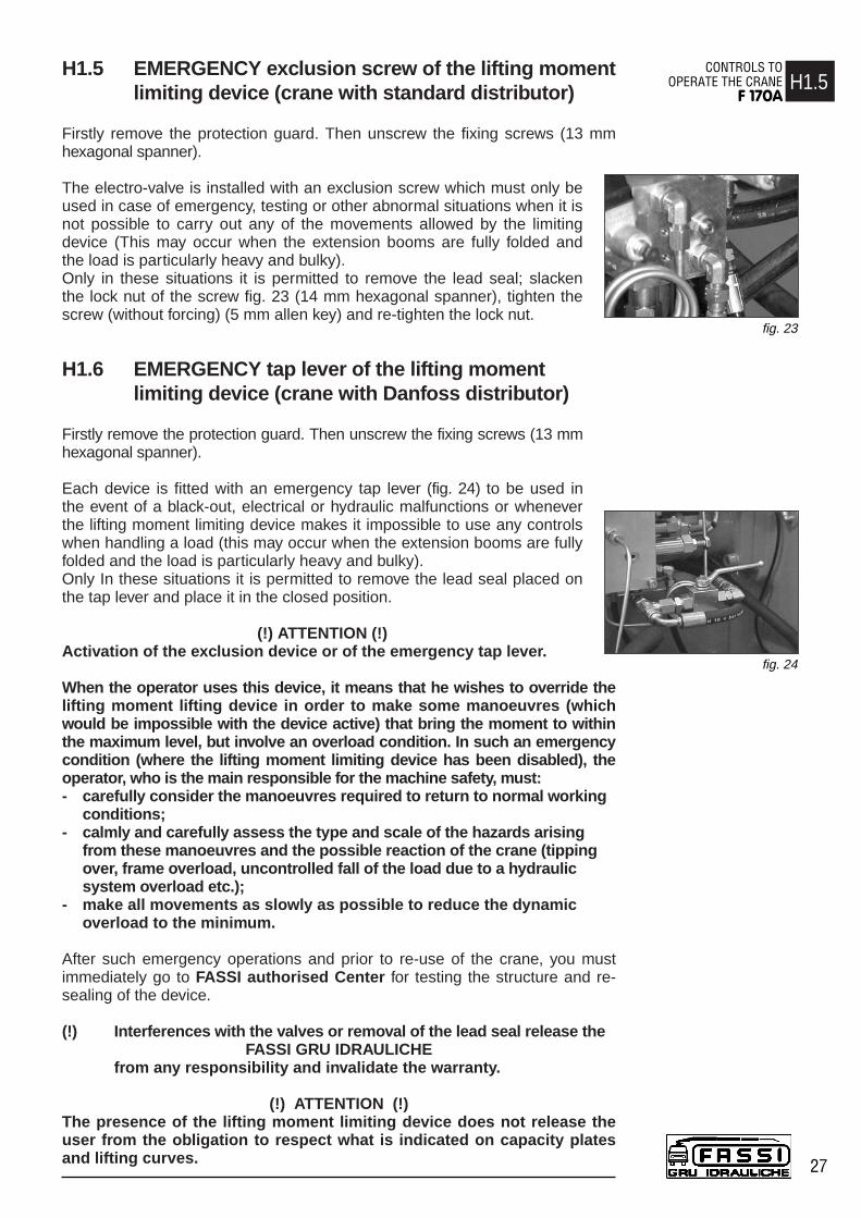
H1.5 EMERGENCY exclusion screw of the lifting moment limiting device (crane with standard distributor)
Firstly remove the protection guard. Then unscrew the fixing screws (13 mmhexagonal spanner).
The electro-valve is installed with an exclusion screw which must only beused in case of emergency, testing or other abnormal situations when it isnot possible to carry out any of the movements allowed by the limitingdevice (This may occur when the extension booms are fully folded andthe load is particularly heavy and bulky). Only in these situations it is permitted to remove the lead seal; slackenthe lock nut of the screw fig. 23 (14 mm hexagonal spanner), tighten thescrew (without forcing) (5 mm allen key) and re-tighten the lock nut.
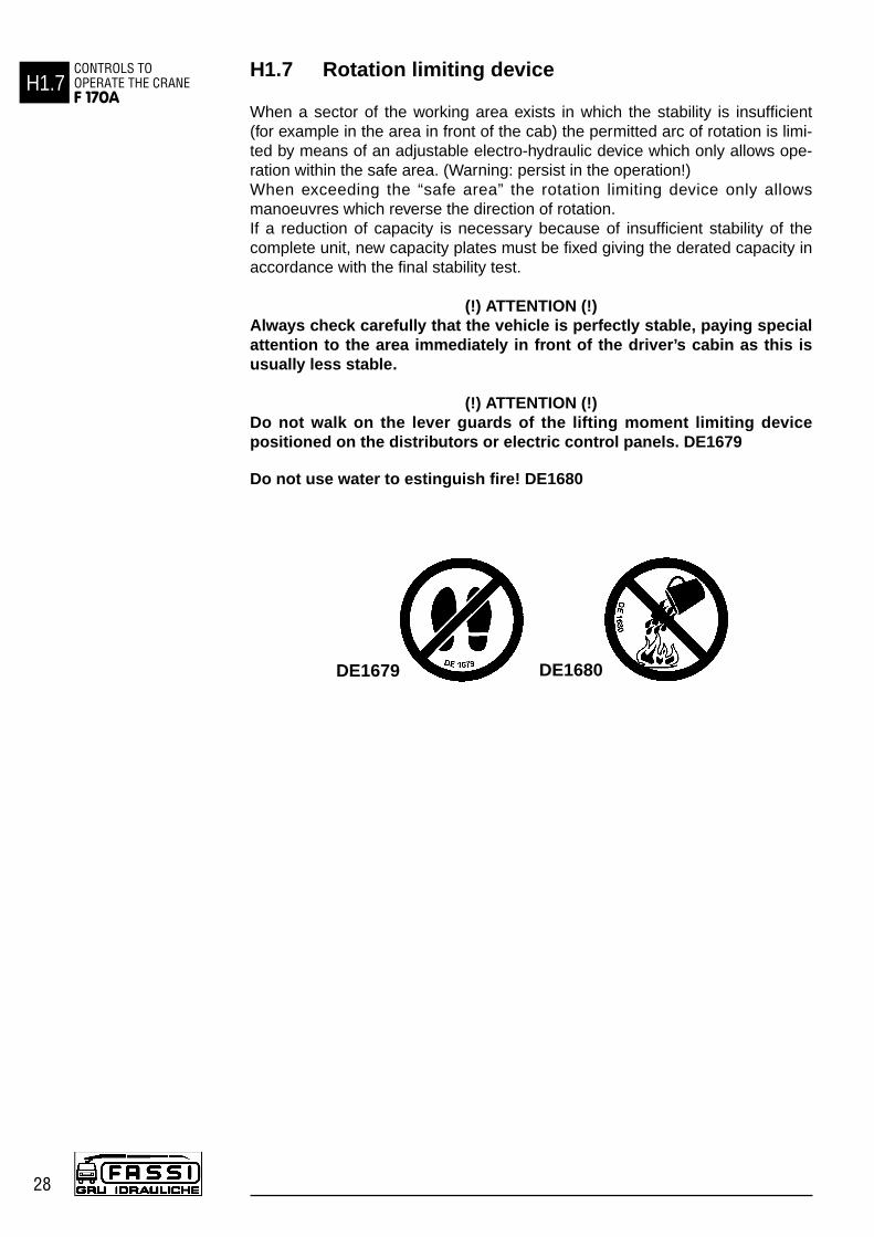
H1.6 EMERGENCY tap lever of the lifting moment limiting device (crane with Danfoss distributor)
Firstly remove the protection guard. Then unscrew the fixing screws (13 mmhexagonal spanner).
Each device is fitted with an emergency tap lever (fig. 24) to be used inthe event of a black-out, electrical or hydraulic malfunctions or wheneverthe lifting moment limiting device makes it impossible to use any controlswhen handling a load (this may occur when the extension booms are fullyfolded and the load is particularly heavy and bulky).Only In these situations it is permitted to remove the lead seal placed onthe tap lever and place it in the closed position.
(!) ATTENTION (!)Activation of the exclusion device or of the emergency tap lever.
When the operator uses this device, it means that he wishes to override thelifting moment lifting device in order to make some manoeuvres (whichwould be impossible with the device active) that bring the moment to withinthe maximum level, but involve an overload condition. In such an emergencycondition (where the lifting moment limiting device has been disabled), theoperator, who is the main responsible for the machine safety, must:- carefully consider the manoeuvres required to return to normal working
conditions;- calmly and carefully assess the type and scale of the hazards arising
from these manoeuvres and the possible reaction of the crane (tippingover, frame overload, uncontrolled fall of the load due to a hydraulicsystem overload etc.);
- make all movements as slowly as possible to reduce the dynamicoverload to the minimum.
After such emergency operations and prior to re-use of the crane, you mustimmediately go to FASSI authorised Center for testing the structure and re-sealing of the device.
(!) Interferences with the valves or removal of the lead seal release theFASSI GRU IDRAULICHE
from any responsibility and invalidate the warranty.
(!) ATTENTION (!)The presence of the lifting moment limiting device does not release theuser from the obligation to respect what is indicated on capacity platesand lifting curves.
H1.5CONTROLS TO
OPERATE THE CRANEF 170A
27
fig. 23
fig. 24
H1.7 Rotation limiting device
When a sector of the working area exists in which the stability is insufficient(for example in the area in front of the cab) the permitted arc of rotation is limi-ted by means of an adjustable electro-hydraulic device which only allows ope-ration within the safe area. (Warning: persist in the operation!) When exceeding the “safe area” the rotation limiting device only allowsmanoeuvres which reverse the direction of rotation.If a reduction of capacity is necessary because of insufficient stability of thecomplete unit, new capacity plates must be fixed giving the derated capacity inaccordance with the final stability test.
(!) ATTENTION (!)Always check carefully that the vehicle is perfectly stable, paying specialattention to the area immediately in front of the driver’s cabin as this isusually less stable.
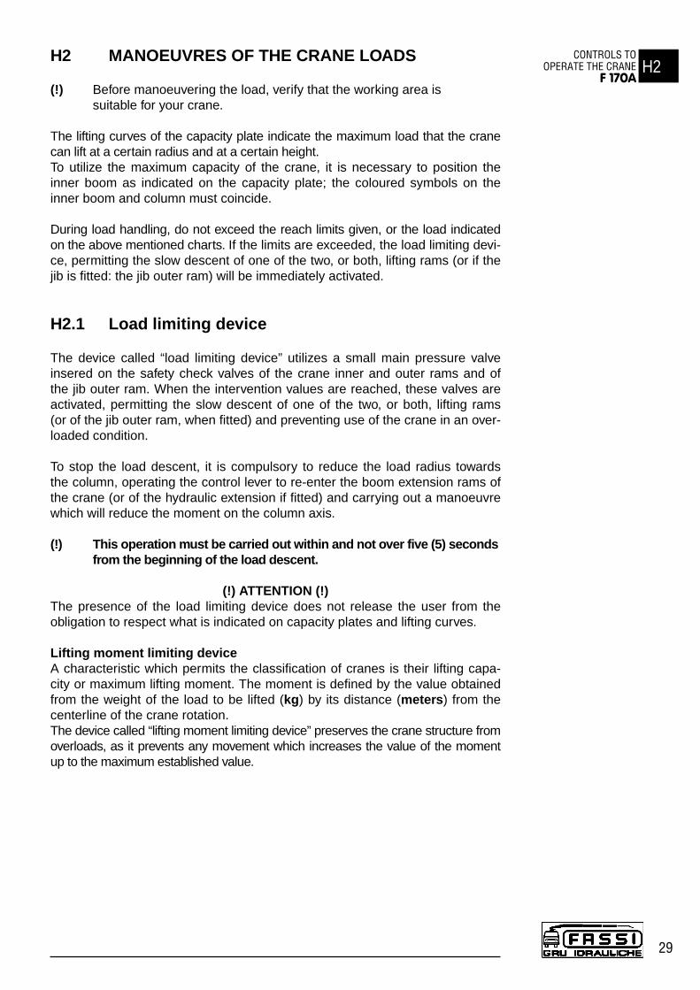
(!) ATTENTION (!)Do not walk on the lever guards of the lifting moment limiting devicepositioned on the distributors or electric control panels. DE1679
Do not use water to estinguish fire! DE1680
H1.7CONTROLS TO OPERATE THE CRANEF 170A
28
DE1679 DE1680
H2 MANOEUVRES OF THE CRANE LOADS
(!) Before manoeuvering the load, verify that the working area is suitable for your crane.
The lifting curves of the capacity plate indicate the maximum load that the cranecan lift at a certain radius and at a certain height.To utilize the maximum capacity of the crane, it is necessary to position theinner boom as indicated on the capacity plate; the coloured symbols on theinner boom and column must coincide.
During load handling, do not exceed the reach limits given, or the load indicatedon the above mentioned charts. If the limits are exceeded, the load limiting devi-ce, permitting the slow descent of one of the two, or both, lifting rams (or if thejib is fitted: the jib outer ram) will be immediately activated.
H2.1 Load limiting device
The device called “load limiting device” utilizes a small main pressure valveinsered on the safety check valves of the crane inner and outer rams and ofthe jib outer ram. When the intervention values are reached, these valves areactivated, permitting the slow descent of one of the two, or both, lifting rams(or of the jib outer ram, when fitted) and preventing use of the crane in an over-loaded condition.
To stop the load descent, it is compulsory to reduce the load radius towardsthe column, operating the control lever to re-enter the boom extension rams ofthe crane (or of the hydraulic extension if fitted) and carrying out a manoeuvrewhich will reduce the moment on the column axis.
(!) This operation must be carried out within and not over five (5) secondsfrom the beginning of the load descent.
(!) ATTENTION (!)The presence of the load limiting device does not release the user from theobligation to respect what is indicated on capacity plates and lifting curves.
Lifting moment limiting deviceA characteristic which permits the classification of cranes is their lifting capa-city or maximum lifting moment. The moment is defined by the value obtainedfrom the weight of the load to be lifted (kg) by its distance (meters) from thecenterline of the crane rotation.The device called “lifting moment limiting device” preserves the crane structure fromoverloads, as it prevents any movement which increases the value of the momentup to the maximum established value.
H2CONTROLS TO
OPERATE THE CRANEF 170A
29

H2.2 Lifting moment limiting device “INTELLIGENT TYPE” (optional)
This device utilises an electrohydraulic technology, preventing any movement whichcauses an increase in the pressure induced by the load in the inner and outer ramsof the crane (and of the hydraulic extension if fitted), up to the “critical values”. Thesevalues, which are non-exceedable, determine the intervention levels and provide the
data for setting the device.
The lifting moment limiting device concernes the following manoeuvres:- Inner boom descent; the inner boom lift is controlled
by the general main pressure valve of the distributor. - Outer boom lift and descent.- Extension of extension boom sections.- Winch rope lift (if fitted).- If hydraulic extension is fitted: extension outer boom
lift and descent.- Extension of the jib extension booms section.
Crane with standard distributorThe lifting moment limiting device is based on hydraulic controlswhich are activated when the intervention value is reached and blockthe movements of the relevant distributor levers in one or both direc-tions. Please remember that the device will return the lever of the ele-ment being used to neutral position. The condition of intervention isoperated by the position of the outer boom (or, if hydraulic extension
is fitted, the position of the extension outer boom), on which the electronic signalposition (mercury level switch) is read by a special electrovalve. This determinesthe controls of the locking or unlocking (resetting) of the controls concerned.
Crane with Danfoss distributor (available on request)The lifting moment limiting device system uses the specific functions of the distributorby utilising an electro-hydraulic technology, it does not allow you exceed the setvalue, by disactivating the controls (levers in neutral position) commanded by the limi-ting device. The condition of intervention is operated by the position of the outerboom (or, if hydraulic extension is fitted, the position of the extension outer boom), onwhich the electronic signal position (mercury level switch) is read by a special electro-valve. This determines controls which are locking or unlocking (resetting) of the con-trols concerned. When the moment is reduced, it resets automatically (the manoeu-
vres blocked by the device are released). N.B.: There is a delay of four (4) seconds after themoment reduction before the reset can occur in order to safeguard the stability of the device.
Fig. 18a-b-c illustrate the configurations of the crane (and of the eventual hydraulicextension) with the manoeuvres allowed and not allowed by the device, in connectionwith the horizontal position of the crane and extension outer booms.
(!) CAUTION DANGER (!)On the outer boom there is a mercury capsule (mercury level switch) duly protectedand provided with the following warning stickers.
Mercury is extremely toxic. In case of replacement and/or scrapping, disposeof or recycle the capsule containing mercury with maximum care, and in accor-dance with the national regulations in force.
H2.3 REACTIVATION button of crane functions withstandard distributor in the absence of the electricpower
Firstly remove the protection guard. Then unscrew the fixing screws(13 mm hexagonal spanner).
On the distributor it has been installed an electro-valve with a manuallocking function (fig. 21) which allows to reactivate all the crane func-tions in case of absence of the electric power. Only in these condi-tions it is permitted to remove the lead seal which protects the device.Push the button and turn it into the clockwise sense (fig. 22 pos. 1-2);
the button stays in stable and closed position.
(!) When the electric power is restablished, remember to put the button in itsoriginal position, turning it into the anti-clockwise sense. (fig. 22 pos. 3-4)
H2.3CONTROLS TO OPERATE THE CRANEF 170A
30
fig. 18a
fig. 18b
fig. 18c
fig. 22 fig. 21

H2.4 EMERGENCY exclusion screw of the lifting moment limiting device (crane with standard distributor)
Firstly remove the protection guard. Then unscrew the fixing screws (13 mm hexagonalspanner).
The electro-valve is installed with an exclusion screw which must only be used incase of emergency, testing or other abnormal situations when it is not possible tocarry out any of the movements allowed by the limiting device (This may occur whenthe extension booms are fully folded and the load is particularly heavy and bulky). Only in these situations it is permitted to remove the lead seal; slacken the lock nutof the screw fig. 23 (14 mm hexagonal spanner), tighten the screw (without forcing)(5 mm allen key) and re-tighten the lock nut.
H2.5 EMERGENCY tap lever of the lifting moment limiting device (crane with Danfoss distributor)
Firstly remove the protection guard. Then unscrew the fixing screws (13 mm hexago-nal spanner). Fig. 24
Each device is fitted with an emergency tap lever (fig. 24) to be used in the event ofa black-out, electrical or hydraulic malfunctions or whenever the lifting moment limi-ting device makes it impossible to use any controls when handling a load (this mayoccur when the extension booms are fully folded and the load is particularly heavyand bulky).Only In these situations it is permitted to remove the lead seal placed on the taplever and place it in the closed position.
(!) ATTENTION (!)Activation of the exclusion device or of the emergency tap lever.
When the operator uses this device, it means that he wishes to override the liftingmoment lifting device in order to make some manoeuvres (which would beimpossible with the device active) that bring the moment to within the maximumlevel, but involve an overload condition. In such an emergency condition (wherethe lifting moment limiting device has been disabled), the operator, who is themain responsible for the machine safety, must:- carefully consider the manoeuvres required to return to normal working
conditions;- calmly and carefully assess the type and scale of the hazards arising from these
manoeuvres and the possible reaction of the crane (tipping over, frame overload,uncontrolled fall of the load due to a hydraulic system overload etc.);
- make all movements as slowly as possible to reduce the dynamic overloadto the minimum.
After such emergency operations and prior to re-use of the crane, you must immediatelygo to FASSI authorised Center for testing the structure and re-sealing of the device.
(!) Interferences with the valves or removal of the lead seal release the FASSI GRU IDRAULICHE
from any responsibility and invalidate the warranty.
(!) ATTENTION (!)The presence of the lifting moment limiting device does not release the user fromthe obligation to respect what is indicated on capacity plates and lifting curves.
(!) ATTENTION (!)Always check carefully that the vehicle is perfectly stable, paying special attentionto the area immediately in front of the driver’s cabin is usually less stable.
(!) ATTENTION (!)Do not walk on the lever guards of the lifting moment limiting device positioned onthe distributors or electric control panels. DE1679
Do not use water to estinguish fire! DE1680
H2.5CONTROLS TO
OPERATE THE CRANEF 170A
31
fig. 23
DE1679
DE1680
fig. 24

L0 USE OF IMPLEMENTS
The crane, in load condition H1B3, can be provided with implements such as: - Manual extensions- Winches- Hydraulic extensions- Personnel baskets - Clam ‘shell buckets- Augers
(!) When using an implement it is always necessary to check that its weight,dimension and capacity is matched to the crane performances. For further information please refer to FASSI GRU IDRAULICHE
Warning and norms for crane use also apply for hydraulic implement use.
Before using a personnel basket it is necessary to provide the crane withthe safety devices requested by the local norms in force and prior to use ofthe crane it has to be tested and inspected in accordance with the local legalrequirements.
(!) In case of implements on the load or the truck body it is necessary to checkthey are locked to assure the impossibility of accidental movements.
(!) The crane can operate, intermit-tently and not continuously, with lifting devices other than the hook, only on loose and light materials (not on scrap iron).The dimensions and the capacity of the implements must be propor-tioned with crane performances.
(!) WARNING (!)CRUSHING OR PUSH MANOEUVRES ARE NOT PERMITTED.
L0.1 Hydraulic connections for implements - supple-mentary hoses.
(!) WARNING (!)To ensure that the control corresponds to the implement movement, hydraulicconnections are symmetrically fitted with coupling unions. Never invert suchpositions: movements inversion as well as operating difficulties or unusualoverload with implement itself could occur.
NOTEWhen using coupling unions it is necessary to verify that there is no trace of soil,curt etc. on the unions and inside the seats so as to avoid the oil contaminationand consequently wear the tightening “ surface of unions or ram seals.
L0USE OF IMPLEMENTSF 170A
32

L1 MANUAL EXTENSIONS
These are additional extensions, which are placed in the hydraulic extensionsof the crane and of the hydraulic jib and secured by locking pins.Manual extensions have a maximum capacity independent from the craneconfiguration as shown on the capacity plates.
(!) WARNING (!)Manual extensions are not protected by the lifting moment limiting device.
Before lifting the load make sure that its weight does not exceed the capacityindicated on the capacity plate.Manual extensions can be extracted from the rest position and be operative, oncethe security pins have been removed, with the outer boom in sliding position.
Verify that the area is suitable for this operation and there are no unauthorizedpersons in the working area.
Do not permit the extension to slide out at speed as this will damage thestroke end stops.
Do not try to align the holes (slots) for the locking pins with your fingers; alwaysuse a suitable tool.When manual extensions are in place, fit the locking pins and secure themwith the check pins to prevent accidental escape.
(!) Always remember that when operating with implements, their tare weightmust be deducted from the capacity of the crane.
L2 CONTROLS TO OPERATE THE HYDRAULICIMPLEMENTS OF THE CRANE
L1USE OF IMPLEMENTS
F 170A
33
The plates placed over each lever define their function in relation to theirmovement.
(!) ATTENTION (!)The sequence of the plates placed on the crane controls may be different.
Make sure that the lever you are going to operate correspond to the controlyou selected.
IMPLEMENTS CONTROLS1 Additional function
Winch Bucket
IMPLEMENTS CONTROLS2 Additional functions
Jib outer boom
Jib extension
booms
IMPLEMENTS CONTROLS2 Additional functions
Rotator Bucket
IMPLEMENTS CONTROLS3 Additional functions
Jib outer boom
Jib extension
booms
Winch

L3 WINCH
The winch is made of a drum that can rotate by means of a hydraulic motor, on astructure fixed on the crane. The rotation of the drum on which the cable winds isachieved by a hydraulic motor controlled by a safety check valve connected to thecrane circuit. A parking brake integrated to the motoreducer group hold the loadin position when the winch control lever is in neutral position.
Nomenclature of winch unit (fig. 25)
Pos. Description1. Winch2. Cable3. Fixed pulley4. Balance weight5. Hook 6. Transmission pulley7. Block (double-triple.... line)
(!) WARNING (!)Check the condition of wire rope.Do not rotate the crane before the load is lifted. Lift the load vertically using thecable and not the boom in order to avoid swinging the load. With the suspendedload rotate slowly and with care checking the stability of the vehicle.
L3.1 Winch for crane
The identification data and the essential characteristics are marked on a platefixed by the manufacturer and used for the CE mark which testifies its conformityto the Machine Directive (D.M.)
Manufacturer mark ...Winch type ...Serial number ...Maximum line in N at the 4th layer...Maximum speed in m/min ...
(!) See operator winch manual supplied by the winches’ manufacturer.
The winch has a maximum capacity, indicated by a plate, not related to thecrane capacities which can also be lower.
Consequently avoid to lift, with the winch, heavier loads than those allowedby the crane capacity plate.
The couple limiter, installed on the winch structure, prevents that on thecable, can be created a load major to the value of maximum line at the 4thlayer, quiescing all the crane controls.
(!) Under no circumstances interfere with the limiter device adjustment.
Winches are equipped with an end stroke device that in the lifting or in the boomsextension rams exit prevents the cable hook or the block from hitting the fixed pul-ley, and in the unwinding keeps at least three (3) turns of the cable wound aroundthe winch drum, tripping either device disactivates the relevant controls.
To reactivate the controls the winch control lever must be activated controlling:- the descent if the device operation is happened in the lifting or in exit with
the booms extension rams;- the lifting if the operation is happened in the unwinding of the same one.
L3USE OF IMPLEMENTSF 170A
34
fig. 25

It is recommended to avoid working with the cable hook or the block tooclose to the pulley structure; the activation of the device could provoquedangerous swinging.
The pulley structure is provided with a group with microswitch (fig. 27) whoselever is kept in position by a balance weight (sliding on the cable); the cablehook or the block lift the balance weight thus releasing the lever becomesimpossible with the consequent disactivation of the controls. Please note thateach movement of the crane resulting in the exclusion of the balance weightaction, engenders the disactivation of the controls.
Folding the crane in rest position- withdraw the flying drive (it is assembled on the cable of the cable winder)
from the pin placed near the microswitch, placed on the pulley, assembledon the booms extension rams.
- Release the cable from all support rings placed on the booms letting thatit winds free in the cable winder.
- Insert the flying drive in the pin placed in the cable winder; this operationgets active all crane controls to complete the rest position operations.
- Withdraw the cable from the pulleys, then remove them from the crane(reposition the pins and the security pins)
- Operate the ascent of the winch in order to wind the cable on winch drum, alwayskeeping the cable in tension; with the cable layer easing the regular rewinding andwithout overlaps.
- Hook the thimble to a support apt to keep the cable sufficiently taut.
NOTEOn cranes fitted with hydraulic extension, in some cases the winch is mounted ona rotating support to reduce the overall dimensions; to put the winch to the restposition, operate as following:- to position the outer boom vertically.- to withdraw the security pin, the screw nut and the locking pin from the supports.
The pin should be withdraw easily and without putting up resistance; if so thewinch support is not enough vertical with consequent dangerous rotation ofthe group when the pin is finally removed. Then position the crane outer boomin vertical position, and try to withdraw the security pin once again.
- Rotate the winch support until it reaches its new position, - Insert the locking pin, the screw nut and the security pin.
To put the crane in working position it is necessary to carry out the operationsin reverse.
Rotate the winch support with extreme care in order not to damage the hosesand electric components.
To fold the crane in rest position see Paragraph H0.2
(!) ATTENTION (!)Please remember that after placing the crane in working position it iscompulsory to reset the functionality of end stroke device, otherwise thecable could be damaged.
L3.2 Winch for crane
(!) ATTENTION (!)It is necessary to avoid, on pain of damaging the cable, that:- in the lifting with the winch or in the booms extension rams exit the
cable hook (or the block) takes contact with the fixed pulley;- in the unwinding the cable is completely wound from the winch drum;
three -3- turns must be wound at least, causing the controls quiescing.
(!) On winches not equipped with cable layer, check the rewinding of thecable on winch drum proceeds regularly and without overlapping: it issuggested to rewind the cable only if it is sufficiently taut.
L3.1USE OF IMPLEMENTS
F 170A
35
fig. 27

L4 HYDRAULIC JIBS
The hydraulic jibs, foldable behind the cab, are additional booms, with articulationand with one or more extension booms to be fitted to the last extension boom ofthe crane; on request the manual extensions can be installed on the extensionbooms of the jib.
Hydraulic jibsExtension type Weight=kg Manual Weight=kg Manual Weight=kg Manual Weight=kg
L102 320 ML10 20 ------------------------ ------------------------L202 515 ML20 38 NL20 30 PL20 20L203 595 ------------------------ NL20 30 PL20 20L313 750 NL31 48 PL31 29 QL31 23L314 850 ------------------------ PL31 29 QL31 23
NOTE The weights reported in the table are indicative and can vary in relation to thefittings.
The jibs are fitted by means of the insertion of the extension connecting boominto the crane extension boom; the fixing to the crane is obtained through lockingpins. The hydraulic connection to the supplementary functions of the crane, isthrough quick couplings.
(!) Warnings and norms for crane utilisation apply also for hydraulic jibs use.
(!) Warnings and norms for manual extensions are indicated at Paragraph L1.
(!) ATTENTION (!)It is recommended to employ lifting means adequate to the weight of the load andradius of the extensions; during this operation the operator is responsible for themachine safety.The slings or the cables used for handling the load should have the adequatecapacity and length; try to avoid the load overturning by having one length pas-sed through itself and the other one through the hook.
L4.1 Identification of the hydraulic jib
The model, the version of the crane, the year of construction and the serialnumber are stamped on the hydraulic jib (fig. 28) in the following sequence:
L102*03*001 A = modelB = year of construction
A B C C = serial number
L4.2 Nomenclature of the hydraulic jib
Pos. Description
1. Connecting boom2. Locking pins3. Jib outer ram4. Jib outer boom5. Boom extension rams6. Extension booms7. Manual extension (on request)
L4USE OF IMPLEMENTSF 170A
36
fig. 28
Punching
8. Lifting hookL4.3 Manoeuvres to unfold the jib in working condition
Operate as described to put the crane in working condition (paragraph H0.1).
By operating the corresponding levers: - open the outer boom of the jib;- extend the jib outer boom sliding sections;- position the hook on the centerline of the load.
L4.4 Manoeuvres to fold the jib in rest condition
By operating the corresponding levers:- re-enter the hydraulic sections of the jib and of the crane;- lift the inner boom to its stroke end;- re-enter the outer boom of the jib and of the crane to its stroke end;- operate, as described, to fold the crane in rest position.
L4.5 Operations to remove the hydraulic jib from the crane
By operating the corresponding levers:- re-enter the jib outer booms sliding sections to their stroke end;- extend the crane outer ram to its stroke end;- extend (of at least 1 - 1,5 m) the crane outer booms sliding sections;- re-enter the outer ram of the jib and the inner ram of the crane to obtain
the two rest brackets of the jib, either lay on the ground, or on the truckbody or, if possible, on a specific rest trestle;
- remove screwing the locking pins;- re-enter the outer booms sliding sections of the crane to free the first
boom of the crane jib;- disconnect the jib from the hydraulic circuit of the crane operating on the
quick couplings.
(!) Assure that the hydraulic jib is adequately stripped to avoid side turnover.
L4.6 Operations to mount the hydraulic jib on the crane
By operating the corresponding levers:- place the extension on the vehicle or on the ground in the direction of the
movement of the extension booms;- extend the crane outer ram to its stroke end and position the extension
booms of the crane not too close to the first boom of the jib in order to allowthe lining-up manoeuvres and the connection of the hoses;
- connect the jib hoses to the hydraulic plant through coupling unions, followingindications of Paragraph L0.1, Hydraulic connections for implements - supple-mentary hoses;
- operate the outer ram of the jib and the inner ram of the crane in order to alignthe extension booms of the crane and the first boom of the jib thus allowing theirconnection;
- eventually repeat the previous operation until the fixing holes are aligned,working on the extension booms of the crane;
- insert the lock pin into the fixing holes and secure it with the check pin.
L4.3USE OF IMPLEMENTS
F 170A
37

M0 MAINTENANCE INSTRUCTIONS
To assure a long life to the crane, it is necessary to meticulously follow themaintenance instructions.
General lubrication and small repairs can be carried out by the user; repairs of amore complicated nature must be carried out by authorized service personnel.
Spare parts must be original.
Good maintenance and proper use are imperative to maintain efficient use andguarantee the safety of the crane.
At least once a year you must take the crane to a Fassi Service Center for acheck.
(!) Before disconnecting any hydraulic hoses, ensure that there is no pressure inthe hydraulic circuit. After removing hoses always mark them and their respective ports on thecrane. Faulty replacement can cause damage to the rams and to the hydrauliccircuit.
Respect the information supplied for maintenance and technical assistance.
Any maintenance operation must be carried out with the crane power sourceturned off. (in case of fixed mounting with hydraulic power pack, the electricmotor has to be turned off).
Do not place limbs, fingers or any other parts of anatomy into areas of thecrane, which present possibilities of shearing, without having blocked suchparts of the crane.
Do not weld, drill or grind any part of the crane without the Manufacturer’sauthorisation.
Do not weld thefixing rods of thecrane (see plateDE1574 fig. 29)
When repairs to,or checks of, thehydraulic circuitand of the ramsare carried out, it is very important not to use, or be in the proximity of, mate-rials which can damage the circuit or contaminate the hydraulic oil eg. metalshavings, sand or dust.
Do not use the high pressure washing on the controls (deviators, distributors,double controls, hand cable controls...), on the electronic components (boxes,control panels...), on the tanks.
Never use detergents, petrolsol or inflammable liquids, always use non flam-mable or non toxic liquids.
To avoid down time, it is recommended to periodically carry out the followingchecks.
M0MAINTENANCEINSTRUCTIONSF 170A
38
TIRANTI: NON SALDARE!
FIXING ROD: DO NOT WELD!
TIRANTS: NE PAS SOUDER!
ZUGSCHRAUBEN: NICHT SCHWEISSENDE1574
fig. 29

M0.1 At the end of every working day
- Check that all safety devices are efficient.- Check the level of the hydraulic oil in the tank.- Check all the components of the hydraulic circuit for possible leaks.- Check that the control and the oil diverter levers can easily be positioned;
they must show no signs of forcing.- Check the condition of shackles, hooks, wire ropes and any other lifting
equipment.
M0.2 After the first 40 hours use
Check the tightening torque of the fixing rods of thecrane (fig. 30).
See table at paragraph M0.4
M0.3 After every working week
Clean the oil filter placed in the oil tank of the crane andif any, on the pump section and pressure hoses.
NOTE The filters of fibre or paper can not be cleaned, they must be replaced.
Cleaning of the wire mesh filter on the tank (oil return tothe oil-tank) fig. 31.
- Unscrew the security bolts of the filter cover 1 and remove it.
- Extract the cartridge, clean by flushing with a non flammable, non corrosive and non toxic solvent (gas oil or other). Thoroughly dry the filter inside and out (do not use compressed air).
- Check if the cartridge has collapsed; if so, replace it!- Remove the filter body 3 and clean it.- Re-assemble the filter body and the cartridge: check the
sealing of the ‘O’ ring 4-5-6; in case, replace it!
NOTETake care that no contaminated material passes into the tank.
Replacement of the filter on the delivery line (before the distri-butor) fig. 32.- When the visual indicator becomes red, replace the cartridge.- Unscrew with a suitable spanner the filter body (1) from
the head (2).- Remove the cartridge (3) and replace it!- Clean inside the holder.- Re-assemble checking the seal (4) on the filter body.- Screw the filter body into the head.
Check the oil level in the tank with the crane in the foldedposition and with the outriggers (crane and supplemen-tary) fully re-entered. The oil level must not exceed themaximum or be lower than the minimum (fig. 33).
Top up using hydraulic oil with the same characteristics as those indicated in thetable at paragraph N0.
M0.1MAINTENANCEINSTRUCTIONS
F 170A
39
fig. 30
fig. 31
fig. 32
MAXMIN
fig. 33

The following lubricators have been centralizedand gathered in a case (fig. 34) positioned onthe base (crane distributor side):- rack guide shoe - rotation,- upper and lower bush of the column - column
support, - rack group - column gear,- column support group - pendulum beam.
(!) WARNING (!)At low temperatures, the grease shall not crystallize or, to be more precise, shallnot change its characteristics. At the effective operative temperature, the greasewe recommend shall have a fluidity at least equal to rating NLGI 0 or max. 1
(!) WARNING (!)Centralized lubrication shall not be used when room temperature isbelow -10°C / -20°C.
All the lubricators mounted on the crane are protected by a plastic cap so toavoid the oil contamination.
Periodically grease the points indicated on the crane (fig. 35) (and on thehydraulic jib, when fitted, fig. 36) paying particular attention to the points noteasily detected.
For the sliding sections of the outrigger supports and of the extension boomsguide shoes made from a special material have been fitted: to ease their move-ment it is recommended to smear a light film of grease on them, taking care thatthe surfaces of the extension booms are free from impurities such as sand etc.
Use a grease with the same characteristics indicated in the table at Paragraph N0.
M0.3MAINTENANCEINSTRUCTIONSF 170A
40
fig. 34
fig. 36
fig. 35

M0.4 After every 500 working hours
Check the tightening torque:- of the fixing rods of the crane; consult the following table in order to find it’s
value according to the bolt diameter:
Table of the tightening torques of the fixing rods of the crane on the vehicleFrom “C0404 Kit for crane fixing”.
D. Fixing Tighteningrods torque = Nm
M22x1,5 300M24x2,0 400M27x2,0 600M30x2,0 471M33x2,0 1200M39x3,0 1800
- of the securing bolts for the ram pins and of all the other bolts and screws,where the tightening torque is not expressly indicated, consult the followingtable in order to find it’s value according to the bolt diameter and class.
Table of the bolts tightening torque with average friction value (0,15) and average-good tightening accuracy (C).
From ... “ELEMENTS DE FIXATION - ASSEMBLAGES VISSES” (AFNOR E 25-030 1984)
Diameter Class 8.8 Class 10.9 Class 12.9Bolt = D Torque = Nm Torque = Nm Torque = Nm
3 1,06 1,56 1,834 2,44 3,58 4,195 4,83 7,10 8,306 8,30 12,30 14,308 20 29 3510 40 59 6912 69 102 11914 111 163 19116 173 255 29818 239 352 41220 339 499 58422 466 685 80224 584 858 100427 865 1271 148730 1173 1723 201633 1594 2342 274036 2046 3006 351739 2658 3905 4570
Check the guide shoe wear as it affects the sliding section tolerances; if theclearances are considerable, damage to the rams and the structure may occur.
Clean the air filter placed in the top of the oil tank filter cap.
Completely replace the hydraulic oil and the filter cartridges.
(!) The waste oil and the filter cartridges MUST be disposed of byauthorized persons.
M0.4MAINTENANCEINSTRUCTIONS
F 170A
41

(!) ATTENZIONE PERICOLO (!)
Sul braccio secondario è installata una bolla a mercurio (interruttore di livelloa mercurio) opportunamente incapsulata e protetta e munita di etichetta ade-siva d’avvertimento.
IN CASO DI SOSTITUZIONE E/O ROTTAMAZIONE LA CAPSULA CONTE-NENTE MERCURIO VA RICICLATA CON ESTREMA ATTENZIONE ECOMUNQUE SECONDO LE NORME NAZIONALI VIGENTI IN QUANTO ILMERCURIO È MATERIALE ALTAMENTE TOSSICO.
M0.5 Revisione completa della gru
Al raggiungimento di uno dei limiti indicati sotto deve essere eseguita unarevisione generale con approfondita verifica strutturale della macchinastessa a cura della ditta costruttrice o di una sua officina autorizzata.
10.000 ore di lavoro
(es.: 10 anni, 50 settimane all’anno, 20 ore alla settimana, oppure 5 anni, 50 settimane all’anno, 40 ore alla settimana)
10 anni di vita della gru
M0.4MAINTENANCEINSTRUCTIONSF 170A
42

N0
43
TABLE OF HYDRAULIC OIL AND LUBRICANTS
CHARACTERISTICSF 170A
N0 TABLE OF HYDRAULIC OIL AND LUBRICANTSCHARACTERISTICS
HYDRAULIC OIL WITH HIGH VISCOSITY: ISO-L-HV
Minimal external maximal oil Gradationtemperature: temperature:
-35°C +45°C ISO VG 32-20°C +75°C ISO VG 46
HYDRAULIC OIL WEAR RESISTANT: ISO-L-HM
Minimal external maximal oil Gradationtemperature: temperature:
-10°C +60°C ISO VG 32+ 0°C +75°C ISO VG 46+ 5°C +85°C ISO VG 68+10°C +90°C ISO VG 100
GREASE
Consistency: NLGI BEACON EP 2 - BEACON 3
LUBRICATING OIL (for winch cable)
The most suitable here is a general-purpose lubricating oil with about SAE30° viscosity. A lubricating oil containing non-stick additives is recommendedif the cables are expected to move quickly through the pulleys.
BRILUBE 50 (BRITISH ROPES - BRINDON)
( ! ) WARNING ( ! ) Don’t use greases with solid particles as “Bisulphide of Molybdenum”.

P0POSSIBLE FAULTSF 170A
44
P0 POSSIBLE FAULTS
Many years experience of our product has allowed us to identify and classifythe most common faults which occur. In most cases it requires accuratehydraulic and electric troubleshooting and simple rectification. In the followingtable we report the most frequent inconveniences and our suggested reme-dies.
(!) Checking and adjustment of oil pressures of valve settings must be carried out by an authorized service agent, under penalty of warranty forfeiture.
P0.1 Operations which can be carried out by the user
FAULTS CAUSE REMEDIES
The crane does not rotate Vehicle non Stabilize the vehicleproperly in level position
Lack of lubrication Grease the bushes andthe rotation guide shoe
The extension booms Lack of lubrication Greasedo not completely extend of the guide shoes the guide shoes
or work jerkily
Crane controls are Lack of Check the fuse,not active electric energy the battery and
electric circuit
Winch end stroke See L3.1active
The rotation limiting device See H1.7is activated
Vibrations in Shortage of oil Check the levelcrane operations and top up
if necessary
Obstructed filters Clean or replace the filter cartridge
Noteable decrease in Obstructed filters Clean or replacemovement speed the filter cartridge

P0.2POSSIBLE FAULTS
F 170A
45
P0.2 Operations to be carried out by an authorizedservice center.
FAULTS CAUSE REMEDIES
The crane does not lift Non efficiency Replace the pumpthe loads indicated of the pump
on the capacity plate(main pressure or auxiliary) Check the pressure,
valves not properly adjust the valvesadjusted, or worn or replace them!
Ram seals are Replace the sealsnot properly fitted
A boom of the crane The safety check valve Replace the valvedoes not hold up the load the ram is open
and visually lowers
Oil leaks inside the ram Defective seals,replace them!
The crane does not Valves controlling the Adjust the valvesrotate properly rotation not adjusted
Wear of rotation guide shoe Replace the guide shoe
Wear of the seals Replace the sealsof the rotation cylinder
The extension booms Wear of guide shoes Check the do not completely extend guide shoes wear,
or work jerkily replace if necessary
Vibrations in Non efficient pump Check the pumpcrane operations
Noteable decrease in Non efficient pump Check the pumpmovement speed

R0INSTRUCTION AND WARNING PLATESF 170A
46
DE 4236Instruction plate and safety norms
DE 2327Warning plate to stabilize the vehiclebefore using the crane
Warning plates to make sure that no one is or transits in close proximity of the outriggers
DE 2497 DE 2498
DE 1684ADo not operate from the double controlside, to unfold or fold the crane
R0 INSTRUCTION AND WARNING PLATES

R0INSTRUCTION AND WARNING PLATES
F 170A
47
DE 1574Do not weld the fixing rods
DE 1682 Greasing points at pressure
DE 1679Do not walk on...
DE 1686Do not walk or stop under a suspendedload
DE 1683Do not operate in proximity of electric high-tension lines
DE 2361Do not operate in proximity of electric high-tension lines
DE 1681 Greasing points with brush
DE 1680Do not use water to estinguish fire
TIRANTI: NON SALDARE!
FIXING ROD: DO NOT WELD!
TIRANTS: NE PAS SOUDER!
ZUGSCHRAUBEN: NICHT SCHWEISSEN!DE1574
DE2361

S0 HYDRAULIC SCHEMATICS FOR CRANE
Hydraulic schematic for crane - HCD4 distributor - ground controls - lifting momentlimiting device “intelligent type”
S0HYDRAULIC SCHEMATICS FOR CRANEF 170A
48
CODE DESCRIPTION
DV002 DEVIATORDV008 DEVIATOREV104 ELECTROVALVEEV117 ELECTROVALVEFI870 FILTERM1/M4 GAUGE QUICK CONNECTIONPR103 PRESSURE SWITCHRU975 FAUCETVA102 DOUBLE EFFECT BLOCK VALVE VA175 BLOCK VALVE + FAUCETVA177 ANTIBURST VALVE FOR LIFTING RAMSVA185 SELECTOR VALVE
VA187 BLOCK VALVE + FAUCETVA194 DOUBLE EFFECT BLOCK VALVE VA209 SIMPLE EFFECT BLOCK VALVEVA215 OIL FLOW CHECK VALVEVA217 SEQUENCE VALVEVA224 LIFTING MOMENT LIMITING DEVICE VALVEVA226 ELECTRIC MAIN WITH BY PASS VALVEVA227 SEQUENCE VALVEVA232 DOUBLE EFFECT BLOCK VALVE
XPVA235 ELECTRIC MAIN WITH BY PASS VALVEVA240 "XP" VALVE

S0HYDRAULIC SCHEMATICS
FOR CRANEF 170A
49
Hydraulic schematic for crane - HCD4 distributor - top seat controls - lifting momentlimiting device “intelligent type”
CODE DESCRIPTION
DV002 DEVIATORDV008 DEVIATOREV104 ELECTROVALVEEV117 ELECTROVALVE FI870 FILTERM1/M4 GAUGE QUICK CONNECTIONPR103 PRESSURE SWITCHRU975 FAUCETVA102 DOUBLE EFFECT BLOCK VALVE VA175 BLOCK VALVE + FAUCET VA177 ANTIBURST VALVE FOR LIFTING RAMSVA185 SELECTOR VALVE VA187 BLOCK VALVE + FAUCET
VA194 DOUBLE EFFECT BLOCK VALVE VA209 SIMPLE EFFECT BLOCK VALVEVA214 LIFTING MOMENT LIMITING DEVICE VALVE VA217 SEQUENCE VALVEVA222 OIL FLOW REGULATOR VALVE FOR ROTATION
CYLINDER VA226 ELECTRIC MAIN WITH BY PASS VALVE VA227 SEQUENCE VALVEVA232 DOUBLE EFFECT BLOCK VALVE
XP VA235 ELECTRIC MAIN WITH BY PASS VALVEVA240 "XP" VALVE

S0HYDRAULIC SCHEMATICS FOR CRANEF 170A
50
Hydraulic schematic for crane - Danfoss distributor - lifting moment limiting device“intelligent type”
CODE DESCRIPTION
DV002 DEVIATORDV008 DEVIATOREV109 ELECTROVALVEFI870 FILTERM1/M4 GAUGE QUICK CONNECTIONPR103 PRESSURE SWITCHRU971 FAUCETRU975 FAUCETVA102 DOUBLE EFFECT BLOCK VALVE VA175 BLOCK VALVE + FAUCETVA177 ANTIBURST VALVE FOR LIFTING RAMSVA184 SENSOR VALVEVA185 SELECTOR VALVEVA187 BLOCK VALVE + FAUCET
VA194 DOUBLE EFFECT BLOCK VALVE VA209 SIMPLE EFFECT BLOCK VALVEVA222 OIL FLOW REGULATOR VALVE FOR ROTATION
CYLINDER VA224 LIFTING MOMENT LIMITING DEVICE VALVEVA225 LEVEL SENSOR VALVEVA226 ELECTRIC MAIN WITH BY PASS VALVEVA227 SEQUENCE VALVEVA232 UNIDIRECTIONAL VALVEVA233 DOUBLE EFFECT BLOCK VALVE VA234 ELECTRIC MAIN WITH BY PASS VALVE
XPVA235 ELECTRIC MAIN WITH BY PASS VALVEVA240 "XP" VALVE

S0HYDRAULIC SCHEMATICS
FOR CRANEF 170A
51
Hydraulic schematic for crane - versions:1) n° 2 functions for stabilizers - 2) “C” version
CODE DESCRIPTION
DI341 DISTRIBUTORVA102 DOUBLE EFFECT BLOCK VALVEVA187 BLOCK VALVE + FAUCETVA227 SEQUENCE VALVE

S1HYDRAULIC SCHEMATICS FOR CRANEF 170A
52
S1 HYDRAULIC SCHEMATICS FOR CRANE
Hydraulic schematic for crane - HCD4 distributor - ground controls - load limiting device
CODE DESCRIPTION
DV002 DEVIATORDV008 DEVIATORFI870 FILTERRU975 FAUCETVA102 DOUBLE EFFECT BLOCK VALVE VA175 BLOCK VALVE + FAUCETVA187 BLOCK VALVE + FAUCETVA194 DOUBLE EFFECT BLOCK VALVEVA209 SIMPLE EFFECT BLOCK VALVEVA215 OIL FLOW CHECK VALVEVA227 SEQUENCE VALVEVA233 DOUBLE EFFECT BLOCK VALVE

S1HYDRAULIC SCHEMATICS
FOR CRANEF 170A
53
CODE DESCRIPTION
DV002 DEVIATORDV008 DEVIATORFI870 FILTERRU975 FAUCETVA102 DOUBLE EFFECT BLOCK VALVEVA175 BLOCK VALVE + FAUCETVA187 BLOCK VALVE + FAUCETVA194 DOUBLE EFFECT BLOCK VALVE VA209 SIMPLE EFFECT BLOCK VALVEVA222 OIL FLOW REGULATOR VALVE FOR ROTATIONCYLINDER VA227 SEQUENCE VALVE
VA233 DOUBLE EFFECT BLOCK VALVE
Hydraulic schematic for crane - HCD4 distributor - top seat controls - load limiting device

S1HYDRAULIC SCHEMATICS FOR CRANEF 170A
54
CODE DESCRIPTION
DV002 DEVIATORDV008 DEVIATORFI870 FILTERRU975 FAUCETVA102 DOUBLE EFFECT BLOCK VALVEVA175 BLOCK VALVE + FAUCETVA187 BLOCK VALVE + FAUCETVA194 DOUBLE EFFECT BLOCK VALVE VA209 SIMPLE EFFECT BLOCK VALVEVA222 OIL FLOW REGULATOR VALVE FOR ROTATION CYLINDERVA227 SEQUENCE VALVEVA233 DOUBLE EFFECT BLOCK VALVE
Hydraulic schematic for crane - Danfoss distributor - load limiting device

T0ELECTRIC SCHEMATICS
FOR CRANEF 170A
55
T0 ELECTRIC SCHEMATICS FOR CRANE
Electric schematic for crane - HCD4 distributor - free rotation
CODE DESCRIPTION
ALIM FEED MAIN CONTROL PANELAV ACOUSTIC ALARMD1 LAMP TEST DIODED2 LAMP TEST DIODED3 POLARITY PROTECTION DIODEEV1 EMERGENCY ELECTROVALVEEV2 ELECTROVALVE FOR CRANE LIFTING BLOCKEV3 ELECTROVALVE FOR CRANE DESCENTS BLOCKF1 PROTECTION FUSE 10 A.LB WHITE WARNING LIGHT FOR FEED TO PANELLG1 YELLOW WARNING LIGHT FOR MAIN CONTROL PANEL
90% LOAD REACHINGLG2 YELLOW WARNING LIGHT FOR DOUBLE CONTROL SATELLITE
90% LOAD REACHINGLG3 YELLOW WARNING LIGHT FOR ADDITIONAL SATELLITE
90% LOAD REACHINGLP ADDITIONAL FLASHINGLR1 RED WARNING LIGHT FOR MAIN CONTROL PANEL BLOCKLR2 RED WARNING LIGHT FOR DOUBLE CONTROL SATELLITE BLOCKLR3 RED WARNING LIGHT FOR ADDITIONAL SATELLITE BLOCKMS MERCURY SLOPE SENSOR ON OUTER BOOMP1 LOAD PRESSURE 90% DETECTORP2 BLOCK PRESSURE DETECTORPC1 ACOUSTIC WARNING BUTTON FOR MAIN CONTROL PANELPC2 ACOUSTIC WARNING BUTTON FOR DOUBLE CONTROL SATELLITEPC3 ACOUSTIC WARNING BUTTON FOR ADDITIONAL SATELLITEPE1 MAIN CONTROL PANEL STOP BUTTONPE2 DOUBLE CONTROL SATELLITE STOP BUTTONPE3 ADDITIONAL SATELLITE STOP BUTTONSAT2 DOUBLE CONTROL SIDE SATELLITE SAT3 ADDITIONAL SATELLITE
WINCHAR1 CRANE WINDINGAR2 EXTENSION WINDINGLCV WINCH LOAD LIMITING DEVICELV1 MICRO LEVER FOR CABLE WINDING REACTIVATIONLV2 MICRO LEVER FOR CABLE UNWINDING REACTIVATIONMV1 PULLEY MICRO WINCHMV2 DRUM MICRO WINCH

Electric schematic for crane - HCD4 distributor - limited rotationT0ELECTRIC SCHEMATICSFOR CRANEF 170A
56
CODE DESCRIPTION
ALIM FEED MAIN CONTROL PANELAV ACOUSTIC ALARMD1 LAMP TEST DIODED2 LAMP TEST DIODED3 POLARITY PROTECTION DIODEEV1 EMERGENCY ELECTROVALVEEV2 ELECTROVALVE FOR CRANE LIFTING BLOCKEV3 ELECTROVALVE FOR CRANE DESCENTS BLOCKF1 PROTECTION FUSE 10 A.IP1 CLOCKWISE ROTATION PROXIMITYIP2 ANTICLOCKWISE ROTATION PROXIMITYLB WHITE WARNING LIGHT FOR FEED TO PANELLG1 YELLOW WARNING LIGHT FOR MAIN CONTROL PANEL
90% LOAD REACHINGLG2 YELLOW WARNING LIGHT FOR DOUBLE CONTROL SATELLITE
90% LOAD REACHINGLG3 YELLOW WARNING LIGHT FOR ADDITIONAL SATELLITE
90% LOAD REACHINGLMR1 CLOCKWISE ROTATION MICRO REACTIVATIONLMR2 ANTICLOCKWISE ROTATION MICRO REACTIVATIONLP ADDITIONAL FLASHINGLR1 RED WARNING LIGHT FOR MAIN CONTROL PANEL BLOCKLR2 RED WARNING LIGHT FOR DOUBLE CONTROL SATELLITE BLOCKLR3 RED WARNING LIGHT FOR ADDITIONAL SATELLITE BLOCKMR1 CLOCKWISE ROTATION RELAYMR2 ANTICLOCKWISE ROTATION RELAYMS MERCURY SLOPE SENSOR ON OUTER BOOMP1 LOAD PRESSURE 90% DETECTORP2 BLOCK PRESSURE DETECTORPC1 ACOUSTIC WARNING BUTTON FOR MAIN CONTROL PANELPC2 ACOUSTIC WARNING BUTTON FOR DOUBLE CONTROL SATELLITEPC3 ACOUSTIC WARNING BUTTON FOR ADDITIONAL SATELLITEPE1 MAIN CONTROL PANEL STOP BUTTONPE2 DOUBLE CONTROL SATELLITE STOP BUTTONPE3 ADDITIONAL SATELLITE STOP BUTTONSAT2 DOUBLE CONTROL SIDE SATELLITE SAT3 ADDITIONAL SATELLITESDP SEAT PROXIMITY SHUNT BOX
WINCHAR1 CRANE WINDINGAR2 EXTENSION WINDINGLCV WINCH LOAD LIMITING DEVICELV1 MICRO LEVER FOR CABLE WINDING REACTIVATIONLV2 MICRO LEVER FOR CABLE UNWINDING REACTIVATIONMV1 PULLEY MICRO WINCHMV2 DRUM MICRO WINCH

T0ELECTRIC SCHEMATICS
FOR CRANEF 170A
57
Electric schematic for crane - HCD4 distributor - diversified rotation
CODE DESCRIPTION
ALIM FEED MAIN CONTROL PANELAV ACOUSTIC ALARMD1 LAMP TEST DIODED2 LAMP TEST DIODED3 POLARITY PROTECTION DIODEEV1 EMERGENCY ELECTROVALVEEV2 ELECTROVALVE FOR CRANE LIFTING BLOCKEV3 ELECTROVALVE FOR CRANE DESCENTS BLOCKEV6 ELECTROVALVE FOR CRANE LIFTING MOMENT LIMITING DEVICE
OF THE TWO WORKING ZONESEV7 ELECTROVALVE FOR LIMITING GENERAL PRESSIONF1 PROTECTION FUSE 10 A.IP1 CLOCKWISE ROTATION PROXIMITYIP2 ANTICLOCKWISE ROTATION PROXIMITYLB WHITE WARNING LIGHT FOR FEED TO PANELLG1 YELLOW WARNING LIGHT FOR MAIN CONTROL PANEL
90% LOAD REACHINGLG2 YELLOW WARNING LIGHT FOR DOUBLE CONTROL SATELLITE
90% LOAD REACHINGLG3 YELLOW WARNING LIGHT FOR ADDITIONAL SATELLITE
90% LOAD REACHINGLMR1 CLOCKWISE ROTATION MICRO REACTIVATIONLMR2 ANTICLOCKWISE ROTATION MICRO REACTIVATIONLP ADDITIONAL FLASHINGLR1 RED WARNING LIGHT FOR MAIN CONTROL PANEL BLOCKLR2 RED WARNING LIGHT FOR DOUBLE CONTROL SATELLITE BLOCKLR3 RED WARNING LIGHT FOR ADDITIONAL SATELLITE BLOCKMR1 CLOCKWISE ROTATION RELAYMR2 ANTICLOCKWISE ROTATION RELAYMS MERCURY SLOPE SENSOR ON OUTER BOOMP1 LOAD PRESSURE 90% DETECTORP2 BLOCK PRESSURE DETECTORP4 ROTATION CONTROL PRESSURE DETECTORPC1 ACOUSTIC WARNING BUTTON FOR MAIN CONTROL PANELPC2 ACOUSTIC WARNING BUTTON FOR DOUBLE CONTROL SATELLITEPC3 ACOUSTIC WARNING BUTTON FOR ADDITIONAL SATELLITEPE1 MAIN CONTROL PANEL STOP BUTTONPE2 DOUBLE CONTROL SATELLITE STOP BUTTONPE3 ADDITIONAL SATELLITE STOP BUTTONSAT2 DOUBLE CONTROL SIDE SATELLITE SAT3 ADDITIONAL SATELLITESDP SEAT PROXIMITY SHUNT BOX
WINCHAR1 CRANE WINDINGAR2 EXTENSION WINDINGLCV WINCH LOAD LIMITING DEVICELV1 MICRO LEVER FOR CABLE WINDING REACTIVATIONLV2 MICRO LEVER FOR CABLE UNWINDING REACTIVATIONMV1 PULLEY MICRO WINCHMV2 DRUM MICRO WINCH

T0ELECTRIC SCHEMATICSFOR CRANEF 170A
58
Electric schematic for crane - Danfoss distributor - free rotation
CODE DESCRIPTION
ALIM FEED MAIN CONTROL PANELAV ACOUSTIC ALARMC1 BLOCK DELAY CONDENSORD3 POLARITY PROTECTION DIODED4/D5 LIFTING MOMENT LIMITING DEVICE DIODESD6/D7 LAMPS TEST DIODESD8/D9 DIODES OR NON RETURN DIODESEV2 ELECTROVALVE FOR CRANE LIFTING BLOCKEV3 ELECTROVALVE FOR CRANE DESCENTS BLOCKEV6 EMERGENCY ELECTROVALVEF1 PROTECTION FUSE 10AIPB PROXIMITY SENSOR VALVELB WHITE WARNING LIGHT FOR FEED TO PANELLG1 YELLOW WARNING LIGHT FOR MAIN CONTROL PANEL 90%
LOAD REACHINGLG2 YELLOW WARNING LIGHT FOR DOUBLE CONTROL SATELLITE
90% LOAD REACHINGLP ADDITIONAL FLASHINGLR1 RED WARNING LIGHT FOR MAIN CONTROL PANEL BLOCKLR2 RED WARNING LIGHT FOR DOUBLE CONTROL SATELLITE BLOCK MR3 RELAY FOR BLOCK DELAYMS MERCURY SLOPE SENSOR ON OUTER BOOMP1 90% LOAD PRESSURE DETECTORPC1 ACOUSTIC WARNING BUTTON FOR MAIN CONTROL PANELPC2 ACOUSTIC WARNING BUTTON FOR DOUBLE CONTROL SATELLITEPE1 MAIN CONTROL PANEL STOP BUTTONPE2 DOUBLE CONTROL SATELLITE STOP BUTTONRB LMLD BLOCK SIGNAL RELAYSAT. EC ELECTRIC CONTROL SATELLITE CABLESAT. RADIO REMOTE CONTROL SATELLITE CABLESAT2 DOUBLE CONTROL SIDE SATELLITE
SEQUENCEEV10 SEQUENCE ELECTROVALVEMSE SEQUENCE MICRO SWITCHSE SEQUENCE SHUNT BOX
WINCHAR1 CRANE WINDINGAR2 EXTENSION WINDINGEV11 MAIN LIFTING BLOCK ELECTROVALVEEV9 WINCH DESCENT BLOCK ELECTROVALVELCV WINCH LOAD LIMITING DEVICEMR4 WINCH RELAYMV1 PULLEY MICRO WINCHMV2 DRUM MICRO WINCH

T0ELECTRIC SCHEMATICS
FOR CRANEF 170A
59
Electric schematic for crane - Danfoss distributor - limited rotation
CODE DESCRIPTION
ALIM FEED MAIN CONTROL PANELAV ACOUSTIC ALARMC1 BLOCK DELAY CONDENSORD1/D2 ROTATION CONSENT DIODESD3 POLARITY PROTECTION DIODED4/D5 LIFTING MOMENT LIMITING DEVICE DIODESD6/D7 LAMPS TEST DIODESD8/D9 DIODES OF NON RETURN DIODESEV2 ELECTROVALVE FOR CRANE LIFTING BLOCKEV3 ELECTROVALVE FOR CRANE DESCENTS BLOCKEV6 EMERGENCY ELECTROVALVEEV7 CLOCKWISE ROTATION BLOCK ELECTROVALVEEV8 ANTICLOCKWISE ROTATION BLOCK ELECTROVALVEF1 PROTECTION FUSE 10AIP1 CLOCKWISE ROTATION PROXIMITYIP2 ANTICLOCKWISE ROTATION PROXIMITYIPB PROXIMITY SENSOR VALVELB WHITE WARNING LIGHT FOR FEED TO PANELLG1 YELLOW WARNING LIGHT FOR MAIN CONTROL PANEL 90%
LOAD REACHINGLG2 YELLOW WARNING LIGHT FOR DOUBLE CONTROL SATELLITE
90% LOAD REACHINGLP ADDITIONAL FLASHINGLR1 RED WARNING LIGHT FOR MAIN CONTROL PANEL BLOCKLR2 RED WARNING LIGHT FOR DOUBLE CONTROL SATELLITE BLOCK MR1 CLOCKWISE ROTATION RELAYMR2 ANTICLOCKWISE ROTATION RELAYMR3 RELAY FOR BLOCK DELAYMS MERCURY SLOPE SENSOR ON OUTER BOOMP1 90% LOAD PRESSURE DETECTORPC1 ACOUSTIC WARNING BUTTON FOR MAIN CONTROL PANELPC2 ACOUSTIC WARNING BUTTON FOR DOUBLE CONTROL SATELLITEPE1 MAIN CONTROL PANEL STOP BUTTONPE2 DOUBLE CONTROL SATELLITE STOP BUTTONRB LMLD BLOCK SIGNAL RELAYSAT. EC ELECTRIC CONTROL SATELLITE CABLESAT. RADIO REMOTE CONTROL SATELLITE CABLESAT2 DOUBLE CONTROL SIDE SATELLITESDP SEAT PROXIMITY SHUNT BOX
SEQUENCEEV10 SEQUENCE ELECTROVALVEMSE SEQUENCE MICRO SWITCHSE SEQUENCE SHUNT BOX
WINCHAR1 CRANE WINDINGAR2 EXTENSION WINDINGEV11 MAIN LIFTING BLOCK ELECTROVALVEEV9 WINCH DESCENT BLOCK ELECTROVALVELCV WINCH LOAD LIMITING DEVICEMR4 WINCH RELAYMV1 PULLEY MICRO WINCHMV2 DRUM MICRO WINCH

T0ELECTRIC SCHEMATICSFOR CRANEF 170A
60
Electric schematic for crane - Danfoss distributor - diversified rotation
CODE DESCRIPTION
ALIM FEED MAIN CONTROL PANELAV ACOUSTIC ALARMC1 BLOCK DELAY CONDENSORD1/D2 ROTATION CONSENT DIODESD3 POLARITY PROTECTION DIODED4/D5 LIFTING MOMENT LIMITING DEVICE DIODESD6/D7 LAMPS TEST DIODESD8/D9 DIODES OF NON RETURN DIODESEV1 ELECTROVALVE FOR CRANE (EMERGENCY STOP) DUMP-VALVEEV2 ELECTROVALVE FOR CRANE LIFTING BLOCKEV3 ELECTROVALVE FOR CRANE DESCENTS BLOCKEV4 ELECTROVALVE FOR CRANE LIFTING MOMENT LIMITING
DEVICE FOR TWO WORKING ZONES EV6 EMERGENCY ELECTROVALVEEV7 CLOCKWISE ROTATION BLOCK ELECTROVALVEEV8 ANTICLOCKWISE ROTATION BLOCK ELECTROVALVEF1 PROTECTION FUSE 10AIP1 CLOCKWISE ROTATION PROXIMITYIP2 ANTICLOCKWISE ROTATION PROXIMITYIPB PROXIMITY SENSOR VALVELB WHITE WARNING LIGHT FOR FEED TO PANELLG1 YELLOW WARNING LIGHT FOR MAIN CONTROL PANEL 90%
LOAD REACHINGLG2 YELLOW WARNING LIGHT FOR DOUBLE CONTROL SATELLITE
90% LOAD REACHINGLP ADDITIONAL FLASHINGLR1 RED WARNING LIGHT FOR MAIN CONTROL PANEL BLOCKLR2 RED WARNING LIGHT FOR DOUBLE CONTROL SATELLITE BLOCK MR1 CLOCKWISE ROTATION RELAYMR2 ANTICLOCKWISE ROTATION RELAYMR3 RELAY FOR BLOCK DELAYMS MERCURY SLOPE SENSOR ON OUTER BOOMP1 90% LOAD PRESSURE DETECTORP3 PRESSURE SWITCH CONTROLLING DOUBLE LMLD ZONEPC1 ACOUSTIC WARNING BUTTON FOR MAIN CONTROL PANELPC2 ACOUSTIC WARNING BUTTON FOR DOUBLE CONTROL SATELLITEPE1 MAIN CONTROL PANEL STOP BUTTONPE2 DOUBLE CONTROL SATELLITE STOP BUTTONRB LMLD BLOCK SIGNAL RELAYSAT. EC ELECTRIC CONTROL SATELLITE CABLESAT. RADIO REMOTE CONTROL SATELLITE CABLESAT2 DOUBLE CONTROL SIDE SATELLITESDP SEAT PROXIMITY SHUNT BOX
SEQUENCEEV10 SEQUENCE ELECTROVALVEMSE SEQUENCE MICRO SWITCHSE SEQUENCE SHUNT BOX
WINCHAR1 CRANE WINDINGAR2 EXTENSION WINDINGEV11 MAIN LIFTING BLOCK ELECTROVALVEEV9 WINCH DESCENT BLOCK ELECTROVALVELCV WINCH LOAD LIMITING DEVICEMR4 WINCH RELAYMV1 PULLEY MICRO WINCHMV2 DRUM MICRO WINCH

T0ELECTRIC SCHEMATICS
FOR CRANEF 170A
61
Electric schematic for crane - main control panel - HCD4 distributor
Electric schematic for crane - satellite for 2°-3° control station - HCD4 distributor

T0ELECTRIC SCHEMATICSFOR CRANEF 170A
62
Electric schematic for crane - main control panel - Danfoss distributor
Electric schematic for crane - satellite for 2°-3° control station - Danfoss distributor

T1ELECTRIC SCHEMATICS
FOR CRANEF 170A
63
CODE DESCRIPTION
ALIM FEED MAIN CONTROL PANELC1 BLOCK DELAY CONDENSORD3 POLARITY PROTECTION DIODEEV2 ELECTROVALVE FOR CRANE LIFTING BLOCKEV3 ELECTROVALVE FOR CRANE DESCENTS BLOCKF1 PROTECTION FUSE 5AIPB PROXIMITY SENSOR VALVEMR3 RELAY FOR BLOCK DELAYMS MERCURY SLOPE SENSOR ON OUTER BOOMRADIO CABLE FOR REMOTE CONTROL CONNECTIONRB LMLD BLOCK SIGNAL RELAY
WINCHAR1 CRANE WINDINGEV9 WINCH DESCENT BLOCK ELECTROVALVEMR4 WINCH RELAYMV1 PULLEY MICRO WINCHMV2 DRUM MICRO WINCHS1 PIN + PLUG FOR WINCH END STROKESDV WINCH PROXIMITY SHUNT BOX
T1 ELECTRIC SCHEMATICS FOR CRANE
Electric schematic for crane - Danfoss distributor - free rotation

V0CAPACITY PLATES FOR CRANE WITH LIFTING MOMENT LIMITING DEVICEF 170A.23
64
V0 CAPACITY PLATES FOR CRANE WITH LIFTING MOMENT LIMITING DEVICE
For cranes and manual extensions.For cranes and manual extensions with winch.For hydraulic jib and manual extensions.For hydraulic jib and manual extensions with winch.
The represented plates refer to the nominal design capacities.
(!) WARNING (!)
If the capacities are downgraded or partially reduced (e.g. sector in front ofvehicle cab) capacity plates must be applied in line with the final test figures.

V0CAPACITY PLATES FOR
CRANE WITH LIFTING MOMENT LIMITING DEVICE
F 170A.23
65
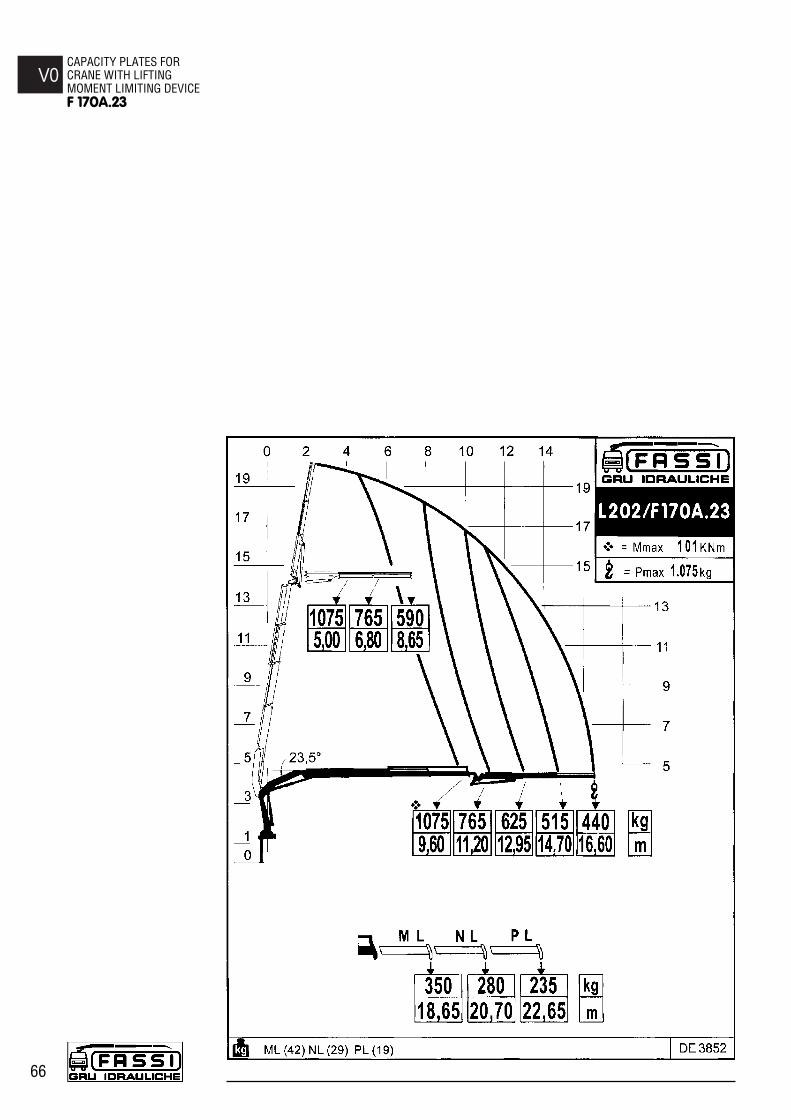
V0CAPACITY PLATES FOR CRANE WITH LIFTING MOMENT LIMITING DEVICEF 170A.23
66

V0CAPACITY PLATES FOR
CRANE WITH LIFTING MOMENT LIMITING DEVICE
F 170A.23
67

V1CAPACITY PLATES FORCRANE WITHOUT LIFTINGMOMENT LIMITING DEVICEF 170A.23
68
V1 CAPACITY PLATES FOR CRANE WITHOUTLIFTING MOMENT LIMITING DEVICE
For cranes and manual extensions.For cranes and manual extensions with winch.For hydraulic jib and manual extensions.For hydraulic jib and manual extensions with winch.
The represented plates refer to the nominal design capacities.
(!) WARNING (!)
If the capacities are downgraded or partially reduced (e.g. sector in front ofvehicle cab) capacity plates must be applied in line with the final test figures.

V1CAPACITY PLATES FOR
CRANE WITHOUT LIFTINGMOMENT LIMITING DEVICE
F 170A.23
69

V1CAPACITY PLATES FOR CRANEWITHOUT LIFTING MOMENTLIMITING DEVICEF 170A.23
70