Embed Size (px)
Citation preview
– for grease up to NLGI grade 2– with electric drives – for progressive and multiline systems
Piston Pumps with Reservoir1�0107�2�US
Quality ManagementDIN EN ISO 9001: 2000
Environmental ManagementDIN EN ISO 14001
Because of their delivery rates and reservoir capacities these grease pump units are designed to supply small� and medium�sizesystems. They come with 2 or 3 pump outlet ports.
The possible operating voltages are 90 to 264 V AC, 47 to 440 Hz, or 12 or 24 V DC.
Safety elements like pressure�limiting valves, overpressure indicators or rupture discs must be provided for in order to protect thepump unit from overloads. Information on this point can also be found in leaflet 1�0107�6�US, page 3 “Accessories”.
KFGS30�5KFA1 / KFA10 KFG1�5�W2�M
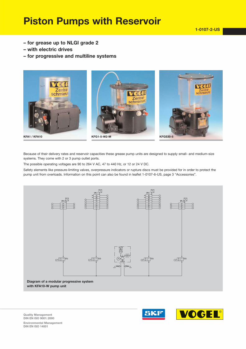
Diagram of a modular progressive systemwith KFA10�W pump unit
Piston pumps with grease reservoir · progressive systems 1�0107�2�US 2
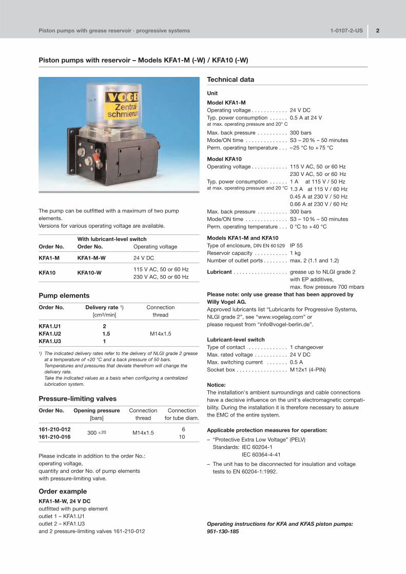
The pump can be outfitted with a maximum of two pump elements.Versions for various operating voltage are available.
With lubricant�level switchOrder No. Order No. Operating voltage
KFA1�M KFA1�M�W 24 V DC
KFA10 KFA10�W115 V AC, 50 or 60 Hz230 V AC, 50 or 60 Hz
Pump elements
Order No. Delivery rate 1) Connection[cm3/min] thread
KFA1.U1 2KFA1.U2 1.5 M14x1.5KFA1.U3 1
1) The indicated delivery rates refer to the delivery of NLGI grade 2 greaseat a temperature of +20 °C and a back pressure of 50 bars. Temperatures and pressures that deviate therefrom will change the delivery rate. Take the indicated values as a basis when configuring a centralized lubrication system.
Pressure�limiting valves
Order No. Opening pressure Connection Connection[bars] thread for tube diam.
161�210�012300 ±20 M14x1.5
6161�210�016 10
Please indicate in addition to the order No.:operating voltage,quantity and order No. of pump elements with pressure�limiting valve.
Order exampleKFA1�M�W, 24 V DCoutfitted with pump elementoutlet 1 – KFA1.U1outlet 2 – KFA1.U3 and 2 pressure�limiting valves 161�210�012
Technical data
Unit
Model KFA1�MOperating voltage . . . . . . . . . . . . 24 V DCTyp. power consumption . . . . . . 0.5 A at 24 Vat max. operating pressure and 20° C
Max. back pressure . . . . . . . . . . 300 barsMode/ON time . . . . . . . . . . . . . . S3 – 20 % – 50 minutesPerm. operating temperature . . . –25 °C to +75 °C
Model KFA10Operating voltage . . . . . . . . . . . . 115 V AC, 50 or 60 Hz
230 V AC, 50 or 60 HzTyp. power consumption . . . . . . 1 A at 115 V / 50 Hzat max. operating pressure and 20 °C 1.3 A at 115 V / 60 Hz
0.45 A at 230 V / 50 Hz0.66 A at 230 V / 60 Hz
Max. back pressure . . . . . . . . . . 300 barsMode/ON time . . . . . . . . . . . . . . S3 – 10 % – 50 minutesPerm. operating temperature . . . 0 °C to +40 °C
Models KFA1�M and KFA10Type of enclosure, DIN EN 60 529 IP 55Reservoir capacity . . . . . . . . . . . 1 kgNumber of outlet ports . . . . . . . . max. 2 (1.1 and 1.2)
Lubricant . . . . . . . . . . . . . . . . . . grease up to NLGI grade 2with EP additives,max. flow pressure 700 mbars
Please note: only use grease that has been approved by Willy Vogel AG. Approved lubricants list “Lubricants for Progressive Systems,NLGI grade 2”, see “www.vogelag.com” or please request from “info@vogel�berlin.de”.
Lubricant�level switchType of contact . . . . . . . . . . . . . 1 changeoverMax. rated voltage . . . . . . . . . . . 24 V DCMax. switching current . . . . . . . 0.5 ASocket box . . . . . . . . . . . . . . . . . M12x1 (4�PIN)
Notice:The installation's ambient surroundings and cable connectionshave a decisive influence on the unit's electromagnetic compati�bility. During the installation it is therefore necessary to assurethe EMC of the entire system.
Applicable protection measures for operation:
– “Protective Extra Low Voltage” (PELV)Standards: IEC 60204�1
IEC 60364�4�41
– The unit has to be disconnected for insulation and voltagetests to EN 60204�1:1992.
Operating instructions for KFA and KFAS piston pumps:951�130�185
Piston pumps with reservoir – Models KFA1�M (�W) / KFA10 (�W)
Piston pumps with grease reservoir · progressive systems 1�0107�2�US 3D
imen
sion
s in
mm
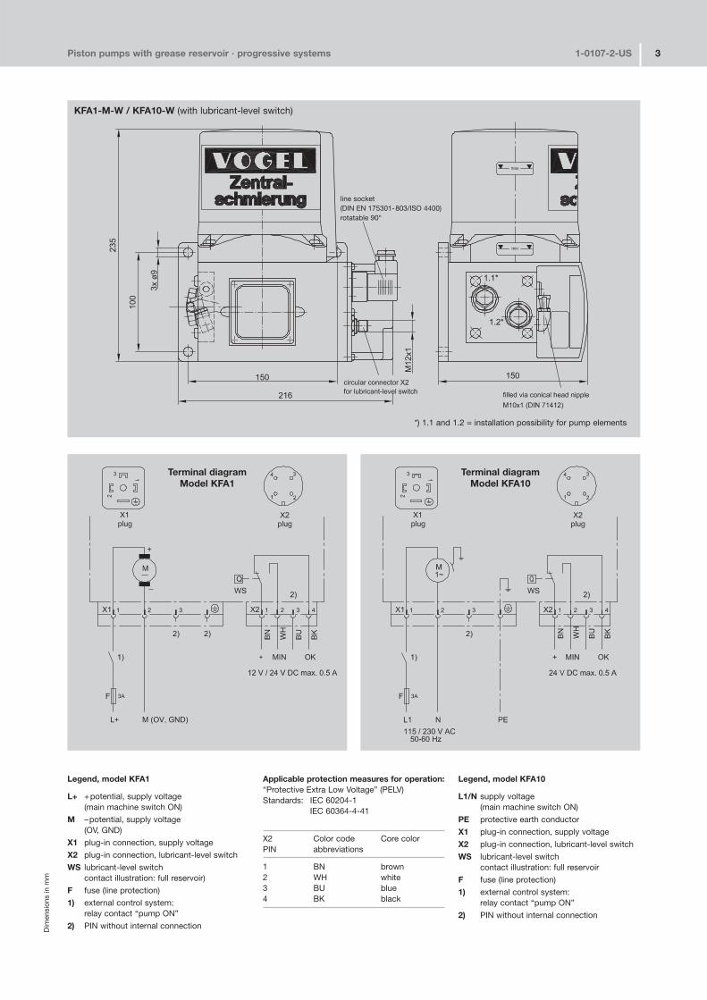
Legend, model KFA1
L+ +potential, supply voltage(main machine switch ON)
M –potential, supply voltage(OV, GND)
X1 plug�in connection, supply voltage
X2 plug�in connection, lubricant�level switch
WS lubricant�level switchcontact illustration: full reservoir)
F fuse (line protection)
1) external control system:relay contact “pump ON”
2) PIN without internal connection
Applicable protection measures for operation:“Protective Extra Low Voltage” (PELV)Standards: IEC 60204�1
IEC 60364�4�41
X2 Color code Core colorPIN abbreviations
1 BN brown2 WH white3 BU blue4 BK black
Legend, model KFA10
L1/N supply voltage(main machine switch ON)
PE protective earth conductor
X1 plug�in connection, supply voltage
X2 plug�in connection, lubricant�level switch
WS lubricant�level switchcontact illustration: full reservoir
F fuse (line protection)
1) external control system:relay contact “pump ON”
2) PIN without internal connection
KFA1�M�W / KFA10�W (with lubricant�level switch)
Terminal diagramModel KFA1
Terminal diagramModel KFA10
*) 1.1 and 1.2 = installation possibility for pump elements
line socket(DIN EN 175301�803/ISO 4400)rotatable 90°
Piston pumps with grease reservoir · progressive systems 1�0107�2�US 4
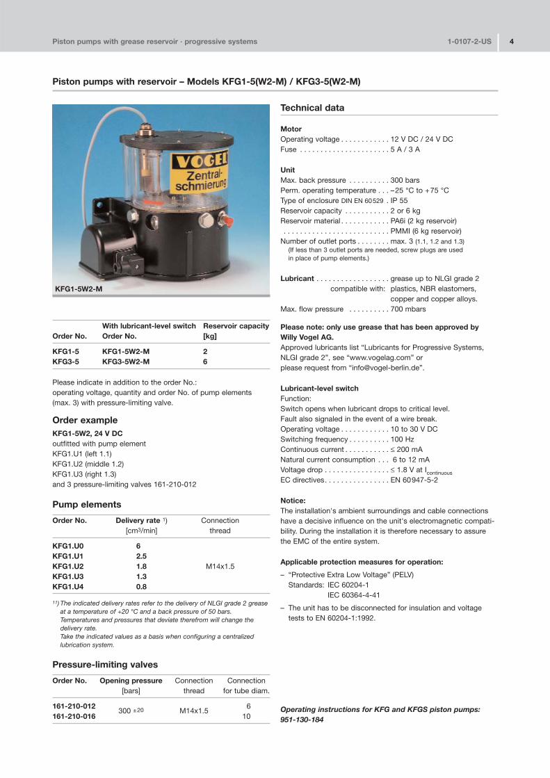
With lubricant�level switch Reservoir capacityOrder No. Order No. [kg]
KFG1�5 KFG1�5W2�M 2KFG3�5 KFG3�5W2�M 6
Please indicate in addition to the order No.:operating voltage, quantity and order No. of pump elements(max. 3) with pressure�limiting valve.
Order exampleKFG1�5W2, 24 V DCoutfitted with pump elementKFG1.U1 (left 1.1)KFG1.U2 (middle 1.2)KFG1.U3 (right 1.3)and 3 pressure�limiting valves 161�210�012
Pump elements
Order No. Delivery rate 1) Connection[cm3/min] thread
KFG1.U0 6KFG1.U1 2.5KFG1.U2 1.8 M14x1.5KFG1.U3 1.3KFG1.U4 0.8
11) The indicated delivery rates refer to the delivery of NLGI grade 2 greaseat a temperature of +20 °C and a back pressure of 50 bars. Temperatures and pressures that deviate therefrom will change the delivery rate. Take the indicated values as a basis when configuring a centralized lubrication system.
Pressure�limiting valves
Order No. Opening pressure Connection Connection[bars] thread for tube diam.
161�210�012300 ±20 M14x1.5
6161�210�016 10
Technical data
MotorOperating voltage . . . . . . . . . . . . 12 V DC / 24 V DCFuse . . . . . . . . . . . . . . . . . . . . . . 5 A / 3 A
UnitMax. back pressure . . . . . . . . . . 300 barsPerm. operating temperature . . . –25 °C to +75 °CType of enclosure DIN EN 60529 . IP 55Reservoir capacity . . . . . . . . . . . 2 or 6 kgReservoir material . . . . . . . . . . . . PA6i (2 kg reservoir). . . . . . . . . . . . . . . . . . . . . . . . . . PMMI (6 kg reservoir)
Number of outlet ports . . . . . . . . max. 3 (1.1, 1.2 and 1.3)(If less than 3 outlet ports are needed, screw plugs are used in place of pump elements.)
Lubricant . . . . . . . . . . . . . . . . . . grease up to NLGI grade 2compatible with: plastics, NBR elastomers,
copper and copper alloys.Max. flow pressure . . . . . . . . . . 700 mbars
Please note: only use grease that has been approved by Willy Vogel AG. Approved lubricants list “Lubricants for Progressive Systems,NLGI grade 2”, see “www.vogelag.com” or please request from “info@vogel�berlin.de”.
Lubricant�level switchFunction:Switch opens when lubricant drops to critical level.Fault also signaled in the event of a wire break.Operating voltage . . . . . . . . . . . . 10 to 30 V DCSwitching frequency . . . . . . . . . . 100 HzContinuous current . . . . . . . . . . . ≤ 200 mANatural current consumption . . . 6 to 12 mAVoltage drop . . . . . . . . . . . . . . . . ≤ 1.8 V at Icontinuous
EC directives. . . . . . . . . . . . . . . . EN 60947�5�2
Notice:The installation's ambient surroundings and cable connectionshave a decisive influence on the unit's electromagnetic compati�bility. During the installation it is therefore necessary to assurethe EMC of the entire system.
Applicable protection measures for operation:
– “Protective Extra Low Voltage” (PELV)Standards: IEC 60204�1
IEC 60364�4�41
– The unit has to be disconnected for insulation and voltagetests to EN 60204�1:1992.
Operating instructions for KFG and KFGS piston pumps:951�130�184
KFG1�5W2�M
Piston pumps with reservoir – Models KFG1�5(W2�M) / KFG3�5(W2�M)
Piston pumps with grease reservoir · progressive systems 1�0107�2�US 5D
imen
sion
s in
mm
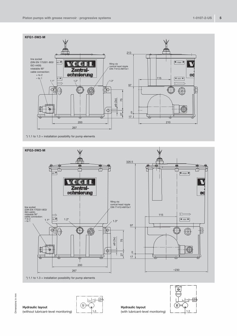
KFG1�5W2�M
KFG3�5W2�M
Hydraulic layout(without lubricant�level monitoring)
Hydraulic layout(with lubricant�level monitoring)
line socket(DIN EN 175301�803/ISO 4400)rotatable 90° cable connection:
+ to 2– to 1
*) 1.1 to 1.3 = installation possibility for pump elements
*) 1.1 to 1.3 = installation possibility for pump elements
Piston pumps with grease reservoir · progressive systems 1�0107�2�US 6
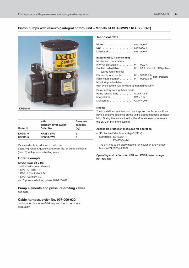
with Reservoirlubricant�level switch capacity
Order No. Order No. [kg]
KFGS1�5 KFGS1�5W2 2KFGS3�5 KFGS3�5W2 6
Please indicate in addition to order No.:operating voltage, quantity and order No. of pump elements(max. 3) with pressure�limiting valve.
Order exampleKFGS1�5W2, 24 V DCoutfitted with pump element1 KFG1.U1 (left 1.1)1 KFG1.U2 (middle 1.2)1 KFG1.U3 (right 1.3)and 3 pressure�limiting valves 161�210�012
Pump elements and pressure�limiting valvessee page 4
Cable harness, order No. 997�000�630, not included in scope of delivery and has to be ordered separately.
Technical data
Motor . . . . . . . . . . . . . . . . . . . . . see page 4Unit . . . . . . . . . . . . . . . . . . . . . . see page 4Lubricant . . . . . . . . . . . . . . . . . . see page 4
Integral IG502�I control unitModes and parametersInterval, adjustable . . . . . . . . . . . 0.1…99.9 hContact, adjustable . . . . . . . . . . 0.1…99.9 min or 1…999 pulses
(pump running time)Elapsed�hours counter . . . . . . . 0.1…99999.9 h
non�erasableFault�hours counter . . . . . . . . . . 0.1…99999.9 hMonitoring, adjustablewith cycle switch (CS) or without monitoring (OFF)
Basic factory setting: timer modePump running time . . . . . . . . . . tCO = 4 minInterval time . . . . . . . . . . . . . . . . tPA = 1 hMonitoring . . . . . . . . . . . . . . . . . COP = OFF
Notice:The installation's ambient surroundings and cable connectionshave a decisive influence on the unit's electromagnetic compati�bility. During the installation it is therefore necessary to assurethe EMC of the entire system.
Applicable protection measures for operation:
– “Protective Extra Low Voltage” (PELV)Standards: IEC 60204�1
IEC 60364�4�41
– The unit has to be disconnected for insulation and voltagetests to EN 60204�1:1992.
Operating instructions for KFG and KFGS piston pumps:951�130�184
KFGS1�5
Piston pumps with reservoir, integral control unit – Models KFGS1�5(W2) / KFGS3�5(W2)
Piston pumps with grease reservoir · progressive systems 1�0107�2�US 7D
imen
sion
s in
mm
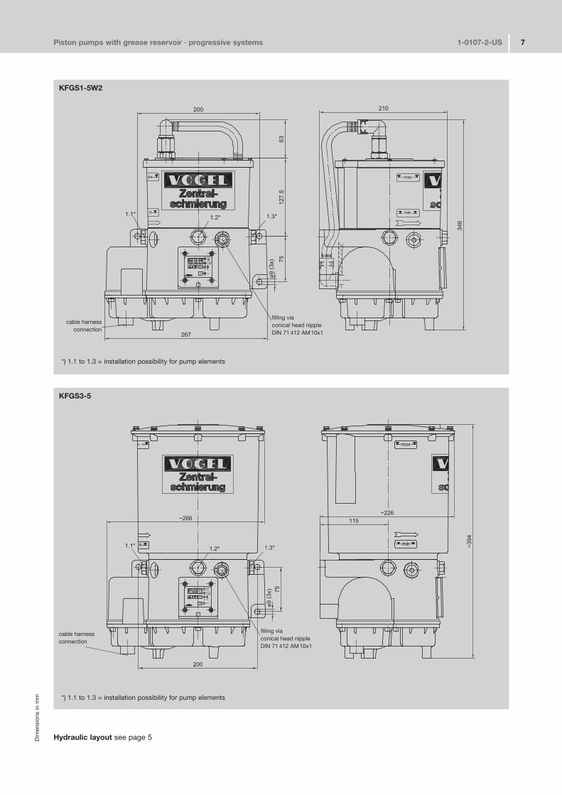
KFGS1�5W2
KFGS3�5
Hydraulic layout see page 5
*) 1.1 to 1.3 = installation possibility for pump elements
*) 1.1 to 1.3 = installation possibility for pump elements
filling viaconical head nippleDIN 71 412 AM10x1
filling viaconical head nippleDIN 71 412 AM10x1
cable harnessconnection
cable harnessconnection
Piston pumps with grease reservoir · progressive systems 1�0107�2�US 8
with Reservoirlubricant�level switch capacity
Order No. Order No. [kg]
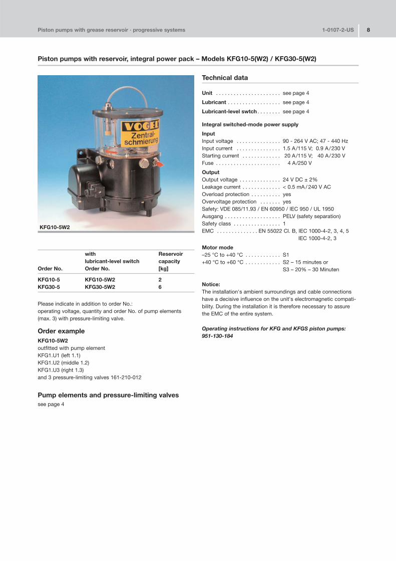
KFG10�5 KFG10�5W2 2KFG30�5 KFG30�5W2 6
Please indicate in addition to order No.:operating voltage, quantity and order No. of pump elements(max. 3) with pressure�limiting valve.
Order exampleKFG10�5W2outfitted with pump elementKFG1.U1 (left 1.1)KFG1.U2 (middle 1.2)KFG1.U3 (right 1.3)and 3 pressure�limiting valves 161�210�012
Pump elements and pressure�limiting valvessee page 4
Technical data
Unit . . . . . . . . . . . . . . . . . . . . . . see page 4
Lubricant . . . . . . . . . . . . . . . . . . see page 4
Lubricant�level swtch . . . . . . . . see page 4
Integral switched�mode power supply
InputInput voltage . . . . . . . . . . . . . . . 90 � 264 V AC; 47 � 440 HzInput current . . . . . . . . . . . . . . . 1.5 A/115 V; 0.9 A/230 VStarting current . . . . . . . . . . . . . 20 A/115 V; 40 A/230 VFuse . . . . . . . . . . . . . . . . . . . . . . 4 A/250 V
OutputOutput voltage . . . . . . . . . . . . . . 24 V DC ± 2%Leakage current . . . . . . . . . . . . . < 0.5 mA / 240 V ACOverload protection . . . . . . . . . . yesOvervoltage protection . . . . . . . yesSafety: VDE 085/11.93 / EN 60950 / IEC 950 / UL 1950Ausgang . . . . . . . . . . . . . . . . . . . PELV (safety separation)Safety class . . . . . . . . . . . . . . . . 1EMC . . . . . . . . . . . . . . EN 55022 Cl. B, IEC 1000�4�2, 3, 4, 5
IEC 1000�4�2, 3
Motor mode–25 °C to +40 °C . . . . . . . . . . . . S1+40 °C to +60 °C . . . . . . . . . . . . S2 – 15 minutes or
S3 – 20% – 30 Minuten
Notice:The installation's ambient surroundings and cable connectionshave a decisive influence on the unit's electromagnetic compati�bility. During the installation it is therefore necessary to assurethe EMC of the entire system.
Operating instructions for KFG and KFGS piston pumps:951�130�184
KFG10�5W2
Piston pumps with reservoir, integral power pack – Models KFG10�5(W2) / KFG30�5(W2)
Piston pumps with grease reservoir · progressive systems 1�0107�2�US 9D
imen
sion
s in
mm
line socket(DIN EN 175301�803/ISO 4400)rotatable 90°
filling viaconical head nippleDIN 71 412 AM10x1
filling viaconical head nippleDIN 71 412 AM10x1
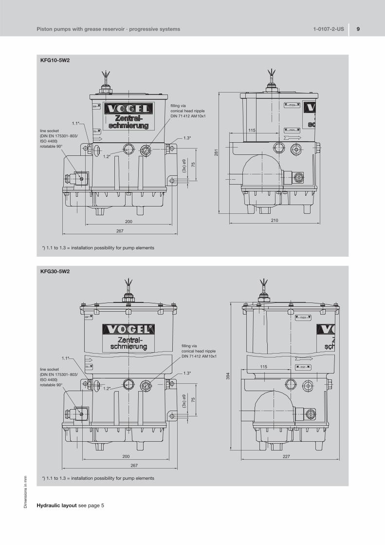
KFG30�5W2
KFG10�5W2
Hydraulic layout see page 5
line socket(DIN EN 175301�803/ISO 4400)rotatable 90°
*) 1.1 to 1.3 = installation possibility for pump elements
*) 1.1 to 1.3 = installation possibility for pump elements
Piston pumps with grease reservoir · progressive systems 1�0107�2�US 10
with Reservoirlubricant�level switch capacity
Order No. Order No. [kg]
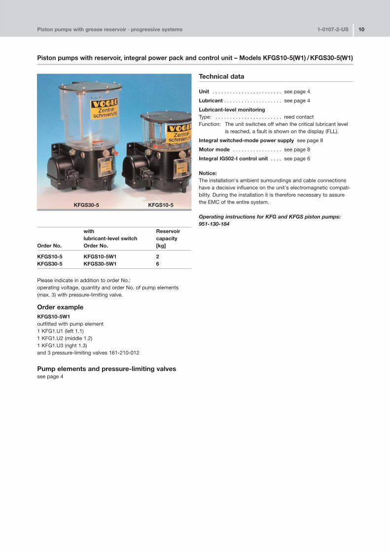
KFGS10�5 KFGS10�5W1 2KFGS30�5 KFGS30�5W1 6
Please indicate in addition to order No.:operating voltage, quantity and order No. of pump elements(max. 3) with pressure�limiting valve.
Order exampleKFGS10�5W1outfitted with pump element1 KFG1.U1 (left 1.1)1 KFG1.U2 (middle 1.2)1 KFG1.U3 (right 1.3)and 3 pressure�limiting valves 161�210�012
Pump elements and pressure�limiting valvessee page 4
Technical data
Unit . . . . . . . . . . . . . . . . . . . . . . . . see page 4
Lubricant . . . . . . . . . . . . . . . . . . . . see page 4
Lubricant�level monitoringType: . . . . . . . . . . . . . . . . . . . . . . . reed contactFunction: The unit switches off when the critical lubricant level
is reached, a fault is shown on the display (FLL).
Integral switched�mode power supply see page 8
Motor mode . . . . . . . . . . . . . . . . . see page 8
Integral IG502�I control unit . . . . see page 6
Notice:The installation's ambient surroundings and cable connectionshave a decisive influence on the unit's electromagnetic compati�bility. During the installation it is therefore necessary to assurethe EMC of the entire system.
Operating instructions for KFG and KFGS piston pumps:951�130�184
Piston pumps with reservoir, integral power pack and control unit – Models KFGS10�5(W1) /KFGS30�5(W1)
KFGS30�5 KFGS10�5
Piston pumps with grease reservoir · progressive systems 1�0107�2�US 11D
imen
sion
s in
mm
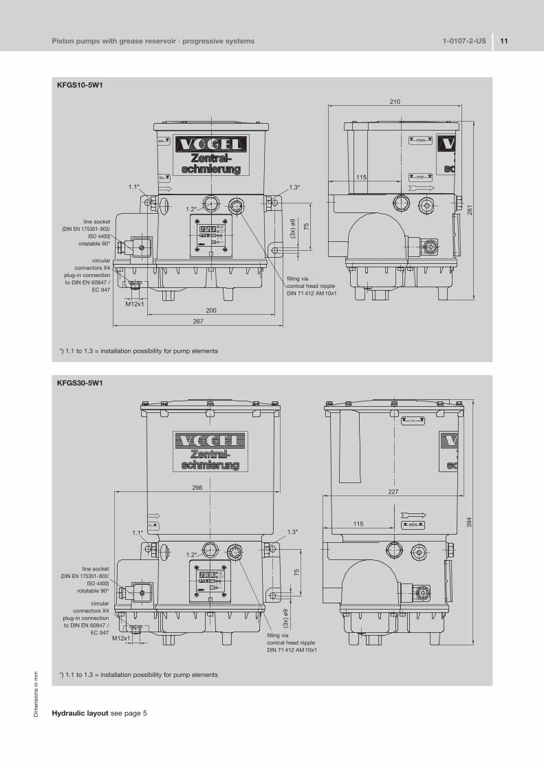
KFGS30�5W1
KFGS10�5W1
line socket(DIN EN 175301�803/
ISO 4400)rotatable 90°
filling viaconical head nippleDIN 71 412 AM 10x1
circular connectors X4
plug�in connection to DIN EN 60947 /
EC 947
circular connectors X4
plug�in connection to DIN EN 60947 /
EC 947 filling viaconical head nippleDIN 71 412 AM 10x1
line socket(DIN EN 175301�803/
ISO 4400)rotatable 90°
Hydraulic layout see page 5
*) 1.1 to 1.3 = installation possibility for pump elements
*) 1.1 to 1.3 = installation possibility for pump elements
Leaflet information
1�0107�1�US Progressive Feeders1�0107�4�US Grease Pump Units (models PF, PFP, PFH)1�4002�1�US Motor Pump Unit GSJBDSK 2�008�00�US Grease Pump Unit FFDSK 2�005�00�US Grease Pump Unit FB1�0107�5�US Piston Pumps (Typ PPU, PHU)1�0107�6�US Accessories for Progressive Systems
Piston pumps with grease reservoir · progressive systems 1�0107�2�US 12
Sub
ject
to
chan
ge w
ithou
t no
tice!
0000
01/
2006
Notice!
All products from VOGEL may be used only for their intended purpose. If operating instructions are supplied together with the products, the provi�sions and information therein of specific relevance to the equipment mustbe observed as well.
In particular, we call your attention to the fact that hazardous materials ofany kind, especially the materials classified as hazardous by EC Directive67/548/EEC, Article 2, Par. 2, may only be filled into VOGEL centralized lubrication systems and components and delivered and/or distributed withthe same after consultation with and written approval from VOGEL.
All products manufactured by VOGEL are not approved for use in con�junction with gases, liquefied gases, pressurized gases in solution andfluids with a vapor pressure exceeding normal atmospheric pressure (1013 mbars) by more than 0.5 bar at their maximum permissible temperature.
Willy Vogel AGMotzener Strasse 35/3712277 Berlin, GermanyP.O.Box 970444 ·12704 Berlin
Tel. +49 (0) 30 72002�0Fax +49 (0) 30 72002�111info@vogel�berlin.dewww.vogelag.com
Willy Vogel AG2. Industriestrasse 468766 HockenheimGermany
Tel. +49 (0) 6205 27�0Fax +49 (0) 6205 27�132info@vogel�berlin.dewww.vogelag.com
Vogel France SASRue Robert Amy, B.P. 7013049404 Saumur cedexFrance
Tel. +33 (0) 241 404 200Fax +33 (0) 241 404 [email protected]