Embed Size (px)
Citation preview

III B.TECH II SEMESTER
LECTURE NOTESon
ENVIRONMENTAL ENGINEERINGPrepared by
Mr. Srinivas AngadiAsst. Professor in Civil Engineering

Unit –I:
Protected Water Supply - Population
Forecasts, Design Period - Water Demand -
Types Of Demand - Factors Affecting
Fluctuations - Fire Demand - Storage
Capacity - Water Quality And Testing -
Drinking Water Standards. Comparison from
Quality and Quantity and Other
Considerations – Intakes - Infiltration
Galleries, Confined and Unconfined Aquifers,
Distribution Systems - Requirements -
Methods and Layouts.
Unit –II:
Layout and general outline of water treatmentunits - sedimentation, uniform settling velocity –principles - design factors - surface loading - Jar test-optimum dosage of coagulant – coagulation -flocculation, clarifier design - coagulants - feedingarrangements. Filtration – theory - working of slowand rapid gravity filters - multimedia filters - designof filters - troubles in operation comparison of filters- disinfection - Types of disinfection - theory ofchlorination- chlorine demand and other disinfectiontreatment methods. Distribution systems - types oflayouts of distribution systems - Design ofdistribution systems - Hardy Cross and equivalentpipe methods, Service reservoirs – joints, valves suchas sluice valves, air valves, scour valves and checkvalves water meters - laying and testing of pipe lines-pump house.

Unit –III:
Conservancy and water carriage systems -sewage and storm water estimation - type ofconcentration - storm water over flowscombined flow - characteristics of sewage,cycles of decay - decomposition of sewage,examination of sewage, B.O.D. and C.O.D.equations - design of sewers - shapes andmaterials - sewer appurtenances manhole -inverted siphon - catch basins - flushing tanks -ejectors, pumps and pump houses- housedrainage - components requirements - sanitaryfittings - traps- one pipe and two pipe systems ofplumbing – ultimate disposal of sewage – sewagefarming – dilution

Unit –IV:
Lay out and general outline of various units
in a waste water treatment plant –primary
treatment design of screens –grit chambers –
skimming tanks-sedimentation tanks-
principles and design of biological treatment
–trickling filters- standard and high rate.
Unit –V:
Construction and design of oxidation ponds
–sludge digestion tanks –factors effecting –
design of digestion tank –sludge disposal by
drying –septic tanks working principles and
design-soak pits. Ultimate disposal of waste
water- self purification of rivers- sewage
farming.
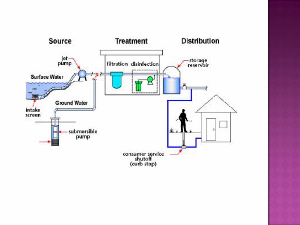
The main function of the intakes works is tocollect the water from various sources. Thesources may be lakes, rivers, reservoirs andcanals. The intake work for each type of sourceis designed separately according to itsrequirements and situations.
Intakes are structures which essentially consistof opening, grating through which the raw waterfrom source and is carried to a sump-well bymeans of conduits.
Water from the sump well is pumped through therising mains to the treatment plant.


The best quality of water should be available at the
site so that it can be easily and economically
purified in less time to the treatment plants.
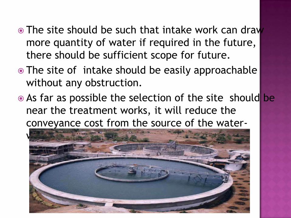
The site should be such that intake work can draw
more quantity of water if required in the future,
there should be sufficient scope for future.
The site of intake should be easily approachable
without any obstruction.
As far as possible the selection of the site should be
near the treatment works, it will reduce the
conveyance cost from the source of the water-
works.
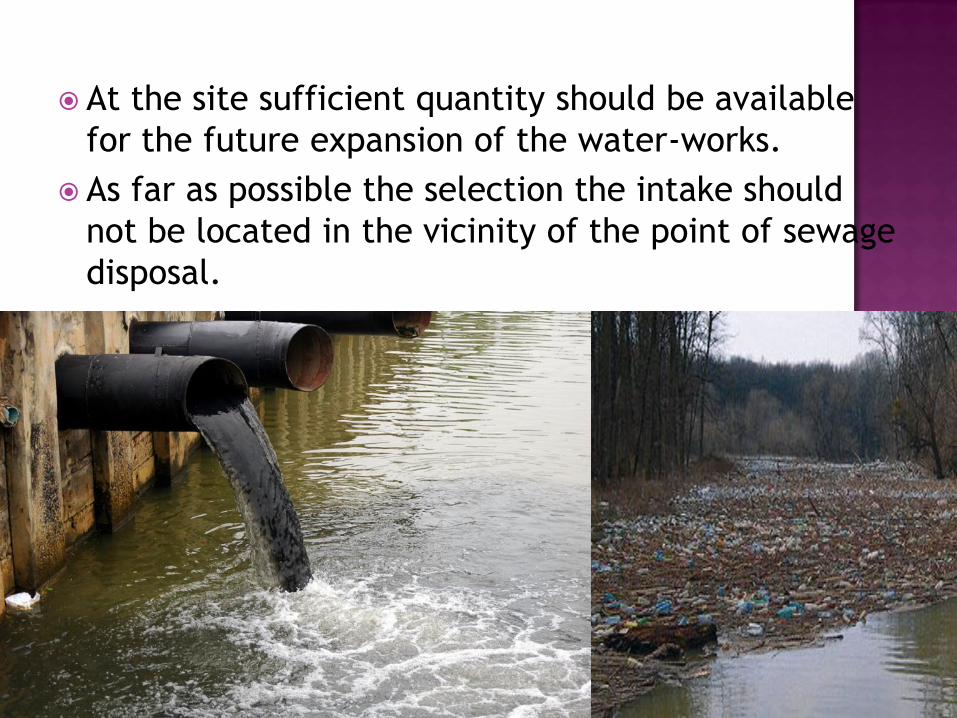
At the site sufficient quantity should be available
for the future expansion of the water-works.
As far as possible the selection the intake should
not be located in the vicinity of the point of sewage
disposal.

The intake work for each type of source is
designed separately according to the
requirements and situations, Depending on the
source of water in intake works are classified as
follows:
1. Lake intake
2. River intake
3. Reservoir intake
4. Canal intake
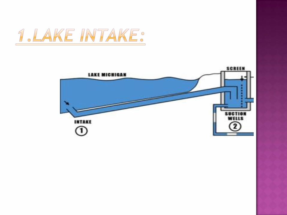
For obtaining water from lakes mostly submersible intakes
are used.
These intakes are constructed in the bed of the lake below
the slow water level so as to draw water in dry season also.
It essentially consists of a pipe laid in the bed of the river at
one end, which is in the middle of the lake is fitted with bell
mouth opening covered with mesh and protected by concrete
blocks.
The water enters in the pipe through the bell mouth opening
and flows under gravity to the bank where it is collected in
sump-well and then pumped to treatment plant.
If one pipe is not sufficient two or more pipes may be laid to
get the required quantity of water.

As these intakes draw small quantity of water, these
are not used on big water supply schemes like rivers
or reservoirs.

Water from the rivers is always drawn from the upstream side, because it is free from the contamination caused by the disposal of sewage in it.
It has circular masonary tower 4 to 7m in diaconstructed along the bank of the river at such place from where required quantity of water can be obtained even in the dry period.
The water enters in the lower portion of the intake known as sump-well from penstocks.
The penstocked are fitted with screens to check the entry of floating solids.
Number of penstock opening are provided in the intake tower to admit water at different levels.
The opening and closing of penstock valves is done with the help of wheels provided at the pump-house floor.
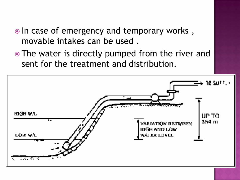
In case of emergency and temporary works ,
movable intakes can be used .
The water is directly pumped from the river and
sent for the treatment and distribution.


Reservoir intakes which mostly used to draw the water from earthern dam reservoir. It essentially consists of an intake tower constructed on the slope of the dam at such place from where intake can draw sufficient quantity of water even in the driest period.
Intake pipes are fixed at different levels, so as to draw water near the surface in all variations of water level.
These all inlet pipes are connected to one vertical pipe inside the intake well.
Screens are provided at the mouth of all intakes pipes to prevent the entrance of floating and suspended mstter in them.
The water which enters the vertical pipe is taken to the other side of the dam by means of outlet pipe.
At the top of the intake tower sluice valves are provided to control the flow of water.


Canal intake is a very simple structure constructed on the bank.
It essentially consists of a pipe placed in a brick masonry chamber constructed partly in the canal bank.
Other side of chambers as opening is provided with coarse screen for the entrance of water.
The pipe in side chamber is provided with a bell-mouth fitted with a a hemispherical fine screen,
The out-let pipe carries the water to the other side of the canal bank from where it is taken to the treatment plants.
One sluice valve which is operated by a wheel from the top of the masonry chamber is provided to control the flow of water in pipe.


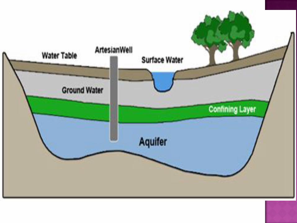
AQUIFERS
An aquifer is an underground layer of water-bearing
permeable rock or unconsolidated materials (gravel,
sand, or silt) from which groundwater can be
extracted using a water well.
The study of water flow in aquifers and the
characterization of aquifers is called hydrogeology.

Geological material through which significant
quantities of water can not move, located
below unconfined aquifers, above and below confined
aquifers. Also known as a confining bed.

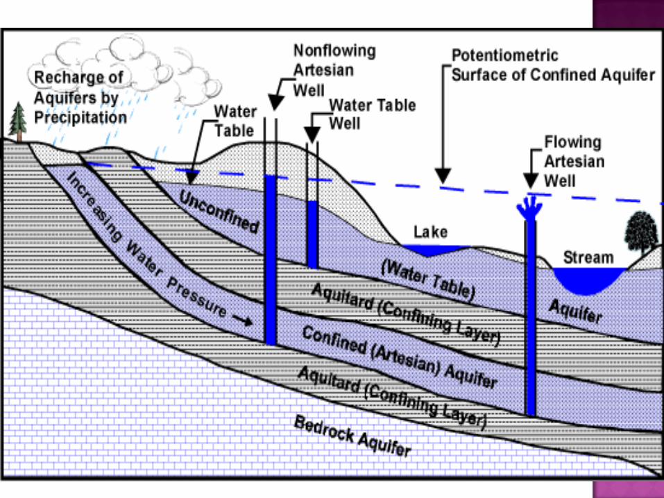
Confined aquifers are those in which
an impermeable dirt/rock layer exists that prevents
water from seeping into the aquifer from the ground
surface located directly above.

Unconfined aquifers are those into which water seeps
from the ground surface directly above the aquifer.

Unconfined aquifers:
Natural recharge of the unconfined aquifers is mainly
due to the downward seepage (or percolation) through
the unsaturated zone of the excess water over passing
the field capacity of the soil. Recharge can also occur
through upward seepage (leakage) from underlying
aquifers.

Confined aquifers:
A regional confined aquifer is directly recharged by
precipitation in the area where the aquifer crops out,
having the same characteristics as an unconfined
aquifer.

Infiltration galleries is a conduit,
built in permeable earth, for collecting ground water.
We have seen earlier that ground water travels
towards lakes, rivers or streams. This water which is
travelling can be intercepted by digging a trench or by
constructing a tunnel with holes on sides at right angle
to the direction of flow.
These underground tunnel used for tapping
underground water near rivers, lakes or streams are
called “INFILTRATION GALLERIES”.
These are also known as Horizontal walls.


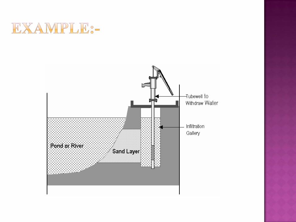

Infiltration galleries can be used to collect sub-surface
flow from rivers. Water is taken to a collective well, or
sump, and then pumped to a storage tank.
Infiltration galleries vary in size, from a few meters
feeding into spring box, to many kilometers forming an
integral part of unban water supply.

To ensure a continuous supply of water , infiltration
galleries should be built in the end of dry season and
should be at least one meter under the dry season
water table.
Excavate a trench to at least 1 m below the water
table,
Lay graded gravel on the base of the trench.
Lay the pipe or drain blocks on top of the gravel.
Cover the top and sides with more graded gravel.
Cap the gravel with an impermeable layer of clay to
prevent surface water entering the gallery.


TREATMENT PLANT


Settling is the process by which particulates settle to the
bottom of a liquid and form a sediment.
Particles that experience a force, either due to gravity
or due to centrifugal motion will tend to move in a
uniform manner in the direction exerted by that force.

Size, shape and specific gravity of the particles.
Discrete particle settling - Particles settle individually
without interaction with neighboring particles.
Flocculent Particles – Flocculation causes the particles
to increase in mass and settle at a faster rate.
Hindered or Zone settling –The mass of particles tends
to settle as a unit with individual particles remaining in
fixed positions with respect to each other.
The purpose of a Water Treatment Plant is
to remove particulates and pathogens from water that
may pose a health threat to consumers.


The Principles of Water and Wastewater Treatment
Processes has been divided into the following Units:
Water Quality
Physical Processes:
Microbes and other colloidal particles can be physically removed from
water by various processes. The sizes of the microbes are especially
important for their removal by sedimentation and filtration.
Chemical Processes:
Calcium hydroxide (hydrated lime) (Ca(OH)2):
Is dosed at the start and end of the treatment process.
The pre-dose increases the alkalinity for optimal coagulation as well as the
hardness and buffering capacity of water (resistance to change in pH).
The post-dose is to raise the pH to within drinking water guidelines and the
optimum level for the residual disinfectant.

Sludge Treatment:
Sludge is produced from the treatment of wastewater
in on-site (e.g. septic tank) and off-site (e.g. activated sludge)
systems. The primary aim of wastewater treatment is removing
solids from the wastewater.
Odour Management:
Wastewater treatment plant odours are common. Perimeter odour
neutralising spray systems can be used to great effect to
control wastewater treatment plant odours.
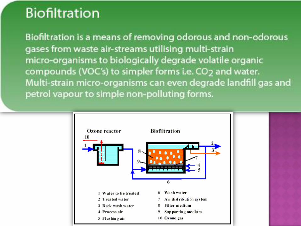
( Biofiltration systems can treat several
contaminants simultaneously, without the use of chemicals.
With 95% odour removal efficiency, our biofiltration systems
can treat a wide range of contaminants. )

Calculating the surface loading gives a guide to how much
water can be processed each day per area of sedimentation
tank.
Surface loading is one of the most important factors affecting
the effectiveness of the sedimentation process. The surface
loading rate is used to determine if the sedimentation tanks and
clarifiers are under loaded or over loaded.
If actual surface loading is > the design values then this
indicates the tanks are overloaded.
If actual surface loading is < the design values then this
indicates the tanks are underloaded.

The surface loading test calculates the volume of water being
treated over a period of time over surface area of the tank.
surface loading (kL per day per m2) = flow rate (kL per day)
surface area of tank (m2)

Aeration (also called aerification) is the process by which
air is circulated through, mixed with or dissolved in a
liquid or substance.
Passing the liquid through air by means
of fountains, cascades, paddle-wheels or cones.

Production of aerated water for drinking purposes.
Secondary treatment of sewage or
industrial wastewater through use of aerating
mixers/diffusers.
To increase the oxygen content of water used to house
animals, such as aquarium fish or fish farm.
In chemistry, to oxidise a compound dissolved or
suspended in water.


As the quality of source water varies daily in every
season, it is necessary that the water samples for
analysis should be collected frequently.
According to the quality of water it should be
treated.
The following are the tests which are done
During water quality test:
a) Physical test.
b) Chemical test.
c) Biological test.
1.TEMPERATURE: The temperature of water is measured by means of ordinary thermometers.
From the temperature the MASS density(P=m/v), viscosity, vapour pressure and surface tension of water can be determined.
The temperature of surface water is generally same to the atmospheric temperature, while that of ground water may be more or less than atmospheric temperature.
The most desirable temperature for public supply is between 4.4 °c to 10 °c.
Temperature above 28 °c are undesirable and above 35 °c are unfit for public supply, because it is NOT PALATABLE(NOT ACCECTABLE TO TASTE).

2.COLOUR: The color of water is usually due to presence of organic matter, but sometimes it is also due to mineral and dissolved organic and inorganic impurities.
Before testing the color of the water, first of all total suspended matter should be removed from the water by centrifugal force in a special apparatus.
After this the color of water is compared with standard color solution.
The permissible color for domestic water is 20p.p.m on platinium cobalt scale.
The color in water is not harmful but it is objectionable.

3. TURBIDITY: It is caused due to presence of
suspended and colloidal matter in the water.
The character and amount of turbidity depends
on the type of soil over which the water has
moved.
There are two types of turbidimeters:
1) Based on visual method( through naked eye).
2) Based on direct (meter reading ) method.

In the chemical testing of water those test are done that will reveal the sanitary quality of the water.
The chemical test involve the determination of total solids, hardness, chlorides, iron and manganese etc.
1. Total solids: Total solids is a measure of the suspended and
dissolved solids in water.
• The quantity of suspended solids is determined byfiltering the sample of water through a fine filter, dryingand weighing.
• The quantity of dissolved and colloidal solids isdetermined by evaporating the filtered water(obtainedfrom the suspended solid test) and weighing the water.
• The total solids in a water sample can be directlydetermined by evaporating the water and weighing it.
• By weighing we can determine the inorganic solids anddeducting it from total solids.

It is the property of water which prevents the lathering
(form ) of the soap.
It is caused due to the presence of carbonates and sulphates
of calcium and magnesium in the water.
Also in the presence of chlorides and nitrates of calcium and
magnesium cause hardness in the water.
Hardness is usually expressed in mg/lit or p.p.m of calcium
carbonate in water.
In the past the hardness was determined by soap test, in
which the standard soap sol was added in the water and it
was shaked to see the formation of lather for 5 min. The
hardness of water was calculated on the basis of soap
solution added and lather factor.


The natural water near the sea or mines have
dissolve sodium chloride(Nacl).
The presence of chlorides may be due to the mixing
of saline water (Saline water is water that contains a
significant concentration of dissolved salts (mainly NaCl)
and is commonly known as saltwater) and sewage in the
water.
Excess of chlorides is dangerous and unfit for use.
The chloride can be reduced by diluting the a water.
Chlorides above 250p.p.m are not permissible(not
allowed) in water.
The chloride can be determined by titrating the
water with silver nitrate(Agno3) and potassium
chromate(k2cro4), in that titration process reddish
colour will be formed if chlorides are present.

These are generally found in ground water. If these
are present less than 0.3 p.p.m. it is not
objectionable . But it exceeds 0.3p.p.m the water is
not suitable for domestic and laundering purposes.
The presence of iron and manganese in water makes
brownish red colour in it, leads to growth of micro-
organisms. Iron and manganese also cause taste and
odour in the water.
The quality of iron and manganese is determined by
colorimetric methods.
In these methods some colouring agents are added in
the water and compared with standard colour
solutions.

In general, a water with a pH < 7 is considered acidic and with a pH > 7 is considered basic.
The normal range for pH in surface water systems is 6.5 to 8.5 and for groundwater systems 6 to 8.5.
Alkalinity is a measure of the capacity of the water to resists a change in pH that would tend to make the water more acidic.
PH SCALE
0 TO 7 7 Slightly above 7 to 14
(Acidic range) (Alkaline range)

In a biological test the following two tests are done:-
a) TOTAL COUNT OF BACTERIA:- In this method total number
of bacteria present in millimeter of water is counted. The
sample of water is taken, 1 ml of sample water is diluted in
99ml of sterilized water.
1.Sterilized Water (absence of any bacteria in the water).
2.Distilled water (that has many of its impurities removed through
distillation. Distillation involves boiling the water and then
condensing the steam into a clean container).
• This mixture is kept in incubator at 37°c for 24hrs.
• After it the sample will be taken out from incubator and
counted by means of microscope.

b) BACTERIA COLI(B-COLI)TEST:
There are 2 tests B-coli first is presumptive and second
confirmative.
In the presumptive test definite amount of diluted sample of
the water in standard fermentation tubes is kept in
inclubator at 37°c for 24hrs. If some gas is produced in the
fermentation tube , indicates the presence of B-coli.
And it again kept in incubator at 37°c for 48 hrs, if there is
formation of gas in the tube , it confirms the presence of B-
coli and the water is unsafe to use.
This method is known as “MEMBRANE FILTER TECHNIQUE”.

A wastewater treatment plant is a physical plant
where various physical, biological or chemical
processes are used to change the properties of
the wastewater (e.g. by removing harmful
substances) in order to turn it into a type of water
(also called effluent) that can be safely discharged
into the environment or that is usable for a
certain reuse purpose.
By-products from wastewater treatment
plants, such as screenings, sewage sludge,
odorous gases are also treated in a wastewater
treatment plant.


The purpose of preliminary treatment is to protect the
operation of the wastewater treatment plant which can
damage pumps, or interfere with subsequent treatment
processes. Preliminary treatment devices are, therefore,
designed to:
1.Remove or to reduce in size the large, entrained, suspended
or floating solids. These solids consist of pieces of wood,
cloth, paper, plastics, garbage, etc. together with some
fecal matter.
Pre-chlorination is a process that involves adding chlorine to the collection system of industrial plants and other Treatment plant, mainly for corrosion and odor control.
It is also applied for the purpose of disinfection and for the removal of oil particles.
It is also used in water treatment to control aquatic growth as well as taste, and as aid in settling and coagulation.
In pre-chlorination, chlorine is added to the raw water prior to flash mixing and post screening.
The excess chlorine is beneficial in the various stages of treatment by:
1.Aiding coagulation
2.Controlling of algae problems
3.Reducing odor and mud ball formation

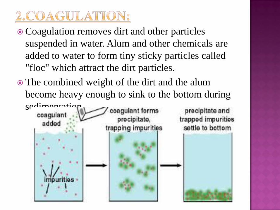
Coagulation removes dirt and other particles
suspended in water. Alum and other chemicals are
added to water to form tiny sticky particles called
"floc" which attract the dirt particles.
The combined weight of the dirt and the alum
become heavy enough to sink to the bottom during
sedimentation.


Solids are removed by sedimentation (settling) followed
by filtration. Small particles are not removed efficiently by
sedimentation because they settle too slowly; they may also
pass through filters. They would be easier to remove if they
clumped together (coagulated) to form larger particles, but
they don't because they have a negative charge and repel each
other (like two north poles of a magnet).
In coagulation, we add a chemical such as alum which
produces positive charges to neutralize the negative charges
on the particles. Then the particles can stick together, forming
larger particles which are more easily removed.
The coagulation process involves the addition of the chemical
(e.g. alum) and then a rapid mixing to dissolve the chemical
and distribute it evenly throughout the water.

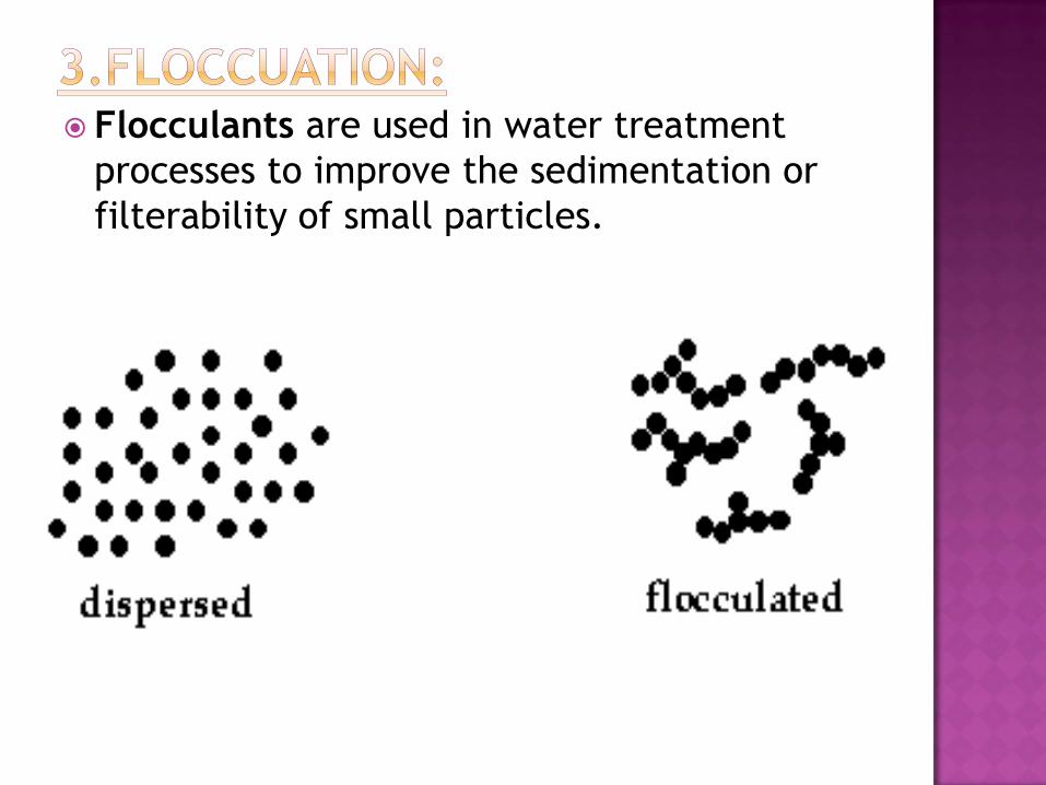
Flocculants are used in water treatment
processes to improve the sedimentation or
filterability of small particles.

A soft or fluffy particle suspended in a liquid
or the fluffy mass of suspended particles so
formed. Floc may be mineral as
for clay, chemical as in water
treatment or biological as in sewage
treatment.

Sedimentation is a physical watertreatment process using gravity toremove suspended solids from water.
The particles that settle out from the suspensionbecome sediment, and in water treatment isknown as sludge. When a thick layer of sedimentcontinues to settle, this is known as consolidation.
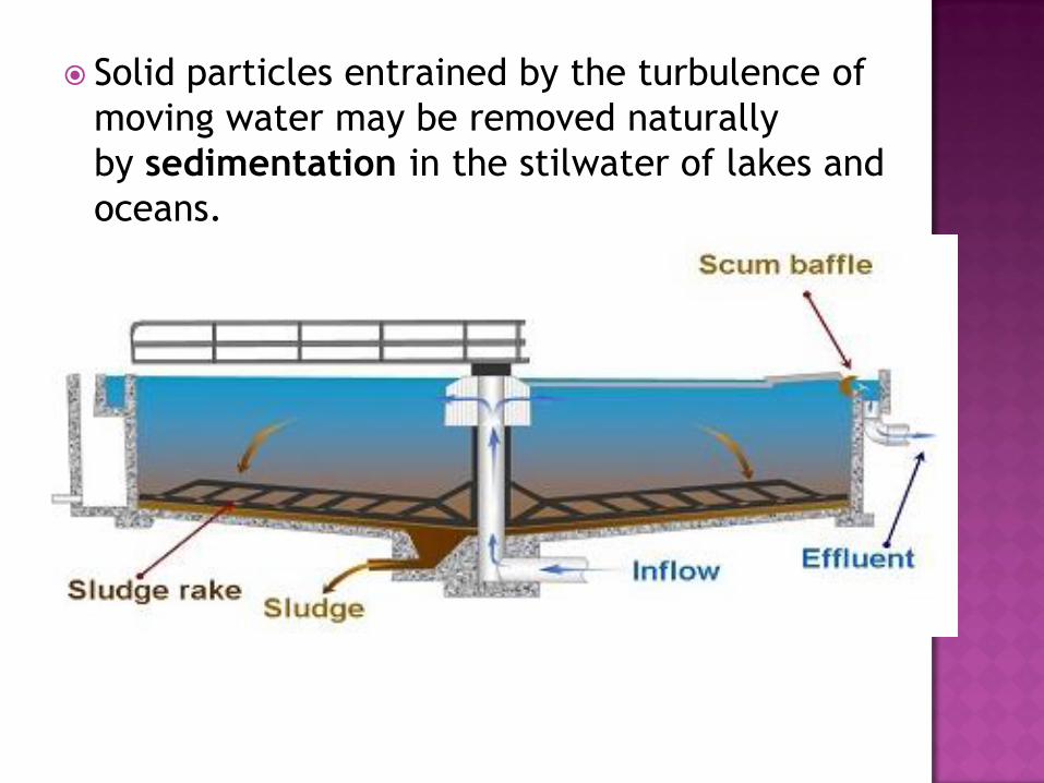
Solid particles entrained by the turbulence of
moving water may be removed naturally
by sedimentation in the stilwater of lakes and
oceans.

Sand filters are used for water purification.
There are three main types;
Rapid (gravity) sand filters.
Sand filtration is a frequently used very strong
method to remove suspended solids from
water.

Post Chlorination is the final process in water
treatment.
The chlorine will kill any bacteria or viruses
remaining in the water and it is important that a
minimum level of chlorination remains in the water
through the storage and distribution.
If needed, additional chorine is added to the finished
water that leaves the water plants. Low levels of
chlorine (approximately 0.2 to 1.0 part per million)
must be maintained in the distribution systems pipes
and home plumbing to prevent the growth of
microorganisms.

Water fluoridation is the controlled addition
of fluoride to a public water supply to reduce tooth
decay.
Water fluoridation is the addition of the
chemical fluoride to public water supplies, for the
purpose of reducing cavities.`


Water purification is the removal of contaminants from untreated
water to produce drinking water that is pure enough for the most
critical of its intended uses, usually for human consumption.
Measures taken to ensure water quality not only relate to the
treatment of the water, but to its conveyance and distribution after
treatment as well.


Distribution system is the part of the water
works which receives the water from the
pumping station in the form of gravity flow
or pumping system and delivers it
throughout the town which is to be served.
The distribution system consists of pipes of
various sizes, valves, meters, pumps,
distribution reservoirs, hydrants etc.


The pipe lines carry the water to each and every street,
road.
Valves control the flow of water through the pipes.
Meters are provided to measure the quantity of water
consumed by the town.
Hydrants are provided to connect the water to the fire
fighting equipments during fire.
Service connections are done to connect the individual
building with the water line passing through the streets.
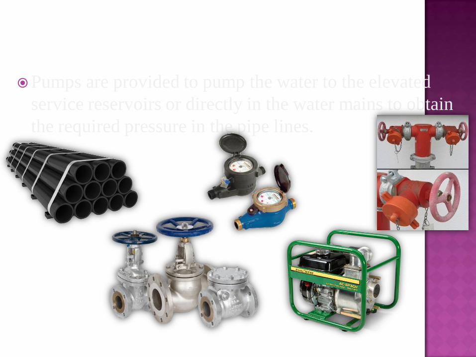
Pumps are provided to pump the water to the elevated
service reservoirs or directly in the water mains to obtain
the required pressure in the pipe lines.

It should convey the treated water up to the consumers with the same degree of purity.
The water should reach to every consumer with the required pressure head.
Sufficient quantity of treated water should reach for the domestic and industrial use.
It should be able to transport sufficient quantity of water during emergency such as fire- fighting.
It should be reliable so that even during breakdown or repairs of one line water should reach that locality from other line.

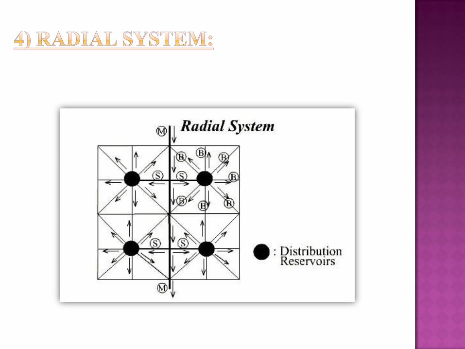
Generally there are four different systems of distribution which
are used,
Depending upon their layout and direction of supply, they are
classified as follows:
1.Dead end or tree system.
2.Grid Iron system.
3.Circular or ring system.
4.Radial system.


Depending upon the methods of distribution
, the distribution system is classified as
follows:
1. Gravity system
2. Pumping system
3. Dual system or combined gravity and
pumping system.
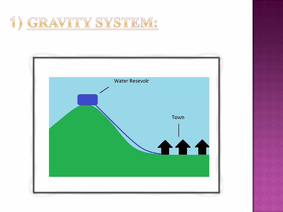

This method is much suitable when source of supply
such as lake, river or impounding reservoir is at sufficient
height than city.
The water flows in the mains due to gravitational force,
as no pumping is required, therefore it is most reliable
system for the distribution of water.
In this system usually pumping is not required at any
stage, in case the source of water supply is lake situated
at the hill, low lifting pumping is required to lift the water
up to water treatment plant.

ADVANTAGES:
This will reduce the
Leakage and waste to the
Minimum.
DISADVANTAGES:
But in case of fire attack the water had to be pumped.

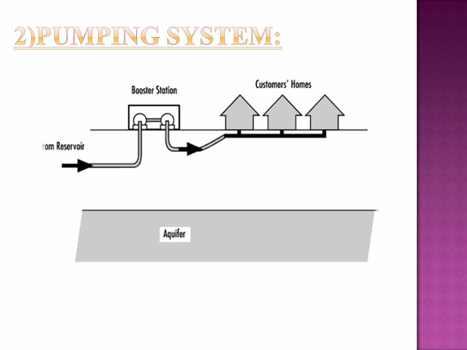

High lift pumps are required and their operations are
continuously watched.
If power fails, the whole supply of the town will be
stopped, therefore it is better to have diesel pumps also in
addition to the electric pumps as stand bye.
ADVANTAGE:
During fires, the water can be pumped in the required
quantity by the stand-bye units also.


This is the combination of both gravity and pumping system.
The pump is connected to the mains as well as to an elevated
reservoir.
In the beginning when water demand is small the water is
stored in the elevated reservoir, but when demand increases
the rate of pumping, the flow in the distribution system comes
from the both the pumping station as well as from elevated
reservoir.


ADVANTAGES:
This system is more reliable and economical.
The water stored in elevated reservoir meets the requirements
of demand during breakdown of pumps and for fire fighting.
The balance reserve in the storage reservoir will be utilized
during fire. In case the fire demand is more, and if required
the water supply of few localities may be closed.

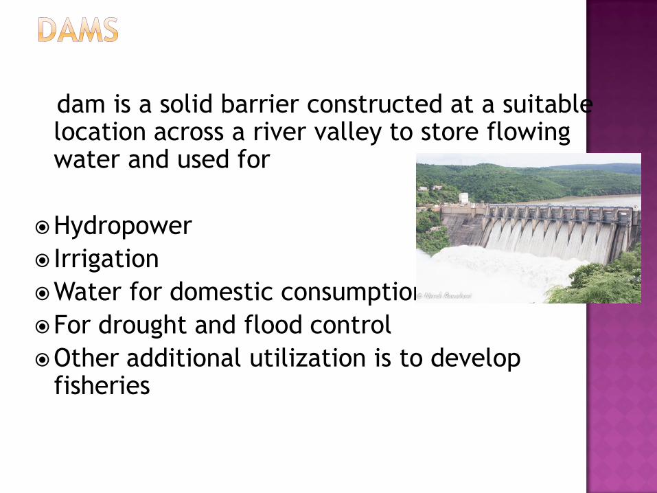
dam is a solid barrier constructed at a suitable location across a river valley to store flowing water and used for
Hydropower
Irrigation
Water for domestic consumption
For drought and flood control
Other additional utilization is to develop fisheries

there are four types of dams. They are
Arch dam
Gravity dam
Buttress dam
Earth dam
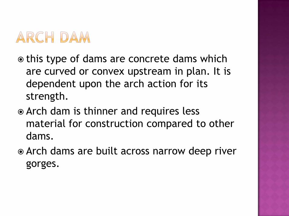
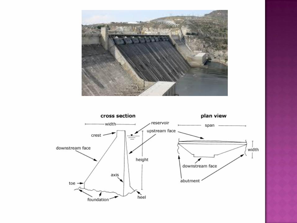
this type of dams are concrete dams which
are curved or convex upstream in plan. It is
dependent upon the arch action for its
strength.
Arch dam is thinner and requires less
material for construction compared to other
dams.
Arch dams are built across narrow deep river
gorges.


Gravity dams are the dams which resist the
horizontal thrust of water entirely by their
own weight
they use their weight to hold back the water
in the reservoir
Made of earth or rock fill or concrete

Buttress dams are dams in which the face is
held up by a series of supports.
Buttress dams can take many forms – the
face may be flat or curved.
Usually buttress dams are made of concrete
and may be reinforced with steel bars.

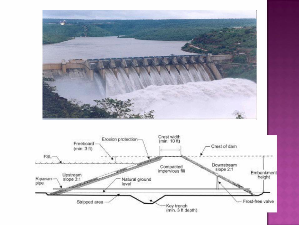
Earth dams are trapezoidal in shape
Earth dams are constructed where the
foundation rocks are weak to support
Earth dams are relatively smaller in height
and broad at the base
They are mainly built with clay, sand and
gravel. Hence they are also known as Earth
fill dam or Rock fill dam

DISTRIBUTION
SYSTEM

Type of flow- whether continuous or intermittent.
Method of distribution- whether by gravity or by pumping.
Probable future demand based on increase in population.
This also includes the industrial demand as well as fire –
fighting requirements.
Period to be considered in with life of pipes used. The
system should be designed anticipating the future of the
town or city.


Hydraulic Gradient: A line joining the points of highest
elevation of water in a series of vertical pipes rising from
a pipeline in which water flows under pressure.
According to HAZEN- WILLIAMS the flow-formula is
written as:
V=velocity of flow in pipe m/sec.
M= radius of the pipe in m.
I= Hydraulic gradient.
C=friction coefficient whose valve depends on
type of pipe used.

0.63 0.54
V = 0.85 C . M . I
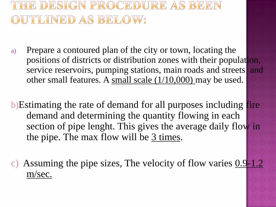
a) Prepare a contoured plan of the city or town, locating the positions of districts or distribution zones with their population, service reservoirs, pumping stations, main roads and streets and other small features. A small scale (1/10,000) may be used.
b)Estimating the rate of demand for all purposes including fire demand and determining the quantity flowing in each section of pipe lenght. This gives the average daily flow in the pipe. The max flow will be 3 times.
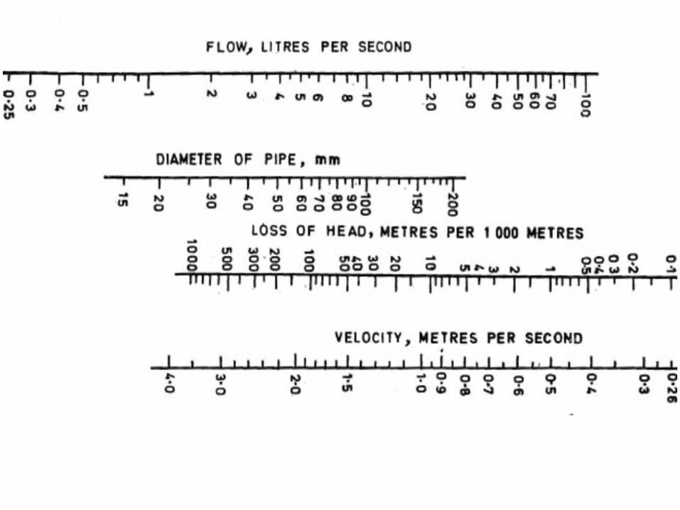
c) Assuming the pipe sizes, The velocity of flow varies 0.9-1.2 m/sec.
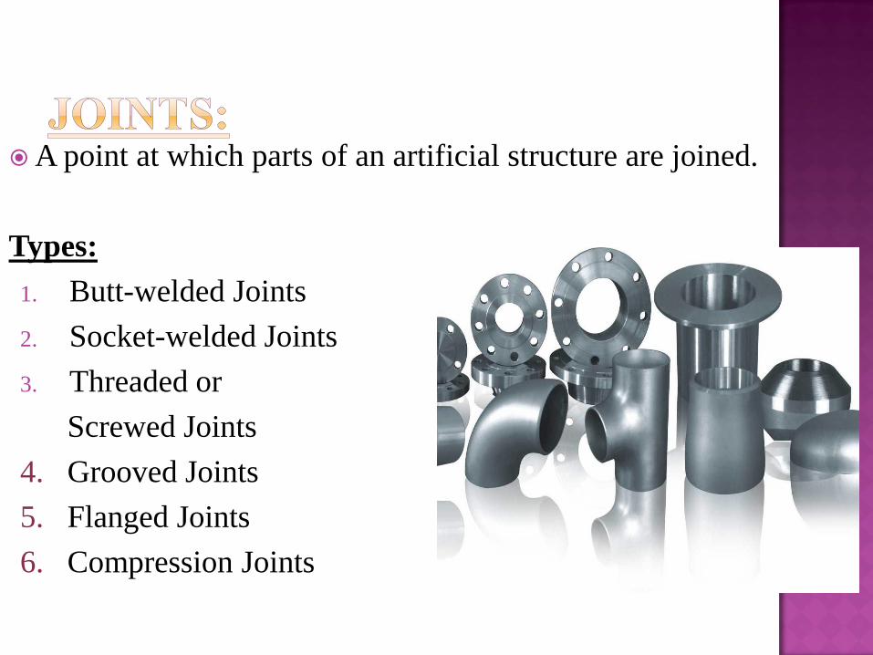
A point at which parts of an artificial structure are joined.
Types:
1. Butt-welded Joints
2. Socket-welded Joints
3. Threaded or
Screwed Joints
4. Grooved Joints
5. Flanged Joints
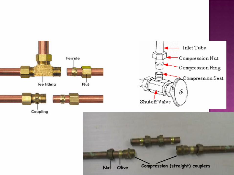
6. Compression Joints

Butt-welding is the most common
method of joining piping used
in large commercial, institutional,
and industrial piping systems.
Material costs are low, but labor costs are moderate to high due
to the need for specialized welders and fitters.
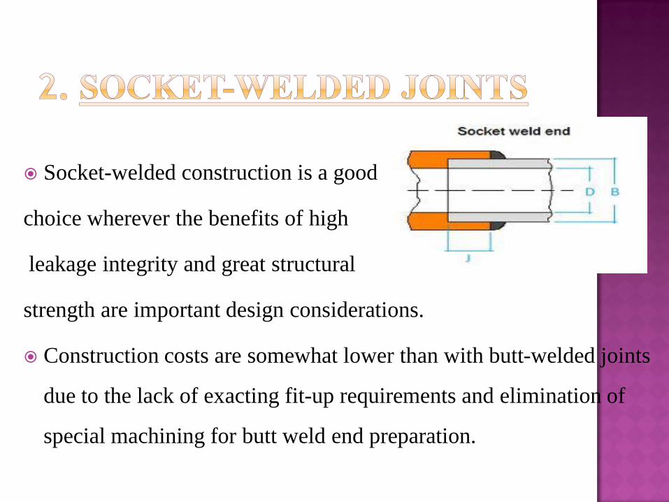
Socket-welded construction is a good
choice wherever the benefits of high
leakage integrity and great structural
strength are important design considerations.
Construction costs are somewhat lower than with butt-welded joints
due to the lack of exacting fit-up requirements and elimination of
special machining for butt weld end preparation.
Threaded or screwed piping is commonly used in low-
cost, noncritical applications
such as domestic water, fire protection, and industrial
cooling water systems.
Installation productivity is moderately high, and
specialized installation skill requirements
are not extensive.
Rapid temperature changes may
lead to leaks due to differential thermal expansion
between the pipe and fittings.


The main advantages of the grooved joints are
their ease of assembly, which results
in low labor cost, and generally good leakage
integrity.
They allow a moderate
amount of axial movement due to thermal
expansion, and they can accommodate
some axial misalignment.
The grooved construction prevents the joint
from separating under pressure.


Flanged connections are used extensively in modern
piping systems due to their ease of assembly and
disassembly; however, they are costly.
Contributing to the high cost are the material costs of
the flanges themselves and the labor costs for
attaching the flanges to the pipe and then bolting the
flanges to each other.
Flanges are normally attached to the pipe by
threading or welding, although in some special
cases a flange-type joint known as a lap joint may be
made by forging and machining
the pipe end.

Compression sleeve-type joints are used to join plain
end pipe without special end
preparations.
These joints require very little installation labor and as
such result
in an economical overall installation. Advantages
include the ability to absorb a
limited amount of thermal expansion and angular
misalignment and the ability to
join dissimilar piping materials, even if their outside
diameters are slightly different.