Embed Size (px)
Citation preview
Experimental Modelling of Alumina Particulates in Solid Booster ESA Clean Space Industrial Days 24-26 October 2017, ESTEC, Netherlands
> ESA CleanSpace Industrial Days > Saile et al. • Experimental Modelling of Alumina Particulates in Solid Booster > 24-26 October 2017 DLR.de • Chart 1
Table of Content
> ESA CleanSpace Industrial Days > Saile et al. • Experimental Modelling of Alumina Particulates in Solid Booster > 24-26 October 2017 DLR.de • Chart 2
• Introduction • Motivation • Requirements by ESA • Team
• Methods
• Test Environment • Wind Tunnel Model • Solid Propellant
• Measurement Techniques & Measurement Concept
• Conclusions

Ozone depletion of stratosphere
• Heterogeneous reactions, in particular chlorine activation reactions, take place on the surface of alumina particles.
• This mechanism potentially doubles the annually averaged total ozone depletion attributed to the emission of SRMs.
• In literature, there exists a discrepancy in regarding the particle size distribution.
• Research question concerns particle size and to provide benchmark data to describe particle formation processes.
Introduction Motivation
> ESA CleanSpace Industrial Days > Saile et al. • Experimental Modelling of Alumina Particulates in Solid Booster > 24-26 October 2017 DLR.de • Chart 3
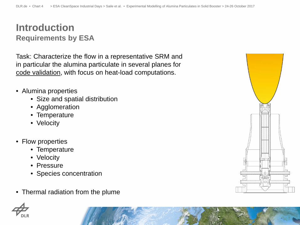
Task: Characterize the flow in a representative SRM and in particular the alumina particulate in several planes for code validation, with focus on heat-load computations.
• Alumina properties
• Size and spatial distribution • Agglomeration • Temperature • Velocity
• Flow properties
• Temperature • Velocity • Pressure • Species concentration
• Thermal radiation from the plume
Introduction Requirements by ESA
> ESA CleanSpace Industrial Days > Saile et al. • Experimental Modelling of Alumina Particulates in Solid Booster > 24-26 October 2017 DLR.de • Chart 4
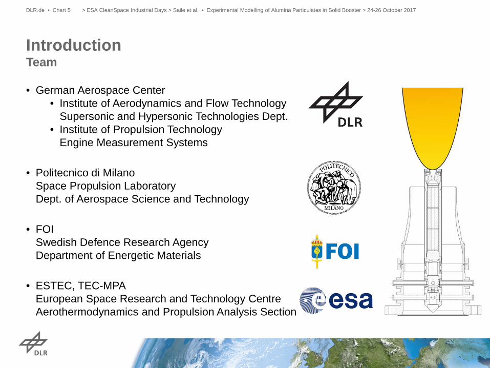
• German Aerospace Center
• Institute of Aerodynamics and Flow Technology Supersonic and Hypersonic Technologies Dept.
• Institute of Propulsion Technology Engine Measurement Systems
• Politecnico di Milano
Space Propulsion Laboratory Dept. of Aerospace Science and Technology
• FOI Swedish Defence Research Agency Department of Energetic Materials
• ESTEC, TEC-MPA European Space Research and Technology Centre Aerothermodynamics and Propulsion Analysis Section
Introduction Team
> ESA CleanSpace Industrial Days > Saile et al. • Experimental Modelling of Alumina Particulates in Solid Booster > 24-26 October 2017 DLR.de • Chart 5
> ESA CleanSpace Industrial Days > Saile et al. • Experimental Modelling of Alumina Particulates in Solid Booster > 24-26 October 2017 DLR.de • Folie 6
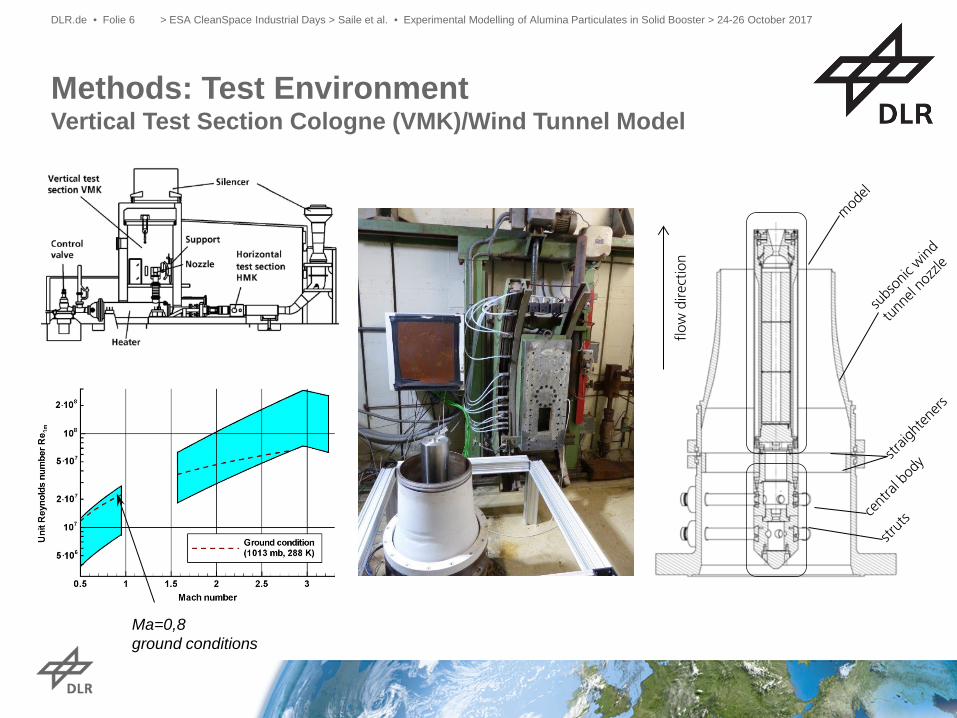
Methods: Test Environment Vertical Test Section Cologne (VMK)/Wind Tunnel Model
flow
dire
ctio
n
Ma=0,8 ground conditions
> ESA CleanSpace Industrial Days > Saile et al. • Experimental Modelling of Alumina Particulates in Solid Booster > 24-26 October 2017 DLR.de • Folie 7
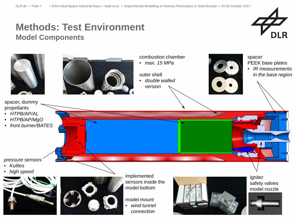
Methods: Test Environment Model Components
spacer, dummy propellants • HTPB/AP/AL • HTPB/AP/MgO • front burner/BATES
combustion chamber • max. 15 MPa outer shell • double walled
version
pressure sensors • Kulites • high speed
spacer PEEK base plates • IR measurements
in the base region
implemented sensors inside the model bottom model mount • wind tunnel
connection
igniter safety valves model nozzle
> EMAP: Introduction for MSQR > D. Saile et al. > Cologne, 23.05.2016 DLR.de • Folie 8
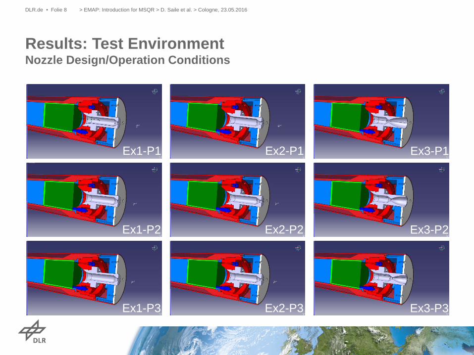
Ex1-P1
Ex1-P2
Ex1-P3
Ex2-P1
Ex2-P2
Ex2-P3
Ex3-P1
Ex3-P2
Ex3-P3
Results: Test Environment Nozzle Design/Operation Conditions
> ESA CleanSpace Industrial Days > Saile et al. • Experimental Modelling of Alumina Particulates in Solid Booster > 24-26 October 2017 DLR.de • Folie 9
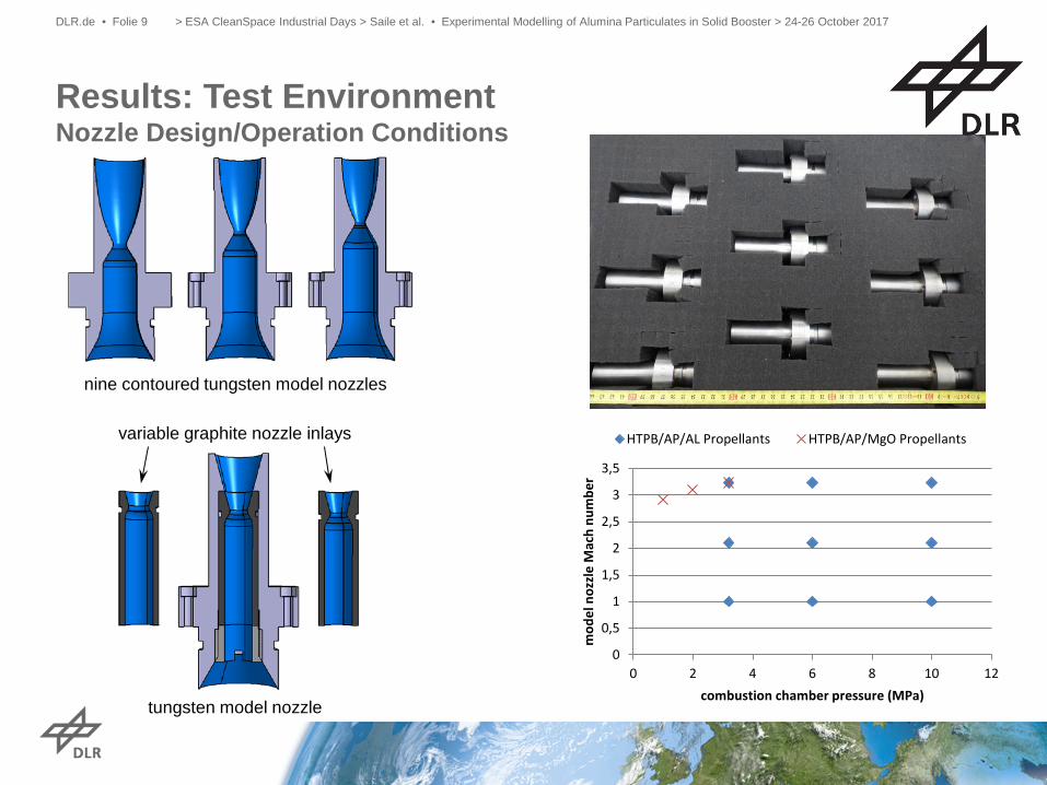
Results: Test Environment Nozzle Design/Operation Conditions
0
0,5
1
1,5
2
2,5
3
3,5
0 2 4 6 8 10 12
mod
el n
ozzl
e M
ach
num
ber
combustion chamber pressure (MPa)
HTPB/AP/AL Propellants HTPB/AP/MgO Propellants
nine contoured tungsten model nozzles
tungsten model nozzle
variable graphite nozzle inlays
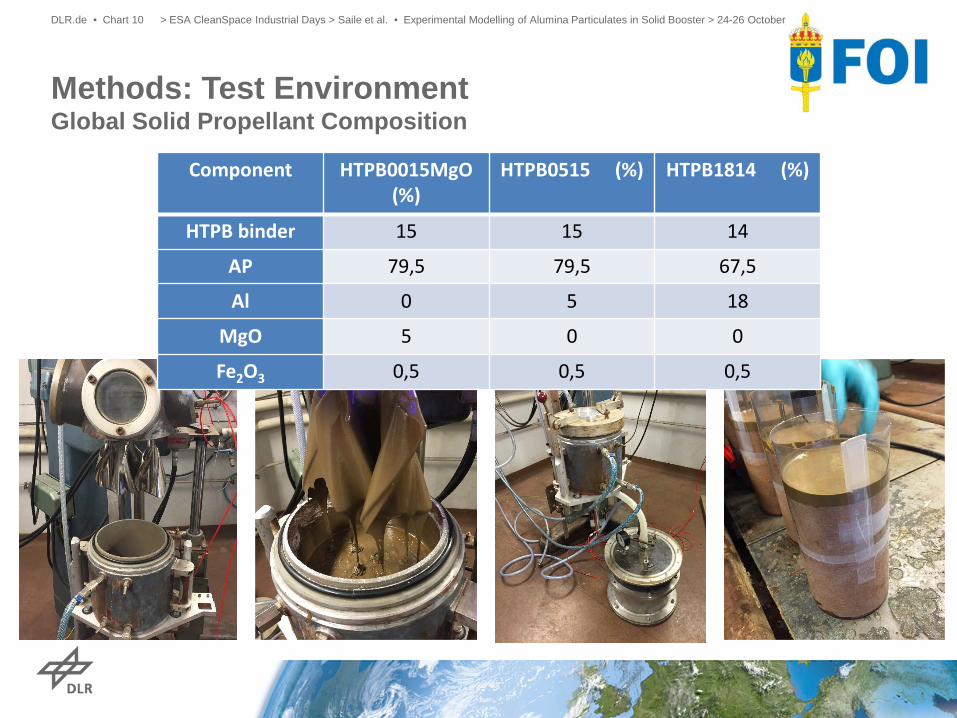
Methods: Test Environment Global Solid Propellant Composition
> ESA CleanSpace Industrial Days > Saile et al. • Experimental Modelling of Alumina Particulates in Solid Booster > 24-26 October 2017 DLR.de • Chart 10
Component HTPB0015MgO (%)
HTPB0515 (%) HTPB1814 (%)
HTPB binder 15 15 14
AP 79,5 79,5 67,5
Al 0 5 18
MgO 5 0 0
Fe2O3 0,5 0,5 0,5
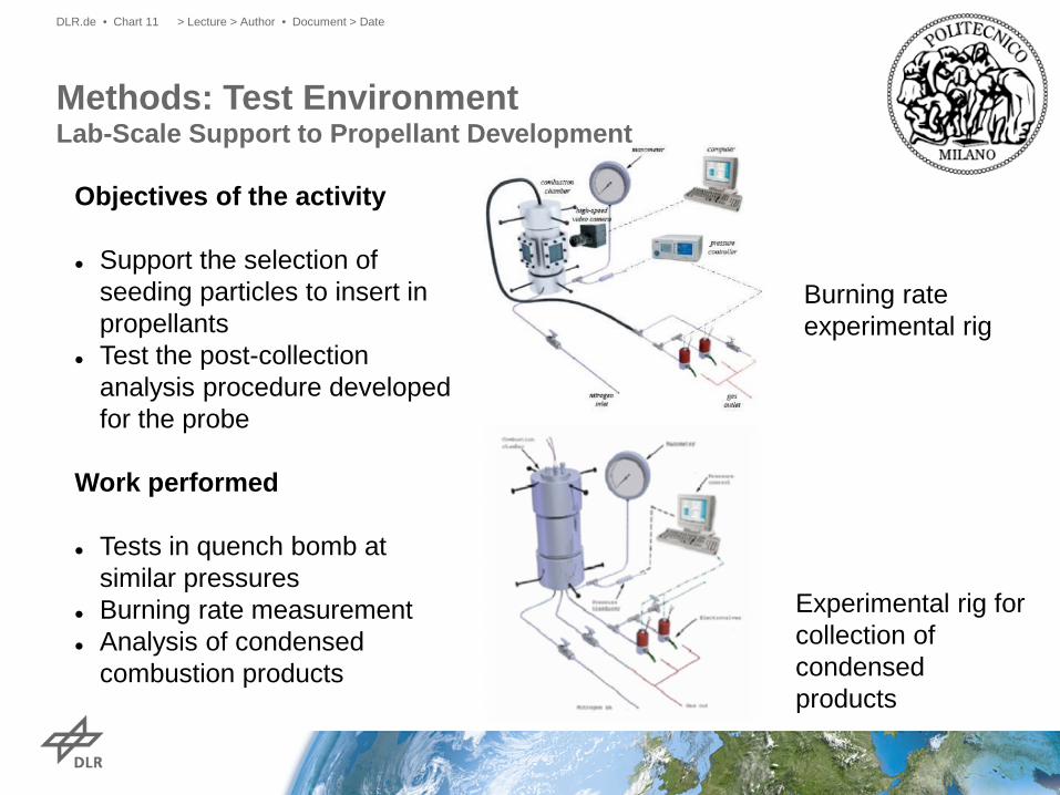
Methods: Test Environment Lab-Scale Support to Propellant Development
> Lecture > Author • Document > Date DLR.de • Chart 11
Objectives of the activity Support the selection of
seeding particles to insert in propellants
Test the post-collection analysis procedure developed for the probe
Work performed
Tests in quench bomb at similar pressures
Burning rate measurement Analysis of condensed
combustion products
Burning rate experimental rig
Experimental rig for collection of condensed products
> Lecture > Author • Document > Date DLR.de • Chart 12
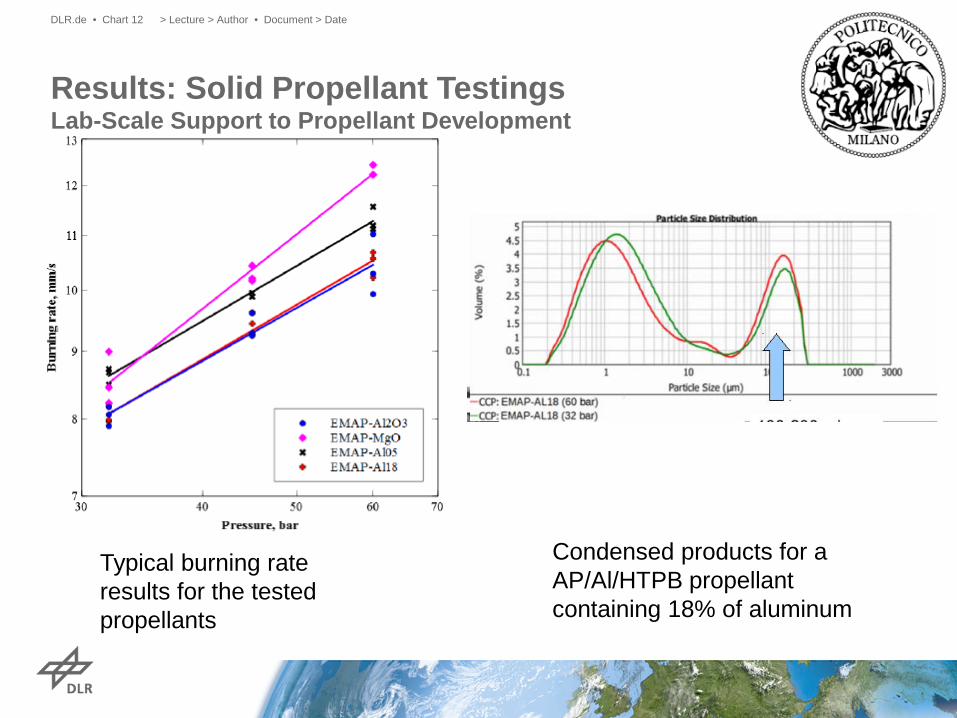
Typical burning rate results for the tested propellants
Condensed products for a AP/Al/HTPB propellant containing 18% of aluminum
Results: Solid Propellant Testings Lab-Scale Support to Propellant Development
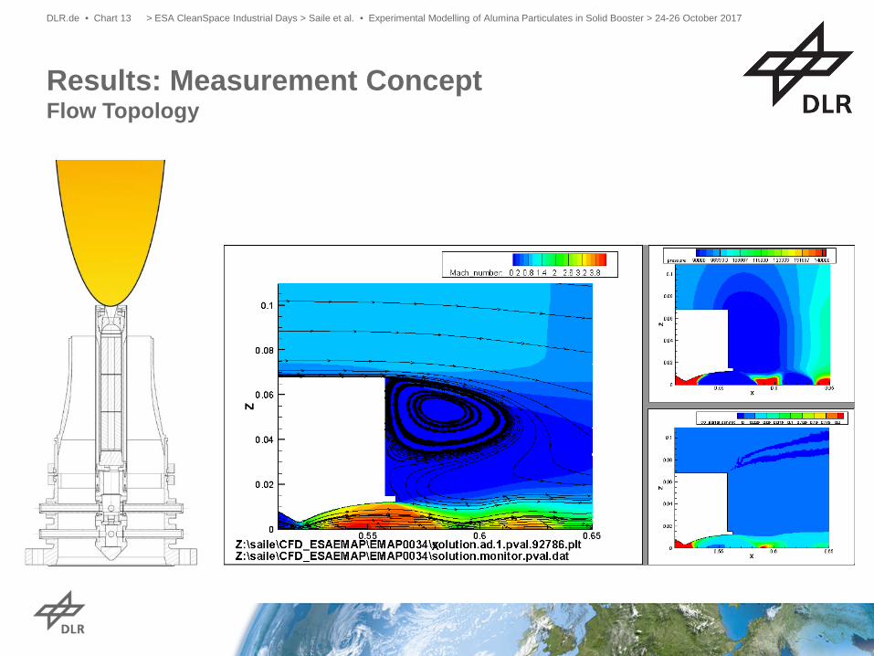
Results: Measurement Concept Flow Topology
> ESA CleanSpace Industrial Days > Saile et al. • Experimental Modelling of Alumina Particulates in Solid Booster > 24-26 October 2017 DLR.de • Chart 13
> ESA CleanSpace Industrial Days > Saile et al. • Experimental Modelling of Alumina Particulates in Solid Booster > 24-26 October 2017 DLR.de • Chart 14
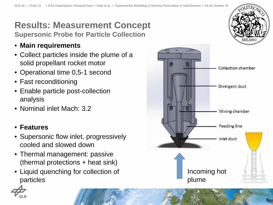
Results: Measurement Concept Supersonic Probe for Particle Collection
• Main requirements • Collect particles inside the plume of a
solid propellant rocket motor • Operational time 0,5-1 second • Fast reconditioning • Enable particle post-collection
analysis • Nominal inlet Mach: 3.2
• Features • Supersonic flow inlet, progressively
cooled and slowed down • Thermal management: passive
(thermal protections + heat sink) • Liquid quenching for collection of
particles Incoming hot plume
> ESA CleanSpace Industrial Days > Saile et al. • Experimental Modelling of Alumina Particulates in Solid Booster > 24-26 October 2017 DLR.de • Chart 15
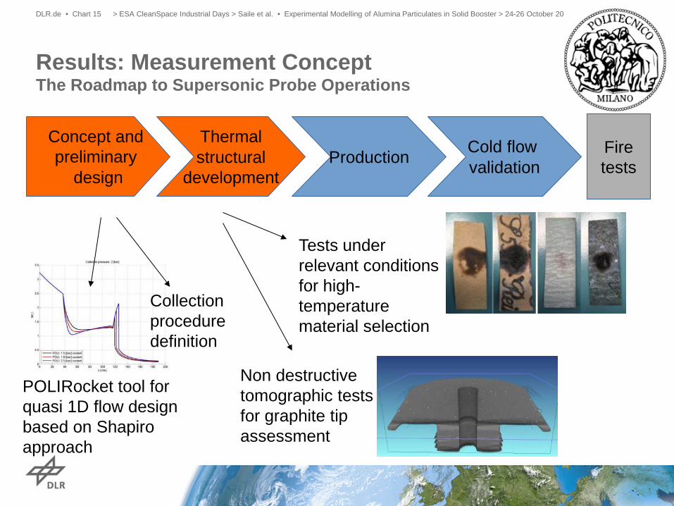
Results: Measurement Concept The Roadmap to Supersonic Probe Operations
Concept and preliminary
design
Thermal structural
development Production Cold flow
validation Fire tests
POLIRocket tool for quasi 1D flow design based on Shapiro approach
Non destructive tomographic tests for graphite tip assessment
Tests under relevant conditions for high-temperature material selection
Collection procedure definition
> ESA CleanSpace Industrial Days > Saile et al. • Experimental Modelling of Alumina Particulates in Solid Booster > 24-26 October 2017 DLR.de • Chart 16
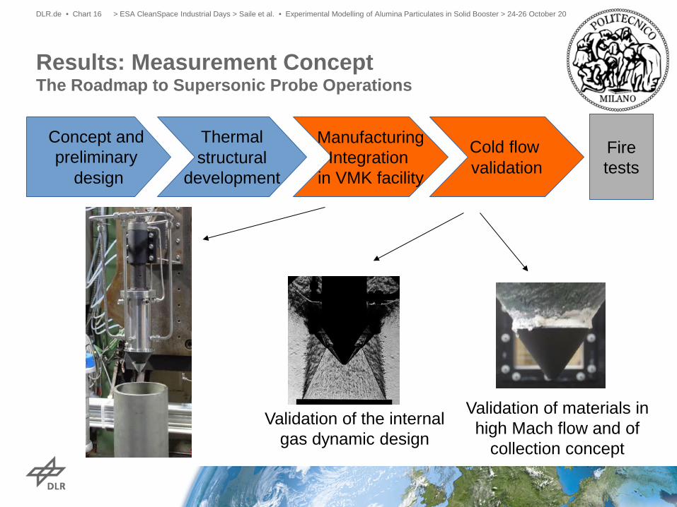
Validation of the internal gas dynamic design
Validation of materials in high Mach flow and of
collection concept
Concept and preliminary
design
Thermal structural
development
Manufacturing Integration
in VMK facility
Cold flow validation
Fire tests
Results: Measurement Concept The Roadmap to Supersonic Probe Operations
Results: Measurement Concept Plume Collection Probe Flow Simulation
> ESA CleanSpace Industrial Days > Saile et al. • Experimental Modelling of Alumina Particulates in Solid Booster > 24-26 October 2017 DLR.de • Chart 17
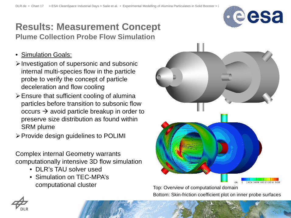
Top: Overview of computational domain Bottom: Skin-friction coefficient plot on inner probe surfaces
• Simulation Goals: Investigation of supersonic and subsonic
internal multi-species flow in the particle probe to verify the concept of particle deceleration and flow cooling Ensure that sufficient cooling of alumina
particles before transition to subsonic flow occurs avoid particle breakup in order to preserve size distribution as found within SRM plume Provide design guidelines to POLIMI Complex internal Geometry warrants computationally intensive 3D flow simulation
• DLR’s TAU solver used • Simulation on TEC-MPA’s
computational cluster
> ESA CleanSpace Industrial Days > Saile et al. • Experimental Modelling of Alumina Particulates in Solid Booster > 24-26 October 2017 DLR.de • Chart 18
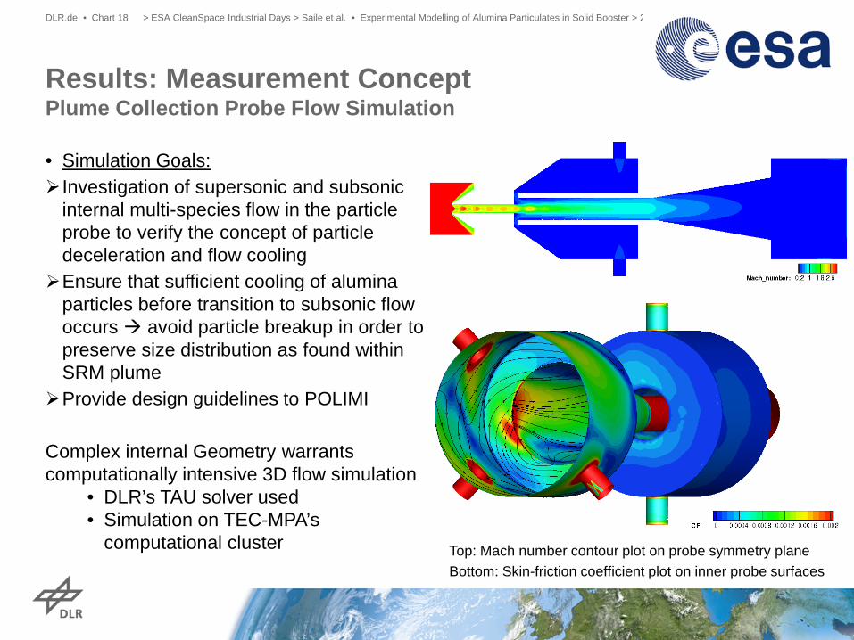
Top: Mach number contour plot on probe symmetry plane Bottom: Skin-friction coefficient plot on inner probe surfaces
• Simulation Goals: Investigation of supersonic and subsonic
internal multi-species flow in the particle probe to verify the concept of particle deceleration and flow cooling Ensure that sufficient cooling of alumina
particles before transition to subsonic flow occurs avoid particle breakup in order to preserve size distribution as found within SRM plume Provide design guidelines to POLIMI Complex internal Geometry warrants computationally intensive 3D flow simulation
• DLR’s TAU solver used • Simulation on TEC-MPA’s
computational cluster
Results: Measurement Concept Plume Collection Probe Flow Simulation
> ESA CleanSpace Industrial Days > Saile et al. • Experimental Modelling of Alumina Particulates in Solid Booster > 24-26 October 2017 DLR.de • Chart 19
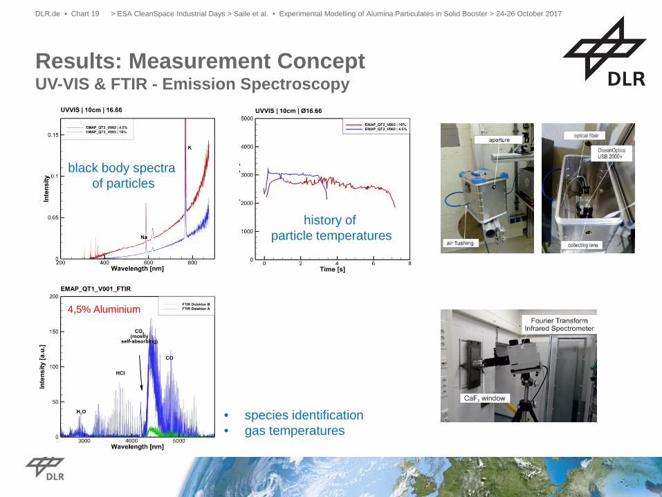
Results: Measurement Concept UV-VIS & FTIR - Emission Spectroscopy
4,5% Aluminium
black body spectra of particles
history of particle temperatures
• species identification • gas temperatures
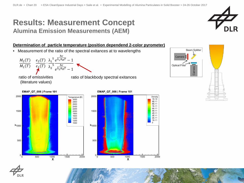
Determination of particle temperature (position dependend 2-color pyrometer) • Measurement of the ratio of the spectral exitances at to wavelengths
> ESA CleanSpace Industrial Days > Saile et al. • Experimental Modelling of Alumina Particulates in Solid Booster > 24-26 October 2017 DLR.de • Chart 20
Results: Measurement Concept Alumina Emission Measurements (AEM)
𝑀𝑀2 𝑇𝑇𝑀𝑀1 𝑇𝑇
=𝜖𝜖2 𝑇𝑇𝜖𝜖1 𝑇𝑇
∙λ1
5
λ25𝑒𝑒
ℎ𝑐𝑐λ1𝑘𝑘𝐵𝐵𝑇𝑇 − 1
𝑒𝑒ℎ𝑐𝑐
λ2𝑘𝑘𝐵𝐵𝑇𝑇 − 1
ratio of emissivities (literature values)
ratio of blackbody spectral exitances
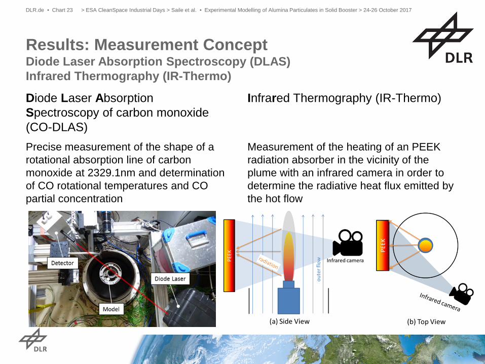
Diode Laser Absorption Spectroscopy of carbon monoxide (CO-DLAS)
Results: Measurement Concept Diode Laser Absorption Spectroscopy (DLAS) Infrared Thermography (IR-Thermo)
> ESA CleanSpace Industrial Days > Saile et al. • Experimental Modelling of Alumina Particulates in Solid Booster > 24-26 October 2017 DLR.de • Chart 23
Infrared Thermography (IR-Thermo)
Precise measurement of the shape of a rotational absorption line of carbon monoxide at 2329.1nm and determination of CO rotational temperatures and CO partial concentration
Measurement of the heating of an PEEK radiation absorber in the vicinity of the plume with an infrared camera in order to determine the radiative heat flux emitted by the hot flow
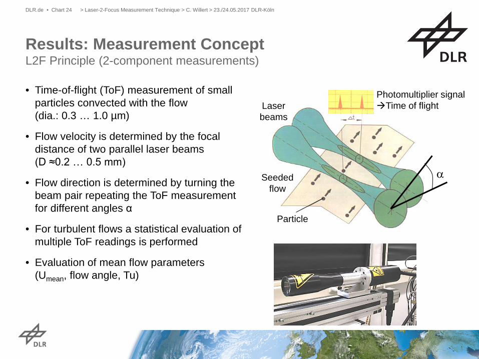
• Time-of-flight (ToF) measurement of small particles convected with the flow (dia.: 0.3 … 1.0 µm)
• Flow velocity is determined by the focal distance of two parallel laser beams (D ≈0.2 … 0.5 mm)
• Flow direction is determined by turning the beam pair repeating the ToF measurement for different angles α
• For turbulent flows a statistical evaluation of multiple ToF readings is performed
• Evaluation of mean flow parameters (Umean, flow angle, Tu)
Results: Measurement Concept L2F Principle (2-component measurements)
> Laser-2-Focus Measurement Technique > C. Willert > 23./24.05.2017 DLR-Köln DLR.de • Chart 24
Photomultiplier signal Time of flight Laser
beams
Seeded flow
Particle
α
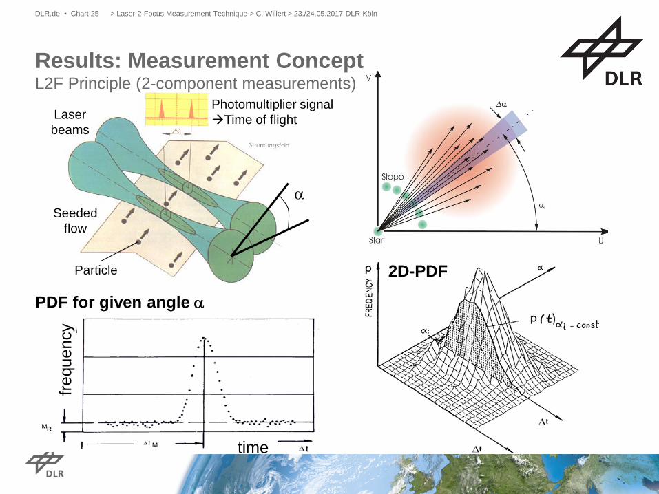
Photomultiplier signal Time of flight Laser
beams
Seeded flow
Particle
α
PDF for given angle α
time
frequ
ency
2D-PDF
> Laser-2-Focus Measurement Technique > C. Willert > 23./24.05.2017 DLR-Köln DLR.de • Chart 25
Results: Measurement Concept L2F Principle (2-component measurements)
> ESA-EMAP > D. Saile, L. Steffens, A. Gülhan • TN1 - Detailed Description of Measurement Techniques and Strategy > 19.11.2015 DLR.de • Folie 26
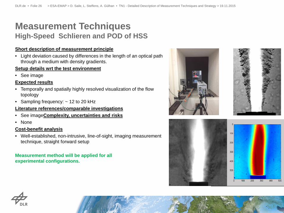
Measurement Techniques High-Speed Schlieren and POD of HSS Short description of measurement principle • Light deviation caused by differences in the length of an optical path
through a medium with density gradients. Setup details wrt the test environment • See image Expected results • Temporally and spatially highly resolved visualization of the flow
topology • Sampling frequency: ~ 12 to 20 kHz Literature references/comparable investigations • See imageComplexity, uncertainties and risks • None Cost-benefit analysis • Well-established, non-intrusive, line-of-sight, imaging measurement
technique, straight forward setup Measurement method will be applied for all experimental configurations.
> ESA-EMAP > D. Saile, L. Steffens, A. Gülhan • TN1 - Detailed Description of Measurement Techniques and Strategy > 19.11.2015 DLR.de • Folie 27
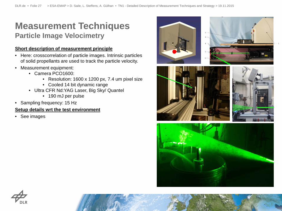
Measurement Techniques Particle Image Velocimetry Short description of measurement principle • Here: crosscorrelation of particle images. Intrinsic particles
of solid propellants are used to track the particle velocity. • Measurement equipment:
• Camera PCO1600: • Resolution: 1600 x 1200 px, 7.4 um pixel size • Cooled 14 bit dynamic range
• Ultra CFR Nd:YAG Laser, Big Sky/ Quantel • 190 mJ per pulse
• Sampling frequency: 15 Hz Setup details wrt the test environment • See images
> ESA-EMAP > D. Saile, L. Steffens, A. Gülhan • TN1 - Detailed Description of Measurement Techniques and Strategy > 19.11.2015 DLR.de • Folie 28
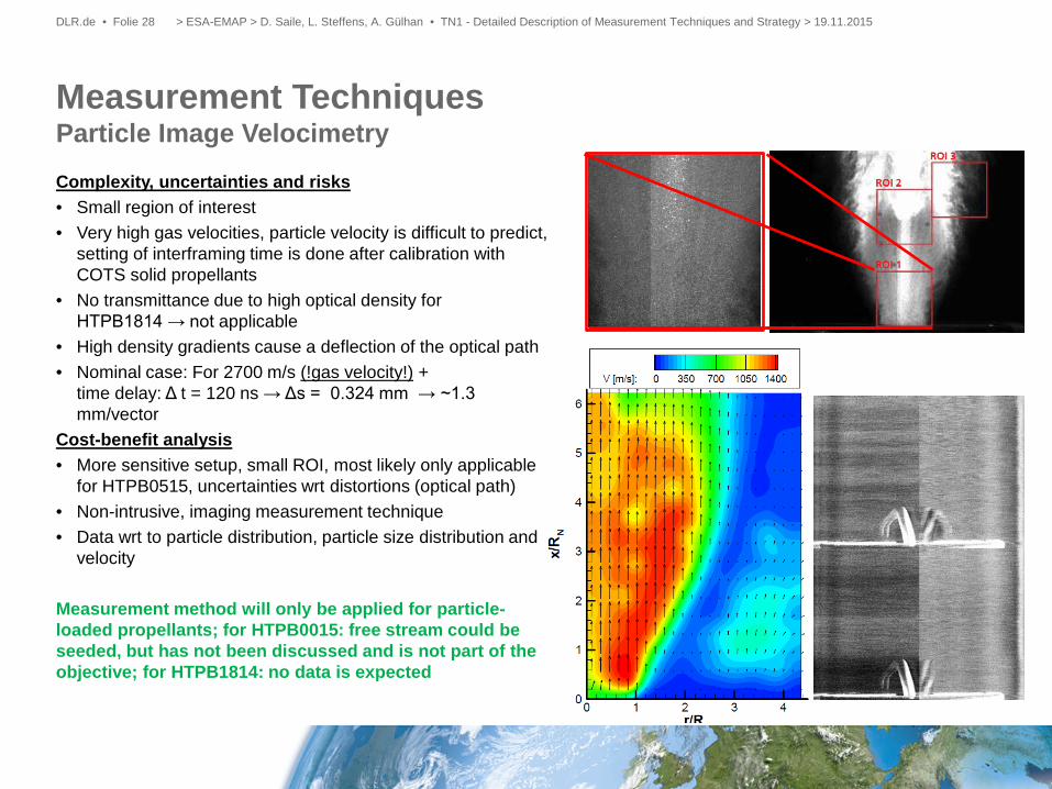
Measurement Techniques Particle Image Velocimetry Complexity, uncertainties and risks • Small region of interest • Very high gas velocities, particle velocity is difficult to predict,
setting of interframing time is done after calibration with COTS solid propellants
• No transmittance due to high optical density for HTPB1814 → not applicable
• High density gradients cause a deflection of the optical path • Nominal case: For 2700 m/s (!gas velocity!) +
time delay: Δ t = 120 ns → Δs = 0.324 mm → ~1.3 mm/vector
Cost-benefit analysis • More sensitive setup, small ROI, most likely only applicable
for HTPB0515, uncertainties wrt distortions (optical path) • Non-intrusive, imaging measurement technique • Data wrt to particle distribution, particle size distribution and
velocity
Measurement method will only be applied for particle-loaded propellants; for HTPB0015: free stream could be seeded, but has not been discussed and is not part of the objective; for HTPB1814: no data is expected
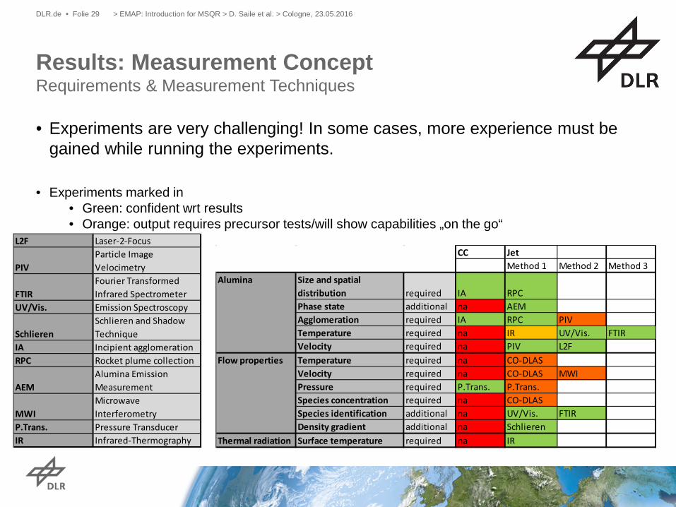
CC JetMethod 1 Method 2 Method 3
Size and spatial distribution required IA RPCPhase state additional na AEMAgglomeration required IA RPC PIVTemperature required na IR UV/Vis. FTIRVelocity required na PIV L2FTemperature required na CO-DLASVelocity required na CO-DLAS MWIPressure required P.Trans. P.Trans.Species concentration required na CO-DLASSpecies identification additional na UV/Vis. FTIRDensity gradient additional na Schlieren
Thermal radiation Surface temperature required na IR
Alumina
Flow properties
> EMAP: Introduction for MSQR > D. Saile et al. > Cologne, 23.05.2016 DLR.de • Folie 29
• Experiments are very challenging! In some cases, more experience must be gained while running the experiments.
• Experiments marked in • Green: confident wrt results • Orange: output requires precursor tests/will show capabilities „on the go“
L2F Laser-2-Focus
PIVParticle Image Velocimetry
FTIRFourier Transformed Infrared Spectrometer
UV/Vis. Emission Spectroscopy
SchlierenSchlieren and Shadow Technique
IA Incipient agglomerationRPC Rocket plume collection
AEMAlumina Emission Measurement
MWIMicrowave Interferometry
P.Trans. Pressure TransducerIR Infrared-Thermography
Results: Measurement Concept Requirements & Measurement Techniques
• Test environment was selected. • Wind tunnel model has been developed. • CFD data has been generated regarding an approximation of the wake flow
and • Numerous measurement techniques have been
• considered, • selected and • tested/qualified in validation tests for hot gas tests.
• Numerical data has been generated to validate the design of the rocket plume collector.
• Tests will start end of January 2017
Conclusion
> ESA CleanSpace Industrial Days > Saile et al. • Experimental Modelling of Alumina Particulates in Solid Booster > 24-26 October 2017 DLR.de • Chart 30
> ESA CleanSpace Industrial Days > Saile et al. • Experimental Modelling of Alumina Particulates in Solid Booster > 24-26 October 2017 DLR.de • Chart 31
End
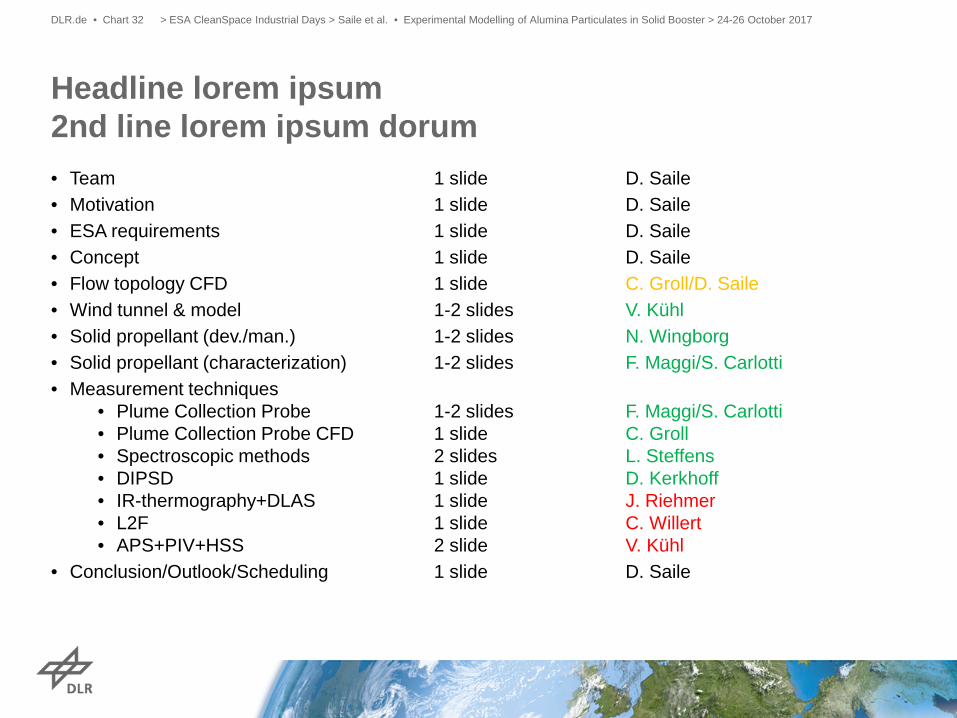
• Team 1 slide D. Saile • Motivation 1 slide D. Saile • ESA requirements 1 slide D. Saile • Concept 1 slide D. Saile • Flow topology CFD 1 slide C. Groll/D. Saile • Wind tunnel & model 1-2 slides V. Kühl • Solid propellant (dev./man.) 1-2 slides N. Wingborg • Solid propellant (characterization) 1-2 slides F. Maggi/S. Carlotti • Measurement techniques
• Plume Collection Probe 1-2 slides F. Maggi/S. Carlotti • Plume Collection Probe CFD 1 slide C. Groll • Spectroscopic methods 2 slides L. Steffens • DIPSD 1 slide D. Kerkhoff • IR-thermography+DLAS 1 slide J. Riehmer • L2F 1 slide C. Willert • APS+PIV+HSS 2 slide V. Kühl
• Conclusion/Outlook/Scheduling 1 slide D. Saile
Headline lorem ipsum 2nd line lorem ipsum dorum
> ESA CleanSpace Industrial Days > Saile et al. • Experimental Modelling of Alumina Particulates in Solid Booster > 24-26 October 2017 DLR.de • Chart 32