Embed Size (px)
Citation preview

EXPERIMENTAL INVESTIGATION OF THE FLOW-INDUCED VIBRATION OF ACURVED CIRCULAR CYLINDER
Gustavo R.S. Assi∗
University of Sao Paulo, BrazilDept. Naval Arch. & Ocean Eng. – NDF Group
Cesar M. FreireUniversity of Sao Paulo, Brazil
Dept. Mechanical Eng. – NDF Group
Ivan KorkischkoUniversity of Sao Paulo, Brazil
Dept. Mechanical Eng. – NDF Group
Narakorn SrinilUniversity of Strathclyde, Glasgow, UKDept. Naval Arch. & Marine Eng.
ABSTRACTExperiments have been conducted in a water channel
in order to investigate the vortex-induced vibration (VIV)response of a rigid section of a curved circular cylinder.Two curved configurations were tested regarding the di-rection of the approaching flow, a concave or a convexcylinder, in addition to a straight cylinder that served asreference.
Amplitude and frequency response are presented ver-sus reduced velocity for a wide Reynolds number rangebetween 750 and 15,000. Results showed that the curvedcylinders presented significant less vibration for both con-cave and convex configurations when compared to thetypical VIV response of a straight cylinder.
The concave configuration presented relatively highamplitudes of vibration that are sustained beyond the typ-ical synchronisation region. We believe this distinct be-haviour between the convex and the concave configura-tions is related to the wake interference happening in thelower half of the curvature due to perturbations generatedin the horizontal section when it is positioned upstream.
Particle-image velocimetry (PIV) measurements ofthe separated flow along the cylinder highlight the effectof curvature on vortex formation and excitation reveal-ing an interesting and complex fluid-structure interactionmechanism.
∗Corresponding author: [email protected]. Address: PNV Dept. Eng.Naval e Oceanica, Escola Politecnica da Universidade de Sao Paulo,Av. Prof Mello Moraes 2231, 05508-030, Sao Paulo - SP, Brazil.www.ndf.poli.usp.br.
NOMENCLATURED Cylinder external diameterh Cylinder vertical length below the water linem∗ Mass ratioζ Structural damping ratiof0 Cross-flow natural frequency in airU Flow speedU/D f0 Reduced velocityx Streamwise harmonic amplitude of vibrationy Cross-flow harmonic amplitude of vibrationfx Streamwise oscillating frequencyfy Cross-flow oscillating frequencyRe Reynolds numberSt Strouhal number
INTRODUCTIONOngoing deep-sea explorations, installations and pro-
ductions of hydrocarbon energy need the development ofnew viable technologies. One of these is the requirementof a robust and completely-reliable analysis tool for theprediction of vortex-induced vibration (VIV) of marinestructures exposed to ocean currents. Because VIV cancause high cyclic-loading fatigue damage of structures, itis now widely accepted that VIV is a crucial factor thatshould be taken into account in the preliminary analysisand design. However, many insightful VIV aspects arestill unknown and far from fully understood; these renderthe structural design quite conservative with the use of alarge factor of safety. For offshore structures with ini-tial curvatures and high flexibility such as catenary risers,

mooring cables and free-spanning pipelines, the theoreti-cal, numerical or experimental VIV research is still verylacking.
Risers are very long pipes used to carry oil fromthe sea bed to offshore platforms floating on the watersurface. Under the effect of sea currents, these flexi-ble structures are especially susceptible to flow-inducedvibrations, particularly since they have a relatively lowmass compared to the mass of the displaced fluid. Gen-erally, an offshore floating platform accommodates morethan 40 riser pipes together with many other cylindricalstructures. The interaction of these flexible structures canproduce an even more complex problem, resulting in vi-brations with rather unexpectedly higher amplitudes [1].Flow interference from the platform hull, the soil on seabed and the pipe itself can also increase the complexity ofthe flow, generating complex responses.
The riser may respond with different amplitudes andfrequencies depending on the flow excitation and struc-tural stiffness along the length of the pipe. Consequently,several modes of vibration with varying curvature appearalong the span resulting in a very rich fluid-structure inter-action mechanism [2]. In addition to that, flexible riserscan be laid out in a catenary configuration which resultsin high curvature close to the region where it touches thebottom of the ocean, called the touchdown point.
In an attempt to understand and model the fluid-dynamic behaviour around curved sections of risers wehave performed experiments with a curved section ofrigid cylinder in a water channel. This idealised exper-iment is far from reproducing the real conditions encoun-tered in the ocean, nevertheless it should throw some lighton understanding how the vortex shedding mechanism isaffected by the curvature of the pipe.
An investigation into the vortex shedding patterns andthe fundamental wake topology of the flow past a station-ary curved circular cylinder has been carried out by Mil-iou et al. [3] based on the computational fluid dynamicsstudies. As a result of pipe initial curvatures, the flow vi-sualizations highlight different kinds of wake characteris-tics depending on the pipe (convex or concave) configu-ration and its orientation with respect to (aligned with ornormal to) the incoming flow. When the flow is uniformand normal to the curvature plane, the cross-flow wakedynamics of curved pipes behave qualitatively similar tothose of straight pipes. This is in contrast to the case offlow being aligned with the curvature plane where wakedynamics change dramatically. However, these scenariosare pertinent to a particular stationary cylinder case in avery low-Reynolds number range. The VIV behaviourswill further transform if the structure oscillates and in-
teracts with the fluid wakes, depending on several fluid-structure parameters.
EXPERIMENTAL ARRANGEMENTExperiments have been carried out in the Circulat-
ing Water Channel of the NDF (Fluids and Dynamics Re-search Group) at the University of Sao Paulo, Brazil. TheNDF-USP water channel has an open test section 0.7mwide, 0.9m deep and 7.5m long. Good quality flow canbe achieved up to 1.0m/s with turbulence intensity lessthan 3%. This laboratory has been especially designedfor experiments in flow-induced vibrations and more de-tails about the facilities are described in Assi et al. [4].
A rigid section of a curved circular cylinder, with anexternal diameter of D = 32mm, was made of ABS plas-tic and Perspex tubes according to the dimensions shownin Figure 1. The curved cylinder was composed of a hor-izontal section with 10D in length, a curved section witha 10D radius and a vertical section with length h/D thatcould be varied with reference to the water line. The wa-ter level was set to 700mm from the floor of the chan-nel, which means that the 10D-long horizontal part of thecylinder was not close enough to the floor to suffer inter-ference from the wall.
The model was connected by its upper end to a longpendulum rig (length H = 3.0m) that allowed the systemto oscillate in two degrees of freedom (2dof) in the cross-flow and streamwise directions. The model was attachedto two pairs of coil springs that provided the stiffness ofthe system. The springs were set to provide the same nat-ural frequency ( f0) in both the cross-flow and streamwisedirections. The design and construction of the pendularelastic rig was made by Freire et al. [5] based on a pre-vious idea employed by Assi et al. [6, 7] for experimentswith VIV suppressors. The present apparatus has beenvalidated for VIV experiments by Freire at al. [8, 9].
Two laser sensors measured the cross-flow andstreamwise displacements of the pendulum referring tothe displacement of the bottom tip of the models. An es-pecially built load cell was installed between the cylinderand the pendulum arm to allow for instantaneous mea-surements of lift, drag and torque acting on the cylinder.(Hydrodynamic forces will not be discussed in this pa-per.) A particle-image velocimetry (PIV) system was em-ployed to analyse the wake along the span.
Regarding the flow direction, two orientations wereinvestigated: a convex and a concave configuration ac-cording to the direction of the flow approaching the cur-vature. The flow direction in the test section of the waterchannel was not changed; naturally the curved cylinder

FIGURE 1: Experimental arrangement in the NDF-USP circulating water channel. The flow directon could not bechanged in the water channel; in practice, the cylinder was rotated to arrange concave and convex configurations.
TABLE 1: Structural properties.
m∗ ζ m∗ζ
Straight cylinder 2.8 0.2% 0.0056
Curved cylinders 2.1 0.2% 0.0042
was rotated to allow for both concave and convex arrange-ments. This is also illustrated in Figure 1.
Decay tests have been performed in air in order todetermine the natural frequencies of the system in bothdirections as well as the level of structural damping. Theapparatus with one universal joint and four springs turnedout to present a very low structural damping of ζ = 0.2%,measured as a fraction of the critical damping. The to-tal oscillating mass of the system was measured in air,resulting in a non-dimensional mass ratio m∗, defined asthe ratio between the total mass and the mass of displacedfluid. Consequently, the mass-damping parameter m∗ζ ofthe system was kept to the lowest possible value in orderto amplify the amplitude of response.
Table 1 presents a summary of the structural parame-ter for both the straight and curved cylinder.
RESULTS OF A STRAIGHT CYLINDER
A preliminary VIV experiment was performed witha straight cylinder in order to validate the set-up andmethodology. The same pendulum rig was employed,only replacing the curved model by a straight cylinderwith the same diameter. This time, the straight cylinderwas long enough to reach the bottom wall only leaving a3mm clearance to allow for free movement of the pendu-lum in any direction.
The dynamic response of the straight cylinder cov-ered a reduced velocity range from 1.5 to 12, where re-duced velocity (U/D f0) is defined using the cylinder nat-ural frequency of oscillation measured in air. The onlyflow variable changed during the course of the experi-ments was the flow velocity U , which, as for full-scalerisers, alters both the reduced velocity and the Reynoldsnumber between 750 and 15,000 for a maximum reducedvelocity of 20.
Throughout the study, cylinder displacement ampli-tudes (x/D for the streamwise and y/D for the cross-flowdirections) were found by measuring the root mean squarevalue of response and multiplying by the square root of 2(the so called harmonic amplitude). This is likely to givean underestimation of maximum response but was judgedto be perfectly acceptable for assessing the general be-

0
0.2
0.4
0.6
0.8
1
1.2
1.4
1.6
1.8
y/D
0 2 4 6 8 10 12 14 16 18 200
0.1
0.2
0.3
0.4
0.5
0.6
0.7
0.8
0.9
U/Df0
x/D
Straight cylinder
Concave: h/D = 0
Concave: h/D = 5
Concave: h/D = 10
FIGURE 2: Cross-flow (y/D) and streamwise (x/D) amplitude of vibration versus reduced velocity for a straight cylinderand concave configurations varying the vertical section length (h/D).
0
0.5
1
1.5
2
2.5
3
3.5
4
f y/f 0
0 2 4 6 8 10 12 14 16 18 200
0.5
1
1.5
2
2.5
3
3.5
4
U/Df0
f x/f 0
Straight cylinder
Concave: h/D = 0
Concave: h/D = 5
Concave: h/D = 10
FIGURE 3: Cross-flow (y/D) and streamwise (x/D) dominant frequency of response versus reduced velocity for a straightcylinder and curved concave configurations varying the vertical section length (h/D).

0
0.2
0.4
0.6
0.8
1
1.2
1.4
1.6
1.8
y/D
0 2 4 6 8 10 12 14 16 18 200
0.1
0.2
0.3
0.4
0.5
0.6
0.7
0.8
0.9
U/Df0
x/D
Straight cylinder
Convex: h/D = 0
Convex: h/D = 5
Convex: h/D = 10
FIGURE 4: Cross-flow (y/D) and streamwise (x/D) amplitude of vibration versus reduced velocity for a straight cylinderand convex configurations varying the vertical section length (h/D).
0
0.5
1
1.5
2
2.5
3
3.5
4
f y/f 0
0 2 4 6 8 10 12 14 16 18 200
0.5
1
1.5
2
2.5
3
3.5
4
U/Df0
f x/f 0
Straight cylinder
Convex: h/D = 0
Convex: h/D = 5
Convex: h/D = 10
FIGURE 5: Cross-flow (y/D) and streamwise (x/D) dominant frequency of response versus reduced velocity for a straightcylinder and curved convex configurations varying the vertical section length (h/D).

haviour of VIV, since the response is mostly harmonic.Results presented in the present study correspond to thedisplacement of the lowest point of the model, i.e., the endof the cylinder closer to the section floor, thus represent-ing the maximum displacement developed by each model.Displacements are non-dimensionalised by the cylinderdiameter D.
Figures 2 and 4 compare the reference cross-flow andstreamwise responses obtained from two different runswith the straight cylinder. In the first one, flow speed wasincreased in 30 steps from zero to a maximum, while inthe second it was decreased from the maximum to zero.Both data sets overlap rather well for all the reduced ve-locity range except for a region around U/D f0 = 6 wherethe well-known phenomenon of hysteresis in the VIV re-sponse has been observed. The streamwise VIV responsealso seems to occur in two resonance ranges (U/D f0 = 2and 6), the so-called second and third instability rangesinvolving asymmetric vortices.
Although the observed peak amplitude of y/D = 1.5around U/D f0 = 6 is slightly higher than other resultsfound in the literature for similar values of m∗ (for exam-ple, Assi et al. [6]) the general behaviour of both curvesshow a typical response for 2-dof VIV. The higher am-plitude found here could be explained by the very lowmass-damping characteristics of the system and the geo-metric projection of the amplitude at the tip of the modeland not at mid-length as usual.
Although the cylinder was initially aligned in the ver-tical position, in flowing water the mean drag displacesthe cylinder from its original location reaching a slightlyinclined configuration from the vertical. This was judgednot to be detrimental to the experiment; hence the inclina-tion of the cylinder was not corrected between each step.The same procedure was adopted for the curved cylinder.
Figures 3 and 5 present the dominant frequency ofresponse versus reduced velocity. The dataset for thestraight cylinder is repeated in both figures to serve asreference. Two dashed lines inclined with different slopesrepresent the region for a Strouhal number of 0.2 and 0.4,i.e., an estimation of the vortex shedding frequency fora straight cylinder in the cross-flow and streamwise di-rection respectively. It is clear that the straight cylinderpresents a typical VIV response oscillating in the cross-flow direction with a frequency following the St = 0.2line up to the beginning of the upper branch. Eventually,fy/ f0 departs from St = 0.2 towards the unity value. Thebehaviour observed for the streamwise vibration is alsotypical of VIV with the difference that the frequency ofresponse is twice as that for the cross-flow direction dur-ing much of the synchronisation range.
RESPONSE OF THE CURVED CYLINDERSAs mentioned above, experiments with the curved
cylinder were performed taking into account two dis-tinct configurations as far as the flow direction is con-cerned. In the concave configuration the flow approachesthe model reaching first the horizontal section. As op-posed to that, in the convex configuration the horizontalsection is placed downstream of the curved and verticalparts.
Amplitude of vibrationIn general terms, as presented in Figures 2 and 4,
the curved cylinders showed significantly less vibrationfor both concave and convex configurations when com-pared to the typical VIV response of the straight cylinder.Such a reduction is noticeable in both the cross-flow andstreamwise responses. This clearly shows that the curva-ture of the cylinder modifies the vortex shedding mech-anism in a manner that the structure extracts less energyfrom the flow. We shall return to this point when investi-gating the velocity flow field with PIV.
For each concave and convex configuration, the ver-tical section of the cylinder close to the free surface wasvaried in three different lengths: h/D = 0, 5 and 10. Theoverall response for the three values of h/D is very sim-ilar, showing only minor differences at the beginning ofthe synchronisation range between U/D f0 = 3.0 and 5.0.Apart from that, no distinct behaviour was observed as faras a variation in h/D is concerned for both concave andconvex configurations.
The cross-flow displacement does not reveal distinctupper and lower branches of vibration such as those ob-served for a straight cylinder, but it produces a smoothcurve that spans the whole synchronisation region withmaximum amplitude around y/D = 0.75 for the concaveand 0.65 for the convex configurations. No hysteresis isfound.
However, the most interesting feature of such a be-haviour is found when the convex response is comparedwith the concave one (Figures 2 and 4). While the convexcurve for y/D drops immediately between U/D f0 = 8 and10 to a level of y/D ≈ 0.1, the response for the concavecase does not diminish, but is sustained for higher reducedvelocities around y/D = 0.3 until the end of the experi-ment. Apparently there must be a fluidelastic mechanismoccurring for reduced velocities above 8.0 for the concaveconfiguration capable of extracting energy from the flowto sustain vibrations around y/D = 0.3. We shall discussthis point later while analysing the PIV flow fields.
In the streamwise direction the responses of thecurved cylinders are different from the typical VIV de-
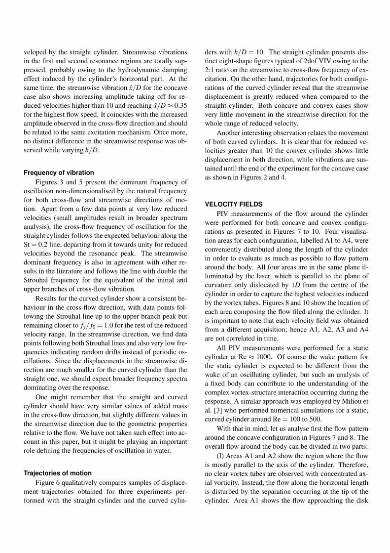
veloped by the straight cylinder. Streamwise vibrationsin the first and second resonance regions are totally sup-pressed, probably owing to the hydrodynamic dampingeffect induced by the cylinder’s horizontal part. At thesame time, the streamwise vibration x/D for the concavecase also shows increasing amplitude taking off for re-duced velocities higher than 10 and reaching x/D ≈ 0.35for the highest flow speed. It coincides with the increasedamplitude observed in the cross-flow direction and shouldbe related to the same excitation mechanism. Once more,no distinct difference in the streamwise response was ob-served while varying h/D.
Frequency of vibrationFigures 3 and 5 present the dominant frequency of
oscillation non-dimensionalised by the natural frequencyfor both cross-flow and streamwise directions of mo-tion. Apart from a few data points at very low reducedvelocities (small amplitudes result in broader spectrumanalysis), the cross-flow frequency of oscillation for thestraight cylinder follows the expected behaviour along theSt = 0.2 line, departing from it towards unity for reducedvelocities beyond the resonance peak. The streamwisedominant frequency is also in agreement with other re-sults in the literature and follows the line with double theStrouhal frequency for the equivalent of the initial andupper branches of cross-flow vibration.
Results for the curved cylinder show a consistent be-haviour in the cross-flow direction, with data points fol-lowing the Strouhal line up to the upper branch peak butremaining closer to fy/ f0 = 1.0 for the rest of the reducedvelocity range. In the streamwise direction, we find datapoints following both Strouhal lines and also very low fre-quencies indicating random drifts instead of periodic os-cillations. Since the displacements in the streamwise di-rection are much smaller for the curved cylinder than thestraight one, we should expect broader frequency spectradominating over the response.
One might remember that the straight and curvedcylinder should have very similar values of added massin the cross-flow direction, but slightly different values inthe streamwise direction due to the geometric propertiesrelative to the flow. We have not taken such effect into ac-count in this paper, but it might be playing an importantrole defining the frequencies of oscillation in water.
Trajectories of motionFigure 6 qualitatively compares samples of displace-
ment trajectories obtained for three experiments per-formed with the straight cylinder and the curved cylin-
ders with h/D = 10. The straight cylinder presents dis-tinct eight-shape figures typical of 2dof VIV owing to the2:1 ratio on the streamwise to cross-flow frequency of ex-citation. On the other hand, trajectories for both configu-rations of the curved cylinder reveal that the streamwisedisplacement is greatly reduced when compared to thestraight cylinder. Both concave and convex cases showvery little movement in the streamwise direction for thewhole range of reduced velocity.
Another interesting observation relates the movementof both curved cylinders. It is clear that for reduced ve-locities greater than 10 the convex cylinder shows littledisplacement in both direction, while vibrations are sus-tained until the end of the experiment for the concave caseas shown in Figures 2 and 4.
VELOCITY FIELDSPIV measurements of the flow around the cylinder
were performed for both concave and convex configu-rations as presented in Figures 7 to 10. Four visualisa-tion areas for each configuration, labelled A1 to A4, wereconveniently distributed along the length of the cylinderin order to evaluate as much as possible to flow patternaround the body. All four areas are in the same plane il-luminated by the laser, which is parallel to the plane ofcurvature only dislocated by 1D from the centre of thecylinder in order to capture the highest velocities inducedby the vortex tubes. Figures 8 and 10 show the location ofeach area composing the flow filed along the cylinder. Itis important to note that each velocity field was obtainedfrom a different acquisition; hence A1, A2, A3 and A4are not correlated in time.
All PIV measurements were performed for a staticcylinder at Re ≈ 1000. Of course the wake pattern forthe static cylinder is expected to be different from thewake of an oscillating cylinder, but such an analysis ofa fixed body can contribute to the understanding of thecomplex vortex-structure interaction occurring during theresponse. A similar approach was employed by Miliou etal. [3] who performed numerical simulations for a static,curved cylinder around Re = 100 to 500.
With that in mind, let us analyse first the flow patternaround the concave configuration in Figures 7 and 8. Theoverall flow around the body can be divided in two parts:
(I) Areas A1 and A2 show the region where the flowis mostly parallel to the axis of the cylinder. Therefore,no clear vortex tubes are observed with concentrated ax-ial vorticity. Instead, the flow along the horizontal lengthis disturbed by the separation occurring at the tip of thecylinder. Area A1 shows the flow approaching the disk

0 2 4 6 8 10 12 14 16 18 20
−1
0
1
U/Df0y/
D(a) Straight cylinder
0 2 4 6 8 10 12 14 16 18 20
−1
0
1
U/Df0
y/D
(b) Curved cylinder, concave configuraion, h/D = 10.
0 2 4 6 8 10 12 14 16 18 20
−1
0
1
U/Df0
y/D
(c) Curved cylinder, convex configuration, h/D = 10.
FIGURE 6: Response trajectories of motion for a (a) straight cylinder and a curved cylinder in (b) concave and (c) convexconfigurations.
facing upstream and separating into a recirculation bub-ble. The periodicity of the shedding associated with thisregion is also related to the flow speed and the diameterD, but no coherent vortices parallel to the cylinder is ableto form. As a consequence, a cascade of small vorticesis convected downstream along the horizontal length (seearea A2) reaching the beginning of the curved section.
(II) Areas A3 and A4 show the region where the flowis mainly perpendicular to the axis of the cylinder. Co-herent vortex tubes tend to form following the curvatureof the body, but further downstream they are stretchedand rapidly breakdown into smaller vortices that are con-vected by the flow. Area A3 show the instant when a vor-tex tube is shed almost tangent to the curvature, while areaA4, around the vertical section, reveal a formation regionmore or less aligned with the axis of the cylinder. Stream-lines drawn in areas A3 and A4 reveal a non-negligiblevelocity component deflecting the flow downwards im-mediately after the vortex formation region. As we movealong the cylinder towards the water line from A3 to A4the downward component is gradually reduced until iteventually disappears towards the upper half of A4. Thisregion marks the competition between two wake modesexistent along the transition from curved to straight cylin-der. This looks similar to Fig. 15 in Miliou et al. [3], withRe = 100, although without the cylinder horizontal sec-
tion therein.Analysing the flow pattern for the convex configura-
tion in Figures 9 and 10 we notice two striking differ-ences:
(I) Because the flow approaching the convex bodydoes not encounter a blunt disk facing upstream, no strongseparation or recirculation bubble is formed. As a conse-quence, the horizontal section seen in areas A1 and A2is not exposed to a disturbed, unsteady flow parallel tothe axis of the cylinder. In fact, A1 and A2 reveal thatthe upper half of the horizontal length is exposed to a pe-riodic flow formed by a regular wake, while the bottomhalf experiences almost no perturbation, with streamlinesshowing a well behaved flow field parallel to the axis.
(II) Now, looking at the upper half of the body (A3and A4) we notice much stronger and coherent vortextubes when compared to the flow around the concave con-figuration. Area A3 reveals some kind of vortex disloca-tion after a formation region that increases in length aswe move upwards. Because the convex geometry doesnot encourage the vortex tubes to stretch and break, a pe-riodic wake seems to be sustained farther downstream. Incontrast with the flow around the concave configuration,the velocity field around the curved section has a non-negligible vertical component upwards. It is stronger inA2 and is gradually reduced as we move upwards along

FIGURE 7: Composition of PIV velocity fields for concave configuration with h/D = 5.
CONCAVE: A1
(a) A1
CONCAVE: A2
(b) A2
CONCAVE: A3
(c) A3
CONCAVE: A4
(d) A4
FIGURE 8: Detailed velocity fields from Figure 7. Flow direction is from right to left and vectors are coloured by velocitymagnitude. Re = 1000.

FIGURE 9: Composition of PIV velocity fields for convex configuration with h/D = 5.
CONVEX: A1
(a) A1
CONVEX: A2
(b) A2
CONVEX: A3
(c) A3
CONVEX: A4
(d) A4
FIGURE 10: Detailed velocity fields from Figure 9. Flow direction is from right to left and vectors are coloured byvelocity magnitude. Re = 1000.
the curvature in A3. This looks similar to Fig. 3 in Miliouet al. [3] for Re = 100.
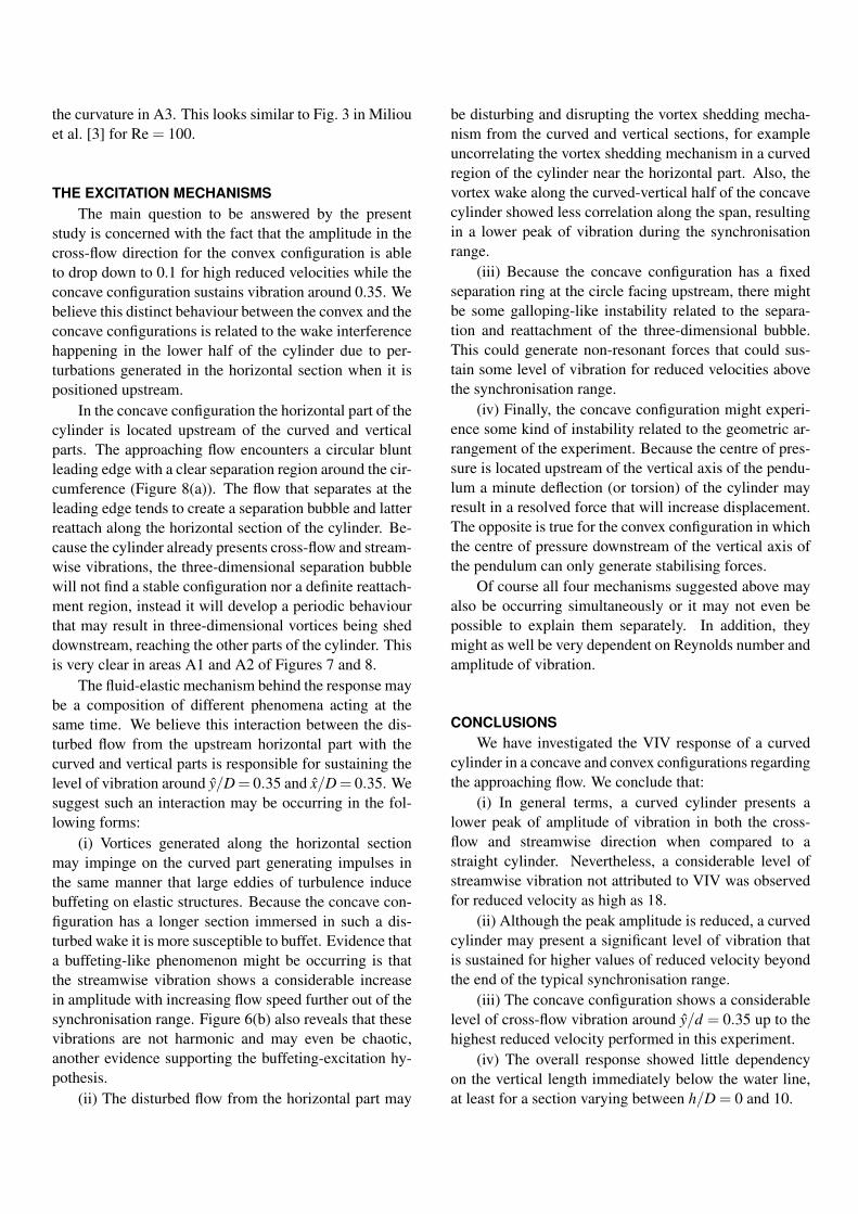
THE EXCITATION MECHANISMSThe main question to be answered by the present
study is concerned with the fact that the amplitude in thecross-flow direction for the convex configuration is ableto drop down to 0.1 for high reduced velocities while theconcave configuration sustains vibration around 0.35. Webelieve this distinct behaviour between the convex and theconcave configurations is related to the wake interferencehappening in the lower half of the cylinder due to per-turbations generated in the horizontal section when it ispositioned upstream.
In the concave configuration the horizontal part of thecylinder is located upstream of the curved and verticalparts. The approaching flow encounters a circular bluntleading edge with a clear separation region around the cir-cumference (Figure 8(a)). The flow that separates at theleading edge tends to create a separation bubble and latterreattach along the horizontal section of the cylinder. Be-cause the cylinder already presents cross-flow and stream-wise vibrations, the three-dimensional separation bubblewill not find a stable configuration nor a definite reattach-ment region, instead it will develop a periodic behaviourthat may result in three-dimensional vortices being sheddownstream, reaching the other parts of the cylinder. Thisis very clear in areas A1 and A2 of Figures 7 and 8.
The fluid-elastic mechanism behind the response maybe a composition of different phenomena acting at thesame time. We believe this interaction between the dis-turbed flow from the upstream horizontal part with thecurved and vertical parts is responsible for sustaining thelevel of vibration around y/D= 0.35 and x/D= 0.35. Wesuggest such an interaction may be occurring in the fol-lowing forms:
(i) Vortices generated along the horizontal sectionmay impinge on the curved part generating impulses inthe same manner that large eddies of turbulence inducebuffeting on elastic structures. Because the concave con-figuration has a longer section immersed in such a dis-turbed wake it is more susceptible to buffet. Evidence thata buffeting-like phenomenon might be occurring is thatthe streamwise vibration shows a considerable increasein amplitude with increasing flow speed further out of thesynchronisation range. Figure 6(b) also reveals that thesevibrations are not harmonic and may even be chaotic,another evidence supporting the buffeting-excitation hy-pothesis.
(ii) The disturbed flow from the horizontal part may
be disturbing and disrupting the vortex shedding mecha-nism from the curved and vertical sections, for exampleuncorrelating the vortex shedding mechanism in a curvedregion of the cylinder near the horizontal part. Also, thevortex wake along the curved-vertical half of the concavecylinder showed less correlation along the span, resultingin a lower peak of vibration during the synchronisationrange.
(iii) Because the concave configuration has a fixedseparation ring at the circle facing upstream, there mightbe some galloping-like instability related to the separa-tion and reattachment of the three-dimensional bubble.This could generate non-resonant forces that could sus-tain some level of vibration for reduced velocities abovethe synchronisation range.
(iv) Finally, the concave configuration might experi-ence some kind of instability related to the geometric ar-rangement of the experiment. Because the centre of pres-sure is located upstream of the vertical axis of the pendu-lum a minute deflection (or torsion) of the cylinder mayresult in a resolved force that will increase displacement.The opposite is true for the convex configuration in whichthe centre of pressure downstream of the vertical axis ofthe pendulum can only generate stabilising forces.
Of course all four mechanisms suggested above mayalso be occurring simultaneously or it may not even bepossible to explain them separately. In addition, theymight as well be very dependent on Reynolds number andamplitude of vibration.
CONCLUSIONSWe have investigated the VIV response of a curved
cylinder in a concave and convex configurations regardingthe approaching flow. We conclude that:
(i) In general terms, a curved cylinder presents alower peak of amplitude of vibration in both the cross-flow and streamwise direction when compared to astraight cylinder. Nevertheless, a considerable level ofstreamwise vibration not attributed to VIV was observedfor reduced velocity as high as 18.
(ii) Although the peak amplitude is reduced, a curvedcylinder may present a significant level of vibration thatis sustained for higher values of reduced velocity beyondthe end of the typical synchronisation range.
(iii) The concave configuration shows a considerablelevel of cross-flow vibration around y/d = 0.35 up to thehighest reduced velocity performed in this experiment.
(iv) The overall response showed little dependencyon the vertical length immediately below the water line,at least for a section varying between h/D = 0 and 10.

(v) We suggest that the flow-structure interactionmechanism that differentiates the concave form the con-vex response has its origin in the disturbed flow that sep-arates from the horizontal part located upstream. Thiscould be related to buffeting, galloping, disturbed VIVor geometric instabilities.
PIV measurements for an oscillating cylinder, espe-cially at high reduced velocities, could throw some lightinto the actual mechanism of excitation.
ACKNOWLEDGEMENTSG.R.S. Assi wishes to acknowledge the support of
FAPESP (Sao Paulo State Research Foundation) throughthe research grant 2011/00205-6. N. Srinil is grateful to“The Sir David Anderson Award” from the University ofStrathclyde.
REFERENCES[1] Assi, G.R.S., Bearman, P.W., Meneghini, J.R. 2010
On the wake-induced vibration of tandem circularcylinders: the vortex interaction excitation mecha-nism J. Fluid Mech., 661, 365-401.
[2] Srinil, N. 2010 Multi-Mode Interactions in Vortex-Induced Vibrations of Flexible Curved/StraightStructures with Geometric Nonlinearities J. Fluidsand Structures, 26, 1098-1122.
[3] Miliou, A., De Vecchi, A., Sherwin, S.J., Graham,M.R. 2007 Wake dynamics of external flow past acurved circular cylinder with the free stream alignedwith the plane of curvature J. Fluid Mech., 592, 89-115.
[4] Assi, G.R.S., Meneghini, J.R., Aranha, J.A.P., Bear-man, P.W., Casaprima, E. 2006 Experimental inves-tigation of flow-induced vibration interference be-tween two circular cylinders. J. Fluids and Structures,22, 819-827.
[5] Freire, C.M., Meneghini, J.R. 2010. Experimental in-vestigation of VIV on a circular cylinder mountedon an articulated elastic base with two degrees-of-freedom. In the proceedings of BBVIV6 – IUTAMSymposium on Bluff Body Wakes and Vortex-InducedVibrations, 2010, Capri, Italy.
[6] Assi, G.R.S., Bearman, P.W and Kitney, N 2009 LowDrag Solutions for Suppressing Vortex-Induced Vi-bration of Circular Cylinders. J. Fluids and Structures25, 1-10.
[7] Assi, G.R.S., Bearman, P.W., Kitney, N., Tognarelli,M.A. 2010 Suppression of Wake-Induced Vibrationof Tandem Cylinders with Free-to-Rotate ControlPlates. J. Fluids and Structures, 26, 1045-1057.
[8] Freire, C.M., Korkischko, I., Meneghini, J.R. 2009Development of an elastic base with tow degreesof freedom for VIV studies. In the proceedings ofCOBEM 2009 – 20th International Congress of Me-chanical Engineering, 2009, Gramado, Brazil.
[9] Freire, C.M., Korkischko, I., Meneghini, J.R. 2011Definning a parameter of effectiveness for the sup-pression of vortex-induced vibration. In the proceed-ings of OMAE2011 – 30th International Conferenceon Ocean, Offshore and Arctic Engineering, 2011,Rotterdam, The Netherlands.