Embed Size (px)
Citation preview
Experimental investigation of the flow-induced vibrationof a curved cylinder in convex and concave configurations
Gustavo R. S. Assia,∗, Narakorn Srinilb, Cesar M. Freirec, IvanKorkischkoc,∗∗
aDepartment of Naval Architecture and Ocean Engineering, University of Sao Paulo, SaoPaulo, Brazil
bDepartment of Naval Architecture and Marine Engineering, University of Strathclyde,Glasgow, UK
cDepartment of Mechanical Engineering, University of Sao Paulo, Sao Paulo, Brazil
Abstract
Experiments have been conducted to investigate the two-degree-of-freedomvortex-induced vibration (VIV) response of a rigid section of a curved cir-cular cylinder with low mass-damping ratio. Two curved configurations,a concave and a convex, were tested regarding the direction of the flow,in addition to a straight cylinder that served as reference. Amplitude andfrequency responses are presented versus reduced velocity for a Reynoldsnumber range between 750 and 15,000. Results for the curved cylinderswith concave and convex configurations revealed significantly lower vibra-tion amplitudes when compared to the typical VIV response of a straightcylinder. However, the concave cylinder showed relatively higher amplitudesthan the convex cylinder which were sustained beyond the typical synchro-nisation region. We believe this distinct behaviour between the convex andthe concave configurations is related to the wake interference taking placein the lower half of the curvature due to perturbations generated in the hor-izontal section when it is positioned upstream. Particle-image velocimetry(PIV) measurements of the separated flow along the cylinder highlight theeffect of curvature on vortex formation and excitation revealing a complexfluid-structure interaction mechanism.
∗Corresponding author: [email protected]. Address: PNV Dept. Eng. Naval e Oceanica,Escola Politecnica da Universidade de Sao Paulo, Av. Prof Mello Moraes 2231, 05508-030,Sao Paulo - SP, Brazil. www.ndf.poli.usp.br.
∗∗Now at the Institute of Aerodynamics and Flow Technology, German Aerospace Cen-ter (DLR), Gottingen, Germany.
Preprint submitted to Journal of Fluids and Structures July 23, 2013

Keywords:Vortex-induced vibration, Cross-flow and in-line motion, Curved cylinder,Particle image velocimetry
Nomenclature
D Cylinder external diameterh Cylinder vertical length below the water linem∗ Mass ratioζ Structural damping ratiof0 Natural frequency in airU Flow speedU/Df0 Reduced velocityx Streamwise harmonic amplitude of vibrationy Cross-flow harmonic amplitude of vibrationfx Streamwise oscillation frequencyfy Cross-flow oscillation frequencyRe Reynolds number
1. Introduction1
Ongoing deep-sea exploration, installation and production of hydrocar-2
bon energy need the development of new viable technologies. One of these3
is the requirement of a robust and reliable analysis tool for the prediction of4
vortex-induced vibration (VIV) of marine structures exposed to ocean cur-5
rents. Because VIV can cause high cyclic-loading fatigue damage of struc-6
tures, it is now widely accepted to be a crucial factor that should be taken7
into account in the preliminary analysis and design. However, many in-8
sightful VIV aspects are still unknown and far from fully understood; these9
render the structural design quite conservative with the use of a large factor10
of safety. For offshore structures with initial curvatures and high flexibil-11
ity such as catenary risers, mooring cables and free-spanning pipelines, the12
theoretical, numerical or experimental VIV research is still very lacking.13
Risers are very long pipes used to carry oil from the sea bed to offshore14
platforms floating on the water surface. Under the effect of sea currents,15
these flexible structures are especially susceptible to flow-induced vibrations,16
particularly since they have a relatively low mass compared to the mass of17
the displaced fluid. Generally, an offshore floating platform accommodates18
several riser pipes together with many other cylindrical structures. The19
2

interaction of these flexible structures can produce an even more complex20
problem, resulting in vibrations with rather unexpectedly higher amplitudes21
(Assi et al., 2010). Flow interference from the platform hull, the soil on22
sea bed and the pipe itself can also increase the complexity of the flow,23
generating complex responses.24
The riser may respond with different amplitudes and frequencies de-25
pending on the flow excitation and structural stiffness along the length of26
the pipe. Consequently, several modes of vibration with varying curvature27
appear along the span resulting in a very rich fluid-structure interaction28
mechanism (Srinil, 2010). In addition to that, flexible risers can be laid29
out in a catenary configuration which results in high curvature close to the30
region where it touches the bottom of the ocean, called the touchdown point.31
In an attempt to understand and model the fluid-dynamic behaviour32
around curved sections of risers we have performed experiments with a33
curved, rigid circular cylinder in a water channel. This idealised experi-34
ment is far from reproducing the real conditions encountered in the ocean;35
nevertheless it should throw some light on understanding how the vortex36
shedding mechanism is affected by the curvature of the pipe. In addition to37
the phenomenological aspects, the present work may also serve as reference38
for validation and benchmarking of numerical simulations of fluid-structure39
interaction.40
An investigation into the vortex shedding patterns and the fundamental41
wake topology of the flow past a stationary curved circular cylinder has been42
carried out by Miliou et al. (2007) based on computational fluid dynamics43
studies. As a result of pipe initial curvatures, flow visualizations highlight44
different kinds of wake characteristics depending on the pipe (convex or45
concave) configuration and its orientation with respect to (aligned with or46
normal to) the incoming flow. When the flow is uniform and normal to47
the curvature plane, the cross-flow wake dynamics of curved pipes behave48
qualitatively similar to those of straight pipes. This is in contrast to the49
case of flow being aligned with the curvature plane where wake dynamics50
change dramatically. However, these scenarios are pertinent to a particular51
stationary cylinder case in a very low-Reynolds number range. The VIV52
behaviour will further transform if the structure oscillates and interacts with53
the fluid wakes, depending on several fluid-structure parameters.54
2. Experimental arrangement55
Experiments have been carried out in the Circulating Water Channel56
of the NDF (Fluids and Dynamics Research Group) at the University of57
3

Figure 1: Experimental arrangement in the NDF-USP circulating water channel. Thecylinder was rotated by 180 degrees to arrange concave and convex configurations.
4

Sao Paulo, Brazil. The NDF-USP water channel has an open test section58
0.7m wide, 0.9m deep and 7.5m long. Good quality flow can be achieved59
up to 1.0m/s with turbulence intensity less than 3%. This laboratory has60
been especially designed for experiments in flow-induced vibrations and more61
details about the facilities are described in Assi et al. (2006).62
A rigid section of a curved circular cylinder, with an external diameter63
of D = 32mm, was made of ABS plastic and Perspex tubes according to64
the dimensions shown in Figure 1. The curved cylinder was composed of a65
horizontal section with 10D in length, a curved section with a 10D radius66
and a vertical section with length h/D that could be varied with reference67
to the water line. The water level was set to 700mm from the floor of the68
channel, which meant that the 10D-long horizontal part of the cylinder was69
not close enough to the floor to suffer interference from the wall.70
The model was connected by its upper end to a long pendulum rig (length71
H = 3.0m) that allowed the system to oscillate in two degrees of freedom72
(2dof) in the cross-flow and streamwise directions. The model was attached73
to two pairs of coil springs that provided the stiffness of the system. The74
springs were set to provide the same natural frequency (f0, measured in air)75
in both the cross-flow and streamwise directions. The design and construc-76
tion of the pendular elastic rig was made by Freire & Meneghini (2010) based77
on a previous idea employed by Assi et al. (2009, 2010b) for experiments78
with VIV suppressors. The present apparatus has been validated for VIV79
experiments by Freire et al. (2009, 2011).80
Two laser sensors measured the cross-flow and streamwise displacements81
of the pendulum referring to the displacement of the bottom tip of the mod-82
els. A load cell was installed before the springs to allow for instantaneous83
measurements of lift and drag acting on the cylinder. (Hydrodynamic forces84
will not be discussed in this paper.) A particle-image velocimetry (PIV)85
system was employed to analyse the instantaneous wake patterns along the86
cylinder span.87
Regarding the flow direction, two orientations were investigated: a con-88
vex and a concave configuration according to the direction of the flow ap-89
proaching the curvature. The flow direction in the test section of the water90
channel was not changed; naturally the curved cylinder was rotated by 18091
degrees to allow for both concave and convex arrangements. This is also92
illustrated in Figure 1.93
Decay tests have been performed in air in order to determine the natural94
frequencies of the system in both directions as well as the level of structural95
damping. The apparatus with one universal joint and four springs turned96
out to present a very low structural damping of ζ = 0.2%, measured as a97
5

Table 1: Structural properties.
m∗ ζ m∗ζ
Straight cylinder 2.8 0.2% 0.0056Curved cylinders 2.1 0.2% 0.0042
fraction of the critical damping. The total oscillating mass of the system was98
measured in air, resulting in a non-dimensional mass ratio m∗, defined as the99
ratio between the total mass and the mass of displaced fluid. Consequently,100
the mass-damping parameter m∗ζ of the system was kept to the lowest101
possible value in order to amplify the amplitude of response.102
Table 1 presents a summary of the structural parameter for both the103
straight and curved cylinder.104
3. Results for a straight cylinder105
A preliminary VIV experiment was performed with a straight cylinder106
in order to validate the set-up and generate data for comparison. The same107
pendulum rig was employed, only replacing the curved model by a straight108
cylinder with the same diameter. This time, the straight cylinder was long109
enough to reach the bottom wall only leaving a 3mm clearance to allow for110
free movement of the pendulum in any direction.111
The dynamic response of the straight cylinder covered a reduced velocity112
range from 1.5 to 12, where reduced velocity (U/Df0) is defined using the113
cylinder natural frequency of oscillation measured in air. The only flow114
variable changed during the course of the experiments was the flow velocity115
U , which, as for full-scale risers, alters both the reduced velocity and the116
Reynolds number between 750 and 15,000 for a maximum reduced velocity117
of 20.118
The flow around a smooth, straight circular cylinder in the considered119
Reynolds number range (identified as sub-critical) is generally expected to120
be three-dimensional, with a laminar boundary layer over the cylinder sur-121
face and turbulent vortex wake. However, in the case of curved cylinder,122
the curvature plays a significant role in modifying the wake dynamics, which123
depends on the leading geometry facing the approaching flow. This entails124
both the normal and axial flow components along the cylinder curved sec-125
tion, further complicating the spatio-temporal vortex shedding mechanisms,126
associated forces and frequencies. This has been exemplified by Miliou et127
al. (2007) for Re = 500.128
6

0
0.2
0.4
0.6
0.8
1
1.2
1.4
1.6
1.8
y/D
0 2 4 6 8 10 12 14 16 18 200
0.1
0.2
0.3
0.4
0.5
0.6
0.7
0.8
0.9
U/Df0
x/D
Straight cylinder
Concave: h/D = 0
Concave: h/D = 5
Concave: h/D = 10
Figure 2: Cross-flow (y/D) and streamwise (x/D) amplitude of vibration versus reducedvelocity for a straight cylinder and concave configurations varying the vertical sectionlength (h/D). Symbols I are for runs with increasing flow speed, while J are for decreas-ing.
7
0
0.5
1
1.5
2
2.5
3
3.5
4
f y/f 0
0 2 4 6 8 10 12 14 16 18 200
0.5
1
1.5
2
2.5
3
3.5
4
U/Df0
f x/f 0
Straight cylinder
Concave: h/D = 0
Concave: h/D = 5
Concave: h/D = 10
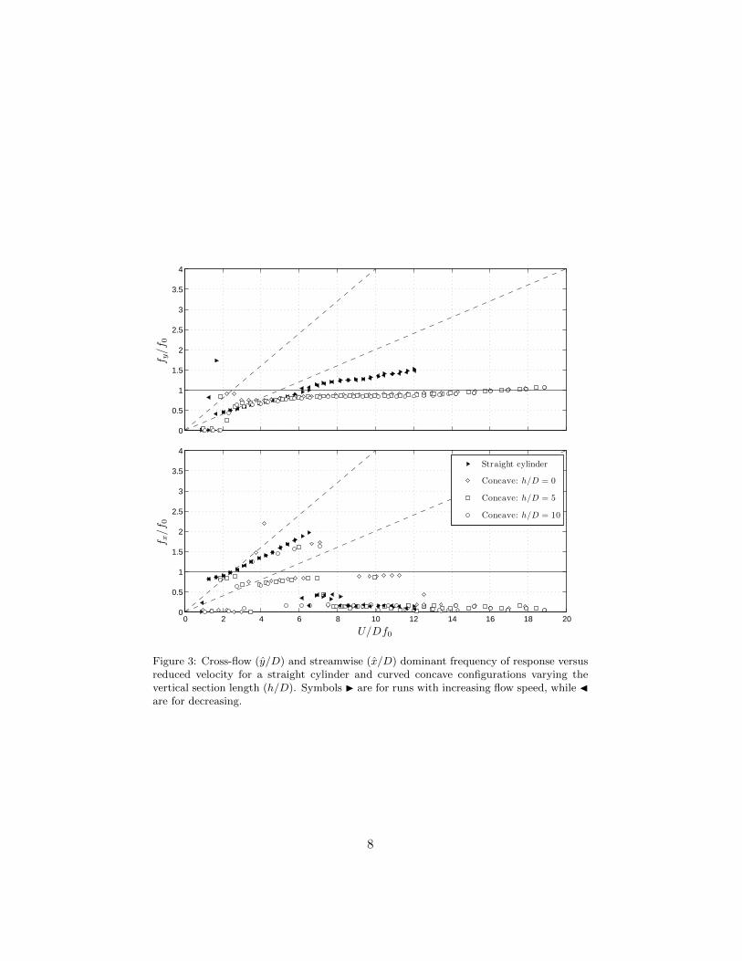
Figure 3: Cross-flow (y/D) and streamwise (x/D) dominant frequency of response versusreduced velocity for a straight cylinder and curved concave configurations varying thevertical section length (h/D). Symbols I are for runs with increasing flow speed, while Jare for decreasing.
8

0
0.2
0.4
0.6
0.8
1
1.2
1.4
1.6
1.8
y/D
0 2 4 6 8 10 12 14 16 18 200
0.1
0.2
0.3
0.4
0.5
0.6
0.7
0.8
0.9
U/Df0
x/D
Straight cylinder
Convex: h/D = 0
Convex: h/D = 5
Convex: h/D = 10
Figure 4: Cross-flow (y/D) and streamwise (x/D) amplitude of vibration versus reducedvelocity for a straight cylinder and convex configurations varying the vertical section length(h/D). Symbols I are for runs with increasing flow speed, while J are for decreasing.
9

0
0.5
1
1.5
2
2.5
3
3.5
4
f y/f 0
0 2 4 6 8 10 12 14 16 18 200
0.5
1
1.5
2
2.5
3
3.5
4
U/Df0
f x/f 0
Straight cylinder
Convex: h/D = 0
Convex: h/D = 5
Convex: h/D = 10
Figure 5: Cross-flow (y/D) and streamwise (x/D) dominant frequency of response versusreduced velocity for a straight cylinder and curved convex configurations varying thevertical section length (h/D). Symbols I are for runs with increasing flow speed, while Jare for decreasing.
10

Throughout the study, cylinder displacement amplitudes (x/D for the129
streamwise and y/D for the cross-flow directions) were found by measuring130
the root mean square value of response and multiplying by the square root131
of 2 (the so called harmonic amplitude). This is likely to give an underes-132
timation of maximum response but was judged to be perfectly acceptable133
for assessing the general behaviour of VIV, since the response is mostly134
harmonic. Results presented in the present study correspond to the dis-135
placement of the lowest point of the model, i.e., the end of the cylinder136
closer to the section floor, thus representing the maximum displacement de-137
veloped by each model. Consequently, the equivalent amplitude at the water138
surface for the cylinder with a 10D vertical section is 20% smaller than the139
amplitude indicated in the results. Applying similar corrections, amplitudes140
are 16% smaller for the cylinder with a 5D vertical section and 11% smaller141
for the cylinder with no vertical section.142
Displacements are non-dimensionalised by the cylinder diameter D. The143
dataset for the straight cylinder is repeated in Figures 2 to 5 to serve as144
reference.145
Figures 2 and 4 compare the reference cross-flow and streamwise re-146
sponses obtained from two different runs with the straight cylinder. In the147
first one, the flow speed (U) was increased in 30 steps from zero to a maxi-148
mum, while in the second it was decreased from the maximum to zero. Both149
data sets overlap rather well for all the reduced velocity range except for a150
region around U/Df0 = 6 where the well-known phenomenon of hysteresis151
in the VIV response has been observed. The streamwise VIV response also152
seems to occur in two resonance ranges (U/Df0 = 2 and 6), the so-called153
second and third instability ranges involving asymmetric vortices (Bearman,154
1984).155
Although the observed peak amplitude of y/D = 1.5 around U/Df0 = 6156
is slightly higher than other results found in the literature for similar values157
of m∗ζ (for example, Assi et al., 2009) the general behaviour of both curves158
show a typical response for 2-dof VIV. The higher amplitude found here159
could be explained by the very low mass-damping characteristics of the160
system and the geometric projection of the amplitude at the tip of the161
model and not at mid-length as usual.162
Although the cylinder was initially aligned in the vertical position, in163
flowing water the mean drag displaces the cylinder from its original location164
reaching a slightly inclined configuration from the vertical. This was judged165
not to be detrimental to the experiment; hence the inclination of the cylinder166
was not corrected between each step. The same procedure was adopted for167
the curved cylinder.168
11

Figures 3 and 5 present the dominant frequency of response versus re-169
duced velocity. Two dashed lines inclined with different slopes represent the170
region for a Strouhal number of 0.2 and 0.4, i.e., an estimation of the vortex171
shedding frequency for a straight cylinder in the cross-flow and streamwise172
direction respectively. It is clear that the straight cylinder presents a typical173
VIV response oscillating in the cross-flow direction with a frequency follow-174
ing the St = 0.2 line up to the beginning of the upper branch. Eventually,175
fy/f0 departs from St = 0.2 towards the unity value around U/Df0 = 6.176
The behaviour observed for the streamwise vibration is also typical of VIV177
with the difference that the frequency of response is twice as that for the178
cross-flow direction during much of the synchronisation range.179
4. Response of the curved cylinder180
As mentioned above, experiments with the curved cylinder were per-181
formed taking into account two distinct configurations as far as the flow182
direction is concerned. In the concave configuration the flow approaches the183
model reaching first the horizontal section. As opposed to that, in the con-184
vex configuration the horizontal section is placed downstream of the curved185
and vertical parts.186
4.1. Amplitude of vibration187
In general terms, as presented in Figures 2 and 4, the curved cylinders188
showed significantly less vibration for both concave and convex configura-189
tions when compared to the typical VIV response of the straight cylinder.190
Such a reduction is noticeable in both the cross-flow and streamwise re-191
sponses. This clearly shows that the curvature of the cylinder modifies the192
vortex shedding mechanism in a manner that the structure extracts less en-193
ergy from the flow. We shall return to this point when investigating the194
velocity flow field with PIV.195
For each concave and convex configuration, the vertical section of the196
cylinder close to the free surface was varied in three different lengths: h/D =197
0, 5 and 10. The overall response for the three values of h/D is very similar,198
showing only minor differences at the beginning of the synchronisation range199
between U/Df0 = 3.0 and 5.0. Apart from that, no distinct behaviour was200
observed as far as a variation in h/D is concerned for both concave and201
convex configurations.202
The cross-flow displacement does not reveal distinct upper and lower203
branches of vibration such as those observed for a straight cylinder, but it204
produces a smooth curve that spans the whole synchronisation region with205
12

maximum amplitude around y/D = 0.75 for the concave and 0.65 for the206
convex configurations. No hysteresis is found.207
However, the most interesting feature of such a behaviour is found when208
the convex response is compared to the concave one (Figures 2 and 4). While209
the convex curve for y/D drops immediately between U/Df0 = 8 and 10 to a210
level of y/D ≈ 0.1, the response for the concave case does not diminish, but is211
sustained for higher reduced velocities around y/D = 0.3 until the end of the212
experiment. Apparently there must be a fluid-elastic mechanism occurring213
for reduced velocities above 8.0 for the concave configuration capable of214
extracting energy from the flow to sustain vibrations around y/D = 0.3.215
We shall discuss this point later while analysing the PIV flow fields.216
In the streamwise direction the responses of the curved cylinders are dif-217
ferent from the typical VIV developed by the straight cylinder. Streamwise218
vibrations in the first and second resonance regions are totally suppressed,219
probably owing to the hydrodynamic damping effect induced by the cylin-220
der’s horizontal part. At the same time, the streamwise vibration x/D for221
the concave case also shows increasing amplitude beginning at reduced ve-222
locities higher than 10 and reaching x/D ≈ 0.35 for the highest flow speed.223
It coincides with the increased amplitude observed in the cross-flow direc-224
tion and should be related to the same excitation mechanism. Once more,225
no distinct difference in the streamwise response was observed while varying226
h/D.227
4.2. Frequency of vibration228
Figures 3 and 5 present the dominant frequency of oscillation non-dimensionalised229
by the natural frequency for both cross-flow and streamwise directions of230
motion. Results for the curved cylinder show a consistent behaviour in the231
cross-flow direction, with data points following the Strouhal line up to the232
upper branch peak but remaining closer to fy/f0 = 1.0 for the rest of the233
reduced velocity range. In the streamwise direction, we find data points fol-234
lowing both Strouhal lines and also very low frequencies indicating random235
drifts instead of periodic oscillations. Since the displacements in the stream-236
wise direction are much smaller for the curved cylinder than the straight one,237
we should expect broader frequency spectra dominating over the response.238
One might remember that the straight and curved cylinder should have239
very similar values of added mass in the cross-flow direction, but slightly240
different values in the streamwise direction due to the geometric properties241
relative to the flow. We have not taken such effect into account in this242
paper, but it might be playing an important role defining the frequencies of243
oscillation in water.244
13

0 2 4 6 8 10 12 14 16 18 20
−1
0
1
U/Df0
y/D
(a) Straight cylinder
0 2 4 6 8 10 12 14 16 18 20
−1
0
1
U/Df0
y/D
(b) Curved cylinder, concave configuraion, h/D = 10.
0 2 4 6 8 10 12 14 16 18 20
−1
0
1
U/Df0
y/D
(c) Curved cylinder, convex configuration, h/D = 10.
Figure 6: Response trajectories of motion for a (a) straight cylinder and a curved cylinderin (b) concave and (c) convex configurations. Each trajectory was taken at the reducedvelocity indicated in the horizontal axis.
4.3. Trajectories of motion245
Figure 6 qualitatively compares samples of displacement trajectories ob-246
tained for three experiments performed with the straight cylinder and the247
curved cylinders with h/D = 10. The straight cylinder presents distinct248
eight-shape figures typical of 2dof VIV owing to the 2:1 ratio on the stream-249
wise to cross-flow frequency of excitation. On the other hand, trajectories250
for both configurations of the curved cylinder reveal that the streamwise251
displacement is greatly reduced when compared to the straight cylinder.252
Both concave and convex cases show very little movement in the streamwise253
direction for the whole range of reduced velocity.254
Another interesting observation relates to the movement of both curved255
cylinders. It is clear that for reduced velocities greater than 10 the convex256
cylinder shows small displacements in both directions, while vibrations are257
sustained until the end of the experiment for the concave case as shown in258
14

Figures 2 and 4.259
5. Velocity and vorticity fields of stationary cylinders260
Two dimensional PIV (particle image velocimetry) measurements of the261
flow around the cylinder were performed, for both concave and convex con-262
figurations, on a vertical plane parallel to the plane of curvature. In addition,263
PIV measurements were also performed on three horizontal planes (marked264
H1, H2 and H3 in Figure 1 across the cylinder diameter.265
All PIV measurements were taken for Re = 1000 in the sub-critical266
Reynolds number regime found for a straight circular cylinder. According267
to Williamson (1996), the particular flow is in the shear-layer transition268
regime, characterised by an increase on the base suction, a gradual decrease269
in the Strouhal number and a decrease in the formation length of the mean270
recirculation region. These trends are caused by the developing instability271
of the separating shear layers from the sides of the body. The flow around272
a curved cylinder, which presents different elliptical cross-sections along the273
span, may behave slightly different from the above description. Further274
investigation is necessary in order to evaluate that.275
5.1. Vertical plane276
We shall start discussing the results obtained from the vertical plane, as277
presented in Figures 7 to 12. Four visualisation areas for each configuration,278
labelled A1 to A4, were conveniently distributed along the length of the279
cylinder in order to evaluate as much as possible to the flow pattern around280
the body. All four areas are in the same plane illuminated by the laser,281
which is parallel to the plane of curvature only dislocated by 1D from the282
centre of the cylinder towards the camera in order to capture the highest283
velocities induced by the vortex tubes. Figures 9 and 12 show the location284
of each area composing the flow filed along the cylinder. It is important285
to note that each velocity field was obtained from a different acquisition286
instant; hence A1, A2, A3 and A4 are not correlated in time.287
All PIV measurements were performed for a static cylinder at Re ≈ 1000.288
Of course the wake pattern for the static cylinder is expected to be different289
from the wake of an oscillating cylinder, but even an analysis of a fixed290
body can contribute to the understanding of the complex vortex-structure291
interaction occurring during the response. A similar approach was employed292
by Miliou et al. (2007) who performed numerical simulations for a static,293
curved cylinder between Re = 100 and 500. The same colour scales have294
15

been employed from Figures 7 to 12 to allow for direct comparison of velocity295
magnitude and vorticity contours.296
With that in mind, let us analyse first the flow pattern around the con-297
cave configuration in Figures 7 to 9. The overall flow around the body can298
be divided in two parts:299
(I) Areas A1 and A2 show the region where the flow is mostly parallel to300
the axis of the cylinder. Therefore, no clear vortex tubes are observed with301
concentrated axial vorticity. Instead, the flow along the horizontal length is302
disturbed by the separation occurring at the tip of the cylinder. Area A1303
shows the flow approaching the disk facing upstream and separating into a304
recirculation bubble. The periodicity of the shedding associated with this305
region is also related to the flow speed and the diameter D, but no coherent306
vortices parallel to the cylinder are able to form. As a consequence, a cascade307
of small vortices is convected downstream along the horizontal length (see308
area A2) reaching the beginning of the curved section.309
(II) Areas A3 and A4 show the region where the flow is mainly perpen-310
dicular to the axis of the cylinder. Coherent vortex tubes tend to form fol-311
lowing the curvature of the body, but further downstream they are stretched312
and rapidly breakdown into smaller vortices that are convected by the flow.313
Area A3 shows the instant when a vortex tube is shed almost tangent to314
the curvature, while area A4, around the vertical section, reveal a formation315
region more or less aligned with the axis of the cylinder. Streamlines drawn316
in areas A3 and A4 reveal a non-negligible velocity component deflecting317
the flow downwards immediately after the vortex formation region. As we318
move along the cylinder towards the water line from A3 to A4 the down-319
ward component is gradually reduced until it eventually disappears towards320
the upper half of A4. This region marks the competition between two wake321
modes existent along the transition from curved to straight cylinder. This322
looks similar to Figure 15 in Miliou et al. (2007), with Re = 100, although323
without the cylinder horizontal section therein.324
Analysing the flow pattern for the convex configuration in Figures 10 to325
12 we notice two striking differences:326
Firstly, because the flow approaching the convex body does not encounter327
a blunt disk facing upstream, no strong separation or recirculation bubble328
is formed. As a consequence, the horizontal section seen in areas A1 and329
A2 is not exposed to a disturbed, unsteady flow parallel to the axis of the330
cylinder. In fact, A1 and A2 reveal that the upper half of the horizontal331
length is exposed to a periodic flow formed by a regular wake, while the332
bottom half experiences almost no perturbation, with streamlines showing333
a well behaved flow field parallel to the axis.334
16

Figure 7: Composition of instantaneous PIV velocity fields for concave configuration withh/D = 5.
Figure 8: Composition of instantaneous PIV vorticity fields for concave configuration withh/D = 5.
17

CONCAVE: A1
(a) Velocity magnitude, A1 (b) Vorticity contours, A1
CONCAVE: A2
(c) Velocity magnitude, A2 (d) Vorticity contours, A2
CONCAVE: A3
(e) Velocity magnitude, A3 (f) Vorticity contours, A3
CONCAVE: A4
(g) Velocity magnitude, A4 (h) Vorticity contours, A4
Figure 9: Detailed velocity and vorticity fields from Figures 7 and 8. Flow direction isfrom right to left. Re = 1000. Colour scale for velocity magnitude is from 0.004m/s (blue)to 0.05m/s (red). Colour scale for vorticity contours in in the range ±0, 004s−1. (Velocityfields do not correspond to the vorticity fields in time.)
18

Figure 10: Composition of instantaneous PIV velocity fields for convex configuration withh/D = 5.
Figure 11: Composition of instantaneous PIV vorticity fields for convex configuration withh/D = 5.
19
CONVEX: A1
(a) Velocity magnitude, A1 (b) Vorticity contours, A1
CONVEX: A2
(c) Velocity magnitude, A2 (d) Vorticity contours, A2
CONVEX: A3
(e) Velocity magnitude, A3 (f) Vorticity contours, A3
CONVEX: A4
(g) Velocity magnitude, A4 (h) Vorticity contours, A4
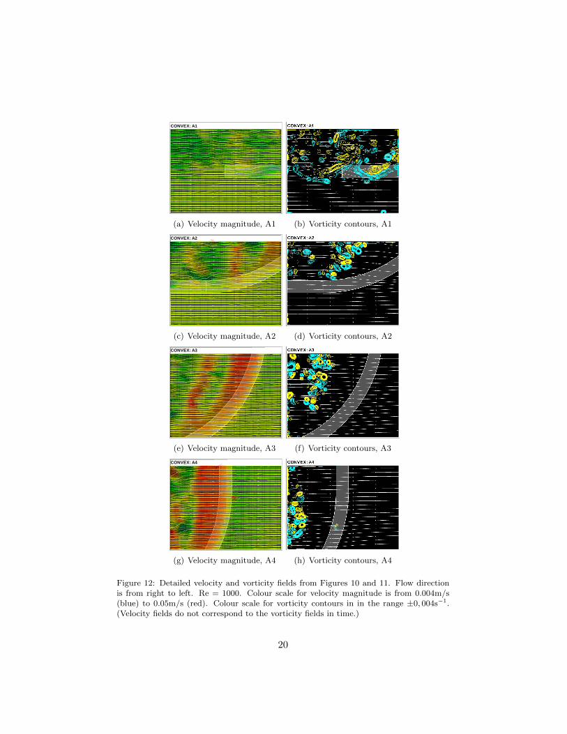
Figure 12: Detailed velocity and vorticity fields from Figures 10 and 11. Flow directionis from right to left. Re = 1000. Colour scale for velocity magnitude is from 0.004m/s(blue) to 0.05m/s (red). Colour scale for vorticity contours in in the range ±0, 004s−1.(Velocity fields do not correspond to the vorticity fields in time.)
20

Secondly, looking at the upper half of the body (A3 and A4) we notice335
much stronger and coherent vortex tubes when compared to the flow around336
the concave configuration. Area A3 reveals some kind of vortex dislocation337
after a formation region that increases in length as we move upwards. Be-338
cause the convex geometry does not encourage the vortex tubes to stretch339
and break, a periodic wake seems to be sustained farther downstream. In340
contrast with the flow around the concave configuration, the velocity field341
around the curved section has a non-negligible vertical component upwards.342
It is stronger in A2 and is gradually reduced as we move upwards along the343
curvature in A3. This looks similar to Figure 3 in Miliou et al. (2007) for344
Re = 100.345
Gallardo et al. (2011) stated that there is a certain degree of alignment346
of the flow structures with the axial curvature of the cylinder, which tilts347
the flow structures with respect to the vertical direction. Figures 12(e) and348
12(f) capture this behaviour, also recognised in Figure 2 of Gallardo et al.349
(2011) and Figure 8 of Miliou et al. (2007).350
5.2. Horizontal planes351
Figures 13 and 14 present PIV velocity fields for the three horizontal352
planes indicated by H1, H2 and H3 in Figure 1. All measurements were353
performed with h/D = 5. Plane H1 was positioned at the transition from354
the straight to the curved section of the model, i.e., 5D below the water355
line. Plane H2 was located 5D below that position and plane H3 another356
5D down towards the floor.357
Figure 13 presents results for the concave configuration. The two cam-358
eras were positioned underneath the model as viewing from the bottom359
through the glass floor. A light grey circle or ellipse marks the cross section360
of the cylinder at the illuminated plane. A dark grey rectangle represents361
the part of the curved model in front of the laser plane, while a dashed line362
illustrates the projection of the model behind the plane. Each image is com-363
posed of two PIV areas taken simultaneously; for some cases they overlap,364
for others they are apart.365
In Figure 13(a), for the horizontal plane at the transition from the366
straight to the curved section, we notice a wider wake with a longer for-367
mation region that generates stronger vortices. This formation is related368
to the strong vortex tubes parallel to the straight section presented in Fig-369
ure 9(g). Moving down to plane H2, the cross section of the cylinder turns370
into an ellipse. The wake becomes much narrower with a short formation371
length and no strong vortices are distinguishable in the downstream flow.372
Figure 9(e) also showed that an oblique vortex tube would form closer to373
21

(a) Plane H1
(b) Plane H2
(c) Plane H3
Figure 13: Velocity fields for horizontal planes across the concave configuration. Pleaserefer to Figure 1 for positions. Flow direction is from right to left. Re = 1000. Colourscale for velocity magnitude is from 0.004m/s (blue) to 0.05m/s (red).
22
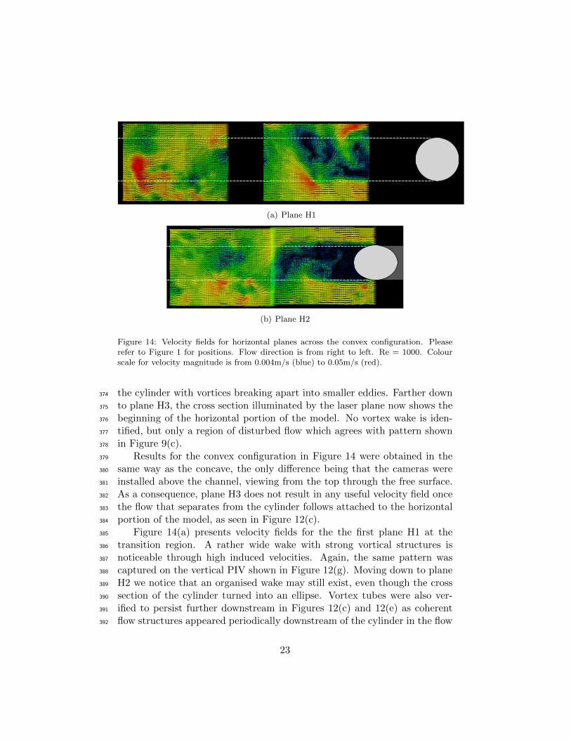
(a) Plane H1
(b) Plane H2
Figure 14: Velocity fields for horizontal planes across the convex configuration. Pleaserefer to Figure 1 for positions. Flow direction is from right to left. Re = 1000. Colourscale for velocity magnitude is from 0.004m/s (blue) to 0.05m/s (red).
the cylinder with vortices breaking apart into smaller eddies. Farther down374
to plane H3, the cross section illuminated by the laser plane now shows the375
beginning of the horizontal portion of the model. No vortex wake is iden-376
tified, but only a region of disturbed flow which agrees with pattern shown377
in Figure 9(c).378
Results for the convex configuration in Figure 14 were obtained in the379
same way as the concave, the only difference being that the cameras were380
installed above the channel, viewing from the top through the free surface.381
As a consequence, plane H3 does not result in any useful velocity field once382
the flow that separates from the cylinder follows attached to the horizontal383
portion of the model, as seen in Figure 12(c).384
Figure 14(a) presents velocity fields for the the first plane H1 at the385
transition region. A rather wide wake with strong vortical structures is386
noticeable through high induced velocities. Again, the same pattern was387
captured on the vertical PIV shown in Figure 12(g). Moving down to plane388
H2 we notice that an organised wake may still exist, even though the cross389
section of the cylinder turned into an ellipse. Vortex tubes were also ver-390
ified to persist further downstream in Figures 12(c) and 12(e) as coherent391
flow structures appeared periodically downstream of the cylinder in the flow392
23

fields. Similar vortex structures were verified by Miliou et al. (2007) and393
Gallardo et al. (2011). This proves that the convex configuration is more394
prone to produce correlated vortex tubes along the curved length of the395
cylinder, while in the concave configuration vortices soon break apart as396
they are convected downstream.397
Based on the results of Gallardo et al. (2011) for the convex configu-398
ration, one can observe that the interaction of the shear layers and thus399
the vortex formation length is a function of the cross-sectional shape being400
circular or elliptical, here represented by different planes along the cylinder401
span as can be seen in Figure 14 and also in Figure 3 of Gallardo et al.402
(2011).403
Plane H1 in Figure 14(a), which corresponds to plane z/D = 16 in404
Gallardo et al. (2011), shows that the shear layers interact in a farther405
downstream position from the body and the wake is wider compared to a406
horizontal position of the H2 plane in Figure 14(b) where the cross-section of407
the cylinder is elliptical. In the latter case, seen also at the z/D = 8 plane in408
Gallardo et al. (2011), there are vortices produced within the recirculation409
region exhibiting the wavier shear layers.410
6. The excitation mechanism411
The main question to be answered by the present study is concerned412
with the fact that the amplitude in the cross-flow direction for the convex413
configuration is able to drop down to 0.1 for high reduced velocities while414
the concave configuration sustains vibration around 0.35. We believe this415
distinct behaviour between the convex and the concave configurations is416
related to the wake interference happening in the lower half of the cylinder417
due to perturbations generated in the horizontal section when it is positioned418
upstream.419
In the concave configuration the horizontal part of the cylinder is located420
upstream of the curved and vertical parts. The approaching flow encoun-421
ters a circular blunt leading edge with a clear separation region around the422
circumference (Figure 9(a)). The flow that separates at the leading edge423
tends to create a separation bubble and latter reattaches along the horizon-424
tal section of the cylinder. Because the cylinder already presents cross-flow425
and streamwise vibrations, the three-dimensional separation bubble will not426
find a stable configuration nor a definite reattachment region, instead it will427
develop a periodic behaviour that may result in three-dimensional vortices428
being shed downstream, reaching the other parts of the cylinder. This is429
very clear in areas A1 and A2 of Figures 7 and 9 for the static cylinder.430
24

The fluid-elastic mechanism behind the response may be a composition431
of different phenomena acting at the same time. We believe this interac-432
tion between the disturbed flow from the upstream horizontal part with the433
curved and vertical parts is responsible for sustaining the level of vibration434
around y/D = 0.35 and x/D = 0.35. We suggest such an interaction may435
be occurring in the following forms:436
(i) Vortices generated along the horizontal section may impinge on the437
curved part generating impulses in the same manner that large eddies of438
turbulence induce buffeting on elastic structures. Because the concave con-439
figuration has a longer section immersed in such a disturbed wake it is more440
susceptible to buffet. Evidence that a buffeting-like phenomenon might be441
occurring is that the streamwise vibration shows a considerable increase442
in amplitude with increasing flow speed further out of the synchronisation443
range. Figure 6(b) also reveals that these vibrations are not harmonic and444
may even be chaotic, another evidence supporting the buffeting-excitation445
hypothesis.446
(ii) The disturbed flow from the horizontal part may be disturbing and447
disrupting the vortex shedding mechanism from the curved and vertical sec-448
tions, for example uncorrelating the vortex shedding mechanism in a curved449
region of the cylinder near the horizontal part. Also, the vortex wake along450
the curved-vertical half of the concave cylinder showed less correlation along451
the span, resulting in a lower peak of vibration during the synchronisation452
range.453
(iii) Because the concave configuration has a fixed separation ring at the454
circle facing upstream, there might be some galloping-like instability related455
to the separation and reattachment of the three-dimensional bubble. This456
could generate non-resonant forces that could sustain some level of vibration457
for reduced velocities above the synchronisation range.458
(iv) Finally, the concave configuration might experience some kind of459
instability related to the geometric arrangement of the experiment. Because460
the centre of pressure is located upstream of the vertical axis of the pendulum461
a minute deflection of the cylinder may result in a resolved force that will462
increase displacement. The opposite is true for the convex configuration in463
which the centre of pressure downstream of the vertical axis of the pendulum464
can only generate stabilising forces.465
Of course all four mechanisms suggested above may also be occurring466
simultaneously or it may not even be possible to explain them separately.467
In addition, they might as well be very dependent on Reynolds number and468
amplitude of vibration.469
25

7. Conclusions470
We have experimentally investigated the two-degree-of-freedom VIV re-471
sponse of a rigid, curved circular cylinder with a low mass-damping ratio.472
With regard to the approaching flow (Reynolds number is in the range of473
750-15,000) both concave and convex configurations were considered and the474
measured responses were compared with those of a typical straight cylinder.475
In summary, we conclude that:476
(i) In general terms, a curved cylinder presents a lower peak of amplitude477
of vibration in both the cross-flow and streamwise direction when compared478
to a straight cylinder. Nevertheless, a considerable level of streamwise vi-479
bration, not attributed to VIV, was observed for reduced velocity as high as480
18.481
(ii) Although the peak amplitude is reduced, a curved cylinder may482
present a significant level of vibration that is sustained for higher values of483
reduced velocity beyond the end of the typical synchronisation range.484
(iii) The concave configuration shows a considerable level of cross-flow485
vibration around y/d = 0.35 up to the highest reduced velocity performed486
in this experiment.487
(iv) The overall response showed little dependency on the vertical length488
immediately below the water line, at least for a section varying between489
h/D = 0 and 10.490
(v) From the PIV study on a stationary curved cylinder, we suggest491
that the flow-structure interaction mechanism that differentiates the concave492
from the convex cylinder response may have its origin in the disturbed flow493
that separates from the horizontal part located upstream. This could be494
related to buffeting, galloping, disturbed VIV or geometric instabilities.495
Future work should concentrate on correlated PIV analyses of the vor-496
tex formation along the curvature as well as on measurements of the flow497
field on planes perpendicular to the plane of curvature. An investigation of498
the interference effect generated by the separation at the tip of the horizon-499
tal section could also help towards understanding the response. PIV and500
instantaneous force measurements for an oscillating cylinder, especially at501
high reduced velocities, could throw some light into the actual mechanism502
of excitation.503
Acknowledgements504
G.R.S. Assi wishes to acknowledge the support of CNPq (308916/2012-505
3) and FAPESP (11/00205-6). C.M. Freire acknowledges support from506
26

FAPESP (10/00053-9). N. Srinil is grateful to the “Sir David Anderson507
Award” from the University of Strathclyde and the “Early Career Researcher508
International Exchange Award” supported by The Scottish Funding Coun-509
cil.510
References511
Assi, G.R.S., Meneghini, J.R., Aranha, J.A.P., Bearman, P.W., Casaprima,512
E. 2006 Experimental investigation of flow-induced vibration interference513
between two circular cylinders. J. Fluids and Structures, 22, 819-827.514
Assi, G.R.S., Bearman, P.W and Kitney, N 2009 Low Drag Solutions for515
Suppressing Vortex-Induced Vibration of Circular Cylinders. J. Fluids and516
Structures 25, 1-10.517
Assi, G.R.S., Bearman, P.W., Meneghini, J.R. 2010 On the wake-induced518
vibration of tandem circular cylinders: the vortex interaction excitation519
mechanism J. Fluid Mech., 661, 365-401.520
Assi, G.R.S., Bearman, P.W., Kitney, N., Tognarelli, M.A. 2010b Suppres-521
sion of Wake-Induced Vibration of Tandem Cylinders with Free-to-Rotate522
Control Plates. J. Fluids and Structures, 26, 1045-1057.523
Bearman, P.W. 1984 Vortex shedding from oscillating bluff bodies. Annu.524
Rev. Fluid Mech., 16, 195-222.525
Freire, C.M., Korkischko, I., Meneghini, J.R. 2009 Development of an elastic526
base with tow degrees of freedom for VIV studies. In the proceedings of527
COBEM 2009 – 20th International Congress of Mechanical Engineering,528
2009, Gramado, Brazil.529
Freire, C.M., Meneghini, J.R. 2010. Experimental investigation of VIV on a530
circular cylinder mounted on an articulated elastic base with two degrees-531
of-freedom. In the proceedings of BBVIV6 – IUTAM Symposium on Bluff532
Body Wakes and Vortex-Induced Vibrations, 2010, Capri, Italy.533
Freire, C.M., Korkischko, I., Meneghini, J.R. 2011 Definning a parame-534
ter of effectiveness for the suppression of vortex-induced vibration. In535
the proceedings of OMAE2011 – 30th International Conference on Ocean,536
Offshore and Arctic Engineering, 2011, Rotterdam, The Netherlands.537
Gallardo, J. P., Pettersen, B., Andersson, H. I. 2011 Dynamics in the tur-538
bulent wake of a curved circular cylinder. J. Phys. Conf. Ser. 318, 062008.539
27

Miliou, A., De Vecchi, A., Sherwin, S.J., Graham, M.R. 2007 Wake dynam-540
ics of external flow past a curved circular cylinder with the free stream541
aligned with the plane of curvature J. Fluid Mech., 592, 89-115.542
Srinil, N. 2010 Multi-mode interactions in vortex-induced vibrations of flex-543
ible curved/straight structures with geometric nonlinearities J. Fluids and544
Structures, 26, 1098-1122.545
Williamson, C. H. K. 1996 Vortex dynamics in the cylinder wake Annu.546
Rev. Fluid Mech., 28, 477-539.547
28