Embed Size (px)
Citation preview

ATM System
Computer Science and Engineering OOSD Lab
Experiment No: 2
A STUDY EXPERIMENT ON RATIONAL ROSE
Experiment Date:
ATM System
Computer Science and Engineering OOSD Lab
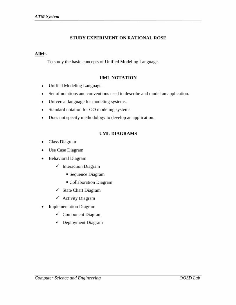
STUDY EXPERIMENT ON RATIONAL ROSE
AIM:-
To study the basic concepts of Unified Modeling Language.
UML NOTATION
Unified Modeling Language.
Set of notations and conventions used to describe and model an application.
Universal language for modeling systems.
Standard notation for OO modeling systems.
Does not specify methodology to develop an application.
UML DIAGRAMS
Class Diagram
Use Case Diagram
Behavioral Diagram
Interaction Diagram
Sequence Diagram
Collaboration Diagram
State Chart Diagram
Activity Diagram
Implementation Diagram
Component Diagram
Deployment Diagram

ATM System
Computer Science and Engineering OOSD Lab
CLASS DIAGRAM
Shows the static structure of the model.
Collection of static modeling elements such as classes and their relationships
connected as a graph.
Provides visual representation of objects, relationships and their structures.
Class:-
A class is a set of objects that share a common structure and common behavior.
It is represented as:
Interface:-
Specifies the externally-visible operations of a class and/or component.
Association:-
Model properties of associations.
The properties are stored in a class and linked to the association relationship.
Example,
Generalization:-
A generalize relationship is a relationship between a more general class or use
case and a more specific class or use case.
Example,
<Class Name>
<Attributes>
<Operations>
Bank Account Person

ATM System
Computer Science and Engineering OOSD Lab
USE CASE DIAGRAM
Set of use cases enclosed by system boundary, communication association
between actors and use cases, and generalization among use cases.
Actors:-
External factors that interacts with the system from the user's perspective.
Use Cases:-
Set of scenarios that describe how actor uses the system.
Represented as,
Relationship:-
Communication – communications with the use case normally.
Uses – Shown by generalization arrow from the use cases.
Extends – Used when one case does more than another that is similar to it.
Vehicle
TruckBus Car
ATM System
Computer Science and Engineering OOSD Lab
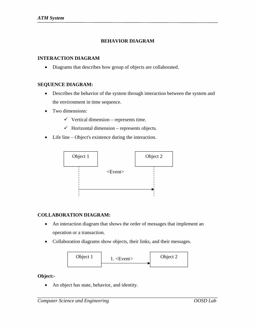
BEHAVIOR DIAGRAM
INTERACTION DIAGRAM
Diagrams that describes how group of objects are collaborated.
SEQUENCE DIAGRAM:
Describes the behavior of the system through interaction between the system and
the environment in time sequence.
Two dimensions:
Vertical dimension – represents time.
Horizontal dimension – represents objects.
Life line – Object's existence during the interaction.
<Event>
COLLABORATION DIAGRAM:
An interaction diagram that shows the order of messages that implement an
operation or a transaction.
Collaboration diagrams show objects, their links, and their messages.
1. <Event>
Object:-
An object has state, behavior, and identity.
Object 1 Object 2
Object 1 Object 2
ATM System
Computer Science and Engineering OOSD Lab
Objects interact through their links to other objects.
Link:-
A link is an instance of an association, analogous to an object.
Message:-
A message is the communication carried between two objects that trigger an
event.
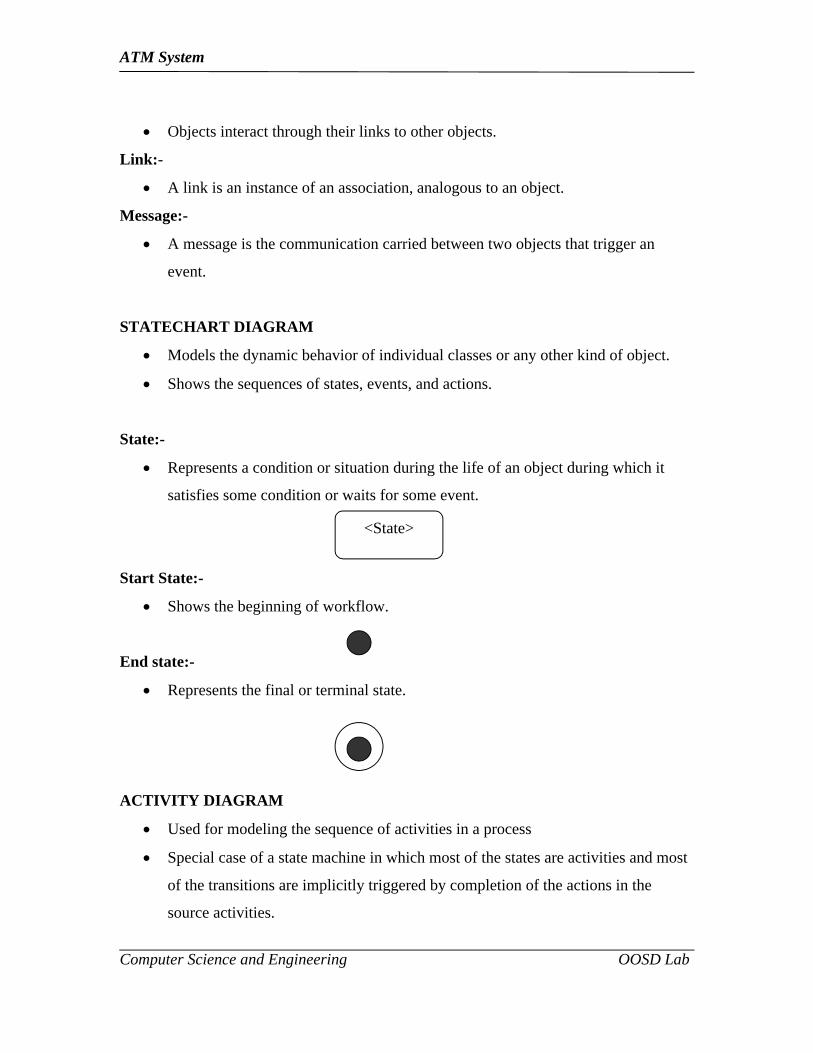
STATECHART DIAGRAM
Models the dynamic behavior of individual classes or any other kind of object.
Shows the sequences of states, events, and actions.
State:-
Represents a condition or situation during the life of an object during which it
satisfies some condition or waits for some event.
Start State:-
Shows the beginning of workflow.
End state:-
Represents the final or terminal state.
ACTIVITY DIAGRAM
Used for modeling the sequence of activities in a process
Special case of a state machine in which most of the states are activities and most
of the transitions are implicitly triggered by completion of the actions in the
source activities.
<State>
ATM System
Computer Science and Engineering OOSD Lab
Activity:-
Represents the performance of task or duty in a workflow.
Swim lanes:-
Represents organizational units or roles within a business model.
IMPLEMENTATION DIAGRAM
Shows the implementation phase of system development.
Two types of implementation diagrams:
Component diagram
Deployment diagram
COMPONENT DIAGRAM
Models the physical components in the design.
A graph of the design’s components connected by dependency relationships.
Includes concept of packages.
Package is used to show how classes are grouped together.
DEPLOYMENT DIAGRAM
Shows the configuration of runtime processing elements and software
components.
It is a graph of nodes connected by communication association.
Nodes are the components that are connected to other components through
dependencies.
Used in conjunction with component diagrams to show the distribution of
physical modules.
<Activity>

ATM System
Computer Science and Engineering OOSD Lab
RESULT:-
Thus the different conceptual models under UML have been studied.
ATM System
Computer Science and Engineering OOSD Lab
Experiment No: 3
SOFTWARE REQUIREMENTS SPECIFICATION FOR ATM SYSTEM
Experiment Date:

ATM System
Computer Science and Engineering OOSD Lab
SOFTWARE REQUIREMENT SPECIFICATION
Aim:
The aim of the experiment is to prepare and Document the Software Requirements
Specification for the project “ATM System”
1. Introduction
1.1 Purpose
1.2 Scope
1.3 Definition, Acronyms, and Abbreviations
1.4 Reference
1.5 Overview
2. Overall Description
2.1 Product Perspective
2.1.1 System Interfaces
2.1.2 User Interfaces
2.1.3 Hardware Interfaces
2.1.4 Software Interfaces
2.1.5 Communication Interfaces
2.1.6 Memory Interfaces
2.1.7 Operations
2.1.8 Site Adaptation Requirements
2.2 Product Functions
2.3 User Characteristics
2.4 Constraints
2.5 Assumptions and Dependencies

ATM System
Computer Science and Engineering OOSD Lab
3. Specific Requirements
3.1 External Interfaces Requirements
3.1.1 User Interfaces
Login Screen
User details
Account details
Administrator
3.1.2 Hardware Interfaces
3.1.2 Software Interfaces
3.1.3 Communication Interfaces
3.2 Software Product Features
3.2.1 Question Details Maintenance
3.2.2 Administrator Details Maintenance
3.2.3 Report Generation
3.3 Performance Requirements
3.4 Design Constraints
3.5 Software System Attributes
3.6 Logical Database Requirements
3.7 Other Requirements
1. Introduction
This document aim to defining the overall software requirements for “ATM system”.
The final product will entirely depend on this documentation.
1.1 Purpose
This specific documentation describes the capabilities that will be provided by the
software application “ATM System”. It also defines the required constraints of the
system and it is useful for development team, testing and end users of the product.

ATM System
Computer Science and Engineering OOSD Lab
1.2 Scope
The main of this project is to implement online Atm system. Here this will provide a time
safety for the user to make transactions.
This project has the following features:
Registration process.
Account process.
Amount withdraw process.
1.3 Definitions Acronyms and Abbreviation
ATM – Automatic Teller Machine.
ACC NO- .Account Number
1.4 Reference
(i) IEEE Recommended practice for SRS IEEE Standard 830-1993
(ii) “Object Oriented Analysis and design” Ali Bahrami, Object Oriented System
Development, using UML, McGraw –Hill international Edition, 1999
1.5 Overview
The SRS document gives an idea about the requirements and features of the system.
2 Overall Descriptions
The system Atm is developed to automate the Atm system in Work places.
2.1 Product Perspective
The application will be a window-based, independent software product.
2.1.1 System Interfaces
None

ATM System
Computer Science and Engineering OOSD Lab
2.1.2 User Interfaces
The following are the screen provided in the application.
Login Screen.
User name and password.
User registration.
Question and answer.
2.1.3 Hardware Interface
Minimum Requirements of the system.
Processor-486D/66Mhzor higher processor (Pentium)
Memory- 16MB of RAM
Monitor- 17Inch monitor
CD RW Drive-52X
USB Port
Printer
2.1.4 Software Interfaces
Operating system-Windows XP
Front End Tool –Visual Basic 6.0
Back End Tool-Oracle
UML Software- Star UML5.0
2.1.5 Communication Interfaces
Not required
2.1.5 Memory Constraints
Hard Disk-5GB
RAM – 128MB
ATM System
Computer Science and Engineering OOSD Lab
2.1.6 Operations
Insert- insert the questions in the database
Delete- delete the questions from the database
Update- update the questions and answers in the database
View - view the result from the database
2.1.7 Site Adaptation Requirements
The stand alone system must able to support the hardware and software interfaces.
2.2 Product Functions
A summary of major functions that the software will perform.
2.3 User Characteristics
Administrator - he must know how to operate the software. He must have a
technical knowledge to handle the system. He must be able to upload the question
User - he must how to operate the software and with draw the Amount.
2.4 Constraints
The developed system is meant for standalone system only. So it cannot be used for on
line management.
2.5 Assumptions and Dependencies
The user details in the database entirely depend upon the information provided in login
that are provided by the administrator.
Atm system works on the assumption that the user attends the test.
3 Specific Requirements
This section contains the software requirements to a level of detail sufficient to enable
designers to design the system and tester to test the system.

ATM System
Computer Science and Engineering OOSD Lab
3.1 External Interface Requirements
• User Interface
• Amount withdrawal:
• Pin No:
• Account Details:
• Balance Enquiry:
3.2 Login screen
Username: String of the alphabets of length up to 8
Password: String of Alphabets of Length up to 6
Role: Two types of role will be there Administrator, user and coordinator.
3.1.1 Main Menu Screen
User details
Account details
Balance details.
Amount Withdrawal.
3.1.2 Hardware Interface
Minimum Requirements of the system.
Processor-486D/66MHzor higher processor (Pentium)
Memory- 16MB of RAM
Monitor- 17Inch monitor
CD RW Drive-52X
USB Port
Printer

ATM System
Computer Science and Engineering OOSD Lab
3.1.3 Software Interfaces
Operating system-Windows XP
Front End Tool –PHP
Back End Tool-MYSQL
UML Software- Star UML5.0
3.1.4 Communication Interfaces
• Not Required
3.2 Software Product features
Account detail maintenance
User detail maintenance
3.2.1 Account Details maintenance
Description:
It contains the details of the Account holders and their respective Bank account
Details. Sequencing information
Error Handling/Response to abnormal
3.2.2 User Detail Maintenance
Description:
It contains the details of the user such as user name, Acc no, Amount details, address,
age, branch, job etc.
Sequencing information
Error Handling/Response to abnormal
3.2.3 User details Report
Name user_id Password address age
ATM System
Computer Science and Engineering OOSD Lab
3.3 Performance requirements
None
3.4 Design Constraints
None
3.5 Software System Attributes
Usability: It is used to write the test through online and reduce manpower. it is
computerized.
3.6 Logical Database Requirements
The following information will be placed in the database
User Details: User details includes user name, type of account, address, age etc.
ACcount Details: Account details include the balance details,account duration etc.
3.7 Other Requirements
None

ATM System
Computer Science and Engineering OOSD Lab
Result:
The Software Requirements Specification for the project “ATM SYSTEM” has
been analyzed and documented successfully.
ATM System
Computer Science and Engineering OOSD Lab
Experiment No: 4
OBJECT ORIENTED DESIGN FOR ATM SYSTEM
Experiment Date:
ATM System
Computer Science and Engineering OOSD Lab
OBJECT ORIENTED DESIGN FOR ATM SYSTEM
AIM:
The aim of the experiment is to prepare document and the object oriented diagram for the
project ATM System.
USE CASE DIAGRAM:
Set of use cases enclosed by system boundary, communication association
between actors and use cases, and generalization among use cases.
ACTORS:
User
Machine
SENARIOS
Enter pin number
Pin code.
Pin Accept.
Balance.
Amount With draw.
Fee pay.
Collect Cash.
Exit.

ATM System
Computer Science and Engineering OOSD Lab
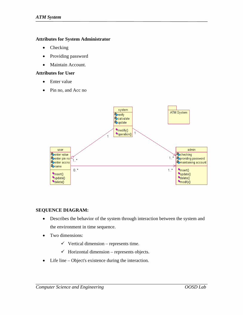
CLASS DIAGRAM:
Shows the static structure of the model.
Collection of static modeling elements such as classes and their relationships
connected as a graph.
Provides visual representation of objects, relationships and their structures.
Classes used:
System.
Administrator
User.
Attributes for System
Verify.
Calculate.
Update.
ATM System
Computer Science and Engineering OOSD Lab
Attributes for System Administrator
Checking
Providing password
Maintain Account.
Attributes for User
Enter value
Pin no, and Acc no
SEQUENCE DIAGRAM:
Describes the behavior of the system through interaction between the system and
the environment in time sequence.
Two dimensions:
Vertical dimension – represents time.
Horizontal dimension – represents objects.
Life line – Object's existence during the interaction.

ATM System
Computer Science and Engineering OOSD Lab
: UserCardReader Screen Customer
AccountCash
dispatches
insert the card
Read Card No
Invalid Card(OP)
Initialize Screen
Activate Account
Prompt for pin
Enter the pin no
Prompt for transaction
Invalid pin no(OP)
Cash withdraw
Prompt for amount
Enter the amount
Check balance
Verify funds
Detect funds
Invalid query
Provide cash
Provide reciept
Collect cash and reciept
Eject card
OBJECTS FOR User:

ATM System
Computer Science and Engineering OOSD Lab
Card Reader
Screen
Customer Account
Cash Dispatch.
SEQUENCES FOR User Module:
Insert the card
Read Card No
Invalid Card Operation
Initialize screen
Active Account.
Prompt for Account.
Enter the pin number
Invalid pin no
Cash withdraw
Invalid query
Check balance
Verify Funds
Detect Funds
Provide Cash
Provide Receipt
Eject Card

ATM System
Computer Science and Engineering OOSD Lab
Screen : Machine
Card reader Customer Account
Cash dispatches
Prompt for amount
Provide cash and receipt
accept card
Accept pin no
Account verified
Transaction details
SEQUENCES FOR MACHINE:
Accept card
Accept Pin no
Account Verified
Transaction Details
Prompt for Amount.
ATM System
Computer Science and Engineering OOSD Lab
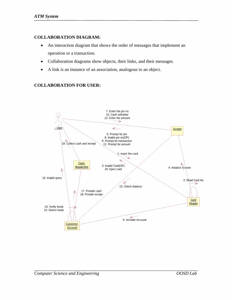
COLLABORATION DIAGRAM:
An interaction diagram that shows the order of messages that implement an
operation or a transaction.
Collaboration diagrams show objects, their links, and their messages.
A link is an instance of an association, analogous to an object.
COLLABORATION FOR USER:
: User
CardReader
Screen
Customer Account
Cash dispatches
2: Read Card No
14: Verify funds15: Detect funds
1: insert the card
3: Invalid Card(OP)20: Eject card 4: Initialize Screen
5: Activate Account
6: Prompt for pin8: Invalid pin no(OP)
9: Prompt for transaction11: Prompt for amount
7: Enter the pin no10: Cash withdraw
12: Enter the amount
13: Check balance
16: Invalid query
17: Provide cash18: Provide reciept
19: Collect cash and reciept
ATM System
Computer Science and Engineering OOSD Lab
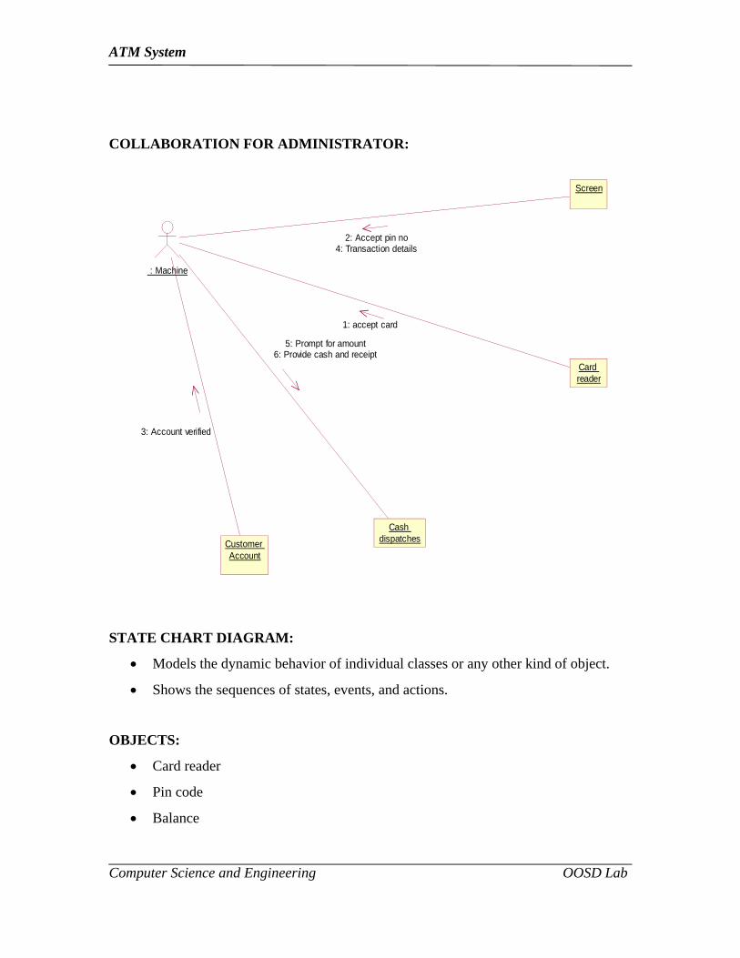
COLLABORATION FOR ADMINISTRATOR:
: Machine
Card reader
Screen
Customer Account
Cash dispatches
5: Prompt for amount6: Provide cash and receipt
1: accept card
2: Accept pin no4: Transaction details
3: Account verified
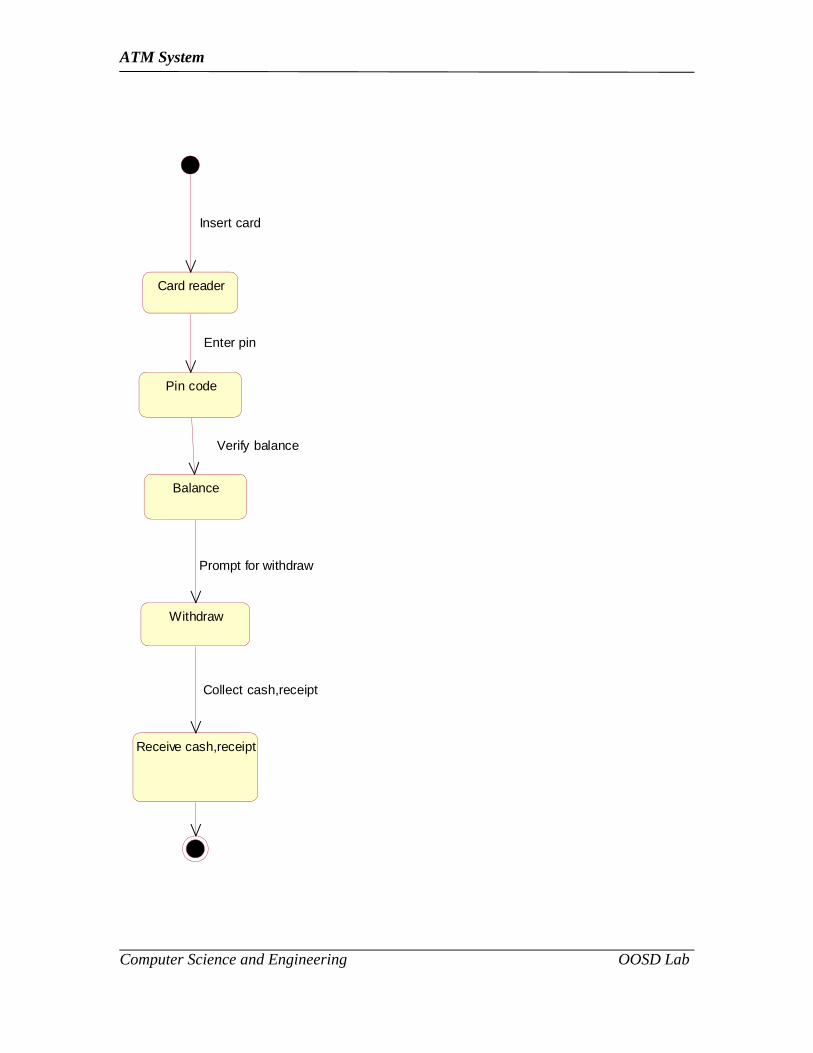
STATE CHART DIAGRAM:
Models the dynamic behavior of individual classes or any other kind of object.
Shows the sequences of states, events, and actions.
OBJECTS:
Card reader
Pin code
Balance

ATM System
Computer Science and Engineering OOSD Lab
Withdraw
Receive Cash
OPERATIONS:
Insert Card
Enter Pin no
Verify Balance
Prompt for Withdraw
Collect Cash
Receipt
ATM System
Computer Science and Engineering OOSD Lab
Pin code
Card reader
Balance
Receive cash,receipt
Insert card
Withdraw
Enter pin
Verify balance
Prompt for withdraw
Collect cash,receipt

ATM System
Computer Science and Engineering OOSD Lab
COMPONENT DIAGRAM:
Models the physical components in the design.
A graph of the design’s components connected by dependency relationships.
Includes concept of packages.
Package is used to show how classes are grouped together.
COMPONENTS USED:
ATM.Exe
Transaction
Verification
ATM.Exe
Transaction verification
Transaction.cpp verification.cpp
ATM System
Computer Science and Engineering OOSD Lab
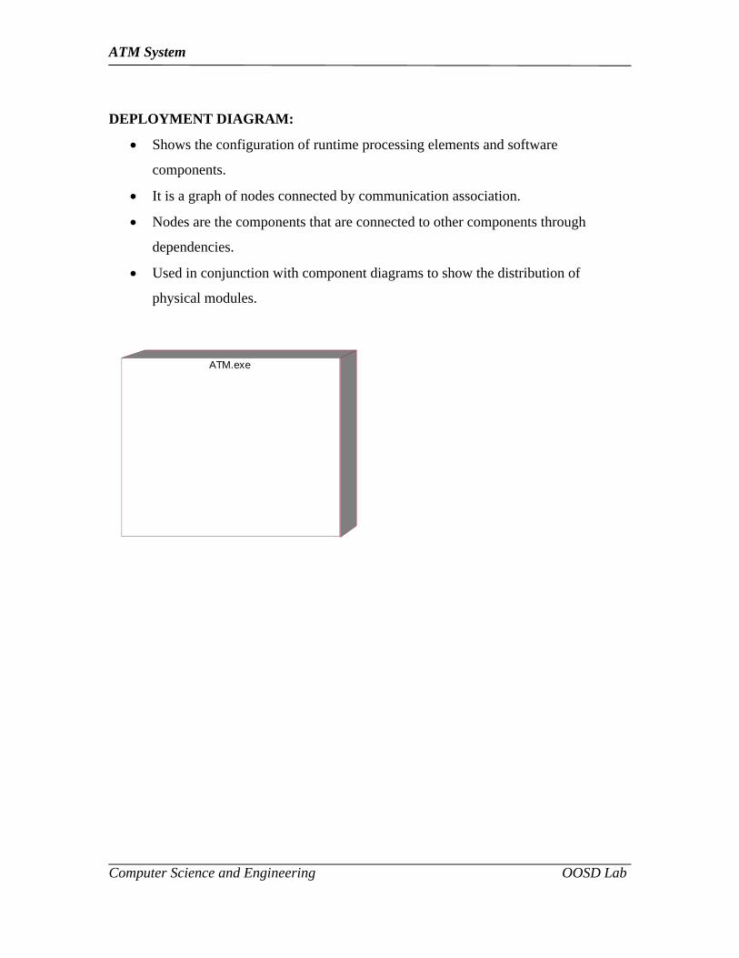
DEPLOYMENT DIAGRAM:
Shows the configuration of runtime processing elements and software
components.
It is a graph of nodes connected by communication association.
Nodes are the components that are connected to other components through
dependencies.
Used in conjunction with component diagrams to show the distribution of
physical modules.
ATM.exe

ATM System
Computer Science and Engineering OOSD Lab
RESULT
The Object Oriented Design for the project “ATM System” using Star UML
software design is completed successfully.
ATM System
Computer Science and Engineering OOSD Lab
Experiment No: 5
STUDY OF SOFTWARE TESTING PROCESS
Experiment Date:

ATM System
Computer Science and Engineering OOSD Lab
STUDY OF SOFTWARE TESTING PROCESS
AIM:
To study about the software testing process this includes various levels approaches and
types of testing.
5.1. OVERVIEW:
The importance of software testing to software quality can not be
overemphasized. Once source code has been generated, software must be tested to allow
errors to be identified and removed before delivery to the customer. While it is not
possible to remove every error in a large software package, the software engineer’s goal
is to remove as many as possible early in the software development cycle. It is important
to remember that testing can only find errors, it cannot prove that a program is bug free.
Two basic test techniques involve testing module input/output (black-box) and exercising
internal logic of software components (white-box). Formal technical reviews by
themselves can not find allow software defects, test data must also be used. For large
software projects, separate test teams may be used to develop and execute the set of test
cases used in testing. Testing must be planned and designed. The SEPA web site contains
the template for a generic test plan.
5.1.1. Software Testing Objectives:
Testing is the process of executing a program with the intent of finding
errors.
A good test case is one with a high probability of finding an as-yet
undiscovered error.
A successful test is one that discovers an as-yet-undiscovered error.
5.1.2. Software Testing Principles:
All tests should be traceable to customer requirements.
ATM System
Computer Science and Engineering OOSD Lab
Tests should be planned long before testing begins.
The Pareto principle (80% of all errors will likely be found in 20% of
the code) applies to software testing.
Testing should begin in the small and progress to the large.
Exhaustive testing is not possible.
To be most effective, testing should be conducted by an independent
third party.
5.1.3. Software Testability Checklist:
Operability (the better it works the more efficiently it can be tested)
Observably (what you see is what you test)
Controllability (the better software can be controlled the more testing
can be automated and optimized)
Decomposability (by controlling the scope of testing, the more quickly
problems can be isolated and retested intelligently)
Simplicity (the less there is to test, the more quickly we can test)
Stability (the fewer the changes, the fewer the disruptions to testing)
Understandability (the more information known, the smarter the
testing)
5.1.4. Good Test Attributes:
A good test has a high probability of finding an error.
A good test is not redundant.
A good test should be best of breed.
A good test should not be too simple or too complex.
5.1.5. Test Case Design Strategies:

ATM System
Computer Science and Engineering OOSD Lab
Black-box or behavioral testing (knowing the specified function a
product is to perform and demonstrating correct operation based solely
on its specification without regard for its internal logic)
White-box or glass-box testing (knowing the internal workings of a
product, tests are performed to check the workings of all independent
logic paths)
5.2. TESTING METHODS:
5.2.1. Basis Path Testing
White-box technique usually based on the program flow graph
The cyclomatic complexity of the program computed from its flow
graph using the formula V(G) = E – N + 2 or by counting the
conditional statements in the PDL representation and adding 1
Determine the basis set of linearly independent paths (the cardinality
of this set id the program cyclomatic complexity)
Prepare test cases that will force the execution of each path in the basis
set.
5.2.2 Control Structure Testing:
White-box techniques focusing on control structures present in the
software
Condition testing (e.g. branch testing) focuses on testing each decision
statement in a software module, it is important to ensure coverage of
all logical combinations of data that may be processed by the module
(a truth table may be helpful)

ATM System
Computer Science and Engineering OOSD Lab
Data flow testing selects test paths based according to the locations of
variable definitions and uses in the program (e.g. definition use chains)
Loop testing focuses on the validity of the program loop constructs
(i.e. simple loops, concatenated loops, nested loops, unstructured
loops), involves checking to ensure loops start and stop when they are
supposed to (unstructured loops should be redesigned whenever
possible)
5.2.3 Graph-based Testing Methods:
Black-box methods based on the nature of the relationships (links)
among the program objects (nodes), test cases are designed to traverse
the entire graph
Transaction flow testing (nodes represent steps in some transaction
and links represent logical connections between steps that need to be
validated)
Finite state modeling (nodes represent user observable states of the
software and links represent transitions between states)
Data flow modeling (nodes are data objects and links are
transformations from one data object to another)
Timing modeling (nodes are program objects and links are sequential
connections between these objects, link weights are required execution
times)
5.2.4. Comparison Testing:
Black-box testing for safety critical systems in which independently
developed implementations of redundant systems are tested for
conformance to specifications

ATM System
Computer Science and Engineering OOSD Lab
Often equivalence class partitioning is used to develop a common set
of test cases for each implementation
5.2.5. Orthogonal Array Testing:
Black-box technique that enables the design of a reasonably small set
of test cases that provide maximum test coverage
Focus is on categories of faulty logic likely to be present in the
software component (without examining the code)
Priorities for assessing tests using an orthogonal array
a. Detect and isolate all single mode faults
b. Detect all double mode faults
c. Multimode faults
5.3. UNIT TESTING:
Black box and white box testing.
Module interfaces are tested for proper information flow.
Local data are examined to ensure that integrity is maintained.
Boundary conditions are tested.
Basis path testing should be used.
All error handling paths should be tested.
Drivers and/or stubs need to be developed to test incomplete software.
5.4. INTEGRATION TESTING:
5.4.1. Top-down integration testing:
Main control module used as a test driver and stubs are substitutes for
components directly subordinate to it.
ATM System
Computer Science and Engineering OOSD Lab
Subordinate stubs are replaced one at a time with real
components(following the depth-first or breadth-first approach).
Tests are conducted as each component is integrated.
On completion of each set of tests and other stub is replaced with a
real component.
Regression testing may be used to ensure that new errors not
introduced.
5.4.2. Bottom-up integration testing:
Low level components are combined in clusters that perform a specific
software function.
A driver (control program) is written to coordinate test case input and
output.
The cluster is tested.
Drivers are removed and clusters are combined moving upward in the
program structure.
Regression testing (check for defects propagated to other modules by
changes made to existing program)
Representative sample of existing test cases is used to exercise all
software functions.
Additional test cases focusing software functions likely to be affected
by the change.
Tests cases that focus on the changed software components.
5.4.3. Smoke testing:
Software components already translated into code are integrated into a
build.
ATM System
Computer Science and Engineering OOSD Lab
A series of tests designed to expose errors that will keep the build from
performing its functions are created.
The build is integrated with the other builds and the entire product is
smoke tested daily (either top-down or bottom integration may be
used).
5.5. VALIDATION TESTING:
Ensure that each function or performance characteristic conforms to its
specification.
Deviations (deficiencies) must be negotiated with the customer to
establish a means for resolving the errors.
Configuration review or audit is used to ensure that all elements of the
software configuration have been properly developed, cataloged, and
documented to allow its support during its maintenance phase.
5.6. ACCEPTANCE TESTING:
Making sure the software works correctly for intended user in his or
her normal work environment.
Alpha test (version of the complete software is tested by customer
under the supervision of the developer at the developer’s site)
Beta test (version of the complete software is tested by customer at his
or her own site without the developer being present)
5.7. SYSTEM TESTING:
Recovery testing (checks the system’s ability to recover from failures)
Security testing (verifies that system protection mechanism prevent
improper penetration or data alteration)

ATM System
Computer Science and Engineering OOSD Lab
Stress testing (program is checked to see how well it deals with
abnormal resource demands – quantity, frequency, or volume)
Performance testing (designed to test the run-time performance of
software, especially real-time software)

ATM System
Computer Science and Engineering OOSD Lab
RESULT:
Study of software testing process has been completed and documented
successfully.

ATM System
Computer Science and Engineering OOSD Lab
Experiment No: 6
PROJECT PLAN FOR ATM SYSTEM
Experiment Date:

ATM System
Computer Science and Engineering OOSD Lab
PROJECT MANAGEMENT PLAN
AIM
The aim of the experiment is to prepare and document the project management plan
for the project “ATM SYSTEM
6.1 Introduction
6.1.1 Purpose
Project management plan describes the software life cycle of ATM SYSTEM based test
plan and resource plan of ATM SYSTEM.
6.2 Process Model
This ATM SYSTEM is developed by applying incremental model. The product is
designed, implemented, integrated and tested as series of incremental development
activities. The development activities consist of code pieces from various modules
interacting to provide a specific functional capability. This model delivers the quality
system and sub systems. The complete product is divided into several sub parts, and the
developers deliver the product in series of incremental development activities. It reduces
the traumatic effect of imposing a completely new ATM SYSTEM. From the financial
viewpoint, phased delivery does not require large outlay. In this model not necessary to
complete the product to get a return on investment. Instead, the client can stop
development of the product at any time.
Incremental model, the requirements, specifications, planning and architecture design
must all complete before implementation of the various sub systems. The client
requirements have been complete, the specification of the build draw up. When this has
been complete the specification team turns to the specification of the second build while
design team designs the first sub system. The various sub systems are constructed
parallel. Four increment in ATM SYSTEM.

ATM System
Computer Science and Engineering OOSD Lab
Fig: 6.1 Incremental Models for ATM SYSTEM
Requirements for ATM SYSTEM
ATM SYSTEM specification
ATM planning
ATM SYSTEMarchitectural design
Implementation
Incremental delivery
Operational mode of ATM System
Maintenance
Enter the username/password
Check the pin number and begin transaction
Perform the withdraw or fee pay operation
ATM System
Computer Science and Engineering OOSD Lab
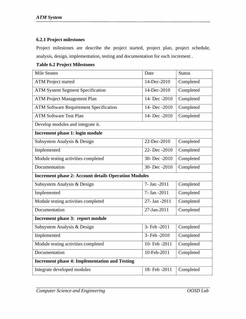
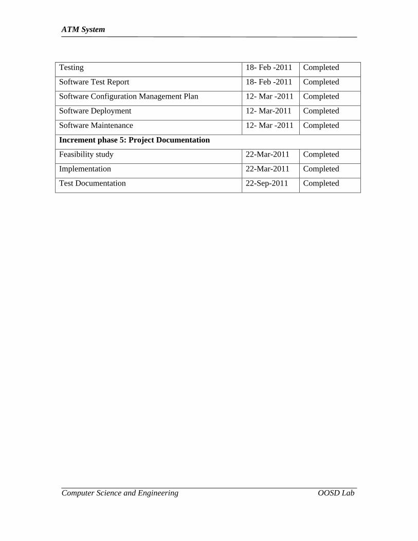
6.2.1 Project milestones
Project milestones are describe the project started, project plan, project schedule,
analysis, design, implementation, testing and documentation for each increment .
Table 6.2 Project Milestones
Mile Stones Date Status
ATM Project started 14-Dec-2010 Completed
ATM System Segment Specification 14-Dec-2010 Completed
ATM Project Management Plan 14- Dec -2010 Completed
ATM Software Requirement Specification 14- Dec -2010 Completed
ATM Software Test Plan 14- Dec -2010 Completed
Develop modules and integrate it.
Increment phase 1: login module
Subsystem Analysis & Design 22-Dec-2010 Completed
Implemented 22- Dec -2010 Completed
Module testing activities completed 30- Dec -2010 Completed
Documentation 30- Dec -2010 Completed
Increment phase 2: Account details Operation Modules
Subsystem Analysis & Design 7- Jan -2011 Completed
Implemented 7- Jan -2011 Completed
Module testing activities completed 27- Jan -2011 Completed
Documentation 27-Jan-2011 Completed
Increment phase 3: report module
Subsystem Analysis & Design 3- Feb -2011 Completed
Implemented 3- Feb -2010 Completed
Module testing activities completed 10- Feb -2011 Completed
Documentation 10-Feb-2011 Completed
Increment phase 4: Implementation and Testing
Integrate developed modules 18- Feb -2011 Completed
ATM System
Computer Science and Engineering OOSD Lab
Testing 18- Feb -2011 Completed
Software Test Report 18- Feb -2011 Completed
Software Configuration Management Plan 12- Mar -2011 Completed
Software Deployment 12- Mar-2011 Completed
Software Maintenance 12- Mar -2011 Completed
Increment phase 5: Project Documentation
Feasibility study 22-Mar-2011 Completed
Implementation 22-Mar-2011 Completed
Test Documentation 22-Sep-2011 Completed

ATM System
Computer Science and Engineering OOSD Lab
RESULT:
The Project Plan for the project “ATM System” has been analyzed and documented
successfully.
ATM System
Computer Science and Engineering OOSD Lab
Experiment No: 7
SYSTEM ANALYSIS SPECIFICATION FOR ATM SYSTEM
Experiment Date:
ATM System
Computer Science and Engineering OOSD Lab
SYSTEM ANALYSIS SPECIFICATION FOR ATM SYSTEM
AIM: Aim of the experiment is to prepare and document the software analysis specification for “Atm System”.
7.0 INTRODUCTION
7.1 Purpose
This document is used to capture the output of system level requirements analysis of
Atm System. This document clearly describes the functional and non functional
requirements of the system, and overall development of the Atm System. It specifies a
high level requirements specification model in terms of UML methodology.
7.2 Scope
Scope of the Atm System is to reduce the answering time and generating the report.
7.3 References:
(i) IEEE Recommended practice for SRS IEEE Standard 830-1993
(ii) “Object Oriented Analysis and design” Ali Bahrami, Object Oriented System
Development, using UML, McGraw –Hill international Edition, 1999
7.3.1 Government Documents
DOD 2167A Defense Standard Software Development
7.3.2 Non Government Documents
Ali Bahrami, Object Oriented System Development, using UML, McGraw –Hill
international Edition, 1999
Software Engineering Book
7.4 System Overview
The main problem addressed is to automate the quiz in companies. The ultimate aim
to reduce the manpower and it is computerized.
2 Functional Requirements
Use case for Atm System

ATM System
Computer Science and Engineering OOSD Lab
Fig: 7.1Use Case for Atm System.
Actors
Participant
System
System Administrator
Organizer
Use Case
Create
Delete
Update
Analyze

ATM System
Computer Science and Engineering OOSD Lab
1 Scenarios:
Scenario starts
when
Actor Trace Action Output
organizer enters the question in the user database
Administrator Create the
database which
contains the
student details
Verifies the
database
Displays the
database
Participant Details of the
Question
Verifies the
Answer details
Displays the
database which
contains the
Answer details
about the
Question.
System Details of the
Question
Verifies the
Answer
Checks the
marks of each
Question
2 Non-Functional Requirements
Usability (ATM System)
The Atm System is used to attend the online test in a computerized manner.
3 Metrics for system Analysis and Specification
Metrics are units of measurement of Atm System. The term “metrics” is also
frequently used to mean a set of measurement taken on a particular item or process of
Atm System.
Software engineering metrics are units of measurement that are used to
characterize:
Software engineering Products for Atm System, e.g. designs, source code and
test cases.
ATM System
Computer Science and Engineering OOSD Lab
Software engineering Processes for Atm System, e.g. the activities of analysis,
designing, and coding.
Software engineering People for Atm System, e.g. the efficiency of an individual
tester, or the productivity of an individual designer. To measure the Atm System
for each increment of Atm System.
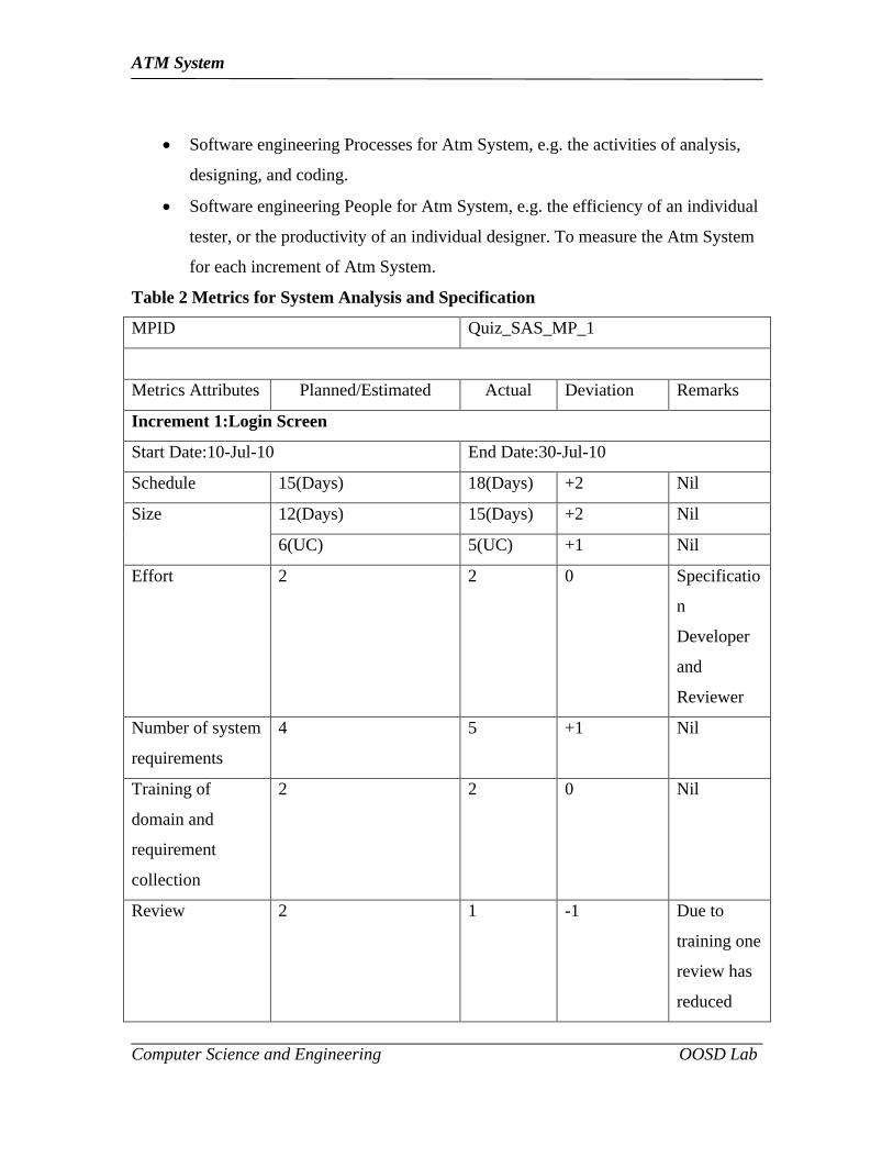
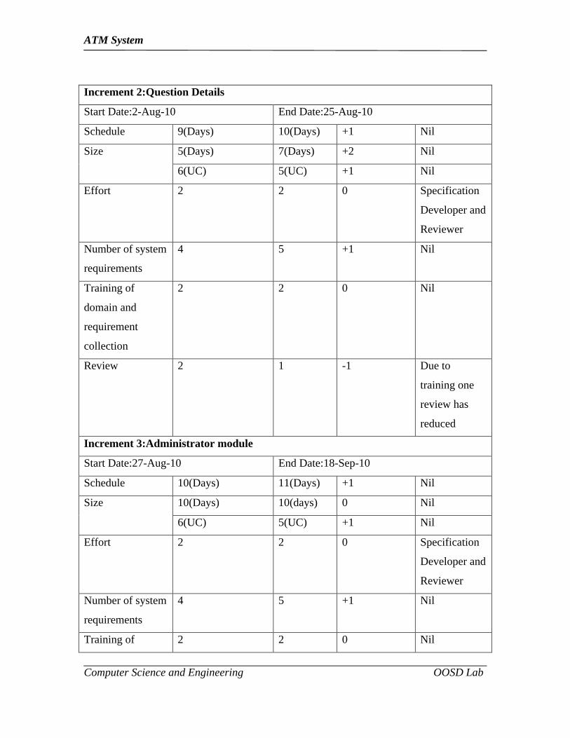
Table 2 Metrics for System Analysis and Specification
MPID Quiz_SAS_MP_1
Metrics Attributes Planned/Estimated Actual Deviation Remarks
Increment 1:Login Screen
Start Date:10-Jul-10 End Date:30-Jul-10
Schedule 15(Days) 18(Days) +2 Nil
Size 12(Days) 15(Days) +2 Nil
6(UC) 5(UC) +1 Nil
Effort 2 2 0 Specificatio
n
Developer
and
Reviewer
Number of system
requirements
4 5 +1 Nil
Training of
domain and
requirement
collection
2 2 0 Nil
Review 2 1 -1 Due to
training one
review has
reduced
ATM System
Computer Science and Engineering OOSD Lab
Increment 2:Question Details
Start Date:2-Aug-10 End Date:25-Aug-10
Schedule 9(Days) 10(Days) +1 Nil
Size 5(Days) 7(Days) +2 Nil
6(UC) 5(UC) +1 Nil
Effort 2 2 0 Specification
Developer and
Reviewer
Number of system
requirements
4 5 +1 Nil
Training of
domain and
requirement
collection
2 2 0 Nil
Review 2 1 -1 Due to
training one
review has
reduced
Increment 3:Administrator module
Start Date:27-Aug-10 End Date:18-Sep-10
Schedule 10(Days) 11(Days) +1 Nil
Size 10(Days) 10(days) 0 Nil
6(UC) 5(UC) +1 Nil
Effort 2 2 0 Specification
Developer and
Reviewer
Number of system
requirements
4 5 +1 Nil
Training of 2 2 0 Nil
ATM System
Computer Science and Engineering OOSD Lab
domain and
requirement
collection
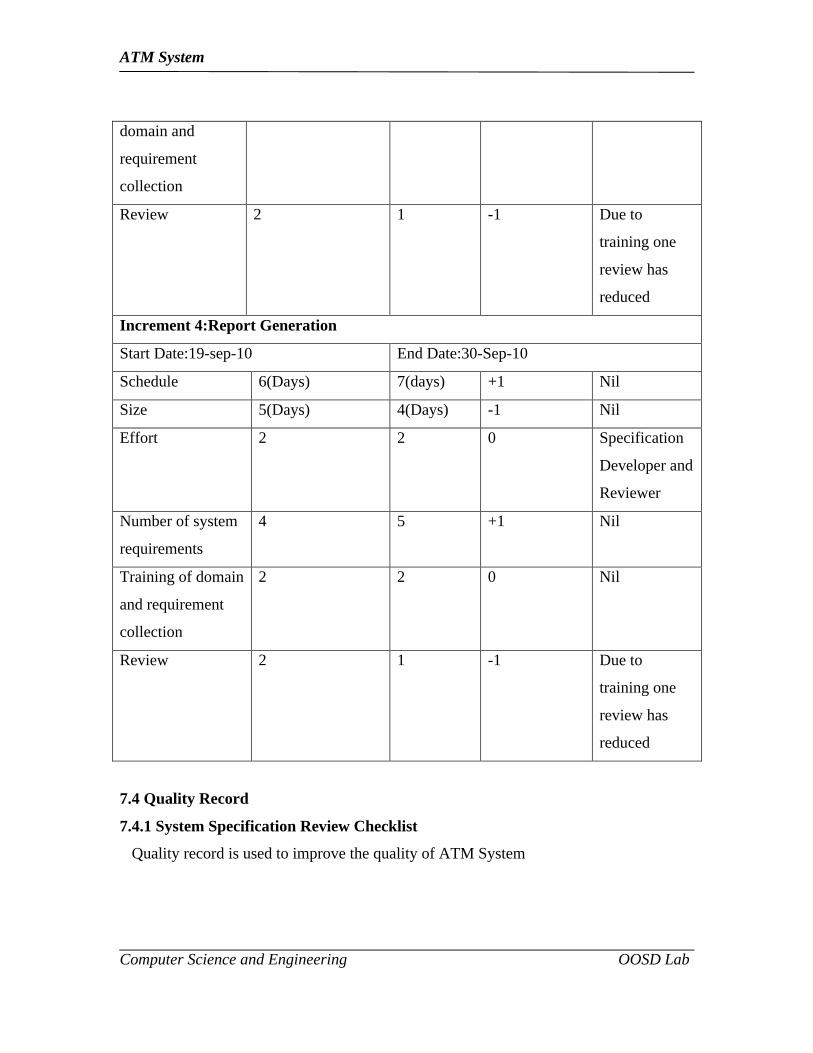
Review 2 1 -1 Due to
training one
review has
reduced
Increment 4:Report Generation
Start Date:19-sep-10 End Date:30-Sep-10
Schedule 6(Days) 7(days) +1 Nil
Size 5(Days) 4(Days) -1 Nil
Effort 2 2 0 Specification
Developer and
Reviewer
Number of system
requirements
4 5 +1 Nil
Training of domain
and requirement
collection
2 2 0 Nil
Review 2 1 -1 Due to
training one
review has
reduced
7.4 Quality Record
7.4.1 System Specification Review Checklist
Quality record is used to improve the quality of ATM System
ATM System
Computer Science and Engineering OOSD Lab
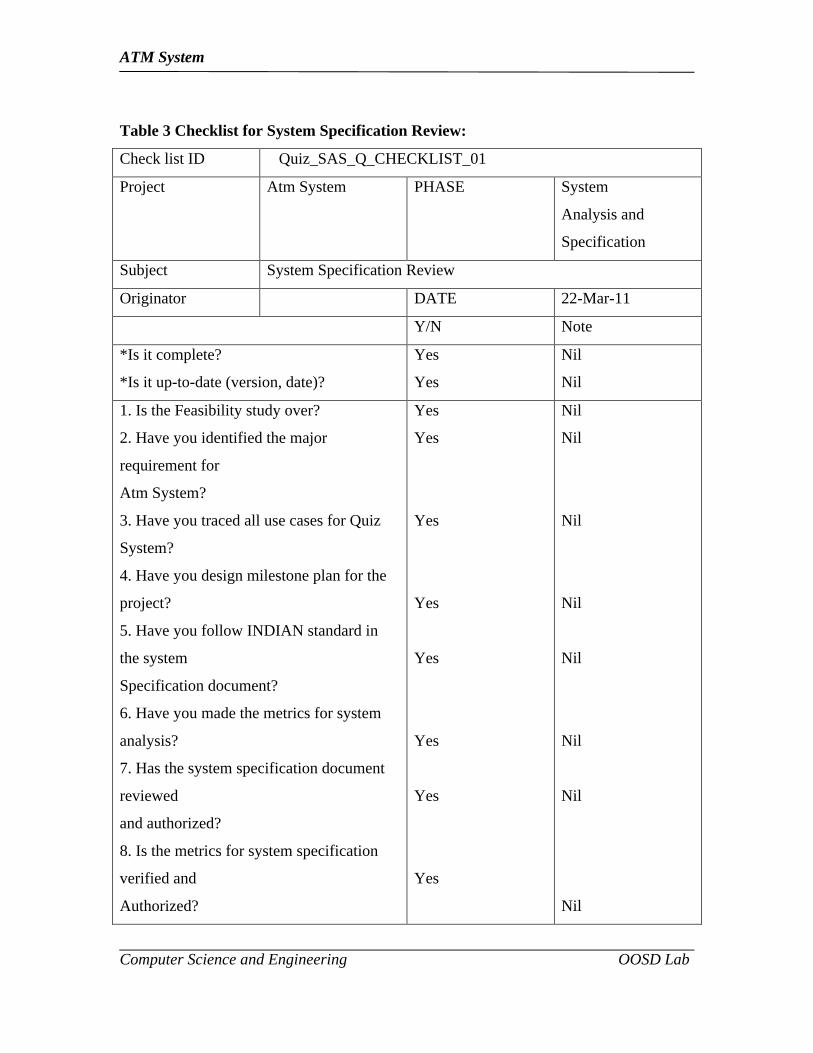
Table 3 Checklist for System Specification Review:
Check list ID Quiz_SAS_Q_CHECKLIST_01
Project Atm System PHASE System
Analysis and
Specification
Subject System Specification Review
Originator DATE 22-Mar-11
Y/N Note
*Is it complete?
*Is it up-to-date (version, date)?
Yes
Yes
Nil
Nil
1. Is the Feasibility study over?
2. Have you identified the major
requirement for
Atm System?
3. Have you traced all use cases for Quiz
System?
4. Have you design milestone plan for the
project?
5. Have you follow INDIAN standard in
the system
Specification document?
6. Have you made the metrics for system
analysis?
7. Has the system specification document
reviewed
and authorized?
8. Is the metrics for system specification
verified and
Authorized?
Yes
Yes
Yes
Yes
Yes
Yes
Yes
Yes
Nil
Nil
Nil
Nil
Nil
Nil
Nil
Nil
ATM System
Computer Science and Engineering OOSD Lab
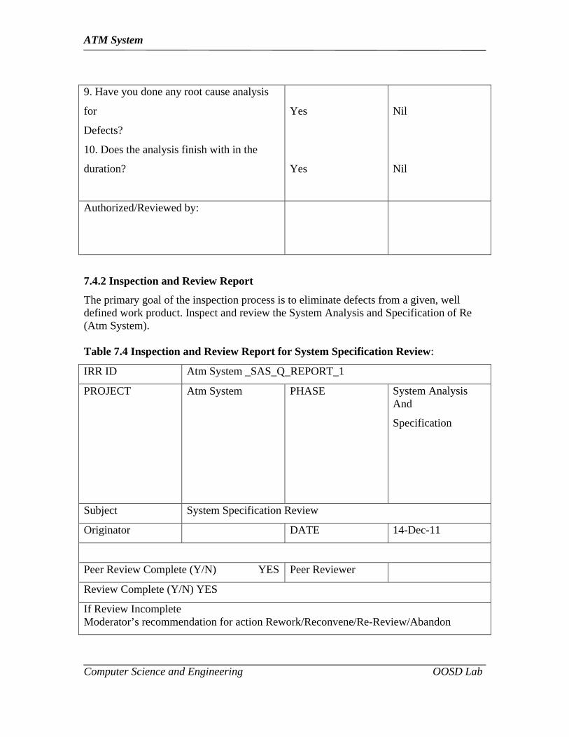
9. Have you done any root cause analysis
for
Defects?
10. Does the analysis finish with in the
duration?
Yes
Yes
Nil
Nil
Authorized/Reviewed by:
7.4.2 Inspection and Review Report
The primary goal of the inspection process is to eliminate defects from a given, well defined work product. Inspect and review the System Analysis and Specification of Re (Atm System).
Table 7.4 Inspection and Review Report for System Specification Review:
IRR ID Atm System _SAS_Q_REPORT_1
PROJECT Atm System PHASE System AnalysisAnd
Specification
Subject System Specification Review
Originator DATE 14-Dec-11
Peer Review Complete (Y/N) YES Peer Reviewer
Review Complete (Y/N) YES
If Review IncompleteModerator’s recommendation for action Rework/Reconvene/Re-Review/Abandon
ATM System
Computer Science and Engineering OOSD Lab
Commands: Inspection and Review Report for System Specification Review is verifiedCorrectly.
Signed:
Project Manager’s Decision: Inspection and Review Report for System SpecificationReview is verified correctly.
Signed.
ATM System
Computer Science and Engineering OOSD Lab
RESULT
The Software Analysis Specification for the project “ATM System” has been
analyzed and documented successfully.

ATM System
Computer Science and Engineering OOSD Lab
Experiment No: 8
TEST PLAN FOR THE ATM SYSTEM
Experiment Date:
ATM System
Computer Science and Engineering OOSD Lab
TEST PLAN FOR THE ATM SYSTEM
AIM: Aim of the experiment is to prepare and document the test plan for the project ATM SYSTEM.
8.1 Introduction
8.1.1 Purpose
The main purpose of this document is to achieve the 100% functionally correct system
and to ensure all functional and design requirements are implemented as specified in the
documentation. It also provides a procedure, identified of the documentation process and
test methods for system level testing.
8.2 Test Identification
8.2.1.1 Test Item
All the required items will be tested during the system test.
The following documents will provide the basis for defining correct operation.
Software requirements
Software design description.
8.2.1.2 Registration process
This process is used for the user to register into the system and the entire registration is
stored in the Administrator.
8.2.1.3 Account generation
The account process is one in which the Account details are being generated and
activated.
8.2.1.1.3 Report generation.
The reports of the answer details are generated.
Test GUI display
Test interface with display unit.
8.3 Features to be tested
The following functionalities of the Atm System to be tested for functional correctness
Enters the pin no.

ATM System
Computer Science and Engineering OOSD Lab
View the process
Perform operations.
Choose the options.
Withdraw or balance enquiry
Generate the result.
8.4 Test Approach
8.4.1 Test Levels
Atm System is to be tested in different levels like unit, integration, system level.
All programs like getting the request, Analysis the request are to be tested at unit
level by developer themselves.
All modules like Registration module, question and answer module, report
module are to be tested individually.
The whole Atm System is tested after integration i.e., Integration testing, the main
emphasis is the functionality and the integration.
The entire system is tested by stress testing for find out the whether system is
properly functioning in critical environment.
The acceptance testing is find out the Atm System achieve the corresponding goal
or not.
8.4.2 Test Classes
8.4.2.1 User Interface Testing for Atm System
User interface testing verifies a user’s interaction with the software. The goal of UI
testing is to ensure that the user interface provides the user with the appropriate access
and navigation through the functions of the Atm System. In addition, UI testing ensure
that the objects within the UI functions as expected and conform to corporate or industry
standards.
Test Objective
Verify following:

ATM System
Computer Science and Engineering OOSD Lab
Navigation through the Quiz application properly reflects business functions and
requirements, including window-to-window, field-to-field and use of access
methods (tab keys, mouse movements, accelerator keys).
Window objects and characteristics, such as menus, size position, state and focus
conform to GUI.
Technique
Create or modify test for each window to verify proper navigation and object states for
each application window and objects.
Completion Criteria
Each window successfully verified to consistent with benchmark version or within
acceptable standard.
8.4.2.2 Load Testing of Atm System
The goal of load testing is to determine and ensure that the system functions properly
beyond the expected maximum workload. Additionally, load testing the performance
characteristics are vary from line to line depend on the speed of the line.
Test Objective
Verify performance behavior time for designated functions or business cases under
varying workload conditions.i.e. To test whether the communication interface and
processing model are properly working in huge network environment
Completion Criteria
Many no of active systems or huge network environment: successful completion of test
without any failures within acceptable time allocation.
8.4.2.3 Security Testing
The goal of Security Testing is to ensure system security capability.
If the system is compromised with attackers then it should reflect what are the activities
made by attacker like tools, techniques etc. The processing module captures all the
information from Atm System.
8.4.2.4 Recovery Testing
ATM System
Computer Science and Engineering OOSD Lab
Recovery will be tested by halting the machine during stand alone time and then
following recovery procedures.
8.4.2.5 Performance Testing
Performance will be evaluated against the performance requirements by measuring the
run times of several jobs using production data volumes.
8.4.2.6 Regression Testing
It is assumed that several iterations of the system test will be done in order to test
program modifications made during the system test period. A regression test will be
performed for each new version of the system to detect unexpected impact resulting from
modifications.
8.4.2.7 General test conditions
General test conditions describe conditions that apply to all of the test or to a group of
tests in Atm System. Each test shall include nominal, maximum, minimum values,
execution size and time shall be measured for each Atm System. Include shall be
statement of the extent of testing to be performed and rational for the extent selected. The
extend of testing shall be expressed as a percentage of some well defined total quality,
such as the number of samples of discrete operating conditions or values, or other
sampling approach. Also included some approaches to be followed for
retesting/regression testing.
8.4.2.8 Data recording, reduction and analysis
Data recording, reduction and analysis procedures to be used during and after the test’
identified in this Atm System test plan. These procedures shall include, as applicable,
manual, automatic, and semi automatic techniques for recording test results, manipulating
the raw results into a form suitable for evaluation, and retaining of data reduction and
analysis. To record all test level and test classes, if any faults is there to record that, and
also give the solution to reduce that faults.
8.4.3 Planned Test
8.4.3.1 Basic function test

ATM System
Computer Science and Engineering OOSD Lab
Enter the user name.
Enter the password.
Choose the question type.
Write the exam.
Get the result
8.5 Item pass/ fail criteria
Pass criteria Atm System module outputs should be expected outputs.
Fail criteria not meet the expected outputs.
8.6 Test deliverables
The following documents will be generated by system test group and will be delivered to
the configuration management team after its completion.
Test documentation
System Test Plan
System Test Design specification
System Test Case Specification
System Test Procedures Specification
System Test Logs
System Test Incident Report Log
System Test Incident Reports
System Test Summary Report
Test data
1. Copies of all data entry and inquiry screens and the reply screens are to be attached to
the related test case document.
2. Copies of the input and output test files should be delivered to the configuration
management team.
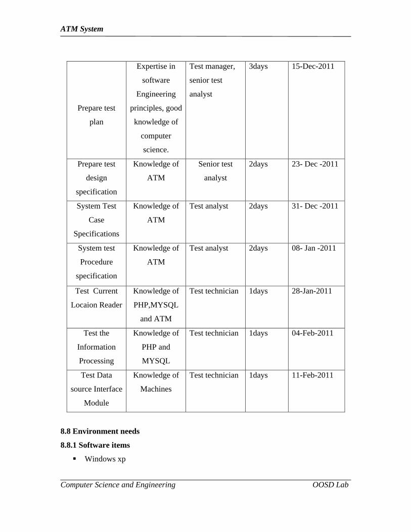
8.7 Testing Tasks
Table 8.1 Testing Tasks
Task Special skills Responsibility Effort Finish date
ATM System
Computer Science and Engineering OOSD Lab
Prepare test
plan
Expertise in
software
Engineering
principles, good
knowledge of
computer
science.
Test manager,
senior test
analyst
3days 15-Dec-2011
Prepare test
design
specification
Knowledge of
ATM
Senior test
analyst
2days 23- Dec -2011
System Test
Case
Specifications
Knowledge of
ATM
Test analyst 2days 31- Dec -2011
System test
Procedure
specification
Knowledge of
ATM
Test analyst 2days 08- Jan -2011
Test Current
Locaion Reader
Knowledge of
PHP,MYSQL
and ATM
Test technician 1days 28-Jan-2011
Test the
Information
Processing
Knowledge of
PHP and
MYSQL
Test technician 1days 04-Feb-2011
Test Data
source Interface
Module
Knowledge of
Machines
Test technician 1days 11-Feb-2011
8.8 Environment needs
8.8.1 Software items
Windows xp
ATM System
Computer Science and Engineering OOSD Lab
PHP
MYSQL
Rational Rose
8.8.2 Hardware and Firmware Items
PC with P4 processor, 256 RAM, 40 GB HDD
8.8.3 Proprietary nature, acquire rights and licensing
Rational Rose is used to design and developed the software.
PHP is support to develop the software.
MY-SQL is used to compile.
8.9 Responsibility
Project Manager- Responsible for Project schedules and overall and the success of the
project
Test Leader- verify the test documents.
Tester Responsible for performing the actual system testing.
8.10 Staffing and training needs
Test manager -1
Senior Analyst -1
Test Analyst -2
Test Technician -1
Training
Skill needs
Basic knowledge of PHP
Basic knowledge of MYSQL
Strong knowledge in software Engineering principles
8.11 Schedule
System Test -- (5 hours)
Performance Test -- (7 hours)
Document Test -- (3 hours)
Unit Test -- (7 hours)
ATM System
Computer Science and Engineering OOSD Lab
User Acceptance Test -- (9 hours)
8.11 Risk and Contingencies
8.11.1 Schedule
The schedule for each phase is very aggressive and could affect testing. A slip in the
schedule in one of the other phase could result in a subsequent slip in the test phase. If the
testing schedule is significantly impacted by system failure, the project manager has
agreed to assign a full time person to the test team to co debugging.
8.11.2 Personnel
If one test analyst/technician is not available for testing, then the test manager has agreed
to identify a second analyst/technician. Due to the schedule, it’s very important to have
experienced testers on this project. Unexpected turnovers can impact the schedule. If
attrition does happen, all efforts must to replace the experienced individual.
8.11.3 Requirements
The test plan and test schedule are based on the current requirements document. Any
change to the requirements could affect the test schedule. Changes should be approved by
the project manager.
8.11.4 Technical
The hardware problems impact system availability during the day, then the test group will
schedule their activities during the evening. The first production runs of the Atm System
must be checked out in detail before the Atm System processes are distributed, and any
checks in error must be corrected by manually.
ATM System
Computer Science and Engineering OOSD Lab
RESULT:
The Test Plan for the project “ATM System” has been analyzed and documented
successfully.
ATM System
Computer Science and Engineering OOSD Lab
Experiment No: 1
PROBLEM STATEMENT FOR THE ATM SYSTEM
Experiment Date:

ATM System
Computer Science and Engineering OOSD Lab
AIM: Aim of the experiment is to prepare Problem Statement for the project ATM SYSTEM.
PROCEDURE:
1. ATM machine is mainly used for withdrawal money from any time.
2. In emergency case, we use only ATM machine system.
3. It has some additional feautures also such as Transfer funds, change PIN, checking balance enquiry and so on.
4. After getting cash, it provides confirmation receipt.
5. Using this ATM system, we save our time.
6. If we use ATM machine for withdrawal money, some procedural are follows,
Insert the ATM card to the machine, then the machine verify the card number.
Then it activate user accounts and it display the welcome screen.
Then it ask our four digits PIN no. If our PIN no correct means, it should display the next information such as cash withdraw, mini statement, etc. otherwise it should display PIN no not valid.
We select cash withdraw, and type how much amount we want.
If our amount exceeds our account balance, then it should display not enough balance in your account.
Then from cash dispensher, user collect the cash and receipt.
Finally we eject the card.
ATM System
Computer Science and Engineering OOSD Lab
RESULT:
The Problem Statement for the project “ATM System” has been Prepared
successfully.
ATM System
Computer Science and Engineering OOSD Lab
Experiment No: 9
IMPLEMENTATION FOR THE ATM SYSTEM
Experiment Date:

ATM System
Computer Science and Engineering OOSD Lab
AIM:
To prepare an implementation For the project “ATM SYSTEM”
PROCEDURE:
//WELCOME SCREEN
Data1.Refreshsd = TrueDim s As Strings = Text1.TextIf Data1.Recordset.EOF ThenMsgBox "Invalid Card No.", vbCritical, "Sorry! Plz Try Later"Text1.SetFocusText1.SelStart = 0Text1.SelLength = Len(Text1.Text)Exit SubElse Form2.Show Me.Hide SendKeys "{home}+{end}"End IfEnd Sub
Private Sub Command2_Click()EndEnd Sub
Private Sub Command3_Click()EndEnd Sub
Private Sub Command4_Click(Index As Integer)Text1.Text = Text1.Text + Command4(Index).CaptionEnd Sub
Private Sub Command5_Click()Text1.Text = ""End Sub
ATM System
Computer Science and Engineering OOSD Lab
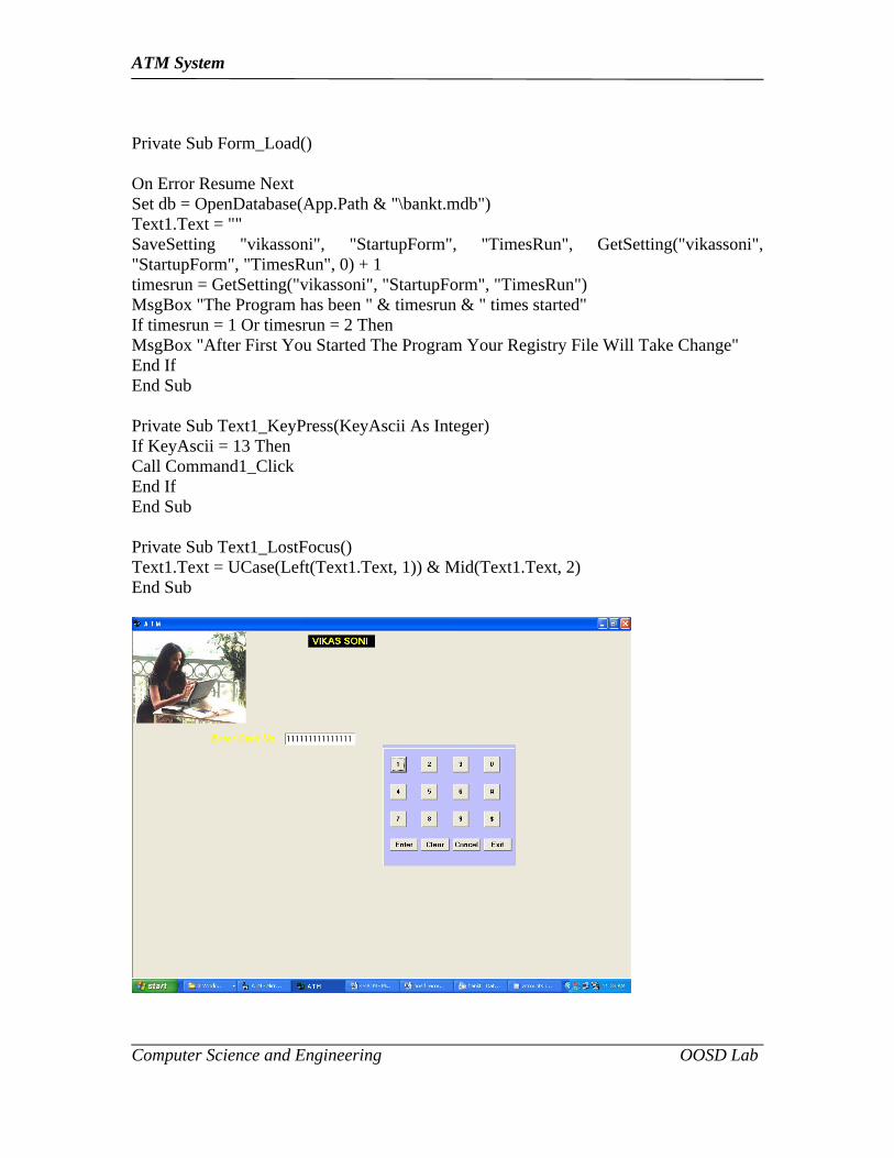
Private Sub Form_Load()
On Error Resume NextSet db = OpenDatabase(App.Path & "\bankt.mdb")Text1.Text = ""SaveSetting "vikassoni", "StartupForm", "TimesRun", GetSetting("vikassoni", "StartupForm", "TimesRun", 0) + 1timesrun = GetSetting("vikassoni", "StartupForm", "TimesRun")MsgBox "The Program has been " & timesrun & " times started"If timesrun = 1 Or timesrun = 2 ThenMsgBox "After First You Started The Program Your Registry File Will Take Change"End IfEnd Sub
Private Sub Text1_KeyPress(KeyAscii As Integer)If KeyAscii = 13 ThenCall Command1_ClickEnd IfEnd Sub
Private Sub Text1_LostFocus()Text1.Text = UCase(Left(Text1.Text, 1)) & Mid(Text1.Text, 2)End Sub
ATM System
Computer Science and Engineering OOSD Lab
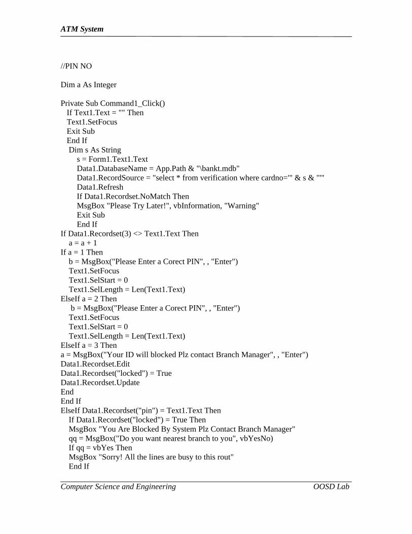
//PIN NO
Dim a As Integer
Private Sub Command1_Click() If Text1.Text = "" Then Text1.SetFocus Exit Sub End If Dim s As String s = Form1.Text1.Text Data1.DatabaseName = App.Path & "\bankt.mdb" Data1.RecordSource = "select * from verification where cardno='" & s & "'" Data1.Refresh If Data1.Recordset.NoMatch Then MsgBox "Please Try Later!", vbInformation, "Warning" Exit Sub End IfIf Data1.Recordset(3) <> Text1.Text Then a = a + 1If a = 1 Then b = MsgBox("Please Enter a Corect PIN", , "Enter") Text1.SetFocus Text1.SelStart = 0 Text1.SelLength = Len(Text1.Text)ElseIf a = 2 Then b = MsgBox("Please Enter a Corect PIN", , "Enter") Text1.SetFocus Text1.SelStart = 0 Text1.SelLength = Len(Text1.Text)ElseIf a = 3 Thena = MsgBox("Your ID will blocked Plz contact Branch Manager", , "Enter")Data1.Recordset.EditData1.Recordset("locked") = TrueData1.Recordset.UpdateEndEnd IfElseIf Data1.Recordset("pin") = Text1.Text Then If Data1.Recordset("locked") = True Then MsgBox "You Are Blocked By System Plz Contact Branch Manager" qq = MsgBox("Do you want nearest branch to you", vbYesNo) If qq = vbYes Then MsgBox "Sorry! All the lines are busy to this rout" End If
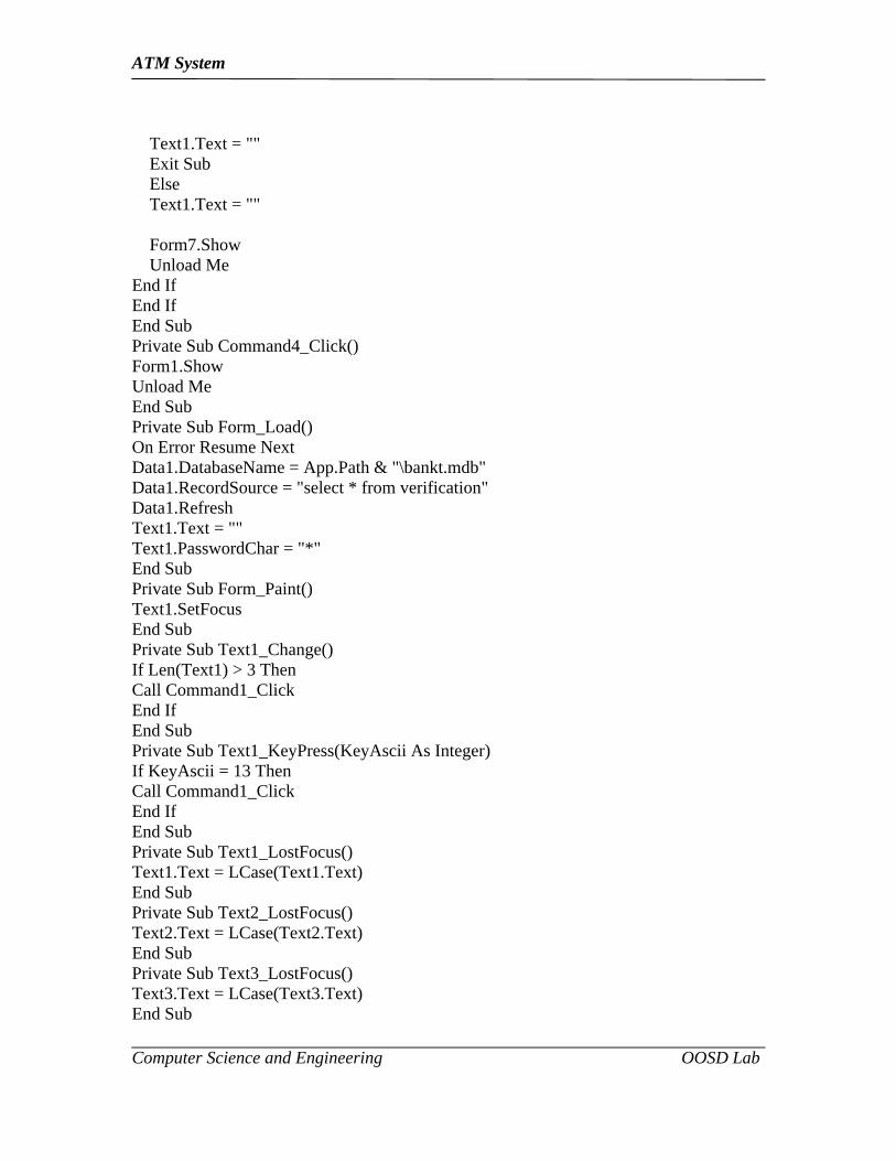
ATM System
Computer Science and Engineering OOSD Lab
Text1.Text = "" Exit Sub Else Text1.Text = "" Form7.Show Unload MeEnd IfEnd IfEnd SubPrivate Sub Command4_Click()Form1.ShowUnload MeEnd SubPrivate Sub Form_Load()On Error Resume NextData1.DatabaseName = App.Path & "\bankt.mdb"Data1.RecordSource = "select * from verification"Data1.RefreshText1.Text = ""Text1.PasswordChar = "*"End SubPrivate Sub Form_Paint()Text1.SetFocusEnd SubPrivate Sub Text1_Change()If Len(Text1) > 3 ThenCall Command1_ClickEnd IfEnd SubPrivate Sub Text1_KeyPress(KeyAscii As Integer)If KeyAscii = 13 ThenCall Command1_ClickEnd IfEnd SubPrivate Sub Text1_LostFocus()Text1.Text = LCase(Text1.Text)End SubPrivate Sub Text2_LostFocus()Text2.Text = LCase(Text2.Text)End SubPrivate Sub Text3_LostFocus()Text3.Text = LCase(Text3.Text)End Sub

ATM System
Computer Science and Engineering OOSD Lab
//MAIN MENUPrivate Sub Command1_Click()Form6.ShowUnload MeEnd Sub
Private Sub Command10_Click()Load Form4Form4.ShowUnload MeEnd Sub
Private Sub Command2_Click()Me.HideReport.ShowEnd Sub
Private Sub Command3_Click()Form3.ShowUnload MeEnd Sub
ATM System
Computer Science and Engineering OOSD Lab
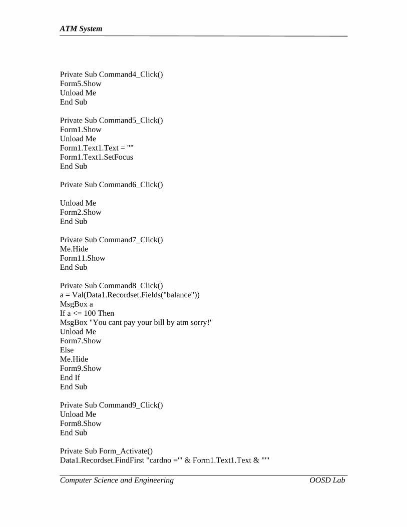
Private Sub Command4_Click()Form5.ShowUnload MeEnd Sub
Private Sub Command5_Click()Form1.ShowUnload MeForm1.Text1.Text = ""Form1.Text1.SetFocusEnd Sub
Private Sub Command6_Click()
Unload MeForm2.ShowEnd Sub
Private Sub Command7_Click()Me.HideForm11.ShowEnd Sub
Private Sub Command8_Click()a = Val(Data1.Recordset.Fields("balance"))MsgBox aIf a <= 100 ThenMsgBox "You cant pay your bill by atm sorry!"Unload MeForm7.ShowElseMe.HideForm9.ShowEnd IfEnd Sub
Private Sub Command9_Click()Unload MeForm8.ShowEnd Sub
Private Sub Form_Activate()Data1.Recordset.FindFirst "cardno ='" & Form1.Text1.Text & "'"

ATM System
Computer Science and Engineering OOSD Lab
End Sub
Private Sub Form_Load()Data1.DatabaseName = App.Path & "\bankt.mdb"Data1.RecordSource = "accounts"Data1.Refresh
End Sub
Private Sub Form_Paint()Command1.SetFocusEnd Sub
//CASH WITHDRAW
Private Sub Command1_Click()Dim s, d As DoubleIf Text1.Text = "" ThenText1.SetFocusMsgBox "Please Enter Amount Rupees", vbInformation, "Warning"Exit SubEnd IfData1.Recordset.MoveFirst
ATM System
Computer Science and Engineering OOSD Lab
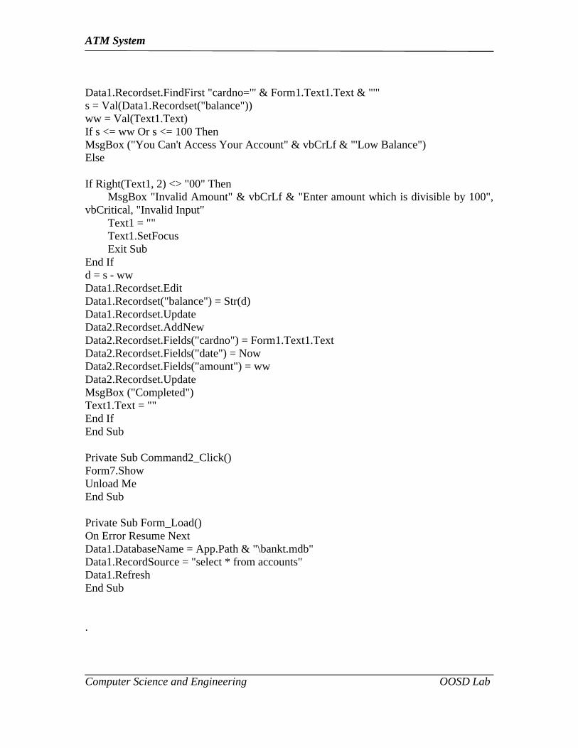
Data1.Recordset.FindFirst "cardno='" & Form1.Text1.Text & "'"s = Val(Data1.Recordset("balance"))ww = Val(Text1.Text)If s <= ww Or s <= 100 ThenMsgBox ("You Can't Access Your Account" & vbCrLf & "'Low Balance")Else
If Right(Text1, 2) <> "00" Then MsgBox "Invalid Amount" & vbCrLf & "Enter amount which is divisible by 100", vbCritical, "Invalid Input" Text1 = "" Text1.SetFocus Exit SubEnd Ifd = s - wwData1.Recordset.EditData1.Recordset("balance") = Str(d)Data1.Recordset.UpdateData2.Recordset.AddNewData2.Recordset.Fields("cardno") = Form1.Text1.TextData2.Recordset.Fields("date") = NowData2.Recordset.Fields("amount") = wwData2.Recordset.UpdateMsgBox ("Completed")Text1.Text = ""End IfEnd Sub
Private Sub Command2_Click()Form7.ShowUnload MeEnd Sub
Private Sub Form_Load()On Error Resume NextData1.DatabaseName = App.Path & "\bankt.mdb"Data1.RecordSource = "select * from accounts"Data1.RefreshEnd Sub
.
ATM System
Computer Science and Engineering OOSD Lab
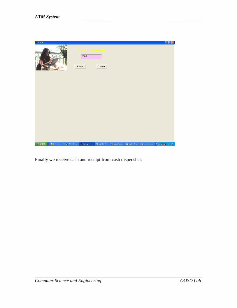
Finally we receive cash and receipt from cash dispensher.
ATM System
Computer Science and Engineering OOSD Lab
RESULT:
Thus the above Atm System has been Implemented Successfully.