Embed Size (px)
Citation preview

Lyu et al. BioMedical Engineering OnLine 2013, 12:63http://www.biomedical-engineering-online.com/content/12/1/63
RESEARCH Open Access
Experience-based virtual training system for kneearthroscopic inspectionShaw-Ruey Lyu1†, Yen-Kun Lin2*†, Shian-Tang Huang2† and Hong-Tzong Yau2†
* Correspondence:[email protected]†Equal contributors2Department of MechanicalEngineering, National Chung ChengUniversity, Chia-yi, Taiwan, ROCFull list of author information isavailable at the end of the article
Abstract
Background: Arthroscopic surgical training is inherently difficult due to limitedvisibility, reduced motion freedom and non-intuitive hand-eye coordination.Traditional training methods as well as virtual reality approach lack the directguidance of an experienced physician.
Methods: This paper presents an experience-based arthroscopic training simulatorthat integrates motion tracking with a haptic device to record and reproduce thecomplex trajectory of an arthroscopic inspection procedure. Optimal arthroscopicoperations depend on much practice because the knee joint space is narrow andthe anatomic structures are complex. The trajectory of the arthroscope from theexperienced surgeon can be captured during the clinical treatment. Then a hapticdevice is used to guide the trainees in the virtual environment to follow thetrajectory.
Results: In this paper, an experiment for the eight subjects’ performance ofarthroscopic inspection on the same simulator was done with and without the forceguidance. The experiment reveals that most subjects’ performances are better afterthey repeated the same inspection five times. Furthermore, most subjects’performances with the force guidance are better than those without the forceguidance. In the experiment, the average error with the force guidance is 33.01%lower than that without the force guidance. The operation time with the forceguidance is 14.95% less than that without the force guidance.
Conclusions: We develop a novel virtual knee arthroscopic training system withvirtual and haptic guidance. Compared to traditional VR training system that only hasa single play-script based on a virtual model, the proposed system can track andreproduce real-life arthroscopic procedures and create a useful training database.From our experiment, the force guidance can efficiently shorten the learning curveof novice trainees. Through such system, novice trainees can efficiently developrequired surgical skills by the virtual and haptic guidance from an experiencedsurgeon.
BackgroundIn recent years, arthroscopy has played a significant role for orthopaedic surgeons to
perform minimally invasive surgery (MIS) on human joints. Compared to traditional
open surgery, the MIS surgical technique provides benefits of less trauma, reduced
pain, and faster healing. However, training of arthroscopic procedures is inherently dif-
ficult because of the limited visibility, reduced degrees of freedom of the instrument,
and non-intuitive hand-eye coordination. It is vital for novice arthroscopic trainees to
© 2013 Lyu et al.; licensee BioMed Central Ltd. This is an Open Access article distributed under the terms of the Creative CommonsAttribution License (http://creativecommons.org/licenses/by/2.0), which permits unrestricted use, distribution, and reproduction inany medium, provided the original work is properly cited.

Lyu et al. BioMedical Engineering OnLine 2013, 12:63 Page 2 of 19http://www.biomedical-engineering-online.com/content/12/1/63
receive extensive and sufficient training before real surgeries to avoid surgical mistakes or
unexpected injuries to patients. Conventional arthroscopic skill training relies on the use
of cadavers, animals, or physical models. However, cadavers and animals cannot be repeat-
edly used and the physical model cannot provide realistic sensation feedback [1,2].
To overcome the above-mentioned shortcomings, virtual reality (VR) simulation pro-
vides an alternative solution [3-8]. A virtual model can be created from medical im-
aging data such as computed tomography (CT) or magnetic resonance imaging (MRI)
and training can be performed in a VR immersed environment. A VR simulator can be
reused many times and avoids risking patients’ health. Megali et al. [3] added training
exercises to their already-developed navigation system. Results showed that when
performing the training exercises, performance increases with surgical experience.
Mabrey et al. [4] devised a virtual reality arthroscopic knee simulator consisting of a
video display, two force feedback devices (one for the tool, one for the arthroscope),
and a surrogate leg model with built-in sensors. However, they noted that hardware
costs were high, with initial software development costs even higher. Heng et al. [5]
built a virtual reality training system for arthroscopic knee surgery. They also developed
a specific two-hand haptic device and put it into a box to present user with force feed-
back in a purely virtual environment. In their system, inspection training is supported
and then the user could explore the virtual knee joint. In a similar way, Bayonat et al.
[6] developed a virtual shoulder arthroscopy training simulator with force feedback.
Moody et al. [7] presented a training environment that incorporated a realistic manipu-
lable leg model to provide tactile augmentation to their virtual training environment.
Again, virtual and external views of the arthroscope were shown. Tuijthof et al. [8,9]
developed a physical environment to practice arthroscopic surgical skills to simulate
operative real-life treatment. Y. Wang [10] developed a surgical procedure simulation
system called vKASS for arthroscopic anterior cruciate ligament (ACL) reconstruction.
Compared to previous studies, this system built a complete simulation for the entire
procedure of arthroscopic ACL reconstruction. Recently, two commercial systems, such
as Insight ArthroVR [11] and ARTHRO Mentor™ [12], can help trainees practice cre-
ated scenarios and get force feedback by SensAble Omni®. Furthermore, they also pro-
vide a set of performance metrics for the objective assessment of skills development
and the learning process at the end of each session.
Although the VR arthroscopic system can be used many times and a systematic train-
ing program can be embedded into the VR environment to replace conventional train-
ing methods, most of the current systems still have the following drawbacks. First, the
training program is mostly based on a single play-script and a virtual model, which
means it is not integrated with real-life clinical treatments. Real surgical trajectories
cannot be captured and embedded into the system to match with different clinical situ-
ations. Second, traditionally, the rendering of a VR model from CT or MRI normally
was monochrome. As a result, experienced surgeons still find it difficult to pass on
their surgical skills to residents or novices with a VR-based training system. Without
good guidance and practice, medical students cannot develop mature skills for such
delicate task. Therefore, currently most VR-based training systems improve their ren-
dering by texture mapping to strength their visual guidance. Study even showed that
poor manipulation of the arthroscopic instrument can result in harmful collisions in
real clinical situations [6]. Hence, the force guidance is a good choice to overcome

Lyu et al. BioMedical Engineering OnLine 2013, 12:63 Page 3 of 19http://www.biomedical-engineering-online.com/content/12/1/63
these situations. Various studies [13-18] have shown that force guidance can effectively
shorten the learning curves in many fields.
Moreover, most systems are costly due to expensive system integration of complex
hardware and software components. Last but not the least, it is important to objectively
evaluate or assess the skill levels of the trainees so that they can continuously improve
their surgical skills. However, since real-life surgical case is difficult to be reproduced
and incorporated into the traditional VR-based system, it is also hard to set up an ob-
jective evaluation standard to assess the arthroscopic surgical skills.
Currently, computer-aided surgical navigation systems are available to assist surgeons
in different treatments [19-21]. In these systems, surgical planning, camera calibration,
registration and motion tracking are combined. The use of the tracking technology
continuously registers the position of patient and surgical instruments using different
methods [22]. The magnetic, optical and vision-based tracking techniques are well-
known. Generally, the cameras suffer from a distortion and then the perspective matrix
is obtained using intrinsic and extrinsic matrix. These can be achieved using well-
established camera calibration techniques [23,24].
During the treatment, the trajectory of the surgical tool operated by a surgeon can be
recorded by the motion tracking. As a result, the clinical trajectory from an experi-
enced surgeon can be integrated into the traditional VR-based training. Through the
integration, the training system provides different real-life surgical cases and helps nov-
ices follow the clinical trajectory from the experienced surgeon. This paper presents an
experience-based haptic training system for knee arthroscopic inspection. The key
element of the proposed system is the integration of a motion tracking module with a
haptic device such that the real-life surgical procedure and inspection trajectory can be
captured and used to guide a novice trainee to repeat and practice the same clinical
routine. Compared to traditional VR training system that has a single play-script based
on a virtual model, the proposed system can capture and store different real-life clinical
arthroscopic procedures and create a useful training database. Experienced surgeons
can record their arthroscopic procedures in clinical treatment and pass on their surgi-
cal skills and precious experiences.
MethodsThe overall system consists of a pre-processing module, a clinical module and a train-
ing module, as shown in Figure 1. In the pre-processing module, a calibration needs to
be done for a vision based tracking. Then, a virtual knee-joint model is built from a real
patient’s medical images. The compartments are segmented from the virtual knee-joint
model. In this paper, instead of using monotone shading or artificial texture mapping,
we proposed to map the original images from the arthroscope to the reconstructed tri-
angular surfaces from CT so that the model for the training will not be just a single-
script example. This is important because some damaged or inflammation areas can
not be displayed without color images. Hence, the 2D clinical arthroscopic view from
clinical treatment is mapped to the 3D surface of the virtual knee-joint compartments.
In the clinical module, the motion tracking is utilized to compute and record the
arthroscopic procedure or inspection trajectory during a virtual surgical case performed
by an experienced surgeon. The arthroscopic procedure is operated by an experienced
surgeon and one fiducial marker is fixed on the arthroscope for the motion tracking.

Calibration
Medical image(CT and MRI)
Segmentation
Texture mappingSimulated
trajectory of arthroscopeClinical
arthroscopic view
Simulated inspection
Virtual Patient
Vision based tracking
Motion tracking
Database(Clinical trajectory of arthroscope, clinical arthroscopic view and textured virtual model)
Haptic device
Filtering (NURBS) Visualization
System (Evaluation)
Guiding force model
Manualregistration
Trainee
Clinical modulePreprocessing module
Training module
Real Patient
Figure 1 The system architecture.
Lyu et al. BioMedical Engineering OnLine 2013, 12:63 Page 4 of 19http://www.biomedical-engineering-online.com/content/12/1/63
During the simulated inspection, a calibrated vision based tracking is used for the
motion tracking. Thus, the simulated trajectory of the arthroscope including the
position and orientation can be recorded. After the pre-processing and clinical in-
spection, the simulated trajectory of the arthroscope, the clinical arthroscopic view
and its texture data can be integrated with the virtual knee-joint model to create a
real-world clinical database. Finally, the trainees can select different scenarios from
the database to practice their skills during the training module. To filter unwanted
noise in the trajectory data, NURBS (Non-Uniform Rational B-Spline) interpolation
is used to provide smooth trajectory of the arthroscope. Then, a registration pro-
cedure between the trajectory and the virtual knee-joint compartments is performed
manually to match their positions and orientations in space. Using the tracking
module, the realistic knee-joint model can be loaded from the database for
visualization. The trainees not only can see the trajectory of the arthroscope in the
realistic environment, but also operate a haptic device as the arthroscope. During
the operation, the trainees can feel a guiding force if their operation is far from the
original trajectory. Finally, we evaluate the trainees’ performances against the ori-
ginal trajectory with and without force guidance.
Pre-processing module
Camera calibration
For vision based tracking, camera calibration is important to obtain good tracking
accuracy before the motion tracking. In this system, a two-step calibration method
[25] is adopted to reduce the distortion and compute the camera calibration

Lyu et al. BioMedical Engineering OnLine 2013, 12:63 Page 5 of 19http://www.biomedical-engineering-online.com/content/12/1/63
parameters. The first step, distortion calibration, is used to solve the uneven spa-
cing between the dots in the camera image. On the other hand, the second step of
the camera calibration is for the computation of the camera intrinsic matrix, which
consists of focal length, image center and effective pixel size to perform the per-
spective transformation for the camera.
Segmentation of medical images and texture mapping
To build the virtual knee-joint compartments, a medical image segmentation soft-
ware (MIMICS, Leuven, Belgium) is used to segment the meniscus, articular cartil-
age, plica, ligament, femur, tibia, patella and fibula from medical images. After the
segmentation, there are still unnecessary meshes such as holes and self-intersection
in the virtual model. Hence, a scanning software (Geomagic Studio®, Morrisville,
USA) is used to repair these unnecessary meshes and then carry out texture map-
ping. In the proposed system, the texture is from the clinical arthroscopic view and
it is mapped to the surface of the virtual knee-joint compartments. After the tex-
ture mapping, finer surface details can be observed from these virtual compart-
ments, as shown in Figure 2. Damaged or inflammatory surface areas can also be
revealed after the texture mapping.
Motion tracking
In the motion tracking, a transformation, called camera extrinsic matrix (Tcm), from
the camera coordinates to the marker coordinates can be computed and recorded when
the marker is detected. In this procedure, a camera intrinsic matrix (Kc) is required to
represent the relationship between the camera coordinates and camera screen coor-
dinates. The main reason is that the marker detection is in the camera screen coordi-
nates. The transformation among the camera, camera screen and marker coordinates
can be illustrated in Figure 3.
Kc can be computed by the two-step camera calibration method and it only needs
to be done once before the motion tracking. Once Kc is obtained, Tcm can be com-
puted and recorded continuously. In Figure 3, a 3D point P in the marker and
(a) (b) (c)Figure 2 The texture mapping for the anterior cruciate ligament. (a) The clinical arthroscopic view, (b)The virtual ligament model, (c) The textured model.

cX
cY
cZ
cuX
cvY
mX
mZ
mY
cmT
cK
Camera screen coordinates
Camera coordinates
Markercoordinates
P
Figure 3 The relationship between camera, camera screen and marker coordinates.
Lyu et al. BioMedical Engineering OnLine 2013, 12:63 Page 6 of 19http://www.biomedical-engineering-online.com/content/12/1/63
camera coordinates are separately Pm = [xm, ym, zm]T and Pc = [xc, yc, zc]
T. The rela-
tionship is as follows:
Pc ¼xcyczc1
2664
3775 ¼ R3�3 t3�1
0 0 0 1
� �4�4
xmymzm1
2664
3775 ¼ TcmPm ð1Þ
where R3×3 and t3×1 are the rotation matrix and translation vector in Tcm. In this
paper, a square marker with a known-size is used as a base of the marker coordi-
nates. Then, the camera extrinsic and intrinsic matrices can be computed by the
Kato’s method [24]. During the motion tracking, the first stage is the marker detec-
tion in camera screen coordinates. Hence, an image analysis in camera screen coor-
dinates is required. The image analysis includes building the binary image and
identifying the black marker frame and symbol. Finally, the position and orientation
for the marker can be obtained by the known Kc and the above information.
In the proposed system, two cameras are used to overcome the occlusion problem. Thus,
the associated coordinate systems and the transformations in the virtual world are illustrated
in Figure 4. All the coordinate systems used in this paper are right-handed. In the virtual
world, the key references are the marker coordinates {Xm,Ym,Zm}, the left tracking camera
coordinates {Xl,Yl,Zl}, the right tracking camera coordinates {Xr,Yr,Zr}, the left tracking cam-
era screen coordinates {Xlu,Ylv}, and the right tracking camera screen coordinates {Xru,Yrv}.

lX
lY
lZ
rX
rY
rZ
luX
lvY
ruX
rvYmX
mZ
mY
rlT
lmT
rmT
lKrK
Occlusion
P
lp
rp
Figure 4 The illustration of the virtual world components and transformations in two cameras.
Lyu et al. BioMedical Engineering OnLine 2013, 12:63 Page 7 of 19http://www.biomedical-engineering-online.com/content/12/1/63
Given a 2D projection pl on the viewing plane of the left tracking camera screen coordi-
nates, its 3D point Pl in the left tracking camera coordinates can be computed by Kl. Then,
the Tlm-1 times Pl makes Pm. Once Pm is obtained, its 3D projection Pr in the right tracking
camera coordinates can be computed by Trl. Its 3D relation between Pl and Pr is given by
P¼TmrPr¼TmlPl
Pr¼Tmr‐1TmlPl¼TrlPl
Trl¼Tmr‐1Tml
8<: ð2Þ
The flowchart for computing the trajectory is shown in Figure 5. Initially, there is a
specific marker whose size is known and there are two CCDs (Charge-Coupled Device)
in the proposed system. The proposed system can record the left and right frames in
30 frames per second at the same time. Then, the specific marker is used to detect the
marker in these frames. During the detection for the specific marker, there are three
kinds of conditions. First, the marker is detected in the left CCD frame and then the
current trajectory can be obtained. Second, if the marker is not detected in the left
CCD frame, the other detection in the right CCD frame can be executed to find the
specific marker. If the marker is detected, the current trajectory computed can also be
obtained by the transformation from Eq. (2). Third, if the marker cannot be detected
from the left and right CCD frames, the current trajectory will be replaced by the previ-
ous trajectory. Finally, all trajectories in all frames can be recorded.
Filtering of tracking data by NURBS
There are inherent measurement noises in the tracking data of the arthroscope. It is
not desirable since a smooth trajectory is required for the arthroscopic training. In this
paper, we adopt the use of NURBS fitting to the tracking data to generate smooth

The specific marker (Size-
known)
CCD(Left and Right)
Record frame(Left and Right)
Detection (Left CCD)
Detection (Right CCD)
Record current trajectory
Transfromation(Right to left)
Previous trajectoryYes
Yes
No No
Figure 5 The flowchart of the motion tracking.
Lyu et al. BioMedical Engineering OnLine 2013, 12:63 Page 8 of 19http://www.biomedical-engineering-online.com/content/12/1/63
trajectory curves. It also helps compress the large amount of tracking data and provides
efficient data storage. A pth-degree NURBS curve [26] is defined by.
C uð Þ ¼
Xni¼0
Ni;p uð ÞwiPi
Xni¼0
Ni;p uð Þwi
¼Xni¼0
Ri;p uð ÞPi 0≤u≤1 ð3Þ
where Pi are the control points, wi the weights, and Ni,p the ith B-spline basis function
of the pth-degree defined on the non-periodic knot vector U.
U ¼ 0; 0;⋯; 0|fflfflfflfflffl{zfflfflfflfflffl}pþ1
8<: ; upþ1;⋯; un; 1; 1;⋯; 1|fflfflfflfflffl{zfflfflfflfflffl}
pþ1
)ð4Þ
Ni,p is defined by Eqs. (5)-(6) and Ri,p the rational basis function, is defined by Eq. (7).
Ni;o uð Þ ¼ 10
if ui≤u < uiþ1
otherwise
�ð5Þ
Ni;p uð Þ ¼ u−uiuiþp−ui
Ni;p−1 uð Þ þ uiþpþ1−uuiþpþ1−uiþ1
Niþ1;p−1 uð Þ ð6Þ
Ri;p uð Þ ¼ Ni;p uð ÞwiXnj¼0
Nj;p uð Þwj
ð7Þ

Lyu et al. BioMedical Engineering OnLine 2013, 12:63 Page 9 of 19http://www.biomedical-engineering-online.com/content/12/1/63
Given an arthroscopic trajectory data with n discrete points {Qi|i = 0,1,…n-1}, a
NURBS curve which consists of m control points {Pj|j = 0,1,…,m-1} (m < n) can be
constructed using Eq. (8) [27].
1 0 0 ⋯ 0R0;p �u1ð Þ R1;p �u1ð Þ R2;p �u1ð Þ ⋯ Rm−1;p �u1ð ÞR0;p �u2ð Þ R1;p �u2ð Þ R2;p �u2ð Þ ⋯ Rm−1;p �u1ð Þ
⋮ ⋮ ⋮ ⋱ ⋮R0;p �uið Þ R1;p �uið Þ R2;p �uið Þ ⋯ Rm−1;p �uið Þ
0 0 0 ⋯ 1
26666664
37777775nxm
P0
P1
P2
⋮Pi
Pm−1
26666664
37777775nxm
¼
Q0
Q1
Q2
⋮Qi
Qm−1
26666664
37777775n�1
m < n
ð8Þ
where the parameter �ui corresponding to the tracking data points Qi can be calcu-
lated as
�ui ¼ ti−t0t1−t0
ð9Þ
where t0 is the tracking start time, t1 the tracking end time, and ti the time corre-
sponding to Qi. An example is described in Figure 6.
After the trajectory of the arthroscopic inspection is captured, the tracking data is fil-
tered by NURBS. Finally, the trajectory is registered to the virtual model created from
CT data.
Force guidance of inspection trajectory
After obtaining the trajectory of the arthroscope, trainees can follow the optimal in-
spection path from experienced surgeons according to the clinically recorded trajec-
tory. In this system, trainees not only can see the trajectory in the virtual
environment, but they can also be guided by haptic force feedback. In order to pro-
vide force feedback, a haptic device (Phantom, SensAble Technologies, Wilmington,
MA) is used for the creation of the guiding force. The guiding force can provide
guiding direction, prevent the virtual arthroscope from leaving the original trajec-
tory, and assist the trainees in performing the surgical simulation. There are three
Original trajectory
Modified trajectory
Control point
Figure 6 The NURBS curve.

Arthroscopelocation
WithinAttractive
zone
Attractive force guidance
Is the start
point?
Time-dependentforce guidance
Static force guidance
Haptic device
Trainee
Total force guidance
Finish
End
Initial training
During training
Yes
No
No
No
Yes
Yes
Figure 7 The flowchart of force guidance for trainees’ movements.
Lyu et al. BioMedical Engineering OnLine 2013, 12:63 Page 10 of 19http://www.biomedical-engineering-online.com/content/12/1/63
guiding forces including attractive force, static force and time-dependent force in
the proposed simulator. The overall flowchart of the guiding force in the proposed
simulation is illustrated in Figure 7.
Initialization with attractive force
A recorded trajectory can be represented by a NURBS curve C(t), in which t is the
recorded time parameter.
t ¼ t0 þ u t1−t0ð Þ ð10Þ
and u is the normalized NURBS parameter between 0 and 1. The trainee will be guided
by the haptic device to follow the trajectory curve C(t) which simulates the nominal in-
spection path obtained from the experienced surgeon. A guiding force is needed for the
trainee to follow or track C(t). Assuming the trainee’s trajectory D(t) deviates with
some distance from C(t), we can provide an attraction force in the initialization stage
to attract D(t0) to C(t0). Figure 8 represents the attractive force→
FA tð Þ in a segment of
the trajectory curve. When the distance between C(t) and D(t0) is larger than dA, it is
visually guided by the VR simulation and the haptic force→
FA tð Þ to help the trainee move
the arthroscope towards the target C(t0) (see Figure 9).
→
FA tð Þ ¼ kAdAC t0ð Þ−D tð ÞC t0ð Þ−D tð Þj j ð11Þ

S E
dA
The arthroscope location
The threshold distance
The attractive zone
S The start point
E The end point
Trajectory segmentdt )(tC
)t( 0C
)( 0tD
(t)AF
Figure 8 The attractive force guidance.
Lyu et al. BioMedical Engineering OnLine 2013, 12:63 Page 11 of 19http://www.biomedical-engineering-online.com/content/12/1/63
But when the arthroscope probe head comes between the sphere of radius dt and dA,
the attractive force will be reduced linearly following Eq. (12).
→
FA tð Þ ¼ kA C t0ð Þ‐D tð Þð Þ ð12Þ
When the arthroscope probe head comes within the sphere of radius dt, the attractive
force is zero.
Static force guidance
After the initialization, the trainee will be guided by force to follow the trajectory C(t).
If we only consider the desired trajectory C(t) as a static curve without considering the
time constraint the trainee needs to follow and finish the arthroscopic inspection, then
z
x
y
)t( 1C)t( tC
*)(tC
)t(C
)t( 0C
)(tD
)( 0tD
)t( cD
)t( 1D
Figure 9 The static and time-dependent force guidance.

Lyu et al. BioMedical Engineering OnLine 2013, 12:63 Page 12 of 19http://www.biomedical-engineering-online.com/content/12/1/63
we only need to consider the contour error →ε between C(t*) and D(t). The projected
C(t*) will become the current target point.
→ε ¼ C t�ð Þ−D tð Þ ð13Þ
Hence, the guiding force is defined as the static (normal) guiding force→
F s.
→
F s tð Þ ¼ ks→ε ¼ ks C t�ð Þ−D tð Þð Þ ð14Þ
For novice trainees, it means there is no time constraint or pressure to push the
trainee in finishing the inspection procedure. The trainee can follow his own speed
with which he is comfortable. The static or normal force will guide the arthroscope in
getting close to the recorded trajectory in the normal direction. However, the trainee
can still be visually guided by the VR environment to move along the path.
Time-dependent force guidance
In this study, it is assumed the recorded trajectory by the experienced surgeon is the
standard inspection path to follow. This includes not only the geometric path, but also
the various speed throughout the trajectory. An experienced surgeon knows where to
move the probe head faster, and where to slow it down for better observation and colli-
sion avoidance. Therefore, for advanced and realistic force guidance, C(t) is a time-
dependent trajectory to follow, as depicted in Figure 9. The time-dependent guiding
force is→
Fd , which can be considered as the combination of normal and tangential guid-
ing force.
→
Fd tð Þ ¼ kd→e ¼ kd ex; ey; ez
� �T ð15Þ
where the tracking error →e is the vector between the target point C(tt) and the current
point D(tc). Furthermore, as the trainee obtains more experiences by repeated practices,
(c)(b)(a)Figure 10 The simulated inspection. (a) The real knee model, (b) The simulated inspection, (c) Thefiducial marker is fixed on the arthroscope.
(a) (b) (c) (d)Figure 11 Visualization for real and virtual arthroscopic view. (a) Virtual inflammatory articular cartilage,(b) Real inflammatory articular cartilage, (c) Virtual inflammatory medial meniscus, (d) Real inflammatorymedial meniscus.
Lyu et al. BioMedical Engineering OnLine 2013, 12:63 Page 13 of 19http://www.biomedical-engineering-online.com/content/12/1/63
the force guidance can be reduced and eventually removed. This can be easily imple-
mented by the following scheme.
→
F ¼ 1−νð Þ⋅k⋅ →e 0 < ν < 1 ð16Þ
where v is the training strength parameter. When v = 0, there is full force guidance;
when v = 1, the guidance is completely removed.
Results and discussionThe hardware of our system includes a haptic device, a personal computer and a
display monitor. The Phantom haptic device has 6-DOF manipulation and provides
3-DOF (x,y,z) force feedback in the guiding module. Our system is executed on a
Pentium 4 1.5 GHz PC equipped with NVidia GeForce3 graphics card. The PC handles
all computation consisting of guiding model and visual rendering. The proposed system
is implemented in OpenGL and C++.
In the clinical module, the experienced surgeon operated an arthroscope in a virtual
patient’s knee during the simulated inspection, as shown in Figure 10(a) and (b). One
fiducial marker made of acrylic was disinfected before inspection and fixed on the
arthroscope, as depicted in Figure 10(c). Finally, the trajectory of the arthroscope can
be saved into the database.
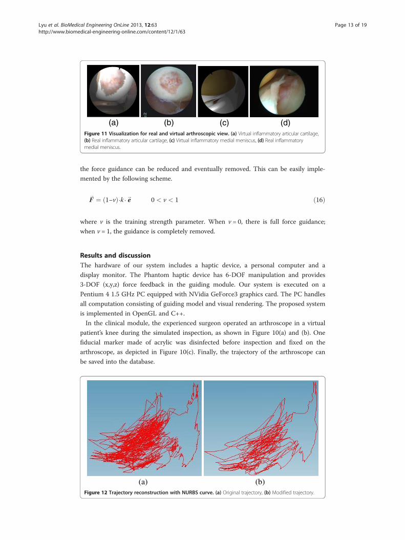
(a) (b)Figure 12 Trajectory reconstruction with NURBS curve. (a) Original trajectory, (b) Modified trajectory.

Figure 13 The user interface: The left window is external viewpoint window and the right windowis arthroscopic viewpoint window (The red points are the insertions for the arthroscope).
Lyu et al. BioMedical Engineering OnLine 2013, 12:63 Page 14 of 19http://www.biomedical-engineering-online.com/content/12/1/63
Virtualization
In the proposed system, a virtual knee-joint model can be obtained from the database.
The original surface of the virtual knee-joint model was black and white. However, it is
now enriched with color detail in the visualization because of the texture mapping, as
indicated in Figure 11.
Filtering of tracking data by NURBS
After the virtual knee-joint model is loaded, the previous trajectory of the arthroscope
for the inspection is also retrieved from the database. The original trajectory has been
filtered by NURBS and produced much smoother trajectory curves. The noises in the
Figure 14 The visualization of the trajectory.

Figure 15 Force Guidance of Inspection Trajectory.
Lyu et al. BioMedical Engineering OnLine 2013, 12:63 Page 15 of 19http://www.biomedical-engineering-online.com/content/12/1/63
original trajectory of the arthroscope were effectively filtered and the amount of data
was much compressed (see Figure 12).
User interface
The clinical scenario is displayed on a LCD panel, which contains two separate windows,
as shown in Figure 13 (Additional file 1). The external viewpoint window displays the
surgical scene as viewed form an external viewpoint such as surgeon’s view. This view can
be adjusted depending on the surgeon’s preference by changing the camera position,
orientation and magnification. The arthroscopic viewpoint window can display the
recorded clinical view, as well as the virtual view. Although the virtual view is created by
simulation, the clinical arthroscopic view is mapped onto the surfaces of the virtual knee-
joint compartments in the virtual view. The trainees can switch between these two views
if the patient’s medical images are previously obtained. Otherwise, the trainees can only
see the virtual view.
Force guidance of inspection trajectory
The trainees can see the trajectory in the proposed system as shown in Figure 14. Then,
users can feel the force guidance by the haptic device when their virtual probe head de-
viates from the planned trajectory, as indicated in Figure 15.
(a) (b)Figure 16 The training trajectory and error. (a) 3-D motion, (b) The path error.

Table 1 Without the force guidance
A B C D E F G H
AVG. 1 (cm) 0.288 0.7 0.204 0.476 0.331 0.541 0.378 1.525
SD. 1 0.13 0.37 0.136 0.21 0.134 0.247 0.183 1.059
Time (Second) 24.914 13.923 28.855 13.895 15.995 14.222 16.623 30.095
AVG. 2 (cm) 0.183 0.45 0.447 0.383 0.212 0.261 0.219 0.545
SD. 2 0.168 0.35 0.24 0.181 0.145 0.183 0.155 0.325
Time (Second) 13.418 13.745 14.059 9.859 15.232 7.323 15.614 12.041
Lyu et al. BioMedical Engineering OnLine 2013, 12:63 Page 16 of 19http://www.biomedical-engineering-online.com/content/12/1/63
Evaluation
In this paper, we evaluate that the force guidance improves the training for inspection of
the knee. Thus, eight participants perform an inspection of the knee whose trajectory is
obtained from an experienced surgeon in the clinical module. All participants were right-
handed and they operated the same inspection with and without force guidance. To evalu-
ate participants’ performance, the normal path error and operating time were recorded.
The normal path error was based on the trajectory from experienced surgeon in clinical
module and the movements of the Phantom tip operated by each participant. A 3D motion
of the ideal and experimental trajectory is illustrated in Figure 16(a) (Additional file 2).
Then, the normal path error is the shortest distance between the trajectory from the trainee
and the trajectory from the experienced surgeon, as shown in Figure 16(b).
To avoid differences in performance related to unease with the instruments, they used
initially the haptic device to perform some basic operations without force guidance in the
VR environment [28]. These basic operations were based on the manufacturer established
settings, and were not modified by authors. After achieving familiarity with the haptic de-
vice and basic operations, the participants completed the first inspection without force
guidance and recorded their first operating time and the normal path error as first data.
Then, they repeated the same inspection five times without recording for practice. After
that, they did the inspection again and recorded their operating time and the normal path
error as the second data. Thus, we can understand the learning curve after continuous
practices five times according to the first and second data.
In order to avoid the effect of accumulated learning experience, at least 3 days were
allowed to pass after the completion of the inspection without the force guidance be-
fore we started the new inspection section with the force guidance. The participants
performed the inspection with force guidance in the same manner as before. Data on
the completion time and error were described in Tables 1 and 2.
The experiment reveals that most participants’ performances are better after they re-
peated continuously the same inspection five times. The standard deviations are also
Table 2 With the force guidance
A B C D E F G H
AVG. 1 (cm) 0.168 0.109 0.575 0.248 0.1 0.374 0.378 0.135
SD. 1 0.094 0.078 0.24 0.091 0.094 0.197 0.293 0.067
Time (Second) 13.99 11.195 15.259 9.055 19.964 9.286 9.205 9.668
AVG. 2 (cm) 0.107 0.482 0.357 0.234 0.173 0.187 0.116 0.126
SD. 2 0.065 0.251 0.16 0.134 0.093 0.085 0.113 0.079
Time (Second) 11.114 13.159 8.1 9.232 13.077 8.455 11.782 8.891

0
0.1
0.2
0.3
0.4
0.5
0.6
A B C D E F G H
cm
Subjects
AVG. (w/o force)
AVG. (w/ force)
Figure 17 The subject’s performance of arthroscopic inspection on the same simulator was donewith and without the force guidance.
Lyu et al. BioMedical Engineering OnLine 2013, 12:63 Page 17 of 19http://www.biomedical-engineering-online.com/content/12/1/63
clear indications to show that they performed better after repeating the same operation.
Furthermore, we should notice that most participants’ performances with the force
guidance are better than those without the force guidance, as shown in Figure 17. The
performance includes the mean normal path error, standard deviation and the operat-
ing time. In the experiment, the average error with the force guidance is 33.01% lower
than that without the force guidance. The operating time with the force guidance is
14.95% less than that without the force guidance. Even though B’s second mean normal
path error is larger than the first one in the haptics-enhanced inspection, his second
standard deviation is similar to the first one. It indicates that there were few tremors
during B’s operation. Data on the normal path error showed a trend toward a benefit
from the force guidance in the inspection.
0
0.05
0.1
0.15
0.2
0.25
0.3
0.35
0.4
0.45
0.5
0 100 200 300 400 500 600 700 800 900
Error(cm)
Time (Second)
k = 1
k = 5
k = 10
k = 15
k = 20
Figure 18 The effect for the magnitude of force.
Lyu et al. BioMedical Engineering OnLine 2013, 12:63 Page 18 of 19http://www.biomedical-engineering-online.com/content/12/1/63
The force guidance is important to shorten the learning time. Hence, the magnitude
of force has played an important role in the force guidance. The magnitude of force in
this system can be adjusted by the simulated spring coefficient. Figure 18 indicates that
the higher the spring coefficient, the better the learning result. However, unstable force
will occur if the spring coefficient is set too high.
ConclusionsIn this paper, we have discussed the motivations for developing a novel virtual arthro-
scopic training system. The system focuses on the experience-based inspection of ana-
tomic knee structures. In this system, the trajectory of the arthroscope from an
experienced surgeon can be recorded by vision tracking and built into a database.
Then, the noise of the trajectory can be filtered by NURBS. Data compression advan-
tage is also achieved. After obtaining the NURBS curve, it can be used to review the en-
tire inspection procedure and guide the trainees in the virtual environment.
Furthermore, the clinical arthroscopic view is mapped to the surface of the virtual
knee-joint compartments. Hence, more realistic environment can be visualized. Then,
the trainee can operate the haptic device along the NURBS trajectory during the force
guidance. The trainees will feel the force guidance when their virtual arthroscope probe
head deviates from the planned trajectory. The experimental results suggest that stron-
ger educational effect can be achieved by force guidance for novice trainees. Currently,
the deformation of the soft tissue has not been implemented in the system. In the fu-
ture, we will develop the soft tissue deformation model to strength the simulation ef-
fect. In addition, a specific haptic device will be built to increase the DOF to simulate
the practical treatment. Finally, a multi-metric scoring system will be integrated into
the proposed system to objectively evaluate the users’ performances.
Additional files
Additional file 1: Virtual inspection [http://youtu.be/lKplX2-lc34].
Additional file 2: Virtual Inspection with force guidance [http://youtu.be/hEW0eaKGZP8].
AbbreviationsVR: Virtual reality; MIS: Minimally invasive surgery; CT: Computed tomography; MRI: Magnetic resonance imaging;CCD: Charge-coupled device; NURBS: Non-uniform rational B-spline; AVG: Average; SD: Standard deviation.
Competing interestsThe authors declare that they have no competing interests.
Authors’ contributionsSRL proposed conception, design and drafted the manuscript. YKL participated in its design and coordination andhelped to draft the manuscript. STH participated in the design of the study and performed the analysis. HTYconceived of the study, and participated in coordination and drafted the manuscript. All authors read and approvedthe final manuscript.
AcknowledgementsThis research is supported by the Tzu-Chi Dalin General Hospital Research Project: 98-1-7.
Author details1Joint Center, Tzu-Chi Dalin General Hospital, Chia-yi, Taiwan, ROC. 2Department of Mechanical Engineering, NationalChung Cheng University, Chia-yi, Taiwan, ROC.
Received: 12 March 2013 Accepted: 26 June 2013Published: 4 July 2013

Lyu et al. BioMedical Engineering OnLine 2013, 12:63 Page 19 of 19http://www.biomedical-engineering-online.com/content/12/1/63
References
1. Grechenig W, Fellinger M, Fankhauser F, Weiglein AH: The Graz learning and training model for arthroscopicsurgery. Surg Radiol Anat 1999, 21:347–350.2. Voto S, Clark RN, Zuelzer WA: Arthroscopic training using pig knee joints. Clin Orthop Relat Res 1988, 226:134–137.3. Megali G, Tonet O, Mazzoni M, Dario P, Vascellari A, Marcacci M: A new tool for surgical training in knee
arthroscopy. In Proceedings of the Medical Image Computing and Computer-Assisted Intervention; 25-28 September2002. Edited by Dohi T, Kikinis R. Tokyo: Springer Berlin Heidelberg; 2002:170–177. Lecture Notes in ComputerScience.
4. Mabrey J, Gillogly SD, Kasser JR, Kasser J, Sweeney HJ, Zarins B, Mevis H, Garrett WE Jr, Poss R, Cannon WD: Virtualreality simulation of arthroscopy of the knee. Arthroscopy 2002, 18:e28.
5. Heng P-A, Cheng C-Y, Wong T-T, Xu Y, Chui Y-P, Chan K-M, Tso S-K, Tso SK: A virtual-reality training system forknee arthroscopic surgery. IEEE Trans Inf Technol Biomed 2004, 8:217–227.
6. Bayonat S, Garcia M, Mendoza C, Ferniindez JM: Shoulder arthroscopy training system with force feedback. InProceedings of the International Conference on Medical Information Visualisation─BioMedical Visualisation; 05-07 July.London; 2006.
7. Moody L, Waterworth A, McCarthy A, Harley P, Smallwood R: The feasibility of a mixed reality surgical trainingenvironment. Virtual Reality 2008, 12:77–86.
8. Tuijthof GJ, van Sterkenburg MN, Sierevelt IN, van Oldenrijk J, Van Dijk CN, Kerkhoffs GM: First validation of thePASSPORT training environment for arthroscopic skills. Knee Surg Sports Traumatol Arthrosc 2010, 18:218–224.
9. Tuijthof GJ, Visser P, Sierevelt IN, Van Dijk CN, Kerkhoffs GM: Does perception of usefulness of arthroscopicsimulators differ with levels of experience? Clin Orthop Relat Res 2011, 469:1701–1708.
10. Wang Y, Xiong Y, Xu K, Liu D: vKASS: asurgical procedure simulation system for arthroscopic anterior cruciateligament reconstruction. Comput Animat Virtual Worlds 2012, 24:25–41.
11. InsightArthroVR®. [http://insightarthrovr.gmv.com/index_en.htm].12. ARTHRO Mentor™. [http://simbionix.com/simulators/arthro-mentor/].13. Feygin D, Keehner M, Tendick R: Haptic guidance: experimental evaluation of a haptic training method for a
perceptual motor skill. In Proceedings of the 10th International Symposium on Haptic Interfaces for VirtualEnvironment and Teleoperator Systems; 24-25 March 2002. Orlando; 2002:40–47.
14. Jérémy Bluteau SC, Payan Y, Gentaz E: Haptic guidance improves the visuo-manual tracking of trajectories.PLoS One 2008, 3:e1775.
15. Kim Y, Yang U, Jo D, Lee G, Choi J, Park J: Efficient multi-pass welding training with haptic guide. In BookEfficient multi-pass welding training with haptic guide. City: ACM; 2009:1-1.
16. Morris D, Tan H, Barbagli F, Chang T, Salisbury K: Haptic Feedback Enhances Force Skill Learning. In Proceedingsof the Second Joint EuroHaptics Conference and Symposium on Haptic Interfaces for Virtual Environment andTeleoperator Systems; 22-24 March 2007. Tsukuba; 2007:21–26.
17. Palluel-Germain R, Bara F, de Boisferon AH, Hennion B, Gouagour P, Gentaz E: A Visuo-Haptic Device -Telemaque - Increases Kindergarten Children's Handwriting Acquisition. In Proceedings of the Second JointEuroHaptics Conference and Symposium on Haptic Interfaces for Virtual Environment and Teleoperator Systems;22-24 March 2007. Tsukuba; 2007:72–77.
18. Xing-Dong Y, Bischof WF, Boulanger P: Validating the Performance of Haptic Motor Skill Training. In Proceedingsof the Symposium on Haptic Interfaces for Virtual Environment and Teleoperator Systems; 13-14 March 2008.Washington, DC; 2008:129–135.
19. Jabero M, Sarment DP: Advanced surgical guidance technology: a review. Implant Dent 2006, 15:135–142.20. Sutherland I: A head-mounted three dimensional display. In Proceedings of Fall Joint Computer Conference, part I:
09-11 December 1968. San Francisco; 1968:757–764.21. Shahidi R, Bax MR, Maurer CR, Johnson JA, Wilkinson EP, Wang B, West JB, Citardi MJ, Manwaring KH, Khadem R:
Implementation, calibration and accuracy testing of an image-enhanced endoscopy system. IEEE Trans MedImag 2002, 21:1524–1535.
22. Maintz JBA, Viergever MA: A survey of medical image registration. Med Image Anal 1998, 2:1–36.23. Tsai R: A versatile camera calibration technique for high accuracy 3D machine vision metrology using off-the-shelf
TV cameras and lenses. IEEE J Robotics Automation 1987, 3:323–344.24. Zhang Z: A flexible new technique for camera calibration. IEEE Trans Pattern Anal Mach Intell 2000, 22:1330–1334.25. Kato H, Billinghurst M: Marker tracking and HMD calibration for a video-based augmented reality
conferencing system. In Proceedings of the 2nd IEEE and ACM International Workshop on Augmented Reality; 20-21October 1999. San Francisco; 1999:85–94.
26. Piegl L, Tiller, Wayne: The NURBS Book. 2nd edition. New York: Springer -Verlag; 1997.27. Wang J-B, Yau H-T: Real-time NURBS interpolator: application to short linear segments. Int J Adv Manuf Technol
2009, 41:1169–1185.28. Panait L, Akkary E, Bell RL, Roberts KE, Dudrick SJ, Duffy AJ: The role of haptic feedback in laparoscopic
simulation training. J Surg Res 2009, 156:312–316.
doi:10.1186/1475-925X-12-63Cite this article as: Lyu et al.: Experience-based virtual training system for knee arthroscopic inspection.BioMedical Engineering OnLine 2013 12:63.