Embed Size (px)
Citation preview

E XPANDING MANDR E LS AND S LE E VE S
Double Angle Advantages
The continuing advancement in production methods in the Metalworking Industry has dcreated a need for precision workholding devices capable of automatic clamping in component bores. In addition, the equipment must transmit the high accuracy of the latest machine tools and develop sufficient holding power to resist the cutting forces imposed on the workpiece.
Such capabilities are possible by using a BIRLA KENNAMETAL Expanding mandrel system. The BIRLA KENNAMETAL Expanding Mandrels, a development of the Erickson Tool Company, Ohio, USA patented double angle princle for precision expansion, have been proved over a number of years as the most versatile and troublefree Mandrels for jobs requiring internal chucking where accuracy positive grip are necessary
The continuing advancement in production methods in the Metalworking Industry has created a need for precision workholding devices capable of automatic clamping in component bores. In addition, the equipment must transmit the high accuracy of the latest machine tools and develop sufficient holding power to resist the cutting forces imposed on the workpiece.
Such capabilities are possible by using a BIRLA PRECISION TECH Expanding mandrel system. The BIRLA PRECISION TECH Expanding Mandrels, a development of the Erickson Tool Company, Ohio, USA patented double angle princle for precision expansion, have been proved over a number of years as the most versatile and troublefree Mandrels for jobs requiring internal chucking where accuracy positive grip are necessary
EXPANDING MANDRELS AND SLEEVES
DOUBLE ANGLE ADVANTAGES
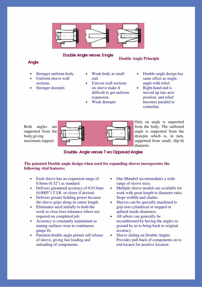
Double Angle verses S ingle
Angle Double Angle Principle
• Stronger uniform body. • Uniform sleeve wall
sections. • Stronger drawpin
• Weak body at small end.
• Uneven wall sections on sleeve make it difficult to get uniform expansion.
• Weak drawpin
• Double-angle design has same effect as single-angle with relief.
• Right-hand end is moved up into new position, and relief becomes parallel to centreline.
Both angles are supported from the body;giving maximum support
Only on angle is supported from the body. The outboard angle is supported from the drawpin which is, in turn, supported from small, slip-fit diameter.
Double- Angle verses T wo Opposed Angles
The patented Double angle design when used for expanding sleeves incorporates the following vital features:
• Each sleeve has an expansion range of 0.8mm (0.32") as standard.
• Delivers guranteed accuracy of 0.013mm (0.0005") T.I.R. or closer if desired.
• Delivers greater holding power because the sleeve grips along its entire length.
• Eliminates need initially to hold the work to close bore tolerance where not required on completed job.
• Accuracy is constantly maintained as mating surfaces wear to continuous gauge fit.
• Patented double angle permit self release of sleeve, giving fast loading and unloading of components.
• One Mandrel accommodates a wide range of sleeve sizes.
• Multiple sleeve models are available for work with great length to diameter ratio. Stops wobble and chatter.
• Sleeves can be specially machined to grip non-cylindrical or stepped or splined inside diameters.
• All arbors can generally be reconditioned by having the angles re-ground by us to bring back to original accuracy.
• Sleeve sliding on Double Angles Provides pull-back of components on to end locator for positive location.

Mounting and pre-loading instructions
Assembly Instructions
• Ensure machine drawbar is fully forward. • Load mandrel body to machine spindle (using clock register or double angle form check
concentricity). • Fit end locator to mandrel body (if not already fitted). • Ensure double angles are clean. (Mandrel body and sleeve.) • Place expanding sleeve on mandrel body. • Ensure pre-load adjustment screw is retracted. Place expander pin in mandrel body. Screw
pin clockwise into drawbar until head of pin contracts with sleeve. (Ensure pin does not expand sleeve.)
• Load component on to mandrel assembly in working position. • Screw expander pin clockwise into drawbar until sleeve grips component. • Back off expander pin anti-clockwise until first available pre-load flat is adjacent to pre-
load adjustment screw.(Cross lines on expander pin head cioncide with pre-load flats.) • Remove component and check loading clearance to ensure easy loading. • Tighten pre-load adjustment screw ensuring expander pin ahs slight radial movement, to
allow pin to slide freely. • Finally check by loading component and operate drawbar ensuring component is
satisfactorily held. Make sure drawbar pressure is sufficient to stop slippage. • Mandrel is now ready for operation.
Birla Kennametal engineers are always available to assist if required.
Birla Precision Tech engineers are always available to assist if required
MOUNTING AND PRELOADING INSTRUCTIONS
ASSEMBLY INSTRUCTIONS

Face plate drawbar operated (standard length)
The faceplate drawbar operated expanding mandrel can be used on any machine with drawbar facility, for general turning and grinding operations. Adaptor plates can be made to suit the
machine mounting if necessary. Component end locators, solid type or compensating ( for out-of-square locating faces) can be supplied or manufactured by customer. The natural pull-back action of the sleeve ensures the component is hard against the location face. There is an over-expansion
stop built into the expander pin to avoid over-stressing the expanding sleeve.
A N R Model
Min Max B C D E F G H J K L M
DP ø DP ø Too Nr
3A 12,5 16,0 60 20,0 22,0 14,6 20 40 75 11,0 6 12,6 M4 58 M8 28,0 M4 90.800.210.1 2C 16,0 22,0 66 20,0 27,0 15,0 22 40 75 15,0 6 14,1 M8 58 M8 28,0 M4 90.800.215.1 1C 22,0 28,0 72 20,0 32,0 15,5 30 40 75 20,0 6 20,7 M8 58 M8 58 M6 90.800.221.1
18C 28,0 41,0 79 20,0 38,0 15,3 31 40 75 26,5 6 26,3 M10 58 M8 58 M6 90.800.227.1 4C 41,0 63,5 84 20,0 43,0 14,8 36 40 75 37,5 6 36,0 M12 58 M8 58 M6 90.800.234.1 5C 63,5 76,2 109 25,0 51,0 25,3 36 60 120 55,0 6 57,3 M20 94 M10 94 M8 90.800.241.1 6C 76,2 89,0 118 25,0 57,0 24,7 37 60 120 74,5 6 71,1 M20 94 M10 94 M8 90.800.248.1 7C 89,0 130,0 133 30,0 63,5 25,2 47 100 180 86,5 6 84,1 M24 150 M12 150 M10 90.800.253.1 8C 130,0 178,0 153 30,0 79,5 24,6 22 100 180 124,5 6 123,0 M36 150 M12 150 M10 90.800.259.1
For maximum effciency expansion sleeves must be preload to maintain contact with mandrel double angles at all times.
Face plate drawbar operated (standard length)

S pigot drawbar operated (standard Length)
The spigot drawbar operated expanding mandrel can be used on any machine with drawbar facilities for general turning and grinding operations. Adaptors plates made to suit machine mounting, can be manufactured by BIRLA KENNAMETAL or customer. Component end locators, solid type or compensating ( for out-of-square locating faces) can be supplied or manufactured by customer. The natural pull-back action of the sleeve ensures the component is hard against the location face. There is an over-expansion stop built into the expander pin to avoid over-stressing the expanding sleeve.
A Model Min Max
B C D E F G H J K L M Tool Nr
3A 12,5 16,0 66 11,0 22 9,8 20 20 26 11,0 14 9,5 M4 90.810.210.1 2C 16,0 22,0 70 11,0 27 8,0 20 20 26 15,0 18 14,1 M8 90.810.215.1 1C 22,0 28,5 85 11,0 32 10,0 27 30 40 20,0 17 20,7 M8 90.820.221.1
18C 28,5 41,0 92 11,0 38 10,5 27 30 40 26,3 18 26,3 M10 90.820.227.1 4C 41,0 63,5 99 13,0 43 9,5 27 30 50 37,0 21 37,0 M12 90.820.234.1
For maximum effciency expansion sleeves must be preload to maintain contact with mandrel double angles at all times.
The spigot drawbar operated expanding mandrel can be used on any machine with drawbar facilities for general turning and grinding operations. Adaptors plates made to suit machine mounting, can be manufactured by BIRLA PRECISION TECH or customer. Component end locators, solid type or compensating ( for out-of-square locating faces) can be supplied or manufactured by customer. The natural pull-back action of the sleeve ensures the component is hard against the location face. There is an over-expansion stop built into the expander pin to avoid over-stressing the expanding sleeve.
Spigot drawbar operated (standard length)

Between centres (standard length)
The thread operated between centres expanding madrel is generally used mounted betwen 60 degree centres, and can be driven from drive flats witha carrier or drive plates. It is possible to attach a simple component end locator, if required, at diameter L. These Mandrels are generally used for small batch grinding operations. There is a ground diameter to adapt this mandrel to face plate mounted, if required, by use of an adaptor plate. These Mandrels are hand operated by use of conventional spanners. These mandrels are often used for inspection purposes.
A Model
Min Max B C D E F G H J
A / F K L M Tool Nr
3A 12,5 16,0 77 11,0 22,0 21,0 20 20 26,0 10 18 9,5 22 90.811.110.1 2C 16,0 22,0 83 11,0 27,0 20,0 20 20 26,0 13 18 14,1 22 90.811.115.1 1C 22,0 28,0 99 11,0 32,0 21,5 27 30 40,0 19 27 20,7 36 90.821.121.1
18C 28,5 41,0 107 11,0 38,0 21,2 27 30 40,0 24 27 26,3 36 90.821.127.1 4C 41,0 63,5 120 13,0 43,0 23,0 27 30 50,0 36 27 37,0 46 90.821.134.1 5C 63,5 76,2 145 -- 51,0 26,0 35 40 57,3 55 35 57,3 50 90.831.141.1 6C 76,2 89,0 155 -- 57,0 26,3 35 50 71,1 65 45 71,1 60 90.841.148.1 7C 89,0 130,0 205 -- 63,5 44,0 50 60 84,1 85ø 55 84,1 70 90.851.153.1 8C 130,0 178,0 235 -- 79,5 55,5 50 80 123,0 124ø 73 123,1 105 90.861.159.1
For maximum effciency expansion sleeves must be preload to maintain contact with mandrel double angles at all times.
Between centres (standard length)

Modular Expanding Mandrels Nut operated face-plate (standard length)
The faceplate thread operated expanding mandral can be used on any machine with no drawbar facility, for general turning and grinding operations. Adaptor plates can be made to suit the machine mounting if necessary. Component end locators, solid type or compensating (for out-of-square locating faces) can be supplied or manufactured by customer. The natural pull-back action of the sleeve ensures the component is hard against the location face.
A N R Model
Min Max B C D E F G J
A/F K L DP ø DP ø
Too Nr
3A 12,5 16,0 73 20,0 22,0 15,0 40 75 10 6 12,6 58 M8 28 M4 90.800.110.1 2C 16,0 22,0 79 20,0 27,0 15,0 40 75 13 6 14,1 58 M8 28 M4 90.800.115.1 1C 22,0 28,5 86 20,0 32,0 15,5 40 75 19 6 20,7 58 M8 58 M6 90.800.121.1
18C 28,5 41,0 94 20,0 38,0 15,2 40 75 24 6 26,3 58 M8 58 M6 90.800.127.1 4C 41,0 63,5 105 20,0 43,0 15,0 40 75 36 6 37,0 58 M8 58 M6 90.800.134.1 5C 63,5 76,2 134 25,0 51,0 25,0 60 120 55 6 57,3 94 M10 94 M8 90.800.141.1 6C 76,2 89,0 144 25,0 57,0 25,0 60 120 65 6 71,1 94 M10 94 M8 90.800.148.1 7C 89,0 130,0 166 30,0 63,5 25,0 100 180 85ø 6 84,1 150 M12 150 M10 90.800.153.1 8C 130,0 178,0 185 30,0 79,5 25,0 100 180 124ø 6 123,0 150 M12 150 M10 90.800.159.1
For maximum effiiciency expansion sleeves must be preloaded to maintain contact with mandral double angles at all times
Modular Expanding MandrelsNut operated face-plate (standard length

Cantilever operated ( standard length)
The Cantilever model expanding mandrel is used on machines with morse taper machine mounting. These mandrels can be used for general turning or grinding operations. Particularly useful for blind bores. These Mandrels are hand operated by use of a 'C' spanner , and are suitable for small batch work. There is an over-expansion stop built into the expandar pin to avoid over-stressing the expanding sleeve.
A Model Min Max
B B1 C D E F G H J K L * Tool Nr # Tool Nr
3A 12,5 16,0 141,0 127,0 3,2 22,0 4,0 66,0 48 9,5 11 2 M10 90.592.510.1 90.582.510.1 2C 16,0 22,0 155,0 141,0 4,0 27,0 10,0 80,0 50 14,1 15 2 M10 90.592.515.1 90.582.515.1 1C 22,0 28,5 189,0 171,0 5,0 32,0 14,0 95,0 60 20,6 20 3 M10 90.593.521.1 90.583.521.1
18C 28,5 41,0 202,5 184,5 5,5 38,0 15,0 108,0 70 26,3 27 3 M12 90.593.527.1 90.583.527.1 4C 41,0 63,5 246,5 224,5 6,0 43,0 25,5 129,0 90 37,0 37 4 M16 90.594.534.1 90.584.534.1 5C 63,5 76,2 260,0 238,0 8,0 51,0 24,5 142,5 100 57,3 55 4 M16 90.594.541.1 90.584.541.1 6C 76,2 89,0 320,0 292,0 11,0 57,0 23,5 170,5 110 71,1 75 5 M20 90.595.548.1 90.585.548.1 7C 89,0 130,0 323,0 295,0 14,0 63,5 27,0 173,5 130 84,1 86 5 M20 90.595.553.1 90.585.553.1
For maximum efficiency expansion sleeves must be prepoaded to maintain contact with mandral double angles at all times. * Can be supplied with or without tang # If without tang will be drawbar held
Cantilever operated (standard length)

Standard length sleeve specification
A Model Min Max
Length Tool Nr
3A1 12,5 16,0 22,0 92.000.20.x.x.xxx 2C1 16,0 22,0 27,0 92.050.20.x.x.xxx 1C1 22,0 28,5 32,0 92.100.20.x.x.xxx
18C1 28,5 41,0 38,0 92.150.20.x.x.xxx 4C1 41,0 63,5 43,0 92.200.20.x.x.xxx 5C1 63,5 76,0 51,0 92.250.20.x.x.xxx 6C1 76,0 89,0 57,0 92.300.20.x.x.xxx
*7C1 89,0 130,0 63,5 92.350.20.x.x.xxx *8C1 130,0 178,0 80,0 92.400.20.x.x.xxx
A Model Min Max
Length Tool Nr
3A2 16,5 22,0 26,0 92.001.20.x.x.xxx 2C2 22,0 28,5 32,0 92.051.20.x.x.xxx 1C2 28,5 40,0 38,0 92.101.20.x.x.xxx
18C2 40,0 51,0 45,0 92.151.20.x.x.xxx 4C2 51,0 73,0 50,0 92.201.20.x.x.xxx 5C5 73,0 89,0 60,0 92.251.20.x.x.xxx 6C2 89,0 102,0 69,5 92.301.20.x.x.xxx *7C2 101,0 143,0 78,5 92.351.20.x.x.xxx
*8C2 143,0 178,0 99,5 92.401.20.x.x.xxx * These itmes will be stocked as turned blanks only, and will therfore require an extended delivery. x . x . xxx = Sleeve Dia in mm, i.e. 123.26mm=1.2.326, i.e. 30mm = 0.3.000 These sleeves can be used with all types of mandrel, and are interchangeble within the range of each type. Example: The 3A drawbar operated mandrel will accept a 3A1 or 3A2 sleeve which may have been originally used on a 3A thread operated mandrel.
Standard length sleeve specification

Order Information
To enable BIRLA PRECISION TECH to provide a prompt service, we would recommend customer's orders should specify the type and model number of the Mandrel. Additionally, when ordring sleeves, the type and model number, with the component diameter to be held. All sleeve orders must specify type, model number. The component bore and tolerance to be gripped. All sleeves will be held in stock in a semi-finished condition ready for qualification to customers required gripping diameter.
Example : 1off face plate expanding mandrel, Type 18C. Tool No. 90.800.227.11off standard sleeve, Type 18C1 to grip 38.1mm dia. bore Tool No 92.150.200.3.810
Instructions for Grinding Sleeves to Size
When Sleeves are purchased, unqualified by BIRLA PRECISION TECH, they must be ground to size, preferably on a Birla Precision Tech between centres mandrel. If a between centres mandrel is not available, the sleeves may be ground on the mandrel on which they are to be used.
Between centres type : Mount between centres on grinding machines.
Face plate drawbar operated type : Make slave nut for drawbar to expand sleeve. Mount onface plate or in a jaw chuck
Cantilever type : Mount in grinding machine with morse taper bore.
1. Ensure mandrel and sleeve double angles are clean and free of any burrs.2. Check size of sleeve in relaxed condition.3. Expand sleeve as per schedule.4. Rough grind outside diameter to size required plus 0,07/0,10mm (.003/.004"). Note thatgrinding should be done carefully to avoid distortion at this stage.5. Remove sleeve and clean throughly. Outside diameter should be 0,025/0,050mm(.001/.002") below required size.6. Reload sleeve on mandrel and expand to (Stage4) size it was rough ground.7. Check concentricity (to make sure no distortion has taken place.)8. Finish grind outside diameter to required size.9. Check final size and concentricity.

R ecommended expended positions
Sleeve Range Expanded Position 3A 0,13mm (.005") 2A 0,13mm (.005") 1C 0,13mm (.005") 18C 0,13mm (.005") 4C 0,26mm (.010") 5C 0,26mm (.010") 6C 0,26mm (.010") 7C 0,39mm (.015") 8C 0,39mm (.015")
Recommended expanded positions

End locators and adaptors plates
The examples shown below cover the three basic designs of end locators and adaptors plates. These are generally designed to customer requirements. Therefore they can be suplied by BIRLA KENNAMETAL manufactured by the customer. These designs can be adapted for use on various types of mandrels.
End locators and adaptors platesThe examples shown below cover the three basic designs of end locators and adaptors plates. These are generally designed to customer requirements. Therefore they can be suplied by BIRLA PRECISION TECH manufactured by the customer. These designs can be adapted for use on various types of mandrels.

Special Sleeves
BIRLA KENNAMETAL have available a comprehensive range of special sleeves that have been developed to accommodate the varying conditions and the more difficult work holding problems modern industry is faced with. This range includes:-
• Flush types in all lengths. • Half length types. • Double length types. • Segmented types for large expansion and excessive driving requirements. • Serrated types for spline location and holding on internal gear forms (either minor or
pitch line diameter location)and types for holding on irregular forms. • Types to give expansion up to 6.3mm (1/4") on diameter for large diameter components.
Certain applications demand that the unit to be supplied must be capable of transmitting high torque to resist heavy cutting forces. In these instances we supply segmented type sleeves which take the form of solid segments held together with spring steel retainer rings. Each segment is located on the mandrel body by location keys to determine the radial position of each segment.This style of sleeve provides an item which has increased hardness to prevent wear and less ability to fracture in the event of a machine malfunction. All sleeves, other than segmented types, can be supplied with the slots bonded with Ericplast as specials. This is recommended to swarf away from double angle from to prolong life and accuracy.
Special Sleeves
BIRLA PRECISION TECH are available in a comprehensive range of special sleeves that have been developed to accommodate the varying conditions and the more difficult work holding problems modern industry is faced with. This range includes:-
Flush types in all lengths.• Half length types.• Double length types.• Segmented types for large expansion and excessive driving requirements.• Serrated types for spline location and holding on internal gear forms (either minor or• pitch line diameter location)and types for holding on irregular forms.• Types to give expansion up to 6.3mm (1/4") on diameter for large diameter components.•
Certain applications demand that the unit to be supplied must be capable of transmitting high torque to resist heavy cutting forces. In these instances we supply segmented type sleeves which take the form of solid segments held together with spring steel retainer rings. Each segment is located on the mandrel body by location keys to determine the radial position of each segment.This style of sleeve provides an item which has increased hardness to prevent wear and less ability to fracture in the event of a machine malfunction.
All sleeves, other than segmented types, can be supplied with the slots bonded with Ericplast as specials. This is recommended to swarf away from double angle from to prolong life and accuracy.

Special Applications
Engineering Service : Whilst most holding operations can be successfully obtained by using the modular system and good tool design following the basic instructions, BIRLA KENNAMETAL offer to you the engineering ' know-how' that has solved thousands of workholding problems worldwide by our collaborator Kennametal Erickson. Special mandral Applications : BIRLA KENNAMETAL have, at your disposal, an experienced engineering team, who, over the years, have solved many thousands of workholding problems. The very problem you face may have been solved by us for some other manufacturer. With some basic details supplied as below, BIRLA KENNAMETAL would be able to establish your requirement and promptly offer a recommendation and quotation. The Details are:-
1. Full component details. 2. Previous machine operations. 3. Machining operation required. 4. Stock removal. 5. Feeds and speeds. 6. Type of machine. 7. Machine mounting details. 8. Quantity required.
Special Applications
Engineering Service : Whilst most holding operations can be successfully obtained by using themodular system and good tool design following the basic instructions, BIRLA PRECISION TECH offer to you the engineering 'know-how' that has solved thousands of workholding porblems world-wide by our collaborator Kennametal Erickson.
Special mandrel Applications : BIRLA PRECISION TECH have, at your disposal, an experienced engineering team, who, over the years, have solved many thousands of workholding problems.
The very problem you face may have been solved by us for some other manufacturer. With somebasic details supplied as below, BIRLA PRECISION TECH would be able to establish your require-ment and promptly offer a recommendation and quotation.
The Details are:-1. Full component details.2. Previous machine operations.3. Machining operation required.4. Stock removal.5. Feeds and speeds.6. Type of machine.7. Machine mounting details.8. Quantity required.


![Conventional Gas Lift Mandrels · PDF fileConventional gas lift mandrels are installed as part of ... The Camco* conventional injection-pressure-operated gas ... [25.4] BK series JK](https://img.dokumen.tips/doc/110x75/5aa0502e7f8b9a76178dd7f1/conventional-gas-lift-mandrels-gas-lift-mandrels-are-installed-as-part-of-the.jpg)