Embed Size (px)
Citation preview
RFID LabGildas Avoine, 2014Contact: [email protected]
Objective: Learn how much it is easy to read contactless tags, possibly simulate/clone.
Requirement:• Hardware: Reader SCL3711 or ACR122, Reader Proxmark3, Mifare Ultralight Tik-itag, Blank Mifare Ultralight, Mifare UltralightC.
• Software: LibNFC, TamaShell, eLockpicking.
• Computer skills: Basics on Linux, Hexadecimal notation.
Exercise 1: Set up the Environment
This RFID Lab uses the LibNFC library, which directly access to USB devices, contrarilyto the PCSC library for example. As a consequence, each command during this RFIDLab should be run in super user mode (sudo <command>) to avoid any access right issues.
LibNFC manages devices compliant with the Near Field Communication (NFC) technol-ogy, which is part of the 13.56MHz Radio Frequency IDentification (RFID) technology.
1. Check the Reader is Properly Connected to USB Port
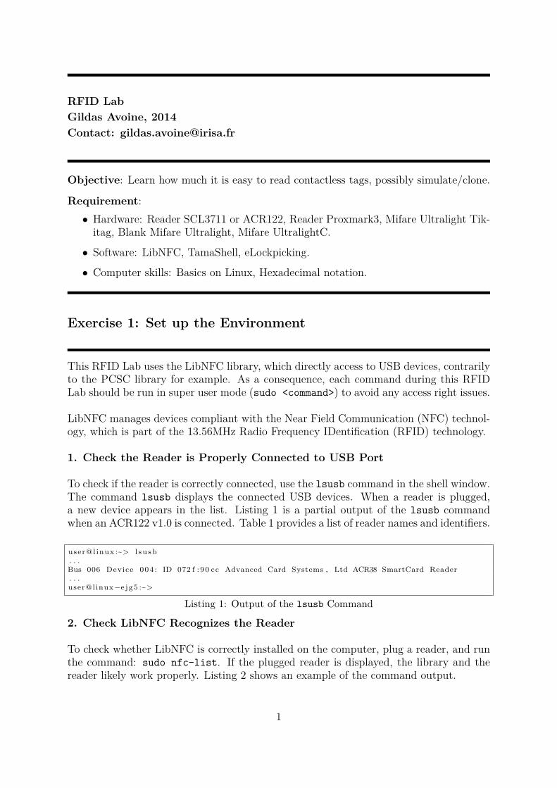
To check if the reader is correctly connected, use the lsusb command in the shell window.The command lsusb displays the connected USB devices. When a reader is plugged,a new device appears in the list. Listing 1 is a partial output of the lsusb commandwhen an ACR122 v1.0 is connected. Table 1 provides a list of reader names and identifiers.
user@l inux :~> l s u s b. . .Bus 006 Device 004 : ID 072 f : 90 cc Advanced Card Systems , Ltd ACR38 SmartCard Reader. . .user@linux−e jg5 :~>
Listing 1: Output of the lsusb Command
2. Check LibNFC Recognizes the Reader
To check whether LibNFC is correctly installed on the computer, plug a reader, and runthe command: sudo nfc-list. If the plugged reader is displayed, the library and thereader likely work properly. Listing 2 shows an example of the command output.
1
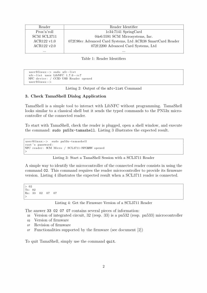
Reader Reader IdentifierProx’n’roll 1c34:7141 SpringCard
SCM SCL3711 04e6:5591 SCM Microsystems, Inc.ACR122 v1.0 072f:90cc Advanced Card Systems, Ltd ACR38 SmartCard ReaderACR122 v2.0 072f:2200 Advanced Card Systems, Ltd
... ...
Table 1: Reader Identifiers
user@l inux :~> sudo nfc− l i s tnfc− l i s t uses LibNFC 1.7.0 − rc7NFC dev i ce : / CCID USB Reader openeduser@l inux :~>
Listing 2: Output of the nfc-list Command
3. Check TamaShell Dialog Application
TamaShell is a simple tool to interact with LibNFC without programming. TamaShelllooks similar to a classical shell but it sends the typed commands to the PN53x micro-controller of the connected reader.
To start with TamaShell, check the reader is plugged, open a shell window, and executethe command: sudo pn53x-tamashell. Listing 3 illustrates the expected result.
user@l inux :~> sudo pn53x−tamashe l lroot ’ s password :NFC reader : SCM Micro / SCL3711−NFC&RW opened>
Listing 3: Start a TamaShell Session with a SCL3711 Reader
A simple way to identify the microcontroller of the connected reader consists in using thecommand 02. This command requires the reader microcontroller to provide its firmwareversion. Listing 4 illustrates the expected result when a SCL3711 reader is connected.
> 02Tx : 02Rx : 33 02 07 07>
Listing 4: Get the Firmware Version of a SCL3711 Reader
The answer 33 02 07 07 contains several pieces of information:33 Version of integrated circuit, 32 (resp. 33) is a pn532 (resp. pn533) microcontroller02 Version of firmware07 Revision of firmware07 Functionalities supported by the firmware (see document [2])
To quit TamaShell, simply use the command quit.
2
Exercise 2: Poll a Tag
The polling is the method to detect if a tag is on the reader.
To communicate with ISO7816-compliant tags, computer applications use APDUs (Ap-plication Protocol Data Unit) that are sent to the reader, then to the tag. Readers mayrequire the application to embed the APDU into a pseudo-APDU containing additionalinformation used by the reader only. Pseudo-APDUs may also be used to execute internalcommands in the reader (in such a case the APDU is not sent to the tag).
An APDU consists of two parts, namely the request and the answer. An APDU requestis always sent by the computer application while a response is always sent by the readeror the tag. A response is received only if a request was previously sent.
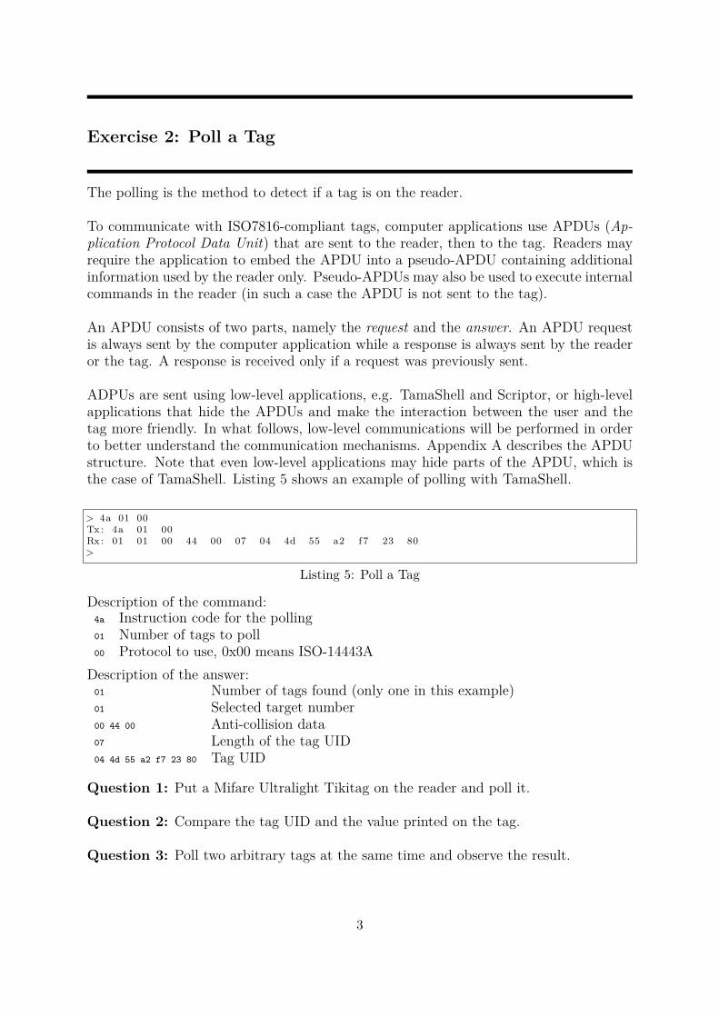
ADPUs are sent using low-level applications, e.g. TamaShell and Scriptor, or high-levelapplications that hide the APDUs and make the interaction between the user and thetag more friendly. In what follows, low-level communications will be performed in orderto better understand the communication mechanisms. Appendix A describes the APDUstructure. Note that even low-level applications may hide parts of the APDU, which isthe case of TamaShell. Listing 5 shows an example of polling with TamaShell.
> 4a 01 00Tx : 4a 01 00Rx : 01 01 00 44 00 07 04 4d 55 a2 f7 23 80>
Listing 5: Poll a Tag
Description of the command:4a Instruction code for the polling01 Number of tags to poll00 Protocol to use, 0x00 means ISO-14443A
Description of the answer:01 Number of tags found (only one in this example)01 Selected target number00 44 00 Anti-collision data07 Length of the tag UID04 4d 55 a2 f7 23 80 Tag UID
Question 1: Put a Mifare Ultralight Tikitag on the reader and poll it.
Question 2: Compare the tag UID and the value printed on the tag.
Question 3: Poll two arbitrary tags at the same time and observe the result.
3
Exercise 3: Read Data from a Mifare Ultralight Tag
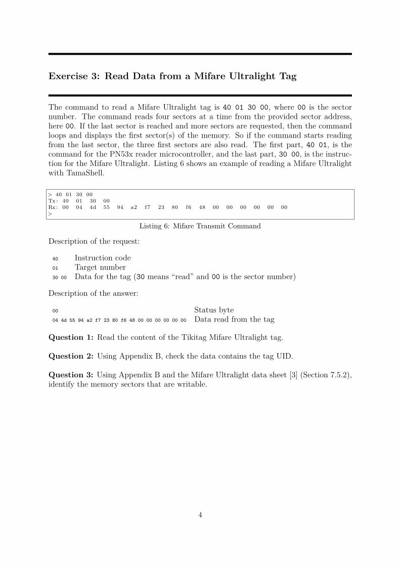
The command to read a Mifare Ultralight tag is 40 01 30 00, where 00 is the sectornumber. The command reads four sectors at a time from the provided sector address,here 00. If the last sector is reached and more sectors are requested, then the commandloops and displays the first sector(s) of the memory. So if the command starts readingfrom the last sector, the three first sectors are also read. The first part, 40 01, is thecommand for the PN53x reader microcontroller, and the last part, 30 00, is the instruc-tion for the Mifare Ultralight. Listing 6 shows an example of reading a Mifare Ultralightwith TamaShell.
> 40 01 30 00Tx : 40 01 30 00Rx : 00 04 4d 55 94 a2 f7 23 80 f6 48 00 00 00 00 00 00>
Listing 6: Mifare Transmit Command
Description of the request:
40 Instruction code01 Target number30 00 Data for the tag (30 means “read” and 00 is the sector number)
Description of the answer:
00 Status byte04 4d 55 94 a2 f7 23 80 f6 48 00 00 00 00 00 00 Data read from the tag
Question 1: Read the content of the Tikitag Mifare Ultralight tag.
Question 2: Using Appendix B, check the data contains the tag UID.
Question 3: Using Appendix B and the Mifare Ultralight data sheet [3] (Section 7.5.2),identify the memory sectors that are writable.
4
Exercise 4: Write Data on a Mifare Ultralight Tag
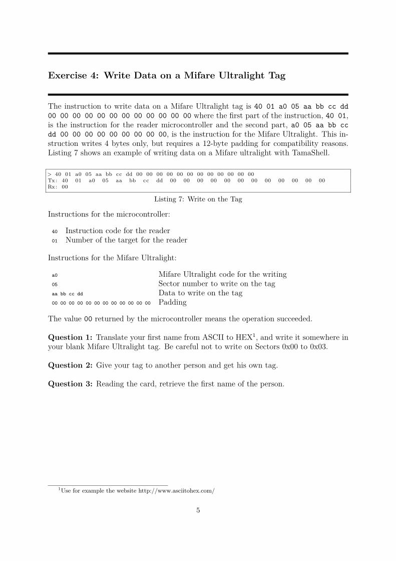
The instruction to write data on a Mifare Ultralight tag is 40 01 a0 05 aa bb cc dd00 00 00 00 00 00 00 00 00 00 00 00 where the first part of the instruction, 40 01,is the instruction for the reader microcontroller and the second part, a0 05 aa bb ccdd 00 00 00 00 00 00 00 00 00, is the instruction for the Mifare Ultralight. This in-struction writes 4 bytes only, but requires a 12-byte padding for compatibility reasons.Listing 7 shows an example of writing data on a Mifare ultralight with TamaShell.
> 40 01 a0 05 aa bb cc dd 00 00 00 00 00 00 00 00 00 00 00 00Tx : 40 01 a0 05 aa bb cc dd 00 00 00 00 00 00 00 00 00 00 00 00Rx : 00
Listing 7: Write on the Tag
Instructions for the microcontroller:
40 Instruction code for the reader01 Number of the target for the reader
Instructions for the Mifare Ultralight:
a0 Mifare Ultralight code for the writing05 Sector number to write on the tagaa bb cc dd Data to write on the tag00 00 00 00 00 00 00 00 00 00 00 00 Padding
The value 00 returned by the microcontroller means the operation succeeded.
Question 1: Translate your first name from ASCII to HEX1, and write it somewhere inyour blank Mifare Ultralight tag. Be careful not to write on Sectors 0x00 to 0x03.
Question 2: Give your tag to another person and get his own tag.
Question 3: Reading the card, retrieve the first name of the person.
1Use for example the website http://www.asciitohex.com/
5
Exercise 5: Authentication with Mifare UltralightC
Exercice 5 aims to explain how the authentication protocol of a Mifare UltralightC tagcan be performed using APDUs.
Theory
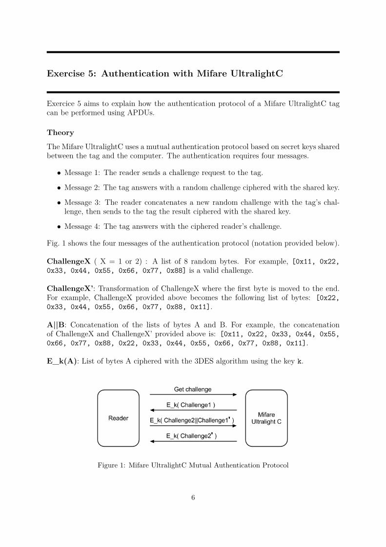
The Mifare UltralightC uses a mutual authentication protocol based on secret keys sharedbetween the tag and the computer. The authentication requires four messages.
• Message 1: The reader sends a challenge request to the tag.
• Message 2: The tag answers with a random challenge ciphered with the shared key.
• Message 3: The reader concatenates a new random challenge with the tag’s chal-lenge, then sends to the tag the result ciphered with the shared key.
• Message 4: The tag answers with the ciphered reader’s challenge.
Fig. 1 shows the four messages of the authentication protocol (notation provided below).
ChallengeX ( X = 1 or 2) : A list of 8 random bytes. For example, [0x11, 0x22,0x33, 0x44, 0x55, 0x66, 0x77, 0x88] is a valid challenge.
ChallengeX’: Transformation of ChallengeX where the first byte is moved to the end.For example, ChallengeX provided above becomes the following list of bytes: [0x22,0x33, 0x44, 0x55, 0x66, 0x77, 0x88, 0x11].
A||B: Concatenation of the lists of bytes A and B. For example, the concatenationof ChallengeX and ChallengeX’ provided above is: [0x11, 0x22, 0x33, 0x44, 0x55,0x66, 0x77, 0x88, 0x22, 0x33, 0x44, 0x55, 0x66, 0x77, 0x88, 0x11].
E_k(A): List of bytes A ciphered with the 3DES algorithm using the key k.
Figure 1: Mifare UltralightC Mutual Authentication Protocol
6
Example
Step 1
The first step consists in getting a challenge from the tag. The TamaShell command is 421a 00. Listing 8 shows an example of the “get challenge” process. Document [4] providesmore details about the Mifare UltralightC.
> 42 1a 00Tx : 42 1a 00Rx : 00 a f cc 7e 3c 23 74 14 32 c7>
Listing 8: Request for a challenge
The last 8 bytes of the answer are the ciphered challenge:
E_k(Challenge1) is [0xcc, 0x7e, 0x3c, 0x23, 0x74, 0x14, 0x32, 0xc7]
Step 2
The tag challenge should now be deciphered with the 3DES algorithm, the key 49 45 4D4B 41 45 52 42 21 4E 41 43 55 4F 59 46, an initialization vector equal to zero, and nopadding. Listing 9 shows an example of deciphering. The detail of this command is outof the scope of this lab.
user@l inux :~> echo cc7e3c23741432c7 | xxd −p −r | o p e n s s l enc −des−ede−cbc −d−K 49454 D4B41455242214E4143554F5946 −i v 0000000000000000 −nopad | xxd −p
0 db776b547d3b2ecuser@l inux :~>
Listing 9: Decipher the Tag Challenge
The following list of bytes is Challenge1:[0x0d, 0xb7, 0x76, 0xb5, 0x47, 0xd3, 0xb2, 0xec]
Step 3
The tag challenge, Challenge1, must be converted to Challenge1’. The following list ofbytes [0x0d, 0xb7, 0x76, 0xb5, 0x47, 0xd3, 0xb2, 0xec] becomes [0xb7, 0x76,0xb5, 0x47, 0xd3, 0xb2, 0xec, 0x0d]. Remember, the first byte goes at the end ofthe list.
Step 4
The reader side must generate its challenge too, Challenge2. For example the followinglist of bytes: [0x11, 0x22, 0x33, 0x44, 0x55, 0x66, 0x77, 0x88].
Step 5
This step consists in concatenating Challenge2 with Challenge1’, which leads withthe data from step 3 and 4 to: [0x11, 0x22, 0x33, 0x44, 0x55, 0x66, 0x77, 0x88,0xb7, 0x76, 0xb5, 0x47, 0xd3, 0xb2, 0xec, 0x0d]
7
Step 6
The concatenated list of bytes must be ciphered before to be sent to the tag. Listing 12shows an example of the ciphering process. The data of the step 5 is used. This is thesecond ciphered message exchanged. From now until the end of the communication, eachinitialization vector will be the least significant 8 bytes of the last messageexchanged with the tag. So in this case, the initialization vector is the ciphered chal-lenge received from the tag at Step 1, namely E_k(Challenge1).
user@l inux :~> echo 1122334455667788 b776b547d3b2ec0d | xxd −p −r | o p e n s s l enc −des−ede−cbc−e −K 49454 D4B41455242214E4143554F5946 −i v cc7e3c23741432c7 −nopad | xxd −p
0 c9e12133590921ba9c0d46f774f f159user@l inux :~>
Listing 10: Cipher Computer and Tag Challenges
The result is E_k(Challenge2||Challenge1’) = [0x0c, 0x9e, 0x12, 0x13, 0x35,0x90, 0x92, 0x1b, 0xa9, 0xc0, 0xd4, 0x6f, 0x77, 0x4f, 0xf1, 0x59]
Step 7
The second part of the authentication protocol is done by sending to the tag the command42 af followed by the 16 bytes of Step 6. Listing 11 illustrates this communication. Ifthe tag’s answer is RF Transmission Error, this means the authentication has failed.Otherwise, the result of the command is E_k(Challenge2’), which should be in thisexample [0x06, 0xc2, 0x1e, 0xd4, 0x3e, 0x60, 0xd6, 0x3d].
> 42 a f 0c 9e 12 13 35 90 92 1b a9 c0 d4 6 f 77 4 f f 1 59Tx : 42 a f 0c 9e 12 13 35 90 92 1b a9 c0 d4 6 f 77 4 f f 1 59Rx : 00 00 06 c2 1e d4 3e 60 d6 3d>
Listing 11: Send the Ciphered Message
Step 8
The last step is the deciphering of the tag’s answer. The initialization vector is the last 8bytes exchanged with the tag, i.e., the last 8 bytes of E_k(Challenge2||Challenge1’).
user@l inux :~> echo 06 c21ed43e60d63d | xxd −p −r | o p e n s s l enc −des−ede−cbc −d−K 49454 D4B41455242214E4143554F5946 −i v a9c0d46 f774 f f 159 −nopad | xxd −p
2233445566778811user@l inux :~>
Listing 12: Decipher the Tag’s Answer
If the result of this command is the following list of bytes, Challenge2’: [0x22, 0x33,0x44, 0x55, 0x66, 0x77, 0x88, 0x11], then authentication succeeded.
Practice Yourself
Question 1: Make an authentication with a Mifare UltralightC using the default key.
Question 2: Read Sector 0x05 to Sector 08.
Question 3: Is the key used in this exercise the default key provided in Appendix C?.
8
Exercise 6: Eavesdropping and Simulating with a Proxmark
Exercice 6 aims to demontrates how easy is the simulation of a HF tag.
Proxmark Set Up
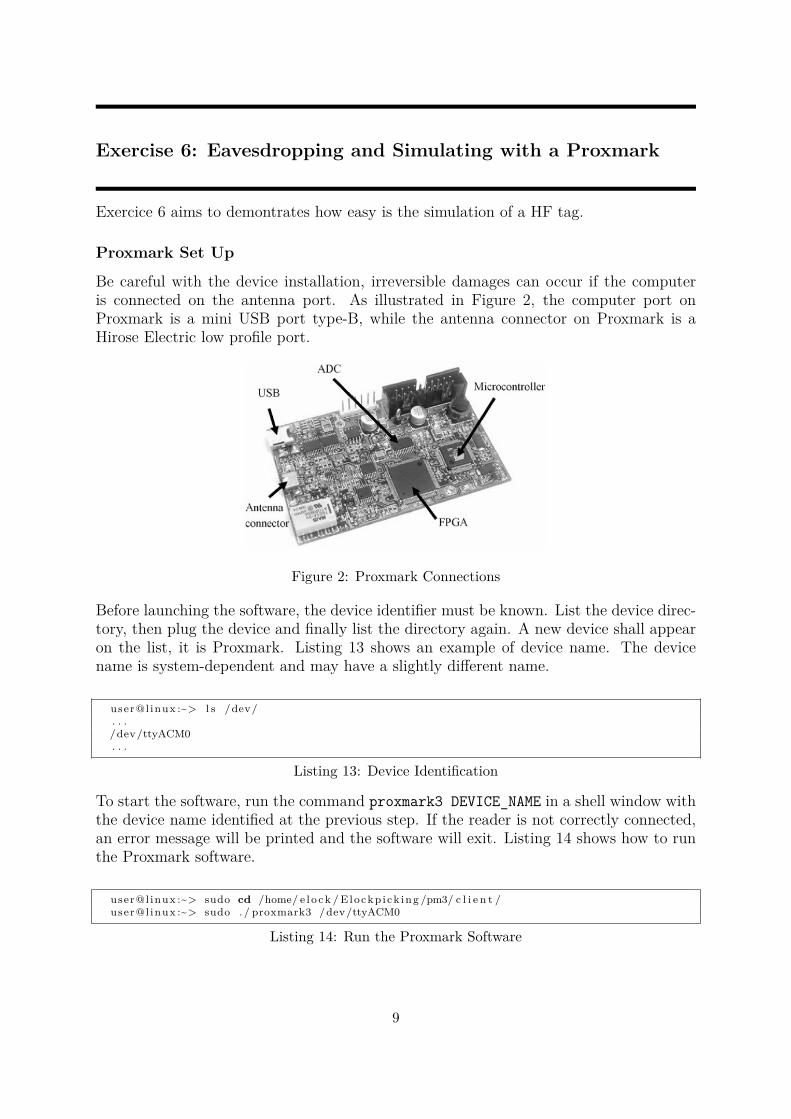
Be careful with the device installation, irreversible damages can occur if the computeris connected on the antenna port. As illustrated in Figure 2, the computer port onProxmark is a mini USB port type-B, while the antenna connector on Proxmark is aHirose Electric low profile port.
Figure 2: Proxmark Connections
Before launching the software, the device identifier must be known. List the device direc-tory, then plug the device and finally list the directory again. A new device shall appearon the list, it is Proxmark. Listing 13 shows an example of device name. The devicename is system-dependent and may have a slightly different name.
user@l inux :~> l s /dev/. . ./dev/ttyACM0. . .
Listing 13: Device Identification
To start the software, run the command proxmark3 DEVICE_NAME in a shell window withthe device name identified at the previous step. If the reader is not correctly connected,an error message will be printed and the software will exit. Listing 14 shows how to runthe Proxmark software.
user@l inux :~> sudo cd /home/ e l o c k / Elockp ick ing /pm3/ c l i e n t /user@l inux :~> sudo . / proxmark3 /dev/ttyACM0
Listing 14: Run the Proxmark Software
9
The last step is the antenna connection, plug the high frequency antenna on the connec-tion port of the reader. Then run the command hw tune in the Proxmark software. Ifthe antenna is correctly connected, the voltage printed on the output next to HF antennawill have a positive value. Listing 15 shows an output example. There is no LF antennaconnected, so the LF antenna voltage has a zero value. If the HF antenna has a zerovalue, check the connection and the antenna. Proxmark is now ready to be used.
proxmark3> hw tune#db# Measuring antenna c h a r a c t e r i s t i c s , p l e a s e wait . . .#db# Measuring complete , sending repor t back to hos t
# LF antenna : 0.00 V @ 125.00 kHz# LF antenna : 0.00 V @ 134.00 kHz# LF opt imal : 0.00 V @ 12000.00 kHz# HF antenna : 8.80 V @ 13.56 MHz# Your LF antenna i s unusab le .proxmark3>
Listing 15: Test the Antenna
Eavesdroping a Communication
Eavesdropping is one of the most interesting feature of Proxmark. The following exercisewill show how to eavesdrop a communication and how to analyze the captured data.
To eavesdrop, put the Proxmark antenna between a Mifare Ultralight tag and a reader.Start the eavesdropping with the command hf 14a snoop in Proxmark’s shell. Poll andread the tag using for example Tamashell (polling is 4a 01 00 and reading the first sectoris 40 01 30 00). Press Proxmark’s button to stop eavesdropping. Finally, use hf 14alist in Proxmark’s shell to obtain the eveadropped messages.
Question 1: Eavesdrop and analyze the anticollision process. Use the datasheet ofMifare Ultralight [3] to identify the following requests sent from the reader: REQA, an-ticollision pass 1, select level 1, anticollision pass 2. And the following answers sent fromthe tag: ATQA, SAK, UID part 1, and UID part 2.
Emulating a Communication
In this part, no tag is needed. Proxmark will be the tag. Remove the Mifare Ultralighttag from the reader but let the Proxmark antenna on the SCL3711 or ACR122 reader.The emulation is done using the Proxmark command hf 14a sim.
Question 2: Emulate a Mifare Ultralight tag with the 7-byte UID: 11223344556677.
Question 3: Poll the tag with the SCL3711 or ACR122 reader. Conclude.
10
Appendix A: Application Protocol Data Unit
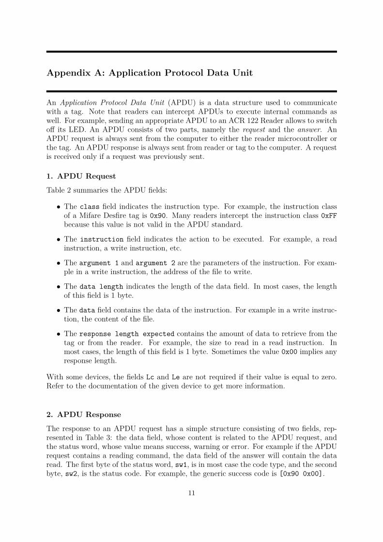
An Application Protocol Data Unit (APDU) is a data structure used to communicatewith a tag. Note that readers can intercept APDUs to execute internal commands aswell. For example, sending an appropriate APDU to an ACR 122 Reader allows to switchoff its LED. An APDU consists of two parts, namely the request and the answer. AnAPDU request is always sent from the computer to either the reader microcontroller orthe tag. An APDU response is always sent from reader or tag to the computer. A requestis received only if a request was previously sent.
1. APDU Request
Table 2 summaries the APDU fields:
• The class field indicates the instruction type. For example, the instruction classof a Mifare Desfire tag is 0x90. Many readers intercept the instruction class 0xFFbecause this value is not valid in the APDU standard.
• The instruction field indicates the action to be executed. For example, a readinstruction, a write instruction, etc.
• The argument 1 and argument 2 are the parameters of the instruction. For exam-ple in a write instruction, the address of the file to write.
• The data length indicates the length of the data field. In most cases, the lengthof this field is 1 byte.
• The data field contains the data of the instruction. For example in a write instruc-tion, the content of the file.
• The response length expected contains the amount of data to retrieve from thetag or from the reader. For example, the size to read in a read instruction. Inmost cases, the length of this field is 1 byte. Sometimes the value 0x00 implies anyresponse length.
With some devices, the fields Lc and Le are not required if their value is equal to zero.Refer to the documentation of the given device to get more information.
2. APDU Response
The response to an APDU request has a simple structure consisting of two fields, rep-resented in Table 3: the data field, whose content is related to the APDU request, andthe status word, whose value means success, warning or error. For example if the APDUrequest contains a reading command, the data field of the answer will contain the dataread. The first byte of the status word, sw1, is in most case the code type, and the secondbyte, sw2, is the status code. For example, the generic success code is [0x90 0x00].
11
Field name Short name Field lengthClass of the instruction CLA 1 byteInstruction INS 1 byteArgument 1 P1 1 byteArgument 2 P2 1 byteData length Lc 1 to 3 bytesData - Lc byteResponse length expected Le 1 to 3 byte
Table 2: APDU Fields
Field name Short name Field lengthResponse data data Le bytesStatus word sw1-sw2 2 bytes
Table 3: APDU Answer
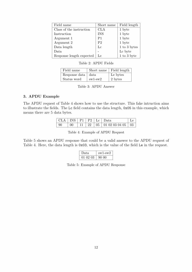
3. APDU Example
The APDU request of Table 4 shows how to use the structure. This fake intruction aimsto illustrate the fields. The Lc field contains the data length, 0x05 in this example, whichmeans there are 5 data bytes.
CLA INS P1 P2 Lc Data Le90 00 11 22 05 01 02 03 04 05 03
Table 4: Example of APDU Request
Table 5 shows an APDU response that could be a valid answer to the APDU request ofTable 4. Here, the data length is 0x03, which is the value of the field Le in the request.
Data sw1-sw201 02 03 90 00
Table 5: Example of APDU Response
12
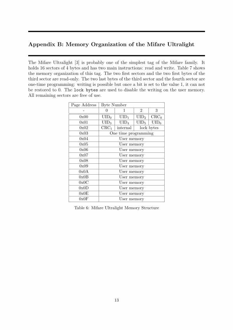
Appendix B: Memory Organization of the Mifare Ultralight
The Mifare Ultralight [3] is probably one of the simplest tag of the Mifare family. Itholds 16 sectors of 4 bytes and has two main instructions: read and write. Table 7 showsthe memory organization of this tag. The two first sectors and the two first bytes of thethird sector are read-only. The two last bytes of the third sector and the fourth sector areone-time programming: writing is possible but once a bit is set to the value 1, it can notbe restored to 0. The lock bytes are used to disable the writing on the user memory.All remaining sectors are free of use.
Page Address Byte Number- 0 1 2 3
0x00 UID0 UID1 UID2 CRC00x01 UID3 UID4 UID5 UID60x02 CRC1 internal lock bytes0x03 One time programming0x04 User memory0x05 User memory0x06 User memory0x07 User memory0x08 User memory0x09 User memory0x0A User memory0x0B User memory0x0C User memory0x0D User memory0x0E User memory0x0F User memory
Table 6: Mifare Ultralight Memory Structure
13
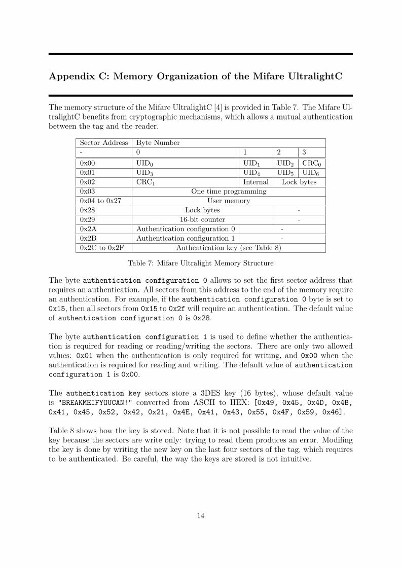
Appendix C: Memory Organization of the Mifare UltralightC
The memory structure of the Mifare UltralightC [4] is provided in Table 7. The Mifare Ul-tralightC benefits from cryptographic mechanisms, which allows a mutual authenticationbetween the tag and the reader.
Sector Address Byte Number- 0 1 2 30x00 UID0 UID1 UID2 CRC00x01 UID3 UID4 UID5 UID60x02 CRC1 Internal Lock bytes0x03 One time programming0x04 to 0x27 User memory0x28 Lock bytes -0x29 16-bit counter -0x2A Authentication configuration 0 -0x2B Authentication configuration 1 -0x2C to 0x2F Authentication key (see Table 8)
Table 7: Mifare Ultralight Memory Structure
The byte authentication configuration 0 allows to set the first sector address thatrequires an authentication. All sectors from this address to the end of the memory requirean authentication. For example, if the authentication configuration 0 byte is set to0x15, then all sectors from 0x15 to 0x2f will require an authentication. The default valueof authentication configuration 0 is 0x28.
The byte authentication configuration 1 is used to define whether the authentica-tion is required for reading or reading/writing the sectors. There are only two allowedvalues: 0x01 when the authentication is only required for writing, and 0x00 when theauthentication is required for reading and writing. The default value of authenticationconfiguration 1 is 0x00.
The authentication key sectors store a 3DES key (16 bytes), whose default valueis "BREAKMEIFYOUCAN!" converted from ASCII to HEX: [0x49, 0x45, 0x4D, 0x4B,0x41, 0x45, 0x52, 0x42, 0x21, 0x4E, 0x41, 0x43, 0x55, 0x4F, 0x59, 0x46].
Table 8 shows how the key is stored. Note that it is not possible to read the value of thekey because the sectors are write only: trying to read them produces an error. Modifingthe key is done by writing the new key on the last four sectors of the tag, which requiresto be authenticated. Be careful, the way the keys are stored is not intuitive.
14
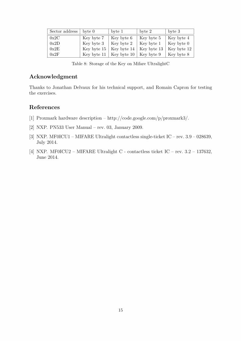
Sector address byte 0 byte 1 byte 2 byte 30x2C Key byte 7 Key byte 6 Key byte 5 Key byte 40x2D Key byte 3 Key byte 2 Key byte 1 Key byte 00x2E Key byte 15 Key byte 14 Key byte 13 Key byte 120x2F Key byte 11 Key byte 10 Key byte 9 Key byte 8
Table 8: Storage of the Key on Mifare UltralightC
Acknowledgment
Thanks to Jonathan Delvaux for his technical support, and Romain Capron for testingthe exercises.
References
[1] Proxmark hardware description – http://code.google.com/p/proxmark3/.
[2] NXP. PN533 User Manual – rev. 03, January 2009.
[3] NXP. MF0ICU1 – MIFARE Ultralight contactless single-ticket IC – rev. 3.9 – 028639,July 2014.
[4] NXP. MF0ICU2 – MIFARE Ultralight C - contactless ticket IC – rev. 3.2 – 137632,June 2014.
15