Embed Size (px)
Citation preview
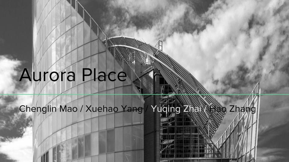
Aurora Place
Chenglin Mao / Xuehao Yang / Yuqing Zhai / Hao Zhang

Contents
Introduction
Structure Features
Foundation System
Load Analysis
Summary
Bibliography

Introduction
1. Background
2. General Information
3. Architects and Engineers
4. Design concept
5. Building layout
6. Interior View
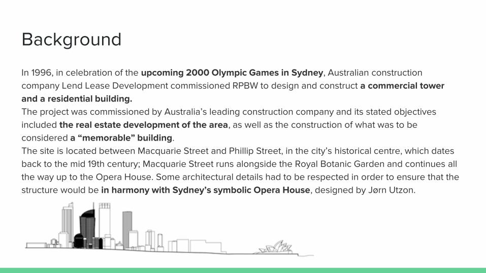
Background
In 1996, in celebration of the upcoming 2000 Olympic Games in Sydney, Australian construction
company Lend Lease Development commissioned RPBW to design and construct a commercial tower
and a residential building.
The project was commissioned by Australia’s leading construction company and its stated objectives
included the real estate development of the area, as well as the construction of what was to be
considered a “memorable” building.
The site is located between Macquarie Street and Phillip Street, in the city’s historical centre, which dates
back to the mid 19th century; Macquarie Street runs alongside the Royal Botanic Garden and continues all
the way up to the Opera House. Some architectural details had to be respected in order to ensure that the
structure would be in harmony with Sydney’s symbolic Opera House, designed by Jørn Utzon.
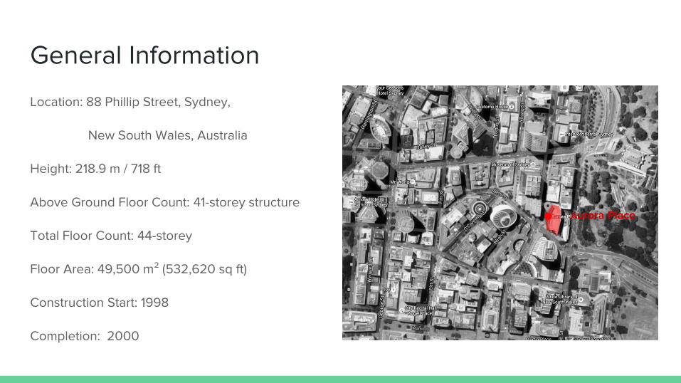
General Information
Location: 88 Phillip Street, Sydney,
New South Wales, Australia
Height: 218.9 m / 718 ft
Above Ground Floor Count: 41-storey structure
Total Floor Count: 44-storey
Floor Area: 49,500 m² (532,620 sq ft)
Construction Start: 1998
Completion: 2000
Aurora Place

General Information
Aurora Place Office and Residential Building Location in City.
Residential Building
Our Focus: Office and Commercial Building
Canopy between two building

Architects: Renzo Piano Building Workshop(RPBW)
Renzo Piano
Born: 14 september 1937( age 78 )
Nationality: Italian
Awards: Pritzker Architecture Prize
RIBA Gold Medal
Sonning Prize
AIA Gold Medal
Kyoto Prize
Engineers: Major Engineers: Bovis Lend lease (structural); Ove
Arup and Partners/Environ (mechanical)
Service and Facade Engineers: Arup
Arup
a British multinational professional services firm
headquartered in London, UK which provides
engineering, design, planning, project management
and consulting services for all aspects of the built
environment.
Architect and Engineers
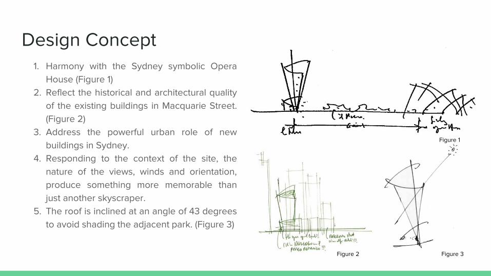
Design Concept 1. Harmony with the Sydney symbolic Opera
House (Figure 1)
2. Reflect the historical and architectural quality
of the existing buildings in Macquarie Street.
(Figure 2)
3. Address the powerful urban role of new
buildings in Sydney.
4. Responding to the context of the site, the
nature of the views, winds and orientation,
produce something more memorable than
just another skyscraper.
5. The roof is inclined at an angle of 43 degrees
to avoid shading the adjacent park. (Figure 3)
Figure 1
Figure 3 Figure 2
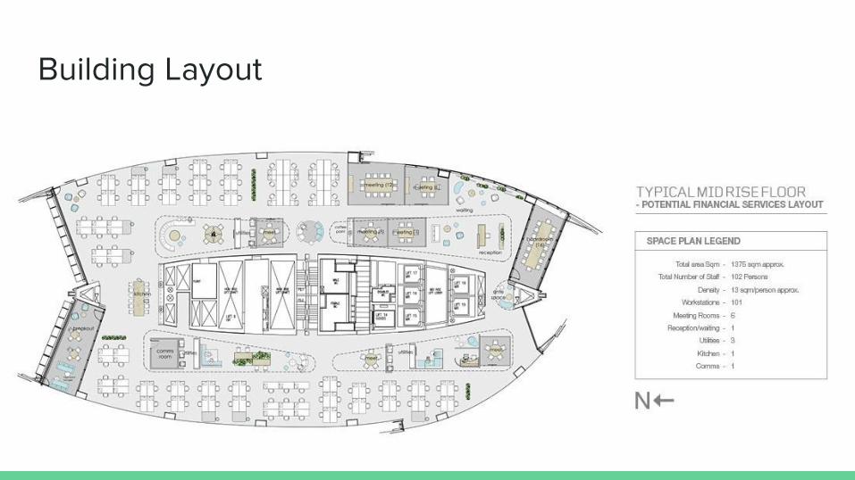
Building Layout
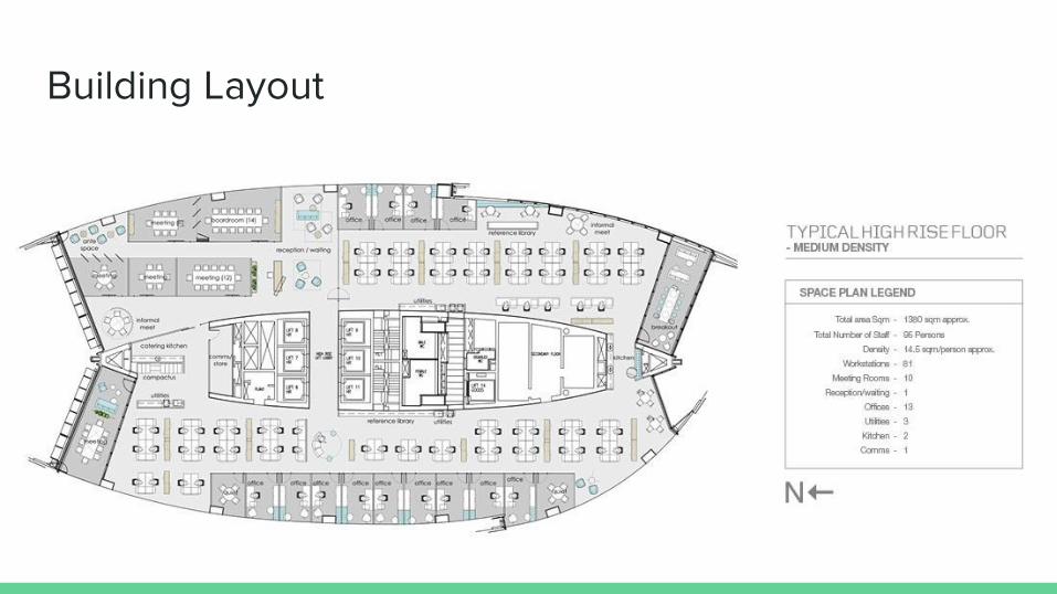
Building Layout

Interior View

Structure Features
1. Structure Component
1. Main Structure System
2. Facade System
2. Connection Description
3. Materials
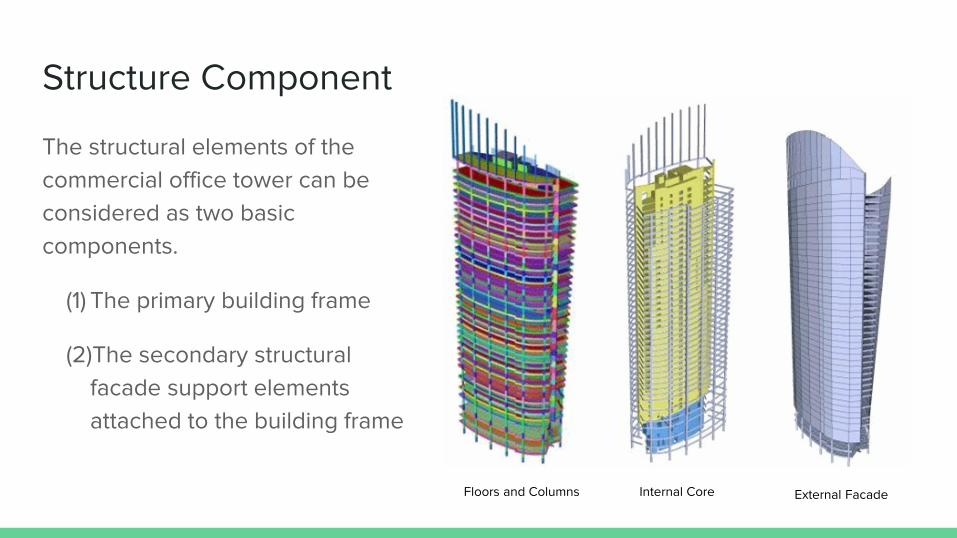
Structure Component
The structural elements of the
commercial office tower can be
considered as two basic
components.
(1) The primary building frame
(2)The secondary structural
facade support elements
attached to the building frame
Floors and Columns Internal Core External Facade
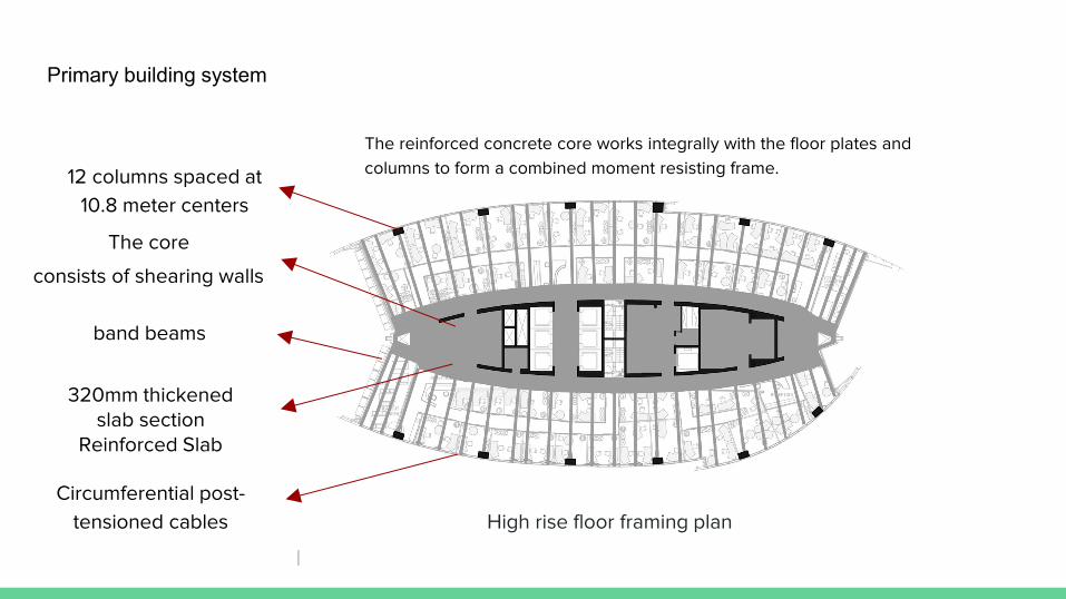
12 columns spaced at
10.8 meter centers
320mm thickened slab section
Reinforced Slab
High rise floor framing plan
The core
consists of shearing walls
Primary building system
provides connection of
the band beams to the
core. It transfers the plate
bending moments and in-
plane diaphragm actions
generated in the floors to
the core walls.
band beams
Circumferential post-
tensioned cables
assists in applying extraneous in-
plane forces from the floors to the
core
These cables also restrain the
forces generated by the
cantilevered and corbelled core
walls located on the northern and
southern ends of the building.
The reinforced concrete core works integrally with the floor plates and
columns to form a combined moment resisting frame.
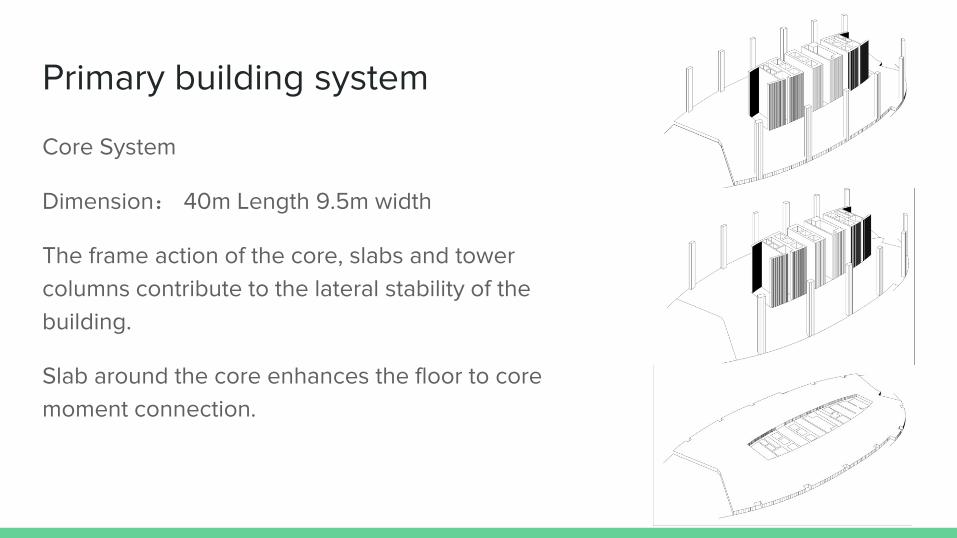
Primary building system
Core System
Dimension: 40m Length 9.5m width
The frame action of the core, slabs and tower
columns contribute to the lateral stability of the
building.
Slab around the core enhances the floor to core
moment connection.
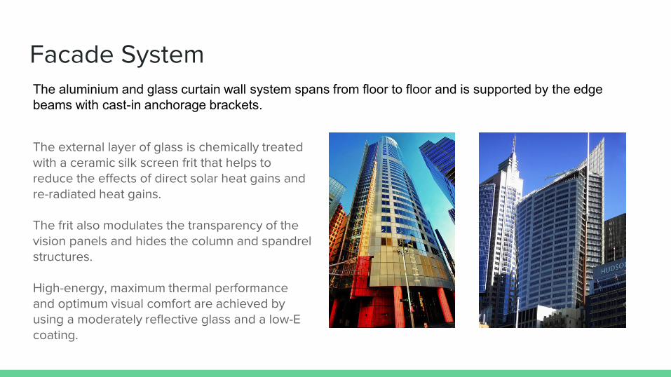
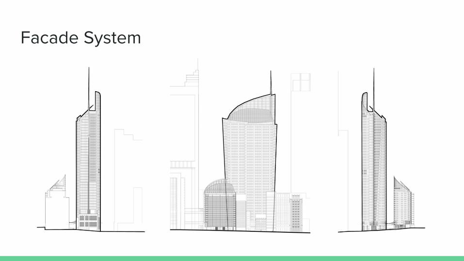
Facade System
The external layer of glass is chemically treated with a ceramic silk screen frit that helps to reduce the effects of direct solar heat gains and re-radiated heat gains. The frit also modulates the transparency of the vision panels and hides the column and spandrel structures. High-energy, maximum thermal performance and optimum visual comfort are achieved by using a moderately reflective glass and a low-E coating.
The aluminium and glass curtain wall system spans from floor to floor and is supported by the edge
beams with cast-in anchorage brackets.
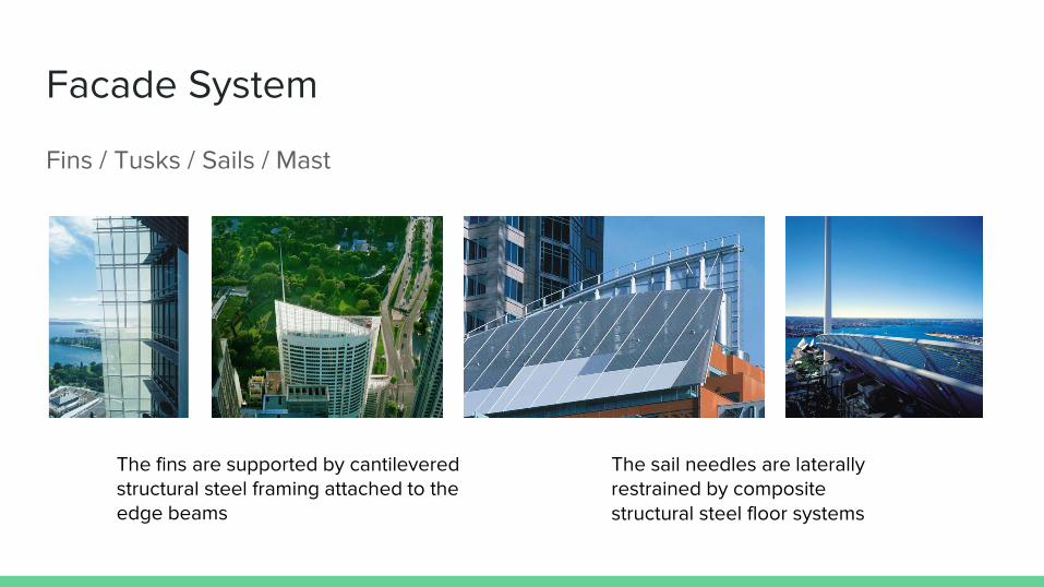
Facade System
Fins / Tusks / Sails / Mast
The sail needles are laterally restrained by composite structural steel floor systems
The fins are supported by cantilevered structural steel framing attached to the edge beams
Facade System
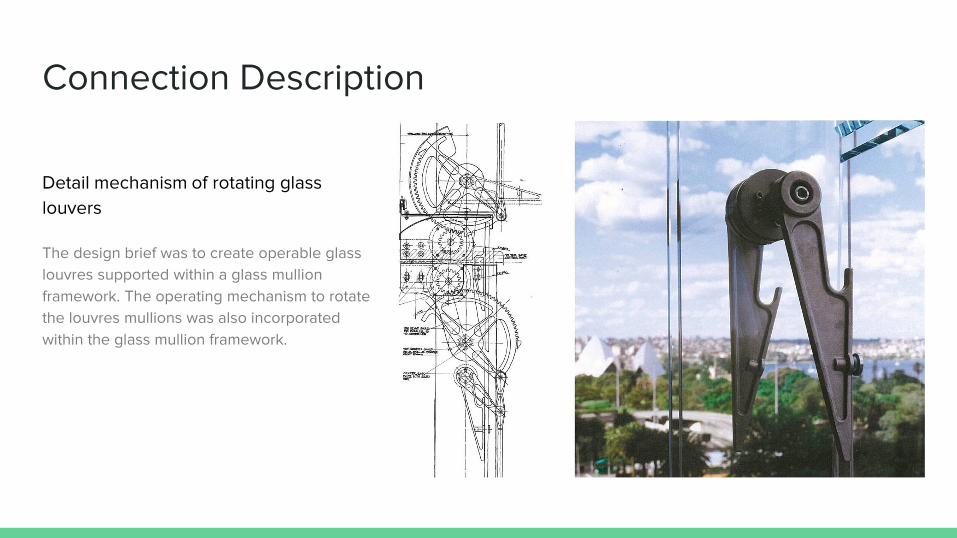
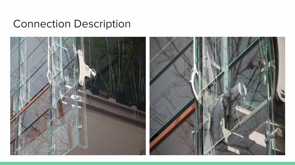
Connection Description
Detail mechanism of rotating glass
louvers
The design brief was to create operable glass
louvres supported within a glass mullion
framework. The operating mechanism to rotate
the louvres mullions was also incorporated
within the glass mullion framework.
Connection Description
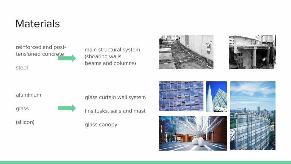
Materials
reinforced and post-tensioned concrete steel aluminium glass (silicon)
main structural system (shearing walls beams and columns) glass curtain wall system fins,tusks, sails and mast glass canopy
Foundation System
1 The geological feature of the site
2 Foundation Design Analysis
3 The advantage of piled raft foundation
4 Other discussions on aseismatic measures in the foundation
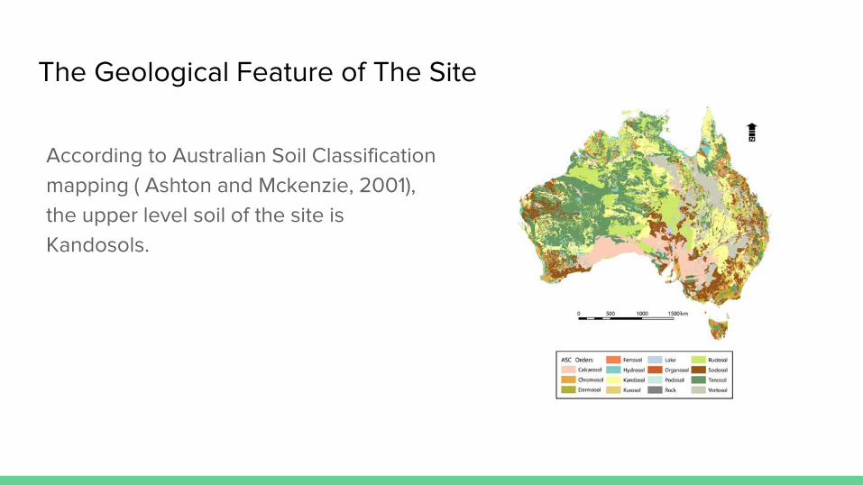
The Geological Feature of The Site
According to Australian Soil Classification
mapping ( Ashton and Mckenzie, 2001),
the upper level soil of the site is
Kandosols.
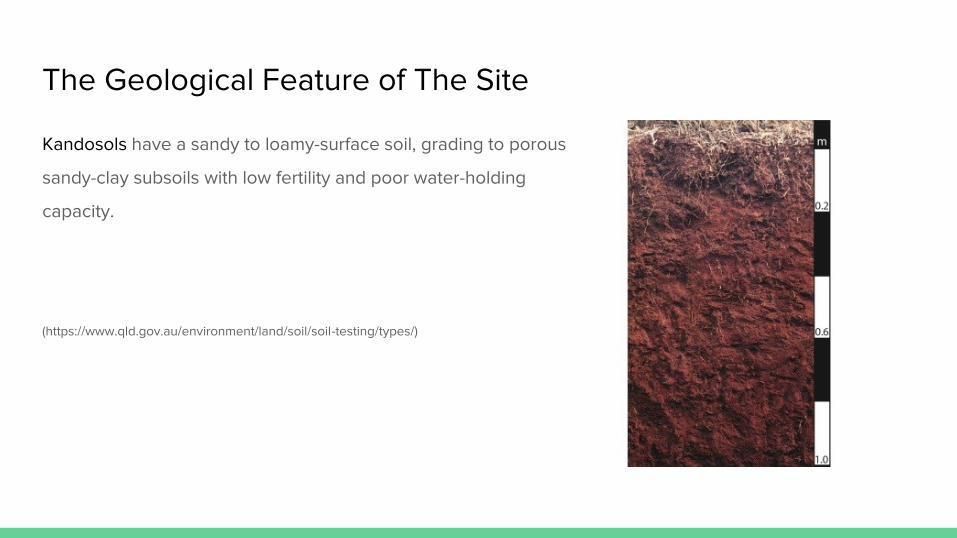
The Geological Feature of The Site
Kandosols have a sandy to loamy-surface soil, grading to porous
sandy-clay subsoils with low fertility and poor water-holding
capacity.
(https://www.qld.gov.au/environment/land/soil/soil-testing/types/)

The Geological Feature of The Site
Bedrock has been found underneath the site. Six
kilometres of sandstone and shale lie under Sydney.
Class2 and Class3 Sydney sandstone( Sydney Basin
Hawkesbury Sandstone) are the bedrocks that the build
found upon.
The Geological Feature of The Site
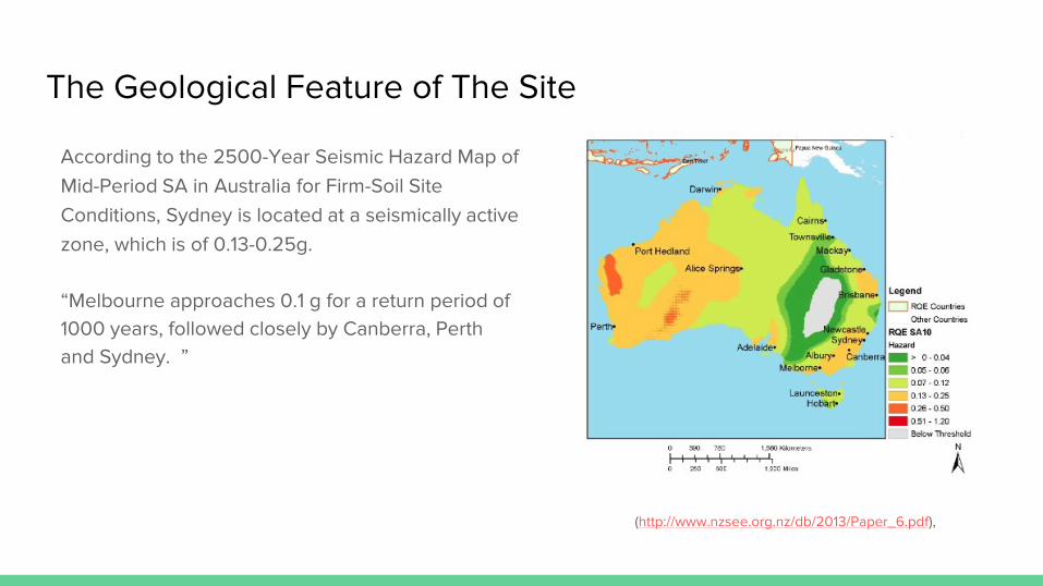
According to the 2500-Year Seismic Hazard Map of
Mid-Period SA in Australia for Firm-Soil Site
Conditions, Sydney is located at a seismically active
zone, which is of 0.13-0.25g.
“Melbourne approaches 0.1 g for a return period of
1000 years, followed closely by Canberra, Perth
and Sydney. ”
(http://www.nzsee.org.nz/db/2013/Paper_6.pdf),

Foundation Design Analysis
1) The relationship between structure and foundation
2) The relationship between foundation and the geological features of the site
3) The Relationship Between Foundation and the Previous Building
The Relationship Between Structure and Foundation
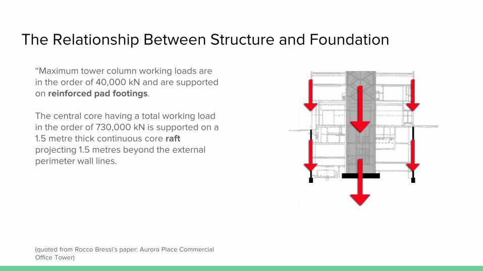
“Maximum tower column working loads are in the order of 40,000 kN and are supported on reinforced pad footings. The central core having a total working load in the order of 730,000 kN is supported on a 1.5 metre thick continuous core raft projecting 1.5 metres beyond the external perimeter wall lines. (quoted from Rocco Bressi’s paper: Aurora Place Commercial Office Tower)
The Relationship Between Structure and Foundation
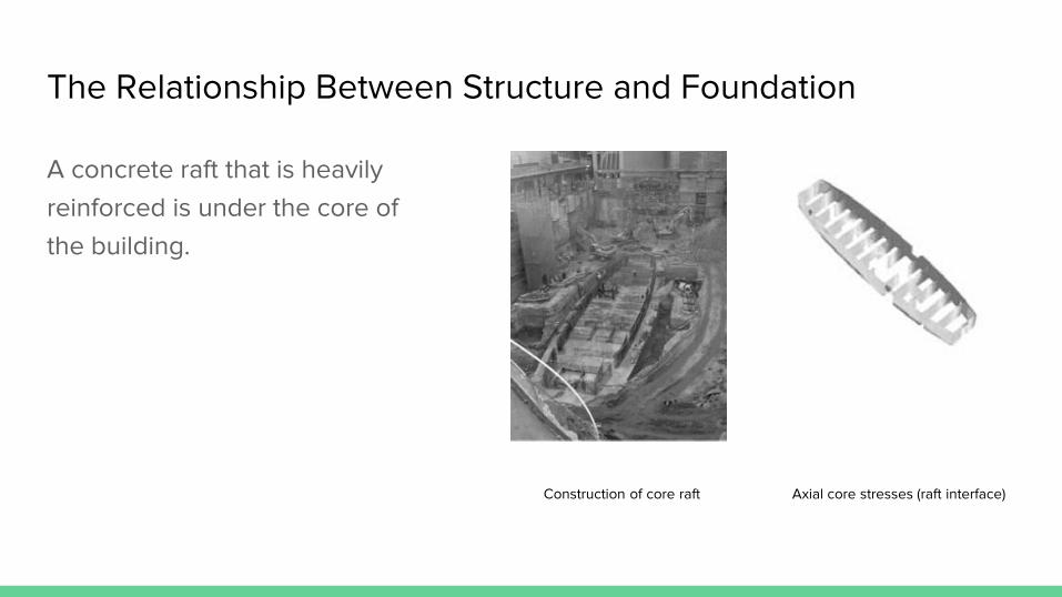
Construction of core raft Axial core stresses (raft interface)
A concrete raft that is heavily
reinforced is under the core of
the building.
The Relationship Between the Geological Features of the Site
and Foundation
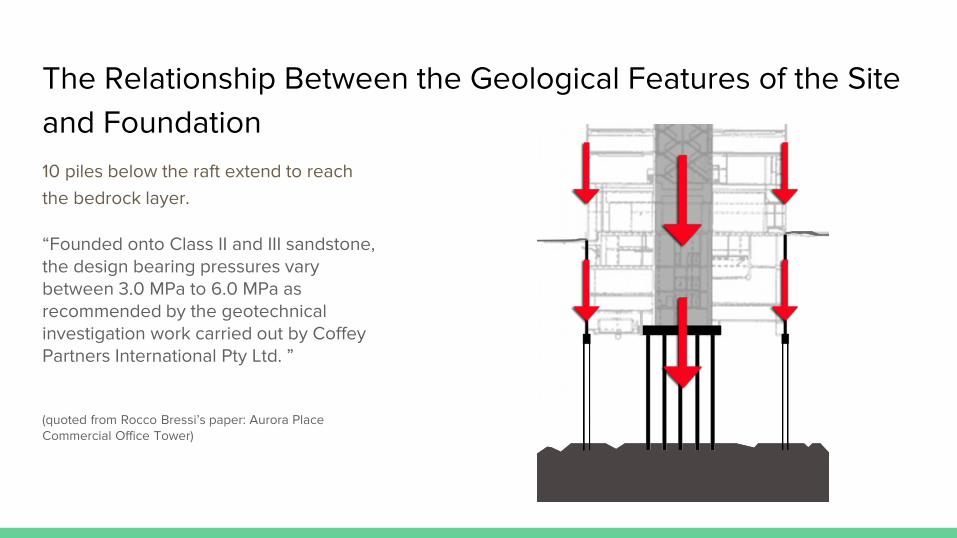
10 piles below the raft extend to reach
the bedrock layer.
“Founded onto Class II and III sandstone, the design bearing pressures vary between 3.0 MPa to 6.0 MPa as recommended by the geotechnical investigation work carried out by Coffey Partners International Pty Ltd. ” (quoted from Rocco Bressi’s paper: Aurora Place Commercial Office Tower)
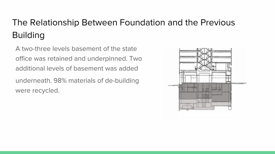
The Relationship Between Foundation and the Previous
Building
A two-three levels basement of the state
office was retained and underpinned. Two
additional levels of basement was added
underneath. 98% materials of de-building
were recycled.
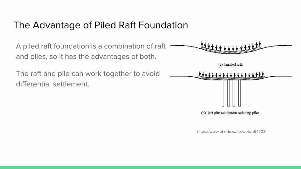
The Advantage of Piled Raft Foundation
A piled raft foundation is a combination of raft
and piles, so it has the advantages of both.
The raft and pile can work together to avoid
differential settlement.
https://www.ut.edu.sa/ar/web/u54708
Other Discussions on Aseismatic Measures in the Foundation
The 1.5meters-thick raft, the structure system of the basement, the column pad
footings, and the piles may have ductile reinforcing steel in it so that damping
action is achieved.
In general, except the strength of structural elements should meet the
requirement of National Construction Code of Australia, ductility of structural
members should be achieved in order to cope with earthquake inertial forces.
Loading Analysis
1. Vertical Loading Analysis
2. Core Jump Form System Construction
3. Lateral Loading Analysis

Vertical load analysis
Loads travel through the steel beam ( the thickened slab section) out to the core and the perimeter columns.
The vertical loads are distributed on each floor.
The shearing walls of the core and the columns transfer the loads to the foundation.
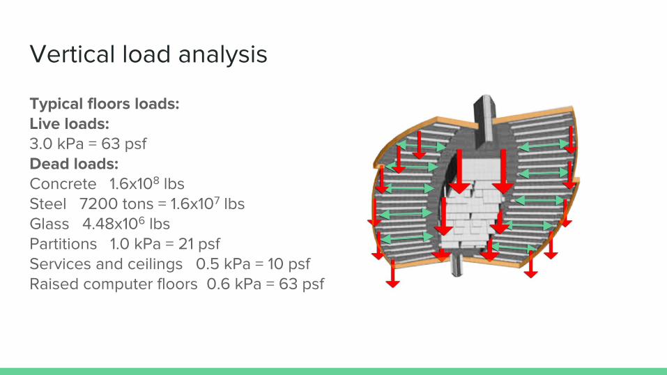
Typical floors loads: Live loads: 3.0 kPa = 63 psf Dead loads: Concrete 1.6x10⁸ lbs Steel 7200 tons = 1.6x10⁷ lbs Glass 4.48x10⁶ lbs Partitions 1.0 kPa = 21 psf Services and ceilings 0.5 kPa = 10 psf Raised computer floors 0.6 kPa = 63 psf
Vertical load analysis
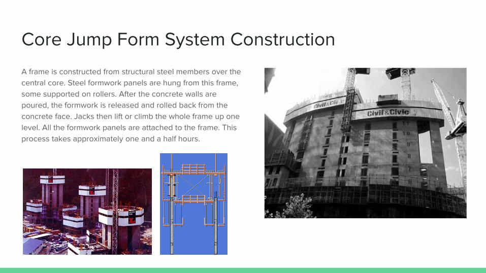
Core Jump Form System Construction
A frame is constructed from structural steel members over the
central core. Steel formwork panels are hung from this frame,
some supported on rollers. After the concrete walls are
poured, the formwork is released and rolled back from the
concrete face. Jacks then lift or climb the whole frame up one
level. All the formwork panels are attached to the frame. This
process takes approximately one and a half hours.
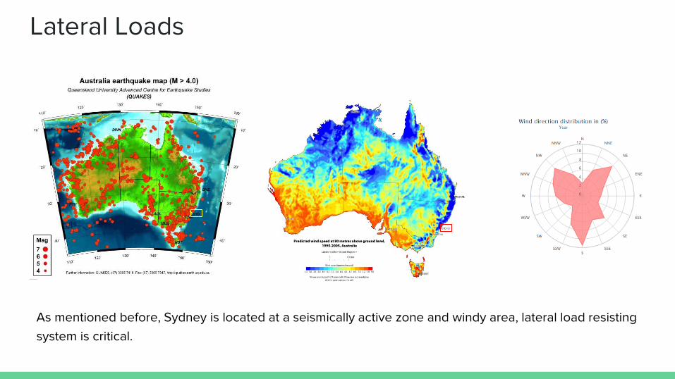
Lateral Loads
As mentioned before, Sydney is located at a seismically active zone and windy area, lateral load resisting
system is critical.
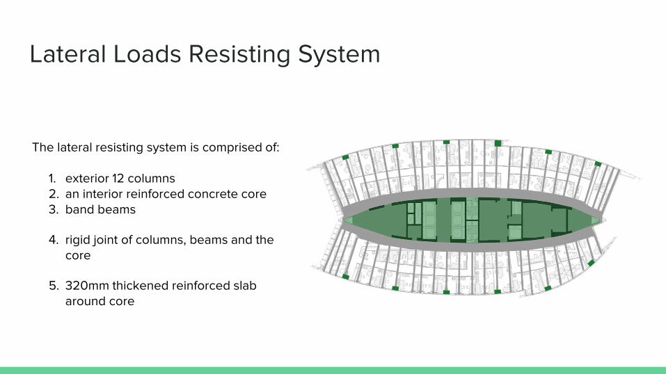
Lateral Loads Resisting System
The lateral resisting system is comprised of:
1. exterior 12 columns 2. an interior reinforced concrete core 3. band beams
4. rigid joint of columns, beams and the core
5. 320mm thickened reinforced slab around core

Lateral Loads Transfer Path
Structure components
The core
The slabs & columns
Lateral force
70%
30%
Wind loads reach the surface of the building. 30% of lateral force is transferred to the outside columns then to the foundation. 70% of the lateral force is transferred by floor slabs to the core, then taken by the piled-raft foundation.
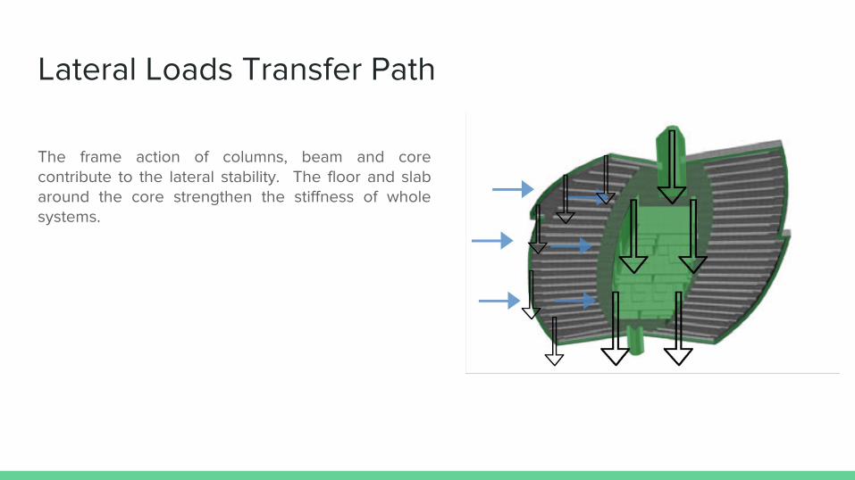
Lateral Loads Transfer Path
The frame action of columns, beam and core contribute to the lateral stability. The floor and slab around the core strengthen the stiffness of whole systems.
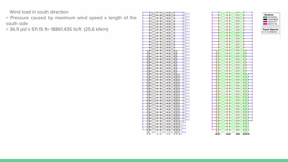
Wind load in south direction = Pressure caused by maximum wind speed x length of the south side = 36.9 psf x 511.15 ft= 18861.435 lb/ft (25.6 kN/m)

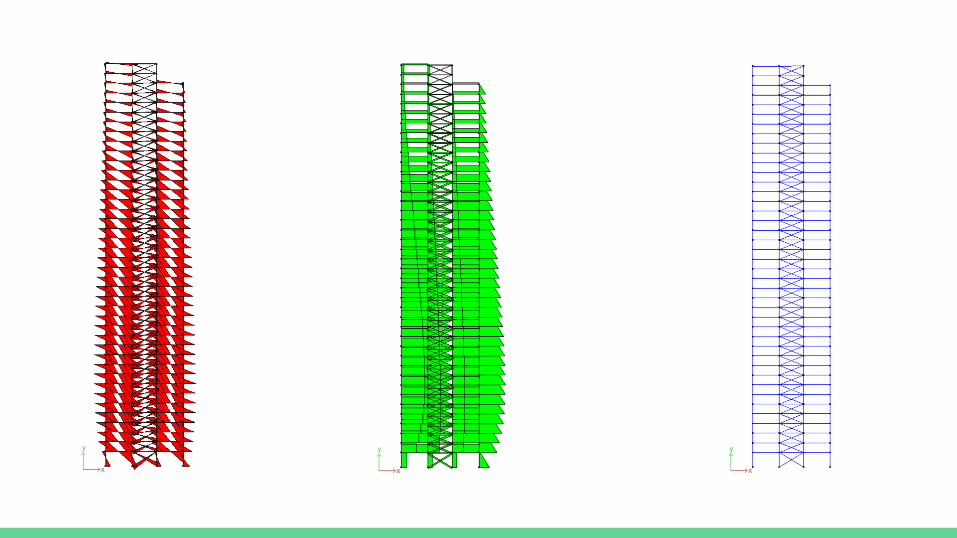
From left to right, the force in the beam changed from compression to tension. Piled-raft foundation must transfer
the horizontal force to the surrounding soil, the building tend to lift up on the left and the largest deflection
appears at the top of the building

Wind load in west direction = Pressure caused by maximum wind speed x length of the west side = 36.9 psf x 511.15 ft= 18861.435 lb/ft (25.6 kN/m)

Building Live Load
= Designed live load capacity per square foot = 63 psf
Total Dead Load
= (Glass Load + Steel Load + Concrete Load + Partitions Load + Services & Ceilings Load) /Total leasable area
= (4.162x10⁶ lbs + 15.873x10⁶ lbs + 11.08x10⁶ lbs + 5.27x 10⁶ lbs)/448,317 sf = 81.1 psf
Total Load = 63 psf + 81.1 psf =144.1 psf
144.1 psf x 511.15 ft= 73656 lb/ft (99.8 kN/m)
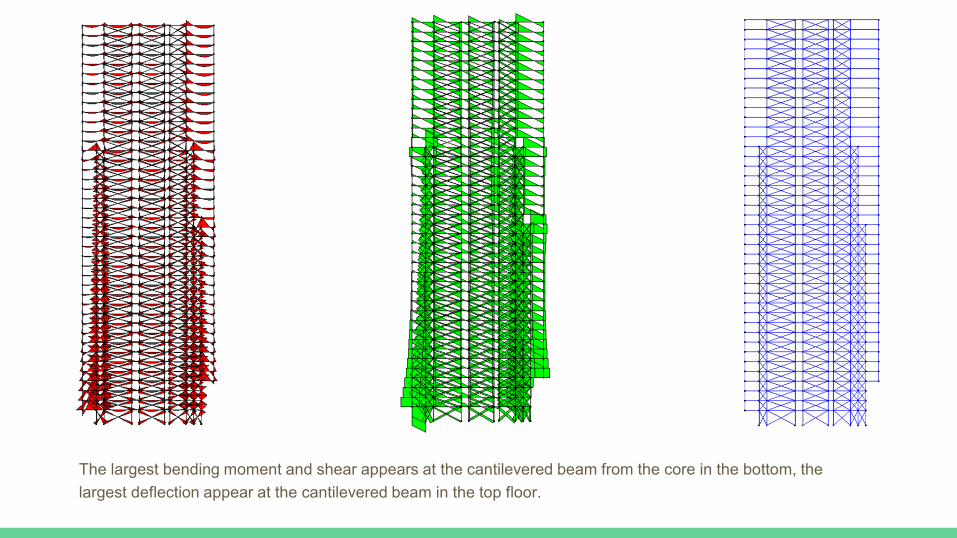
The largest bending moment and shear appears at the cantilevered beam from the core in the bottom, the
largest deflection appear at the cantilevered beam in the top floor.
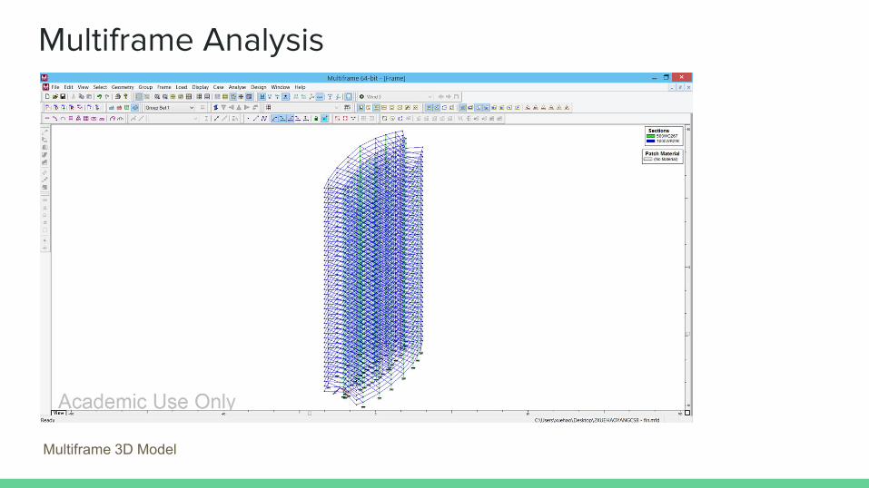
Multiframe Analysis
Multiframe 3D Model

Multiframe Analysis (wind load)
Wind velocity of 15m/s from south direction
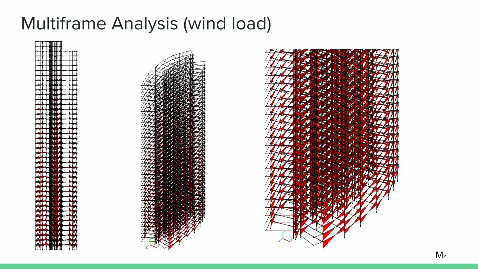
Multiframe Analysis (wind load)
MZ
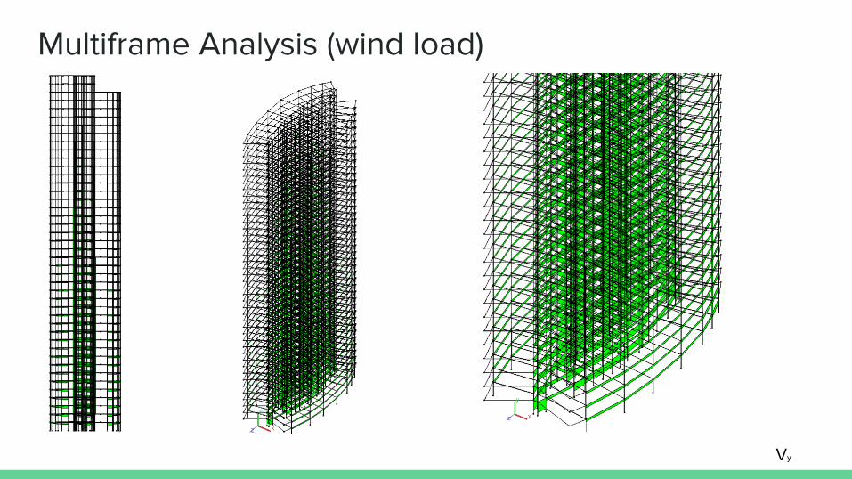
Multiframe Analysis (wind load)
Vy
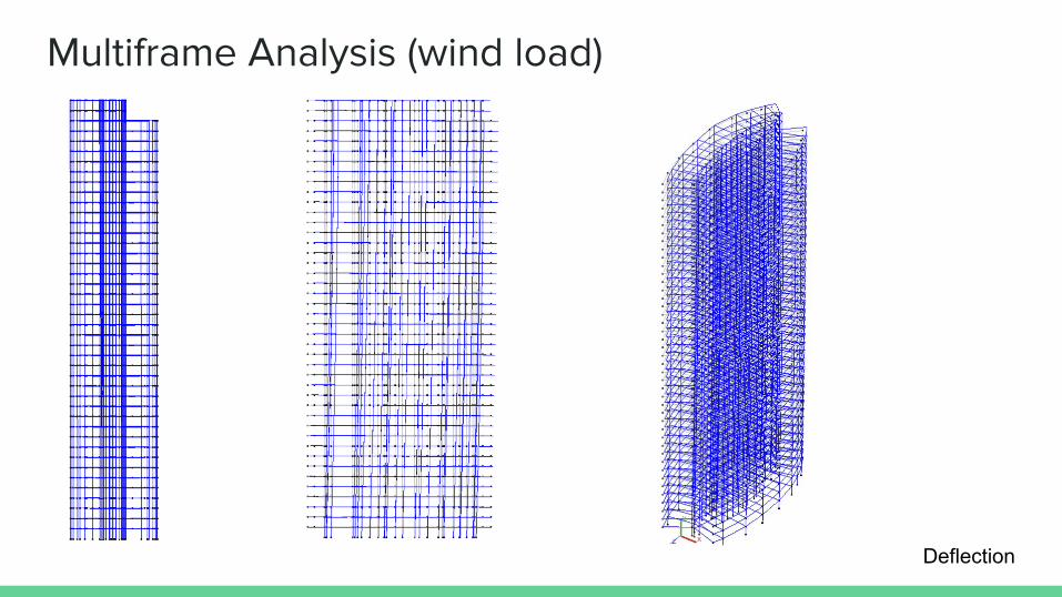
Multiframe Analysis (wind load)
Deflection

Bibliography Books:
Aurora Place, Renzo Piano; Published in Australia and New Zealand in 2001; The Watermark Press Pty Limited, Sydney Australia:
Copyright text: Andrew Metclaf
Renzo Piano Building Workshop Volume IV; Peter Buchnan, 2000 Phiadon Press Limited; and Volume V, Peter Buchnan, 2008 Phaidon
Press Limited
https://sites.google.com/site/ae390auroraplace/structural-analysis/drawings-diagrams
http://www.beaufort-analysis.com/Civil.htm
http://ctbuh.org/Portals/0/Repository/Bressi_2001_AuroraPlaceCommercialTower.6b110d80-43cc-4c40-b2fb-1fecce667c45.pdf
http://www.fondazionerenzopiano.org/project/95/aurora-place/images/page/3/
http://www.fondazionerenzopiano.org/project/95/aurora-place/drawings/page/3/
http://innovarchiarchitects.com/aurora-place/
http://architectureau.com/articles/award-for-commercial-buildings-3/

THANKS!