Embed Size (px)
Citation preview
ARCH 631 Note Set 21.3 F2015abn
439
Examples:
Steel
Example 1 (AISC Design Examples vV13.0)
Select a W18x50 from Table 3-2. Determined the required flexural strength with the self weight.
LRFD ASD
wu-s.w. = 1.2(0.050 kip/ft) = 0.06 kip/ft
kip/ft 2kip ft kip ft0.06 (35.0 ft)
266 275.28
u adjustedM − −
− = + =
wu-s.w. = 0.050 kip/ft
kip/ft 2kip ft kip ft0.05 (35.0 ft)
184 191.78
u adjustedM − −
− = + =
275.2 kip-ft o.k. 191.7 kip-ft o.k.
ARCH 631 Note Set 21.3 F2015abn
440
Example 1 (continued)
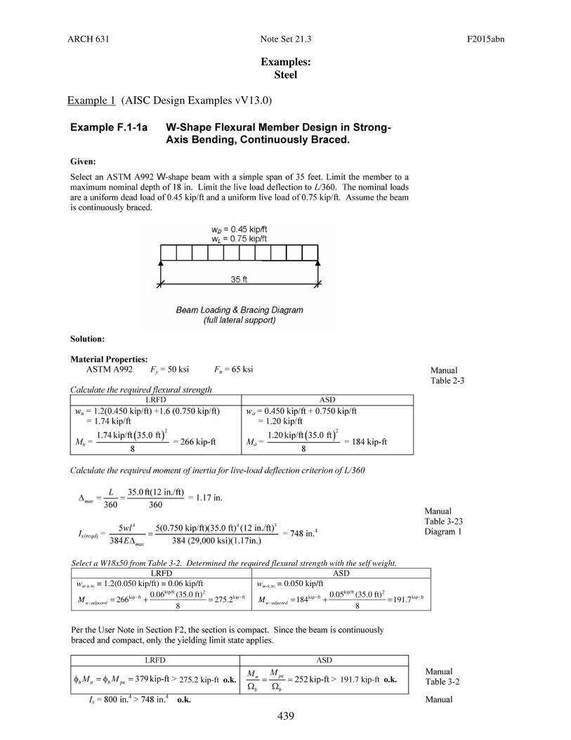
I required is in this grouping, with the W21x44 (bold) the most economical. But this section must be 18 inches maximum, and the W18 x 46 does not have enough (even though it has enough
moment capacity of 340 k-ft (φbMpx)) Look to the next section above for a W18
with I > 748 in4.
275.2 kip-ft 191.7 kip-ft
ARCH 631 Note Set 21.3 F2015abn
441
Example 1 (continued)
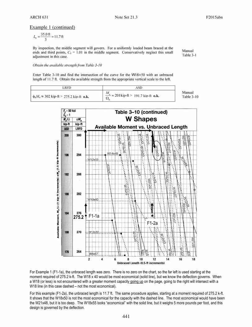
For Example 1 (F1-1a), the unbraced length was zero. There is no zero on the chart, so the far left is used starting at the moment required of 275.2 k-ft. The W18 x 40 would be most economical (solid line), but we know the deflection governs. When a W18 (or less) is not encountered with a greater moment capacity going up on the page, going to the right will intersect with a W18 line (in this case dashed – not the most economical).
For this example (F1-2a), the unbraced length is 11.7 ft. The same procedure applies, starting at a moment required of 275.2 k-ft. It shows that the W18x50 is not the most economical for the capacity with the dashed line. The most economical would have been the W21x48, but it is too deep. The W18x55 looks “economical” with the solid line, but it weighs 5 more pounds per foot, and this design is governed by the deflection.
F1-1a
F1-2a
275.2
275.2 kip-ft o.k. 191.7 kip-ft o.k.

ARCH 631 Note Set 21.3 F2015abn
442
• Top values are total factored distributed load from strength and deflection criteria.
• Values below in gray are for live load
deflection limit (unfactored).
LRFD
STANDARD LOAD TABLE FOR OPEN WEB STEEL JOISTS, K-SERIES
Based on a 50 ksi Maximum Yield Strength – Loads shown in Pounds per Linear Foot (plf)
256 288 + 72 600 + 960
+ 360 = 13,744 lbs.
256 288 + 72 600
960 660
6773
6971
(6971) 465
6971 (360+600+960) (288+72)
14.03
6971(14.03) – 360(11.03) -
960(7.03) – 600(5.03) - (288+72)(14.03)
2
48,634
(48,634) = 432.3
465
Select 18K7 for total load (502) and live load (180) and call it: 18K9SP
Example 2 (LRFD)
ARCH 631 Note Set 21.3 F2015abn
443
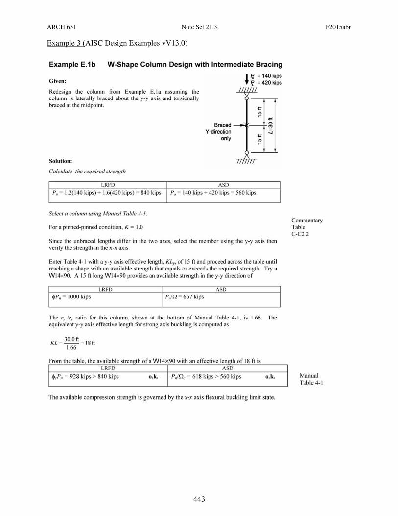
Example 3 (AISC Design Examples vV13.0)
ARCH 631 Note Set 21.3 F2015abn
444
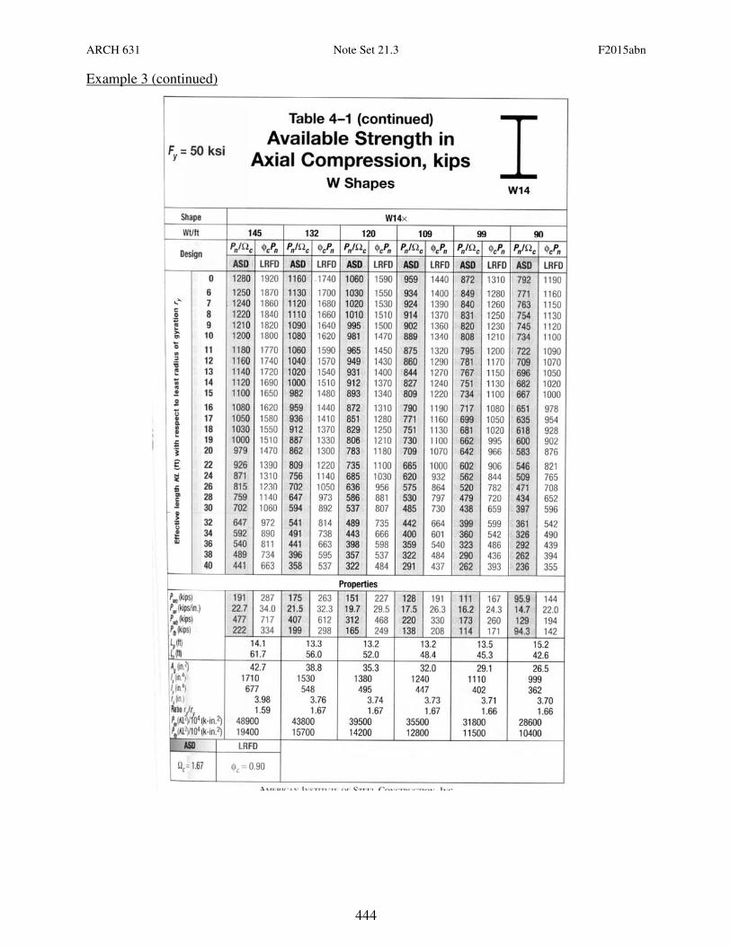
Example 3 (continued)
ARCH 631 Note Set 21.3 F2015abn
445
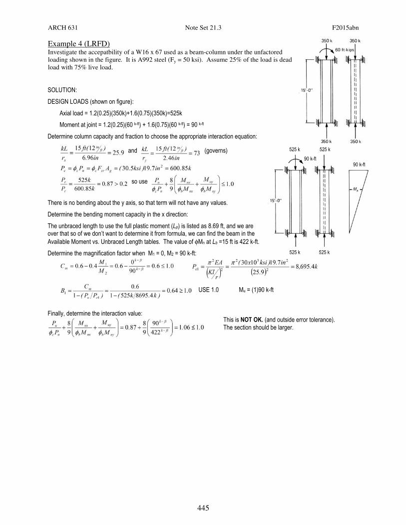
Example 4 (LRFD) Investigate the accepatbility of a W16 x 67 used as a beam-column under the unfactored
loading shown in the figure. It is A992 steel (Fy = 50 ksi). Assume 25% of the load is dead
load with 75% live load.
SOLUTION:
DESIGN LOADS (shown on figure):
Axial load = 1.2(0.25)(350k)+1.6(0.75)(350k)=525k
Moment at joint = 1.2(0.25)(60 k-ft) + 1.6(0.75)(60 k-ft) = 90 k-ft
Determine column capacity and fraction to choose the appropriate interaction equation:
and (governs)
so use
There is no bending about the y axis, so that term will not have any values.
Determine the bending moment capacity in the x direction:
The unbraced length to use the full plastic moment (Lp) is listed as 8.69 ft, and we are over that so of we don’t want to determine it from formula, we can find the beam in the
Available Moment vs. Unbraced Length tables. The value of φMn at Lb =15 ft is 422 k-ft.
Determine the magnification factor when M1 = 0, M2 = 90 k-ft:
USE 1.0 Mu = (1)90 k-ft
Finally, determine the interaction value:
525 k
This is NOT OK. (and outside error tolerance). The section should be larger.
525 k
90 k-ft 90 k-ft
525 k
525 k