Embed Size (px)
Citation preview

EVlink
se.com
Electric vehicle charging solutions
se.com/sg

The EVlink Product Range
2 | Electric vehicle charging solutions se.com
Characteristics
Power supply
• Smart Wallbox can be supplied either in single-phase or in three-phase
• 220-240 V single-phase - 50/60 Hz
• 380-415 V three-phase - 50/60 Hz
Rated charging current
• T2: 8 A to 32 A (factory setting 32 A)
Power consumption
• Power consumption of each conditional input (limitation
and deferred start): 5 mA 24 V DC
Diagram of the earthing system
• TT, TN-S, TN-C-S
• IT (may require the addition of an isolating transformer for charging of
certain vehicles)
Mechanical and environmental characteristics
• Ingress protection code: IP54
• Impact protection code: IK10
• Operating temperature: -30°C to +50°C
• Storage temperature: -40°C to +80°C
• Attached cable length: 4.5 m
Charging access
• Key locking
• User authentication through a RFID badge. Remote authentication by
supervision or local setting of authorized badges
- 13.56 MHz RFID reader for badges with chips Mifare Ultralight,
Mifare Classic 1K / 4K, I Code SLI, Tag-it HFI, EM4135 ...
(under ISO/IEC 14443 A&B, ISO/IEC 15693 protocols)Notes: RFID badges available on the market and standard are modified very often,
so we advice to carry out prior test on our charging station to check compatibility
- 5 RFID badges provided with every RFID-type charging station
Warranty
• 24 months for the entire EVlink range
Standards
• IEC/EN 61851-1 ed 2.0
• IEC/EN 61851-22 ed 1.0
• IEC/EN 62196-1 ed 2.0
• IEC/EN 62196-2 ed 1.0
Connectivity
• Wired Ethernet: 3 ports
- Port 1: LAN
- Port 2: 3G/4G
- Port 3: connection to PC for commissioning
• 3G/4G modem as an accessory
• OCPP 1.5 or OCPP 1.6 interface
Energy metering
• Integrated measuring of the apparent power
• Interface with an external MID energy meter
Commissioning
• Parameters setting through a web server embedded in the charging station.
EVlink Smart Wallbox
Cloud-connectable
Ethernet
Z.E. READY
> ROHS compliant
> Reach compliant
> EoLi: End Of Life Process
> Product Environmental Profile
compliant
Certification
EVlink Smart Wallbox has
obtained the CB test certificate
issued by the LCIE test laboratory,
establishing compliance with the
IEC 61851-1 and IEC 61851-22
standards.

se.com Electric vehicle charging solutions | 3
Charging station references
EVlink Smart Wallbox
TR25:2016 ComplianceDescription Socket outlet or
connector type
Charging
access
Power (kW)(1)
Phases
References
With attached cable 4.5 m, on right side - Silver plated contacts
T2 Key 7.4 (1P) EVB1A7PCKI
RFID (2) 7.4 (1P) EVB1A7PCRI
T2 Key 22 (3P) EVB1A22PCKI
RFID (2) 22 (3P) EVB1A22PCRI
(1) Factory setting: 32 A - and all RFID badges validated.
Can be replaced by customer setting (16 A, list of RFID badges…) using a PC via embedded webserver (see commissioning guide DOCA0060).
(2) Includes 5 RFID badges.
Protective
devices
Protective devices and optional equipment
Description
Charging Single-phase Three-phase
Rated Power - Current 7.4 kW - 32 A (4) 22 kW - 32 A (4)
Protection
Circuit breaker (overcurrent)(1) 40 A Curve C: A9F74240 40 A Curve C: A9F74440RCD (residual current)(1) 30 mA B Type for EV (2): A9Z51240 30 mA B Type for EV: A9Z51440
30 mA A Type: A9R51240 30 mA A Type: A9R51440Under voltage tripping auxilary with iC60 A9A26969 (3) A9A26969 (3)
with DT40 A9N26969 (3) A9N26969 (3)
Deferred start
Relay With normally open contact (5)
Load-shedding
Relay With normally open contact (5)
(1) References to be defined and local availability to be checked by Schneider Electric front offices.(2) In accordance with the electrical installation standard HD 60364-7-722:2016. Refer to local regulation.(3) Necessary to meet EV Ready requirements.(4) Without or with domestic socket.(5) Smart Wallbox setting can be changed to "normally closed" if necessary, with commissioning tool.
New installation: supply line and protection devices must be defined for the highest power setting.
The charging station operates autonomously.
It has a dedicated protective device.
Installation: by an electrician
Location: residential, private usage
The EVlink Product Range
4 | Electric vehicle charging solutions se.com
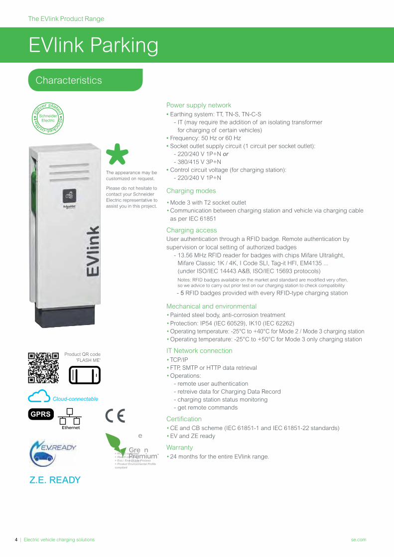
EVlink Parking
Power supply network
• Earthing system: TT, TN-S, TN-C-S
- IT (may require the addition of an isolating transformer
for charging of certain vehicles)
• Frequency: 50 Hz or 60 Hz
• Socket outlet supply circuit (1 circuit per socket outlet):
- 220/240 V 1P+N or
- 380/415 V 3P+N
• Control circuit voltage (for charging station):
- 220/240 V 1P+N
Charging modes
•Mode 3 with T2 socket outlet
• Communication between charging station and vehicle via charging cable
as per IEC 61851
Charging access
User authentication through a RFID badge. Remote authentication by
supervision or local setting of authorized badges
- 13.56 MHz RFID reader for badges with chips Mifare Ultralight,
Mifare Classic 1K / 4K, I Code SLI, Tag-it HFI, EM4135 ...
(under ISO/IEC 14443 A&B, ISO/IEC 15693 protocols)
Notes: RFID badges available on the market and standard are modified very often,
so we advice to carry out prior test on our charging station to check compatibility
- 5 RFID badges provided with every RFID-type charging station
Mechanical and environmental
•Painted steel body, anti-corrosion treatment
•Protection: IP54 (IEC 60529), IK10 (IEC 62262)
• Operating temperature: -25°C to +40°C for Mode 2 / Mode 3 charging station
•Operating temperature: -25°C to +50°C for Mode 3 only charging station
IT Network connection
•TCP/IP
•FTP, SMTP or HTTP data retrieval
•Operations:
- remote user authentication
- retreive data for Charging Data Record
- charging station status monitoring
- get remote commands
Certification
•CE and CB scheme (IEC 61851-1 and IEC 61851-22 standards)
•EV and ZE ready
Warranty
•24 months for the entire EVlink range.
Characteristics
Cloud-connectable
Ethernet
Product QR code
'FLASH ME'
Z.E. READY
The appearance may be
customized on request.
Please do not hesitate to
contact your Schneider
Electric representative to
assist you in this project.
> ROHS compliant
> Reach compliant
> EoLi: End Of Life Process
> Product Environmental Profile
compliant

se.com Electric vehicle charging solutions | 5
Charging station references
EVlink ParkingTR25:2016 Compliance
Charging
station type
No. of
chargepoints
Socket outlet type
Silver-plated contacts
Power per socket outlet / Phases
7.4 kW (1P - 32 A) 22 kW (3P - 32 A)With RFID reader (2)
2T2 with shutters EVF2S22P44R
(1) On the right side of the charging station.
(2) Includes 5 RFID badges.
Mode 3
With
RFID reader

The EVlink Product Range
6 | Electric vehicle charging solutions se.com
EVlink AC charging station testing tool
Tool for trained electriciansThis tool permits to check correct operation of an AC charging station:
•EVlink Wallbox
•EVlink Smart Wallbox
•EVlink Parking
•EVlink City
•Any charging station complying with IEC 61851-1, by simulation of
a vehicle during charging
Easy to carry
•Weight Approx. 795 g
Compatibility
•Accepts any cable fitted with a T2 connector
•Single-phase or three-phase alternating current charging
•Cable to be ordered separately; please refer to page 46.
In short
Reference: EVA1SADS
Type F
socket-outletType 2
socket
Power On indicator lights
on the L1, L2, L3 phases
Vehicle status selector
CP pilot wire measurement socket
Measurement sockets for
the protection conductor PE,
the neutral N and the L1, L2, L3 phases
Charging cable rating selector
Perfectly simple… Once the testing tool is connected to the charging station, charging is
started thanks to a button. A few minutes is all that's needed to check
correct charging station operation
… and standalonePower supply via the charging cable. No internal battery, so unlimited
time for servicing operations and for you peace of mind
Possible Checks and measurementsa. Check voltage presence on each phase
b. Measure the voltage between phases, between phase and neutral,
between neutral and ground
c. Check the ground continuity
d. Test the ground fault circuit interruption capacity of the charging
station
e. Measure the voltage between the CP pilot wire and the ground
f. Observe the signals transmitted on the CP pilot wire.
NEW

se.com Electric vehicle charging solutions | 7
Characteristics of the power supply network
•The testing tool is powered via the charging current
•Network frequency: 50 Hz
•Earthing system: TT or TN (do not use in IT)
•Voltage: 400 Va on type 2 connector
•Power: test consumer Max. 2.9 kVA (no continuous operation!)
Mechanical and environmental characteristics
•Degree of protection (as per IEC 60529): IP20
•Dimensions (H x L x D): complete with connector plug: 105 x 750 x 62 mm
•Weight: approx. 795 g
•Connector: Type 2 inlet • IEC 62196 type 2-II • U: 400V3~ • F: 50 Hz
•Storage temperature: -25°C / +60°C
•Operating temperature: -10°C / +45°C
•Risk of mechanical damage to the testing tool if dropped at
a temperature < -2°C
•Relative humidity rate (RH): < Max. 80%, condensation ruled out
Accessories and documents included
• Instruction guide
•Detailed user manual (to be downloaded from the Web)
Certification
The AC charging station testing tool complies with standards IEC 61010-1
and IEC 61851-1
Recommended measuring instruments for additional tests
• Operations b, c, d, e, f, require the use of measuring instruments
(multimeter, ground fault circuit interrupter tester, oscilloscope)
not supplied with the EVlink testing tool
• For observation of signals during the electric vehicle status simulation test
(signals in accordance with the IEC 61851 standard).
Characteristics

The EVlink Product Range
8 | Electric vehicle charging solutions se.com
References No. of phases Charging power accepted (kW) Cable length
1 3 3.7 7.4 11 22 (m)
T1 T2
EVP1CNS32121 5
EVP1CNL32121 7
EVP1CNX32121 10
T2 T2
EVP1CNS32122 5
EVP1CNL32122 7
EVP1CNX32122 10
EVP1CNS32322 5
EVP1CNL32322 7
EVP1CNX32322 10
EVlink cables
Characteristics
Type 1 (T1) Type 2 (T2)
• Tested and certified product: Third-part
laboratory CB certification (LCIE) complies
with applicable standard IEC 62196
• High protection, fast charging (Mode 3)
• High-strength cable
EVlink cable for charging stations:
Mobility within arm's reach
Which EVlink cable
for which electric vehicle?
Type 1 Type 2
or
Type 2
Electric vehicle inlet
Charging
station
power
socket
outlet
Characteristics
•Length: available in 5, 7 and 10 m
•Max. current: 32 A
•Operating temperature: -30°C to +50°C
•Degree of protection: IP44.
Two good reasons to have a second
EVlink cable in your electric vehicle
1
To take advantage of
the charging capacity
of public charging
stations: by having
an appropriate EVlink
cable for the charging
stations used, you
obtain fast charging
with high protection.
2
To have a fallback
solution.
E.g.: charging cable
damaged or misplaced,
help out another electric
vehicle user.

Managing the Charging Station Energy
9 | Electric vehicle charging solutions se.com
EVlink Load Management System
EVlink Load Management System (EVlink LMS) allows to monitor, control and
maximize EV charging based on the real-time available power in the building.
It ensures the respect of cost and energy efficiency constraints of a set
of charging stations by controlling their operation. The controller runs its
management program according to the selected parameters and data
received from the charging stations.
Characteristics
•PLC type: Magelis iPC lloT Edge Box Core
•Operating system: Linux Yocto
•Supply voltage: 12...24 V DC
• Inrush current: 0.43 A
•Consumption: 16 W
•Dimensions: 150 x 46 x 157 mm
•Protection class: IP40
•Compliance with directives:
- 2014/30/EU (electromagnetic compatibility)
- 2014/35/EU (Low Voltage Directive)
- Class A EN 55022 (electromagnetic compatibility, conducted and
radiated emissions)
•Connections: 2 x USB 2.0, 1 x HDMI, 2 x Ethernet (10/100/1000 Mb/s),
1 x COM RS-232 (default), RS-232/422/485 (non-isolated), 1 ground
connection, 1 x GPIO, 1 power supply connector 24 V DC
Functions
•Calculates the power allocated to the charging stations
•Ensures the centralization and availability of data for each station
Connection to the charging stations
•Directly to the Ethernet LAN via a switch
External network connection
•Directly to the Ethernet LAN or remotely via a 3G or 4G modem
•Communication under OCPP 1.6 JSON (possible upgrade to OCPP 2.0)
User interface
EVlink LMS provides access to an ergonomic and intuitive user interface
(web server) allowing to:
• remote start / stop of a charging session
• reset or reboot a charging station
• visualize a dashboard indicating in real time the status of each charging station
• manage badges (local addition, import or export badges list) and user rights
•access and download the history of charging data by station, by badge
or aggregated for the infrastructure
•consult and download maintenance data.
Current charging sessions
Charging history of electric vehicles
EVlink LMS Load Management System
for EVlink Smart Wallbox, EVlink Parking and EVlink DC Fast Charge
EVlink Load Management System
has been awarded with the
prestigious "Solar impulse Efficient
Solution" label.
Find out
more here
To download the latest
release of the EVlink
Load Management
System software, please
scan or click on the
following QR code:

se.com Electric vehicle charging solutions | 10
EVlink LMS references
Rear viewDimensions
EVlink LMS
with Static mode(dynamic load management with STATIC
current setpoint)
EVlink LMS
with Dynamic & Static modes(dynamic load management with DYNAMIC current setpoint,
or STATIC current setpoint)
References (2) HMIBSCEA53D1ESS HMIBSCEA53D1ESM HMIBSCEA53D1EDB HMIBSCEA53D1EDS HMIBSCEA53D1EDM HMIBSCEA53D1EDL HMIBSCEA53D1EML
Features
Capacity Number of EVlink
charging stations15 50 5 15 50 100 1000 (1)
Power
management
Dynamic, with a
STATIC current
setpoint
Dynamic, with a
DYNAMIC current
setpoint
Time of use
Multi zone Maximun number
of zones1 10 2 2 10 20 200
Maximun number
of zones levels1 3 2 2 3 3 4
Other loads Power consump-
tion reporting on
other feeders
Badge
management
VIP privilege
user badge
Stations
management
VIP privilege
charging station
(1) Via the management of up to 9 slave EVlink Load Management System(2) To upgrade from a current commercial reference to a higher-level one, please consult us.
Functions performed by all commercial references of EVlink LMS
Access Management
Add, modify, delete, supervise
badges
Commissioning
Commissioning all charging
stations directly from EVlink LMS
Save & restore commissioned
configuration
Operation
Supervision through real time
dashboard and remote actions
on charging stations
Charge data report export
Maintenance report export
Connectivity
Connection with CPO supervision
(OCPP 1.6 Json)
Connection with EcoStruxure
supervision (web services) (1)
Optional: 3G/4G modem
Commissioning by Ethernet cable
(1) May require specific development
NEW
1- USB1 (USB 2.0)
2- HDMI port
3- ETH1 (10/100/1000 Mbits/s)
4- COM port RS-232/422/485
5- Ground connection pin
6- USB2 (USB 2.0)
7- GPIO
8- DC power connector
1 2 3 4 5
6 7 8

Managing the Charging Station Energy
11 | Electric vehicle charging solutions se.com
PowerLogic Power meter
Commercial reference METSEPM5320
Communication 1 Ethernet port
Accuracy class 0.5 S
Dimensions 96 x 96 x 72 mm (H x W x D)
Consumption 130 mA / 24 V DC - 65 mA / PoE 48 V DC
To be completed with (not provided)
•a closed Current Transformer
•a cut-off device
•a short-circuiting block
Metering solutions
Standalone meters with external current transformers
Modbus – Ethernet Link 150 gateway
Commercial reference EGX150
Ethernet communication 2 Ethernet ports type 10/100 Base TX protocol:
HTTP, Modbus TCP/IP, FTP, SNMP
Serial communication 2 serial ports (RS232 or RS485, 2 or 4 wires)
Modbus serial protocol
Max. no. of devices: 32 directly (or 247 indirectly)
Power supply 24 V DC or PoE (15 W class 3)
Consumption 130 mA / 24 V DC - 65 mA / PoE 48 V DC
Width 8 x 9 mm modules
Operating temperature -25°C to +70°C
iEM Energy meters
Commercial reference A9MEM3255 A9MEM3555
Allocation of costs MID class C -
Communication Modbus Modbus
Class of accuracy 0.5 S with TI 5 A, 0.5 S
1 with TI 1 A
Width 5 x 18 mm modules 5 x 18 mm modules
To be completed with
(not provided)
Closed current
transformers
Rogowski current
transformers
a cut-off device
a short-circuiting block
a Link 150 gateway
METSEPM5320
A9MEM3255 A9MEM3555
EGX150
se.com Electric vehicle charging solutions | 12
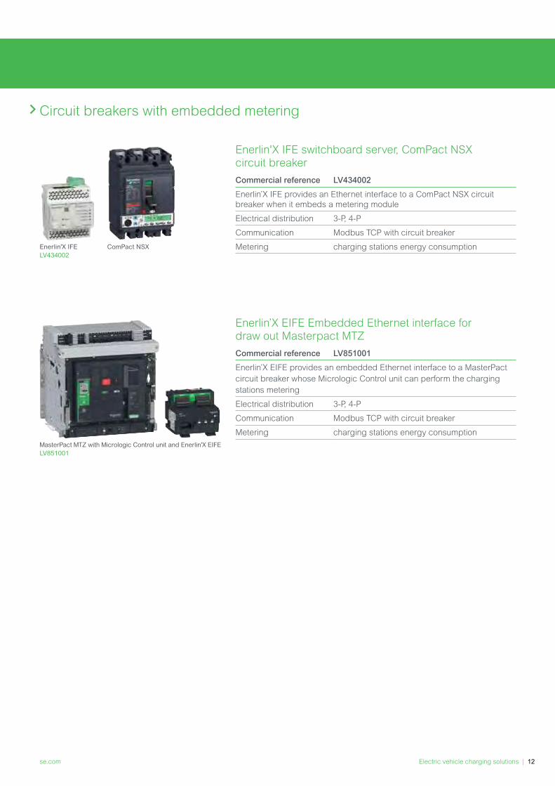
Enerlin'X IFE switchboard server, ComPact NSX circuit breaker
Commercial reference LV434002
Enerlin’X IFE provides an Ethernet interface to a ComPact NSX circuit
breaker when it embeds a metering module
Electrical distribution 3-P, 4-P
Communication Modbus TCP with circuit breaker
Metering charging stations energy consumption
Circuit breakers with embedded metering
Enerlin’X EIFE Embedded Ethernet interface for draw out Masterpact MTZ
Commercial reference LV851001
Enerlin’X EIFE provides an embedded Ethernet interface to a MasterPact
circuit breaker whose Micrologic Control unit can perform the charging
stations metering
Electrical distribution 3-P, 4-P
Communication Modbus TCP with circuit breaker
Metering charging stations energy consumption
Enerlin'X IFE
LV434002
ComPact NSX
MasterPact MTZ with Micrologic Control unit and Enerlin'X EIFE
LV851001
EVlink Electrical distribution
13 | Electric vehicle charging solutions se.com
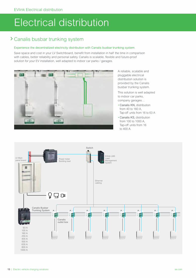
Electrical distribution
Canalis busbar trunking system
A reliable, scalable and
pluggable electrical
distribution solution is
provided by the Canalis
busbar trunking system.
This solution is well adapted
to indoor car parks,
company garages…
•Canalis KN, distribution
from 40 to 160 A,
Tap-off units from 16 to 63 A
•Canalis KS, distribution
from 100 to 1000 A,
Tap-off units from 16
to 400 A.
63 A
100 A
160 A
250 A
400 A
500 A
630 A
800 A
1000 A
Switch
LV Main
panel boardPower meterBuilding load
Ethernet cabling
EVlink LMSLoadManagementSystem
Canalis Busbar Trunking System
Canalis outlet box
Experience the decentralized electricity distribution with Canalis busbar trunking system.
Save space and cost in your LV Switchboard, benefit from installation in half the time in comparison
with cables, better reliability and personal safety. Canalis is scalable, flexible and future-proof
solution for your EV installation, well adapted to indoor car parks / garages.
se.com Electric vehicle charging solutions | 14
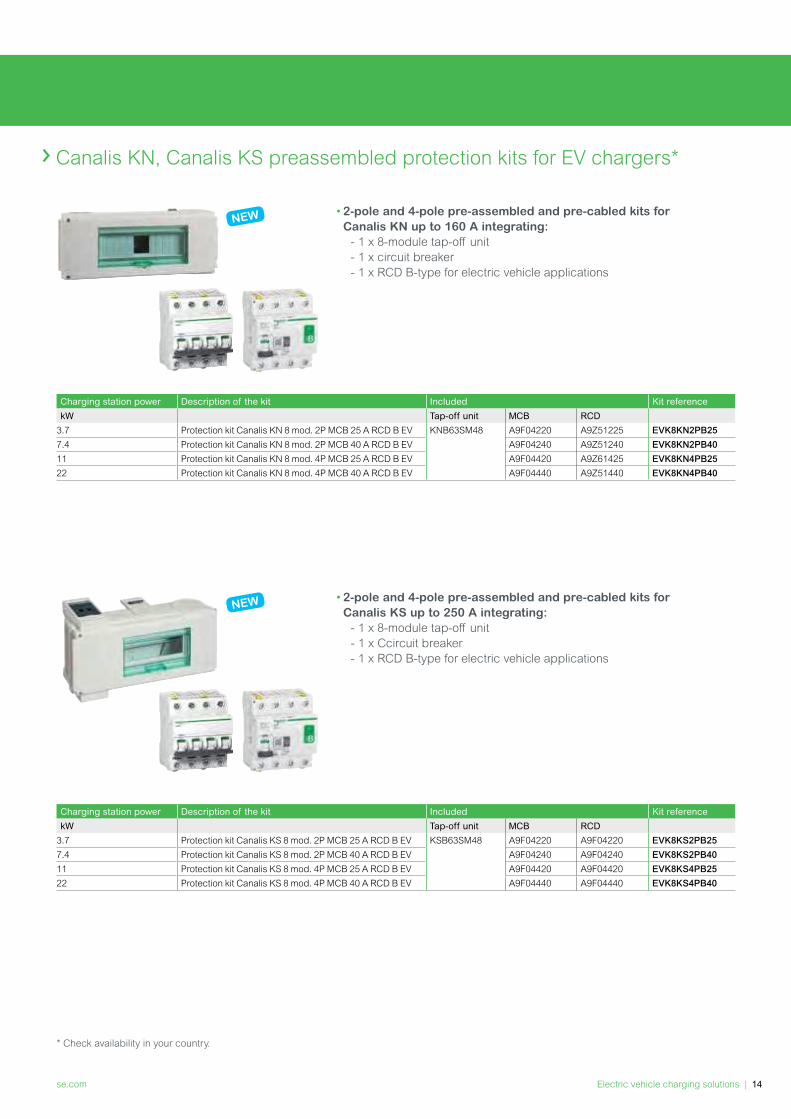
Canalis KN, Canalis KS preassembled protection kits for EV chargers*
•2-pole and 4-pole pre-assembled and pre-cabled kits for
Canalis KN up to 160 A integrating:
- 1 x 8-module tap-off unit
- 1 x circuit breaker
- 1 x RCD B-type for electric vehicle applications
•2-pole and 4-pole pre-assembled and pre-cabled kits for
Canalis KS up to 250 A integrating:
- 1 x 8-module tap-off unit
- 1 x Ccircuit breaker
- 1 x RCD B-type for electric vehicle applications
Charging station power Description of the kit Included Kit reference
kW Tap-off unit MCB RCD
3.7 Protection kit Canalis KN 8 mod. 2P MCB 25 A RCD B EV KNB63SM48 A9F04220 A9Z51225 EVK8KN2PB25
7.4 Protection kit Canalis KN 8 mod. 2P MCB 40 A RCD B EV A9F04240 A9Z51240 EVK8KN2PB40
11 Protection kit Canalis KN 8 mod. 4P MCB 25 A RCD B EV A9F04420 A9Z61425 EVK8KN4PB25
22 Protection kit Canalis KN 8 mod. 4P MCB 40 A RCD B EV A9F04440 A9Z51440 EVK8KN4PB40
Charging station power Description of the kit Included Kit reference
kW Tap-off unit MCB RCD
3.7 Protection kit Canalis KS 8 mod. 2P MCB 25 A RCD B EV KSB63SM48 A9F04220 A9F04220 EVK8KS2PB25
7.4 Protection kit Canalis KS 8 mod. 2P MCB 40 A RCD B EV A9F04240 A9F04240 EVK8KS2PB40
11 Protection kit Canalis KS 8 mod. 4P MCB 25 A RCD B EV A9F04420 A9F04420 EVK8KS4PB25
22 Protection kit Canalis KS 8 mod. 4P MCB 40 A RCD B EV A9F04440 A9F04440 EVK8KS4PB40
* Check availability in your country.
NEW
NEW

Schneider Electric SE
35, rue Joseph Monier
CS 30323
92506 Rueil Malmaison Cedex
France
July, 2020
Document Number COM-POWER-VE-CA3-EN
© 2020 - Schneider Electric. All Rights Reserved.
All trademarks are owned by Schneider Electric SE or its affiliated companies. This document has been
printed on recycled paper
Singapore 33950550 Kallang Avenue
Home and Distribution Email: [email protected] Care Center: (+65) 6464 7887Customer Care email: [email protected] Connect with us: facebook.com/schneiderElectricSG
July, 2020
Schneider Electric Singapore Pte Ltd


