Embed Size (px)
Citation preview
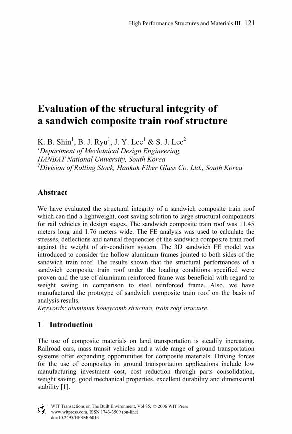
Evaluation of the structural integrity of a sandwich composite train roof structure
K. B. Shin1, B. J. Ryu1, J. Y. Lee1 & S. J. Lee2 1Department of Mechanical Design Engineering, HANBAT National University, South Korea 2Division of Rolling Stock, Hankuk Fiber Glass Co. Ltd., South Korea
Abstract
We have evaluated the structural integrity of a sandwich composite train roof which can find a lightweight, cost saving solution to large structural components for rail vehicles in design stages. The sandwich composite train roof was 11.45 meters long and 1.76 meters wide. The FE analysis was used to calculate the stresses, deflections and natural frequencies of the sandwich composite train roof against the weight of air-condition system. The 3D sandwich FE model was introduced to consider the hollow aluminum frames jointed to both sides of the sandwich train roof. The results shown that the structural performances of a sandwich composite train roof under the loading conditions specified were proven and the use of aluminum reinforced frame was beneficial with regard to weight saving in comparison to steel reinforced frame. Also, we have
analysis results. Keywords: aluminum honeycomb structure, train roof structure.
1 Introduction
The use of composite materials on land transportation is steadily increasing. Railroad cars, mass transit vehicles and a wide range of ground transportation systems offer expanding opportunities for composite materials. Driving forces for the use of composites in ground transportation applications include low manufacturing investment cost, cost reduction through parts consolidation, weight saving, good mechanical properties, excellent durability and dimensional stability [1].
High Performance Structures and Materials III 121
manufactured the prototype of sandwich composite train roof on the basis of
doi:10.2495/HPSM06013
© 2006 WIT PressWIT Transactions on The Built Environment, Vol 85, www.witpress.com, ISSN 1743-3509 (on-line)
The reduction of structural weight of one large component usually triggers positive synergy effects for other parts of the vehicle. For example, a reduction of the mass of a railway carbody could lead to weight savings in the traction system, suspension, brakes and other subsystems. The manufacturing technologies for steel or aluminum carbodies of railway rolling stocks are currently highly developed. Additionally, cost and weight savings and the increase of availability of the rolling stock are difficult to achieve using the conventional metal materials. Therefore, the use of sandwich composite materials for the railway carriage structure has been proposed and recommended in transportation applications because they offer not only high specific stiffness and strength but also low manufacturing investment cost as compared to other conventional materials [2]. Recently, composites have been applied for the lightweight design of the train roof structure, side structure and carbody shell structure. A prototype composite train roof was developed to find a lightweight, cost saving solution to large structural components for rail vehicles. Additionally, a composite roof structure improves on torsion stiffness of a railway carbody [3]. Other advantages included: (1) reduced production costs, (2) reduced part count, (3) elimination of an additional thermal insulation, (4) improved passenger comfort. ‘Turbostar’ in the UK, ‘PUMA’ Train Express in Germany and ‘RARe-520’ in Switzerland are good examples. These examples applied advanced composite material to train roof structure. The objectives of this paper are as following: (1) Evaluation of the structural integrity of developing sandwich composite train roof structure, (2) Manufacturing the prototype of sandwich composite train roof on the basis of analysis results.
2 Design of the lightweight composite train roof structure
2.1 Structure design
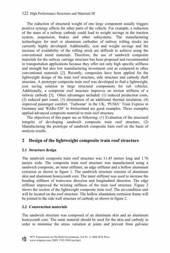
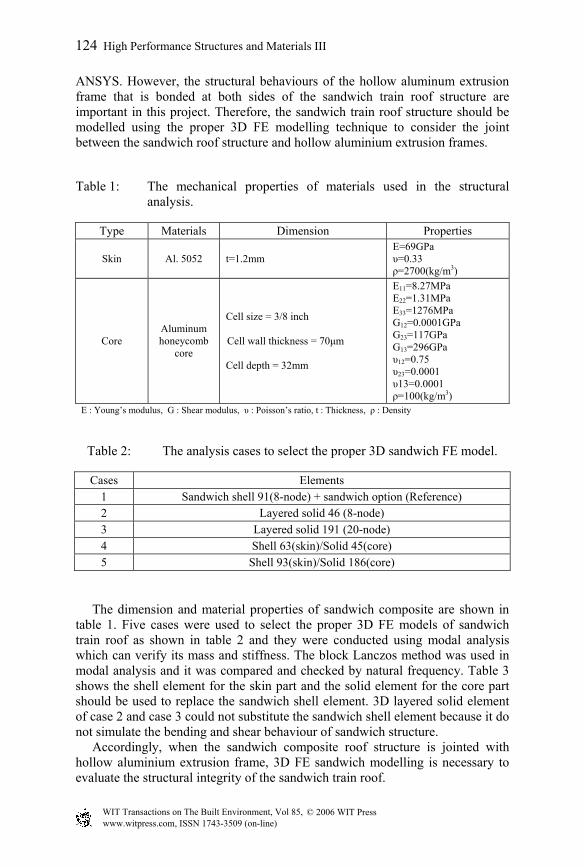
The sandwich composite train roof structure was 11.45 meters long and 1.76 meters wide. The composite train roof structure was manufactured using a sandwich composite, an inner stiffener, an edge stiffener and a hollow aluminum extrusion as shown in figure 1. The sandwich structure consists of aluminum skin and aluminum honeycomb core. The inner stiffener was used to increase the bending stiffness of transverse direction and longitudinal direction. The edge stiffener improved the twisting stiffness of the train roof structure. Figure 2 shows the section of the lightweight composite train roof. The air-condition unit will be located on the roof structure. The hollow aluminium extrusion frame will be jointed to the side wall structure of carbody as shown in figure 2.
2.2 Construction materials
The sandwich structure was composed of an aluminum skin and an aluminum honeycomb core. The same material should be used for the skin and carbody in order to minimise the stress variation at joints and prevent from galvanic
122 High Performance Structures and Materials III
© 2006 WIT PressWIT Transactions on The Built Environment, Vol 85, www.witpress.com, ISSN 1743-3509 (on-line)
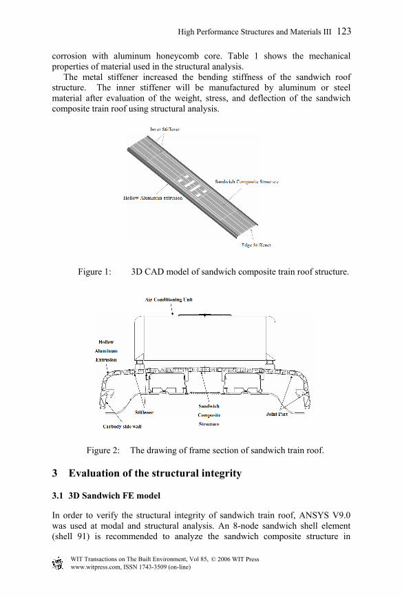
corrosion with aluminum honeycomb core. Table 1 shows the mechanical properties of material used in the structural analysis. The metal stiffener increased the bending stiffness of the sandwich roof structure. The inner stiffener will be manufactured by aluminum or steel material after evaluation of the weight, stress, and deflection of the sandwich composite train roof using structural analysis.
Figure 1: 3D CAD model of sandwich composite train roof structure.
Figure 2: The drawing of frame section of sandwich train roof.
3 Evaluation of the structural integrity
3.1 3D Sandwich FE model
In order to verify the structural integrity of sandwich train roof, ANSYS V9.0 was used at modal and structural analysis. An 8-node sandwich shell element (shell 91) is recommended to analyze the sandwich composite structure in
High Performance Structures and Materials III 123
© 2006 WIT PressWIT Transactions on The Built Environment, Vol 85, www.witpress.com, ISSN 1743-3509 (on-line)
ANSYS. However, the structural behaviours of the hollow aluminum extrusion frame that is bonded at both sides of the sandwich train roof structure are important in this project. Therefore, the sandwich train roof structure should be modelled using the proper 3D FE modelling technique to consider the joint between the sandwich roof structure and hollow aluminium extrusion frames.
Table 1: The mechanical properties of materials used in the structural analysis.
Type Materials Dimension Properties
Skin Al. 5052 t=1.2mm E=69GPa υ=0.33 ρ=2700(kg/m3)
Core Aluminum honeycomb
core
Cell size = 3/8 inch
Cell wall thickness = 70µm
Cell depth = 32mm
E11=8.27MPa E22=1.31MPa E33=1276MPa G12=0.0001GPa G23=117GPa G13=296GPa υ12=0.75 υ23=0.0001 υ13=0.0001 ρ=100(kg/m3)
E : Young’s modulus, G : Shear modulus, υ : Poisson’s ratio, t : Thickness, ρ : Density
Table 2: The analysis cases to select the proper 3D sandwich FE model.
Cases Elements 1 Sandwich shell 91(8-node) + sandwich option (Reference) 2 Layered solid 46 (8-node) 3 Layered solid 191 (20-node) 4 Shell 63(skin)/Solid 45(core) 5 Shell 93(skin)/Solid 186(core)
The dimension and material properties of sandwich composite are shown in table 1. Five cases were used to select the proper 3D FE models of sandwich train roof as shown in table 2 and they were conducted using modal analysis which can verify its mass and stiffness. The block Lanczos method was used in modal analysis and it was compared and checked by natural frequency. Table 3 shows the shell element for the skin part and the solid element for the core part should be used to replace the sandwich shell element. 3D layered solid element of case 2 and case 3 could not substitute the sandwich shell element because it do not simulate the bending and shear behaviour of sandwich structure. Accordingly, when the sandwich composite roof structure is jointed with hollow aluminium extrusion frame, 3D FE sandwich modelling is necessary to evaluate the structural integrity of the sandwich train roof.
124 High Performance Structures and Materials III
© 2006 WIT PressWIT Transactions on The Built Environment, Vol 85, www.witpress.com, ISSN 1743-3509 (on-line)
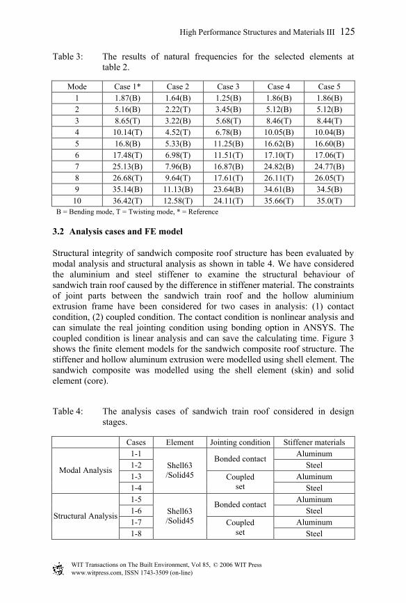
Table 3: The results of natural frequencies for the selected elements at table 2.
Mode Case 1* Case 2 Case 3 Case 4 Case 5
1 1.87(B) 1.64(B) 1.25(B) 1.86(B) 1.86(B) 2 5.16(B) 2.22(T) 3.45(B) 5.12(B) 5.12(B) 3 8.65(T) 3.22(B) 5.68(T) 8.46(T) 8.44(T) 4 10.14(T) 4.52(T) 6.78(B) 10.05(B) 10.04(B) 5 16.8(B) 5.33(B) 11.25(B) 16.62(B) 16.60(B) 6 17.48(T) 6.98(T) 11.51(T) 17.10(T) 17.06(T) 7 25.13(B) 7.96(B) 16.87(B) 24.82(B) 24.77(B) 8 26.68(T) 9.64(T) 17.61(T) 26.11(T) 26.05(T) 9 35.14(B) 11.13(B) 23.64(B) 34.61(B) 34.5(B)
10 36.42(T) 12.58(T) 24.11(T) 35.66(T) 35.0(T) B = Bending mode, T = Twisting mode, * = Reference
3.2 Analysis cases and FE model
Structural integrity of sandwich composite roof structure has been evaluated by modal analysis and structural analysis as shown in table 4. We have considered the aluminium and steel stiffener to examine the structural behaviour of sandwich train roof caused by the difference in stiffener material. The constraints of joint parts between the sandwich train roof and the hollow aluminium extrusion frame have been considered for two cases in analysis: (1) contact condition, (2) coupled condition. The contact condition is nonlinear analysis and can simulate the real jointing condition using bonding option in ANSYS. The coupled condition is linear analysis and can save the calculating time. Figure 3 shows the finite element models for the sandwich composite roof structure. The stiffener and hollow aluminum extrusion were modelled using shell element. The sandwich composite was modelled using the shell element (skin) and solid element (core).
Table 4: The analysis cases of sandwich train roof considered in design stages.
Cases Element Jointing condition Stiffener materials 1-1 Aluminum 1-2
Bonded contact Steel
1-3 Aluminum Modal Analysis
1-4
Shell63 /Solid45 Coupled
set Steel 1-5 Aluminum 1-6
Bonded contact Steel
1-7 Aluminum Structural Analysis
1-8
Shell63 /Solid45 Coupled
set Steel
High Performance Structures and Materials III 125
© 2006 WIT PressWIT Transactions on The Built Environment, Vol 85, www.witpress.com, ISSN 1743-3509 (on-line)
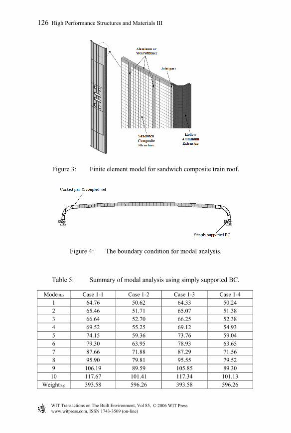
Figure 3: Finite element model for sandwich composite train roof.
Figure 4: The boundary condition for modal analysis.
Table 5: Summary of modal analysis using simply supported BC.
Mode(Hz) Case 1-1 Case 1-2 Case 1-3 Case 1-4
1 64.76 50.62 64.33 50.24
2 65.46 51.71 65.07 51.38
3 66.64 52.70 66.25 52.38
4 69.52 55.25 69.12 54.93
5 74.15 59.36 73.76 59.04
6 79.30 63.95 78.93 63.65
7 87.66 71.88 87.29 71.56
8 95.90 79.81 95.55 79.52
9 106.19 89.59 105.85 89.30
10 117.67 101.41 117.34 101.13
Weight(kg) 393.58 596.26 393.58 596.26
126 High Performance Structures and Materials III
© 2006 WIT PressWIT Transactions on The Built Environment, Vol 85, www.witpress.com, ISSN 1743-3509 (on-line)
3.3 Modal analysis
Modal analysis of the sandwich composite roof structure was conducted to evaluate its bending mode and four different cases were considered as shown in table 4. The cant side of the hollow aluminum extrusion was chosen as a boundary condition as shown in figure 4. Table 5 shows the results of natural frequencies. Bending mode only was occurred for these cases. It shows that natural frequencies of a simply supported sandwich train roof could be changed by the material of the stiffener. The changes in natural frequencies due to the material used for the stiffener can affect the whole carbody structure. If the natural frequencies of the whole carbody structure do not meet the design requirements they can be altered by changing the material of the stiffener.
3.4 Structural analysis
The objective of this chapter is to investigate the structural integrity of the sandwich composite train roof structure with the weight of air-conditioning unit (ACU). There are four cases as given in table 4.
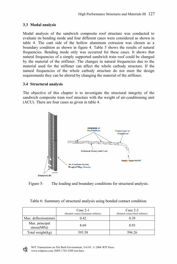
Figure 5: The loading and boundary conditions for structural analysis.
Table 6: Summary of structural analysis using bonded contact condition.
Case 2-1 (Bonded contact/Aluminum stiffener)
Case 2-2 (Bonded contact/Steel stiffener)
Max. deflection(mm) 0.42 0.39 Max. principal
stress(MPa) 8.69 8.93
Total weight(kg) 393.58 596.26
High Performance Structures and Materials III 127
© 2006 WIT PressWIT Transactions on The Built Environment, Vol 85, www.witpress.com, ISSN 1743-3509 (on-line)
3.4.1 Contact condition (case 2-1 and 2-2) A contact element was used at the joint between the sandwich composite structure and the hollow aluminum extrusion frame. An aluminum and a steel stiffener was considered in each case. Figure 5 shows the boundary and loading condition for the structural analysis. The results of structural analysis using the contact condition are given in table 6. The deflection and stress have similar results using either aluminum or steel stiffeners. The reason is that the bending stiffness of aluminium stiffener is lower than that of steel, but the weight of the aluminum stiffener is comparatively lighter than that of the steel stiffener. By using the aluminum stiffener, we can obtain a weight saving of 34% in comparison with the steel stiffener. Thus in consideration of weight reduction, the use of the aluminum stiffener can be more effective as both stiffeners are safe with regards to stiffness and strength.
3.4.2 Couple condition (case 2-3 and 2-4) The coupled condition was used at the joint, between the composite structure and the hollow aluminum extrusion frame. An aluminium and a steel stiffener was considered in each case. Table 7 shows the results of the structural analysis for the coupled condition. The results of deflection and stress for the couple condition are rather high in comparison with that of the contact condition. The reason is that the analysis of the coupled condition is linear. As with the contact condition, however, there are few differences in the results of deflection and stress depending on whether an aluminum stiffener or steel stiffener is used. When considering the effect of weight reduction, it is preferable to use aluminum stiffener.
Table 7: Summary of structural analysis using coupled condition.
Case 2-1 (Coupled set/Aluminum stiffener)
Case 2-2 (Coupled set/Steel stiffener)
Max. Deflection(mm) 0.73 0.67 Max. principal
stress(MPa) 15.89 15.83
Total weight(kg) 393.58 596.26
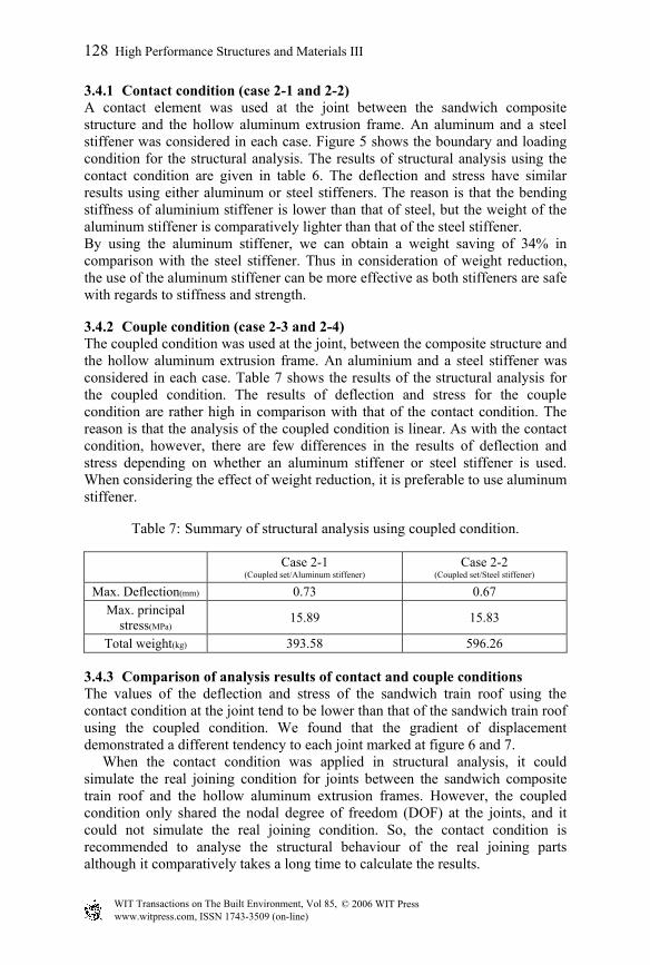
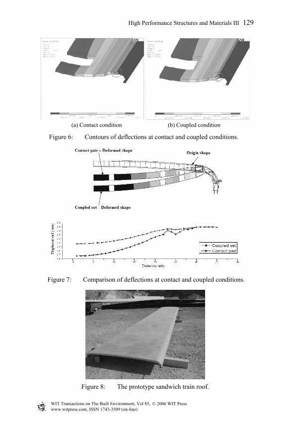
3.4.3 Comparison of analysis results of contact and couple conditions The values of the deflection and stress of the sandwich train roof using the contact condition at the joint tend to be lower than that of the sandwich train roof using the coupled condition. We found that the gradient of displacement demonstrated a different tendency to each joint marked at figure 6 and 7. When the contact condition was applied in structural analysis, it could simulate the real joining condition for joints between the sandwich composite train roof and the hollow aluminum extrusion frames. However, the coupled condition only shared the nodal degree of freedom (DOF) at the joints, and it could not simulate the real joining condition. So, the contact condition is recommended to analyse the structural behaviour of the real joining parts although it comparatively takes a long time to calculate the results.
128 High Performance Structures and Materials III
© 2006 WIT PressWIT Transactions on The Built Environment, Vol 85, www.witpress.com, ISSN 1743-3509 (on-line)
(a) Contact condition (b) Coupled condition
Figure 6:
Figure 7:
Figure 8: The prototype sandwich train roof.
High Performance Structures and Materials III 129
Contours of deflections at contact and coupled conditions.
Comparison of deflections at contact and coupled conditions.
© 2006 WIT PressWIT Transactions on The Built Environment, Vol 85, www.witpress.com, ISSN 1743-3509 (on-line)
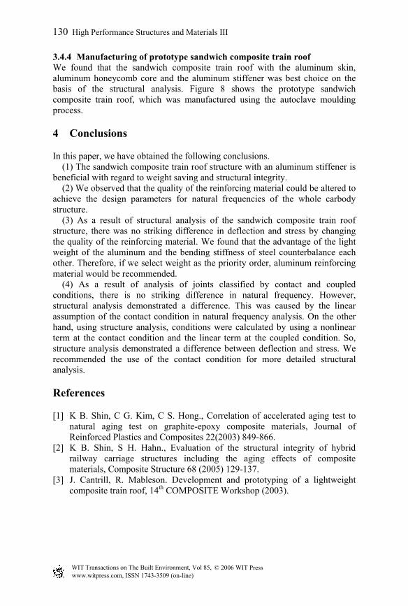
3.4.4 Manufacturing of prototype sandwich composite train roof We found that the sandwich composite train roof with the aluminum skin, aluminum honeycomb core and the aluminum stiffener was best choice on the basis of the structural analysis. Figure 8 shows the prototype sandwich composite train roof, which was manufactured using the autoclave moulding process.
4 Conclusions
In this paper, we have obtained the following conclusions. (1) The sandwich composite train roof structure with an aluminum stiffener is
beneficial with regard to weight saving and structural integrity. (2) We observed that the quality of the reinforcing material could be altered to
achieve the design parameters for natural frequencies of the whole carbody structure.
(3) As a result of structural analysis of the sandwich composite train roof structure, there was no striking difference in deflection and stress by changing the quality of the reinforcing material. We found that the advantage of the light weight of the aluminum and the bending stiffness of steel counterbalance each other. Therefore, if we select weight as the priority order, aluminum reinforcing material would be recommended.
(4) As a result of analysis of joints classified by contact and coupled conditions, there is no striking difference in natural frequency. However, structural analysis demonstrated a difference. This was caused by the linear assumption of the contact condition in natural frequency analysis. On the other hand, using structure analysis, conditions were calculated by using a nonlinear term at the contact condition and the linear term at the coupled condition. So, structure analysis demonstrated a difference between deflection and stress. We recommended the use of the contact condition for more detailed structural analysis.
References
[1] K B. Shin, C G. Kim, C S. Hong., Correlation of accelerated aging test to natural aging test on graphite-epoxy composite materials, Journal of Reinforced Plastics and Composites 22(2003) 849-866.
[2] K B. Shin, S H. Hahn., Evaluation of the structural integrity of hybrid railway carriage structures including the aging effects of composite materials, Composite Structure 68 (2005) 129-137.
[3] J. Cantrill, R. Mableson. Development and prototyping of a lightweight composite train roof, 14th COMPOSITE Workshop (2003).
130 High Performance Structures and Materials III
© 2006 WIT PressWIT Transactions on The Built Environment, Vol 85, www.witpress.com, ISSN 1743-3509 (on-line)