Embed Size (px)
Citation preview

This work is licensed under a Creative Commons Attribution-NonCommercial 3.0 Unported License
Newcastle University ePrints - eprint.ncl.ac.uk
Epshtein SA, Borodich FM, Bull SJ. Evaluation of elastic modulus and hardness
of highly inhomogeneous materials by nanoindentation. Applied Physics A
2015, 119(1), 325-335.
Copyright:
The final publication is available at Springer via http://dx.doi.org/10.1007/s00339-014-8971-5
DOI link to article:
http://dx.doi.org/10.1007/s00339-014-8971-5
Date deposited:
18/09/2015
Embargo release date:
06 February 2016

Evaluation of elastic modulus and hardness of highly inhomogeneousmaterials by indentation
Svetlana A. Epshtein1,∗, Feodor M. Borodich2,∗, and Steve J. Bull31 Laboratory of Physics and Chemistry of Coals, Mining Institute, National University of Science and Technology
MISiS, 119049, Leninsky pr.4, Moscow, Russia2 School of Engineering, Cardiff University, The Parade, Cardiff, CF24 3AA, UK
Fax: (+44) 29 2087 47167; E-mail: [email protected] School of Chemical Engineering and Advanced Materials, Newcastle University, Newcastle upon Tyne NE1 7RU, UK
The experimental and numerical techniques for evaluation of mechanical properties of highly inhomogeneous materialsare discussed. The techniques are applied to coals as an example of such a material. Characterization of coals is avery difficult task because they are composed of a number of distinct organic entities called macerals and some amountof inorganic substances along with internal pores and cracks. It is argued that to avoid the influence of the pores andcracks, the samples of the materials have to be prepared as very thin and very smooth sections, and the depth-sensingnanoindentation (DSI) techniques has to be employed rather than the conventional microindentation. It is shown thatthe use of the modern nanoindentation techniques integrated with transmitted light microscopy is very effective forevaluation of elastic modulus and hardness of coal macerals. However, because the thin sections are glued to thesubstrate and the glue thickness is approximately equal to the thickness of the section, the conventional DSI techniquesshows the effective properties of the section/substrate system rather than the properties of the material. As the firstapproximation, it is proposed to describe the sample/substrate system using the classic exponential weight function forthe dependence of the equivalent elastic contact modulus on the depth of indentation. This simple approach allows usto extract the contact modulus of the material constitutes from the data measured on a region occupied by a specificcomponent of the material. The proposed approach is demonstrated on application to the experimental data obtained byBerkovich nanoindentation with varying maximum depth of indentation.Keywords: inhomogeneous materials, coal maceral, nanoindentation, mechanical properties
1 Introduction
Indentation techniques are traditionally used to determine some mechanical characteristics of materials. Several decadesago the indentation techniques have been enriched by introducing by Kalei (1968) depth-sensing micro/nanoindentationtechniques (see also, Fischer-Cripps, 2011 and references therein). The progress in development of depth-sensing mi-cro/nanoindentation, see, e.g. reviews by Borodich & Keer (2004), Bull (2005), Chaudhri & Lim (2007) and Borodich(2011, 2014), has made it possible to study various homogeneous materials in small volumes. These techniques werealso applied to study mechanical properties of thin films and coated materials, i.e. sample/substrate systems that areinhomogeneous in the vertical direction. However, many artificial aggregates and natural materials such as rocks andcoals are highly inhomogeneous at the micro/nanoscales, hence films of the materials are inhomogeneous in horizontaldirections. Although the mechanical and other engineering properties of these inhomogeneous materials are dominatedby their properties at the micro/nanoscale and structural features, they have been traditionally treated as homogeneousmaterials with relatively uniform mechanical properties. Only relatively recently it was attempted to determine accu-rately by the depth-sensing indentation (DSI) techniques the individual mechanical properties of components of cementpastes and other aggregates that are widely used in civil engineering applications. It was shown that the modern DSItechniques allow the researchers to study the mechanical properties of various micro/nanoscale features of distinct con-stituents of various cementitious materials including synthetically prepared pure cement clinker phases and selectedhydrate phases in well hydrated cement pastes (see, e.g. Zhu and Bartos, 1997, 2000, Velez et al., 2001, Constantinideset al., 2003, Hughes and Trtik, 2004, Constantinides and Ulm, 2004, Hower et al., 2008, Nemecek, 2009 and referencestherein). There are a few recently published works that utilize the depth-sensing nanoindentation for inhomogeneousmaterials such as rocks (Zhu et al., 2007, Ban et al., 2014). Although applications of depth-sensing indentation tech-niques to coals were recently discussed by Kozusnıkova (2009), solely microindentation techniques were employed andthe specific features of the application of the nanoindentation techniques were not considered.
1

The reason for application of the nanoindentation techniques is the same for all these inhomogeneous materials:the materials are heterogeneous in all directions at the microscale and micromechanical properties have to be assessedseparately for its individual constituents. On the other hand, the customarily used techniques of microindentation allowthe researcher to characterize the relatively large components of materials. Hence, conventional microindentation tech-niques do not usually allow to get estimations of the properties for a specified small material components and one canextract just statistically averaged properties of the materials. To the best of our knowledge no results have been publishedon the application of modern nanoindentation techniques to coals. This paper is devoted to development of techniquesfor evaluation of mechanical properties of compounds of highly inhomogeneous materials such as rocks and coals fromexperimental data. It is shown how the values of the elastic contact modulus of specific components of materials may bequantified using the depth-sensing nanoindentation techniques. In our complementary paper we have reported prelimi-nary results for nanoindentation testing of the main groups of the coal-forming macerals (Epshtein et al., 2014). Hereour focus is on procedures of preparation of proper samples and techniques for extraction of quantitative data from thenanoindentation tests.
The conventional DSI techniques shows the effective properties of the section/substrate system rather than the prop-erties of the material, in particular the so-called equivalent (effective or composite) elastic modulus E∗eq is extracted,while the goal is to extract intrinsic mechanical properties of the material film E∗f . The equivalent modulus can begenerally expressed as (Mencık et al., 1997, Argatov & Sabina, 2014)
E∗eq = E∗s + (E∗f − E∗s )Φ(x) (1)
orE∗eq = E∗f + (E∗s − E∗f )Ψ(x) (2)
where Φ(x) and Ψ(x) are some weight functions of relative penetration x that Ψ(x) = 1 − Φ(x); Ψ(x) = 0 at x = 0and Ψ(x)→ 0 at very large depths. One needs to study these approaches to finding Φ(x) or Ψ(x) functions because thethin sections (material films) are glued to the substrate and the glue thickness is approximately equal to the thickness ofthe section. The paper is organized as follows:
First some preliminary information concerning depth-sensing indentation is given. The popular approaches used forextraction of mechanical properties of materials from experimental data obtained by contact interactions are criticallyre-examined.
Then special features of the coal samples are described. It is argued that the depth-sensing nanoindentation methodsare much more effective for studying the properties of compounds of microinhomogeneous materials (e.g. pure coalmacerals) when compared to the currently used microindentation techniques. It is explained why the samples of the ma-terials have to be prepared as very thin and very smooth sections, and it is argued that the depth-sensing nanoindentationtechniques have to be integrated with transmitted light microscopy.
Finally the approaches for extracting effective contact modulus of an inhomogeneous elastic layer attached to anelastic substrate are discussed. It is proposed to describe the sample/substrate system using the classic exponentialweight function for the dependence of the equivalent elastic contact modulus on the depth of indentation. The proposedapproach is demonstrated on application to the experimental data obtained by Berkovich nanoindentation with varyingvalues of the relative penetration x.
2 Experimental depth-sensing indentation techniques
2.1 Microindentation techniquesThe hardness studies of materials have a long history (see a review by Borodich 2011, 2014). There were several veryimportant steps in the development of modern hardness techniques. Smith and Sandland (1925) introduced a square-basediamond pyramid indenter (the Vickers indenter). Later Khrushchov and Berkovich (1950, 1951) introduced devices formicrohardness testing of metals - the PMT-2 and the PMT-3 that are very similar to the Vickers indenters. They suggestedalso to use three-sided pyramidal indenters. In addition, Berkovich suggested using the same relation between the three-sided pyramidal indenter cross-section area A at height h as the Vickers indenter has. In fact, AV ickers = 24.5h2, whileABerkovich = 24.56h2, i.e. AV ickers ≈ ABerkovich.
During the last 70 years or so, microindentation devices that combine an indentation system along with an opticalmicroscope were used as an effective technique for determination of strength of coals and their microhardness. The state
2
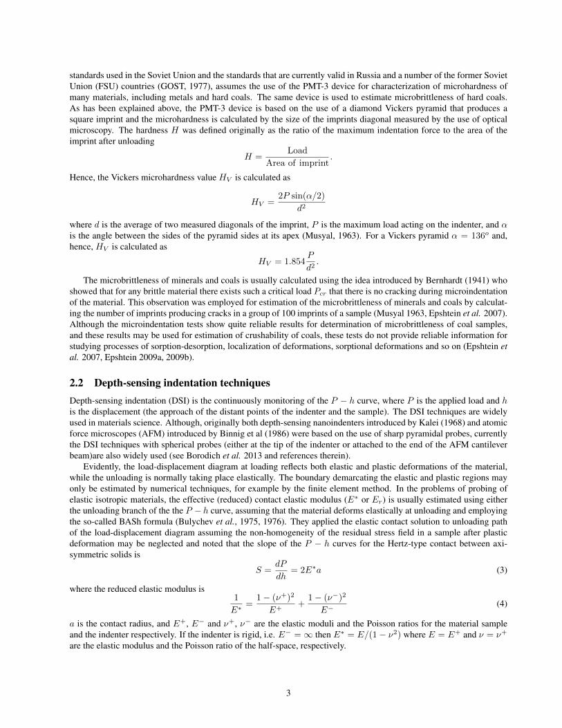
standards used in the Soviet Union and the standards that are currently valid in Russia and a number of the former SovietUnion (FSU) countries (GOST, 1977), assumes the use of the PMT-3 device for characterization of microhardness ofmany materials, including metals and hard coals. The same device is used to estimate microbrittleness of hard coals.As has been explained above, the PMT-3 device is based on the use of a diamond Vickers pyramid that produces asquare imprint and the microhardness is calculated by the size of the imprints diagonal measured by the use of opticalmicroscopy. The hardness H was defined originally as the ratio of the maximum indentation force to the area of theimprint after unloading
H =Load
Area of imprint.
Hence, the Vickers microhardness value HV is calculated as
HV =2P sin(α/2)
d2
where d is the average of two measured diagonals of the imprint, P is the maximum load acting on the indenter, and αis the angle between the sides of the pyramid sides at its apex (Musyal, 1963). For a Vickers pyramid α = 136o and,hence, HV is calculated as
HV = 1.854P
d2.
The microbrittleness of minerals and coals is usually calculated using the idea introduced by Bernhardt (1941) whoshowed that for any brittle material there exists such a critical load Pcr that there is no cracking during microindentationof the material. This observation was employed for estimation of the microbrittleness of minerals and coals by calculat-ing the number of imprints producing cracks in a group of 100 imprints of a sample (Musyal 1963, Epshtein et al. 2007).Although the microindentation tests show quite reliable results for determination of microbrittleness of coal samples,and these results may be used for estimation of crushability of coals, these tests do not provide reliable information forstudying processes of sorption-desorption, localization of deformations, sorptional deformations and so on (Epshtein etal. 2007, Epshtein 2009a, 2009b).
2.2 Depth-sensing indentation techniquesDepth-sensing indentation (DSI) is the continuously monitoring of the P − h curve, where P is the applied load and his the displacement (the approach of the distant points of the indenter and the sample). The DSI techniques are widelyused in materials science. Although, originally both depth-sensing nanoindenters introduced by Kalei (1968) and atomicforce microscopes (AFM) introduced by Binnig et al (1986) were based on the use of sharp pyramidal probes, currentlythe DSI techniques with spherical probes (either at the tip of the indenter or attached to the end of the AFM cantileverbeam)are also widely used (see Borodich et al. 2013 and references therein).
Evidently, the load-displacement diagram at loading reflects both elastic and plastic deformations of the material,while the unloading is normally taking place elastically. The boundary demarcating the elastic and plastic regions mayonly be estimated by numerical techniques, for example by the finite element method. In the problems of probing ofelastic isotropic materials, the effective (reduced) contact elastic modulus (E∗ or Er) is usually estimated using eitherthe unloading branch of the the P − h curve, assuming that the material deforms elastically at unloading and employingthe so-called BASh formula (Bulychev et al., 1975, 1976). They applied the elastic contact solution to unloading pathof the load-displacement diagram assuming the non-homogeneity of the residual stress field in a sample after plasticdeformation may be neglected and noted that the slope of the P − h curves for the Hertz-type contact between axi-symmetric solids is
S =dP
dh= 2E∗a (3)
where the reduced elastic modulus is1
E∗=
1− (ν+)2
E++
1− (ν−)2
E−(4)
a is the contact radius, and E+, E− and ν+, ν− are the elastic moduli and the Poisson ratios for the material sampleand the indenter respectively. If the indenter is rigid, i.e. E− =∞ then E∗ = E/(1− ν2) where E = E+ and ν = ν+
are the elastic modulus and the Poisson ratio of the half-space, respectively.
3

Then Bulychev et al. (1975, 1976) suggested to rewrite this exact relation (3) as
S =dP
dh=
2√A√πE∗ (5)
because the contact area A is A = πa2. Based on the examples they studied, they concluded: “an important practicalproperty of the curve of the elastic unloading of the plastic imprint is the independence of its slope at the initial stage ofthe unloading from the character of the pressure distribution under the imprint ” (Bulychev et al., 1976).
Combining (5) and (4), Bulychev et al. (1976) suggested the following expression to estimate the Young modulus oftested material
E =1− ν2
2√A/(√πS)− e2
, e2 =1− ν2indEind
. (6)
where Eind and νind are the elastic constants of the indenter.Finally, they argued that “the equations (5), (6) are applicable to both circular and square in plane shape of imprints ”
and they suggested to use (5) not only for axisymmetric punches but also for 3D indenters. In fact, (5) is a semi-empiricalapproximation for an exact expression (3).
There are also alternative approaches based on depth-sensing techniques, e.g. the BG method (Borodich and Galanov,2008, Borodich 2014) that is based on the employment of models of adhesive contact. Using the inverse analysis of astable part of an experimental loaddisplacement diagram obtained from the depth-sensing indentation of a sphere intoa sample, it may extract both the contact (reduced) modulus and the work of adhesion of the contacting pair fromone experiment. The application of the BG method to experimental curves of homogeneous materials shows that theobtained estimations of the elastic modulus and work of adhesion have very small error even for rather contaminateddata. Although the BG method is very robust to external noise and it is very fast, the method cannot be employed inits present form for extraction of mechanical characteristics of the components of such highly inhomogeneous materialsas coals. On the other hand, although the former approach for determination of E∗ based on the BASh formula hasseveral drawbacks (Borodich 2011), it is generally accepted that the results obtained for bulk material samples haveacceptable accuracy. In addition, the use of sharp nanoindenters looks very reasonable taken into account that somemicrocomponents of tested materials are very small.
Note that if the Hertz-type theory is applied to a linear elastic solid then for a general power-law shaped indenterof degree d, (the shape function f(r) = Bd(θ)r
d, Bd is the shape constant, and r, θ are the polar coordinetes) one has(Galanov, 1981, Borodich, 1983)
P ∝ hd/(d+1) (7)
Hence, if assumes that the Hertz-type solutions are applied for analysis of the unloading branch (Galanov, 1981) thenthere is a residual depth hr after unloading due to plastic deformation of the sample. Let us denote by hmax the depth atof indentation at the maximum load (Pmax). To apply the Hertz-type contact solutions, one needs to shift the origin ofthe displacement axis by hr. Thus, (7) should be written as
P ∝ (h− hr)d/(d+1). (8)
Taking a derivative of (8), one obtains an expression that is valid even for non-axisymmetric contact problems
dP
dδ∝ d
d+ 1(h− hr)−1/(d+1). (9)
Then neglecting the distortion of the surface due to plastic deformation, one obtains P ∝ (h−hr)2/3 or P = c(h−hr)2/3for a spherical indenter. Here constant c is defined as c = Pmax/(hmax − hr)2/3. For a pyramidal or conical indenter,one has P ∝ (h− hr)1/2.
Several practical approaches for evaluation of elastic modulus of material by nanoindentation were developed (see areview by Fischer-Cripps, 2011). All these approaches are based on the use of the BASh relation (5). It is clear that inorder to use (5) one needs to know the contact area. Practically it is very difficult to measure the contact area used in (5).If one considers an ideal Vickers indenter then the area of a horizontal cross-section at the height h is A(h) = 24.5h2.As it has been mentioned, the same relation is valid for an ideal Berkovich indenter. This relation was also used toapproximate the contact area by some authors. However, if the material of a sample deforms elastically then the surfaceoutside the contact region moves downwards along the z axis (like in the classic Hertz contact problem). In MaterialsScience this behaviour is called sinking-in. If the material of a sample deforms plastically then the surface outside the
4

contact region moves upwards along the z axis increasing the actual contact region. Indeed, the plastic deformationsoccur without changing the volume of the material and, therefore it goes up like an incompressible fluid during animmersion of a rigid body. The latter behaviour is called piling-up. Hence, fitting formulae for the contact area as afunction of depth at unloading were introduced. It was suggested by Oliver and Pharr (1992) to approximate the contactarea under a Berkovich indenter that may have some imperfections by the following indenter area function
A(h) = 24.5h2 +
7∑i=0
Cih1/2i (10)
where Ci are fitting parameters. Oliver and Pharr (1992) suggested also to approximate the unloading branch of thecurve as
P = α(h− hr)m (11)
where α contains geometric constants and the elastic characteristics of both the sample and the indenter, and m is apower-law exponent that is related to the geometry of the indenter: for a flat-ended cylindrical punch, m = 1; for aparaboloid of revolution, m = 1.5, and for a cone, m = 2. One can note that after shifting the coordinate origin, theexpression (11) will immediately follow from (8) and it is valid not only for axisymmetric indenters but also for non-axisymmetric indenters whose shapes are described by homogeneous functions of degree d. Hence, it follows from (8)that m in (11) can be treated as m = (d+ 1)/d. Substituting d =∞ for a flat-ended cylindrical punch, d = 1 for a coneor a pyramidal indenter and d = 2 for a paraboloid, one obtains the corresponding values of m in the approximation(11). Thus, the approximation (11) may be explained as consisting of the shift of the coordinate origin of the P − hcurve and the assumption that the indenter shape is described by a power-law function Bd(θ)rd of degree d.
2.3 Specific features of indentation tests of the inhomogeneous materialsLet us consider coals as an example of a natural inhomogeneous material. The heterogeneity of coals exists at manylength scales from the nano to the macroscale. It defines specific features of the physical and mechanical propertiesof coals. Coals are composed of a number of distinct organic entities called macerals and some amount of inorganicsubstances along with internal pores and cracks. The organic part of coals contains from 65 to 95 % carbon dependingon the degree of the coal metamorphism. The maceral composition of coals is defined by many factors such as specificfeatures of the coalification processes, the nature of the initial plant material and the conditions of its accumulation anddecomposition. It is customary to identify three basic groups of coal macerals: vitrinite, inertinite and liptinite. In eachof these groups it is also possible to allocate different submacerals. The vitrinite group macerals are glass-like materialswhere the original cellular plant structure has practically disappeared, while the liptinite macerals retain this structure.In other words, the microstructure of the liptinite group macerals includes the transformed remains of plants that includebiochemically stable fragments of plant spores, cuticles, resins and suberin biopolymers. The inertinite group can bedefined as fossilized charcoal.
It is not simple to separate coals into pure macerals. Indeed, coals are highly heterogeneous materials and the sizeof a specific maceral in a coal specimen is often smaller than the size of the imprint of the microhardness tester. Hence,microhardness tests usually show results not for a pure maceral but for a mixture of macerals, and there is normally aconsiderable scatter of the data obtained for the same sample. As a result, just the nominal hardness values of a testedcoal sample obtained by averaging of 10-30 measurements, could be calculated. An extended review of the applicationof microindentation for evaluation of microhardness and microbrittleness of coals was given by Musyal (1963). It wasfound the following values for microhardness (H) of coals: (i) H = 60− 200N/mm2 for brown and low volatile coals;(ii) H = 250 − 350N/mm2 for high volatile coals; (iii) H = 430 − 1400N/mm2 for anthracites (Musyal 1963,Epshtein et al. 2007). Later results of microhardness studies were published by many researchers (see, e.g. Hower et al.2008, Epshtein 2009, Kozusnıkova, 2009, and references therein).
There are problems related to the use of the microindentation tests. The customarily used techniques of microinden-tation allow the researcher to characterize the relatively large components of materials (usually the characteristic sizeof the component region has to be over 40 µm) while micromechanical properties have to be assessed separately forits individual constituents at microscale. Although it is possible to evaluate microhardness of macerals of the vitrinitegroup in a reliable way, the microhardness indenters can barely be used to evaluate the microhardness of macerals of theinertinite group and they cannot be used for measurements of the properties of macerals of the liptinite group due to thesmall size of these maceral inclusions. Further, the microindentation tests do not normally record the load-displacementcurve but rather they are based on the use of the plastic imprint in the sample. Hence if the maximum load was very
5

low then sometimes it is practically impossible to see the imprint due to low level of plastic deformations. On the otherhand, if Pmax greater than Pcr then there are some cracks in the sample. In addition, the elastic modulus of a testedmaterial can be estimated using the BASh relation or its extensions that, in turn is based on the employment of the DSItechniques. One cannot extract the elastic modulus using traditional microindentation techniques. Hence, we believethat the employment of the modern DSI techniques is more preferable than the traditional microindentation techniques.
One of problems that contribute to the difficulty in application of indentation techniques to natural inhomogeneousmaterials is presence of numerous initial microcracks and voids. Microindentation tests of relatively thick coal samplesare often influenced by the pores and cracks within the sample. Since coal samples prepared for microhardness testingare normally relatively thick, it was not possible to employ either transmission electronic microscopy (TEM) or atomicforce microscopy (AFM) to enable detailed phase and crack distribution analysis. In addition, microindentation tests ofrelatively thick coal samples can produce imprints of quite distinctive appearance of inverse stepped pyramids that looklike American pyramids or the pyramid of Djoser rather than the other more famous Egyptian pyramids. It is arguedthat to avoid the influence of the pores and cracks, the samples of the materials have to be prepared as very thin and verysmooth sections. Note if the material has layered structure then the sample has to be prepared as a cross-section of thelayers.
Evidently, indentation techniques have to be accompanied by the use of microscopy techniques. Both reflected lightand transmitted light techniques may be employed. Vitrinite varies from light brown to red colour in transmitted lightand it appears as pale grey in reflected light. The colours of the microcomponents of the inertinite group in reflectedlight microscopy vary from yellow to white and they appear black in transmitted light. As a rule, there are rather sharpboundaries that separate macerals or submacerals. However, if one lookes at a thin section of a coal sample in thereflected light then it is not very simple to recognize the distinct macerals. Indeed, the inertinite group macerals haveblack colour, and the vitrinite group macerals looks pale grey and the liptinite group macerals looks grey (Fig. 1). On theother hand, the boundaries between macerals can be clearly seen by examination of thin sections of coals in transmittedpolarised light. The micro and nanoscale pores can be also clearly seen in the sample (Figure 2). We have to emphasizethat the transmitted light techniques may be employed only for thin sections of the materials.
For the first tests of coal thin sections, coals of the Donetsk and Kizel (Ural region) coal basins were chosen. Bothtypes of coals consist of about 85-90% of vitrinite, while the rest is presented by other marcerals and a small amountof inorganic substances. To prepare coal samples of 25 × 25 mm, they were glued to glass bases. The thickness ofthe glue layer was 12-15 µm. Using a RotoPol (Struers) polishing machine, the 13-14 µm thick sections of coals wereprepared at Laboratory of Physics and Chemistry of Coals, NUST MISiS. The sample surfaces were perpendicular tothe coal layered structure. Typical transmitted light micrographs of the two types of coal are shown in Figures 2 and 3.For reliable measurement of the properties of individual macerals, it is assumed that the structures are the same throughthe thickness of the section. However, local tilting of the layered structure may occur and this might affect the reliabilityof the indentation data.
Because the samples were very thin we were able to locate the indentations in clearly visible regions occupiedby a specific maceral. The prepared samples were very smooth and allowed us to use the automated depth-sensingnanoindentation techniques available at Newcastle University in regions occupied by specific marcerals. The transmittedlight microscopy was used to identify the co-ordinates of specific macerals to test and these were located by a motorisedstage and confirmed by reflected light microscopy in the nanoindentation system. Nanomechanical testing using aHysitron TriboIndenter (Hysitron Inc., Minneapolis, MN) was performed at room temperature using a well-used three-sided pyramidal shaped Berkovich diamond indenter with a tip end radius of 250nm
Determination of mechanical properties of individual macerals was performed within a chosen 100 × 100 micronregion. This enabled the consistency of the data to be checked and systematic errors due to maceral alignment andedge proximity to be assessed. The maximum load of all nanoindentation tests were 10 mN . The spacing betweenindents was 10 µm in a 10× 10 array. With the large number of indentation test results at each location it was possibleto generate local maps of mechanical properties to identify trends in the data which reveal edge effects and give astatistically meaningful characterization of the tested region. Initially the tests were done under open loop control usinga triangular load function. However, in some experiments creep or viscoelasticity was observed even before the peakload of 1mN was reached. The tests were then repeated using two different loading protocols: a trapezoidal load schemewith 2 s hold at 1 mN maximum load and a displacement control experiment to 400 nm maximum depth with 2 s holdat maximum depth. These experimental schemes as functions of time (a trapezoidal load function and the displacementcontrol scheme) were used to assess the extent to which creep run-out occurs. For each indent, the contact modulus wascalculated using the common Oliver-Pharr method.
6
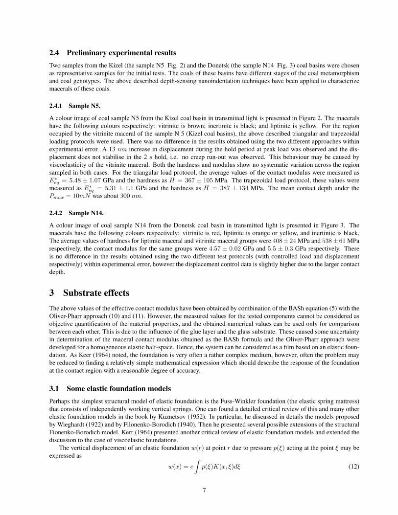
2.4 Preliminary experimental resultsTwo samples from the Kizel (the sample N5 Fig. 2) and the Donetsk (the sample N14 Fig. 3) coal basins were chosenas representative samples for the initial tests. The coals of these basins have different stages of the coal metamorphismand coal genotypes. The above described depth-sensing nanoindentation techniques have been applied to characterizemacerals of these coals.
2.4.1 Sample N5.
A colour image of coal sample N5 from the Kizel coal basin in transmitted light is presented in Figure 2. The maceralshave the following colours respectively: vitrinite is brown; inertinite is black; and liptinite is yellow. For the regionoccupied by the vitrinite maceral of the sample N 5 (Kizel coal basins), the above described triangular and trapezoidalloading protocols were used. There was no difference in the results obtained using the two different approaches withinexperimental error. A 13 nm increase in displacement during the hold period at peak load was observed and the dis-placement does not stabilise in the 2 s hold, i.e. no creep run-out was observed. This behaviour may be caused byviscoelasticity of the vitrinite maceral. Both the hardness and modulus show no systematic variation across the regionsampled in both cases. For the triangular load protocol, the average values of the contact modulus were measured asE∗eq = 5.48 ± 1.07 GPa and the hardness as H = 367 ± 105 MPa. The trapezoidal load protocol, these values weremeasured as E∗eq = 5.31 ± 1.1 GPa and the hardness as H = 387 ± 134 MPa. The mean contact depth under thePmax = 10mN was about 300 nm.
2.4.2 Sample N14.
A colour image of coal sample N14 from the Donetsk coal basin in transmitted light is presented in Figure 3. Themacerals have the following colours respectively: vitrinite is red, liptinite is orange or yellow, and inertinite is black.The average values of hardness for liptinite maceral and vitrinite maceral groups were 408± 24 MPa and 538± 61 MParespectively, the contact modulus for the same groups were 4.57 ± 0.02 GPa and 5.5 ± 0.3 GPa respectively. Thereis no difference in the results obtained using the two different test protocols (with controlled load and displacementrespectively) within experimental error, however the displacement control data is slightly higher due to the larger contactdepth.
3 Substrate effectsThe above values of the effective contact modulus have been obtained by combination of the BASh equation (5) with theOliver-Pharr approach (10) and (11). However, the measured values for the tested components cannot be considered asobjective quantification of the material properties, and the obtained numerical values can be used only for comparisonbetween each other. This is due to the influence of the glue layer and the glass substrate. These caused some uncertaintyin determination of the maceral contact modulus obtained as the BASh formula and the Oliver-Pharr approach weredeveloped for a homogeneous elastic half-space. Hence, the system can be considered as a film based on an elastic foun-dation. As Keer (1964) noted, the foundation is very often a rather complex medium, however, often the problem maybe reduced to finding a relatively simple mathematical expression which should describe the response of the foundationat the contact region with a reasonable degree of accuracy.
3.1 Some elastic foundation modelsPerhaps the simplest structural model of elastic foundation is the Fuss-Winkler foundation (the elastic spring mattress)that consists of independently working vertical springs. One can found a detailed critical review of this and many otherelastic foundation models in the book by Kuznetsov (1952). In particular, he discussed in details the models proposedby Wieghardt (1922) and by Filonenko-Borodich (1940). Then he presented several possible extensions of the structuralFionenko-Borodich model. Kerr (1964) presented another critical review of elastic foundation models and extended thediscussion to the case of viscoelastic foundations.
The vertical displacement of an elastic foundation w(r) at point r due to pressure p(ξ) acting at the point ξ may beexpressed as
w(x) = c
∫p(ξ)K(x, ξ)dξ (12)
7

where c is a constant that depends on the elastic properties of the foundation, and K the kernel of the integral equation(Kuznetsov, 1952). Wieghardt (1922) suggested to describe the kernel as an exponential function
K(x, ξ) = e−b|x−ξ| (13)
where b is a constant depending on the the elastic foundation because 1/b represents the characteristic length of actionof the elastic foundation. The idea of an exponentially decaying action of the elastic foundation may be used to describethe equivalent composite modulus by the relation (1).
Comments.1. As it was noted by Kuznetsov (1952), Wieghardt did not suggested any structure for his model of an elastic
foundation as did Fuss or Winkler. In fact, N. Fuss considered an elastic beam floating on the surface of an ideal liquid;using the beam theory of his teacher L. Euler he wrote an equation for a beam on elastic foundation. Almost a centurylater, E. Winkler suggested to model an elastic foundation as mattress consisting of non-connected elastic springs with thespring constant k. To achieve some degree of interaction between the spring elements, it was proposed by Filonenko-Borodich (1940) to connect the top ends of the springs of the Fuss-Winkler foundation by a stretched elastic string(or membrane) subjected to a constant-tension field T . The interaction of the spring elements is characterized by theintensity of the tension field T in the string. Denoting ω2 = k/T , it is easy to find (see, e.g. Kuznetsov, 1952) that theFilonenko-Borodich structural model loaded by a concentrated load at the coordinate origin leads to
w(x) = e−ωx/(2Tω)
and this in turn leads to (12) with (13) where
c = (2Tω)−1, b = ω.
2. The same equation (12) with an exponentially decaying kernel (13) can be derived using other elastic foundationmodels, e.g. the two-parameter Pasternak model and the Vlasov-Leontiev model (see, e.g. Kuznetsov, 1952, Kerr, 1964).However, one of the authors (FB) believes that the use of the Filonenko-Borodich model (1940) is more appropriate formany problems of nanomechanics to describe contact interactions between very soft materials whose behaviour is largelyaffected by the surface tension. However, this discussion is out the scope of the present paper.
3.2 The approximative approachesSome approximations for the relation (1) were discussed in many papers including papers by Mencık et al. (1997), Bull(2004), and Argatov & Sabina (2013). In particular it was suggested to represent Φ as a linear function, i.e.
Ψ(x) = x, x = h/t (14)
where t is the thickness of the film (the material section).Another approach is based on the use an exponential function, i.e.
Φ1(x) = e−αx (15)
and respectivelyE∗eq = E∗s + (E∗f − E∗s )e−αx (16)
These are many other approaches based on the relations (1) and (2) that we will not discuss here.One can see in Figure 4 the values of the equivalent reduced (contact) modulus E∗eq for varying contact depths
(the maximum indentation depth) calculated for tests on the above mentioned sample N5. The red points correspondto vitrinite maceral, while the blue points correspond to inertinite maceral. Because the thin section was glued to thesubstrate and the glue thickness was 14 µm that was equal to the thickness of the section t, we need to use (1) takinginto account E∗s = 2GPa. As the first approximation, the sample/elastic foundation system has been described usingthe exponential weight function (16). Solving the inverse problem, one can find the values of α and E∗f . In particular itwas found that (see Figure 5)
E∗eq = 2 + 19e−30x
for vitrinite (red line)E∗eq = 2 + 25e−30x
8

for inertinite (blue line). For the first sight, it looks strange that Ef = 21GPa for vitrinite and Ef = 27GPa forinertinite, while one can see in Figure 2 that E∗eq = 3.2± 0.1GPa for vitrinite and E∗eq = 5.0± 0.4GPa for inertinite.However, if one takes into account that these values were obtained for tests with hmax ≈ 300µm then it is possible tosee that Figure 2 and Figure 4 are in full agreement with each other. Comparing the detailed graphs (see Figure 6) ofthe relation (16) for the equivalent modulus with the exponentially decaying weight function (t = 14µm, ES = 2GPa,α = 30, E∗f = 21GPa and E∗f = 21GPa for vitrinite and inertinite macerals respectively) and Figure 4), one canfind that these values are in good agreement with the experimental data for a three-sided pyramidal shaped Berkovichdiamond indenter.
4 ConclusionsIt is known that it is possible to predict the behaviour of a heterogeneous material at meso and macroscales using the
methods of micromechanics of materials (Nemat-Nasser and Hori 1999). However, despite the importance of knowledgeabout micromechanical properties of compounds, the information about the material properties of these componentsis often absent. Taking coals as an example of such an inhomogeneous materials, the experimental and numericaltechniques for evaluation of mechanical properties of highly inhomogeneous materials are discussed.
It has been argued that the DSI techniques have to be employed for testing material samples rather than the con-ventional microindentation. The main difference between the common microindentation and the modern depth-sensingindentation techniques is that the former uses just one measurement of the plastic imprint of the sample, while the lat-ter extracts information from the continuous diagrams obtained during loading and unloading of the indenter. Hence,depth-sensing nanoindentation can be applied to much smaller objects than used for microindentation tests. In addition,the modern techniques allow researchers to extract much more information about the mechanical behaviour of the testedmaterial, in particular to extract the contact modulus of the contacting pair.
It has been explained why the samples of the materials have to be prepared as very thin and very smooth sections.Indeed, the use of such sections alow us to avoid the influence of the pores and cracks. In addition, transmitted lightmicroscopy can be used, that in turn allows us to visualise the tested regions. With the large number of indentationtest results at each location it was possible to generate local maps of mechanical properties to identify trends in thedata which reveal edge effects and give a statistically meaningful characterisation of the tested region. For example,mechanical properties of individual macerals have been determined within chosen 100x100 micron regions. This enabledthe consistency of the data to be checked and systematic errors due to maceral alignment and edge proximity to beassessed.
It has been demonstrated that the use of the modern nanoindentation techniques integrated with transmitted lightmicroscopy is very effective for evaluation of elastic modulus of coal macerals. However, because the thin sections areglued to the substrate, the approximative approaches have to be used to extract the real elastic modulus of the testedmaterial from the information about the relation of the equivalent modulus calculated for varying contact depth. Theproposed approach is demonstrated on application to the experimental data obtained by Berkovich nanoindentation
AcknowledgmentsThe work was partly supported by a grant from the Ministry of Education and Science of the Russian Federation in
the framework of Increase Competitiveness Program of NUST MISiS (NoK3-2014-062)
9

References[1] Argatov, I.I., & Sabina, F.J. (2013). Asymptotic analysis of the substrate effect for an arbitrary indenter. Quarterly
Journal of Mechanics and Applied Mathematics, 66, 75-95.[2] Argatov, I.L. and Sabina, F.J. (2014) Small-scale indentation of an elastic coated half-space: Influence of Poisson’s
ratios on the substrate effect. Int. J. Eng. Sci., 8, 33–40.[3] Ban, H., Karki, P., and Kim, Y. (2014) Nanoindentation test integrated with numerical simulation to characterize
mechanical properties of rock materials. J. Testing and Evaluation, 42, 787–796.[4] Bernhardt, E.O. (1941) Uber die Mikroharte der Feststoffe im Grenzbereich des Kickschen Ahnlichkeitssatzes.
Zeitschrift fur Metallkunde. 33, 135–139.[5] Binnig, G., Quate, C.F. and Gerber, C. (1986) Atomic force microscope. Phys. Rev. Lett., 56, 930–933 .[6] Borodich, F.M. (1983) Similarity in the problem of contact between elastic bodies. PMM J. Appl. Math. Mech., 47,
519–521.[7] Borodich, F.M. (2011) Contact problems at nano/microscale and depth sensing indentation techniques. Materials
Science Forum, 662, 53–76.[8] Borodich, F.M. (2014) The Hertz-type and adhesive contact problems for depth-sensing indentation. Advances in
Applied Mechanics, 47, 225–366.[9] Borodich, F.M. and Galanov, B.A. (2008) Non-direct estimations of adhesive and elastic properties of materials by
depth-sensing indentation. Proc. R. Soc. Lond. A,, 464, 2759–2776.[10] Borodich, F.M., Galanov, B.A., Gorb, S.N., Prostov, M.Y., Prostov, Yu.I. and Suarez-Alvarez, M.M. (2013) Evalu-
ation of adhesive and elastic properties of polymers by the BG Method. Macromolecular Reaction Engineering, 7,555–563.
[11] Borodich, F.M. and Keer, L.M. (2004) Contact problems and depth-sensing nanoindentation for frictionless andfrictional boundary conditions. Int. J. Solids Struct., 41, 2479–2499.
[12] Bull, S.J. (2005) Nanoindentation of coatings. J. Phys. D: Appl. Phys., 38, R393-R413.[13] Bulychev, S.I., Alekhin, V.P., Shorshorov, M.Kh., Ternovskii, A.P. and Shnyrev, G.D. (1975) Determination of
Youngs modulus according to indentation diagram. Industrial Lab., 41, 1409-1412.[14] Chaudhri, M.M. and Lim Y.Y. (2007) Nanoindentation techniques: A critical assessment of the current methods of
data analysis. Key Engineering Materials, 345 - 346, 1107–1114.[15] Chen, J. and Bull, S.J. (2009) Modeling of indentation damage in single and multilayer coatings. In: IUTAM
Symposium on Modelling Nanomaterials and Nanosystems, Vol. 13, Pyrz, R. and Rauhe, J.C.M. (Eds.), 161-170.[16] Constantinides, G. and Ulm, F.-J. (2004) The effect of two types of CSH on the elasticity of cement-based materials:
Results from nanoindentation and micromechanical modeling. Concr Res, 34, 67-80.[17] Constantinides, G., Ulm, F.-J. and Van Vliet, K. (2003) On the use of nanoindentation for cementitious materials.
Mat Struct., 36, 191-196.[18] Eremin, I.A., Lebedev, V.V. and Tsikarev, D.A. (1980) Petrography and Physical Properties of Coals. Moscow,
Nedra (Russian)[19] Epshtein, S.A. (2009) Physical and mechanical properties of the coal vitrinites of the different genotypes. Mining
Informational and Analytical Bulletin, # 8, 58–69. (Russian)[20] Epshtein, S.A. (2009) Crack formation in the coals of the different genotypes. Mining Informational and Analytical
Bulletin, # 9, 71–76. (Russian)[21] Epshtein, S.A. Barabanova, O.V., Minaev, V.I., Weber, J. and Shirochin, D.L. (2007) Effect of dimethylformamide
treatment of coals on their thermal degradation and elastic-plastic properties. Solid Fuel Chemistry, 41, 210–215.[22] Epshtein, S.A. Borodich, F.M. and Bull, S.J. (2014) Nanoindentation techniques for determination of mechanical
properties of coal macerals. (submitted).[23] Filonenko-Borodich, M.M. (1940) Some approximate theories of the elastic foundation. Uchenye Zapiski
Moskovskogo Gosudarstvennogo Universiteta. Mekhanika, No. 46, 3–18. (Russian)[24] Fischer-Cripps, A.C. (2011) Nanoindentation. Springer.[25] Galanov, B.A. (1981) Approximate solution of some contact problems with an unknown contact area under condi-
tions of power law of material hardening. Dopovidy Akademii Nauk Ukrainskoi RSR, Ser. A, No. 6, 35–40. (Russianand Ukrainian)
[26] Gao, H., Chiu, C.-H., and Lee, J. (1992) Elastic contact versus indentation modeling of multi-layered materials.International Journal of Solids and Structures, 29, 2471-2492.
10

[27] GOST 21206-75 (1977) Hard coals and anthracite. Determination method for microhardness and microbrittleness.(Russian)
[28] Hower, J., Trinkle, E.J., Raione, R.P. (2008) Vickers microhardness of telovitrinite and pseidovitrinite from highnolatile bituminous Kentucky coals. Int. J. Coal Geology, 75, 76–80.
[29] Hughes, J.J., Trtik, P. (2004) Micro-mechanical properties of cement paste measured by depth-sensing nanoinden-tation: a preliminary correlation of physical properties with phase type. Materials Characterization, 53, 223-231.
[30] Iofis, M.A. and Shmelev, A.I. (1985) Engineering Geomechanics at Underground Developments. Moscow, Nedra.(Russian)
[31] Jung, Y.G., Lawn, B.R., Martyniuk, M., Huang, H. and Hua, X.Z. Evaluation of elastic modulus and hardness ofthin films by nanoindentation. J. Mater. Res., 19, 3076-3080.
[32] Kalei, G.N. (1968) Some results of microhardness test using the depth of impression. Mashinovedenie 4(3), 105–107 (Russian).
[33] Kerr, A.D. (1964) Elastic and viscoelastic foundation models, J. Appl. Mech., 31, 491-498[34] Kozusnıkova, A. (2009) Determination of microhardness and elastic modulus of coal components by using inden-
tation method. GeoLines, 22, 40–43.[35] Khrushchov, M.M. and Berkovich, E.S. (1950) Devices PMT-2 and PMT-3 for microhardness testing. Moscow-
Leningrad, USSR Academy of Sciences Publisher. (Russian)[36] Khrushchov, M.M. and Berkovich, E.S. (1951) Methods of determining the hardness of very hard materials: the
hardness of diamond. Industrial Diamond Review, 11, 42-49.[37] Kuznetsov, V.I. (1952) Elastic Foundation, Moscow, GosIzdLitStrArkh. (Russian)[38] Mencık, J., Munz, D., Quandt, E., Weppelmann, E.R. and Swain, M.V. (1997) Determination of elastic modulus of
thin layers using nanoindentation. J. of Materials Research, 12, 2475–2484.[39] Meyers, R. (Ed.) (1982) Coal Structure. Academic Press.[40] Miller, B.G. (2010) Clean Coal Engineering Technology, Butterworth-Heinemann, Oxford.[41] Musyal, S.A. (1963) Microhardness and microbrittleness as possible parameters for classification of fossil coals.
In: Petrographic Specific and Properties of Coals. Ed. Ammosov, I.I., Ch. 3, 164–188, Moscow, USSR Academyof Sciences Publisher. (Russian)
[42] Nemat-Nasser, S. and Hori, M. (1994) Micromechanics: Overall Properties of Heterogeneous Materials, North-Holland.
[43] Nemecek, J. (2009) Creep effects in nanoindentation of hydrated phases of cement pastes. Materials Characteri-zation, 60, 1028-1034.
[44] Smith, R.L. and Sandland, G.E. (1925) Some notes on the use of a diamond pyramid for hardness testing. J. Ironand Steel Inst., 111, 285–294.
[45] Oliver, W.C. and Pharr, G.M. (1992) An improved technique for determining hardness and elastic modulus usingload and displacement sensing indentation experiments. J. Mater. Res., 7, 1564-1583.
[46] Velez K, Maximilien S, Damidot D, Fantozzi G, Sorrentino F. (2001) Determination by nanoindentation of elasticmodulus and hardness of pure constituents of Portland cement clinker. Cem Concr Res., 31, 555-561.
[47] Wang, G.X., Wang, Z.T., Rudolph, V., Massarotto, P. and Finley, R.J. (2007) An analytical model of the mechanicalproperties of bulk coal under confined stress. Fuel, 86, 1873–1884.
[48] Wieghardt, K. (1922) Uber den Balken auf nachgiebiger Unterlage. Zeitsehrift fur angewandte Mathematik undMechanik, 2, 165-184.
[49] Zhu, W. and Bartos, P.J.M. (1997) Assessment of interfacial microstructure and bond properties in aged GRC usinga novel micro indentation method. Cem. Concr. Res. 27, 1701-1711.
[50] Zhu, W. and Bartos, P.J.M. (2000) Application of depth-sensing microindentation testing to study of interfacialtransition zone in reinforced concrete. Cem. Concr. Res. 30, 1299-1304.
[51] Zhu, W., Hughes, J.J., Bicanic, N., and Pearce, C.J. (2007) Nanoindentation mapping of mechanical properties ofcement paste and natural rocks. Materials Characterization, 58, 1189-1198.
11

Figure 1: A thin section of a coal sample in reflected light. Macerals of the inertinite, vitrinite and liptinite groups haveblack, pale grey and grey colours respectively. The micro and nanoscale pores are also present in the sample.
Figure 2: A colour image of coal sample N5 (Kizel coal basin) in transmitted light (vitrinite has brown coulour; inertiniteis black; and liptinite is yellow). The relatively uniform vitrinite (brown) regions are relatively soft and viscoelastic butthe inertinite (mottled brown) areas are stiffer and show no viscoelasticity.
12

Figure 3: A colour image of coal sample N14 (Donetsk coal basin) in transmitted light (vitrinite has red colour; liptiniteis orange; and inertinite is black). The maximum load of all nanoindentation tests was 10 mN.
Figure 4: Reduced (contact) modulus depth of indentation experimental relation for sample N5 (Kizel coal basin).Comparison between vitrinite (red points) and inertinite (blue points) macerals.
13

Figure 5: Reduced (contact) modulus depth of indentation. Comparison between vitrinite (red line) and inertinite (blueline) macerals.
14

Figure 6: A detailedEeq−h graphs for vitrinite (red line andEf = 21GPa) and inertinite (blue line andEf = 27GPa)macerals. The exponential relation (16) is used with t = 14µm, ES = 2GPa and α = 30.
15


![Enhancement of Elastic Modulus of Epoxy Resin with Carbon ... · k modulus to force micros properties of ... ll carbon nan hardness; R ian et al [5] c ... where E and µ are Young’s](https://img.dokumen.tips/doc/110x75/5ca8dc6888c99371398b9061/enhancement-of-elastic-modulus-of-epoxy-resin-with-carbon-k-modulus-to-force.jpg)