Embed Size (px)
Citation preview

Evaluating the Centralization of Vacuum Systems
For your free subscription, please visit http://www.blowervacuumbestpractices.com/magazine/subscription.
Tim Dugan P.E., Compression Engineering CorporationFeatured Speaker
Sponsored by

Handouts
Engineering Services 2017
▪ Energy analysis services:
For industrial compressed air, process vacuum, pneumatic
conveying, process pumping, industrial process cooling and other
similar electric motor-driven rotating machinery systems:
o Walk-through and development of potential opportunities and
solutions
o Energy efficiency measure selection
o Data-logging
o Data-reduction
o Analysis and simulation
o Project budgeting
o Report writing
o Peer review
o Commissioning
o Inspection
o Re-tuning/re-commissioning
o Energy management
▪ Project technical services:
o Control system specification
o P&ID development
o Equipment layout and piping design
o Ventilation design
o Submittal review
o Commissioning
▪ Miscellaneous services:
o Performance testing
o Tuning and re-tuning
o Leak assessments
o Remote monitoring of key performance indicators
o Project management
o System start-up assistance and trouble-shooting
o Standards and procedures development
o Training
All rights are reserved. The contents of this publication may not be reproduced in whole or in part without consent of Smith Onandia Communications LLC. Smith
Onandia Communications LLC does not assume and hereby disclaims any liability to any person for any loss or damage caused by errors or omissions in the material contained herein, regardless of whether such errors result from
negligence, accident, or any other cause whatsoever.
All materials presented are educational. Each system is unique and must be evaluated on its own merits.

Introduction by Rod Smith, Publisher
Blower & Vacuum Best Practices Magazine
Evaluating the Centralization of Vacuum Systems
For your free subscription, please visit http://www.blowervacuumbestpractices.com/magazine/subscription.

Tim Dugan P.E.,Compression Engineering Corporation
• President and Principal Engineer of Compression Engineering Corporation
• Over 25 years of experience in the industry
About the Speaker
For your free subscription, please visit http://www.blowervacuumbestpractices.com/magazine/subscription.
Sponsored by

Centalized Vacuum
Systems
Tim DuganCompression Engineering Corp.
Blower & Vacuum Best Practices Magazine
6-29-17
Presentation is property of Smith OnandiaCommunications
Do not copy or distribute without permission

Outline
• Fundamentals of Vacuum
• Problem Description – Multiple Dead-headed Processes
• Solution 1: Consolidation
• Solution 2: Centralization

Fundamentals of
Vacuum
• Mass Flow vs Volume Flow
• System Curve & Choked Flow
• Typical PD Vacuum Pump
• Typical PD Vacuum Pump Curve

Fundamentals: Mass
Flow vs. Volume Flow
• Volume flow, in “icfm” or “m3/hr”, is always
at the vacuum pump inlet, and is not
density-weighted. Pure volume / time.
• Mass / volume flow = (Patm – Pin) / Patm
• Example: at 25”Hg vac and sea level,
icfm/scfm = (29.92 - 25)/29.92 = 0.164

Fundamentals: Mass
Flow vs. Volume Flow
• That means that you only get 16.4% of the flow
at the outlet of the vacuum pump as you do the
inlet, or that the process “sees” just 16.4% of the
ambient air come in, and it gets “stretched” 6X
by the time it comes into the vacuum pump.
• Since vacuum pump size and cost is determined
by the inlet volume, this is a critical economic
issue.
• For instance, designing for 27.5”Hg drops
icfm/scfm to 8.3%, doubling the size requirement
vs. 25”Hg!

System Curve
• Flow across a resistance is proportional to the
square root of the vacuum level. The
relationship between flow is the “system curve”.
• There is a maximum flow, however.

Choked Flow
• At about 14”Hg, your system (essentially a hole)
reaches sonic velocity, and mass flow is
“choked”.

Choked Flow
• Based on the
icfm/scfm ratio, you
can pull infinite inlet
“flow”, but not get any
more mass flow.
• You might think your
system can win the
World Series, but it
will CHOKE!
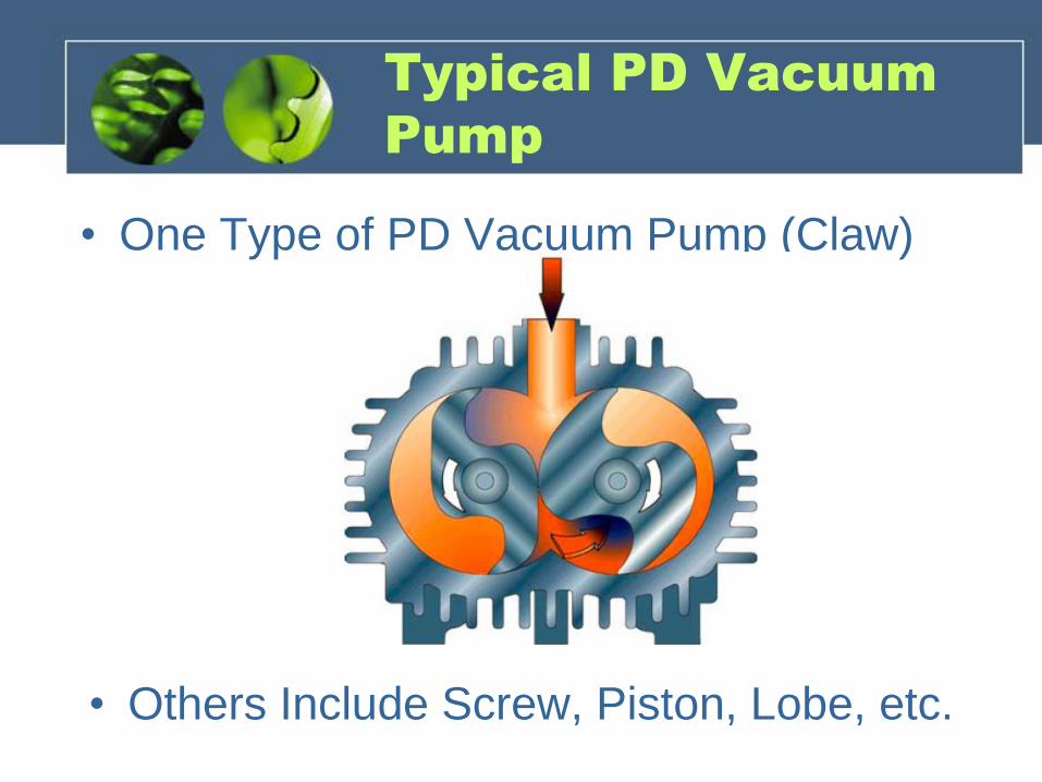
Typical PD Vacuum
Pump
• One Type of PD Vacuum Pump (Claw)
• Others Include Screw, Piston, Lobe, etc.

Typical Vacuum
Pump System
• Dry PD vacuum pumps
are simple: vacuum
pump, motor, and
controls.
• Lubricated vacuum
pumps include oil-
separator and lube
system.
• Deep vacuum systems
can have two vacuum
pumps in series.

Typical Vacuum
Pump System
• Vacuum pump skids
can be consolidated
in systems with
piping and master
controls.

Problem Description
• Four cabinet door routing tables with 4’x8’ capacity.
• Table is a “variable orifice”, and vacuum pump pulls
from atmosphere, through table, to pump inlet.
• More production = more coverage. Less production =
less coverage.
• Dedicated 40hp vacuum pumps, several makes, all
lubricated.
• Max power is at min production.
• Very little “turn-down” as production (coverage) goes
up.

Problem Description
• Full routing table:
• Empty routing table:

Problem Description

Problem Description
• Assess
System: Vac
& kW was
data-logged.
Often dead-
headed.
• Often enough
to justify a
project (about
60 kW
average
savings).

Problem Description
• That’s like having to build a house for the whole
baseball team to drop in at any time, or just you and
your spouse. It might be a bit oversized!

Problem Description
• Worse than that!
• You have many machine centers. You have a “Street
of Dreams”, with most of the houses empty!

Solution 1:
Consolidation
• Design Consolidation (engineering needed):
– Piping: Looped, large enough for max flow of all 4
tables
– VSD on at least one vacuum pump recommended
– Storage: Sufficient for controls (depends on pump
size, VSD, etc)
– Master controls. If a VSD, keep in “trim” all the time,
“target” algorithm.
– Consider adding back-up vacuum pump or new VSD
vacuum pump.

Solution 1:
Consolidation

Solution 1:
Consolidation
• Pros:
– Uses existing vacuum pumps
– Less installation cost
• Cons:
– Tank size and location
– More complex project. Requires some engineering
and integration

Solution 2:
Centralization
• Design centralization (engineering needed):
– Site engineering:
• Looped piping, large enough for max flow of all 4 tables
• Electrical/mechanical installation of multiplex skid.
– Size mulitplex vacuum pump skid for max flow of all
tables, with single redundancy.
– Have vendor propose several alternatives, VSD and
not. Might need more smaller vacuum pumps for no
VSD, and larger receiver.
– Master controls, factory-wired, programmed, and
tested.

Solution 2:
Consolidation
• Pros:
– Less site engineering and installation time.
– Lower electrical & integration cost.
– Potentially higher efficiency vacuum pumps.
• Cons:
– More space – for skid.
– Possibly higher initial cost (trade-off of equipment vs.
installation).

Summary
• Vacuum Fundamentals
– Your system is inherently “choked”, so don’t oversize.
– Deeper vacuum than needed creates large vac pumps.
• Problem Description
– Multiple systems with max to dead-head flow
– Vacuum pumps run at max power at no production
• Consolidation Option:
– Use existing vac pumps; add piping, storage, & controls
• Centralization Option:
– Add piping; install new multiplex vacuum skid with
storage & controls from factory

Greg MarciniakAtlas Copco Compressors
• Product Marketing Manager for the Industrial Vacuum Division of Atlas Copco Compressors
About the Speaker
For your free subscription, please visit http://www.blowervacuumbestpractices.com/magazine/subscription.

CENTRALIZED VSDVACUUM SYSTEMS
Greg Marciniak
Product Marketing
Manager – Atlas Copco

TRADITIONAL FIXED SPEED CONTROLS
32

TRADITIONAL FIXED SPEED CONTROLS
33
Atmosphere
Perfect Vacuum
Cut In
Cut Out
OPERATING
RANGE
Vacuum Transducer
Vacuum Switch
22”HgV
26”HgV
0”HgV
29.92”HgV

OPTIMIZING PRESSURE - BOYLE’S LAW
34
P1V1 = P2V2
…designing for 27.5”Hg requires twice the size vacuum pump as 25”Hg

OPTIMIZING PRESSURE - BOYLE’S LAW
35
P1V1 = P2V2

36
OPTIMIZING PRESSURE - BOYLE’S LAW
P1V1 = K

37
Imagine a process demand of:
• 27.5”HgV (29.92 - 27.5 = 2.42”HgA)
• 300 acfm
P = 2.42”HgA (always use absolute terms)
V = 300 acfm
PV = (2.42)(300) = K = 726 (constant)
What does it all mean for the end customer?
OPTIMIZING PRESSURE - BOYLE’S LAW

38
So, if we can adjust the vacuum level to
25”HgV (29.92 – 25 = 4.92”HgA)
P = 4.92”HgV (always use absolute terms)
K = 24,600 (from previous calculation)
V = ? acfm
PV = (4.92)V = 726
V = 147 acfm
What does it all mean for the end customer?
OPTIMIZING PRESSURE - BOYLE’S LAW

39
So, if we can adjust the vacuum level to
25”HgV (29.92 – 25 = 4.92”HgA)
P = 4.92”HgV (always use absolute terms)
K = 24,600 (from previous calculation)
V = ? acfm
PV = (4.92)V = 726
V = 147 acfm
What does it all mean for the end customer?
OPTIMIZING PRESSURE - BOYLE’S LAW
…designing for 27.5”Hg
requires twice the size
vacuum pump as 25”Hg
Flow requirement went
from 300 to 147 acfm

OPTIMIZING PRESSURE
Compressed Air
Lower Pressure = Energy Savings
40
Atmosphere 1bar(a) = 1000mbar(a)
100 PSI
115 PSI
24”HgV
27”HgV
Vacuum Pump
Same message, set the pump at
the maximum allowable vacuum
level = Energy Savings

41
SET POINT CONTROL
• In the traditional fixed speed controls, a target was
approximate by setting cut in/cut out to average a given
pressure
• With VSD vacuum, you can set the exact pressure desired
• The variable speed drive will
adjust motor speed to meet this
target accurately
• This allows the end user to lock
in and maintain a constant
system pressure

42
SET POINT CONTROL
Product Quality
• Lower scrap rate
Lower Energy Costs
• VSD ramps up or down to meet required demand
• Wide turn down ratio
• No excessive flow when not needed
Standby mode
• When demand drops, unit will shut off to a standby mode
• When demand increase, it will ramp back up
• No dead-heading the pump
Potential Energy Rebates

43
EXAMPLE – CUSTOMER XYZ
VSD Solution:
• (1) 7.5 HP VSD oil-flooded rotary screw
machine utilized in a centralized system
• Machine had enough capacity to allow for future
expansion of 2-3 more filling stations if required
• Customer ended up recommending this change
to another similar manufacturer, who has also
purchased a variable speed screw machine
Previous Vacuum Scenario:
• Consisted of (6) 2 HP liquid ring vacuum pumps
• Operating level of 20”HgV
• Vacuum pumps supplied point of use vacuum to (6) capsule filling
stations and (1) packaging station – point of use application

Thank you!
Greg Marciniak
Product Marketing Manager
Industrial Vacuum Division
Atlas Copco Compressors LLC
803-817-7310
www.atlascopco.us
COMMITTED TO SUSTAINABLE PRODUCTIVITY
44

VJ GuptaBusch Vacuum Pumps and Systems
• Systems Engineering Manager for Busch Vacuum Pumps and Systems
About the Speaker
For your free subscription, please visit http://www.blowervacuumbestpractices.com/magazine/subscription.

VJ Gupta Busch LLCDesign and Optimization of Central Vacuum Systems 06.29.2017
Design and Optimization of
Central Vacuum SystemsWebinar: Evaluating the Centralization of Vacuum Systems
VJ Gupta, Systems Engineering Manager
June 29, 2017
Page 1

VJ Gupta Busch LLCDesign and Optimization of Central Vacuum Systems 06.29.2017
Central Vacuum SystemsA Proven Concept
We have designed, supplied and installed central vacuum systems for 40 years!
Over 1,000 central vacuum systems installed globally.
Industries Served:
✓ Plastics
✓ Printing
✓ Vacuum Packaging
✓ Semiconductor
✓ Solar
✓ Chemical & Pharmaceutical
✓ Many more……
Busch central systems have successfully provided great benefits and savings with the
following features:
✓ Controls with Variable Frequency Drives (VFD) and/or cascading logic
✓ With or without vacuum buffer tanks
✓ Systems capable of operating at up to 3 different vacuum levels
Page 2
VJ Gupta Busch LLCDesign and Optimization of Central Vacuum Systems 06.29.2017
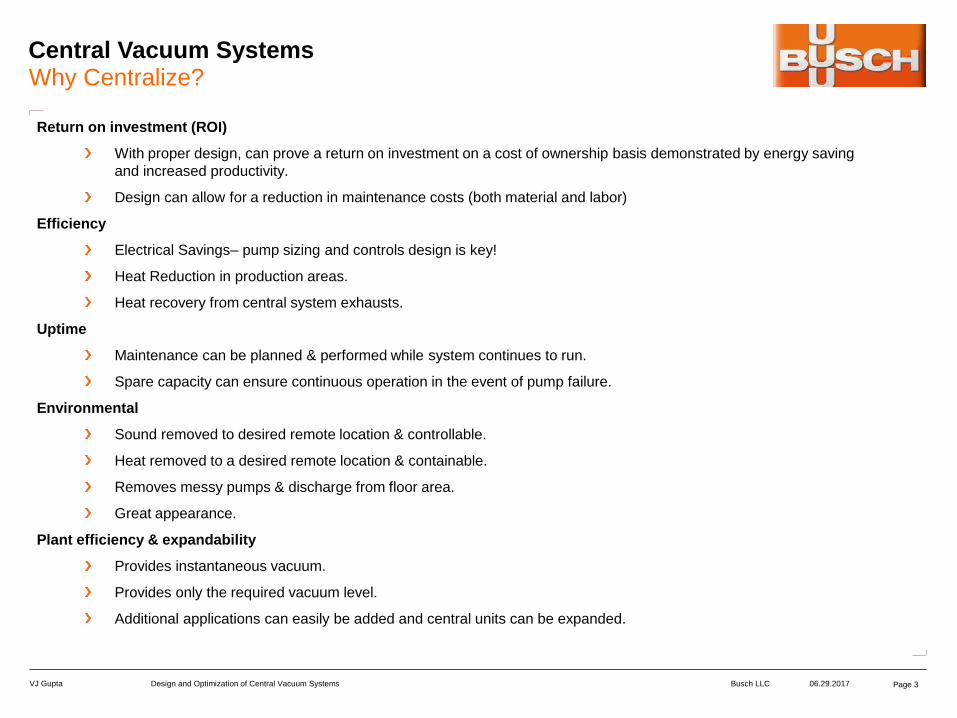
Central Vacuum SystemsWhy Centralize?
Return on investment (ROI)
With proper design, can prove a return on investment on a cost of ownership basis demonstrated by energy saving
and increased productivity.
Design can allow for a reduction in maintenance costs (both material and labor)
Efficiency
Electrical Savings– pump sizing and controls design is key!
Heat Reduction in production areas.
Heat recovery from central system exhausts.
Uptime
Maintenance can be planned & performed while system continues to run.
Spare capacity can ensure continuous operation in the event of pump failure.
Environmental
Sound removed to desired remote location & controllable.
Heat removed to a desired remote location & containable.
Removes messy pumps & discharge from floor area.
Great appearance.
Plant efficiency & expandability
Provides instantaneous vacuum.
Provides only the required vacuum level.
Additional applications can easily be added and central units can be expanded.
Page 3

VJ Gupta Busch LLCDesign and Optimization of Central Vacuum Systems 06.29.2017
Central Vacuum SystemsShould I Centralize?
Conduct a Study
Conduct a dedicated study. Every customer’s requirements are unique.
Centralization must be done right to realize optimum savings. Not all applications are a
good fit.
Does my plant have multiple machines with different vacuum needs?
Does my plant require different vacuum levels (up to one, two or even three different
vacuum levels)?
Is my vacuum process Dynamic, Static or Both?
One preset vacuum pressure design (i.e. VFD) for plants with different vacuum level needs
may not be optimal.
Examples of varying vacuum levels in different industries:
Page 4

VJ Gupta Busch LLCDesign and Optimization of Central Vacuum Systems 06.29.2017
Vacuum System Design OptionsShould I Centralize?
Example of Varying Vacuum Levels in a Plant:
To Centralize these two applications, add standard flows:
Total standard flow needed = 9.5 SCFM + 58.5 SCFM = 68 SCFM
But, Central System be designed to operate at the maximum vacuum level needed, i.e.
18”HgV (303 Torr)
Resulting Pump Suction Flow @ 18”HgV = 170 ACFM
Equivalent to a 170 CFM Pump with a 10.0 HP motor!!
Printing Machine (Feeder): 24 ACFM Dry Vane Pump
Motor Power: 2.0 HP
Pump Suction Pressure: 18”HgV (303 Torr)
Pump Suction Flow: 24 ACFM (standard flow = 9.5 SCFM)
Trimming Machine: 100 cfm Side Channel Blower
Motor Power: 1.0 HP
Pump Suction Pressure: 3”HgV (684 Torr)
Pump Suction Flow: 65 ACFM (standard flow = 58.5 SCFM)
Page 5

VJ Gupta Busch LLCDesign and Optimization of Central Vacuum Systems 06.29.2017
Vacuum System Design OptionsPossibilities – Various Pump Technologies Available
MANY
OPERATING
PRINCIPLES
Dry Screw
Vacuum Pumps
Rotary Lobe
Blowers
Liquid Ring
Vacuum Pumps
Dry Claw
Vacuum Pumps
Oil-Lubricated
Rotary Vane
Vacuum Pumps
Side-Channel
Blowers
And Many
More!!
Each Operating Principle has its Optimum Vacuum Operating Range wherein it provides Maximum Efficiency!
Consider All Options!
Pick the Best Fit
Page 6

VJ Gupta Busch LLCDesign and Optimization of Central Vacuum Systems 06.29.2017
Vacuum System Design OptionsStarters & Controls Hardware
Starter Panel
w/ On/Off Switches
Control Panel
w/o VFD
Control Panel
w/ VFD
Less PPE (Personal Protective
Equipment) means less downtime!
Page 7

VJ Gupta Busch LLCDesign and Optimization of Central Vacuum Systems 06.29.2017
Vacuum System Design OptionsVacuum Control
Pick the right Controls Scheme. Simply installing VFD alone does not guarantee maximum
savings.
Consider cascading control logic with ON/OFF switch points for single or multiple pump
configurations. This has been a very successful practice in the industry for a long time.
Consider using a VFD to “trim” excess capacity for more energy savings.
Central systems connected to large flow machines can cause significant vacuum “spikes”.
VFD may be unable to keep up! Vacuum buffers can be considered.
Chose optimum Pipe Size and Pipe Volume considering costs, pressure drop and system
dynamics.
Additional vacuum buffers can be added (i.e. tanks, larger piping etc.)
Page 8

VJ Gupta Busch LLCDesign and Optimization of Central Vacuum Systems 06.29.2017
Central Vacuum SystemsIn Summary
Every Customer’s plant requirements are unique.
There is no “One Size Fits All” solution! An Optimal Centralized System is custom
tailored to meet customer needs.
Conduct a complete study of your existing needs. Busch can help with this!
Pick the pump technology that is designed for your vacuum level and application.
Central systems can look very different from one another!
The Optimum Control Scheme is key to a successful design. VFD can be used
where it makes sense!
Take advantage of Vacuum Buffer and Pipe Sizing to optimize performance.
Central systems have to be custom tailored to meet your requirements.
Contact an expert!
Page 9

VJ Gupta Busch LLCDesign and Optimization of Central Vacuum Systems 06.29.2017
Design and Optimization of Central Vacuum SystemsContact Us
Thank you!
For more information about Busch Vacuum Pumps and Systems, please
visit: www.buschusa.com
VJ Gupta
Systems Engineering Manager for Busch USA
Office: (757) 502-7084 • Cell: (757) 373-0099
Page 10

Thank you for attending!
The recording and slides of this webinar will be made available to attendees via email later today.
PDH Certificates will be e-mailed to Attendees within two days.
For your free subscription, please visit http://www.blowervacuumbestpractices.com/magazine/subscription.
Sponsored by

Thursday, July 27, 2017 – 2:00 PM ESTRegister for free at: www.airbestpractices.com/magazine/webinars
Hank van Ormer, Air Power USAKeynote Speaker
July 2017 Webinar:
Reducing Use: Leak Inspection Programs