Embed Size (px)
Citation preview
Evaluation Kit for AD7152, Ultralow Power Capacitance Converter
EVAL-AD7152
Rev. 0 Evaluation boards are only intended for device evaluation and not for production purposes. Evaluation boards are supplied “as is” and without warranties of any kind, express, implied, or statutory including, but not limited to, any implied warranty of merchantability or fitness for a particular purpose. No license is granted by implication or otherwise under any patents or other intellectual property by application or use of evaluation boards. Information furnished by Analog Devices is believed to be accurate and reliable. However, no responsibility is assumed by Analog Devices for its use, nor for any infringements of patents or other rights of third parties that may result from its use. Analog Devices reserves the right to change devices or specifications at any time without notice. Trademarks and registered trademarks are the property of their respective owners. Evaluation boards are not authorized to be used in life support devices or systems.
One Technology Way, P.O. Box 9106, Norwood, MA 02062-9106, U.S.A.Tel: 781.329.4700 www.analog.com Fax: 781.461.3113 ©2008 Analog Devices, Inc. All rights reserved.
GENERAL DESCRIPTION This data sheet describes the AD7152 evaluation board and PC software.
Additional details about the AD7152, an ultralow power, 2-channel capacitance-to-digital converter (CDC) can be found at www.analog.com.
More information about the Analog Devices, Inc., family of CDC products can be found at www.analog.com/CDC.
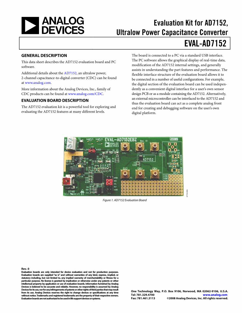
EVALUATION BOARD DESCRIPTION The AD7152 evaluation kit is a powerful tool for exploring and evaluating the AD7152 features at many different levels.
The board is connected to a PC via a standard USB interface. The PC software allows the graphical display of real-time data, modification of the AD7152 internal settings, and generally assists in understanding the part features and performance. The flexible interface structure of the evaluation board allows it to be connected in a number of useful configurations. For example, the digital section of the evaluation board can be used indepen-dently as a convenient digital interface for a user’s own sensor design PCB or as a module containing the AD7152. Alternatively, an external microcontroller can be interfaced to the AD7152 and thus the evaluation board can act as a complete analog front end for creating and debugging software on the user’s own digital platform.
0772
4-00
1
Figure 1. AD7152 Evaluation Board
EVAL-AD7152
Rev. 0 | Page 2 of 12
TABLE OF CONTENTS General Description ......................................................................... 1
Evaluation Board Description ......................................................... 1
Revision History ............................................................................... 2
Evaluation Software Installation ..................................................... 3
Evaluation Board Hardware ............................................................ 4
Power Supply ................................................................................. 4
I2C Interface Configuration Options ......................................... 4
Evaluation Board Software .............................................................. 5
Starting the Evaluation Software ................................................ 5
Real-Time Mode ........................................................................... 5
Setting up the AD7152 .................................................................6
Analysis Mode ...............................................................................8
Evaluation Board Schematic and Artwork .....................................9
Schematic........................................................................................9
Component ID ............................................................................ 10
Layout .......................................................................................... 10
Ordering Information .................................................................... 11
Bill of Materials ........................................................................... 11
Ordering Guide .......................................................................... 11
ESD Caution................................................................................ 11
REVISION HISTORY 8/08—Revision 0: Initial Version

EVAL-AD7152
Rev. 0 | Page 3 of 12
EVALUATION SOFTWARE INSTALLATION The AD7152 evaluation board software must be installed before connecting the AD7152 evaluation board to the PC.
0772
4-00
2
Figure 2. AD7152 Evaluation Kit CD
1. Insert the AD7152 evaluation kit CD in the CD-ROM drive of your PC. The evaluation software installation wizard should start automatically after inserting the CD. If the wizard does not start, run Setup.exe from the AD7152 evaluation kit CD.
0772
4-00
3
Figure 3. AD7152 Evaluation Software Installation
2. Follow the steps in the evaluation software installation wizard until the installation is completed.
3. Connect the AD7152 evaluation board to your PC USB connector using the USB cable included in the evaluation kit. The POWER LED on the evaluation board turns on and the Found New Hardware Wizard starts automatically on the PC.
0772
4-00
4
Figure 4. Found New Hardware Wizard
4. Follow the steps in the Found New Hardware Wizard window. If a message that the software has not passed Windows® Logo testing, click Continue Anyway.
0772
4-00
5
Figure 5. Windows Logo Warning
5. Follow the steps in the Found New Hardware Wizard until the installation is completed.

EVAL-AD7152
Rev. 0 | Page 4 of 12
EVALUATION BOARD HARDWARE POWER SUPPLY To use the AD7152 evaluation board, make sure that the AVDD link (LK1) is in place, either in 3.3 V when using the on-board voltage supply or in V_EXT when using an external voltage source via J2.
In both cases, the LED labeled POWER on the board should turn on when connected to either of the supply sources.
I2C INTERFACE CONFIGURATION OPTIONS The AD7152 evaluation board allows different digital interface configurations by redirecting the I2C® signals, SDA and SCL, on LK2.
Default
Links in the SDA and SCL positions of LK2 connect the USB microcontroller as the I2C bus master to the on-board AD7152, as shown in Figure 6. This allows easy use of the evaluation board together with the PC software.
μ C
LK2
U2U1
SDA
SCL
AD7152 EVAL BOARD
AD7152AD7152MICRO-CONTROLLER
0772
4-00
6
Figure 6. AD7152 Evaluation Board in Default Configuration
USB—External Connection
The AD7152 evaluation board allows customers to connect their own specific AD7152 application board to Pin 6 and Pin 8 of LK2. This enables customers, together with the PC evaluation software, to evaluate their application hardware using the AD7152 evaluation board only as a USB-to-I2C digital interface as shown in Figure 7.
μ C
LK2
U2U1
SDA
SCL
AD7152 EVAL BOARD
AD7152AD7152MICRO-CONTROLLER
FINAL APPLICATION
SDA
SCL
AD7152
0772
4-00
7
Figure 7. AD7152 Evaluation Board as USB-to-I2C interface
External Connection—AD7152
The AD7152 evaluation board can be used for software develop-ment by connecting a customer-specific external microcontroller board to Pin 5 and Pin 7 of LK2, as shown in Figure 8, using the AD7152 CDC on the evaluation board as the sensing device.
μ C
LK2
U2U1
SDA
SCL
AD7152 EVAL BOARD
AD7152AD7152MICRO-CONTROLLER
SDA
SCL
CUSTOMER BOARD
MICRO-CONTROLLER
0772
4-00
8
Figure 8. AD7152 Evaluation Board Software Development Platform
EVAL-AD7152
Rev. 0 | Page 5 of 12
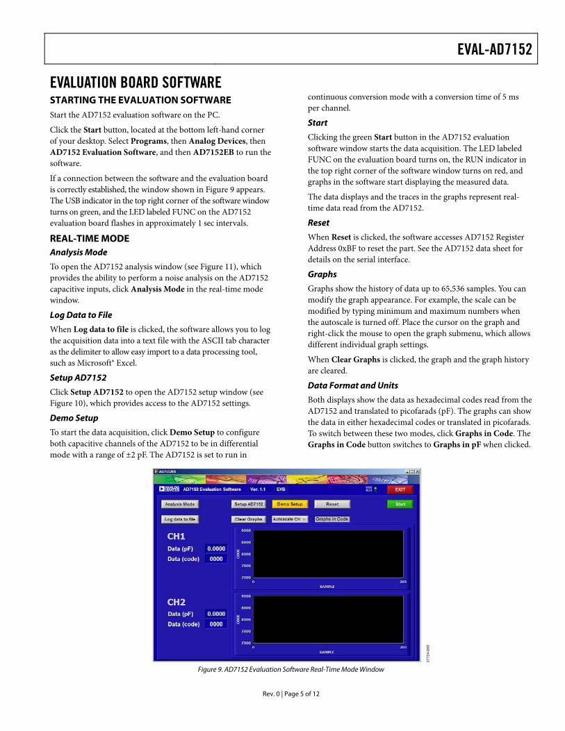
EVALUATION BOARD SOFTWARE STARTING THE EVALUATION SOFTWARE Start the AD7152 evaluation software on the PC.
Click the Start button, located at the bottom left-hand corner of your desktop. Select Programs, then Analog Devices, then AD7152 Evaluation Software, and then AD7152EB to run the software.
If a connection between the software and the evaluation board is correctly established, the window shown in Figure 9 appears. The USB indicator in the top right corner of the software window turns on green, and the LED labeled FUNC on the AD7152 evaluation board flashes in approximately 1 sec intervals.
REAL-TIME MODE Analysis Mode
To open the AD7152 analysis window (see Figure 11), which provides the ability to perform a noise analysis on the AD7152 capacitive inputs, click Analysis Mode in the real-time mode window.
Log Data to File
When Log data to file is clicked, the software allows you to log the acquisition data into a text file with the ASCII tab character as the delimiter to allow easy import to a data processing tool, such as Microsoft® Excel.
Setup AD7152
Click Setup AD7152 to open the AD7152 setup window (see Figure 10), which provides access to the AD7152 settings.
Demo Setup
To start the data acquisition, click Demo Setup to configure both capacitive channels of the AD7152 to be in differential mode with a range of ±2 pF. The AD7152 is set to run in
continuous conversion mode with a conversion time of 5 ms per channel.
Start
Clicking the green Start button in the AD7152 evaluation software window starts the data acquisition. The LED labeled FUNC on the evaluation board turns on, the RUN indicator in the top right corner of the software window turns on red, and graphs in the software start displaying the measured data.
The data displays and the traces in the graphs represent real-time data read from the AD7152.
Reset
When Reset is clicked, the software accesses AD7152 Register Address 0xBF to reset the part. See the AD7152 data sheet for details on the serial interface.
Graphs
Graphs show the history of data up to 65,536 samples. You can modify the graph appearance. For example, the scale can be modified by typing minimum and maximum numbers when the autoscale is turned off. Place the cursor on the graph and right-click the mouse to open the graph submenu, which allows different individual graph settings.
When Clear Graphs is clicked, the graph and the graph history are cleared.
Data Format and Units
Both displays show the data as hexadecimal codes read from the AD7152 and translated to picofarads (pF). The graphs can show the data in either hexadecimal codes or translated in picofarads. To switch between these two modes, click Graphs in Code. The Graphs in Code button switches to Graphs in pF when clicked.
0772
4-00
9
Figure 9. AD7152 Evaluation Software Real-Time Mode Window

EVAL-AD7152
Rev. 0 | Page 6 of 12
SETTING UP THE AD7152
0772
4-01
0
Figure 10. AD7152 Evaluation Software Setup Window
Register Field
The register section of the setup window (left portion of the window) indicates the address, register name, and the current content in hexadecimal and binary form for each AD7152 register.
Read
When Read is clicked, the evaluation software reads the current register content of the AD7152 registers and the updates are shown in the setup window.
Write
When Write is clicked, the evaluation software writes the current settings shown in the setup window into the AD7152 registers.
Reset
When Reset is clicked, the software accesses AD7152 Register Address 0xBF to reset the part. See the AD7152 data sheet for details on the serial interface.
OK
When OK is clicked, the evaluation software writes the current settings into the AD7152 registers, the setup window closes, and the software returns to the real-time mode window.
Cancel
When Cancel is clicked, the evaluation software writes the register settings that were buffered from the time the setup window was opened into the AD7152 registers, regardless of whether Write was clicked previously. The setup window then closes and the software returns to the real-time mode window.
Conv Time
From the Conv Time box, you can select from the following conversion times (single channel or dual channel):
• 5 ms/200 Hz or 10 ms/100 Hz • 20 ms/50 Hz or 40 ms/25 Hz • 50 ms/20 Hz or 100 ms/10 Hz • 60 ms/16.7 Hz or 120 ms/8.33 Hz
Operating Mode
The Operating Mode box allows you to put the AD7152 into the following operating modes:
• Standby mode (idle). Part is fully powered up, but not performing any conversion.
• Continuous conversion. Part is repeatedly performing conversions on the enabled channel(s). If two channels are enabled, the part is sequentially switching between them.
• Single conversion. Part performs a single conversion on the enabled channel. If two channels are enabled, the part performs two conversions, one on each channel. After finishing the conversion(s), the part goes to standby mode (idle).
• Power-down. Powers down the on-chip circuits, except the digital interface.
Single Conversion Loop
You can operate the AD7152 repetitively in single conversion mode by clicking Single Conversion Loop. The AD7152 returns into standby mode (idle) when the acquisition is stopped.

EVAL-AD7152
Rev. 0 | Page 7 of 12
This mode of operation was implemented to compensate for possible coupling effects between the SCL signal of the I2C interface and the CIN2(−) signal due to their close proximity on chip.
Offset Calibration
Note that the AD7152 cannot perform an offset calibration with both channels enabled.
When Offset Calibration is clicked, the evaluation software performs a sequential offset calibration if both channels are enabled; otherwise, it performs an offset calibration on the enabled channel.
Capacitive Input Setting.
By clicking Channel1 or Channel2, the evaluation software allows you to enable or disable the capacitive input channels individually.
The Range box allows you to select the following capacitive input ranges for each channel depending on the input selected mode (differential or single ended):
• ±2 pF or 4 pF • ±1 pF or 2 pF • ±0.5 pF or 1 pF • ±0.25 pF or 0.5 pF
The Mode box allows you to select between differential mode and single-ended mode.
Note that the change of input mode requires an offset calibration for that channel.
In differential mode, the AD7152 requires an offset of 0x8000, with 0x0000 representing negative full scale and 0xFFF0 representing positive full-scale.
In single-ended mode, the AD7152 requires an offset of 0x3000, with 0x0000 representing 0 pF and 0xFFF0 representing full scale.
CAPDAC
When DAC+ or DAC− is clicked, you can enable the CAPDACs to allow compensation for capacitive offsets (nonchanging).
You can set the required capacitive offset by using the DAC Value up and down arrows to bring the measurement back into the capacitive input range.
EVAL-AD7152
Rev. 0 | Page 8 of 12
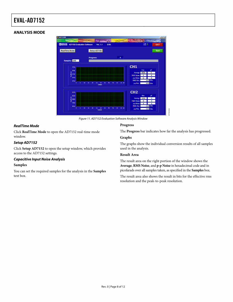
ANALYSIS MODE
0772
4-01
1
Figure 11. AD7152 Evaluation Software Analysis Window
RealTime Mode
Click RealTime Mode to open the AD7152 real-time mode window.
Setup AD7152
Click Setup AD7152 to open the setup window, which provides access to the AD7152 settings.
Capacitive Input Noise Analysis
Samples
You can set the required samples for the analysis in the Samples text box.
Progress
The Progress bar indicates how far the analysis has progressed.
Graphs
The graphs show the individual conversion results of all samples used in the analysis.
Result Area
The result area on the right portion of the window shows the Average, RMS Noise, and p-p Noise in hexadecimal code and in picofarads over all samples taken, as specified in the Samples box.
The result area also shows the result in bits for the effective rms resolution and the peak-to-peak resolution.

EVAL-AD7152
Rev. 0 | Page 9 of 12
EVALUATION BOARD SCHEMATIC AND ARTWORK SCHEMATIC
07724-012
Figure 12. AD7152 Evaluation Board Schematic—Analog Part

EVAL-AD7152
Rev. 0 | Page 10 of 12
COMPONENT ID
0772
4-01
3
Figure 13. AD7152 Evaluation Board Layout—Silkscreen
LAYOUT
0772
4-01
4
Figure 14. AD7152 Evaluation Board Layout—Component Side
07
724-
015
Figure 15. AD7152 Evaluation Board Layout—Bottom Side

EVAL-AD7152
Rev. 0 | Page 11 of 12
ORDERING INFORMATION BILL OF MATERIALS Table 1. Reference Designator Qty. Description Manufacturer Part No. PCB 1 2-layer FR4 PCB,1.6 mm × 75 mm × 115 mm Analog Devices EVAL-AD7152EBZ U1, Sample1, Sample2 3 CDC for capacitive sensing, 10-lead MSOP Analog Devices AD7152BRMZ U2 1 Voltage regulator, 3.3 V, low quiescent current,
8-lead SOIC Analog Devices ADP3303ARZ-3.3
U3 1 Microcontroller, EZ-USB FX2LP™, 56-lead QFN Cypress CY7C68013A-56LFXC U4 1 EEPROM, I2C, 64 kB, 8-lead SOIC Microchip 24LC64-I/SN C1, C2, C5, C10 to C22 16 Capacitor ceramic, 0.1 μF, 16 V, X7R, 0603 Murata GRM188R71C104K C3, C4 2 Capacitor ceramic, 1 μF, 16 V, X7R, 0805 Murata GRM21BR71C105K C6, C7 2 Capacitor ceramic, 12 pF, 50 V, COG, 0603 Murata GRM1885C1H120J C8, C9, C23, C24 4 Capacitor ceramic, 10 μF, 4 V, X5R, 0603 Murata GRM188R60G106M D1 1 LED, green, 0805 Avago HSMG-C170 D2 1 LED, red, 0805 Avago HSMS-C190 D3 1 Diode, VRRM = 50 V, IF(AV) = 1.5 A, SMB Vishay S2A J1 1 Connector, USB Mini-B, SMD Molex 0548190572 J2 1 Two-way terminal block, pitch 5 mm Camden Electronics CTB5000/2 L1 1 300 Ω @ 100 MHz, ferrite bead, 0805 TDK MMZ2012D301B LK1 1 Header, straight, pitch 2.54 mm, 2 × 2 pin Harwin M20-9980246 LK2 1 Header, straight, pitch 2.54 mm, 2 × 5 pin Harwin M20-9980546 P1 to P3, P5 to P7 6 Connector, SMB, 50 Ω, PCB, straight Amphenol SMB1251B1-3GT30G-50 R4, R5 2 Resistor, 0 Ω, 0603 Phycomp 232270296001 R6 2 Resistor, 1.5 Ω, 5%, 0603 Phycomp 232270260158 R7, R8 2 Resistor, 1.0 kΩ, 1%, 0603 Phycomp 232270461002 R9, R10 2 Resistor, 2.2 kΩ, 1%, 0603 Phycomp 232270462202 R12, R13, R14 4 Resistor, 100 kΩ, 1%, 0603 Phycomp 232270461004 Y2 1 Crystal, 24 MHz, 12 pF, CMS-8 series ECS ECS-240-12-20A-TR
ORDERING GUIDE Model Description EVAL-AD7152EBZ1 Evaluation Board 1 Z = RoHS Compliant Part.
ESD CAUTION

EVAL-AD7152
Rev. 0 | Page 12 of 12
NOTES
Purchase of licensed I2C components of Analog Devices or one of its sublicensed Associated Companies conveys a license for the purchaser under the Philips I2C Patent Rights to use these components in an I2C system, provided that the system conforms to the I2C Standard Specification as defined by Philips.
©2008 Analog Devices, Inc. All rights reserved. Trademarks and registered trademarks are the property of their respective owners. EB07724-0-8/08(0)