Embed Size (px)
Citation preview

ETSI TR 101 987 V1.1.1 (2001-08)Technical Report
Terrestial Trunked Radio (TETRA);Proposed Air Interface Enhancements
for TETRA Release 2;Analysis and Feasibility Assessment
ETSI
ETSI TR 101 987 V1.1.1 (2001-08)2
ReferenceDTR/TETRA-02062
KeywordsTETRA, air interface, radio
ETSI
650 Route des LuciolesF-06921 Sophia Antipolis Cedex - FRANCE
Tel.: +33 4 92 94 42 00 Fax: +33 4 93 65 47 16
Siret N° 348 623 562 00017 - NAF 742 CAssociation à but non lucratif enregistrée à laSous-Préfecture de Grasse (06) N° 7803/88
Important notice
Individual copies of the present document can be downloaded from:http://www.etsi.org
The present document may be made available in more than one electronic version or in print. In any case of existing orperceived difference in contents between such versions, the reference version is the Portable Document Format (PDF).
In case of dispute, the reference shall be the printing on ETSI printers of the PDF version kept on a specific network drivewithin ETSI Secretariat.
Users of the present document should be aware that the document may be subject to revision or change of status.Information on the current status of this and other ETSI documents is available at http://www.etsi.org/tb/status/
If you find errors in the present document, send your comment to:[email protected]
Copyright Notification
No part may be reproduced except as authorized by written permission.The copyright and the foregoing restriction extend to reproduction in all media.
© European Telecommunications Standards Institute 2001.All rights reserved.
ETSI
ETSI TR 101 987 V1.1.1 (2001-08)3
Contents
Intellectual Property Rights ..........................................................................................................................5
Foreword......................................................................................................................................................5
1 Scope..................................................................................................................................................6
2 References ..........................................................................................................................................6
3 Abbreviations .....................................................................................................................................6
4 Executive Summary............................................................................................................................84.1 General Overview ....................................................................................................................................... 84.2 Conclusions and Recommendation .............................................................................................................. 8
5 Work Areas ........................................................................................................................................95.1 General ....................................................................................................................................................... 95.2 Improving spectrum efficiency, capacity, and system performance............................................................... 95.2.1 General.................................................................................................................................................. 95.2.2 Improved Handover ............................................................................................................................... 95.2.2.1 Background...................................................................................................................................... 95.2.2.2 No Standard Changes...................................................................................................................... 115.2.2.3 Minor Standard Changes................................................................................................................. 125.2.2.4 Major Standard Changes................................................................................................................. 135.2.3 Hierarchical Cell Structures.................................................................................................................. 155.2.3.1 Introduction.................................................................................................................................... 155.2.3.2 Macrocells vs. Microcells ............................................................................................................... 155.2.3.3 Requirements for Hierarchical Cell Structures................................................................................. 165.2.4 Frequency Hopping and Fractional Loading ......................................................................................... 165.2.4.1 Introduction.................................................................................................................................... 165.2.4.2 Benefits of Frequency Hopping....................................................................................................... 175.2.4.3 The way forward ............................................................................................................................ 185.3 Improving terminal characteristics ............................................................................................................. 195.3.1 General................................................................................................................................................ 195.3.2 Improved Battery Life - Energy Economy Mode................................................................................... 195.3.2.1 Introduction.................................................................................................................................... 195.3.2.2 Performance of First Generation Handsets....................................................................................... 195.3.3 Improved Battery Life - Discontinuous Transmission ........................................................................... 205.3.3.1 Introduction.................................................................................................................................... 205.3.3.2 Performance of First Generation Handsets....................................................................................... 205.3.3.3 Additional Standardization Work .................................................................................................... 215.3.4 Improved Battery Life - Open and Closed Loop Power Control............................................................. 225.3.4.1 General........................................................................................................................................... 225.3.4.2 Methodology .................................................................................................................................. 225.3.4.3 Reduced Power Control Step Size (Open Loop) .............................................................................. 225.3.4.4 Increased Power Control Dynamic Range (Open Loop)................................................................... 235.3.4.5 Changing From Open to Closed Loop ............................................................................................. 235.3.4.6 Closed Loop in a Fast Rayleigh Fade Environment.......................................................................... 245.3.4.7 Closed Loop Power Control Rate .................................................................................................... 245.3.5 RF Characteristics................................................................................................................................ 245.3.5.1 General........................................................................................................................................... 245.3.5.2 Power mask.................................................................................................................................... 245.4 Optimization of frame structures & protocols............................................................................................. 245.4.1 Protocol Enhancements ........................................................................................................................ 245.4.1.1 Introduction.................................................................................................................................... 245.4.1.2 The Physical layer .......................................................................................................................... 255.4.1.3 The MAC layer............................................................................................................................... 255.4.1.4 The LLC layer ................................................................................................................................ 255.4.1.5 Layer 3 protocols............................................................................................................................ 285.4.2 Reduced Speech Delay......................................................................................................................... 29
ETSI
ETSI TR 101 987 V1.1.1 (2001-08)4
5.4.3 Recommendations................................................................................................................................ 305.5 User requirements implementation issues................................................................................................... 305.5.1 General................................................................................................................................................ 305.5.2 TETRA LCS (Location Service)........................................................................................................... 305.5.2.1 Background.................................................................................................................................... 305.5.2.2 Location dependent services (LDS)................................................................................................. 315.5.2.3 Location issues related to TETRA................................................................................................... 315.5.2.4 Location Accuracy and Update Rates for Emergency Service Users................................................. 325.5.2.5 Location methods ........................................................................................................................... 335.5.2.6 Summary........................................................................................................................................ 355.5.3 Extended Range Capability .................................................................................................................. 365.5.3.1 General........................................................................................................................................... 365.5.3.2 Aeronautical ................................................................................................................................... 365.5.3.3 Linear cells..................................................................................................................................... 375.5.3.4 Large rural cells (Rural Telephony / Telemetry) .............................................................................. 385.5.3.5 Technical Means of Achieving Extended Range.............................................................................. 38
6 Feasible Options and Enhancements Phases ......................................................................................396.1 OPTIONS ................................................................................................................................................. 396.1.1 Sub-area 1............................................................................................................................................ 396.1.2 Sub-area 2............................................................................................................................................ 406.1.3 Sub-area 3............................................................................................................................................ 406.1.4 Sub-area 4............................................................................................................................................ 416.2 Options by phase....................................................................................................................................... 416.2.1 Phase 1 ................................................................................................................................................ 416.2.1.1 Sub-area 1 options .......................................................................................................................... 416.2.1.2 Sub-area 2 options .......................................................................................................................... 416.2.1.3 Sub-area 3 options .......................................................................................................................... 426.2.1.4 Sub-area 4 options .......................................................................................................................... 426.2.2 Phase 2 ................................................................................................................................................ 426.2.2.1 Sub-area 1 options .......................................................................................................................... 426.2.2.2 Sub-area 2 options .......................................................................................................................... 426.2.2.3 Sub-area 3 options .......................................................................................................................... 426.2.2.4 Sub-area 4 options .......................................................................................................................... 426.2.3 Phase 3 ................................................................................................................................................ 436.2.3.1 Sub-area 1 options .......................................................................................................................... 436.2.3.2 Sub-area 2 options .......................................................................................................................... 436.2.3.3 Sub-area 3 options .......................................................................................................................... 436.2.3.4 Sub-area 4 options .......................................................................................................................... 436.3 Enhancements timeline.............................................................................................................................. 43
7 Other options ....................................................................................................................................447.1 General ..................................................................................................................................................... 447.2 Sub-area 1................................................................................................................................................. 447.2.1 Unfeasible options ............................................................................................................................... 447.2.2 Unstudied options ................................................................................................................................ 447.3 Sub-area 2................................................................................................................................................. 447.4 Sub-area 3................................................................................................................................................. 447.4.1 Unfeasible Options............................................................................................................................... 447.4.2 Unstudied options ................................................................................................................................ 457.5 Sub-area 4................................................................................................................................................. 457.5.1 Unfeasible options ............................................................................................................................... 457.5.2 Unstudied options ................................................................................................................................ 45
Annex A: Options vs. Requirements Matrix....................................................................................46
Annex B: Bibliography.....................................................................................................................47
History .......................................................................................................................................................48
ETSI
ETSI TR 101 987 V1.1.1 (2001-08)5
Intellectual Property RightsIPRs essential or potentially essential to the present document may have been declared to ETSI. The informationpertaining to these essential IPRs, if any, is publicly available for ETSI members and non-members, and can be foundin ETSI SR 000 314: "Intellectual Property Rights (IPRs); Essential, or potentially Essential, IPRs notified to ETSI inrespect of ETSI standards", which is available from the ETSI Secretariat. Latest updates are available on the ETSI Webserver (http://www.etsi.org/ipr).
Pursuant to the ETSI IPR Policy, no investigation, including IPR searches, has been carried out by ETSI. No guaranteecan be given as to the existence of other IPRs not referenced in ETSI SR 000 314 (or the updates on the ETSI Webserver) which are, or may be, or may become, essential to the present document.
ForewordThis Technical Report (TR) has been produced by ETSI Project Terrestrial Trunked Radio (TETRA).
ETSI
ETSI TR 101 987 V1.1.1 (2001-08)6
1 ScopeThe present document analyses and provides recommendations regarding Air Interface enhancements that have beenproposed for TETRA Release 2. The target audience is EPT, and the purpose is to enable informed decisions to be madeby EPT regarding prioritization and feasibility of AI enhancement standardization work, and workload division betweenWG2, WG3, and other WGs as applicable.
The TETRA air interface has been designed to meet the special requirements of TETRA and as such it is more effectiveand efficient at meeting these requirements than other radio systems. However it is necessary that TETRA shouldcontinue to evolve in line with technology enhancements so that it remains a class-leading technology. There are manypotential enhancements which could be added to the TETRA air interface, and it is necessary for the TETRAcommunity to evaluate which combination of these best meets the needs of TETRA whilst not requiring excessivestandardization effort. A number of proposed enhancements have been considered, resulting in this technical report.Effort has been made, during the analysis and feasibility assessment work, to consider a maximum number of proposedenhancements which have been put forth in relevant forums regarding TETRA Release 2.
2 ReferencesFor the purposes of this Technical Report (TR), the following references apply:
[1] ETSI EN 300 392-2 (V2.3.2): "Terrestrial Trunked Radio (TETRA); Voice plus Data (V+D);Part 2: Air Interface (AI)".
3 AbbreviationsFor the purposes of the present document, the following abbreviations apply:
AACH Access Assignment CHannelAI Air InterfaceAoA Angle of ArrivalASCCH Assigned Secondary Control CHannelAVL Automatic Vehicle LocationBER Bit Error rateBNCH Broadcast Network CHannelBS Base StationBSCH Broadcast Synchronization CHannelCB Control uplink BurstCC Call ControlC/I Carrier to Interference ratioCHAP Challenge Handshake Authentication ProtocolCLCH Common Linearization CHannelCMCE Circuit Mode Control EntityCODEC COder/DECoderDC Direct CurrentDTX Discontinuous TransmissionEIRP Equivalent Isotropic Radiated PowerEL Event LabelE-OTD Enhanced Observed Time DifferenceEPT ETSI Project TETRAERC European Radio CommitteeES Enhanced ServicesFCC Federal Communications CommissionFCS Frame Check SequenceFEC Forward Error CorrectionFER Frame Erasure rateFH Frequency HoppingFRH Fast Reselection Hysteresis
ETSI
ETSI TR 101 987 V1.1.1 (2001-08)7
FRT Fast Reselection ThresholdGPS Global Positioning SystemGSM Global System for Mobile communicationsHCS Hierarchical Cell StructuresHGO HanG OverID IDentityIOP InterOPerabilityIP Internet ProtocolLA Location AreaLCS LoCation ServiceLDS Location Dependant ServiceLIF Location Interoperability ForumLLC Logical Link Control (TETRA L2)LMU Location Management UnitMAC Medium Access Control (TETRA L2)MCCH Main Control CHannelMM Mobility ManagementMoU Memorandum of UnderstandingMS Mobile StationNUB Normal Uplink BurstOTAR Over The Air Re-keyingOTD Observed Time DifferencePA Power AmplifierPDCH Packet Data CHannelPDO Packet Data OptimizedPDU Protocol Data UnitPTT Press To TalkQoS Quality of ServiceRF Radio FrequencyRSS Received Signal StrengthRSSI Received Signal Strength IndicatorRTD Round Time DelayRTT Round Time TripRX Receive(r)SACH Slow Access CHannelSAP Service Access PointSCH/HD Signalling CHannel/Half slot DownlinkSDS Short Data ServiceS/N Signal to NoiseSNDCP Sub-Network Dependent Convergence ProtocolSRH Slow Reselection HysteresisSRT Slow Reselection ThresholdSS Supplementary ServiceSSI Short Subscriber IdentitySTCH STealing CHannelSTF Specialist Task ForceSwMI Switching and Management InfrastructureTA Timing AdvanceTCH Traffic CHannelTDMA Time Division Multiple AccessTETRA TErrestrial Trunked RAdioTIP Tetra Interoperability ProfileTL-SDU SDU from the service user (i.e. MLE)TMA-SAP TETRA MAC sub layer A - Service Access PointTM-SDU SDU from the layer above MAC (i.e. LLC)TMO Trunked Mode OperationToA Time of ArrivalTX Transmit(ter)UMTS Universal Mobile Telecommunications SystemV+D Voice plus DataVAD Voice Activity DetectionWG ÉPT Working Group
ETSI
ETSI TR 101 987 V1.1.1 (2001-08)8
4 Executive Summary
4.1 General OverviewTG23 was formed as a joint EPT WG2/WG3 task group to perform the voluntary feasibility study work for AIenhancements for TETRA Release 2. Seven meetings were held between November 2000 and June 2001, withparticipation from at least ten different member organizations. Additionally, TETRA Release 2 user requirements inputwas solicited by liaison statement from WG1 and TETRA MoU WG ES, with ES providing input on Extended Rangeand Location Services. The WG1 user requirements survey results were not available in time to be incorporated into thepresent document, but it is expected those results will be considered in time by the WGs and by the EPT ManagementCommittee.
The AI enhancement options are organized into "enhancement packages" according to their interdependence inproducing a potential benefit to the TETRA Release 2 AI. Based on these enhancement packages, four correspondingsub-areas of TG23 were formed, with the following issues and leaders:
1) Improving spectrum efficiency, capacity, and system performance - Dr. Glyn Carter (Dolphin) [includesconsideration of C/I measurements, Improved power control, Measurement reporting, Improved handover,Frequency hopping, Fractional loading, Hierarchical cell structures]
2) Improving terminal characteristics - Andy Noy (Dolphin) [includes consideration of Improved power control,Improved handover, Discontinuous TX.]
3) Optimization of frame structures & protocols - Colin Fletcher (Marconi) [includes consideration ofIncorporation of additional voice codecs, Optimization of frame structures]
4) User requirements issues - Ken Oborne (BT Airwave) [includes consideration of Timing equalization,Triangulation techniques]
Analysis of the enhancement feasibility was done at TG23 meetings, within member organizations, and viacorrespondence on the TG23 exploder.
The most feasible TETRA Release 2 AI options are mapped onto the standardization timeline using the TETRA Release2 WG2 work programme timeline as a reference. Since different options may require different levels of standardizationwork, the options are divided into three categories, called phases (see table 1). The phases are defined based on theestimated standardization work needed to implement a given option in the present document.
Table 1: Definition of the phases
Phase Definition1 Significant benefit with little or no standardization effort. Includes TIPS, and
enhancements requiring minor changes to standard mainly to clarifyimplementations.
2 Expected benefits and some standardization costs. Some more study may beneeded before consideration.
3 Potential (unestablished) benefits, unknown standardization or implementationcosts. Significantly more study may be needed before consideration.
Note that the sub-areas and phases are independent.
The phases of standardization were mapped according to the timeline in clause 6.3.
4.2 Conclusions and RecommendationThe TETRA Release 2 AI enhancements options are divided into three categories based on the level of cost vs. benefitfor the given option. The categories are phase 1, phase 2, and phase 3.
It is recommended that TETRA Release 2 standardization work for the feasible options requiring standardization listedin clause 6 be carried out according to the phase categorizations (clause 6.2) and phase timeline (clause 6.3).
ETSI
ETSI TR 101 987 V1.1.1 (2001-08)9
Phase 1 options that are already enabled in the current standards, and do not require further standardization (e.g., TIPissues such as discontinuous transmission), are recommended to be implemented in TETRA Release 2 systems.
AI enhancement options which were not considered, or were deemed unviable (clause 7), could be studied further inlater phases of TETRA Release 2 standardization work in accordance with member interest and resource availability.
It is also recommended that STF resources be considered on some of the options, in particular those on phase 3.
5 Work Areas
5.1 GeneralDuring the enhancements analysis it was found that many of the enhancements could be grouped into "enhancementpackages" based on their interdependence in producing a benefit(s). The work was divided accordingly into fourdifferent sub-areas based on the groupings, and to map to the TETRA Release 2 primary objectives.
The results of the work in the sub-areas are described below.
NOTE: Clause numbers in brackets refer to ETS 300 392-2, the Air Interface Standard for TETRA 1.
5.2 Improving spectrum efficiency, capacity, and systemperformance
5.2.1 General
This clause describes results of analysis and feasibility assessment of enhancements including consideration of C/Imeasurements, improved power control, measurement reporting, improved handover, frequency hopping, fractionalloading and hierarchical cell structures.
5.2.2 Improved Handover
5.2.2.1 Background
This clause of the present document has been prepared to advance suggestions for improving the existing handovermechanisms in TETRA. Handover has to be considered for an MS, which is idle, engaged in a circuit mode call orpacket data session. Some parameters apply to only one state whereas others apply to an MS in either state (Both). Itlooks at changes to the current methodology and breaks them into three categories. Those that make use of existingstandard signalling with no change, those that need minor changes and those that need major changes.
Current TETRA networks suffer from the following problems caused by the existing handover techniques. It should benoted that these problems are only observed for an MS involved in a circuit mode call. In future MSs in idle mode andin packet data sessions will need to be considered in addition to those in circuit mode calls. The first two are giving themost problems today, but may not be the most important in future.
1) Handover to a wrong cell, which has the same MCCH frequency as a neighbour cell. The MS then loses allsensible neighbours as it gets information on neighbours to the "wrong" cell.
2) Cell dragging by an MS, where frequency reuse is reduced by interference of the transmitting MS with othersthat would otherwise be out of range.
3) Load management - Handover to a cell with calls queued for a TCH will cause at least temporary loss of traffic.
4) Need for consistent behaviour from all MS suppliers.
5) Need for (future) flexibility in the handover methodology.
ETSI
ETSI TR 101 987 V1.1.1 (2001-08)10
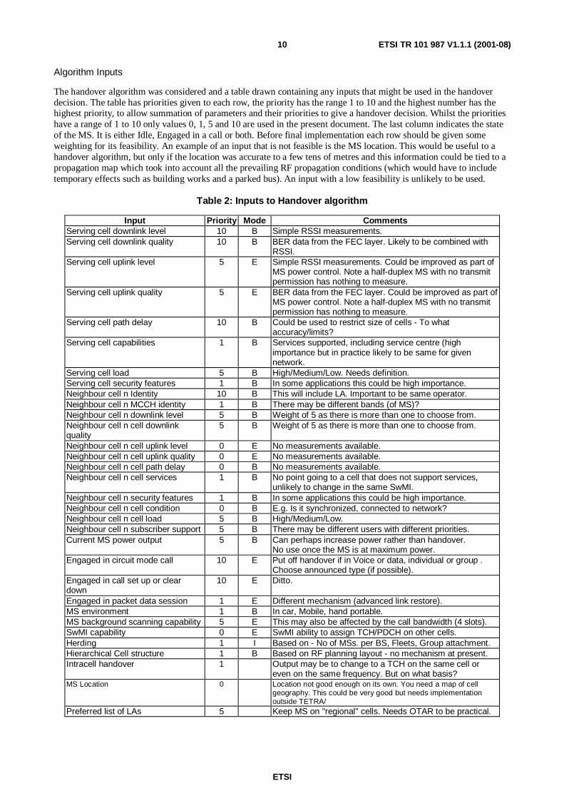
Algorithm Inputs
The handover algorithm was considered and a table drawn containing any inputs that might be used in the handoverdecision. The table has priorities given to each row, the priority has the range 1 to 10 and the highest number has thehighest priority, to allow summation of parameters and their priorities to give a handover decision. Whilst the prioritieshave a range of 1 to 10 only values 0, 1, 5 and 10 are used in the present document. The last column indicates the stateof the MS. It is either Idle, Engaged in a call or both. Before final implementation each row should be given someweighting for its feasibility. An example of an input that is not feasible is the MS location. This would be useful to ahandover algorithm, but only if the location was accurate to a few tens of metres and this information could be tied to apropagation map which took into account all the prevailing RF propagation conditions (which would have to includetemporary effects such as building works and a parked bus). An input with a low feasibility is unlikely to be used.
Table 2: Inputs to Handover algorithm
Input Priority Mode CommentsServing cell downlink level 10 B Simple RSSI measurements.Serving cell downlink quality 10 B BER data from the FEC layer. Likely to be combined with
RSSI.Serving cell uplink level 5 E Simple RSSI measurements. Could be improved as part of
MS power control. Note a half-duplex MS with no transmitpermission has nothing to measure.
Serving cell uplink quality 5 E BER data from the FEC layer. Could be improved as part ofMS power control. Note a half-duplex MS with no transmitpermission has nothing to measure.
Serving cell path delay 10 B Could be used to restrict size of cells - To whataccuracy/limits?
Serving cell capabilities 1 B Services supported, including service centre (highimportance but in practice likely to be same for givennetwork.
Serving cell load 5 B High/Medium/Low. Needs definition.Serving cell security features 1 B In some applications this could be high importance.Neighbour cell n Identity 10 B This will include LA. Important to be same operator.Neighbour cell n MCCH identity 1 B There may be different bands (of MS)?Neighbour cell n downlink level 5 B Weight of 5 as there is more than one to choose from.Neighbour cell n cell downlinkquality
5 B Weight of 5 as there is more than one to choose from.
Neighbour cell n cell uplink level 0 E No measurements available.Neighbour cell n cell uplink quality 0 E No measurements available.Neighbour cell n cell path delay 0 B No measurements available.Neighbour cell n cell services 1 B No point going to a cell that does not support services,
unlikely to change in the same SwMI.Neighbour cell n security features 1 B In some applications this could be high importance.Neighbour cell n cell condition 0 B E.g. Is it synchronized, connected to network?Neighbour cell n cell load 5 B High/Medium/Low.Neighbour cell n subscriber support 5 B There may be different users with different priorities.Current MS power output 5 B Can perhaps increase power rather than handover.
No use once the MS is at maximum power.Engaged in circuit mode call 10 E Put off handover if in Voice or data, individual or group .
Choose announced type (if possible).Engaged in call set up or cleardown
10 E Ditto.
Engaged in packet data session 1 E Different mechanism (advanced link restore).MS environment 1 B In car, Mobile, hand portable.MS background scanning capability 5 E This may also be affected by the call bandwidth (4 slots).SwMI capability 0 E SwMI ability to assign TCH/PDCH on other cells.Herding 1 I Based on - No of MSs. per BS, Fleets, Group attachment.Hierarchical Cell structure 1 B Based on RF planning layout - no mechanism at present.Intracell handover 1 Output may be to change to a TCH on the same cell or
even on the same frequency. But on what basis?MS Location 0 Location not good enough on its own. You need a map of cell
geography. This could be very good but needs implementationoutside TETRA/
Preferred list of LAs 5 Keep MS on "regional" cells. Needs OTAR to be practical.
ETSI
ETSI TR 101 987 V1.1.1 (2001-08)11
5.2.2.2 No Standard Changes
This clause looks at changes that could be made to improve the handover efficiency with no changes to the standard.The changes are operational and implementation. Some of these implementational aspects could be considered forannexes to EN 300 392-2 [1] or inclusion into the TIP process.
Operational Changes
Handover Parameters
TETRA specifies a range of parameters to be used in handover, in all MS modes. These parameters are broadcast by theSwMI, to all MSs. The last two are used to calculate a variable called C1, the others are used directly in the handovermechanism.
The following parameters are set by the operator and can vary on a cell-by-cell basis.
1) Slow Reselection Threshold (SRT) with a range of 0 - 30 dB
2) Slow Reselection Hysteresis (SRH) with a range of 0 - 30 dB
3) Fast Reselection Threshold (FRT) with a range of 0 - 30 dB
4) Fast Reselection Hysteresis (FRH) with a range of 0 - 30 dB
5) Minimum MS Rx level (Rxlev_access_min) with a range of 50 - 125 dB
6) Maximum MS Tx power (MS_TxPwr_Max_Cell) with a range of 15 - 45 dB
These parameters will have an effect on the MS behaviour using the current handover mechanism. It might be possibleto have a set of values recommended for different types of cell (e.g. Dense, urban and rural).
Radio Downlink Failure
Radio downlink failure will force the MS to change cell using unannounced handover.
Each cell broadcasts a parameter called "Radio_Downlink_Timeout". This is used as an initial and maximum value ofan up/down counter used in detecting radio link failure using good and bad decoding of the AACH (The AACH is alogical channel on every downlink slot. It has 14 data bits, which are expanded to 30 by FEC). The up/down counter isdecremented by 16 for a lost slot and incremented by 4 for a good slot (the values are defined as default but there is noway of changing these over the air interface). If the counter should reach zero the link is declared broken.
The initial value parameter needs research into its range and value. It could be used on a cell-by-cell basis todifferentiate the different types of cell.
Implementation Changes
RSSI or Equivalent
Throughout EN 300 392-2 [1] the measurements are defined as "RSSI or equivalent". It is recommended that anequivalent that takes into account the error rate as well as the absolute signal strength.
Dynamic Change of Parameters
If the SwMI could change parameters it could effectively change a "rural" cell into a "dense" cell by changing the valueof broadcast parameters. This could be linked to cell conditions such as loading or temporary reduction in power forservicing.
Maximum Path Delay
Outside the C1 calculation there is a parameter for maximum path delay (10.3.3). This is internal to the SwMI but couldalso be set on a cell-by-cell basis. Currently it can only indicate a radio link failure (21.5.3) in a MAC resource PDU.
It is recommended to check how current SwMI implementations set this parameter and what its range can be. Thisparameter could be useful in restricting the size of any cell.
ETSI
ETSI TR 101 987 V1.1.1 (2001-08)12
Consistent Behaviour
The different suppliers have different algorithms for cell reselection of all types (initial, idle, in call) There could bemore co-operation among suppliers to give them all the same behaviour, which would in turn give them marketadvantage in a multi-vendor environment.
5.2.2.3 Minor Standard Changes
This clause looks at changes that could be made to improve the handover efficiency with minor changes to the standard.
Downlink RSSI measurement
Currently 10.3.1 defines the accuracy of RSS measurement to be +/-4 dB. Other clauses (23.7.3) hint at ways ofsampling and measurement methodology but there is no absolute definition of RSS measurement methodology. It isrecommended that this methodology should be standardized so that different MSs would use the same method formeasuring RSS. Indeed the RSS equivalent could be defined so as to take some account of link quality, rather thanreceived power only. If possible the measured value should be to a better accuracy than +/-4 dB. This should all go intoclause 10.3 as downlink signal quality may be used for functionality other than handover.
This would make it possible to have more accurate settings for the cell broadcast parameters and the differentiation ofthe different cell types (rural, etc.).
Colour Code
Currently the neighbour colour codes are not broadcast. This means the MS can lock onto a MCCH from a non-neighbour cell and pick up the colour code from the BSCH. The MS can then decode all information on the wrong cell.It might be advantageous to add the neighbour colour code to a broadcast message. The MS would then be able todecode the valid MCCH only.
LA Identifier in the Uplink
Currently 16.9.3.4 has an optional element in the U-location Update demand called LA information.
If this element were mandatory, the MS could include it to prevent registering on the "wrong" cell with a co-channelMCCH. The SwMI would see a location update with the wrong LA (not a broadcast neighbour) and could reject therequest with a reject cause of "LA not allowed" (or a new reason). The standard currently says the MS should initiatecell reselection for "LA not allowed". There could be improvement for this procedure in the handover case.
Cell Service Level
The parameter "cell Service Level" in 18.5.5 needs definition of what is meant by "high, medium and low".
We suggest the following:
High no free TCH
Medium n % free TCH
Low m % free TCH
The values of n and m are likely to around be 20 and 60 respectively. These values will be based on traffic statistics ofthe BS and may need standard definitions, at least the "high".
Near Radio Link Failure Indication
Currently EN 300 392-2 has defined methods of indicating both downlink and uplink failure.
Downlink
For the downlink there is an internal (modelling) message described in 23.7.3.1. The measurement is based on anup/down counter, which is set to an initial value on channel acquisition.
The improvement suggested here is to have another value (say 50 %) which will give an indication the downlink isdetecting errors but is not bad enough to be declared as failed. Such a change would have no impact on the air interfaceand only affect internal MS modelling. The information would be sent to the MM layers in a similar report message.
ETSI
ETSI TR 101 987 V1.1.1 (2001-08)13
NOTE 1: This would affect the serving cell only unless the MS camped on neighbours (rather than monitored).
Uplink
Uplink quality measurement is more difficult in TETRA than GSM. If an MS is receiving in a half duplex call(individual or group) it is not allowed to transmit and so there is no data available for uplink quality. Note that uplinkquality only applies to an MS transmitting on a U plane traffic channel. It does not apply to an MS in idle or packet datamode. Even for a full duplex individual call there could be a "service interaction" issue with discontinuous transmission,which may be introduced to improve battery life. Again the uplink would not be so readily available for measurement.
That said, the uplink measurements are described in 23.7.3.2, where the BS can indicate uplink failure as part of theclosed loop power control.
The improvement suggested is to change one value of the power control element (21.5.3) to the "nearly bad uplink".This in turn would mean losing one of the step change values.
It also means making the implementation of the power control element mandatory.
NOTE 2: This would affect the serving cell only as the MS will never transmit on neighbours.
Near Maximum Path Delay
In the same way as the above two cases the signalling could indicate that the path delay is near its maximum.
The improvement would be to change one value of the power control element (21.5.3) to the "near maximum pathdelay". This in turn would mean losing one of the step change values.
It also means making the implementation of the power control element mandatory.
NOTE 3: This would affect the serving cell only as the MS will never transmit on neighbours.
5.2.2.4 Major Standard Changes
This clause suggests improvements that will need non-trivial changes to the TETRA standard. The changes in the maininvolve new PDUs on the air interface and new procedures to use the signalling.
Changes to PDUs and new PDUs will need additional research into any effect on loading of the MCCH, FACCH andSACCH of the serving cell. Any loading of the FACCH will have a detrimental impact on the voice quality.
Uplink Quality Report PDU
If the measures described above (in the power control element) are not enough to get the uplink quality information tothe MS, the SwMI could send uplink quality measurements to the MS in a new PDU.
NOTE 1: The SwMI has nothing to measure in half duplex calls (individual or group) where the MS does not havetransmit permission and part of duplex calls using discontinuous transmission.
SwMI Controlled Handover
There are suggested changes that tackle the foreseen problems of consistent behaviour and changes of the algorithm.The only way to realistically solve these two problems is to have the algorithm in the SwMI. This in turn leads to newrequirements for signalling and procedural definitions.
Signalling
The new signalling requirements fall into five categories.
Broadcast
The SwMI would have to broadcast the fact that the MS should not use its internal algorithms to determine handover. Itshould rather wait for the polling and cell change commands. Research is needed into which broadcast message is usedand to ensure there is a spare bit that can be used.

ETSI
ETSI TR 101 987 V1.1.1 (2001-08)14
Poll MS for Downlink Measurements
A new signal is needed to ask a particular MS for its downlink measurements and any other handover related input (seetable 2).
Report Downlink Measurements
A new signal is needed, used by the MS to report its inputs needed for the handover algorithm in the SwMI. One ofthese is the RSS measured on the downlink by the MS.
To reduce excessive air interface signalling the MS must rank neighbour cells prior to replying to the poll. This willdepend on the actual information needed by the SwMI and the size of the slot used (half or full).
SwMI Initiated Cell change Command
A new signal is needed to force an MS to move to another cell. Note there is already a command that could be used tomove MSs to a TCH on the same cell (14.5.3.2).
This new signal would have to include the identity of the new cell. Other information that may be needed includestransmit permission, queuing indication, registration and authentication information. The exact contents will bedetermined by the procedures defined.
NOTE 2: In half duplex calls (including group) calls the MS may not be able to transmit this PDU, except in frame18 where it will have to compete with other services (SDS) and possibly other MSs in the same group.
SwMI Initiated Cell change Command Response
The MS will have to respond to the change command., it may even be able to reject the command for some reason.
Procedures
It will be "outside the scope" how the SwMI decides which MS to put under consideration for handover and subsequentpoll action. Although "outside the scope" this will need a lot of consideration to see the benefits of this new signalling.
For an MS in a half-duplex call without transmit permission the poll may not be answered for some seconds. The MSwill have to wait for frame 18 and this report will have to compete with any other signalling. The uplink may have to beunacknowledged (no BL_ACK) as several downlink slots are used for broadcasts.
This may affect algorithms in the SwMI.
A new type of handover procedure will need to be defined. This will in effect be an unannounced type 2 where the MSmoves without telling the SwMI. Procedures will need to be defined so the MS behaves in a consistent manner.
• Does the MS monitor neighbours all the time or on the poll command?
• Can the MS reject the change command?
• Is registration implicit?
• Is registration included in the Cell change command?
• Is registration performed at the end of the call on the new cell?
• How would authentication work?
• How would air interface encryption work?
• What about the colour code?
• Where does the MS respond to the Cell change command (old or new cell)? Again note the problems that willexist in half duplex calls for an MS without transmit permission.
The SwMI must support all types of handover, even if the broadcast says handover should be SwMI initiated.
The SwMI must be able to support ignoring of the poll and cell change commands by "old" MSs.
ETSI
ETSI TR 101 987 V1.1.1 (2001-08)15
5.2.3 Hierarchical Cell Structures
5.2.3.1 Introduction
Mobile users vary in speed, use and density. It is not unusual to find environments that range from very high trafficdensity hotspots to very sparsely distributed users. The following two examples show typical cases for mobile userprofiles:
• Low speed, high use and high density such as pedestrians in "hot spots".
• High speed, low use and low density such as in-vehicle users.
Obviously there are conflicting requirements for these two types of users. Whereas the former requires small cells withhigh capacity, the latter requires large cells with low capacity. Hierarchical cell structures provide an efficient way toservice the different user types.
One example of using hierarchical cell structures is to have a layer of large cells (Macrocells or Macro layer) to satisfycoverage requirements with as few cells as possible, and then to put Microcells (small cells with high capacity) in hotspots to satisfy capacity requirements in these areas. The choice of which layer to use for a particular user dependsentirely on the mobile user characteristics (e.g. speed, use, density of users in that area, type of call).
5.2.3.2 Macrocells vs. Microcells
The macro layer is a layer of large cells intended to satisfy coverage requirements with as few cells as possible. Macrobase stations transmit high power, and their antennas are fitted on masts above average roof top level to achievemaximum coverage possible.
On the other hand, microcells are small cells intended to satisfy capacity requirements in hot spots. Microcells can onlyexist wherever needed, and they do not have to be contiguous. Micro base stations transmit relatively low power, andtheir antennas are fitted at low heights such as lamp posts (below average roof top level).
Since macrocell antennas are above average building level, the signal tends to travel long distances. Therefore,interference from macrocells travels long distances before it falls below an acceptable level. However, microcellantennas are below the average height level, so the surrounding clutter attenuates the signal. Therefore, interferencefrom microcells gets contained within relatively short distances, and so frequencies can be reused more frequently in themicro layer resulting in more spectrum efficiency and more capacity.
Considerations for Hierarchical Cell Structures
Since the micro layer offers more spectrum efficiency (capacity per hertz) than the macro layer, mobiles must beencouraged to use microcells. However, a high-speed mobile user should be assigned to a macrocell, otherwisehandover rate will rise dramatically increasing the amount of signalling overhead. Besides, cell dragging and droppingrate will increase dramatically.
In GSM, in order to prevent a fast moving mobile station from handing over to a microcell, some degree ofdiscouragement is introduced into the handover process. When a microcell becomes one of the strongest carriers, atimer is started and the value of C1 (or C2) for that cell is reduced by a certain amount (TEMPORARY_OFFSET).Once the timer reaches a certain value (PENALTY_TIME), the value of C1 (or C2) is restored. The transition betweenthe two states is achieved in a linear fashion. The values of TEMPORARY_OFFSET and PENALTY_TIME arebroadcast for each of the neighbouring cells as part of the neighbouring cell information message.
NOTE: The equations governing the reselection process are described in GSM 05.08, clause 6.4.
ETSI
ETSI TR 101 987 V1.1.1 (2001-08)16
5.2.3.3 Requirements for Hierarchical Cell Structures
A few techniques can be employed to support hierarchical cell structures in TETRA. These techniques vary incomplexity, flexibility and reliability. At the bottom end, the ‘priority cell’ feature can be used to distinguish microcellsfrom macrocells. This will not require change to the standard but the flexibility and reliability of this feature will belimited.
On the other hand, if the TEMPORARY_OFFSET and PENALTY_TIME features are introduced, a multi-layerednetwork can be operated in a more flexible and reliable way. These features will allow a network operator to changethese parameters according to the layer (macro, micro, pico), size of cell and type of environment (urban, suburban,rural) to achieve optimum performance. These parameters might also be useful in performing load management.
In GSM, TEMPORARY_OFFSET is 3 bits and PENALTY_TIME is 5 bits. These can be added as two new entities inthe neighbour cell information element in the D-NWRK-BROADCAST PDU.
The Way Forward
Two methods were identified in the present document to enable the deployment of Hierarchical Cell Structures, theseare:
1) Use of the cell priority identifier (Exists in the BS Service Details element in the D-MLE-SYSINFO PDU) todistinguish between Macrocells and Microcells. In the handover algorithm, TEMPORARY_OFFSET andPENALTY_TIME will have to be given fixed values. This is not ideal, as these values would vary according tothe cell size and the environment. However, it offers a quick solution to enable the implementation ofHierarchical Cell Structures.
2) The second solution adds more flexibility to the implementation of HCS by broadcasting the values ofTEMPORARY_OFFSET and PENALTY_TIME on a cell-by-cell basis.
5.2.4 Frequency Hopping and Fractional Loading
5.2.4.1 Introduction
Frequency Hopping (FH) is a technique used in mobile communication systems to minimize the effect of bad links. Inthis text, a bad link is a link with low C/I. This would result in a poor quality speech in the case of speech calls, andhigh BER in the case of data connections.
By using proper frequency reuse, a good C/I should be guaranteed most of the time. Nevertheless, there will be somelinks with low C/I due to:
• log-normal fading affecting an MS at cell edge by attenuating the wanted signal and multiplying the interference.
• the MS getting out of its serving cell boundaries (i.e. cell dragging), and therefore being distant from its servingBS and close to a co-channel interferer.
If a mobile user falls into one of these situations in a non-FH system, he will have to suffer from a degraded link. Thedegradation of the link will depend on the distance to the serving BS, distance to the interferer and propagationconditions.
The advantage of frequency hopping is that the unfortunate user will suffer from the bad link for only a fraction of thetime. For instance, if 4 frequencies were used for FH, then the unfortunate user would suffer from the bad link for only1/4th of the time. The other users, however, would not be affected so badly by the bad link because they are most likelyto be:
• further away from the interferer, or
• closer to the serving BS, or
• having better shadowing conditions to the serving BS and the interferer.
This clause is divided into three clauses. Clause 1 gives an introduction to the benefits of Frequency Hopping. Clause 2outlines these benefits in some detail. Finally clause 3 draws some conclusions and recommendations.
ETSI
ETSI TR 101 987 V1.1.1 (2001-08)17
5.2.4.2 Benefits of Frequency Hopping
In Fast Fading Channels
A fast fading channel is characterized by deep fades (as much as -30 dB) for short periods of time. The period that anMS remains in a deep fade depends on the speed of the user and the operating frequency. In some circumstances, thisperiod can extend over a few TETRA frames.
By using FH, an MS is not likely to spend more than one TETRA frame in deep fade. For instance, if the MS werehopping over 4 frequencies with frequency separation of 1 MHz, fast fading characteristics of these four frequencieswould be highly de-correlated. Therefore, if an MS is in deep fade on one frequency, it is likely to get out of the fade ifhopped to another frequency.
Therefore, FH improves the MS performance in a fast fading channel.
In Slow Fading Channels
A slow fading channel is characterized by a log-normal distribution. Slow fading results from effects of shadowingwhich could strengthen or weaken the signal.
Effects of slow fading should be taken into account in radio planning a network by allowing for a slow fading margin.Log-normal fading is a statistical process, and therefore some instances would occur where the wanted signal path ishighly shadowed (or highly weakened) and the interference path is clear (or highly strengthened). This could degradethe C/I by as much as 20 dB. If the victim user is at the cell edge, the C/I in this case will probably be too low, resultingin a bad link. FH reduces the effect of this bad link by allowing the unfortunate user to alternate between a fewfrequencies.
If FH is not applied, once a channel is assigned, the user will be stuck with it even if it is highly interfered with fromanother co-channel interferer. In FH systems, the effect of this bad channel will be reduced since the unfortunate userwill use it for only a fraction of the time.
For instance, if an MS is hopping over 4 frequencies, the victim user will suffer the bad quality link for only 1/4th of thetime. The other users, however, will not be affected so badly by the bad link because they are most likely to be:
• further away from the interferer, or
• closer to the serving BS, or
• having better shadowing conditions to the serving BS and the interferer.
As an example, if a bad link results in a Frame Erasure Rate (FER) of 10 %, then hopping over 4 frequencies wouldreduce the error frames by 4, thus resulting in a FER of 2,5 %, making the link more acceptable.
In Partially Loaded Systems
Even in lightly loaded systems, there will be instances where a user (at cell edge or outside cell boundary) is sufferingfrom a bad link due to a close by co-channel interferer. The probability of this happening depends on the systemloading, the more the load the more the probability of bad links.
FH helps in averaging out the interference over the hopping carriers. In a non-FH system, some links will have lowinterference and some will have high interference. FH ensures that interference is averaged out over all links. Therefore,in a non-FH system, some links will be good and some will be bad, whereas in a FH system, all links will have"average" quality.
In a non-FH system, as the system becomes lightly loaded, there will still be instances of situations that will result inbad links. If a user is using a bad link, he does not benefit from the fact that the system is lightly loaded. However, in aFH system, as the system becomes less loaded, the average quality of the system improves. Quality improvement willbe felt by all links in the FH system.
ETSI
ETSI TR 101 987 V1.1.1 (2001-08)18
In Data Applications
TETRA permits the use of external interleaving on data channels. External interleaving separates consecutive bits overmany frames (e.g. 2, 4 or 8) so that if one frame gets corrupted (due to fast fading or a strong burst of interference), thenwhen the bits are re-ordered (or de-interleaved), bits from the corrupted frame are evenly distributed. In this situation,channel coding is more likely to recover the corrupted bits and improve the quality of the signal.
In non-FH systems, a bad link will result in all TETRA frames to be corrupted. In this situation, channel coding will beof little benefit. FH reduces the effect of the bad link by improving the efficiency of the channel coding. For instance, ifthe MS is hopping over 4 frequencies, one of which is suffering excessive interference, then only one out of fourTETRA frames will be corrupted. After the de-interleaving stage, the corrupted bits will be fairly evenly distributed,making it easier for the channel coding to recover them.
Therefore, the combination of FH and external interleaving will make channel coding more efficient in recovering thecorrupted bits transmitted on the bad link.
Fractional Loading
The concept of fractional loading relies on pushing FH too far (by hopping over too many carriers) in order to obtainhigh C/I that would be sufficient to reduce the frequency reuse factor. In fractional loading schemes, capacity gain fromthe reduction of frequency reuse exceeds the loss due to the fractional loading of carriers. It has been claimed that150 % net capacity gain can be obtained from fractional loading schemes.
5.2.4.3 The way forward
From the previous discussion, we can see significant benefits from Frequency Hopping. These benefits can besummarized as follows:
• averages out the received interference over all hopping frequencies.
• improves the quality of the signal in a fast fading channel by reducing the probability of having more than oneTETRA frame in deep fade.
• improves the quality of service for a user at cell edge or outside its cell boundary, who is receiving weak wantedsignal and strong interference, by making him use other "good" channels.
• the overall quality of service of the system improves as the system gets less loaded since the "average"interference will be less.
• if external interleaving is used (as in data applications), the effect of corrupted frequencies can be greatlyreduced by channel coding.
• frequency Hopping is a pre-requisite to Fractional Loading which "potentially" increases system capacity by150 %.
These benefits suggest that FH is a potentially powerful technique to improve the overall quality of the TETRA system.On the other hand, FH would require continuous Linearization of the TETRA PA. A change of carrier requires half aslot of linearization. Therefore, if FH is applied on every TETRA frame, 50 % of the useful traffic will be lost tolinearizing the TETRA PA.
Clearly, FH is not a quick win and therefore cannot be considered in the early phases of TETRA Release 2. The benefitsof implementing FH in TETRA will need to be evaluated and compared with the cost of its implementation andstandardization. Moreover, the need of PA linearization seems to be an issue that renders FH in TETRA unfeasible.This issue needs to be solved if FH is to be standardized and implemented in TETRA.
Since FH is not a quick win, any work associated with it should be carried out in the later phases of TETRA Release 2.Such work should investigate the complexity of the linearization problem, and decide whether the benefits of FHexceed its costs.
ETSI
ETSI TR 101 987 V1.1.1 (2001-08)19
5.3 Improving terminal characteristics
5.3.1 General
This clause describes results of analysis and feasibility assessment of enhancements which affect terminalcharacteristics.
5.3.2 Improved Battery Life - Energy Economy Mode
5.3.2.1 Introduction
One task of TG23 was to look for means of getting improved battery lifetime. One of the standard techniques forachieving this is to put the MS in a "sleep" state such that it is not monitoring control channel downlink framescontinuously, reducing current consumption. The TETRA air interface standard supports signalling exchanges betweenthe MS and SwMI in order to negotiate the number of frames for which the MS sleeps. This feature is called EnergyEconomy Mode.
5.3.2.2 Performance of First Generation Handsets
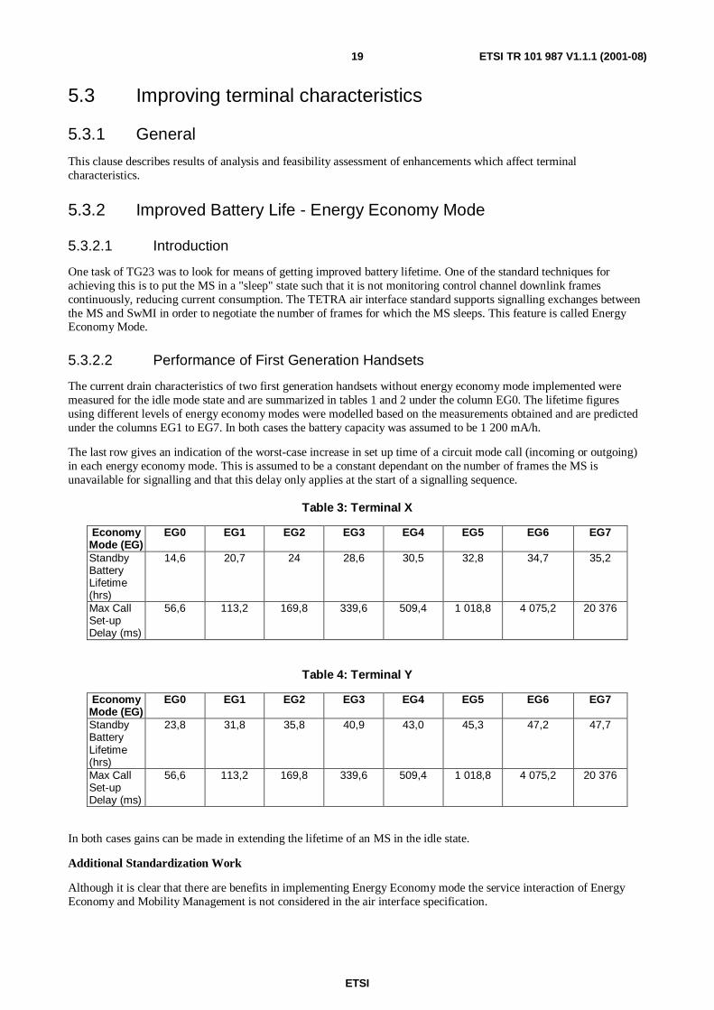
The current drain characteristics of two first generation handsets without energy economy mode implemented weremeasured for the idle mode state and are summarized in tables 1 and 2 under the column EG0. The lifetime figuresusing different levels of energy economy modes were modelled based on the measurements obtained and are predictedunder the columns EG1 to EG7. In both cases the battery capacity was assumed to be 1 200 mA/h.
The last row gives an indication of the worst-case increase in set up time of a circuit mode call (incoming or outgoing)in each energy economy mode. This is assumed to be a constant dependant on the number of frames the MS isunavailable for signalling and that this delay only applies at the start of a signalling sequence.
Table 3: Terminal X
EconomyMode (EG)
EG0 EG1 EG2 EG3 EG4 EG5 EG6 EG7
StandbyBatteryLifetime(hrs)
14,6 20,7 24 28,6 30,5 32,8 34,7 35,2
Max CallSet-upDelay (ms)
56,6 113,2 169,8 339,6 509,4 1 018,8 4 075,2 20 376
Table 4: Terminal Y
EconomyMode (EG)
EG0 EG1 EG2 EG3 EG4 EG5 EG6 EG7
StandbyBatteryLifetime(hrs)
23,8 31,8 35,8 40,9 43,0 45,3 47,2 47,7
Max CallSet-upDelay (ms)
56,6 113,2 169,8 339,6 509,4 1 018,8 4 075,2 20 376
In both cases gains can be made in extending the lifetime of an MS in the idle state.
Additional Standardization Work
Although it is clear that there are benefits in implementing Energy Economy mode the service interaction of EnergyEconomy and Mobility Management is not considered in the air interface specification.
ETSI
ETSI TR 101 987 V1.1.1 (2001-08)20
The longer the handset is "asleep" less neighbour cell information and monitoring can be obtained. It is recommended,to ensure a consistent level of MS performance within systems, that additional information is provided as guidelineswithin the air interface to cover:
• minimum levels of measurement criteria for ranking list on which cell reselection will be based.
• decision criteria on when possibly to leave energy economy mode in order to ensure measurement criteria is met,or possibly when to change to a lower level of energy economy mode to achieve a desired level of measurementcriteria.
Tables 1 and 2 also indicate the effect of energy economy mode on call set-up delay for incoming calls. This is widelyrecognized as being one of the trade-offs of this type of function but perhaps notes should be introduced within thestandard for other services such as SDS and packet data where QoS may be compromised.
5.3.3 Improved Battery Life - Discontinuous Transmission
5.3.3.1 Introduction
One task of TG23 was to look for means of getting improved battery lifetime. One of the standard techniques forachieving this is to only transmit during a speech call when there is voice activity, thus reducing current consumption.This mode of operation, known as Discontinuous Transmission (DTX), is usually only applicable to duplex calls, as theuser should be releasing PTT in semi-duplex calls when not talking! Both the TETRA air interface standard, and theCODEC standard support signalling exchanges between the MS and SwMI in order to use this feature.
5.3.3.2 Performance of First Generation Handsets
This clause contains results of investigations into potential power savings through discontinuous transmission.
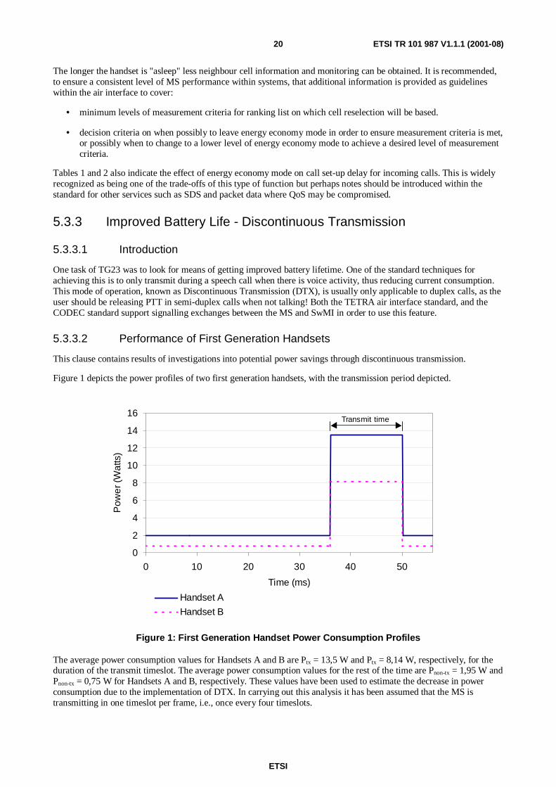
Figure 1 depicts the power profiles of two first generation handsets, with the transmission period depicted.
0
2
4
6
8
10
12
14
16
0 10 20 30 40 50
Time (ms)
Pow
er(
Wat
ts)
Handset A
Handset B
Transmit time
Figure 1: First Generation Handset Power Consumption Profiles
The average power consumption values for Handsets A and B are Ptx = 13,5 W and Ptx = 8,14 W, respectively, for theduration of the transmit timeslot. The average power consumption values for the rest of the time are Pnon-tx = 1,95 W andPnon-tx = 0,75 W for Handsets A and B, respectively. These values have been used to estimate the decrease in powerconsumption due to the implementation of DTX. In carrying out this analysis it has been assumed that the MS istransmitting in one timeslot per frame, i.e., once every four timeslots.
ETSI
ETSI TR 101 987 V1.1.1 (2001-08)21
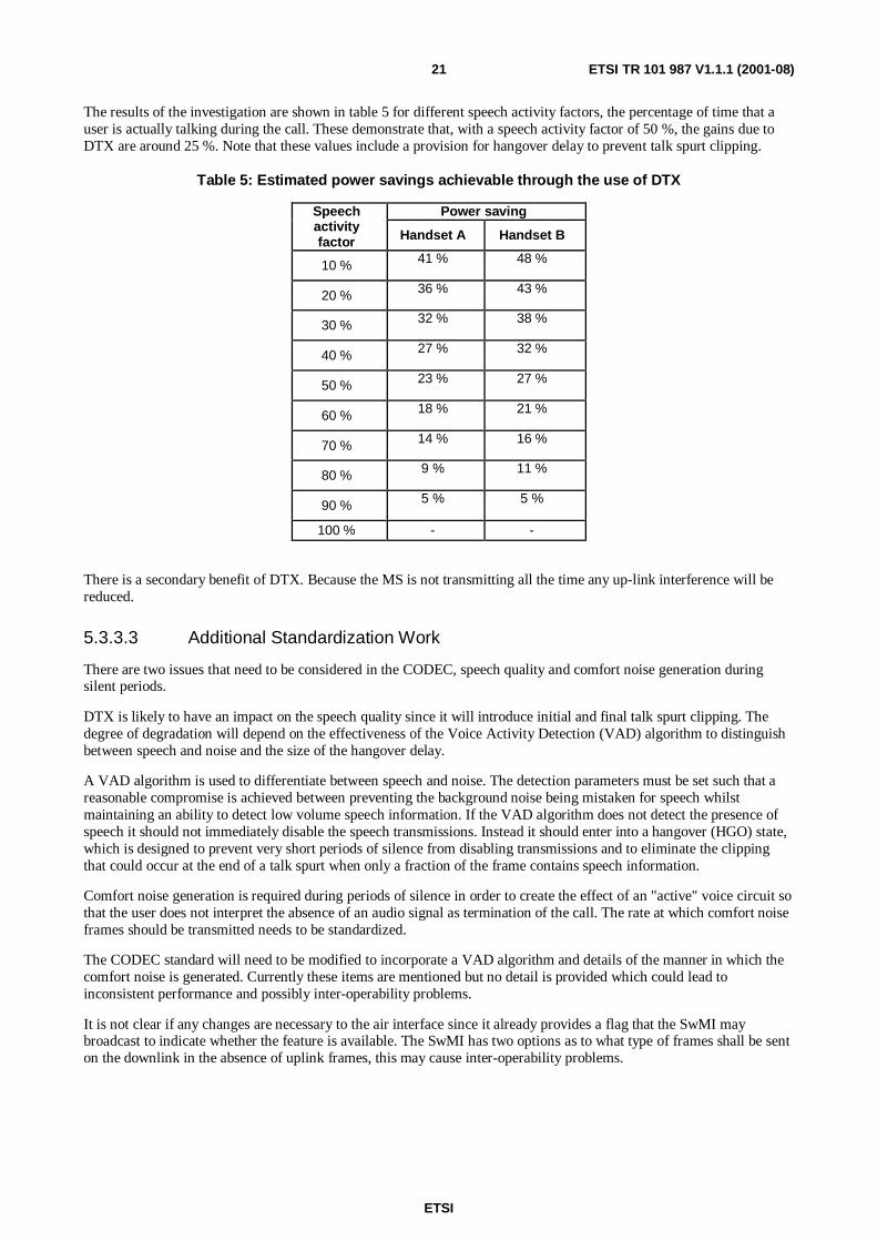
The results of the investigation are shown in table 5 for different speech activity factors, the percentage of time that auser is actually talking during the call. These demonstrate that, with a speech activity factor of 50 %, the gains due toDTX are around 25 %. Note that these values include a provision for hangover delay to prevent talk spurt clipping.
Table 5: Estimated power savings achievable through the use of DTX
Power savingSpeechactivityfactor Handset A Handset B
10 % 41 % 48 %
20 % 36 % 43 %
30 % 32 % 38 %
40 % 27 % 32 %
50 % 23 % 27 %
60 % 18 % 21 %
70 % 14 % 16 %
80 % 9 % 11 %
90 % 5 % 5 %
100 % - -
There is a secondary benefit of DTX. Because the MS is not transmitting all the time any up-link interference will bereduced.
5.3.3.3 Additional Standardization Work
There are two issues that need to be considered in the CODEC, speech quality and comfort noise generation duringsilent periods.
DTX is likely to have an impact on the speech quality since it will introduce initial and final talk spurt clipping. Thedegree of degradation will depend on the effectiveness of the Voice Activity Detection (VAD) algorithm to distinguishbetween speech and noise and the size of the hangover delay.
A VAD algorithm is used to differentiate between speech and noise. The detection parameters must be set such that areasonable compromise is achieved between preventing the background noise being mistaken for speech whilstmaintaining an ability to detect low volume speech information. If the VAD algorithm does not detect the presence ofspeech it should not immediately disable the speech transmissions. Instead it should enter into a hangover (HGO) state,which is designed to prevent very short periods of silence from disabling transmissions and to eliminate the clippingthat could occur at the end of a talk spurt when only a fraction of the frame contains speech information.
Comfort noise generation is required during periods of silence in order to create the effect of an "active" voice circuit sothat the user does not interpret the absence of an audio signal as termination of the call. The rate at which comfort noiseframes should be transmitted needs to be standardized.
The CODEC standard will need to be modified to incorporate a VAD algorithm and details of the manner in which thecomfort noise is generated. Currently these items are mentioned but no detail is provided which could lead toinconsistent performance and possibly inter-operability problems.
It is not clear if any changes are necessary to the air interface since it already provides a flag that the SwMI maybroadcast to indicate whether the feature is available. The SwMI has two options as to what type of frames shall be senton the downlink in the absence of uplink frames, this may cause inter-operability problems.
ETSI
ETSI TR 101 987 V1.1.1 (2001-08)22
5.3.4 Improved Battery Life - Open and Closed Loop Power Control
5.3.4.1 General
Improved Battery Life - Open and Closed Loop Power Control looks at the potential battery lifetime savings that couldbe achieved by smaller power control steps and closed loop power control.
A reduced lower limit for the dynamic range of power control was seen as not viable for battery life extension, howeverfor other reasons (e.g. form factor, pico cells and indoor use) this should be evaluated.
There is an additional benefit of improved power control in that the average transmitted power of an MS is reduced,resulting in improved system performance.
5.3.4.2 Methodology
It was assumed that a population of MSs is uniformly distributed over an idealized circular cell area with a fourth powerloss law.
The DC consumption was based on an MS being in simplex or duplex transmission 36 % and 8 % of the timerespectively.
For the open loop case the power saving afforded was evaluated using for a Log-Normal fading characteristic with astandard deviation of 0 to 9 dB and a margin sufficient for an availability of 95 %, where this fade is assumed to beslow enough to be tracked by the power control. The average of these results is reported here.
The open to closed loop case was evaluated assuming a significant amount of uplink and downlink loss difference,resulting from the differing transmit and receive frequencies, modelled as a Log-Normal distribution, again assuming amargin to give 95 % availability, and sufficient power control speed to follow the fade. The statistics applying hererequire further study.
In the case of the analysis of the loop update rate the mean distance between deep fade events due to knife-edgediffraction was estimated to arrive at an order of magnitude estimate of the required loop rate. The statistics here requirefurther study.
5.3.4.3 Reduced Power Control Step Size (Open Loop)
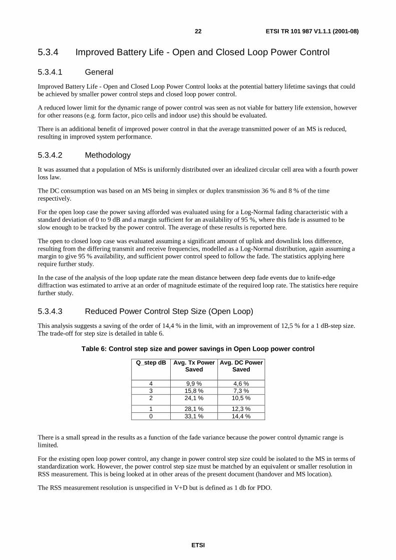
This analysis suggests a saving of the order of 14,4 % in the limit, with an improvement of 12,5 % for a 1 dB-step size.The trade-off for step size is detailed in table 6.
Table 6: Control step size and power savings in Open Loop power control
Q_step dB Avg. Tx PowerSaved
Avg. DC PowerSaved
4 9,9 % 4,6 %3 15,8 % 7,3 %2 24,1 % 10,5 %
1 28,1 % 12,3 %0 33,1 % 14,4 %
There is a small spread in the results as a function of the fade variance because the power control dynamic range islimited.
For the existing open loop power control, any change in power control step size could be isolated to the MS in terms ofstandardization work. However, the power control step size must be matched by an equivalent or smaller resolution inRSS measurement. This is being looked at in other areas of the present document (handover and MS location).
The RSS measurement resolution is unspecified in V+D but is defined as 1 db for PDO.
ETSI
ETSI TR 101 987 V1.1.1 (2001-08)23
5.3.4.4 Increased Power Control Dynamic Range (Open Loop)
This has a saving of an additional 2-3 %, particularly in environments with significant slow fade. However the issuessurrounding implementation of this are probably not worth surmounting for the available saving.
5.3.4.5 Changing From Open to Closed Loop
There are two mechanisms giving a saving that have been evaluated separately.
Link non-reciprocity may result is a significant improvement in Tx Power and DC power savings of up to 19-23 % inthe limit depending upon the degree of link non-reciprocity. For a 1 dB step size the saving would be 17-20 %, showinga significant improvement over the open loop case, assuming sufficiently fast fade tracking can be achieved.
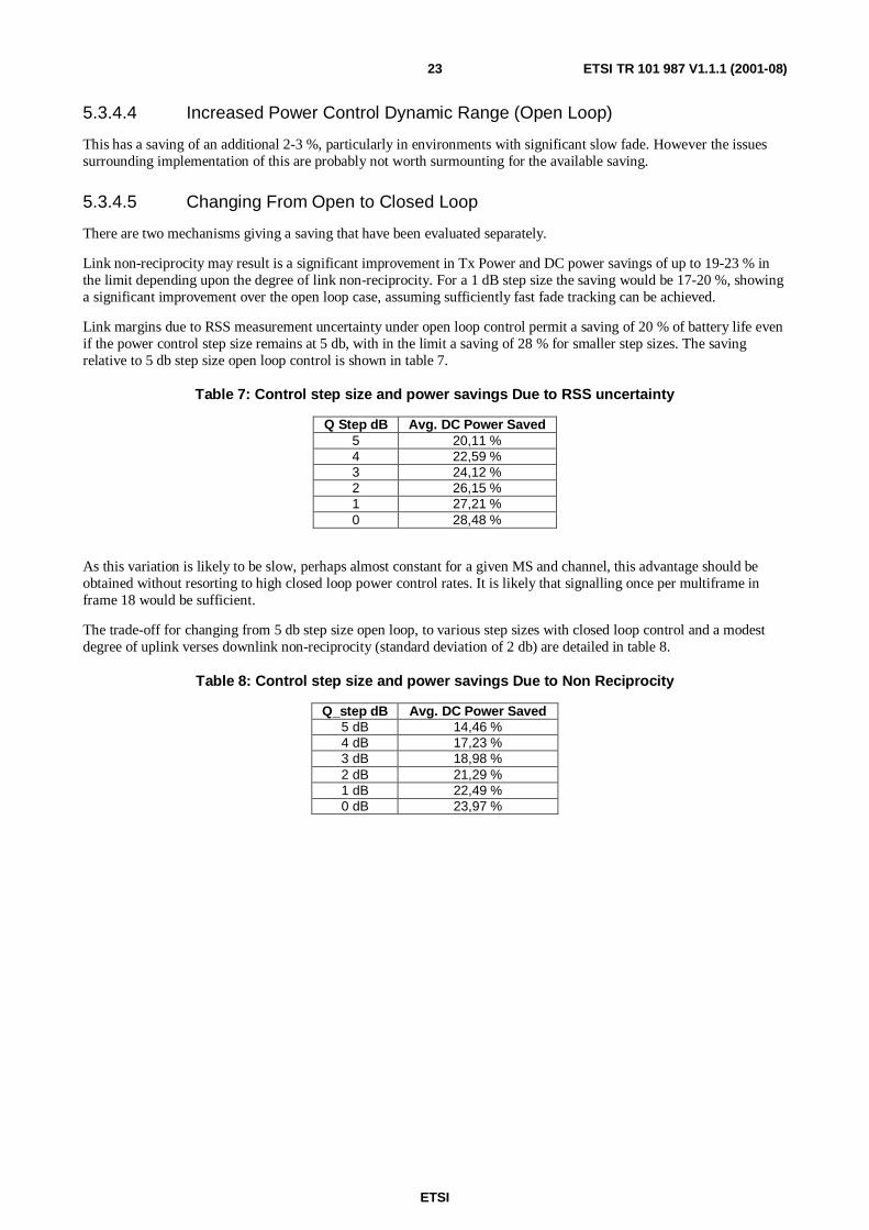
Link margins due to RSS measurement uncertainty under open loop control permit a saving of 20 % of battery life evenif the power control step size remains at 5 db, with in the limit a saving of 28 % for smaller step sizes. The savingrelative to 5 db step size open loop control is shown in table 7.
Table 7: Control step size and power savings Due to RSS uncertainty
Q Step dB Avg. DC Power Saved5 20,11 %4 22,59 %3 24,12 %2 26,15 %1 27,21 %0 28,48 %
As this variation is likely to be slow, perhaps almost constant for a given MS and channel, this advantage should beobtained without resorting to high closed loop power control rates. It is likely that signalling once per multiframe inframe 18 would be sufficient.
The trade-off for changing from 5 db step size open loop, to various step sizes with closed loop control and a modestdegree of uplink verses downlink non-reciprocity (standard deviation of 2 db) are detailed in table 8.
Table 8: Control step size and power savings Due to Non Reciprocity
Q_step dB Avg. DC Power Saved5 dB 14,46 %4 dB 17,23 %3 dB 18,98 %2 dB 21,29 %1 dB 22,49 %0 dB 23,97 %
ETSI
ETSI TR 101 987 V1.1.1 (2001-08)24
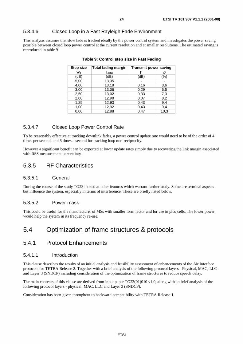
5.3.4.6 Closed Loop in a Fast Rayleigh Fade Environment
This analysis assumes that slow fade is tracked ideally by the power control system and investigates the power savingpossible between closed loop power control at the current resolution and at smaller resolutions. The estimated saving isreproduced in table 9.
Table 9: Control step size in Fast Fading
Step size Total fading margin Transmit power savingw0 Ltotal ΓΓΓΓ αααα
(dB) (dB) (dB) (%)5,00 13,35 - -4,00 13,19 0,16 3,63,00 13,06 0,29 6,52,50 13,02 0,33 7,32,00 12,98 0,37 8,21,25 12,93 0,43 9,41,00 12,92 0,43 9,40,00 12,88 0,47 10,3
5.3.4.7 Closed Loop Power Control Rate
To be reasonably effective at tracking downlink fades, a power control update rate would need to be of the order of 4times per second, and 8 times a second for tracking loop non-reciprocity.
However a significant benefit can be expected at lower update rates simply due to recovering the link margin associatedwith RSS measurement uncertainty.
5.3.5 RF Characteristics
5.3.5.1 General
During the course of the study TG23 looked at other features which warrant further study. Some are terminal aspectsbut influence the system, especially in terms of interference. These are briefly listed below.
5.3.5.2 Power mask
This could be useful for the manufacturer of MSs with smaller form factor and for use in pico cells. The lower powerwould help the system in its frequency re-use.
5.4 Optimization of frame structures & protocols
5.4.1 Protocol Enhancements
5.4.1.1 Introduction
This clause describes the results of an initial analysis and feasibility assessment of enhancements of the Air Interfaceprotocols for TETRA Release 2. Together with a brief analysis of the following protocol layers - Physical, MAC, LLCand Layer 3 (SNDCP) including consideration of the optimization of frame structures to reduce speech delay.
The main contents of this clause are derived from input paper TG23(01)010 v1.0, along with an brief analysis of thefollowing protocol layers - physical, MAC, LLC and Layer 3 (SNDCP).
Consideration has been given throughout to backward compatibility with TETRA Release 1.
ETSI
ETSI TR 101 987 V1.1.1 (2001-08)25
5.4.1.2 The Physical layer
In order to ensure TETRA Release 1 compatibility the physical layer should remain unchanged in TETRA Release 2 toallow all TETRA mobiles and Base Stations to access the control channels. The Control uplink Burst (CB) and NormalUplink Burst (NUB) should continue to be supported to ensure that a TETRA Release 1 MS can work with a TETRARelease 2 SwMI and a TETRA Release 2 MS can work with a TETRA Release 1 SwMI. - the framing and structure ofthese bursts are best left unchanged. Although differences in the structure and format of the bursts can be defined bytraining sequences, calls involving a mixture of TETRA Release 1 and TETRA Release 2 mobiles must be considered.In group calls involving both TETRA Release 1 and TETRA Release 2 mobiles, changes to the physical layer willalmost certainly introduce compatibility problems.
5.4.1.3 The MAC layer
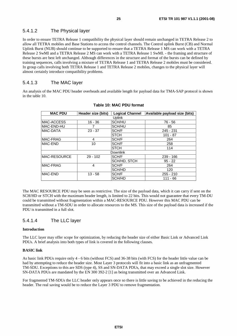
An analysis of the MAC PDU header overheads and available length for payload data for TMA-SAP protocol is shownin the table 10.
Table 10: MAC PDU format
MAC PDU Header size (bits) Logical Channel Available payload size (bits)Uplink
MAC-ACCESS 16 - 36 SCH/HU 76 - 56MAC-END-HU 7 SCH/HU 85
SCH/F 245 - 231MAC-DATA 23 - 37STCH 101 - 87
MAC-FRAG 4 SCH/F 264SCH/F 258MAC-END 10STCH 114
DownlinkSCH/F 239 - 166MAC-RESOURCE 29 - 102SCH/HD, STCH 95 - 22SCH/F 264MAC-FRAG 4SCH/HD 120SCH/F 255 - 210MAC-END 13 - 58SCH/HD 111 - 66
The MAC RESOURCE PDU may be seen as restrictive. The size of the payload data, which it can carry if sent on theSCH/HD or STCH with the maximum header length, is limited to 22 bits. This would not guarantee that every TM-DUcould be transmitted without fragmentation within a MAC-RESOURCE PDU. However this MAC PDU can betransmitted without a TM-SDU in order to allocate resources to the MS. This size of the payload data is increased if thePDU is transmitted in a full slot.
5.4.1.4 The LLC layer
Introduction
The LLC layer may offer scope for optimization, by reducing the header size of either Basic Link or Advanced LinkPDUs. A brief analysis into both types of link is covered in the following clauses.
BASIC link
As basic link PDUs require only 4 - 6 bits (without FCS) and 36-38 bits (with FCS) for the header little value can behad by attempting to reduce the header size. Most Layer 3 protocols will fit into a basic link as an unfragmentedTM-SDU. Exceptions to this are SDS (type 4), SS and SN-DATA PDUs, that may exceed a single slot size. HoweverSN-DATA PDUs are mandated by the EN 300 392-2 [1] as being transmitted over an Advanced Link.
For fragmented TM-SDUs the LLC header only appears once so there is little saving to be achieved in the reducing theheader. The real saving would be to reduce the Layer 3 PDU to remove fragmentation.
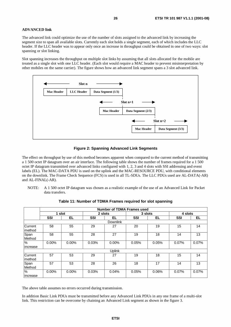
ETSI
ETSI TR 101 987 V1.1.1 (2001-08)26
ADVANCED link
The advanced link could optimize the use of the number of slots assigned to the advanced link by increasing thesegment size to span all available slots. Currently each slot holds a single segment, each of which includes the LLCheader. If the LLC header was to appear only once an increase in throughput could be obtained in one of two ways: slotspanning or slot linking.
Slot spanning increases the throughput on multiple slot links by assuming that all slots allocated for the mobile aretreated as a single slot with one LLC header. (Each slot would require a MAC header to prevent misinterpretation byother mobiles on the same carrier). The figure shows how an advanced link segment spans a 3 slot advanced link.
Mac Header LLC Header Data Segment (1/3)
Slot n
Data Segment (2/3)Mac Header
Slot n+1
Data Segment (3/3)Mac Header
Slot n+2
Figure 2: Spanning Advanced Link Segments
The effect on throughput by use of this method becomes apparent when compared to the current method of transmittinga 1 500 octet IP datagram over an air interface. The following table shows the number of frames required for a 1 500octet IP datagram transmitted over advanced links configured with 1, 2, 3 and 4 slots with SSI addressing and eventlabels (EL). The MAC-DATA PDU is used on the uplink and the MAC-RESOURCE PDU, with conditional elementson the downlink. The Frame Check Sequence (FCS) is used in all TL-SDUs. The LLC PDUs used are AL-DATA(-AR)and AL-FINAL(-AR).
NOTE: A 1 500 octet IP datagram was chosen as a realistic example of the use of an Advanced Link for Packetdata transfers.
Table 11: Number of TDMA Frames required for slot spanning
Number of TDMA Frames used1 slot 2 slots 3 slots 4 slots
SSI EL SSI EL SSI EL SSI ELDownlink
Currentmethod
58 55 29 27 20 19 15 14
SpanMethod
58 55 28 27 19 18 14 13
%increase
0.00% 0.00% 0.03% 0.00% 0.05% 0.05% 0.07% 0.07%
UplinkCurrentmethod
57 53 29 27 19 18 15 14
SpanMethod
57 53 28 26 18 17 14 13
%increase
0.00% 0.00% 0.03% 0.04% 0.05% 0.06% 0.07% 0.07%
The above table assumes no errors occurred during transmission.
In addition Basic Link PDUs must be transmitted before any Advanced Link PDUs in any one frame of a multi-slotlink. This restriction can be overcome by chaining an Advanced Link segment as shown in the figure 3.
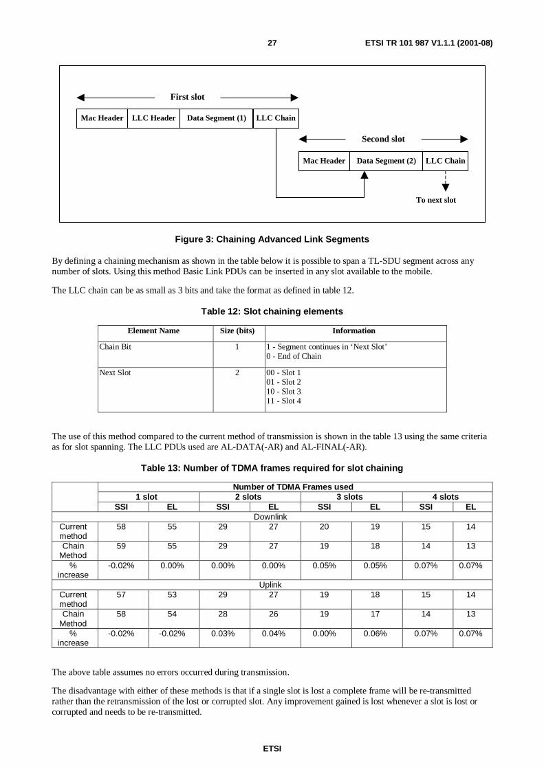
ETSI
ETSI TR 101 987 V1.1.1 (2001-08)27
To next slot
Mac Header LLC Header Data Segment (1) LLC Chain
Mac Header Data Segment (2) LLC Chain
First slot
Second slot
Figure 3: Chaining Advanced Link Segments
By defining a chaining mechanism as shown in the table below it is possible to span a TL-SDU segment across anynumber of slots. Using this method Basic Link PDUs can be inserted in any slot available to the mobile.
The LLC chain can be as small as 3 bits and take the format as defined in table 12.
Table 12: Slot chaining elements
Element Name Size (bits) Information
Chain Bit 1 1 - Segment continues in ‘Next Slot’0 - End of Chain
Next Slot 2 00 - Slot 101 - Slot 210 - Slot 311 - Slot 4
The use of this method compared to the current method of transmission is shown in the table 13 using the same criteriaas for slot spanning. The LLC PDUs used are AL-DATA(-AR) and AL-FINAL(-AR).
Table 13: Number of TDMA frames required for slot chaining
Number of TDMA Frames used1 slot 2 slots 3 slots 4 slots
SSI EL SSI EL SSI EL SSI ELDownlink
Currentmethod
58 55 29 27 20 19 15 14
ChainMethod
59 55 29 27 19 18 14 13
%increase
-0.02% 0.00% 0.00% 0.00% 0.05% 0.05% 0.07% 0.07%
UplinkCurrentmethod
57 53 29 27 19 18 15 14
ChainMethod
58 54 28 26 19 17 14 13
%increase
-0.02% -0.02% 0.03% 0.04% 0.00% 0.06% 0.07% 0.07%
The above table assumes no errors occurred during transmission.
The disadvantage with either of these methods is that if a single slot is lost a complete frame will be re-transmittedrather than the retransmission of the lost or corrupted slot. Any improvement gained is lost whenever a slot is lost orcorrupted and needs to be re-transmitted.
ETSI
ETSI TR 101 987 V1.1.1 (2001-08)28
5.4.1.5 Layer 3 protocols
Introduction
Examination of the lower levels of the protocol stack offers very little scope for enhancement. However within the layer3 protocols there is a possibility that the size of some PDUs may lead to excessive fragmentation. This is covered in thefollowing clauses.
Transmission of Large PDUs
As mentioned above the following PDUs may not fit into a single slot:
• SDS (type 4)
• Supplementary Services PDUs
• SN-DATA PDU
Of the above, SN-DATA PDUs are transmitted on an Advanced Link, which through segmentation provides a moreefficient transport layer than fragmentation on a Basic Link. SDS type 4 could also be transmitted on an Advanced Linkif supported by the MS.
Within the SNDCP protocol the following PDUs will be fragmented:
• SN-ACTIVATE PDP CONTEXT DEMAND
• SN-ACTIVATE PDP CONTEXT ACCEPT
The SN-ACTIVATE PDP CONTEXT DEMAND PDU will be typically 98 octets in length if the following options arerequested for the PDP context:
• dynamic IP address allocation,
• Header compression (not Van Jacobson),
• Access Point Name index,
• V.42bis compression? and
• Authentication using CHAP.
This is subject to an increase in size of up to 6 octets if Van Jacobson header compression and additional datacompression algorithms are specified. This will require at least 4 fragments to be transmitted on the uplink.
The SN-ACTIVATE PDP CONTEXT ACCEPT PDU can vary between 43 to 76 octets in length depending on theconfiguration requested by the MS for the PDP Context as shown in the table 14.
ETSI
ETSI TR 101 987 V1.1.1 (2001-08)29
Table 14: SN-ACTIVATE PDP CONTEXT ACCEPT PDU sizes
Number ofOctets
Configuration Options Number ofFragments
43 Static or dynamic address allocation,Header compression (not Van Jacobson),Access Point Name index not included,V.42bis compression andProtocol configuration of primary and secondary DNS serveraddresses.This is subject to an increase in size of up to 8 octets if VanJacobson header compression, Access Point Name index andadditional data compression algorithms are specified
2
48 Mobile IPv4 address allocation,Header compression (not Van Jacobson),Access Point Name index not included,V.42bis compression andProtocol configuration of primary and secondary DNS serveraddresses.This is subject to an increase in size of up to 8 octets if VanJacobson header compression, Access Point Name index andadditional data compression algorithms are specified
2 - 3
76 IPv6 address allocation,Header compression (not Van Jacobson),Access Point Name index,V.42bis compression andProtocol configuration of primary and secondary DNS serveraddresses.This is subject to an increase in size of up to 7 octets if AccessPoint Name index and additional data compression algorithmsare specified
3
Two courses of action are available:
1) If the MS or SwMI detects that a layer 3 PDU is likely to suffer from excessive fragmentation then therecommendation in the Air Interface Standard clause 24.4.2.1 [1] should be followed. The PDU should betransmitted on an existing Advanced Link or an Advanced Link should be created. This requires no change to thestandard [1] but is an implementation issue.
2) Specifically in the case of the SN-ACTIVATE PDP CONTEXT DEMAND and SN-ACTIVATE PDPCONTEXT ACCEPT PDUs the ‘protocol configuration’ element could be sent in a separate SN-CONTEXTCONFIGURE PDU. This PDU can be used to transfer configuration data on the uplink and downlink. ThisSN-ACTIVATE PDP CONTEXT DEMAND and SN-ACTIVATE PDP CONTEXT ACCEPT PDUs are used tocreate and authenticate the context whilst the SN-CONTEXT CONFIGURE PDUs are used to negotiate thecompression, protocol and other configurable elements.
Reduction in On-Air signalling
Whilst the Air Interface Standard [1] defines the protocols to be used, further work is required to use the protocolefficiently. For example, a PDCH (Packet Data CHannel) can be used to both exchange Packet Data and to performCC.CMCE and MM signalling. This is using the PDCH in its capacity as an ASCCH (Assigned Secondary ControlCHannel). However these issues are currently addressed at the TETRA IOP MoU. Changes are often identified withinthis forum and passed to the relevant TETRA Working Group for further discussion and possible inclusion into theappropriate TETRA standard.
5.4.2 Reduced Speech Delay
In order to reduce the speech delay on the Air Interface a TCH could use all 18 frames in a multi-frame to transmitspeech. However frame 18 is currently used to broadcast network information on the BNCH, for synchronization on theBSCH - downlink - and linearization on the CLCH - uplink, In addition, Frame 18 is also for call maintenance on boththe uplink and downlink. Although the speech delay can be reduced by this method consideration must be given to thebroadcast of the BNCH and BSCH on the downlink and the CLCH on the uplink, call maintenance and maintainingcompatibility with TETRA Release 1 mobiles and SwMIs.
ETSI
ETSI TR 101 987 V1.1.1 (2001-08)30
5.4.3 Recommendations
The Physical Layer
In order to maintain compatibility between TETRA Release 1 and TETRA Release 2 no changes are proposed to thephysical layer of the Air Interface.
The MAC Layer
No enhancement changes to the MAC layer are proposed.
The LLC Layer
Basic Link
No enhancement to the Basic Link protocol is proposed.
Advanced Link
No enhancement to the Advanced Link protocol is proposed.
Layer 3 protocols
Transmission of Large PDUs
Due to the potentially large size of some of the SNDCP protocol PDUs it is proposed that an input paper be submittedto WG3 for discussion on how the LLC may implement an advanced link for the purpose of transmitting large PDUs.
It is also proposed an input paper specifying how protocol configuration may be implemented in smaller, unfragmentedPDUs for TETRA Release 2 systems be submitted to WG3.
Reduction in On-Air signalling
It is recommended that the current feedback from the TETRA IOP MoU continues to be used as the vehicle for ensuringoptimization of the Air Interface protocols.
Reduced Speech Delay
No feasible enhancements have been identified for speech delay reduction.
5.5 User requirements implementation issues
5.5.1 General
This clause describes results of analysis and feasibility assessment of the enhancements of extended range and provisionof location information.
5.5.2 TETRA LCS (Location Service)
5.5.2.1 Background
Location services are starting to emerge in cellular networks and cellular positioning is gaining increasing publicityboth in media and telecommunications forums. The drivers of the positioning functionality have been both regulativeand commercial.
On the regulatory side the process was started in the USA, where the FCC required that 911 calls from cellular phonesshall be located after 1st of October 2001. The accuracy and reliability requirements are:
• for network based solutions, 100 m for 67 % of calls, 300 m for 95 % of calls;
• for handset based solutions, 50 m for 67 % of calls, 150 m for 95 % of calls.
ETSI
ETSI TR 101 987 V1.1.1 (2001-08)31
A similar requirement to the FCC 911 is being considered by the EU called E112. To address this and otherrequirements for terminal location, a group of interested parties has been formed called the Location InteroperabilityForum. The purpose is to define, develop and promote through the global standards bodies and specificationorganizations - a common and ubiquitous location services solution. Such a solution is intended to:
• define a simple and secure access method that allows user appliances and Internet applications to access locationinformation from the wireless network irrespective of their underlying air interface technologies and positioningmethods.
• promote a family of standards-based location determination methods and their supporting architectures that arebased on Cell Sector-ID, Cell-ID and Timing Advance, E-OTD (GSM), AFLT (IS-95) and MS-Based AssistedGPS.
• establish a framework for contributing to the global standards bodies and specification organizations to definecommon methods and procedures for the testing and verification of the LIF recommended access methods andpositioning technologies.
The demands for the positioning are not only driven by regulation, but there is also increased pressure from the market.Numerous commercial and non-commercial applications are closely following the progress on standardization andtechnology. To be fully competitive with the other cellular systems TETRA has to be able to provide positioningfunctionality. The overall system to provide the information could be called TETRA LCS, TETRA Location Service.
5.5.2.2 Location dependent services (LDS)
Providing geographical co-ordinates does not have much value as such, but when related to some location dependentservice (LDS) the information will have greater importance. The situation is totally different with the traditional GPSwhere positional co-ordinates, speed and heading are the main information that is utilized. In a telecommunicationenvironment, tracking a real-time position for navigational purpose is not considered feasible.
There are many different categories of LDSs such as emergency call locationing, information services, networkadministration, fraud control and billing control. To support all of these purposes it is beneficial if the system is able toprovide an open interface for application developers. In that case there will be interest in developing applications to takethe full advantage of the system.
For the TETRA community LCS will provide effective means to compete with other systems. Plenty of applications canbe run when location information will be available. The public safety segment, with its responsibility for emergencyservices, will have increased value from the use of location information. For professional TETRA operators LCS willenable great possibilities in numerous areas. GPS is already being used in fleet management systems where TETRA iscurrently used only as a bearer for the transmission of positional co-ordinates. LCS could provide an integrated andmore flexible solution.
5.5.2.3 Location issues related to TETRA
When considering implementation of location services to TETRA network there are some important aspects that mustbe considered. Firstly the viable location method(s) that could be implemented in the TETRA system have to beinvestigated. A second issue of importance is the additional signalling needed for those systems.
At the moment there are numerous location methods that have been investigated for other cellular systems. Thosemethods can be divided roughly into two categories: cellular network based methods and GPS-based methods. Inconsiderations each method has to be balanced taking the received performance and implementation costs into account.
It is obvious that the location method will require additional signalling within TETRA network. New messages willinclude at least position request and position response.
When considering formats for the messages the following has to be considered:
• Is there a need to specify TETRA-specific formats?
• Is there a possibility to take the advantage of using the formats specified for other systems?
If TETRA specific formats are seen as important, then the need has to be well justified since the workload tostandardize the formats will be significant. Additionally with TETRA-specific messages there is a great risk to lose theinteroperability with other systems and networks.
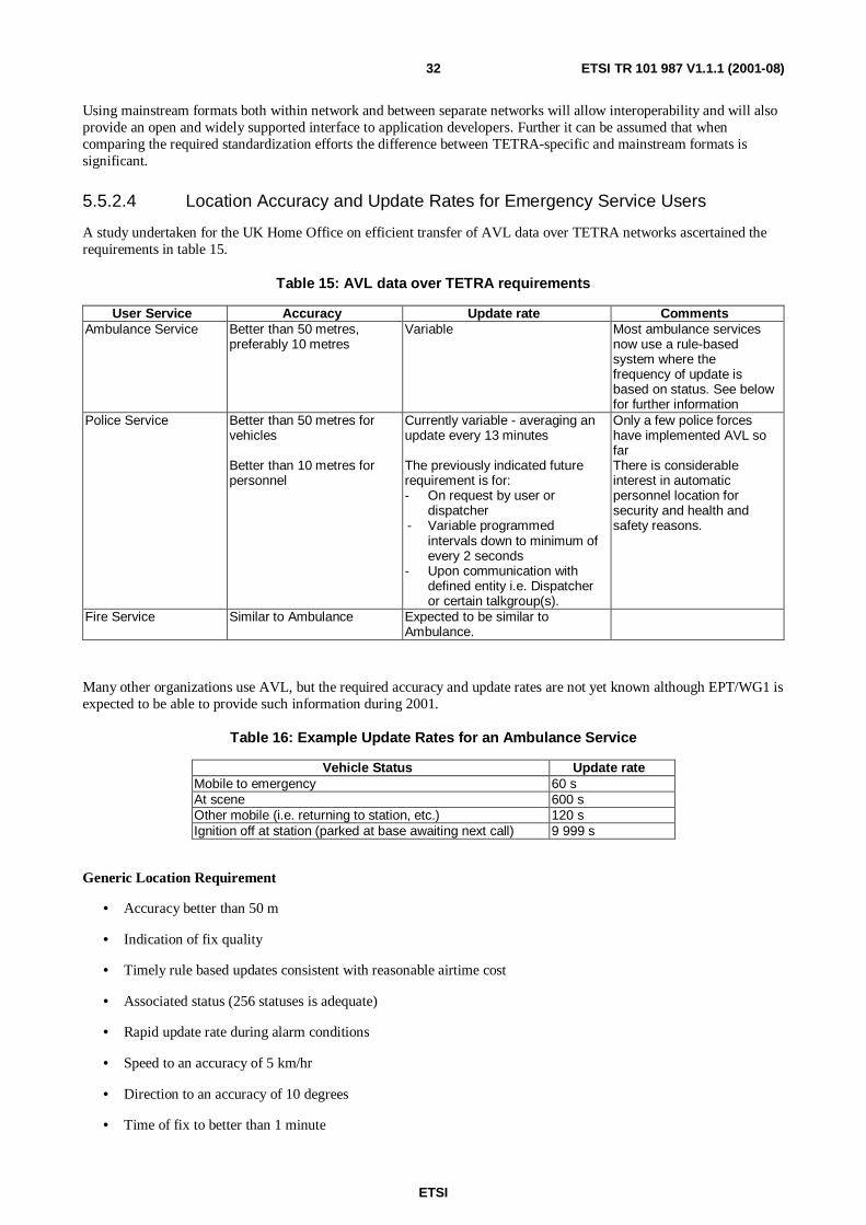
ETSI
ETSI TR 101 987 V1.1.1 (2001-08)32
Using mainstream formats both within network and between separate networks will allow interoperability and will alsoprovide an open and widely supported interface to application developers. Further it can be assumed that whencomparing the required standardization efforts the difference between TETRA-specific and mainstream formats issignificant.
5.5.2.4 Location Accuracy and Update Rates for Emergency Service Users
A study undertaken for the UK Home Office on efficient transfer of AVL data over TETRA networks ascertained therequirements in table 15.
Table 15: AVL data over TETRA requirements
User Service Accuracy Update rate CommentsAmbulance Service Better than 50 metres,
preferably 10 metresVariable Most ambulance services
now use a rule-basedsystem where thefrequency of update isbased on status. See belowfor further information
Police Service Better than 50 metres forvehicles
Better than 10 metres forpersonnel
Currently variable - averaging anupdate every 13 minutes
The previously indicated futurerequirement is for:- On request by user or
dispatcher- Variable programmed
intervals down to minimum ofevery 2 seconds
- Upon communication withdefined entity i.e. Dispatcheror certain talkgroup(s).
Only a few police forceshave implemented AVL sofarThere is considerableinterest in automaticpersonnel location forsecurity and health andsafety reasons.
Fire Service Similar to Ambulance Expected to be similar toAmbulance.
Many other organizations use AVL, but the required accuracy and update rates are not yet known although EPT/WG1 isexpected to be able to provide such information during 2001.
Table 16: Example Update Rates for an Ambulance Service
Vehicle Status Update rateMobile to emergency 60 sAt scene 600 sOther mobile (i.e. returning to station, etc.) 120 sIgnition off at station (parked at base awaiting next call) 9 999 s
Generic Location Requirement
• Accuracy better than 50 m
• Indication of fix quality
• Timely rule based updates consistent with reasonable airtime cost
• Associated status (256 statuses is adequate)
• Rapid update rate during alarm conditions
• Speed to an accuracy of 5 km/hr
• Direction to an accuracy of 10 degrees
• Time of fix to better than 1 minute
ETSI
ETSI TR 101 987 V1.1.1 (2001-08)33
Rule Based Systems
Most AVL designers are now using rules based update systems. This allows the mobile unit to decide when to transmitan AVL report, obviating the need for polling. The rules are programmed in when the unit is installed and can bemodified by commands sent over the air from control.
A typical set of rules is as follows:
• Time since last report generated.
• Distance travelled since last report.
• Response to a poll command from the communications centre.
• Manually generated report (from the user/equipment).
• Whether the vehicle has stopped/started moving.
• Reaching a reporting point (waypoint).
• Change of status of vehicle crew (entered through the data terminal).
• Operation of panic button or switch input.
• Change of status or other input signal.
• Loss or restoration of GPS coverage.
• Restoration of coverage of radio network.
• Change of AVL operating profile.
The main disadvantage of a rule-based system is that the receiving application can never be sure that the locationinformation is up-to-date unless a method of acknowledgement is used for all messages.
5.5.2.5 Location methods
The key question of the TETRA location service is the method to be used. There are various methods that have beendiscussed within telecommunication arena. Since each of these methods will have both pros and cons, the methods withtheir key characteristics are presented here.
Cell ID
The simplest method for estimating location in a network is to utilize the data used by radio resource management, suchas the identification of the serving base station - Cell ID. The accuracy will be the area of a base station coverage, i.e.the MS can be positioned to be within boundary of a certain cell which means that the accuracy is dependent on the cellsize. At the moment the cell identity is not necessarily known by the SwMI, but it is estimated that with moderateadditional work, the information can be obtained.
Received Signal Strength (RSS)
In the Received Signal Strength method MSs measure the received signal levels of serving and neighbouring basestations. The received signal strength is a function of BS power, distance and propagation conditions. Distance to amobile station can be estimated if BS Power level and propagation conditions are known. The position of an MS can beestimated when the measurement information of a few base stations are combined. Since the end result is highly relatedto propagation conditions, the accuracy will have great variations but may be a viable enhancement to increase theaccuracy of the Cell ID method. Implementation of methods based on received signal strengths requires co-ordinationand signalling between base stations.
ETSI
ETSI TR 101 987 V1.1.1 (2001-08)34
Timing Advance/Round Trip Time (TA / RTT)
For GSM a Timing Advance-based method has been considered. In GSM, with the aid of timing advance information adistance with an accuracy of 550 m could be estimated. However to locate also the direction would require TAinformation from at least of three serving base stations which is not feasible since there is only one serving base stationat a time. The idea of standardizing timing advances to several base stations was never adopted in GSM. In TETRAthere is no timing advance information.
RTT, Round Trip Time, also referred as Round Trip Delay (RTD), has been suggested for use with UMTS. RTT inUMTS has been claimed to have better accuracy than the TA method of GSM. In the RTT method the propagation timeforth and back from BS is measured and the estimate of distance is calculated. This method requires tightsynchronization between BS and MS.
For TETRA, both TA and RTT methods are limited to a location accuracy of 1-2 km due to the TETRA symbol lengthand MS/BS synchronization requirements (see EN 300-392-2, clause 7.6 [1]).
Angle of Arrival (AoA)
In the Angle of Arrival method the signal transmitted by the MS is measured by base stations. By using smart antennasthe direction of an incident wave can be estimated. To estimate the position requires at least two AoA measurementsfrom separate sites. Implementing AoA method requires co-ordination between base stations, which generatesadditional signalling load in the network. Both software and hardware changes are needed in the network. AoA does notneed any changes to the MS.
As a method AoA is relatively accurate in good conditions, but reflections and Non Line of Sight will cause significantdecrease in performance.
Time of Arrival (ToA)
The Time of Arrival method is based on measuring the arrival times of MS signals at different base stations in thenetwork. ToA requires a common and accurate timing reference and also co-ordination between measurementequipment. For an MS no changes are required. Since TETRA does not offer any common and accurate time base theimplementation would require additional timing references and synchronization mechanisms. Also control logic wouldneed to be implemented to take care of the measurement triggering and provision of results.
Since a number of base stations would be measuring the same burst from the MS and the location calculated usingtriangulation by computing the time differences, the location accuracy would depend on the accuracy of the timingsynchronization between the measuring base stations (typically synchronized by GPS), and the base stations timingresolution.
NOTE: For GSM a typical accuracy has been estimated at between 50-150 m - see Ericsson Review No. 4, 1999.
Observed Time Difference (OTD)
Observed Time Difference is a method where the MS measures the time differences of signals received from separatebase stations. To work accurately this method requires either tight synchronization between base stations or BSsynchronization can be measured with special receivers located at known positions. In GSM system these receivers arecalled E-OTD LMUs. By combining results from the MS and the E-OTD-LMU with BS co-ordinates the location of theMS can be computed. Implementing OTD for TETRA would require major changes to the network and also quitesignificant software changes to the MS.
The location accuracy would depend on the accuracy with which the MS can measure the time differences (the currentrequirement being to ensure a maximum synchronization error of ¼ symbol - see EN 300-392-2, clause 7.6 [1]).
GPS
GPS methods are based on positioning a subscriber with the additional system known as the Global Positioning System.
ETSI
ETSI TR 101 987 V1.1.1 (2001-08)35
Stand-alone GPS
Those who have used traditional Stand-alone GPS receivers may have noticed the weak points of it. When initializingthe equipment, the user is asked to input an estimate of their location and time information. Typically this information isinputted as: "I am in Belgium and the time is quarter past eleven (checked from wrist watch)." The procedure starts withchecking from the almanac the possible satellites that could be available in Line Of Sight. When satellites are found thereceiver synchronizes itself to the direct sequence spread spectrum signal sent by the satellites. The receiver has to beable to decode the coarse acquisition information from the L1 carrier in order to have the first fix of location.
Since a low cost GPS receiver does not have a very accurate clock, the initial frequency error between the localoscillator and the satellite signals can be relatively large. A GPS receiver must step its time base systematically andattempt blind synchronization, before the local clock is tuned to the correct value. In addition, the receiver must listen tothe GPS signal for a while before it can decode all needed information. Thus, a relatively long time - up to two minutes- is needed in a traditional GPS receiver after power on until the first location fix. If there is no prior information aboutthe coarse position, time and date needed by the GPS receiver to compute which satellites to search, the start-up cantake hours.
This lengthy process may not be feasible for a handheld MS where power consumption and operating times are critical.If provision of location is required with an emergency call, the process would be expected to be rapid. To overcomethese deficiencies an Assisted-GPS has been developed. In the market there exists at least two type of assisted methods,Network Assisted - Mobile Based and Mobile Assisted - Network Based GPS.
Network Assisted - Mobile Based GPS
In mobile-based GPS, the receivers in fixed positions (at Base Station sites) measure GPS and other information all thetime. At appropriate and predefined intervals the network broadcasts point-to-point messages to MSs. This sentinformation is referred as assistance data. Assistance data includes parameters such as visible satellites at the moment,the ionospheric condition information, C/A code information, bad satellite IDs, etc.
The benefits of mobile-based GPS are related to response time and also to the required signal level. Since the receiveralready has all the required information related to satellites used in location measurements, the receiver can start tocalculate the position without the lengthy synchronization process. In addition, with assistance data, the GPS receiverobtains a significant gain benefit that can be used in areas where propagation conditions are weak, e.g. urban areas andinside buildings. The gain benefit is received due the fact that the S/N required for measuring the time estimates is farless than the S/N required for decoding the data transmitted by the satellite.
Mobile Assisted - Network Based GPS
The mobile-based GPS method does not significantly affect the complexity of the GPS receiver. In network based GPS,part of the functions of the GPS receiver are moved to the cellular network. The basic solution contains RF receivers,code generators and correlators to measure satellite timing. The cellular network broadcasts assistance data, whichcontains a list of satellites, their expected carrier Doppler shifts and code search phases. The timing measurement resultsare sent to the location server on the network, which performs the location calculation.
The drawback of the network-based method when compared to network assisted one is the limited capacity of thesystem. In a case where the location has to be updated frequently the signalling load becomes significant. The greatestadvantage of the network-based method over the mobile-based method has been the simplicity of radio parts that haveto be implemented into an MS. However the rapid development and the achievements on the integration level of GPScircuit technology have shifted the advantage to the mobile-based method. The savings, both in the required PCB areaand in costs, are not relevant anymore.
5.5.2.6 Summary
In the telecommunication standardization arena there are numerous different methods for location that have been dealtwith. When making a decision on the method that should be accommodated in TETRA, following issues must beaddressed:
• Accuracy requirement
• Implementation penalty of the Network
• Implementation penalty of the MS
ETSI
ETSI TR 101 987 V1.1.1 (2001-08)36
Cell ID would be the simplest method to implement but its accuracy obviously depends on the size of the cell in whichthe MS is located. However, in urban areas where a greater accuracy may be required the cell size is likely to be smallerand hence implicitly provides the greater required accuracy.
For timing methods that depend upon tight synchronization between the MS and BS, the symbol duration is significantas the permissible synchronization error (which directly contributes to the RTT estimation error) is proportional to thesymbol length. Tetra's relatively long symbol length, compared to the channel bandwidth, can cause a larger RTT errorthan GSM, leading to poorer location accuracy. Methods that rely on measuring time differences of observedtransmissions are generally limited to the measuring resolution of the MS or BS element. In many cases the finalaccuracy (e.g. 1-2 km) of methods that are based on time information may not be significantly better than that of CellID.
The Angle of Arrival measurement could give relatively accurate results, but only in good conditions. In environmentswhere reflections occur, the accuracy also suffers and the AoA method requires major changes to the network side suchas co-ordination between base stations and smart antennas that would add significant costs to operators.
One of the big weakness of timing-based triangulation techniques is that for reasonable accuracy they rely on the MSbeing able to receive, or be received by, at least three base stations. Unless the network is specifically designed withadditional base stations the probability of this being achieved will depend upon the current location of the MS as well asthe network coverage planning criteria.
GPS based methods can provide the best location accuracy (10-50 m) but perform weakly in urban environment and inbuildings. The lengthy start-up process for stand-alone GPS may be mitigated by implementation of an assistedmethod - of which the network assisted - mobile-based method seems to be most attractive.
5.5.3 Extended Range Capability
5.5.3.1 General
TETRA Release 1 has a limitation in range due to timing issues. For trunked mode the range is limited to about 58 kmand for direct mode the limitation is even to be less.
In some situations there is an operational need for an extended range. Requirement scenarios include aeronautical andmaritime use, "linear cells" (e.g. pipelines, railways) and large rural cells (large low-traffic areas).
For land-based MSs a modified Hata propagation model should be used - see ERC report 68 "Monte Carlo RadioSimulation Methodology" (to be found at http://www.ero.dk/).
5.5.3.2 Aeronautical
A typical situation for a longer range is aeronautical use over land or sea. In this situation the aeronautical mobile wantsto have contact with other users on land.
Propagation studies show that at 400 MHz a range of 200 km is feasible (based on free space path loss which appliesinstead of the modified Hata model). Such a range would, in fact, fulfil an operational need to have communicationsover the whole North Sea.To minimize the number of frequencies needed for aeronautical use there must be efficient use of the radio carriers. It isexpected that up to 3 independent user groups could be active in the same area in a long-range situation.The speed during flights is typical 200 to 400 km/h and the maximum speed of the commonly used aircraft is 500 km/h.In normal long-range situations (with only aircraft involved) all TMO facilities are required. A terminal should be ableto roam between long-range cells and normal range cells. The users should not notice a difference between long rangeand normal range cells.
Characteristics
Cell shape circularMaximum BS-MS distance 200 kmMS maximum speed 500 km/h (fixed wing aircraft)Propagation environment MaritimeDistribution of subscribers UniformTypes of MS MobileAverage density Very lowMarket requirement A small but important number of safety users in littoral countries
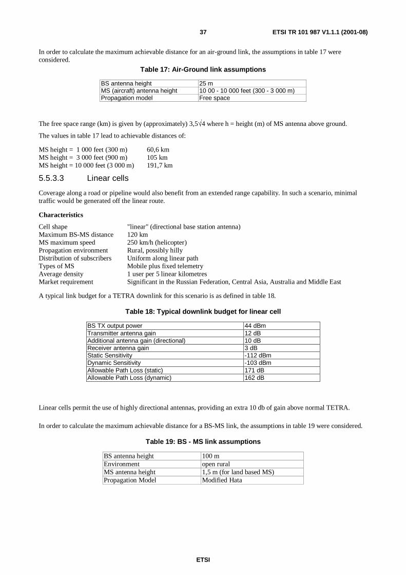
ETSI
ETSI TR 101 987 V1.1.1 (2001-08)37
In order to calculate the maximum achievable distance for an air-ground link, the assumptions in table 17 wereconsidered.
Table 17: Air-Ground link assumptions
BS antenna height 25 mMS (aircraft) antenna height 10 00 - 10 000 feet (300 - 3 000 m)Propagation model Free space
The free space range (km) is given by (approximately) 3,5√4 where h = height (m) of MS antenna above ground.
The values in table 17 lead to achievable distances of:
MS height = 1 000 feet (300 m) 60,6 kmMS height = 3 000 feet (900 m) 105 kmMS height = 10 000 feet (3 000 m) 191,7 km
5.5.3.3 Linear cells
Coverage along a road or pipeline would also benefit from an extended range capability. In such a scenario, minimaltraffic would be generated off the linear route.
Characteristics
Cell shape "linear" (directional base station antenna)Maximum BS-MS distance 120 kmMS maximum speed 250 km/h (helicopter)Propagation environment Rural, possibly hillyDistribution of subscribers Uniform along linear pathTypes of MS Mobile plus fixed telemetryAverage density 1 user per 5 linear kilometresMarket requirement Significant in the Russian Federation, Central Asia, Australia and Middle East
A typical link budget for a TETRA downlink for this scenario is as defined in table 18.
Table 18: Typical downlink budget for linear cell
BS TX output power 44 dBmTransmitter antenna gain 12 dBAdditional antenna gain (directional) 10 dBReceiver antenna gain 3 dBStatic Sensitivity -112 dBmDynamic Sensitivity -103 dBmAllowable Path Loss (static) 171 dBAllowable Path Loss (dynamic) 162 dB
Linear cells permit the use of highly directional antennas, providing an extra 10 db of gain above normal TETRA.
In order to calculate the maximum achievable distance for a BS-MS link, the assumptions in table 19 were considered.
Table 19: BS - MS link assumptions
BS antenna height 100 mEnvironment open ruralMS antenna height 1,5 m (for land based MS)Propagation Model Modified Hata
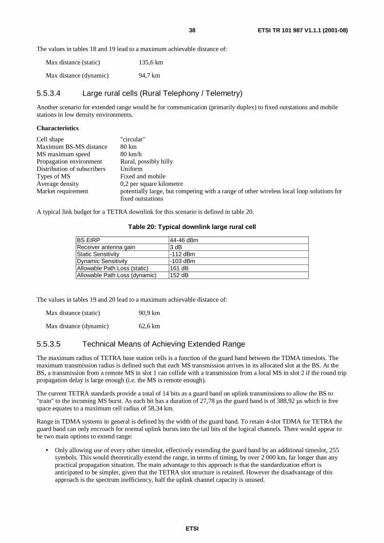
ETSI
ETSI TR 101 987 V1.1.1 (2001-08)38
The values in tables 18 and 19 lead to a maximum achievable distance of:
Max distance (static) 135,6 km
Max distance (dynamic) 94,7 km
5.5.3.4 Large rural cells (Rural Telephony / Telemetry)
Another scenario for extended range would be for communication (primarily duplex) to fixed outstations and mobilestations in low density environments.
Characteristics
Cell shape "circular"Maximum BS-MS distance 80 kmMS maximum speed 80 km/hPropagation environment Rural, possibly hillyDistribution of subscribers UniformTypes of MS Fixed and mobileAverage density 0,2 per square kilometreMarket requirement potentially large, but competing with a range of other wireless local loop solutions for
fixed outstations
A typical link budget for a TETRA downlink for this scenario is defined in table 20.
Table 20: Typical downlink large rural cell
BS EIRP 44-46 dBmReceiver antenna gain 3 dBStatic Sensitivity -112 dBmDynamic Sensitivity -103 dBmAllowable Path Loss (static) 161 dBAllowable Path Loss (dynamic) 152 dB
The values in tables 19 and 20 lead to a maximum achievable distance of:
Max distance (static) 90,9 km
Max distance (dynamic) 62,6 km
5.5.3.5 Technical Means of Achieving Extended Range
The maximum radius of TETRA base station cells is a function of the guard band between the TDMA timeslots. Themaximum transmission radius is defined such that each MS transmission arrives in its allocated slot at the BS. At theBS, a transmission from a remote MS in slot 1 can collide with a transmission from a local MS in slot 2 if the round trippropagation delay is large enough (i.e. the MS is remote enough).
The current TETRA standards provide a total of 14 bits as a guard band on uplink transmissions to allow the BS to"train" to the incoming MS burst. As each bit has a duration of 27,78 µs the guard band is of 388,92 µs which in freespace equates to a maximum cell radius of 58,34 km.
Range in TDMA systems in general is defined by the width of the guard band. To retain 4-slot TDMA for TETRA theguard band can only encroach for normal uplink bursts into the tail bits of the logical channels. There would appear tobe two main options to extend range:
• Only allowing use of every other timeslot, effectively extending the guard band by an additional timeslot, 255symbols. This would theoretically extend the range, in terms of timing, by over 2 000 km, far longer than anypractical propagation situation. The main advantage to this approach is that the standardization effort isanticipated to be simpler, given that the TETRA slot structure is retained. However the disadvantage of thisapproach is the spectrum inefficiency, half the uplink channel capacity is unused.
ETSI
ETSI TR 101 987 V1.1.1 (2001-08)39
• Use timing advance features as is used by the GSM family of standards. The introduction of timing advance toTETRA would be a radical departure from the current slot structure, The big disadvantage of this solution is thatit would require significant standardization and development effort on the air interface, impacting on terminalsand base stations. The advantage of this technique is that the spectrum efficiency is retained.
6 Feasible Options and Enhancements Phases
6.1 OPTIONS
6.1.1 Sub-area 1
Improved Handover
It is felt that handover could be improved by introducing the following options to the air interface standard(EN 300 392-2 [1]).
1) Define the RSS measurement methodology in the MS. This definition will impact on other areas of the presentdocument, notably MS open loop power control and MS location techniques.
2) Make recommendations (in an annexe) for the values of existing broadcast parameters for different cell types.
3) Add the colour code to the neighbour cell information element, clause 18.5.17.
4) Make the LA identifier mandatory in the U-Location Update Demand, clause 16.9.3.4.
5) Standardize the meaning of (at least "high") the Cell Service Level element of clause 18.5.5.
6) Change the closed loop power control descriptor (table 342) to include "near" uplink failure.
7) Change the closed loop power control descriptor (table 342) to include "near" maximum path delay.
8) Change the modelling in the downlink measurement to include a "near" downlink failure in clause 23.7.3.1.
9) Introduce a new PDU to indicate the uplink quality from the SwMI to the MS.
10)Introduce a new broadcast element to indicate the MS is to use external handover algorithms.
11)Introduce a new PDU to poll an MS for its downlink quality measurements.
12)Introduce a new PDU for an MS to report its downlink quality measurements as a response to the poll.
13 Introduce a new PDU to inform a MS to move to another cell.
14)Introduce a new PDU for a MS to respond to the instruction to move cell.
15)Introduce procedures for the use of the new PDUs in options 9 - 14. In particular such procedures must cater forhalf duplex calls (individual or group) and discontinuous transmission. In these cases the MS may not havetransmit permission or is not transmitting even though it is allowed to.
Hierarchical Cell Structures
The following options were identified as solutions to enable the implementation of Hierarchical Cell Structures:
1) Define the "Cell Priority" identifier. This will be used to label Microcells, and get them distinguished fromMacrocells. The values of the TEMPORARY_OFFSET and PENALTY_TIME parameters will be fixed in theMS. This is not a flexible solution but a quick win that enables the implementation of Hierarchical CellStructures.
ETSI
ETSI TR 101 987 V1.1.1 (2001-08)40
2) Add the TEMPORARY_OFFSET and PENALTY_TIME parameters to the broadcast message. This will addmore flexibility to the use of Hierarchical Cell Structures. Different cells can be treated differently according totheir size, their environment (urban, suburban or rural) and their level in the hierarchy (macro, micro or pico).Adding these parameters to the broadcast message requires significant change to the standard and thereforeshould be done in phase 2.
Frequency Hopping
Some work needs to be done to investigate the feasibility of implementing Frequency Hopping in TETRA. Two mainareas were identified, these are:
1) Investigate the complexity of the Linearization problem. This problem is a major challenge to theimplementation of Frequency Hopping in TETRA and it needs to be solved before Frequency Hopping is giventhe go-ahead in the standards. A significant amount of work is needed to establish whether Frequency Hoppingis viable or not.
2) Evaluate the benefits of FH and compare with the cost of its implementation and standardization. Clause 5.2.3demonstrated some potential benefits of Frequency Hopping, but these benefits were not quantified. The extentof these benefits will need to be established to determine the feasibility of Frequency Hopping.
Frequency Hopping is a major study area that might bring significant benefits to TETRA, but needs to be studied insubstantial detail before a decision can be made. This area may require to be sourced from STF support.
6.1.2 Sub-area 2
The terminals sub-area determined that the most feasible options are:
1) Implement the energy economy mode of MS operation (clause 5.3.1) with guidelines on interaction with MMand neighbour cell measurement in the standard. Note this may interact with other clauses that also have somesay in the RSS measurement (handover, open loop power control and MS location).
2) Implement discontinuous transmission (clause 5.3.2) with guidelines on the use of hangover times and VoiceActivity Detection algorithms. The investigation into a VAD may be a substantial piece of work, or it may be thereuse of existing algorithms. Note the introduction of DTX will reduce uplink interference in duplex calls.
3) Implement the closed loop power control. Note the reduction of MS uplink power will reduce uplinkinterference.
4) Standardize the RSS measurement methodology. Note this will have an interaction with improved handover andMS location.
5) Change the step size in open loop power control. Note this option may be difficult in the MS hardware.
6) Change the step size in closed loop power control. Note this option may be difficult in the MS hardware.
7) Introduce a new low power class for the MS.
8) Introduce a reduced lower limit to the dynamic range of the power control algorithm.
9) Use the AACH and a reserved "usage marker" to give fast power control feedback.
6.1.3 Sub-area 3
No options discussed at TG23 meetings - see clause 7.3 for details on unstudied options.
ETSI
ETSI TR 101 987 V1.1.1 (2001-08)41
6.1.4 Sub-area 4
The user requirements sub-area determined that the most feasible options are:
Location Information
Cell ID (see clause 5.5.2.5) because it is a simple method that requires little standardization effort and no changes to themobile stations, although the accuracy of the location is limited to the cell area. The standardization effort would centreon procedural additions to the standard rather than any new PDUs.
Received Signal Strength (RSS) (see clause 5.5.2.5) because although of variable accuracy by itself, when combinedwith Cell ID it could provide enhanced accuracy. Since its implementation would require co-ordination and signallingbetween base stations and hence also a moderate degree of additional standardization work, it should be studied in moredetail to determine whether it would be a viable option. Note that standardization regarding the RSS measurement isproposed in Sub-area 1.
GPS Stand-alone (see clause 5.5.2.5) because it would provide the best location accuracy of the options studied and,although requiring integration of a GPS receiver into the mobile stations, with current and anticipated future levels ofcircuit technology it should be readily achievable with modest increase in cost. It should be noted, however, that thelengthy start-up process may preclude its use in handheld terminals for which an assisted method may be needed (seebelow).
GPS Network Assisted - Mobile Based (see clause 5.5.2.5) because it would provide an enhancement to stand-aloneGPS enabling more rapid start-up synchronization to make GPS more feasible for use in handheld mobile stations. Theneed to also locate GPS receivers at base station sites which would need to transmit assistance data to mobile stationswould require some standardization work.
Extended Range
Every other timeslot (see clause 5.5.3.5) because it would require little enhancement to the TETRA standard.
The timing advance method (see clause 5.5.3.5) would require significant standardization effort with major impact onterminals and base stations (with backward compatibility implications) but would be more spectrally efficient.
6.2 Options by phase
6.2.1 Phase 1
6.2.1.1 Sub-area 1 options
Improved Handover
It is recommended that Clause 6.1.2 options 1 to 8 (inclusive) should be incorporated in phase 1. This is because theywill bring the largest benefits for the least amount of standardization work.
It should be noted that several of these options are linked to power control of MSs and MS location services. Thesecould affect the same parts of the standard and bring about improvements in those areas at the same time.
Hierarchical Cell Structures
One quick win solution was identified to enable the implementation of Hierarchical Cell Structures. This is to define the"Cell Priority" element to label microcells and get them distinguished from macrocells. The values ofTEMPORARY_OFFSET and PENALTY_TIME will have to be fixed in the MS at this time.
6.2.1.2 Sub-area 2 options
All options should be included in phase 1 as they bring benefits with small changes to the standards (Air Interface andCodec). There are no new PDUs or air interface signalling changes only changes in some values.
The work mainly revolves around EN 300 392-2 [1], table 342, which has suggested changes from the "improvedhandover" clause in any case. A suggestion is to change the meaning of the power control element values in table 342.
ETSI
ETSI TR 101 987 V1.1.1 (2001-08)42
Instead of "number of steps" the values could indicate "change power (up/down) by 1,2,5 or 10 dB. This gives the(signalling) capability of a 1 dB step with a large dynamic range at the same time.
The other area is the reservation of a usage marker value as a power control element in the AACH.
6.2.1.3 Sub-area 3 options
None.
6.2.1.4 Sub-area 4 options
Cell ID (see clause 5.5.2.5) because it is a simple method that requires little standardization effort and no changes to themobile stations, although the accuracy of the location is limited to the cell area. The standardization effort would centreon procedural additions to the standard rather than any new PDUs - it is therefore considered to be a candidate for Phase1 standardization work.
GPS Stand-alone (see clause 5.5.2.5) because it would provide the best location accuracy of the options studied and,although requiring integration of a GPS receiver into the mobile stations, with current and anticipated future levels ofcircuit technology it should be readily achievable with modest increase in cost. It should be noted, however, that thelengthy start-up process may preclude its use in handheld terminals for which an assisted method may be needed (seeclause 6.2.2.4 below) - it is therefore considered to be a candidate for Phase 1 standardization work.
Every other timeslot (see clause 5.5.3.5) because it would require little enhancement to the TETRA standard so it isconsidered to be a candidate for Phase 1 standardization work.
6.2.2 Phase 2
6.2.2.1 Sub-area 1 options
Improved Handover
It is felt that Clause 6.1.1 options 9 to 15 (inclusive) should be included into phase 2. This is because work instandardization will bring about benefits in consistent behaviour and flexibility in operation of handover. The workinggroups must consider the half-duplex calls (individual and group) and interaction with other TG23 work such asdiscontinuous transmission. Both of these will affect the uplink transmission of an MS.
Hierarchical Cell Structure
A more flexible solution to enable the implementation of Hierarchical Cell Structures can fit in phase 2 work. This is toadd the TEMPORARY_OFFSET and PENALTY_TIME elements to the broadcast message.
Benefits would result from standardization of some sub-area 1 options which have known benefit and require morestandardization/implementation work than phase 1 options.
6.2.2.2 Sub-area 2 options
None.
6.2.2.3 Sub-area 3 options
None.
6.2.2.4 Sub-area 4 options
Received Signal Strength (RSS) (see clause 5.5.2.5) is considered to be a phase 2 option because, although of variableaccuracy by itself, when combined with Cell ID it could provide enhanced accuracy. Since its implementation wouldrequire co-ordination and signalling between base stations and hence also a moderate degree of additionalstandardization work, it should be studied in more detail to determine whether it would be a viable option. Note thatstandardization regarding the RSS measurement is proposed in Sub-area 1 for Phase 1 work (see clause 6.2.1.4).
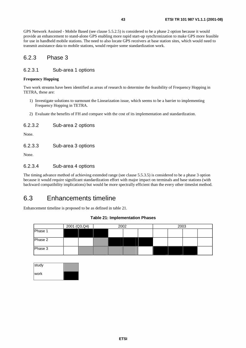
ETSI
ETSI TR 101 987 V1.1.1 (2001-08)43
GPS Network Assisted - Mobile Based (see clause 5.5.2.5) is considered to be a phase 2 option because it wouldprovide an enhancement to stand-alone GPS enabling more rapid start-up synchronization to make GPS more feasiblefor use in handheld mobile stations. The need to also locate GPS receivers at base station sites, which would need totransmit assistance data to mobile stations, would require some standardization work.
6.2.3 Phase 3
6.2.3.1 Sub-area 1 options
Frequency Hopping
Two work streams have been identified as areas of research to determine the feasibility of Frequency Hopping inTETRA, these are:
1) Investigate solutions to surmount the Linearization issue, which seems to be a barrier to implementingFrequency Hopping in TETRA.
2) Evaluate the benefits of FH and compare with the cost of its implementation and standardization.
6.2.3.2 Sub-area 2 options
None.
6.2.3.3 Sub-area 3 options
None.
6.2.3.4 Sub-area 4 options
The timing advance method of achieving extended range (see clause 5.5.3.5) is considered to be a phase 3 optionbecause it would require significant standardization effort with major impact on terminals and base stations (withbackward compatibility implications) but would be more spectrally efficient than the every other timeslot method.
6.3 Enhancements timelineEnhancement timeline is proposed to be as defined in table 21.
Table 21: Implementation Phases
2001 (Q3,Q4) 2002 2003Phase 1
Phase 2
Phase 3
study
work
ETSI
ETSI TR 101 987 V1.1.1 (2001-08)44
7 Other options
7.1 GeneralSome other options to enhance system performance were considered. These fall into two categories: some of them wereconsidered unfeasible and therefore dismissed at an early stage of TG23 work. The others were not considered orstudied within TG23, but believed to be worthy of studying to determine their feasibility. They can be studied as part ofphase 2 or phase 3. The following two clauses list all the options in each category.
7.2 Sub-area 1
7.2.1 Unfeasible options
These options were considered unfeasible at an early stage of TG23 work. Therefore, they were not pursued any further.These options are:
• Downlink Power Control.
NOTE 1: suggested that downlink power control could reduce system interference. However, implementationissues associated with ramping power up and down on slot-by-slot basis rendered this option unfeasible.
• Modifying Interleaving Schemes for Voice Calls (Inter-frame Interleaving).
NOTE 2: This was suggested to improve the efficiency of channel coding and frequency hopping. However,inter-frame interleaving would increase speech delay. Since one of the requirements of TG23 was toreduce speech delay, inter-frame interleaving was rendered unfeasible and was not pursued any further.
7.2.2 Unstudied options
Some techniques can be used to enhance system performance and improve system quality. Such techniques might havesome air interface requirements in order to be implemented. These techniques are:
1) Smart antennas.
2) Underlay/Overlay.
3) Equalizers and the use of Time Selection Diversity.
4) Directed Retry.
The impact of these techniques on the TETRA air interface was not studied within TG23. A study needs to beconducted to determine the impact of these techniques on the air interface and the feasibility of their implementationand standardization. It is suggested that this feasibility study should be in phase 2 of TETRA Release 2 work.
7.3 Sub-area 2None
7.4 Sub-area 3
7.4.1 Unfeasible Options
Transmission of large segments by "Slot spanning" or "Slot Chaining" (see clause 5.4.1.4) was determined asunfeasible. The increased throughput was insufficient to justify further investigation. The retransmission of failedsegments would further reduce the effective throughput on the Air Interface.
ETSI
ETSI TR 101 987 V1.1.1 (2001-08)45
7.4.2 Unstudied options
The following options mentioned in the "Transmission of Large PDUs" clause above were not discussed within theTG23 forum:
• Use of advanced Link for large PDUs;
• Protocol Configuration for SNDCP.
Implementation of an Advanced Link for large PDUs is a feasible option as it is permitted within the current AirInterface standard [1] clause 24.4.2.1. This option should be considered for discussion within WG3, as it will howeverrequire agreement and discussion to ensure interoperability between different manufacturers equipment.
Enhancing the SNDCP protocol to cater for large amounts of protocol configuration data -is not covered by the currentAir Interface standard [1]. The use of additional SNDCP PDUs for protocol configuration implies potential benefitswhere the current PDUs may become fragmented. If the protocol configuration element exceeds 128 octets then thelimitation imposed by the current SNDCP protocol may need enhancing. However further study is required within WG3to examine the full nature of the perceived problem and the benefits and costs of any proposed solutions.
7.5 Sub-area 4
7.5.1 Unfeasible options
These options were considered unfeasible in the TG23 work. Therefore, they were not pursued any further. Theseoptions are:
Timing Advance / Round Trip Time (TA / RTT) (see clause 5.52.5) because these methods would be limited to alocation accuracy of 1-2 km and would incur unjustifiable implementation costs in the TETRA network.
Angle of Arrival (AoA) (see clause 5.5.2.5) because although it could potentially provide accurate location data ingood propagation conditions it would require both software and hardware changes to the network andco-ordination between base stations. Since reflections and non-line of sight conditions would degrade thelocation accuracy it was considered that the potential, as yet unknown, benefits could not be justified by theadditional standardization work and implementation costs.
Time of Arrival (TOA) and Observed Time Difference (OTD) (see clause 5.5.2.5) would not provide sufficientaccuracy in location measurement compared to other methods and may require more accurate synchronizationand timing resolution plus significant implementation costs. 1 - 2 km accuracy is achievable.
There were no sub-area 4 "other options" which were considered worthy of studying to determine their feasibility.
7.5.2 Unstudied options
None identified.
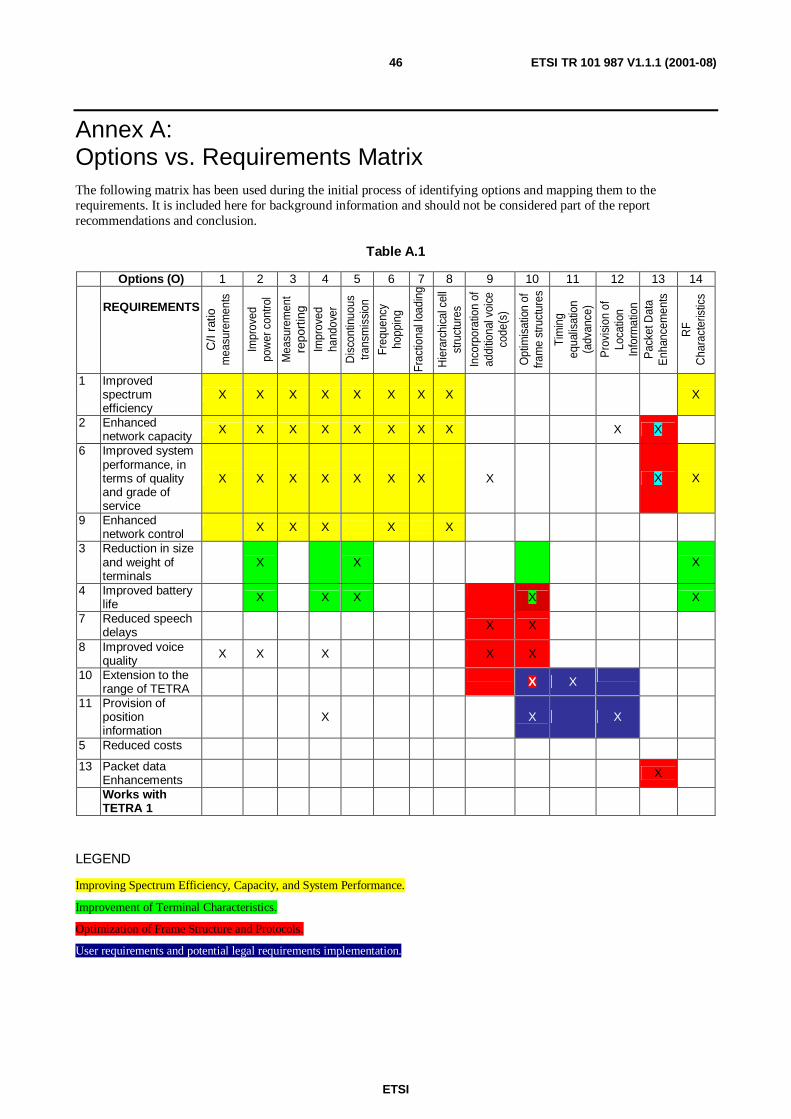
ETSI
ETSI TR 101 987 V1.1.1 (2001-08)46
Annex A:Options vs. Requirements MatrixThe following matrix has been used during the initial process of identifying options and mapping them to therequirements. It is included here for background information and should not be considered part of the reportrecommendations and conclusion.
Table A.1
Options (O) 1 2 3 4 5 6 7 8 9 10 11 12 13 14
REQUIREMENTS
C/I
ratio
mea
sure
men
ts
Impr
oved
pow
erco
ntro
l
Mea
sure
men
tre
port
ing
Impr
oved
hand
over
Dis
cont
inuo
ustra
nsm
issi
on
Freq
uenc
yho
ppin
g
Frac
tiona
lloa
ding
Hie
rarc
hica
lcel
lst
ruct
ures
Inco
rpor
atio
nof
addi
tiona
lvoi
ceco
de(s
)
Opt
imis
atio
nof
fram
est
ruct
ures
Tim
ing
equa
lisat
ion
(adv
ance
)
Pro
visi
onof
Loca
tion
Info
rmat
ion
Pac
ketD
ata
Enh
ance
men
ts
RF
Cha
ract
eris
tics
1 Improvedspectrumefficiency
X X X X X X X X X
2 Enhancednetwork capacity
X X X X X X X X X X
6 Improved systemperformance, interms of qualityand grade ofservice
X X X X X X X X X X
9 Enhancednetwork control
X X X X X
3 Reduction in sizeand weight ofterminals
X X X
4 Improved batterylife
X X X X X
7 Reduced speechdelays
X X
8 Improved voicequality
X X X X X
10 Extension to therange of TETRA
X X
11 Provision ofpositioninformation
X X X
5 Reduced costs
13 Packet dataEnhancements
X
Works withTETRA 1
LEGEND
Improving Spectrum Efficiency, Capacity, and System Performance.
Improvement of Terminal Characteristics.
Optimization of Frame Structure and Protocols.
User requirements and potential legal requirements implementation.
ETSI
ETSI TR 101 987 V1.1.1 (2001-08)47
Annex B:BibliographyTETRA Release 2 Work Programme, EPT13(00)17r1.
Terms of Reference for TG23, EPT MC45(01)05r2.
Terms of Reference for WG2, EPT MC45(01)12r1.
Terms of Reference for WG3, EPT MC45(01)06.
Terms of Reference for the Specialist Task Force JH ("TETRA2") to support EP TETRA for the years 2001 through to2003 in the development of TETRA "Release 2", EPT13(00)16 -ToR JHr11.
Extension of EPT Terms of Reference to Enable TETRA "Release 2" (EPT input to ETSI Board #28), ETSI/B28(00)12.

ETSI
ETSI TR 101 987 V1.1.1 (2001-08)48
History
Document history
V1.1.1 August 2001 Publication