Embed Size (px)
Citation preview
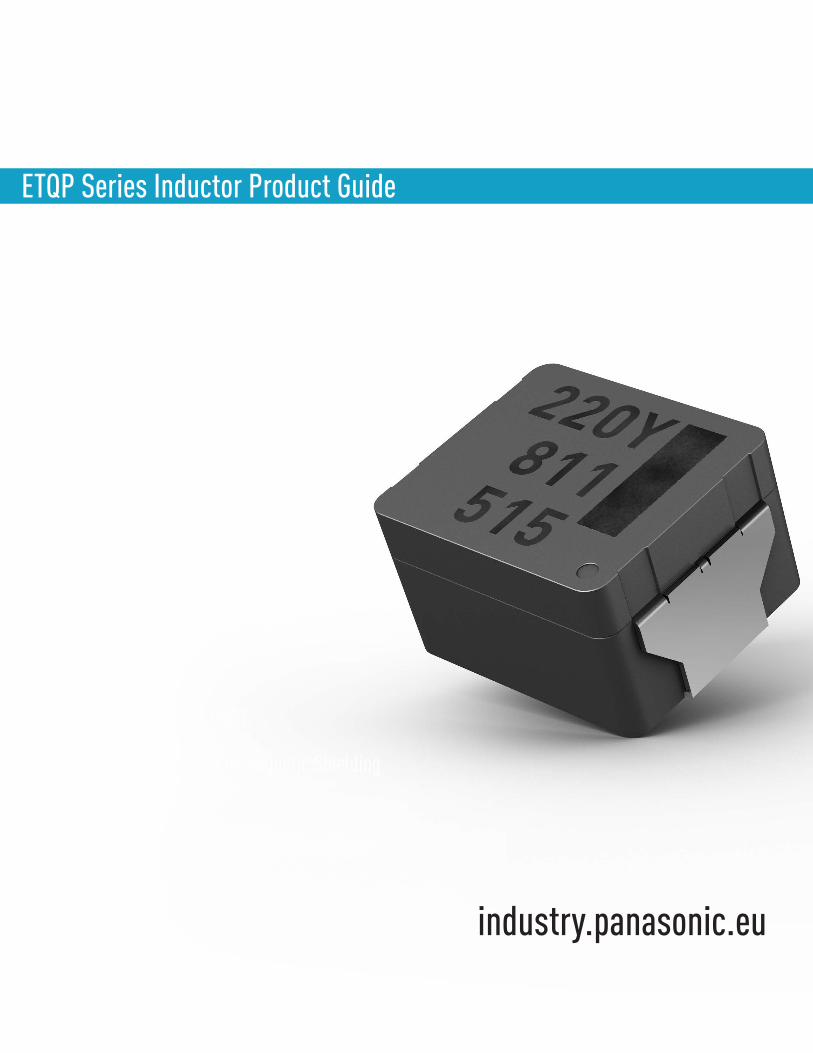
ETQP Series Inductor Product Guide
Metal Composite Type Power Choke Coils
Vibration Resistance of 10G ~ 30G (5Hz – 2kHz)
Up to 40% Smaller
Maximum Operating Temperature of 160°C
Thermal Shock -40 ~+150°C
Metal Composite Core with Magnetic Shielding
Non-Hard Saturation
AEC-Q200 Compliant For Automotive & Industrial Use In Harsh Environments
industry.panasonic.eu
INDEXIntroduction 3Applications 3
Features and BenefitsHigh Current, High Heat Resistance and Excellent Thermal Stability 4Unique Terminal Structure and Mechanical Robustness 5Low Leakage Flux 5AEC-Q200 Compliant for Use in Harsh Environments 6Facilitates Smaller and Lighter Designs 6Acoustic Noise Reduction 7Excellent Withstanding Voltage Characteristics 7
ComparisonPanasonic’s ETQP Series Vs. Alternative Products 8
Explanation of Part NumbersPanasonic’s ETQP Series Part Number Breakdown 9
Selection GuidePanasonic’s ETQP Series Selection Guide 10
ETQP Series Inductor Product Guide
3
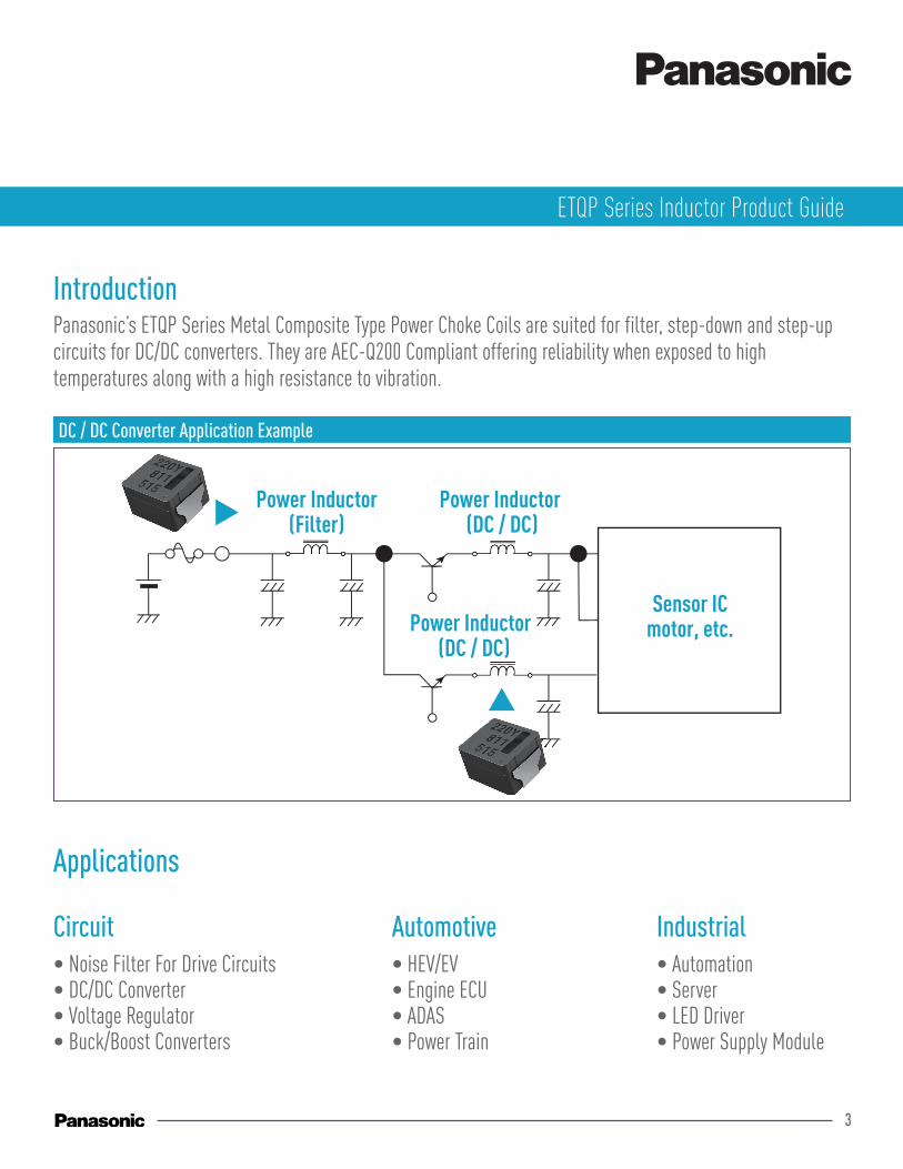
DC / DC Converter Application Example
IntroductionPanasonic’s ETQP Series Metal Composite Type Power Choke Coils are suited for filter, step-down and step-up circuits for DC/DC converters. They are AEC-Q200 Compliant offering reliability when exposed to high temperatures along with a high resistance to vibration.
• Noise Filter For Drive Circuits• DC/DC Converter• Voltage Regulator• Buck/Boost Converters
Applications
Power Inductor(Filter)
Power Inductor (DC / DC)
Power Inductor (DC / DC)
Sensor ICmotor, etc.
• HEV/EV• Engine ECU• ADAS• Power Train
• Automation• Server • LED Driver• Power Supply Module
ETQP Series Inductor Product Guide
Circuit Automotive Industrial
4
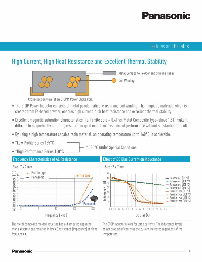
High Current, High Heat Resistance and Excellent Thermal Stability
• The ETQP Power Inductor consists of metal powder, silicone resin and coil winding. The magnetic material, which is created from Fe-based powder, enables high current, high heat resistance and excellent thermal stability.
• Excellent magnetic saturation characteristics (i.e. Ferrite core = 0.4T vs. Metal Composite Type=above 1.5T) make it difficult to magnetically saturate, resulting in good inductance vs. current performance without substantial drop off.
• By using a high temperature capable resin material, an operating temperature up to 160°C is achievable.
• *Low Profile Series 155°C
• *High Performance Series 160°C
The metal composite molded structure has a distributed gap rather than a discrete gap resulting in low AC resistance (impedance) at higher frequencies.
The ETQP Inductor allows for large currents. The inductance levels do not drop significantly as the current increases regardless of the temperature.
Frequency Characteristics of AC Resistance Effect of DC Bias Current on Inductance
012345678910
Ferrite typePanasonic Ferrite type
Panasonic
Size : 7 x 7 mm
Frequency ( kHz )
Size : 7 x 7 mm
0
10
20
30
40
50
60
Indu
ctan
ce ( u
H)
Ferrite type (25 °C)Ferrite type (100°C)Ferrite type (125°C)Ferrite type (150°C)
Panasonic (25 °C)Panasonic (100°C)Panasonic (125°C)Panasonic (150°C)
Coil Winding
Metal Composite Powder and Silicone Resin
Cross-section view of an ETQPM Power Choke Coil.
DC Bias (A)
* 180°C under Special Conditions
Features and Benefits
0.1 1 10 100 1000 0.0 0.2 0.4 0.6 0.8 1.0 1.2 1.4 1.6 1.8 2.0 2.2 2.4 2.6
5
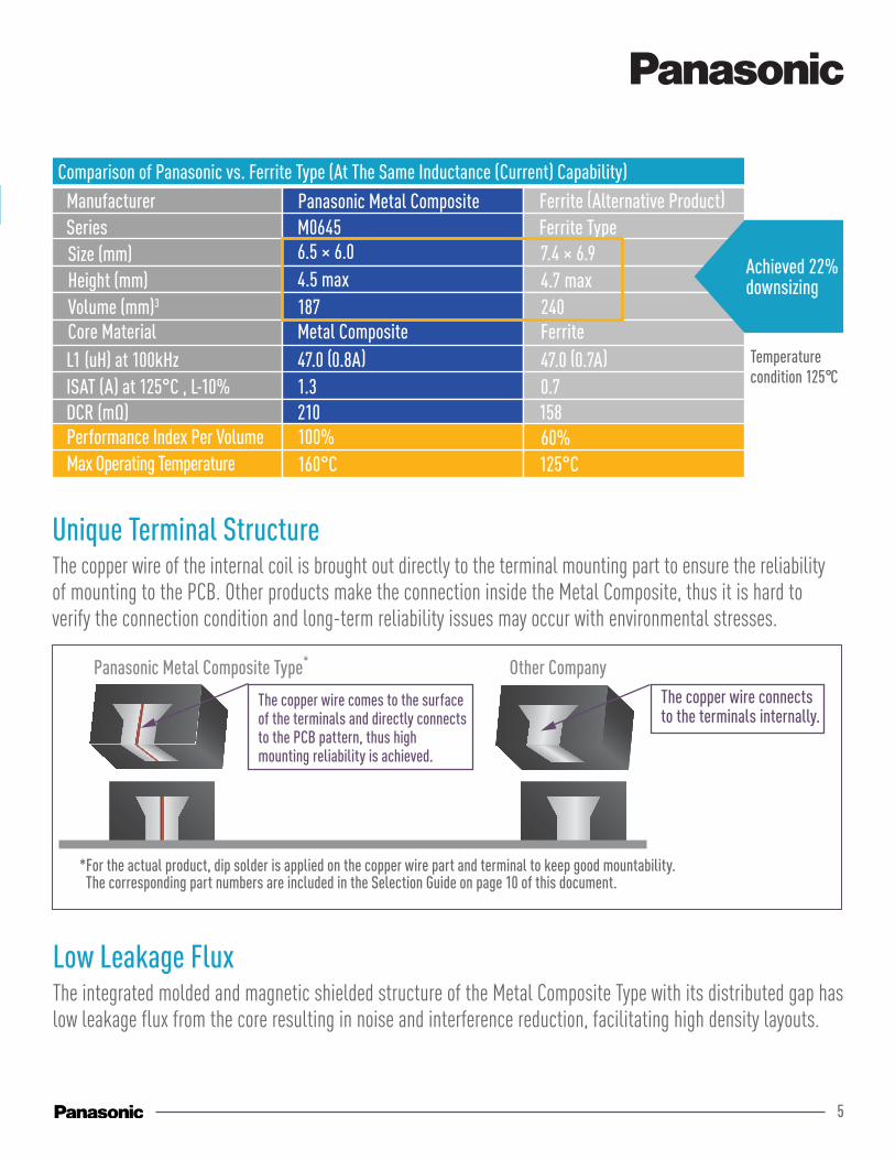
Comparison of Panasonic vs. Ferrite Type (At The Same Inductance (Current) Capability) ManufacturerSeries
Core MaterialL1 (uH) at 100kHzISAT (A) at 125°C , L-10%DCR (mΩ)Performance Index Per VolumeMax Operating Temperature
Size (mm)Height (mm)Volume (mm)3
Panasonic Metal CompositeM0645
Metal Composite47.0 (0.8A)1.3210100%160°C
6.5 × 6.04.5 max187
Ferrite (Alternative Product)Ferrite Type
Ferrite47.0 (0.7A)0.715860%125°C
7.4 × 6.94.7 max240
Achieved 22%downsizing
Temperaturecondition 125°C
Low Leakage FluxThe integrated molded and magnetic shielded structure of the Metal Composite Type with its distributed gap has low leakage flux from the core resulting in noise and interference reduction, facilitating high density layouts.
Unique Terminal StructureThe copper wire of the internal coil is brought out directly to the terminal mounting part to ensure the reliability of mounting to the PCB. Other products make the connection inside the Metal Composite, thus it is hard to verify the connection condition and long-term reliability issues may occur with environmental stresses.
Other CompanyThe copper wire connects to the terminals internally.
*For the actual product, dip solder is applied on the copper wire part and terminal to keep good mountability. The corresponding part numbers are included in the Selection Guide on page 10 of this document.
Panasonic Metal Composite Type*
The copper wire comes to the surface of the terminals and directly connects to the PCB pattern, thus high mounting reliability is achieved.
6
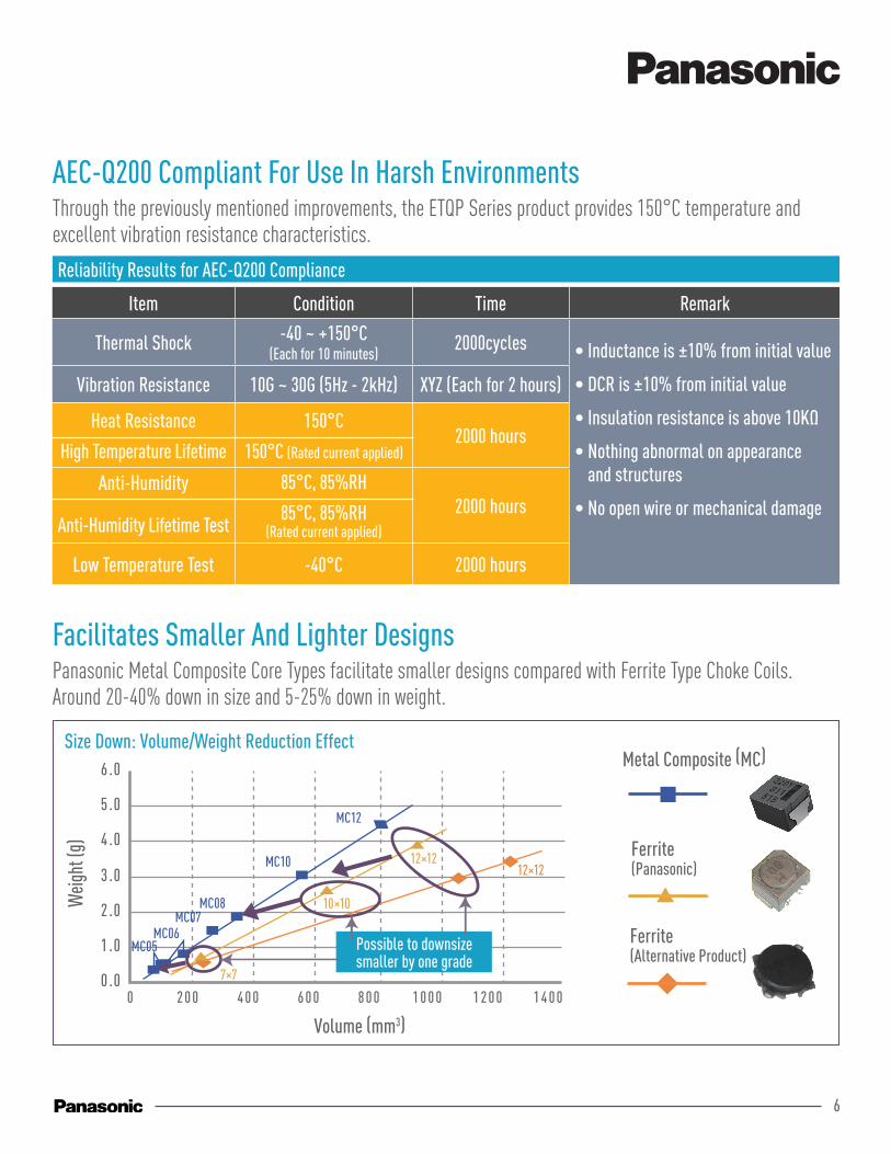
AEC-Q200 Compliant For Use In Harsh EnvironmentsThrough the previously mentioned improvements, the ETQP Series product provides 150°C temperature and excellent vibration resistance characteristics.
Reliability Results for AEC-Q200 Compliance
Item Condition Time Remark
Thermal Shock -40 ~ +150°C (Each for 10 minutes)
2000cycles • Inductance is ±10% from initial value
• DCR is ±10% from initial value
• Insulation resistance is above 10KΩ
• Nothing abnormal on appearance and structures
• No open wire or mechanical damage
Vibration Resistance 10G ~ 30G (5Hz - 2kHz) XYZ (Each for 2 hours)
Heat Resistance
High Temperature Lifetime
150°C
150°C (Rated current applied)2000 hours
Anti-Humidity
Anti-Humidity Lifetime Test
85°C, 85%RH
85°C, 85%RH(Rated current applied)
2000 hours
Low Temperature Test -40°C 2000 hours
Facilitates Smaller And Lighter DesignsPanasonic Metal Composite Core Types facilitate smaller designs compared with Ferrite Type Choke Coils. Around 20-40% down in size and 5-25% down in weight.
MakerSeries
Core materialL1 (uH) at 100kHzISAT (A) at 125°C , L-10%DCR (mΩ)Performance index per volumeMax operating temperature
Size (mm)Height (mm)Volume (mm)3
Panasonic Metal CompositeM0645
Metal composite47.0 (0.8A)1.3210100%150°C
6.5 × 6.04.5 max187
Ferrite (the other company)Ferrite type
Ferrite47.0 (0.7A)0.715860%125°C
7.4 × 6.94.7 max240
Achieved 22%downsizing
Temperaturecondition 125°C
0 2 0 0 4 0 0 6 0 0 8 0 0 1 0 0 0 1 2 0 0 1 4 0 0
Volume (mm3)
0 .0
1 .0
2 .0
3 .0
4 .0
5 .0
6 .0
Weig
ht (g
)
MC12
12×1212×12
10×10
7×7
MC10
MC08MC07
MC06MC05 Possible to downsize
smaller by one grade
Size Down: Volume/Weight Reduction EffectMetal Composite (MC)
Ferrite(Panasonic)
Ferrite(Alternative Product)
7
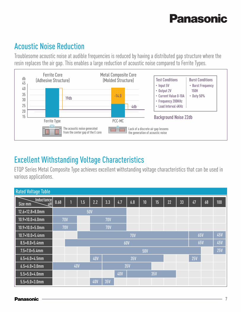
Excellent Withstanding Voltage CharacteristicsETQP Series Metal Composite Type achieves excellent withstanding voltage characteristics that can be used in various applications.
Rated Voltage Table
Size mmInductance
uH
10.9×10.0×6.0mm
10.7×10.0×5.4mm
8.5×8.0×5.4mm
7.5×8.0×5.4mm
6.5×6.0×4.5mm
6.5×6.0×3.0mm
5.5×5.0×4.0mm
5.5×5.0×3.0mm
0.68
70V
10.9×10.0×5.0mm 70V
70V
60V
50V
40V 35V
35V
40V
40V 35V
35V
40V
25V
25V
45V
65V
65V
45V
1 1.5 2.2 3.3 4.7 6.8 10 15 22 33 47 68 100
Panasonic
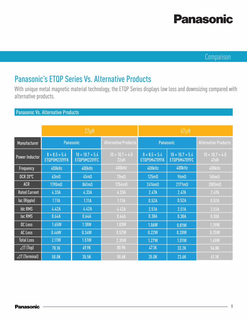
Power Inductor 8 × 8.5 × 5.4ETQP5M220YFK
400kHz63mΩ 45mΩ 70mΩ 125mΩ 96mΩ 165mΩ
1190mΩ4.33A 4.33A 4.33A 2.47A 2.47A 2.47A
1.11A 1.11A 1.11A 0.52A 0.52A 0.52A
4.42A 4.42A 4.42A 2.51A 2.51A 2.51A
0.64A 0.64A 0.64A 0.30A 0.30A 0.30A
1.65W 1.18W 1.83W 1.06W 0.81W 1.39W
0.46W 0.34W 0.52W 0.22W 0.20W 0.25W
2.11W 1.51W 2.35W 1.27W 1.01W 1.65W78.1K 49.9K 80.9K 47.1K 33.2K 56.8K
861mΩ 1254mΩ 2416mΩ 2171mΩ 2805mΩ
400kHz 400kHz 400kHz 400kHz 400kHz
10 × 10.7 × 5.4ETQP5M220YFC
10 × 10.7 × 4.022uH
10 × 10.7 × 4.047uH
8 × 8.5 × 5.4ETQP5M470YFK
10 × 10.7 × 5.4ETQP5M470YFC
Frequency
DCR 20°C
ACR
Rated current
Iac (Ripple)
Idc RMS
Iac RMS
DC loss
AC lossTotall loss⊿T (Top)
⊿T (Terminal)
Other companies Alternative ProductsPanasonic
58.0K 35.5K 58.6K 35.0K 23.6K 41.1K
Size mmInductance
uH
12.6×12.8×8.0mm
10.7×10.0×5.4mm
8.5×8.0×5.4mm
7.5×7.0×5.4mm
6.5×6.0×4.5mm
6.5×6.0×3.0mm
5.5×5.0×4.0mm
5.5×5.0×3.0mm
0.68
50V
10.9×10.0×5.0mm 70V
10.9×10.0×6.0mm 70V 70V
70V
70V
60V
40V 35V
35V
40V
40V 35V
35V
40V
25V
25V
45V
65V
65V
45V
1 1.5 2.2 3.3 4.7 6.8 10 15 22 33 47 68 100
50V
Acoustic Noise ReductionTroublesome acoustic noise at audible frequencies is reduced by having a distributed gap structure where the resin replaces the air gap. This enables a large reduction of acoustic noise compared to Ferrite Types.
15202530354045db
Ferrite Type
Ferrite Core(Adhesive Structure)
19db
PCC-MC
-14.0
Metal Composite Core(Molded Structure)
4db
Background Noise 22db
The acoustic noise generated from the center gap of the E core
Lack of a discrete air gap lessens the generation of acoustic noise
・Input 5V・Output 2V・Current Value 0-10A・Frequency 200KHz・Load Interval 4KHz
Test Conditions Burst Conditions・Burst Frequency 150H・Duty 50%
8
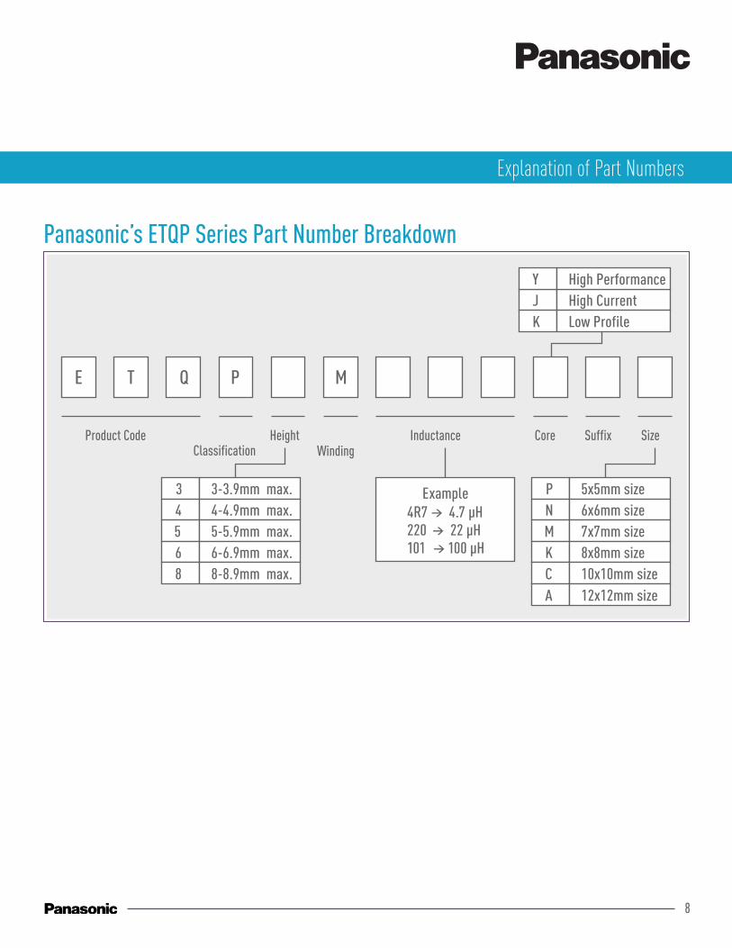
Panasonic’s ETQP Series Part Number Breakdown
Explanation of Part Numbers
Size mmPanasonic
Power Inductor 8 × 8.5 × 5.4ETQP5M220YFK
400kHz63mΩ 45mΩ 70mΩ 125mΩ 96mΩ 165mΩ
1190mΩ4.33A 4.33A 4.33A 2.47A 2.47A 2.47A1.11A 1.11A 1.11A 0.52A 0.52A 0.52A4.42A 4.42A 4.42A 2.51A 2.51A 2.51A0.64A 0.64A 0.64A 0.30A 0.30A 0.30A1.65W 1.18W 1.83W 1.06W 0.81W 1.39W0.46W 0.34W 0.52W 0.22W 0.20W 0.25W2.11W 1.51W 2.35W 1.27W 1.01W 1.65W
861mΩ 1254mΩ 2416mΩ 2171mΩ 2805mΩ
400kHz 400kHz 400kHz 400kHz 400kHz
10 × 10.7 × 5.4ETQP5M220YFC
10 × 10.7 × 4.022uH
10 × 10.7 × 4.047uH
8 × 8.5 × 5.4ETQP5M470YFK
10 × 10.7 × 5.4ETQP5M470YFC
FrequencyDCR 20°CACRRated currentIac (Ripple)Idc RMSIac RMSDC lossAC lossTotall loss
Other companies Alternative ProductsPanasonic
Product CodeClassification
HeightWinding
Inductance Core Suffix Size
E T Q P M
4R7 → 4.7 μH220 → 22 μH101 → 100 μH
P 5x5mm size6x6mm size7x7mm size8x8mm size10x10mm size
NMKC
12x12mm sizeA
3 3-3.9mm max. 4-4.9mm max.5-5.9mm max.6-6.9mm max.
456
8-8.9mm max.8
High CurrentJHigh PerformanceY
Low ProfileK
Example
9
Panasonic’s ETQP Series Vs. Alternative ProductsWith unique metal magnetic material technology, the ETQP Series displays low loss and downsizing compared with alternative products.
Size mmPanasonic
Power Inductor
Manufacturer
8 × 8.5 × 5.4ETQP5M220YFK
400kHz
63mΩ 45mΩ 125mΩ 96mΩ 165mΩ
1190mΩ
4.33A 4.33A 2.47A 2.47A 2.47A
1.11A 1.11A 0.52A 0.52A 0.52A
4.42A 4.42A 2.51A 2.51A 2.51A0.64A 0.64A 0.30A 0.30A 0.30A
1.65W 1.18W 1.06W 0.81W 1.39W
0.46W 0.34W 0.22W 0.20W 0.25W
2.11W 1.51W 1.27W 1.01W 1.65W
78.1K 49.9K 47.1K 33.2K 56.8K
861mΩ 2416mΩ 2171mΩ 2805mΩ
400kHz 400kHz 400kHz 400kHz
10 × 10.7 × 5.4ETQP5M220YFC
10 × 10.7 × 4.047uH
8 × 8.5 × 5.4ETQP5M470YFK
10 × 10.7 × 5.4ETQP5M470YFC
Frequency
DCR 20°C
ACR
Rated Current
Iac (Ripple)
Idc RMS
Iac RMS
DC Loss
AC Loss
Total Loss
⊿T (Top)
⊿T (Terminal)
Alternative ProductsPanasonic
58.0K 35.5K 35.0K 23.6K 41.1K
70mΩ
4.33A
1.11A
4.42A
0.64A
1.83W
0.52W
2.35W
80.9K
1254mΩ
400kHz
10 × 10.7 × 4.022uH
Alternative Products
58.6K
Panasonic Vs. Alternative Products
Comparison
22μH 47μH
10
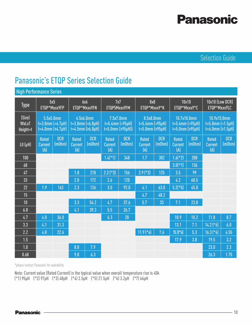
Panasonic’s ETQP Series Selection Guide High Performance Series
Type 5x5 ETQP*MxxxYFP
6x6 ETQP*MxxxYFN
7x7 ETQP5MxxxYFM
8x8 ETQP*MxxxY*K
10x10 ETQP*MxxxY*C
10x10 (Low DCR) ETQP*MxxxYLC
(Size) WxLxT
Height=t
5.5x5.0mmt=3.0mm (<4.7μH)t=4.0mm (≥4.7μH)
6.5x6.0mmt=3.0mm (<6.8μH)t=4.5mm (≥6.8μH)
7.5x7.0mmt=5.4mm (<95μH)t=5.0mm (≥95μH))
8.5x8.0mmt=5.4mm (<95μH)t=5.0mm (≥95μH)
10.7x10.0mmt=5.4mm (<95μH)t=5.0mm (≥95μH)
10.9x10.0mmt=5.0mm (<1.5μH)t=6.0mm (≥1.5μH)
L0 (μH)Rated
Current (A)
DCR(mOhm)
Rated Current
(A)
DCR(mOhm)
Rated Current
(A)
DCR(mOhm)
Rated Current
(A)
DCR(mOhm)
Rated Current
(A)
DCR(mOhm)
Rated Current
(A)
DCR(mOhm)
100 1.4(*1) 348 1.7 302 1.6(*2) 208
68 3.0(*7) 136
47 1.8 210 2.3 (*3) 156 2.9 (*3) 125 3.5 99
33 2.0 172 2.6 120 4.2 68.5
22 1.9 163 2.3 126 3.0 92.0 4.1 63.0 5.2(*5) 45.0
15 4.7 48.2
10 3.3 54.2 4.7 37.6 5.7 33 7.1 23.8
6.8 4.1 39.3 5.5 26.7
4.7 4.0 36.0 6.3 20 10.9 10.2 11.8 8.7
3.3 4.1 31.3 13.1 7.1 14.2 (*6) 6.0
2.2 4.8 22.6 11.9 (*4) 7.6 15.1(*4) 5.3 16.3 (*4) 4.55
1.5 17.9 3.8 19.5 3.2
1.0 8.8 7.9 23.0 2.3
0.68 9.8 6.3 26.3 1.75
Note: Current value (Rated Current) is the typical value when overall temperature rise is 40k(*1) 95μH (*2) 97μH (*3) 48μH (*4) 2.5μH (*5) 21.5μH (*6) 3.2μH (*7) 66μH
*please contact Panasonic for availability
Selection Guide
11
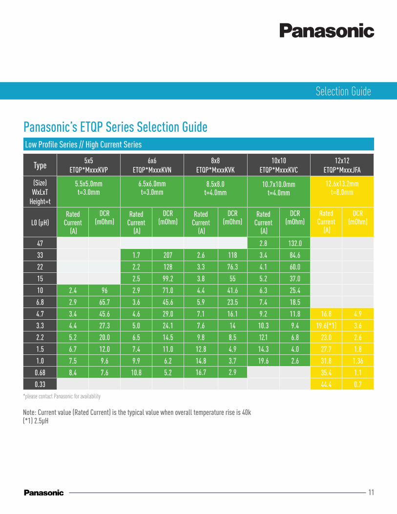
Panasonic’s ETQP Series Selection Guide Low Profile Series // High Current Series
Type 5x5 ETQP*MxxxKVP
6x6 ETQP*MxxxKVN
8x8 ETQP*MxxxKVK
10x10 ETQP*MxxxKVC
12x12 ETQP*MxxxJFA
(Size) WxLxT
Height=t
5.5x5.0mmt=3.0mm
6.5x6.0mmt=3.0mm
8.5x8.0t=4.0mm
10.7x10.0mmt=4.0mm
12.6x13.2mmt=8.0mm
L0 (μH)Rated
Current (A)
DCR(mOhm)
Rated Current
(A)
DCR(mOhm)
Rated Current
(A)
DCR(mOhm)
Rated Current
(A)
DCR(mOhm)
Rated Current
(A)
DCR(mOhm)
47 2.8 132.0
33 1.7 207 2.6 118 3.4 84.6
22 2.2 128 3.3 76.3 4.1 60.0
15 2.5 99.2 3.8 55 5.2 37.0
10 2.4 96 2.9 71.0 4.4 41.6 6.3 25.4
6.8 2.9 65.7 3.6 45.6 5.9 23.5 7.4 18.5
4.7 3.4 45.6 4.6 29.0 7.1 16.1 9.2 11.8 16.8 4.9
3.3 4.4 27.3 5.0 24.1 7.6 14 10.3 9.4 19.6(*1) 3.6
2.2 5.2 20.0 6.5 14.5 9.8 8.5 12.1 6.8 23.0 2.6
1.5 6.7 12.0 7.4 11.0 12.8 4.9 14.3 4.0 27.7 1.8
1.0 7.5 9.6 9.9 6.2 14.8 3.7 19.6 2.6 31.8 1.36
0.68 8.4 7.6 10.8 5.2 16.7 2.9 35.4 1.1
0.33 44.4 0.7
Note: Current value (Rated Current) is the typical value when overall temperature rise is 40k(*1) 2.5μH
*please contact Panasonic for availability
Selection Guide

12
Equivalent circuit models and S-parameterdata can be downloaded for each individual item number.
The Industrial & Automotive use LC filter simulator enables the simulation of attenu-ation amouts when configuring a filter using Panasonic’s power inductor and aluminium electrolytic capacitor suitable for industrial & automotive use.
The Power Inductor loss simulator for auto-motive application enables the simulation of losses and temperature rises according to the current for Panasonic’s power inductors designed for automotive use.
CAD data can be download. (3D STEP, 3D PDF)
Simulation Data Libraries Industrial & AutomotiveUse LC Filter Simulator
Power InductorLoss Simulator
CAD Data
Characteristic Viewer is the tool which rep-resent various characteristics of a selected part by means of a graph of the frequency axis and temperature axis, etc.
Characteristic Viewer
industry.panasonic.eu
Panasonic’s ETQP Design & Sales Support
Our Business Development Team as well as our respective Product Manager are available for technical on-site support.
Local Technical Support
For sample support, please contact Panaso-nic Industry Europe directly.
Sample Support
Panasonic offers for its Power Inductor portfolio a device library for circuit simulators, CAD data as well as many other additional information that help design circuits more efficiently. For further information please refer to the related data as it is listed under the QR code.