Embed Size (px)
Citation preview

E-series™ Routing Platforms
ERX™ Module Guide
Release 9.3.x
Juniper Networks, Inc.1194 North Mathilda Avenue
Sunnyvale, California 94089
USA
408-745-2000
www.juniper.net
Part Number: 162-02000-00, Revision A00

This guide provides an overview and description of the line modules (LMs), switchroute processor (SRP) modules, and I/O modules available for the following E-seriesrouters: ERX-14xx models, ERX-7xx models, and the ERX-310 router.
Unless otherwise specified, all line modules pair with I/O modules to create a modulecombination. Each module combination provides particular capabilities andconnections in an ERX router.
NOTE: A release may support multiple versions of a module. For information, seeSoftware Compatibility in JUNOSe System Basics Configuration Guide, Chapter 6,Managing Modules.
Table 1 on page 3 lists the module combinations supported by ERX routers.
This book also contains three appendixes:
■ Module Protocol Support on page 107
■ Module LEDs on page 133
■ Product Reclamation and Recycling Program on page 139
For more information about ERX routers and modules, refer to the following books:
■ Modules that have reached end-of-life—ERX End-of-Life Module Guide
■ Module installation and maintenance—ERX Hardware Guide
■ Managing ERX routers—JUNOSe System Basics Configuration Guide
■ Configuring ERX modules—JUNOSe Link Layer Configuration Guide
2 ■
ERX 9.3.x Module Guide

Table 1: ERX Module Combinations
Page
FirstJUNOSeSupport
I/O ModuleLabel
Line ModuleLabelCombination Name and Type
Channelized OC3/STM1
92.2.0cOC3 STM1 F0I/O
MULTIMODE
cOCx/STMxF0
cOC3/STM1 multimode
112.2.0cOC3 STM1 F0I/O
SINGLE MODE
cOCx/STMxF0
cOC3/STM1 single-mode intermediatereach
132.2.0cOC3 STM1 F0I/O
LONG HAUL
cOCx/STMxF0
cOC3/STM1 single-mode long reach
Channelized OC12/STM4
152.2.0cOC12 STM4F0 I/O
MULTI MODE
cOCx/STMxF0
cOC12/STM4 multimode without APS/MSPredundancy
172.2.0cOC12 STM4F0 I/O
SINGLE MODE
cOCx/STMxF0
cOC12/STM4 single-mode intermediatereach without APS/MSP redundancy
196.1.3,7.0.2,7.2.0
COC12 F0 APS
SINGLE MODE
cOCx/STMxF0
cOC12/STM4 single-mode intermediatereach with APS/MSP redundancy
212.2.0cOC12 STM4
LONG HAUL
cOCx/STMxF0
cOC12/STM4 single-mode long reach
Channelized T3
233.2.0CT3/T3 12 I/OCT3/T3-F0CT3/T3 12 (12 ports)
E3
244.0.2E3-12
FRAME I/O
COCX-F3E3 Frame (12 ports)
Fast Ethernet
255.0.0FE-8 I/OGE/FEFE-8 (8 ports) (256-MB memory)
266.0.0FE-8 SFP I/OGE/FEFE-8 SFP (8 ports) (256-MB memory)
Gigabit Ethernet (1-port)
285.0.0GE I/O SFPGE/FEGE 1000Base-SX (256-MB memory)
■ 3

Table 1: ERX Module Combinations (continued)
Page
FirstJUNOSeSupport
I/O ModuleLabel
Line ModuleLabelCombination Name and Type
305.0.0GE I/O SFPGE/FEGE 1000Base-LH (256-MB memory)
325.0.0GE I/O SFPGE/FEGE 1000Base-ZX (256-MB memory)
342.0.0GE I/O
MULTI MODE
GE/FEGE multimode
362.0.0GE I/O
SINGLE MODE
GE/FEGE single-mode
Gigabit Ethernet (2-port)
385.3.0GE-2 SFP I/Oor
2XGE APS I/OSFP or
GE-2 APS I/OSFP
GE-2GE2 1000Base-SX
405.3.0GE-2 SFP I/Oor
2XGE APS I/OSFP or
GE-2 APS I/OSFP
GE-2GE2 1000Base-LH
425.3.0GE-2 SFP I/Oor
2XGE APS I/OSFP or
GE-2 APS I/OSFP
GE-2GE2 1000Base-ZX
GE High Density (HDE)
447.0.0GE-2 SFP I/Oor
2XGE APS I/OSFP or
GE-2 APS I/OSFP
GE-HDEGE High Density (2 ports)
467.0.0GE-8 I/OGE-HDEGE High Density (8 ports)
4 ■
ERX 9.3.x Module Guide

Table 1: ERX Module Combinations (continued)
Page
FirstJUNOSeSupport
I/O ModuleLabel
Line ModuleLabelCombination Name and Type
IPSec Service
484.0.2No I/O moduleIPSECSERVICE
IPSec Service
OC3/STM1 ATM
495.0.0,5.3.0
OC3-4 I/O
MULTI MODE
OCx/STMxATM orOCx/STMx/DS3-ATM
OC3/STM1 ATM multimode withoutAPS/MSP redundancy (256-MB memory)
515.1.2
5.2.0(APS/MSP)
4XOC3 APSI/O
MULTI MODE
OCx/STMxATM orOCx/STMx/DS3-ATM
OC3/STM1 ATM multimode with APS/MSPredundancy
535.0.0,5.3.0
OC3-4 I/O
SINGLE MODE
OCx/STMxATM orOCx/STMx/DS3-ATM
OC3/STM1 ATM single-mode intermediatereach without APS/MSP redundancy(256-MB memory)
555.1.2
5.2.0(APS/MSP)
4XOC3
APS I/O
SINGLE MODE
OCx/STMxATM orOCx/STMx/DS3-ATM
OC3/STM1 ATM single-mode intermediatereach with APS/MSP redundancy
575.0.0,5.3.0
OC3-4 I/O
LONG HAUL
OCx/STMxATM orOCx/STMx/DS3-ATM
OC3/STM1 ATM single-mode long reachwithout APS/MSP redundancy (256-MBmemory)
OC3/STM1 GE/FE
596.1.0OC3–2 GEAPS I/O
OC3/STM1GE/FE
OC3/STM1 GE/FE
OC3/STM1 POS
632.0.0OC3-4 I/O
MULTI MODE
OCx/STMxPOS
OC3/STM1 POS multimode withoutAPS/MSP redundancy
655.1.2
5.2.0(APS/MSP)
4XOC3 APSI/O
MULTI MODE
OCx/STMxPOS
OC3/STM1 POS multimode with APS/MSPredundancy
672.0.0OC3-4 I/O
SINGLE MODE
OCx/STMxPOS
OC3/STM1 POS single-mode intermediatereach without APS/MSP redundancy
■ 5
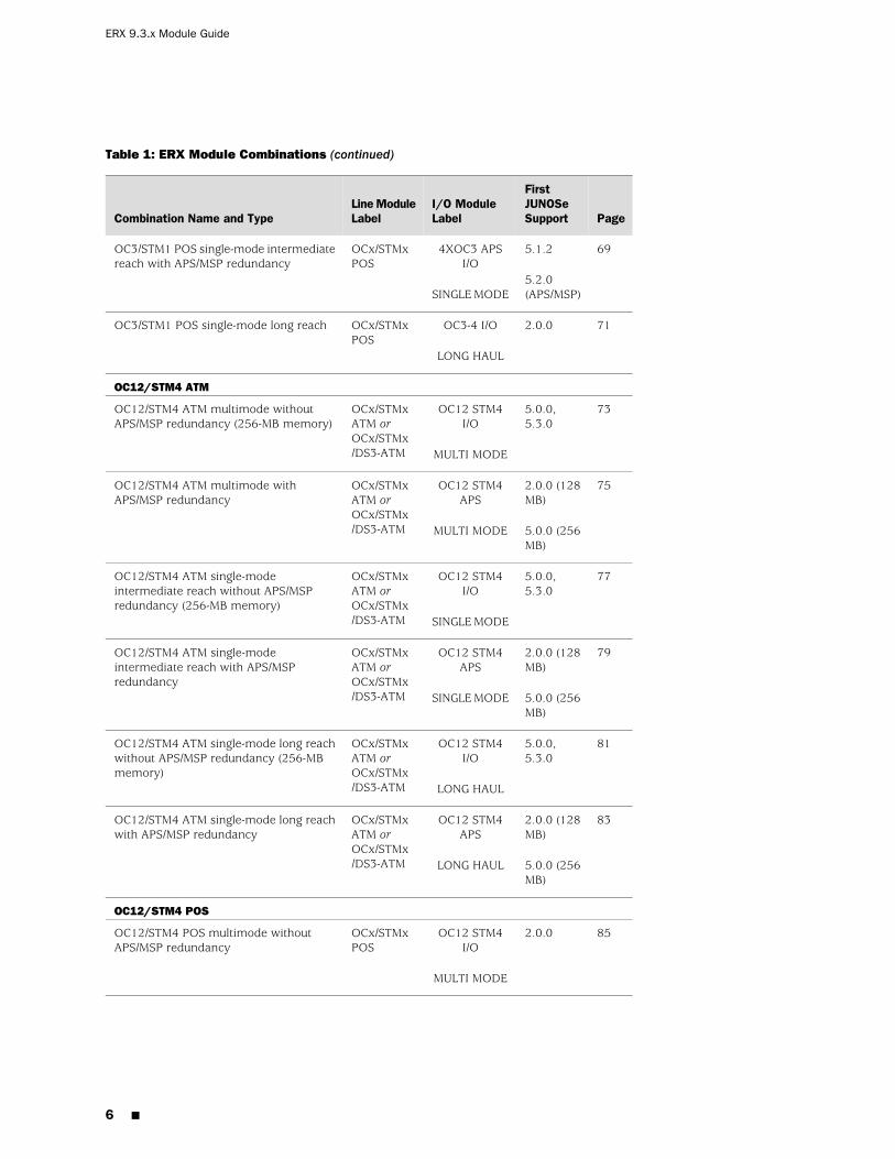
Table 1: ERX Module Combinations (continued)
Page
FirstJUNOSeSupport
I/O ModuleLabel
Line ModuleLabelCombination Name and Type
695.1.2
5.2.0(APS/MSP)
4XOC3 APSI/O
SINGLE MODE
OCx/STMxPOS
OC3/STM1 POS single-mode intermediatereach with APS/MSP redundancy
712.0.0OC3-4 I/O
LONG HAUL
OCx/STMxPOS
OC3/STM1 POS single-mode long reach
OC12/STM4 ATM
735.0.0,5.3.0
OC12 STM4I/O
MULTI MODE
OCx/STMxATM orOCx/STMx/DS3-ATM
OC12/STM4 ATM multimode withoutAPS/MSP redundancy (256-MB memory)
752.0.0 (128MB)
5.0.0 (256MB)
OC12 STM4APS
MULTI MODE
OCx/STMxATM orOCx/STMx/DS3-ATM
OC12/STM4 ATM multimode withAPS/MSP redundancy
775.0.0,5.3.0
OC12 STM4I/O
SINGLE MODE
OCx/STMxATM orOCx/STMx/DS3-ATM
OC12/STM4 ATM single-modeintermediate reach without APS/MSPredundancy (256-MB memory)
792.0.0 (128MB)
5.0.0 (256MB)
OC12 STM4APS
SINGLE MODE
OCx/STMxATM orOCx/STMx/DS3-ATM
OC12/STM4 ATM single-modeintermediate reach with APS/MSPredundancy
815.0.0,5.3.0
OC12 STM4I/O
LONG HAUL
OCx/STMxATM orOCx/STMx/DS3-ATM
OC12/STM4 ATM single-mode long reachwithout APS/MSP redundancy (256-MBmemory)
832.0.0 (128MB)
5.0.0 (256MB)
OC12 STM4APS
LONG HAUL
OCx/STMxATM orOCx/STMx/DS3-ATM
OC12/STM4 ATM single-mode long reachwith APS/MSP redundancy
OC12/STM4 POS
852.0.0OC12 STM4I/O
MULTI MODE
OCx/STMxPOS
OC12/STM4 POS multimode withoutAPS/MSP redundancy
6 ■
ERX 9.3.x Module Guide

Table 1: ERX Module Combinations (continued)
Page
FirstJUNOSeSupport
I/O ModuleLabel
Line ModuleLabelCombination Name and Type
872.0.0OC12 STM4APS
MULTI MODE
OCx/STMxPOS
OC12/STM4 POS multimode withAPS/MSP redundancy
892.0.0OC12 STM4I/O
SINGLE MODE
OCx/STMxPOS
OC12/STM4 POS single-modeintermediate reach without APS/MSPredundancy
912.0.0OC12 STM4APS
SINGLE MODE
OCx/STMxPOS
OC12/STM4 POS single-modeintermediate reach with APS/MSPredundancy
932.0.0OC12 STM4I/O
LONG HAUL
OCx/STMxPOS
OC12/STM4 POS single-mode long reachwithout APS/MSP redundancy
952.0.0OC12 STM4APS
LONG HAUL
OCx/STMxPOS
OC12/STM4 POS single-mode long reachwith APS/MSP redundancy
OC48/STM16
974.1.xOC48 FRAMEAPS
OC48OC48/STM16 POS single-mode short reach
Service Module (SM)
985.1.0No I/O moduleSERVICEMODULE
SM
SRPs
994.1.3,5.0.4,5.1.2,5.2.0
SRP I/OSRP-5G+SRP-5G+ (1-GB memory)
1004.1.3,5.0.4,5.1.2,5.2.0
SRP I/OSRP-5G+SRP-5G+ (2-GB memory)
1014.1.3,5.0.4,5.1.2,5.2.0
SRP I/OSRP-10GSRP-10G (2-GB memory)
1024.0.0SRP I/OSRP-40GPLUS
SRP-40G PLUS (2-GB memory)
■ 7

Table 1: ERX Module Combinations (continued)
Page
FirstJUNOSeSupport
I/O ModuleLabel
Line ModuleLabelCombination Name and Type
1035.3.0SRP-SE I/OSRP-SE10GSRP-SE10G (1-GB memory)
T3
1044.1.0 (128MB)
5.0.0 (256MB)
4xDS3 ATMI/O
OCx/STMxATM orOCx/STMx/DS3-ATM
T3 ATM (4 ports)
1054.0.2CT3/T3 12 I/OCOCX-F3T3 Frame (12 ports)
8 ■
ERX 9.3.x Module Guide
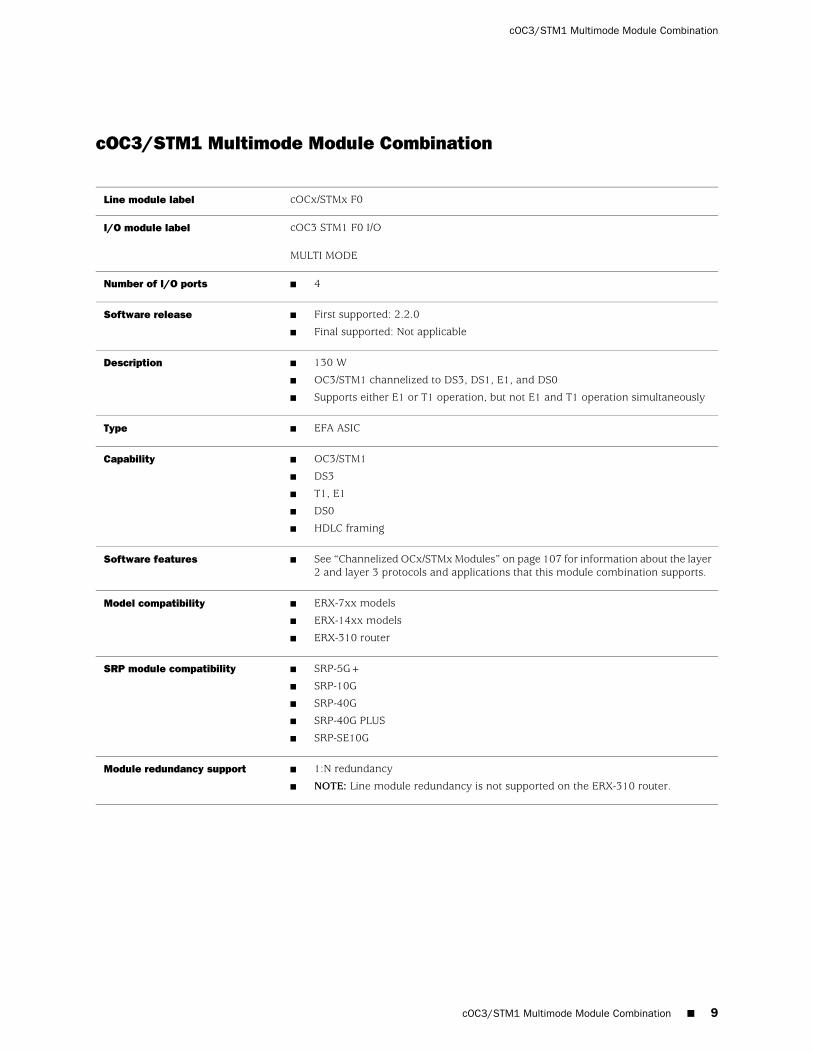
cOC3/STM1 Multimode Module Combination
cOCx/STMx F0Line module label
cOC3 STM1 F0 I/O
MULTI MODE
I/O module label
■ 4Number of I/O ports
■ First supported: 2.2.0
■ Final supported: Not applicable
Software release
■ 130 W
■ OC3/STM1 channelized to DS3, DS1, E1, and DS0
■ Supports either E1 or T1 operation, but not E1 and T1 operation simultaneously
Description
■ EFA ASICType
■ OC3/STM1
■ DS3
■ T1, E1
■ DS0
■ HDLC framing
Capability
■ See “Channelized OCx/STMx Modules” on page 107 for information about the layer2 and layer 3 protocols and applications that this module combination supports.
Software features
■ ERX-7xx models
■ ERX-14xx models
■ ERX-310 router
Model compatibility
■ SRP-5G+
■ SRP-10G
■ SRP-40G
■ SRP-40G PLUS
■ SRP-SE10G
SRP module compatibility
■ 1:N redundancy
■ NOTE: Line module redundancy is not supported on the ERX-310 router.
Module redundancy support
cOC3/STM1 Multimode Module Combination ■ 9
cOC3/STM1 Multimode Module Combination

■ Up to four SC full duplex connectors
■ Tx power:
■ min: –19 dBm
■ max: –14 dBm
■ Center wavelength: 1310 nm
■ Rx input power:
■ min: –30 dBm
■ max: –14 dBm
■ Rated for 2 km (1.2 miles) over 62.5-micron core cable with an optical loss of0–9 dB or 50-micron core cable with an optical loss of 7 dB
■ See ERX Hardware Guide, Chapter 5, Cabling ERX Routers for more information.
Cables and connectors
■ See “Module LEDs” on page 133.LEDs
■ See Monitoring Interfaces in JUNOSe Physical Layer Configuration Guide, Chapter 4,Configuring Channelized OCx/STMx Interfaces.
Alarms, errors, and events
10 ■ cOC3/STM1 Multimode Module Combination
ERX 9.3.x Module Guide

cOC3/STM1 Single-Mode Intermediate Reach Module Combination
cOCx/STMx F0Line module label
cOC3 STM1 F0 I/O
SINGLE MODE
I/O module label
■ 4Number of I/O ports
■ First supported: 2.2.0
■ Final supported: Not applicable
Software release
■ 130 W
■ OC3/STM1 channelized to DS3, DS1, E1, and DS0
Description
■ EFA ASICType
■ OC3/STM1
■ DS3, DS1
■ T1, E1
■ DS0
■ HDLC framing
Capability
■ See “Channelized OCx/STMx Modules” on page 107 for information about thelayer 2 and layer 3 protocols and applications that this module combinationsupports.
Software features
■ ERX-7xx models
■ ERX-14xx models
■ ERX-310 router
Model compatibility
■ SRP-5G+
■ SRP-10G
■ SRP-40G
■ SRP-40G PLUS
■ SRP-SE10G
SRP module compatibility
■ 1:N redundancy
■ NOTE: Line module redundancy is not supported on the ERX-310 router.
Module redundancy support
cOC3/STM1 Single-Mode Intermediate Reach Module Combination ■ 11
cOC3/STM1 Single-Mode Intermediate Reach Module Combination

■ Up to four SC full duplex connectors
■ Tx power:
■ min: –15 dBm
■ max: –8 dBm
■ Center wavelength: 1310 nm
■ Rx input power:
■ min: –31 dBm
■ max: –8 dBm
■ Rated for 15 km (9.3 miles) of 9-micron core cable
■ See ERX Hardware Guide, Chapter 5, Cabling ERX Routers for more information.
Cables and connectors
■ See “Module LEDs” on page 133.LEDs
■ See Monitoring Interfaces in JUNOSe Physical Layer Configuration Guide, Chapter 4,Configuring Channelized OCx/STMx Interfaces.
Alarms, errors, and events
12 ■ cOC3/STM1 Single-Mode Intermediate Reach Module Combination
ERX 9.3.x Module Guide

cOC3/STM1 Single-Mode Long Reach Module Combination
cOCx/STMx F0Line module label
cOC3 STM1 F0 I/O
LONG HAUL
I/O module label
■ 4Number of I/O ports
■ First supported: 2.2.0
■ Final supported: Not applicable
Software release
■ 130 W
■ OC3/STM1 channelized to DS3, DS1, E1, and DS0
Description
■ EFA ASICType
■ OC3/STM1
■ DS3, DS1
■ T1, E1
■ DS0
■ HDLC framing
Capability
■ See “Channelized OCx/STMx Modules” on page 107 for information about thelayer 2 and layer 3 protocols and applications that this module combinationsupports.
Software features
■ ERX-7xx models
■ ERX-14xx models
■ ERX-310 router
Model compatibility
■ SRP-5G+
■ SRP-10G
■ SRP-40G
■ SRP-40G PLUS
■ SRP-SE10G
SRP module compatibility
■ 1:N redundancy
■ NOTE: Line module redundancy is not supported on the ERX-310 router.
Module redundancy support
cOC3/STM1 Single-Mode Long Reach Module Combination ■ 13
cOC3/STM1 Single-Mode Long Reach Module Combination
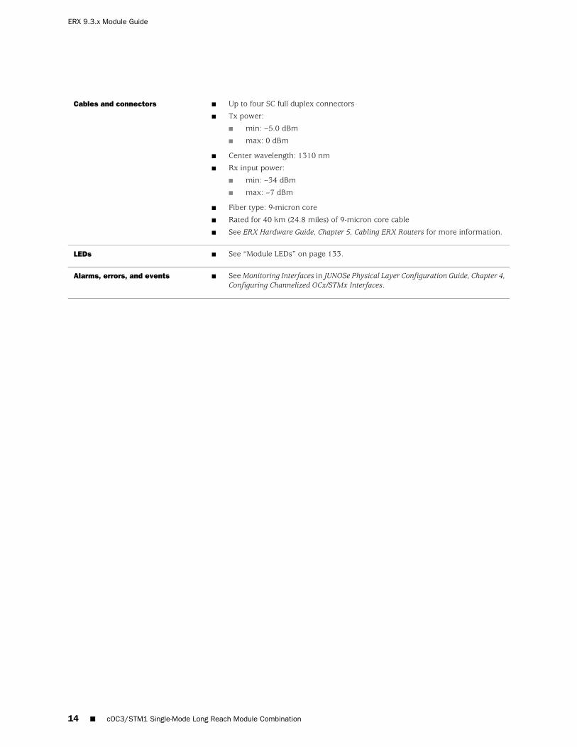
■ Up to four SC full duplex connectors
■ Tx power:
■ min: –5.0 dBm
■ max: 0 dBm
■ Center wavelength: 1310 nm
■ Rx input power:
■ min: –34 dBm
■ max: –7 dBm
■ Fiber type: 9-micron core
■ Rated for 40 km (24.8 miles) of 9-micron core cable
■ See ERX Hardware Guide, Chapter 5, Cabling ERX Routers for more information.
Cables and connectors
■ See “Module LEDs” on page 133.LEDs
■ See Monitoring Interfaces in JUNOSe Physical Layer Configuration Guide, Chapter 4,Configuring Channelized OCx/STMx Interfaces.
Alarms, errors, and events
14 ■ cOC3/STM1 Single-Mode Long Reach Module Combination
ERX 9.3.x Module Guide

cOC12/STM4 Multimode Without APS/MSP Redundancy ModuleCombination
cOCx/STMx F0Line module label
cOC12 STM4 F0 I/O
MULTI MODE
I/O module label
■ 1Number of I/O ports
■ First supported: 2.2.0
■ Final supported: Not applicable
Software release
■ 130 W
■ OC12/STM4 channelized to DS3, DS1, E1, and DS0
Description
■ EFA ASICType
■ OC12/STM4
■ OC3/STM1
■ DS3, DS1
■ T1, E1
■ DS0
■ HDLC framing
Capability
■ See “Channelized OCx/STMx Modules” on page 107 for information about the layer2 and layer 3 protocols and applications that this module combination supports.
Software features
■ ERX-7xx models
■ ERX-14xx models
■ ERX-310 router
Model compatibility
■ SRP-5G+
■ SRP-10G
■ SRP-40G
■ SRP-40G PLUS
■ SRP-SE10G
SRP module compatibility
■ 1:N redundancy
■ NOTE: Line module redundancy is not supported on the ERX-310 router.
Module redundancy support
cOC12/STM4 Multimode Without APS/MSP Redundancy Module Combination ■ 15
cOC12/STM4 Multimode Without APS/MSP Redundancy Module Combination

■ SC full duplex connector
■ Tx power:
■ min: –19 dBm
■ max: –14 dBm
■ Center wavelength: 1310 nm
■ Rx input power:
■ min: –30 dBm
■ max: –14 dBm
■ Rated for 2 km (1.2 miles) over 62.5-micron core cable with an optical loss of 0–9dB or 50-micron core cable with an optical loss of 7 dB
■ See ERX Hardware Guide, Chapter 5, Cabling ERX Routers for more information.
Cables and connectors
■ See “Module LEDs” on page 133.LEDs
■ See Monitoring Interfaces in JUNOSe Physical Layer Configuration Guide, Chapter 4,Configuring Channelized OCx/STMx Interfaces.
Alarms, errors, and events
16 ■ cOC12/STM4 Multimode Without APS/MSP Redundancy Module Combination
ERX 9.3.x Module Guide

cOC12/STM4 Single-Mode Intermediate Reach Without APS/MSPRedundancy Module Combination
cOCx/STMx F0Line module label
cOC12 STM4 F0 I/O
SINGLE MODE
I/O module label
■ 1Number of I/O ports
■ First supported: 2.2.0
■ Final supported: Not applicable
Software release
■ 130 W
■ OC12/STM4 channelized to DS3, DS1, E1, and DS0
Description
■ EFA ASICType
■ OC12/STM4
■ OC3/STM1
■ DS3, DS1
■ T1, E1
■ DS0
■ HDLC framing
Capability
■ See “Channelized OCx/STMx Modules” on page 107 for information about thelayer 2 and layer 3 protocols and applications that this module combinationsupports.
Software features
■ ERX-7xx models
■ ERX-14xx models
■ ERX-310 router
Model compatibility
■ SRP-5G+
■ SRP-10G
■ SRP-40G
■ SRP-40G PLUS
■ SRP-SE10G
SRP module compatibility
■ 1:N redundancy
■ NOTE: Line module redundancy is not supported on the ERX-310 router.
Module redundancy support
cOC12/STM4 Single-Mode Intermediate Reach Without APS/MSP Redundancy Module Combination ■ 17
cOC12/STM4 Single-Mode Intermediate Reach Without APS/MSP Redundancy Module Combination

■ SC full duplex connector
■ Tx power:
■ min: –15 dBm
■ max: –8 dBm
■ Center wavelength: 1310 nm
■ Rx input power:
■ min: –31 dBm
■ max: –8 dBm
■ Rated for 15 km (9.3 miles) of 9-micron core cable
■ See ERX Hardware Guide, Chapter 5, Cabling ERX Routers for more information.
Cables and connectors
■ See “Module LEDs” on page 133.LEDs
■ See Monitoring Interfaces in JUNOSe Physical Layer Configuration Guide, Chapter 4,Configuring Channelized OCx/STMx Interfaces.
Alarms, errors, and events
18 ■ cOC12/STM4 Single-Mode Intermediate Reach Without APS/MSP Redundancy Module Combination
ERX 9.3.x Module Guide

cOC12/STM4 Single-Mode Intermediate Reach With APS/MSPRedundancy Module Combination
cOCx/STMx F0Line module label
COC12 F0 APS
SINGLE MODE
I/O module label
■ 2
■ 1 active, 1 redundant
Number of I/O ports
■ First supported: 6.1.3 or later 6.1.x release, 7.0.2 or later 7.0.x release, 7.2.0 andhigher-numbered release
Software release
■ 130 W
■ OC12/STM4 channelized to DS3, DS1, E1, and DS0
Description
■ EFA ASICType
■ OC12/STM4
■ OC3/STM1
■ DS3, DS1
■ T1, E1
■ DS0
■ HDLC framing
Capability
■ See “Channelized OCx/STMx Modules” on page 107 for information about the layer2 and layer 3 protocols and applications that this module combination supports.
Software features
■ ERX-7xx models
■ ERX-14xx models
■ ERX-310 router
Model compatibility
■ SRP-5G+
■ SRP-10G
■ SRP-40G
■ SRP-40G PLUS
■ SRP-SE10G
SRP module compatibility
■ 1:N redundancy
■ NOTE: Line module redundancy is not supported on the ERX-310 router.
Module redundancy support
cOC12/STM4 Single-Mode Intermediate Reach With APS/MSP Redundancy Module Combination ■ 19
cOC12/STM4 Single-Mode Intermediate Reach With APS/MSP Redundancy Module Combination
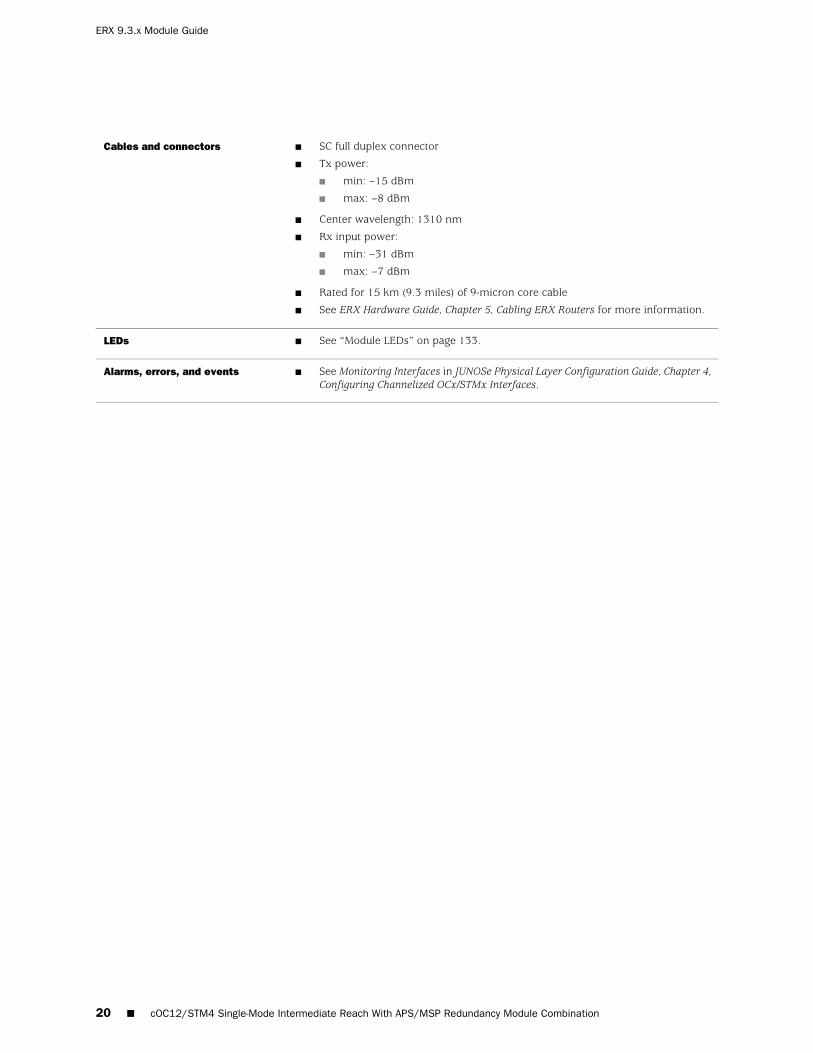
■ SC full duplex connector
■ Tx power:
■ min: –15 dBm
■ max: –8 dBm
■ Center wavelength: 1310 nm
■ Rx input power:
■ min: –31 dBm
■ max: –7 dBm
■ Rated for 15 km (9.3 miles) of 9-micron core cable
■ See ERX Hardware Guide, Chapter 5, Cabling ERX Routers for more information.
Cables and connectors
■ See “Module LEDs” on page 133.LEDs
■ See Monitoring Interfaces in JUNOSe Physical Layer Configuration Guide, Chapter 4,Configuring Channelized OCx/STMx Interfaces.
Alarms, errors, and events
20 ■ cOC12/STM4 Single-Mode Intermediate Reach With APS/MSP Redundancy Module Combination
ERX 9.3.x Module Guide

cOC12/STM4 Single-Mode Long Reach Module Combination
cOCx/STMx F0Line module label
cOC12 STM4
LONG HAUL
I/O module label
■ 1 active, 1 redundantNumber of I/O ports
■ First supported: 2.2.0
■ Final supported: Not applicable
Software release
■ 130 W
■ OC12/STM4 channelized to DS3, DS1, E1, and DS0
Description
■ EFA ASICType
■ OC12/STM4
■ OC3/STM1
■ DS3, DS1
■ T1, E1
■ DS0
■ HDLC framing
Capability
■ See “Channelized OCx/STMx Modules” on page 107 for information about thelayer 2 and layer 3 protocols and applications that this module combinationsupports.
Software features
■ ERX-7xx models
■ ERX-14xx models
■ ERX-310 router
Model compatibility
■ SRP-5G+
■ SRP-10G
■ SRP-40G
■ SRP-40G PLUS
■ SRP-SE10G
SRP module compatibility
■ 1:N redundancy
■ NOTE: Line module redundancy is not supported on the ERX-310 router.
Module redundancy support
cOC12/STM4 Single-Mode Long Reach Module Combination ■ 21
cOC12/STM4 Single-Mode Long Reach Module Combination

■ SC full duplex connector
■ Tx power:
■ min: –5.0 dBm
■ max: 0 dBm
■ Center wavelength: 1310 nm
■ Rx input power:
■ min: –34 dBm
■ max: –7 dBm
■ Fiber type: 9-micron core
■ Rated for 40 km (24.8 miles) of 9-micron core cable
■ See ERX Hardware Guide, Chapter 5, Cabling ERX Routers for more information.
Cables and connectors
■ See “Module LEDs” on page 133.LEDs
■ See Monitoring Interfaces in JUNOSe Physical Layer Configuration Guide, Chapter 4,Configuring Channelized OCx/STMx Interfaces.
Alarms, errors, and events
22 ■ cOC12/STM4 Single-Mode Long Reach Module Combination
ERX 9.3.x Module Guide

CT3/T3 12 Module Combination (12 Ports)
CT3/T3-F0Line module label
CT3/T3 12 I/OI/O module label
■ 12Number of I/O ports
■ First supported: 3.2.0
■ Final supported: Not applicable
Software release
■ 130 W
■ Channelized and unchannelized T3
Description
■ EFA ASICType
■ DS3, DS1, DS0
■ HDLC framing
Capability
■ See “Channelized T3 Modules” on page 110 for information about the layer 2 andlayer 3 protocols and applications that this module combination supports.
Software features
■ ERX-7xx models
■ ERX-14xx models
■ ERX-310 router
Model compatibility
■ SRP-5G+
■ SRP-10G
■ SRP-40G
■ SRP-40G PLUS
■ SRP-SE10G
SRP module compatibility
■ 1:N redundancy
■ NOTE: Line module redundancy is not supported on the ERX-310 router.
Module redundancy support
■ BT43 SMB connector
■ Cable that adapts to 75-ohm BNC is available.
■ The line interface unit supports two line buildouts:
■ 0–68.5 m (0–225 feet)
■ 69–137 m (226–450 feet)
■ Signal strength is software controlled.
■ The transmitted signal complies with ANSI T1.102-1993 Digital Hierarchy -Electrical Interfaces (1999) for cable lengths up to 201 m (660 feet).
■ See ERX Hardware Guide, Chapter 5, Cabling ERX Routers for more information.
Cables and connectors
■ See “Module LEDs” on page 133.LEDs
■ See Monitoring Interfaces in JUNOSe Physical Layer Configuration Guide, Chapter 1,Configuring Channelized T3 Interfaces.
Alarms, errors, and events
CT3/T3 12 Module Combination (12 Ports) ■ 23
CT3/T3 12 Module Combination (12 Ports)
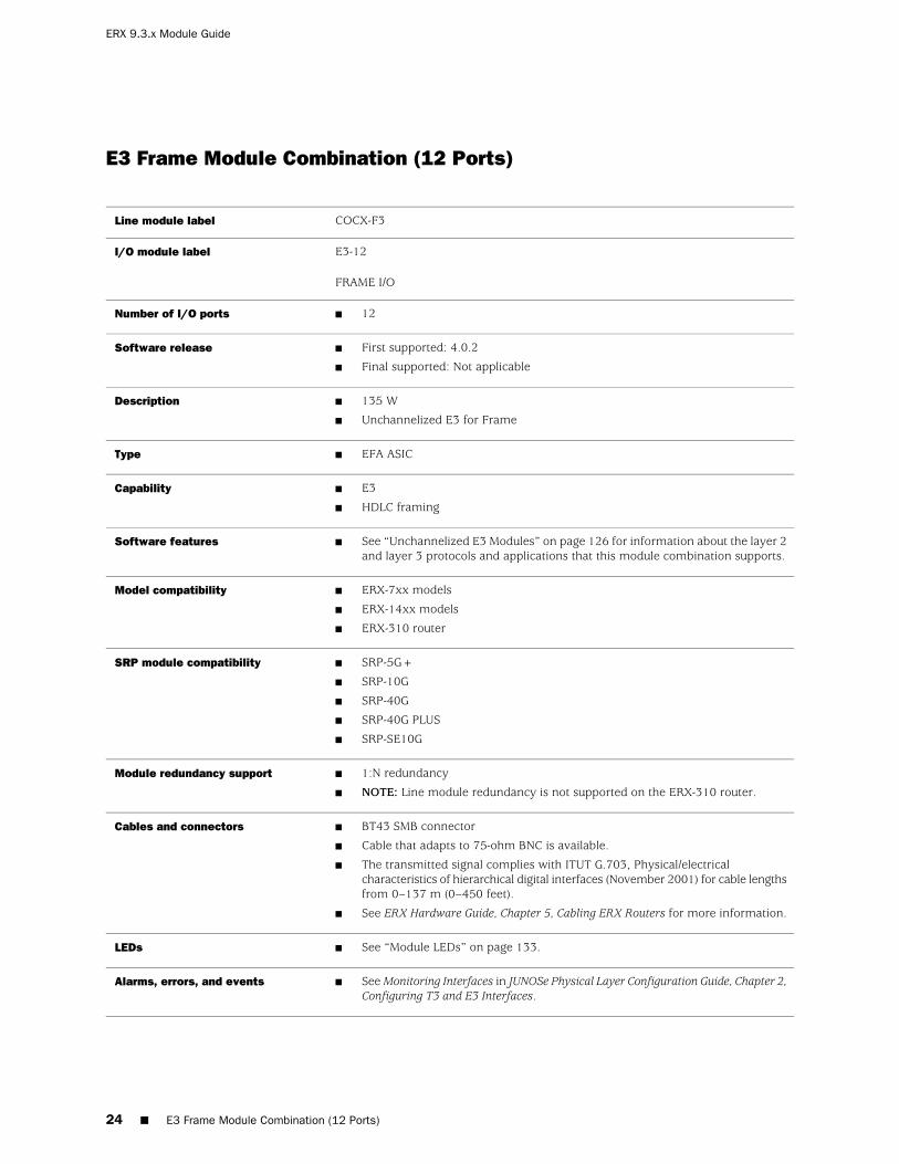
E3 Frame Module Combination (12 Ports)
COCX-F3Line module label
E3-12
FRAME I/O
I/O module label
■ 12Number of I/O ports
■ First supported: 4.0.2
■ Final supported: Not applicable
Software release
■ 135 W
■ Unchannelized E3 for Frame
Description
■ EFA ASICType
■ E3
■ HDLC framing
Capability
■ See “Unchannelized E3 Modules” on page 126 for information about the layer 2and layer 3 protocols and applications that this module combination supports.
Software features
■ ERX-7xx models
■ ERX-14xx models
■ ERX-310 router
Model compatibility
■ SRP-5G+
■ SRP-10G
■ SRP-40G
■ SRP-40G PLUS
■ SRP-SE10G
SRP module compatibility
■ 1:N redundancy
■ NOTE: Line module redundancy is not supported on the ERX-310 router.
Module redundancy support
■ BT43 SMB connector
■ Cable that adapts to 75-ohm BNC is available.
■ The transmitted signal complies with ITUT G.703, Physical/electricalcharacteristics of hierarchical digital interfaces (November 2001) for cable lengthsfrom 0–137 m (0–450 feet).
■ See ERX Hardware Guide, Chapter 5, Cabling ERX Routers for more information.
Cables and connectors
■ See “Module LEDs” on page 133.LEDs
■ See Monitoring Interfaces in JUNOSe Physical Layer Configuration Guide, Chapter 2,Configuring T3 and E3 Interfaces.
Alarms, errors, and events
24 ■ E3 Frame Module Combination (12 Ports)
ERX 9.3.x Module Guide

FE-8 Module Combination (8 Ports) (256-MB Memory)
GE/FELine module label
FE-8 I/OI/O module label
■ 8Number of I/O ports
■ First supported: 5.0.0
■ Final supported: Not applicable
■ The GE/FE line module must have a minimum of 256 MB of memory to be usedwith JUNOSe Release 5.3.0 or a higher-numbered release.
Software release
■ 130 W
■ Fast Ethernet
Description
■ EFA ASICType
■ IEEE 802.3 standards compliance
■ 10/100Base-T
Capability
■ See “Ethernet Modules” on page 112 for information about the layer 2 and layer3 protocols and applications that this module combination supports.
Software features
■ ERX-7xx models
■ ERX-14xx models
■ ERX-310 router
Model compatibility
■ SRP-5G+
■ SRP-10G
■ SRP-40G
■ SRP-40G PLUS
■ SRP-SE10G
SRP module compatibility
■ Not applicableModule redundancy support
■ RJ-45 connectors
■ For 10-Mbps operation, use CAT 3, 4, or 5 UTP cable.
■ For 100-Mbps operation, use only CAT 5 UTP cable.
■ The transmitted signal complies with IEEE 802.3/802.3u for cable lengths up to100 m (328 feet).
■ See ERX Hardware Guide, Chapter 5, Cabling ERX Routers for more information.
Cables and connectors
■ See “Module LEDs” on page 133.LEDs
■ See Monitoring Ethernet Interfaces in JUNOSe Physical Layer Configuration Guide,Chapter 5, Configuring Ethernet Interfaces.
Alarms, errors, and events
FE-8 Module Combination (8 Ports) (256-MB Memory) ■ 25
FE-8 Module Combination (8 Ports) (256-MB Memory)
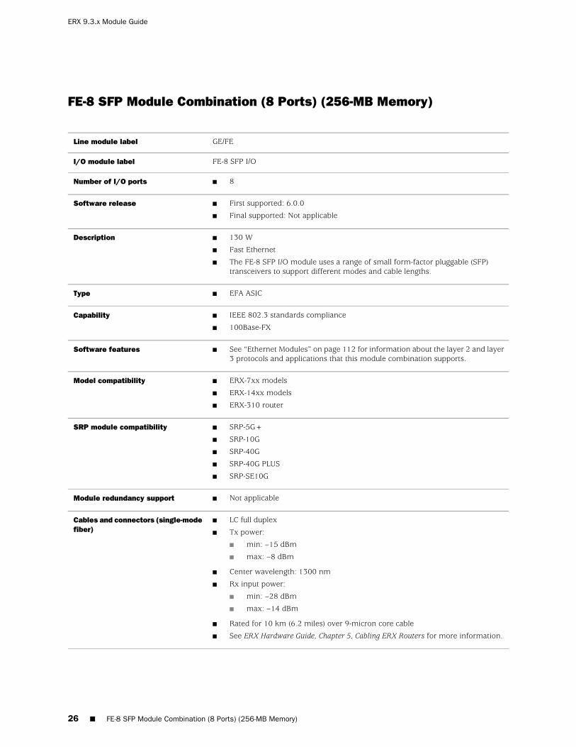
FE-8 SFP Module Combination (8 Ports) (256-MB Memory)
GE/FELine module label
FE-8 SFP I/OI/O module label
■ 8Number of I/O ports
■ First supported: 6.0.0
■ Final supported: Not applicable
Software release
■ 130 W
■ Fast Ethernet
■ The FE-8 SFP I/O module uses a range of small form-factor pluggable (SFP)transceivers to support different modes and cable lengths.
Description
■ EFA ASICType
■ IEEE 802.3 standards compliance
■ 100Base-FX
Capability
■ See “Ethernet Modules” on page 112 for information about the layer 2 and layer3 protocols and applications that this module combination supports.
Software features
■ ERX-7xx models
■ ERX-14xx models
■ ERX-310 router
Model compatibility
■ SRP-5G+
■ SRP-10G
■ SRP-40G
■ SRP-40G PLUS
■ SRP-SE10G
SRP module compatibility
■ Not applicableModule redundancy support
■ LC full duplex
■ Tx power:
■ min: –15 dBm
■ max: –8 dBm
■ Center wavelength: 1300 nm
■ Rx input power:
■ min: –28 dBm
■ max: –14 dBm
■ Rated for 10 km (6.2 miles) over 9-micron core cable
■ See ERX Hardware Guide, Chapter 5, Cabling ERX Routers for more information.
Cables and connectors (single-modefiber)
26 ■ FE-8 SFP Module Combination (8 Ports) (256-MB Memory)
ERX 9.3.x Module Guide

■ LC full duplex
■ Tx power: –20 dBm minimum and –14 dBm maximum
■ Center wavelength: 850 nm
■ Rx input power: –31 dBm minimum and –14 dBm maximum
■ Rated for 2 km (1.2 miles) over 62.5/125-micron core cable
■ See ERX Hardware Guide, Chapter 5, Cabling ERX Routers for more information.
Cables and connectors (multimodefiber)
■ See “Module LEDs” on page 133.LEDs
■ See Monitoring Ethernet Interfaces in JUNOSe Physical Layer Configuration Guide,Chapter 5, Configuring Ethernet Interfaces.
Alarms, errors, and events
FE-8 SFP Module Combination (8 Ports) (256-MB Memory) ■ 27
FE-8 SFP Module Combination (8 Ports) (256-MB Memory)

GE 1000Base-SX Module Combination (1 Port) (256-MB Memory)
GE/FELine module label
GE I/O SFPI/O module label
■ 1 active, 1 redundantNumber of I/O ports
■ First supported: 5.0.0
■ Final supported: Not applicable
Software release
■ 130 W
■ Gigabit Ethernet
■ 256 MB of memory
■ The 128-MB version has reached end-of-life.
■ The I/O module uses a range of small form-factor pluggable (SFP) transceivers tosupport different modes and cabling distances.
■ Uses either optical or copper SFPs.
■ The optical transceivers are 1000Base-SX compliant.
■ The copper transceivers are 1000Base-T compliant.
■ Single-strand SFPs can be used. These SFPs work in pairs and require a matchingSFP at the opposite end of the Ethernet connection. For example, an SFP rated at TX1310, RX 1550 must be paired with an SFP rated TX 1550, RX 1310 with the samemaximum operating range. See the following corresponding table (Single-strand SFPsPairing) for more information.
Description
■ EFA ASICType
■ Ethernet (IEEE 802.3z)
■ 1000Base-SX
Capability
■ See “Ethernet Modules” on page 112 for information about the layer 2 and layer 3protocols and applications that this module combination supports.
Software features
■ ERX-7xx models
■ ERX-14xx models
■ ERX-310 router
Model compatibility
■ SRP-5G+
■ SRP-10G
■ SRP-40G
■ SRP-40G PLUS
■ SRP-SE10G
SRP module compatibility
■ Not applicableModule redundancy support
■ Maximum range is 100 meters on CAT5 cable.Cables and connectors (copperSFP)
28 ■ GE 1000Base-SX Module Combination (1 Port) (256-MB Memory)
ERX 9.3.x Module Guide

■ LC full duplex
■ Tx power:
■ min: –9.5 dBm
■ max: –4 dBm
■ Center wavelength: 850 nm
■ Rx input power:
■ min: –20 dBm
■ max: –0 dBm
■ Rated for 275 m (300 yards) over 62.5-micron core cable
■ Rated for 550 m (601 yards) over 50-micron core cable
■ See ERX Hardware Guide, Chapter 5, Cabling ERX Routers for more information.
Cables and connectors (SX)
■ See “Module LEDs” on page 133.LEDs
■ See Monitoring Ethernet Interfaces in JUNOSe Physical Layer Configuration Guide,Chapter 5, Configuring Ethernet Interfaces.
Alarms, errors, and events
Table 2: Single-strand SFPs Pairing
Maximum Operating Range (kilometers)Nominal Wavelength (nm)Fiber Type
10 (6.2 miles), matching SFP must havethe same operating range
■ TX 1310, RX 1550
■ Pairs with TX 1550 / RX 1310
9 microns
10 (6.2 miles), matching SFP must havethe same operating range
■ TX 1550 / RX 1310
■ Pairs with TX 1310, RX 1550
9 microns
10 (6.2 miles), matching SFP must havethe same operating range
■ TX 1310, RX 1490
■ Pairs with TX 1490 / RX 1310
9 microns
10 (6.2 miles), matching SFP must havethe same operating range
■ TX 1490 / RX 1310
■ Pairs with TX 1310, RX 1490
9 microns
40 (24.85 miles), matching SFP musthave the same operating range
■ TX 1310, RX 1550
■ Pairs with TX 1550 / RX 1310
9 microns
40 (24.85 miles), matching SFP musthave the same operating range
■ TX 1550, RX 1310
■ Pairs with TX 1310 / RX 1550
9 microns
GE 1000Base-SX Module Combination (1 Port) (256-MB Memory) ■ 29
GE 1000Base-SX Module Combination (1 Port) (256-MB Memory)

GE 1000Base-LH Module Combination (1 Port) (256-MB Memory)
GE/FELine module label
GE I/O SFPI/O module label
■ 1 active, 1 redundantNumber of I/O ports
■ First supported: 5.0.0
■ Final supported: Not applicable
Software release
■ 130 W
■ Gigabit Ethernet
■ 256 MB of memory
■ The 128-MB version has reached end-of-life.
■ The I/O module uses a range of small form-factor pluggable (SFP) transceivers tosupport different modes and cabling distances.
■ Uses either optical or copper SFPs.
■ The optical transceivers are 1000Base-LX/LH compliant.
■ The copper transceivers are 1000Base-T compliant.
■ Single-strand SFPs can be used. These SFPs work in pairs and require a matchingSFP at the opposite end of the Ethernet connection. For example, an SFP rated atTX 1310, RX 1550 must be paired with an SFP rated TX 1550, RX 1310 with thesame maximum operating range. See the following corresponding table (Single-strandSFPs Pairing) for more information.
Description
■ EFA ASICType
■ Ethernet (IEEE 802.3z)
■ 1000Base-LH
Capability
■ See “Ethernet Modules” on page 112 for information about the layer 2 and layer 3protocols and applications that this module combination supports.
Software features
■ ERX-7xx models
■ ERX-14xx models
■ ERX-310 router
Model compatibility
■ SRP-5G+
■ SRP-10G
■ SRP-40G
■ SRP-40G PLUS
■ SRP-SE10G
SRP module compatibility
■ Not applicableModule redundancy support
■ Maximum range is 100 meters on CAT5 cable.Cables and connectors (copperSFP)
30 ■ GE 1000Base-LH Module Combination (1 Port) (256-MB Memory)
ERX 9.3.x Module Guide
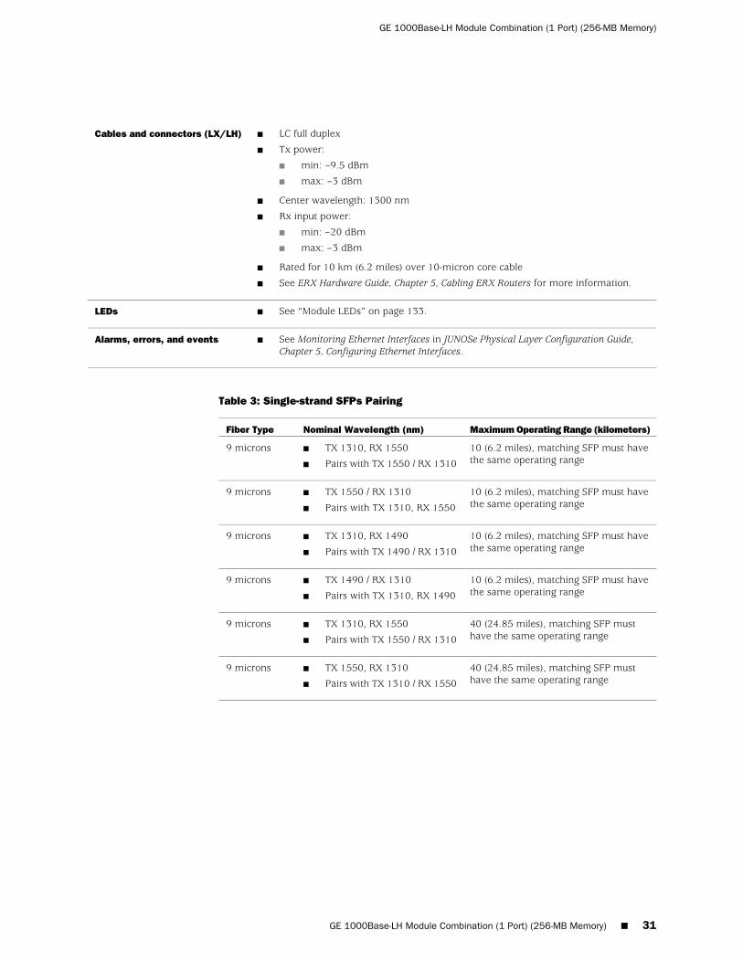
■ LC full duplex
■ Tx power:
■ min: –9.5 dBm
■ max: –3 dBm
■ Center wavelength: 1300 nm
■ Rx input power:
■ min: –20 dBm
■ max: –3 dBm
■ Rated for 10 km (6.2 miles) over 10-micron core cable
■ See ERX Hardware Guide, Chapter 5, Cabling ERX Routers for more information.
Cables and connectors (LX/LH)
■ See “Module LEDs” on page 133.LEDs
■ See Monitoring Ethernet Interfaces in JUNOSe Physical Layer Configuration Guide,Chapter 5, Configuring Ethernet Interfaces.
Alarms, errors, and events
Table 3: Single-strand SFPs Pairing
Maximum Operating Range (kilometers)Nominal Wavelength (nm)Fiber Type
10 (6.2 miles), matching SFP must havethe same operating range
■ TX 1310, RX 1550
■ Pairs with TX 1550 / RX 1310
9 microns
10 (6.2 miles), matching SFP must havethe same operating range
■ TX 1550 / RX 1310
■ Pairs with TX 1310, RX 1550
9 microns
10 (6.2 miles), matching SFP must havethe same operating range
■ TX 1310, RX 1490
■ Pairs with TX 1490 / RX 1310
9 microns
10 (6.2 miles), matching SFP must havethe same operating range
■ TX 1490 / RX 1310
■ Pairs with TX 1310, RX 1490
9 microns
40 (24.85 miles), matching SFP musthave the same operating range
■ TX 1310, RX 1550
■ Pairs with TX 1550 / RX 1310
9 microns
40 (24.85 miles), matching SFP musthave the same operating range
■ TX 1550, RX 1310
■ Pairs with TX 1310 / RX 1550
9 microns
GE 1000Base-LH Module Combination (1 Port) (256-MB Memory) ■ 31
GE 1000Base-LH Module Combination (1 Port) (256-MB Memory)
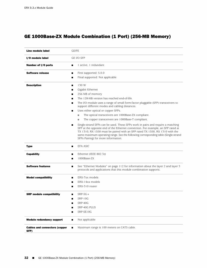
GE 1000Base-ZX Module Combination (1 Port) (256-MB Memory)
GE/FELine module label
GE I/O SFPI/O module label
■ 1 active, 1 redundantNumber of I/O ports
■ First supported: 5.0.0
■ Final supported: Not applicable
Software release
■ 130 W
■ Gigabit Ethernet
■ 256 MB of memory
■ The 128-MB version has reached end-of-life.
■ The I/O module uses a range of small form-factor pluggable (SFP) transceivers tosupport different modes and cabling distances.
■ Uses either optical or copper SFPs.
■ The optical transceivers are 1000Base-ZX compliant.
■ The copper transceivers are 1000Base-T compliant.
■ Single-strand SFPs can be used. These SFPs work in pairs and require a matchingSFP at the opposite end of the Ethernet connection. For example, an SFP rated atTX 1310, RX 1550 must be paired with an SFP rated TX 1550, RX 1310 with thesame maximum operating range. See the following corresponding table (Single-strandSFPs Pairing) for more information.
Description
■ EFA ASICType
■ Ethernet (IEEE 802.3z)
■ 1000Base-ZX
Capability
■ See “Ethernet Modules” on page 112 for information about the layer 2 and layer 3protocols and applications that this module combination supports.
Software features
■ ERX-7xx models
■ ERX-14xx models
■ ERX-310 router
Model compatibility
■ SRP-5G+
■ SRP-10G
■ SRP-40G
■ SRP-40G PLUS
■ SRP-SE10G
SRP module compatibility
■ Not applicableModule redundancy support
■ Maximum range is 100 meters on CAT5 cable.Cables and connectors (copperSFP)
32 ■ GE 1000Base-ZX Module Combination (1 Port) (256-MB Memory)
ERX 9.3.x Module Guide

■ LC full duplex
■ Tx power:
■ min: –2 dBm
■ max: 3 dBm
■ Center wavelength: 1550 nm
■ Rx input power:
■ min: –22 dBm
■ max: –3 dBm
■ Rated for 70 km (43.4 miles) over 10-micron core cable
■ See ERX Hardware Guide, Chapter 5, Cabling ERX Routers for more information.
Cables and connectors (ZX)
■ See “Module LEDs” on page 133.LEDs
■ See Monitoring Ethernet Interfaces in JUNOSe Physical Layer Configuration Guide,Chapter 5, Configuring Ethernet Interfaces.
Alarms, errors, and events
Table 4: Single-strand SFPs Pairing
Maximum Operating Range (kilometers)Nominal Wavelength (nm)Fiber Type
10 (6.2 miles), matching SFP must havethe same operating range
■ TX 1310, RX 1550
■ Pairs with TX 1550 / RX 1310
9 microns
10 (6.2 miles), matching SFP must havethe same operating range
■ TX 1550 / RX 1310
■ Pairs with TX 1310, RX 1550
9 microns
10 (6.2 miles), matching SFP must havethe same operating range
■ TX 1310, RX 1490
■ Pairs with TX 1490 / RX 1310
9 microns
10 (6.2 miles), matching SFP must havethe same operating range
■ TX 1490 / RX 1310
■ Pairs with TX 1310, RX 1490
9 microns
40 (24.85 miles), matching SFP musthave the same operating range
■ TX 1310, RX 1550
■ Pairs with TX 1550 / RX 1310
9 microns
40 (24.85 miles), matching SFP musthave the same operating range
■ TX 1550, RX 1310
■ Pairs with TX 1310 / RX 1550
9 microns
GE 1000Base-ZX Module Combination (1 Port) (256-MB Memory) ■ 33
GE 1000Base-ZX Module Combination (1 Port) (256-MB Memory)

GE Multimode Module Combination (1 Port)
GE/FELine module label
GE I/O
MULTI MODE
I/O module label
■ 1 active, 1 redundantNumber of I/O ports
■ First supported: 2.0.0
■ Final supported: Not applicable
Software release
■ 130 W
■ Gigabit Ethernet
■ This module combination has been superseded by a newer assembly; however,it is supported by current software.
Description
■ EFA ASICType
■ Ethernet (IEEE 802.3z)Capability
■ See “Ethernet Modules” on page 112 for information about the layer 2 and layer3 protocols and applications that this module combination supports.
Software features
■ ERX-7xx models
■ ERX-14xx models
■ ERX-310 router
Model compatibility
■ SRP-5G+
■ SRP-10G
■ SRP-40G
■ SRP-40G PLUS
■ SRP-SE10G
SRP module compatibility
■ Not applicableModule redundancy support
■ SC full duplex
■ Tx power:
■ min: –9.5 dBm
■ max: –4 dBm
■ Center wavelength: 850 nm
■ Rx input power:
■ min: –17 dBm
■ max: –3 dBm
■ Rated for 275 m (300 yards) over 62.5-micron core cable
■ Rated for 550 m (601 yards) over 50-micron core cable
■ See ERX Hardware Guide, Chapter 5, Cabling ERX Routers for more information.
Cables and connectors
34 ■ GE Multimode Module Combination (1 Port)
ERX 9.3.x Module Guide

■ See “Module LEDs” on page 133.LEDs
■ See Monitoring Ethernet Interfaces in JUNOSe Physical Layer Configuration Guide,Chapter 5, Configuring Ethernet Interfaces.
Alarms, errors, and events
GE Multimode Module Combination (1 Port) ■ 35
GE Multimode Module Combination (1 Port)

GE Single-Mode Module Combination (1 Port)
GE/FELine module label
GE I/O
SINGLE MODE
I/O module label
■ 1 active, 1 redundantNumber of I/O ports
■ First supported: 2.0.0
■ Final supported: Not applicable
Software release
■ 130 W
■ Gigabit Ethernet
■ This module combination has been superseded by a newer assembly; however,it is supported by current software.
Description
■ EFA ASICType
■ Ethernet (IEEE 802.3z)Capability
■ See “Ethernet Modules” on page 112 for information about the layer 2 and layer3 protocols and applications that this module combination supports.
Software features
■ ERX-7xx models
■ ERX-14xx models
■ ERX-310 router
Model compatibility
■ SRP-5G+
■ SRP-10G
■ SRP-40G
■ SRP-40G PLUS
■ SRP-SE10G
SRP module compatibility
■ Not applicableModule redundancy support
■ SC full duplex
■ Tx power:
■ min: –11 dBm
■ max: –3 dBm
■ Center wavelength: 1300 nm
■ Rx input power:
■ min: –20 dBm
■ max: –3 dBm
■ Rated for 550 m (601 yards) over 62.5-micron core or 50-micron core MM fiber
■ Rated for 5 km (3.1 miles) over 10-micron core cable
■ See ERX Hardware Guide, Chapter 5, Cabling ERX Routers for more information.
Cables and connectors
36 ■ GE Single-Mode Module Combination (1 Port)
ERX 9.3.x Module Guide

■ See “Module LEDs” on page 133.LEDs
■ See Monitoring Ethernet Interfaces in JUNOSe Physical Layer Configuration Guide,Chapter 5, Configuring Ethernet Interfaces.
Alarms, errors, and events
GE Single-Mode Module Combination (1 Port) ■ 37
GE Single-Mode Module Combination (1 Port)

GE2 1000Base-SX Module Combination (2 Ports)
GE-2Line module label
GE-2 SFP I/O or 2XGE APS I/O SFP or GE-2 APS I/O SFPI/O module label
■ 2 active, 2 redundantNumber of I/O ports
■ First supported: 5.3.0
■ Final supported: Not applicable
Software release
■ 100 W
■ Gigabit Ethernet
■ The I/O module uses a range of small form-factor pluggable (SFP) transceivers tosupport different modes and cabling distances.
■ Uses either optical or copper SFPs.
■ The optical transceivers are 1000Base-SX compliant.
■ The copper transceivers are 1000Base-T compliant.
■ Single-strand SFPs can be used. These SFPs work in pairs and require a matching SFPat the opposite end of the Ethernet connection. For example, an SFP rated at TX 1310,RX 1550 must be paired with an SFP rated TX 1550, RX 1310 with the same maximumoperating range. See the following corresponding table (Single-strand SFPs Pairing)for more information.
■ For information about bandwidth and line rate considerations for the GE2 1000Base-SXmodule combination, see GE–2 SFP I/O Module in JUNOSe Physical Layer ConfigurationGuide, Chapter 5, Configuring Ethernet Interfaces.
Description
■ FFA ASICType
■ Ethernet (IEEE 802.3z)
■ 1000Base-SX
Capability
■ See “Ethernet Modules” on page 112 for information about the layer 2 and layer 3protocols and applications that this module combination supports.
Software features
■ ERX-1440 router
■ ERX-310 router
Model compatibility
■ SRP-40G
■ SRP-40G PLUS
■ SRP-SE10G
SRP module compatibility
■ Not applicableModule redundancy support
■ Maximum range is 100 meters on CAT5 cable.Cables and connectors (copperSFP)
38 ■ GE2 1000Base-SX Module Combination (2 Ports)
ERX 9.3.x Module Guide

■ LC full duplex
■ Tx power:
■ min: –9.5 dBm
■ max: –4 dBm
■ Center wavelength: 850 nm
■ Rx input power:
■ min: –17 dBm
■ max: –3 dBm
■ Rated for 275 m (300 yards) over 62.5-micron core cable
■ Rated for 550 m (601 yards) over 50-micron core cable
■ See ERX Hardware Guide, Chapter 5, Cabling ERX Routers for more information.
Cables and connectors (SX)
■ See “Module LEDs” on page 133.LEDs
■ See Monitoring Ethernet Interfaces in JUNOSe Physical Layer Configuration Guide,Chapter 5, Configuring Ethernet Interfaces.
Alarms, errors, and events
Table 5: Single-strand SFPs Pairing
Maximum Operating Range (kilometers)Nominal Wavelength (nm)Fiber Type
10 (6.2 miles), matching SFP must havethe same operating range
■ TX 1310, RX 1550
■ Pairs with TX 1550 / RX 1310
9 microns
10 (6.2 miles), matching SFP must havethe same operating range
■ TX 1550 / RX 1310
■ Pairs with TX 1310, RX 1550
9 microns
10 (6.2 miles), matching SFP must havethe same operating range
■ TX 1310, RX 1490
■ Pairs with TX 1490 / RX 1310
9 microns
10 (6.2 miles), matching SFP must havethe same operating range
■ TX 1490 / RX 1310
■ Pairs with TX 1310, RX 1490
9 microns
40 (24.85 miles), matching SFP musthave the same operating range
■ TX 1310, RX 1550
■ Pairs with TX 1550 / RX 1310
9 microns
40 (24.85 miles), matching SFP musthave the same operating range
■ TX 1550, RX 1310
■ Pairs with TX 1310 / RX 1550
9 microns
GE2 1000Base-SX Module Combination (2 Ports) ■ 39
GE2 1000Base-SX Module Combination (2 Ports)

GE2 1000Base-LH Module Combination (2 Ports)
GE-2Line module label
GE-2 SFP I/O or 2XGE APS I/O SFP or GE-2 APS I/O SFPI/O module label
■ 2 active, 2 redundantNumber of I/O ports
■ First supported: 5.3.0
■ Final supported: Not applicable
Software release
■ 100 W
■ Gigabit Ethernet
■ The I/O module uses a range of small form-factor pluggable (SFP) transceivers tosupport different modes and cabling distances.
■ Uses either optical or copper SFPs.
■ The optical transceivers are 1000Base-LX/LH compliant.
■ The copper transceivers are 1000Base-T compliant.
■ Single-strand SFPs can be used. These SFPs work in pairs and require a matching SFPat the opposite end of the Ethernet connection. For example, an SFP rated at TX 1310,RX 1550 must be paired with an SFP rated TX 1550, RX 1310 with the same maximumoperating range. See the following corresponding table (Single-strand SFPs Pairing)for more information.
■ For information about bandwidth and line rate considerations for the GE2 1000Base-LHmodule combination, see GE–2 SFP I/O Module in JUNOSe Physical Layer ConfigurationGuide, Chapter 5, Configuring Ethernet Interfaces.
Description
■ FFA ASICType
■ Ethernet (IEEE 802.3z)
■ 1000Base-LH
Capability
■ See “Ethernet Modules” on page 112 for information about the layer 2 and layer 3protocols and applications that this module combination supports.
Software features
■ ERX-1440 router
■ ERX-310 router
Model compatibility
■ SRP-40G
■ SRP-40G PLUS
■ SRP-SE10G
SRP module compatibility
■ Not applicableModule redundancy support
■ Maximum range is 100 meters on CAT5 cable.Cables and connectors (copperSFP)
40 ■ GE2 1000Base-LH Module Combination (2 Ports)
ERX 9.3.x Module Guide

■ LC full duplex
■ Tx power:
■ min: –9.5 dBm
■ max: –3 dBm
■ Center wavelength: 1300 nm
■ Rx input power:
■ min: –20 dBm
■ max: –3 dBm
■ Rated for 10 km (6.2 miles) over 9-micron core cable
■ See ERX Hardware Guide, Chapter 5, Cabling ERX Routers for more information.
Cables and connectors (LX/LH)
■ LC full duplex
■ Tx power:
■ min: –4.5 dBm
■ max: 0 dBm
■ Center wavelength: 1300 nm
■ Rx input power:
■ min: –35 dBm
■ max: –22.5 dBm
■ Rated for 40 km (24.85 miles) over 9-micron core cable
■ See ERX Hardware Guide, Chapter 5, Cabling ERX Routers for more information.
Cables and connectors(single–mode LX40)
■ See “Module LEDs” on page 133.LEDs
■ See Monitoring Ethernet Interfaces in JUNOSe Physical Layer Configuration Guide,Chapter 5, Configuring Ethernet Interfaces.
Alarms, errors, and events
Table 6: Single-strand SFPs Pairing
Maximum Operating Range (kilometers)Nominal Wavelength (nm)Fiber Type
10 (6.2 miles), matching SFP must havethe same operating range
■ TX 1310, RX 1550
■ Pairs with TX 1550 / RX 1310
9 microns
10 (6.2 miles), matching SFP must havethe same operating range
■ TX 1550 / RX 1310
■ Pairs with TX 1310, RX 1550
9 microns
10 (6.2 miles), matching SFP must havethe same operating range
■ TX 1310, RX 1490
■ Pairs with TX 1490 / RX 1310
9 microns
10 (6.2 miles), matching SFP must havethe same operating range
■ TX 1490 / RX 1310
■ Pairs with TX 1310, RX 1490
9 microns
40 (24.85 miles), matching SFP musthave the same operating range
■ TX 1310, RX 1550
■ Pairs with TX 1550 / RX 1310
9 microns
40 (24.85 miles), matching SFP musthave the same operating range
■ TX 1550, RX 1310
■ Pairs with TX 1310 / RX 1550
9 microns
GE2 1000Base-LH Module Combination (2 Ports) ■ 41
GE2 1000Base-LH Module Combination (2 Ports)

GE2 1000Base-ZX Module Combination (2 Ports)
GE-2Line module label
GE-2 SFP I/O or 2XGE APS I/O SFP or GE-2 APS I/O SFPI/O module label
■ 2 active, 2 redundantNumber of I/O ports
■ First supported: 5.3.0
■ Final supported: Not applicable
Software release
■ 100 W
■ Gigabit Ethernet
■ The I/O module uses a range of small form-factor pluggable (SFP) transceivers to supportdifferent modes and cabling distances.
■ Uses either optical or copper SFPs.
■ The optical transceivers are 1000Base-ZX compliant.
■ The copper transceivers are 1000Base-T compliant.
■ Single-strand SFPs can be used. These SFPs work in pairs and require a matching SFPat the opposite end of the Ethernet connection. For example, an SFP rated at TX 1310,RX 1550 must be paired with an SFP rated TX 1550, RX 1310 with the same maximumoperating range. See the following corresponding table (Single-strand SFPs Pairing) formore information.
■ For information about bandwidth and line rate considerations for the GE2 1000Base-ZXmodule combination, see GE-2 SFP I/O Module in JUNOSe Physical Layer ConfigurationGuide, Chapter 5, Configuring Ethernet Interfaces.
Description
■ FFA ASICType
■ Ethernet (IEEE 802.3z)
■ 1000Base-ZX
Capability
■ See “Ethernet Modules” on page 112 for information about the layer 2 and layer 3protocols and applications that this module combination supports.
Software features
■ ERX-1440 router
■ ERX-310 router
Model compatibility
■ SRP-40G
■ SRP-40G PLUS
■ SRP-SE10G
SRP module compatibility
■ Not applicableModule redundancy support
42 ■ GE2 1000Base-ZX Module Combination (2 Ports)
ERX 9.3.x Module Guide

■ LC full duplex
■ Tx power:
■ min: –3 dBm
■ max: 2 dBm
■ Center wavelength: 1550 nm
■ Rx input power:
■ min: –23 dBm
■ max: –3 dBm
■ Rated for 70 km (43.4 miles) over 10-micron core cable
■ See ERX Hardware Guide, Chapter 5, Cabling ERX Routers for more information.
Cables and connectors
■ See “Module LEDs” on page 133.LEDs
■ See Monitoring Ethernet Interfaces in JUNOSe Physical Layer Configuration Guide, Chapter 5,Configuring Ethernet Interfaces.
Alarms, errors, and events
Table 7: Single-strand SFPs Pairing
Maximum Operating Range (kilometers)Nominal Wavelength (nm)Fiber Type
10 (6.2 miles), matching SFP must havethe same operating range
■ TX 1310, RX 1550
■ Pairs with TX 1550 / RX 1310
9 microns
10 (6.2 miles), matching SFP must havethe same operating range
■ TX 1550 / RX 1310
■ Pairs with TX 1310, RX 1550
9 microns
10 (6.2 miles), matching SFP must havethe same operating range
■ TX 1310, RX 1490
■ Pairs with TX 1490 / RX 1310
9 microns
10 (6.2 miles), matching SFP must havethe same operating range
■ TX 1490 / RX 1310
■ Pairs with TX 1310, RX 1490
9 microns
40 (24.85 miles), matching SFP musthave the same operating range
■ TX 1310, RX 1550
■ Pairs with TX 1550 / RX 1310
9 microns
40 (24.85 miles), matching SFP musthave the same operating range
■ TX 1550, RX 1310
■ Pairs with TX 1310 / RX 1550
9 microns
GE2 1000Base-ZX Module Combination (2 Ports) ■ 43
GE2 1000Base-ZX Module Combination (2 Ports)

GE High Density (HDE) Module Combination (2 Ports)
GE-HDELine module label
GE-2 SFP I/O or 2XGE APS I/O SFP or GE-2 APS I/O SFPI/O module label
■ 2 active, 2 redundantNumber of I/O ports
■ First supported: 7.0.0
■ Final supported: Not applicable
Software release
■ 100 W
■ Gigabit Ethernet
■ The I/O module uses a range of small form-factor pluggable (SFP) transceivers tosupport different modes and cabling distances.
■ Uses either optical or copper SFPs.
■ The optical transceivers are 1000Base-LX/LH compliant.
■ The copper transceivers are 1000Base-T compliant.
■ Single-strand SFPs can be used. These SFPs work in pairs and require a matching SFPat the opposite end of the Ethernet connection. For example, an SFP rated at TX 1310,RX 1550 must be paired with an SFP rated TX 1550, RX 1310 with the same maximumoperating range. See the following corresponding table (Single-strand SFPs Pairing)for more information.
■ For information about bandwidth and line rate considerations for the GE–HDE modulecombination, see GE-2 SFP I/O Module in JUNOSe Physical Layer Configuration Guide,Chapter 5, Configuring Ethernet Interfaces.
Description
■ FFA ASICType
■ Ethernet (IEEE 802.3z)
■ 1000Base-LH
Capability
■ See “Ethernet Modules” on page 112 for information about the layer 2 and layer 3protocols and applications that this module combination supports.
Software features
■ ERX-1440 router
■ ERX-310 router
Model compatibility
■ SRP-40G
■ SRP-40G PLUS
■ SRP-SE10G
SRP module compatibility
■ Not applicableModule redundancy support
■ Maximum range is 100 meters on CAT5 cable.Cables and connectors (copperSFP)
44 ■ GE High Density (HDE) Module Combination (2 Ports)
ERX 9.3.x Module Guide

■ LC full duplex
■ Tx power:
■ min: –9.5 dBm
■ max: –3 dBm
■ Center wavelength: 1300 nm
■ Rx input power:
■ min: –20 dBm
■ max: –3 dBm
■ Rated for 10 km (6.2 miles) over 10-micron core cable
■ See ERX Hardware Guide, Chapter 5, Cabling ERX Routers for more information.
Cables and connectors (LX/LH)
■ LC full duplex
■ Tx power:
■ min: –4.5 dBm
■ max: 0 dBm
■ Center wavelength: 1300 nm
■ Rx input power:
■ min: –35 dBm
■ max: –22.5 dBm
■ Rated for 40 km (24.85 miles) over 10-micron core cable
■ See ERX Hardware Guide, Chapter 5, Cabling ERX Routers for more information.
Cables and connectors(single-mode LX40)
■ See “Module LEDs” on page 133.LEDs
■ See Monitoring Ethernet Interfaces in JUNOSe Physical Layer Configuration Guide,Chapter 5, Configuring Ethernet Interfaces.
Alarms, errors, and events
Table 8: Single-strand SFPs Pairing
Maximum Operating Range (kilometers)Nominal Wavelength (nm)Fiber Type
10 (6.2 miles), matching SFP must havethe same operating range
■ TX 1310, RX 1550
■ Pairs with TX 1550 / RX 1310
9 microns
10 (6.2 miles), matching SFP must havethe same operating range
■ TX 1550 / RX 1310
■ Pairs with TX 1310, RX 1550
9 microns
10 (6.2 miles), matching SFP must havethe same operating range
■ TX 1310, RX 1490
■ Pairs with TX 1490 / RX 1310
9 microns
10 (6.2 miles), matching SFP must havethe same operating range
■ TX 1490 / RX 1310
■ Pairs with TX 1310, RX 1490
9 microns
40 (24.85 miles), matching SFP musthave the same operating range
■ TX 1310, RX 1550
■ Pairs with TX 1550 / RX 1310
9 microns
40 (24.85 miles), matching SFP musthave the same operating range
■ TX 1550, RX 1310
■ Pairs with TX 1310 / RX 1550
9 microns
GE High Density (HDE) Module Combination (2 Ports) ■ 45
GE High Density (HDE) Module Combination (2 Ports)

GE High Density (HDE) Module Combination (8 Ports)
GE-HDELine module label
GE-8 I/OI/O module label
■ 8Number of I/O ports
■ First supported: 7.0.0
■ Final supported: Not applicable
Software release
■ 100 W
■ Gigabit Ethernet
■ The I/O module uses a range of small form-factor pluggable (SFP) transceivers to supportdifferent modes and cabling distances.
■ Uses either optical or copper SFPs.
■ The optical transceivers are 1000Base-LX/LH compliant.
■ The copper transceivers are 1000Base-T compliant.
■ Single-strand SFPs can be used. These SFPs work in pairs and require a matching SFPat the opposite end of the Ethernet connection. For example, an SFP rated at TX 1310,RX 1550 must be paired with an SFP rated TX 1550, RX 1310 with the same maximumoperating range. See the following corresponding table (Single-strand SFPs Pairing) formore information.
■ For information about bandwidth and line rate considerations for the GE–HDE modulecombination, see GE-8 I/O Module in JUNOSe Physical Layer Configuration Guide,Chapter 5, Configuring Ethernet Interfaces.
Description
■ FFA ASICType
■ Ethernet (IEEE 802.3z)
■ 1000Base-LH
Capability
■ See “Ethernet Modules” on page 112 for information about the layer 2 and layer 3protocols and applications that this module combination supports.
Software features
■ ERX-1440 router
■ ERX-310 router
Model compatibility
■ SRP-40G
■ SRP-40G PLUS
■ SRP-SE10G
SRP module compatibility
■ Not applicableModule redundancy support
46 ■ GE High Density (HDE) Module Combination (8 Ports)
ERX 9.3.x Module Guide

■ LC full duplex
■ Tx power:
■ min: –9.5 dBm
■ max: –3 dBm
■ Center wavelength: 1300 nm
■ Rx input power:
■ min: –20 dBm
■ max: –3 dBm
■ Rated for 10 km (6.2 miles) over 10-micron core cable
■ See ERX Hardware Guide, Chapter 5, Cabling ERX Routers for more information.
Cables and connectors
■ LC full duplex
■ Tx power:
■ min: –4.5 dBm
■ max: 0 dBm
■ Center wavelength: 1300 nm
■ Rx input power:
■ min: –35 dBm
■ max: –22.5 dBm
■ Rated for 40 km (24.85 miles) over 9-micron core cable
■ See ERX Hardware Guide, Chapter 5, Cabling ERX Routers for more information.
Cables and connectors(single-mode LX40)
■ See “Module LEDs” on page 133.LEDs
■ See Monitoring Ethernet Interfaces in JUNOSe Physical Layer Configuration Guide,Chapter 5, Configuring Ethernet Interfaces.
Alarms, errors, and events
Table 9: Single-strand SFPs Pairing
Maximum Operating Range (kilometers)Nominal Wavelength (nm)Fiber Type
10 (6.2 miles), matching SFP must havethe same operating range
■ TX 1310, RX 1550
■ Pairs with TX 1550 / RX 1310
9 microns
10 (6.2 miles), matching SFP must havethe same operating range
■ TX 1550 / RX 1310
■ Pairs with TX 1310, RX 1550
9 microns
10 (6.2 miles), matching SFP must havethe same operating range
■ TX 1310, RX 1490
■ Pairs with TX 1490 / RX 1310
9 microns
10 (6.2 miles), matching SFP must havethe same operating range
■ TX 1490 / RX 1310
■ Pairs with TX 1310, RX 1490
9 microns
40 (24.85 miles), matching SFP musthave the same operating range
■ TX 1310, RX 1550
■ Pairs with TX 1550 / RX 1310
9 microns
40 (24.85 miles), matching SFP musthave the same operating range
■ TX 1550, RX 1310
■ Pairs with TX 1310 / RX 1550
9 microns
GE High Density (HDE) Module Combination (8 Ports) ■ 47
GE High Density (HDE) Module Combination (8 Ports)

IPSec Service Module Combination
IPSEC SERVICELine module label
No I/O moduleI/O module label
■ Not applicableNumber of I/O ports
■ First supported: 4.0.2
■ Final supported: Not applicable
Software release
■ 130 W
■ IPSec Tunnel Service
Description
■ EFA ASICType
■ IPSec tunnelsCapability
■ See “Service Modules” on page 124 for information about the layer 2 andlayer 3 protocols and applications that this module combination supports.
Software features
■ ERX-7xx models
■ ERX-14xx models
■ ERX-310 router
Model compatibility
■ SRP-5G+
■ SRP-10G
■ SRP-40G
■ SRP-40G PLUS
■ SRP-SE10G
SRP module compatibility
■ Multiple IPSec Service modules provide redundancy.Module redundancy support
■ Not applicableCables and connectors
■ See “Module LEDs” on page 133.LEDs
■ See Monitoring Tunnel-Service Interfaces in JUNOSe Physical LayerConfiguration Guide, Chapter 6, Managing Tunnel-Service and IPSec-ServiceInterfaces.
Alarms, errors, and events
48 ■ IPSec Service Module Combination
ERX 9.3.x Module Guide

OC3/STM1 ATM Multimode Without APS/MSP Redundancy ModuleCombination (256-MB Memory)
OCx/STMx ATM or OCx/STMx /DS3-ATMLine module label
OC3-4 I/O
MULTI MODE
I/O module label
■ 4Number of I/O ports
■ First supported: 5.0.0, 5.3.0 or a higher-numbered release
■ Final supported: Not applicable
Software release
■ 130 W
■ 256 MB of memory
■ The 128-MB version has reached end-of-life.
■ Unchannelized, concatenated OC3/STM1 for ATM
Description
■ EFA ASICType
■ OC3/STM1
■ ATM:AAL5
Capability
■ See “OCx/STMx ATM Modules” on page 119 for information about the layer 2 andlayer 3 protocols and applications that this module combination supports.
Software features
■ ERX-7xx models
■ ERX-14xx models
■ ERX-310 router
Model compatibility
■ SRP-5G+
■ SRP-10G
■ SRP-40G
■ SRP-40G PLUS
■ SRP-SE10G
SRP module compatibility
■ 1:N redundancy
■ NOTE: Line module redundancy is not supported on the ERX-310 router.
Module redundancy support
OC3/STM1 ATM Multimode Without APS/MSP Redundancy Module Combination (256-MB Memory) ■ 49
OC3/STM1 ATM Multimode Without APS/MSP Redundancy Module Combination (256-MB Memory)
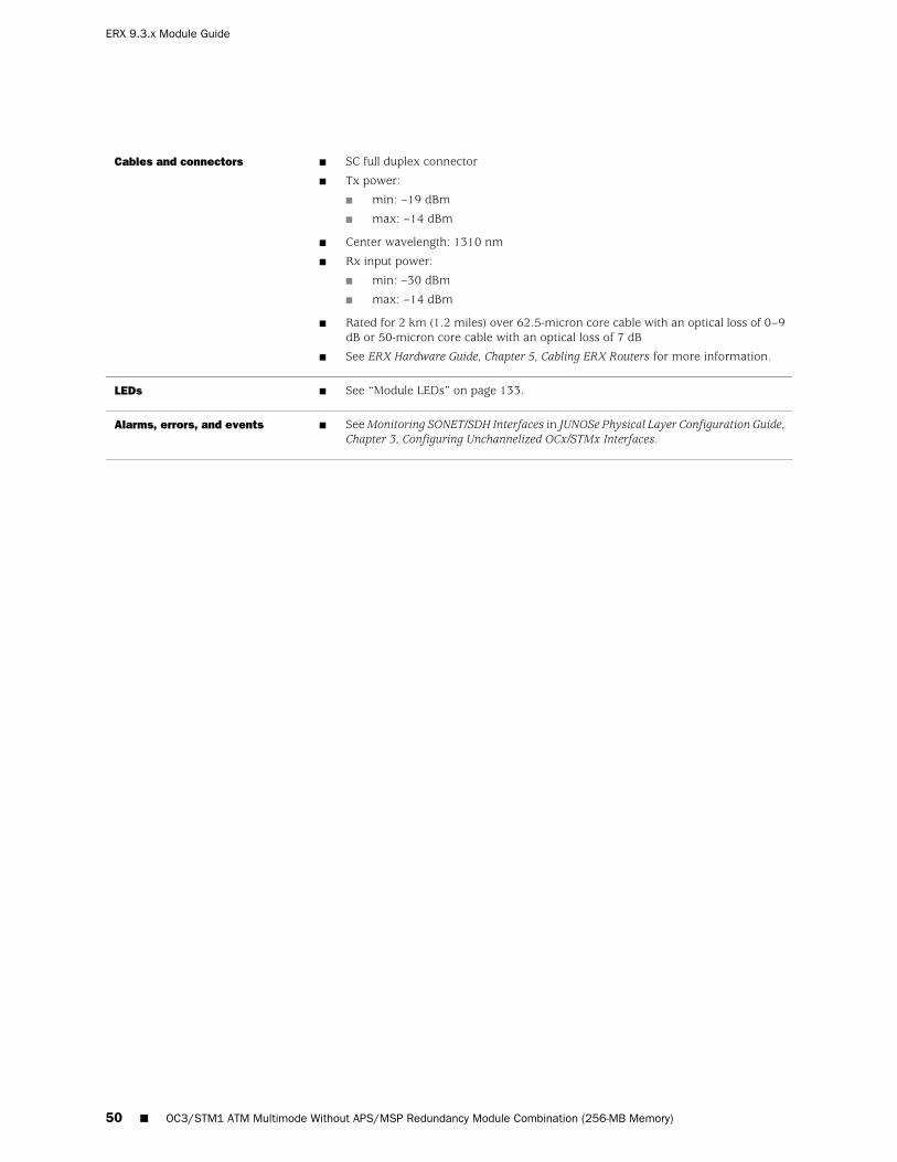
■ SC full duplex connector
■ Tx power:
■ min: –19 dBm
■ max: –14 dBm
■ Center wavelength: 1310 nm
■ Rx input power:
■ min: –30 dBm
■ max: –14 dBm
■ Rated for 2 km (1.2 miles) over 62.5-micron core cable with an optical loss of 0–9dB or 50-micron core cable with an optical loss of 7 dB
■ See ERX Hardware Guide, Chapter 5, Cabling ERX Routers for more information.
Cables and connectors
■ See “Module LEDs” on page 133.LEDs
■ See Monitoring SONET/SDH Interfaces in JUNOSe Physical Layer Configuration Guide,Chapter 3, Configuring Unchannelized OCx/STMx Interfaces.
Alarms, errors, and events
50 ■ OC3/STM1 ATM Multimode Without APS/MSP Redundancy Module Combination (256-MB Memory)
ERX 9.3.x Module Guide

OC3/STM1 ATM Multimode With APS/MSP Redundancy ModuleCombination
OCx/STMx ATM or OCx/STMx /DS3-ATMLine module label
4XOC3
APS I/O
MULTI MODE
I/O module label
■ 4 active, 4 redundantNumber of I/O ports
■ First supported: 5.1.2, 5.2.0 (APS/MSP)
■ Final supported: Not applicable
■ The OCx/STMx ATM line module or the OCx/STMx /DS3-ATM line module must havea minimum of 256 MB of memory to be used with JUNOSe Release 5.3.0 or ahigher-numbered release.
Software release
■ 130 W
■ Can use either the 128-MB OCx/STMx ATM line module or the 256-MB OCx/STMx/DS3-ATM line module.
■ Unchannelized, concatenated OC3/STM1 for ATM
Description
■ EFA ASICType
■ OC3/STM-1
■ ATM/AAL5
Capability
■ See “OCx/STMx ATM Modules” on page 119 for information about the layer 2 andlayer 3 protocols and applications that this module combination supports.
Software features
■ ERX-7xx models
■ ERX-14xx models
■ ERX-310 router
Model compatibility
■ SRP-5G+
■ SRP-10G
■ SRP-40G
■ SRP-40G PLUS
■ SRP-SE10G
SRP module compatibility
■ 1:N redundancy
■ NOTE: Line module redundancy is not supported on the ERX-310 router.
Module redundancy support
OC3/STM1 ATM Multimode With APS/MSP Redundancy Module Combination ■ 51
OC3/STM1 ATM Multimode With APS/MSP Redundancy Module Combination

■ LC full duplex
■ Tx power:
■ min: –19 dBm
■ max: –14 dBm
■ Center wavelength: 1310 nm
■ Rx input power:
■ min: –30 dBm
■ max: –14 dBm
■ Rated for 2 km (1.2 miles) over 62.5-micron core cable with an optical loss of 0–9dB or 50-micron core cable with an optical loss of 7 dB
■ See ERX Hardware Guide, Chapter 5, Cabling ERX Routers for more information.
Cables and connectors
■ See “Module LEDs” on page 133.LEDs
■ See Monitoring SONET/SDH Interfaces in JUNOSe Physical Layer Configuration Guide,Chapter 3, Configuring Unchannelized OCx/STMx Interfaces.
Alarms, errors, and events
52 ■ OC3/STM1 ATM Multimode With APS/MSP Redundancy Module Combination
ERX 9.3.x Module Guide
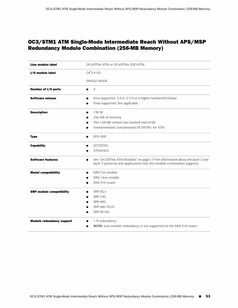
OC3/STM1 ATM Single-Mode Intermediate Reach Without APS/MSPRedundancy Module Combination (256-MB Memory)
OCx/STMx ATM or OCx/STMx /DS3-ATMLine module label
OC3-4 I/O
SINGLE MODE
I/O module label
■ 4Number of I/O ports
■ First supported: 5.0.0, 5.3.0 or a higher-numbered release
■ Final supported: Not applicable
Software release
■ 130 W
■ 256 MB of memory
■ The 128-MB version has reached end-of-life.
■ Unchannelized, concatenated OC3/STM1 for ATM
Description
■ EFA ASICType
■ OC3/STM1
■ ATM/AAL5
Capability
■ See “OCx/STMx ATM Modules” on page 119 for information about the layer 2 andlayer 3 protocols and applications that this module combination supports.
Software features
■ ERX-7xx models
■ ERX-14xx models
■ ERX-310 router
Model compatibility
■ SRP-5G+
■ SRP-10G
■ SRP-40G
■ SRP-40G PLUS
■ SRP-SE10G
SRP module compatibility
■ 1:N redundancy
■ NOTE: Line module redundancy is not supported on the ERX-310 router.
Module redundancy support
OC3/STM1 ATM Single-Mode Intermediate Reach Without APS/MSP Redundancy Module Combination (256-MB Memory) ■ 53
OC3/STM1 ATM Single-Mode Intermediate Reach Without APS/MSP Redundancy Module Combination (256-MB Memory)

■ SC full duplex
■ Tx power:
■ min: –15 dBm
■ max: –8 dBm
■ Center wavelength: 1310 nm
■ Rx input power:
■ min: –31 dBm
■ max: –8 dBm
■ Rated for 15 km (9.3 miles) of 9-micron core cable
■ See ERX Hardware Guide, Chapter 5, Cabling ERX Routers for more information.
Cables and connectors
■ See “Module LEDs” on page 133.LEDs
■ See Monitoring SONET/SDH Interfaces in JUNOSe Physical Layer Configuration Guide,Chapter 3, Configuring Unchannelized OCx/STMx Interfaces.
Alarms, errors, and events
54 ■ OC3/STM1 ATM Single-Mode Intermediate Reach Without APS/MSP Redundancy Module Combination (256-MB Memory)
ERX 9.3.x Module Guide
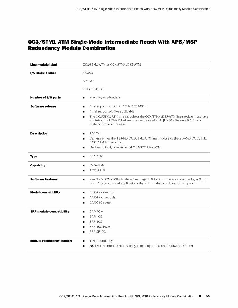
OC3/STM1 ATM Single-Mode Intermediate Reach With APS/MSPRedundancy Module Combination
OCx/STMx ATM or OCx/STMx /DS3-ATMLine module label
4XOC3
APS I/O
SINGLE MODE
I/O module label
■ 4 active, 4 redundantNumber of I/O ports
■ First supported: 5.1.2, 5.2.0 (APS/MSP)
■ Final supported: Not applicable
■ The OCx/STMx ATM line module or the OCx/STMx /DS3-ATM line module must havea minimum of 256 MB of memory to be used with JUNOSe Release 5.3.0 or ahigher-numbered release.
Software release
■ 130 W
■ Can use either the 128-MB OCx/STMx ATM line module or the 256-MB OCx/STMx/DS3-ATM line module.
■ Unchannelized, concatenated OC3/STM1 for ATM
Description
■ EFA ASICType
■ OC3/STM-1
■ ATM/AAL5
Capability
■ See “OCx/STMx ATM Modules” on page 119 for information about the layer 2 andlayer 3 protocols and applications that this module combination supports.
Software features
■ ERX-7xx models
■ ERX-14xx models
■ ERX-310 router
Model compatibility
■ SRP-5G+
■ SRP-10G
■ SRP-40G
■ SRP-40G PLUS
■ SRP-SE10G
SRP module compatibility
■ 1:N redundancy
■ NOTE: Line module redundancy is not supported on the ERX-310 router.
Module redundancy support
OC3/STM1 ATM Single-Mode Intermediate Reach With APS/MSP Redundancy Module Combination ■ 55
OC3/STM1 ATM Single-Mode Intermediate Reach With APS/MSP Redundancy Module Combination

■ LC full duplex
■ Tx power:
■ min: –15 dBm
■ max: –8 dBm
■ Center wavelength: 1310 nm
■ Rx input power:
■ min: –31 dBm
■ max: –8 dBm
■ Rated for 15 km (9.3 miles) of 9-micron core cable
■ See ERX Hardware Guide, Chapter 5, Cabling ERX Routers for more information.
Cables and connectors
■ See “Module LEDs” on page 133.LEDs
■ See Monitoring SONET/SDH Interfaces in JUNOSe Physical Layer Configuration Guide,Chapter 3, Configuring Unchannelized OCx/STMx Interfaces.
Alarms, errors, and events
56 ■ OC3/STM1 ATM Single-Mode Intermediate Reach With APS/MSP Redundancy Module Combination
ERX 9.3.x Module Guide

OC3/STM1 ATM Single-Mode Long Reach Without APS/MSP RedundancyModule Combination (256-MB Memory)
OCx/STMx ATM or OCx/STMx /DS3-ATMLine module label
OC3-4 I/O
LONG HAUL
I/O module label
■ 4Number of I/O ports
■ First supported: 5.0.0, 5.3.0 or a higher-numbered release
■ Final supported: Not applicable
Software release
■ 130 W
■ 256 MB of memory
■ The 128-MB version has reached end-of-life.
■ Unchannelized, concatenated OC3/STM1 for ATM
Description
■ EFA ASICType
■ OC3/STM1
■ ATM/AAL5
Capability
■ See “OCx/STMx ATM Modules” on page 119 for information about the layer 2 andlayer 3 protocols and applications that this module combination supports.
Software features
■ ERX-7xx models
■ ERX-14xx models
■ ERX-310 router
Model compatibility
■ SRP-5G+
■ SRP-10G
■ SRP-40G
■ SRP-40G PLUS
■ SRP-SE10G
SRP module compatibility
■ 1:N redundancy
■ NOTE: Line module redundancy is not supported on the ERX-310 router.
Module redundancy support
OC3/STM1 ATM Single-Mode Long Reach Without APS/MSP Redundancy Module Combination (256-MB Memory) ■ 57
OC3/STM1 ATM Single-Mode Long Reach Without APS/MSP Redundancy Module Combination (256-MB Memory)

■ SC full duplex
■ Tx power:
■ min: –5.0 dBm
■ max: 0 dBm
■ Center wavelength: 1310 nm
■ Rx input power:
■ min: –34 dBm
■ max: –7 dBm
■ Rated for 40 km (24.8 miles) of 9-micron core cable
■ See ERX Hardware Guide, Chapter 5, Cabling ERX Routers for more information.
Cables and connectors
■ See “Module LEDs” on page 133.LEDs
■ See Monitoring SONET/SDH Interfaces in JUNOSe Physical Layer Configuration Guide,Chapter 3, Configuring Unchannelized OCx/STMx Interfaces.
Alarms, errors, and events
58 ■ OC3/STM1 ATM Single-Mode Long Reach Without APS/MSP Redundancy Module Combination (256-MB Memory)
ERX 9.3.x Module Guide

OC3/STM1 GE/FE Module Combination
OC3/STM1 GE/FELine module label
OC3-2 GE APS I/OI/O module label
■ 3; one active and one redundant port per SFP
■ Ports 0 and 1—ATM interfaces
■ Port 2—GE interface
■ Port redundancy is not supported.
Number of I/O ports
■ First supported: 6.1.0
■ Final supported: Not applicable
Software release
■ 150 W
■ Unchannelized OC3/STM1 ATM operation via two line interfaces
and
■ Gigabit Ethernet operation via one line interface
■ The I/O module uses a range of small form-factor pluggable (SFP) transceivers to supportdifferent modes and cabling distances.
■ Depending on the configuration, a variety of SFP combinations can occur.
■ The OC3-2 GE APS I/O module accepts up to three LC-style fiber-optic or copper SFPs.
■ Single-strand SFPs can be used. These SFPs work in pairs and require a matching SFPat the opposite end of the Ethernet connection. For example, an SFP rated at TX 1310,RX 1550 must be paired with an SFP rated TX 1550, RX 1310 with the same maximumoperating range. See the following table (Single-strand SFPs Pairing) for more information.
Description
■ EFA ASICType
■ OC3/STM1
■ ATM/AAL5
■ Ethernet (IEEE 802.3x)
■ 1000Base-LX/SX/ZX
Capability
■ See “OCx/STMx GE/FE Modules” on page 117 for information about the layer 2 and layer3 protocols and applications that this module combination supports.
Software features
■ ERX-7xx models
■ ERX-14xx models
■ ERX-310 router
Model compatibility
■ SRP-5G+
■ SRP-10G
■ SRP-40G
■ SRP-40G PLUS
■ SRP-SE10G
SRP module compatibility
■ Not applicableModule redundancy support
OC3/STM1 GE/FE Module Combination ■ 59
OC3/STM1 GE/FE Module Combination

■ LC-style fiber-optic connectors
■ Tx power:
■ min: –19.0 dBm
■ max: –14dBm
■ Center wavelength: 1310 nm
■ Rx input power:
■ min: –30 dBm
■ max: –14 dBm
■ Rated for 2 km (1.2 miles) over 62.5-micron core cable with an optical loss of 0–9db orover 50-micron core cable with an optical loss of 7 db
■ See ERX Hardware Guide, Chapter 5, Cabling ERX Routers for more information.
Cables and connectors (ATMLX)
■ LC-style fiber-optic connectors
■ Tx power:
■ min: –15.0 dBm
■ max: –8 dBm
■ Center wavelength: 1310 nm
■ Rx input power:
■ min: –31 dBm
■ max: –8 dBm
■ Rated for 15 km (9.3 miles) of 9-micron core cable
■ See ERX Hardware Guide, Chapter 5, Cabling ERX Routers for more information.
Cables and connectors (ATMSX)
■ LC-style fiber-optic connectors
■ Tx power:
■ min: –5.0 dBm
■ max: 0 dBm
■ Center wavelength: 1310 nm
■ Rx input power:
■ min: –34 dBm
■ max: –7 dBm
■ Rated for 40 km (24.8 miles) of 9-micron core cable
■ See ERX Hardware Guide, Chapter 5, Cabling ERX Routers for more information.
Cables and connectors (ATMZX)
■ LC full duplex
■ Tx power:
■ min: –9.5 dBm
■ max: –3 dBm
■ Center wavelength: 1300 nm
■ Rx input power:
■ min: –20 dBm
■ max: –3 dBm
■ Rated for 10 km (6.2 miles) over 10-micron core cable
■ See ERX Hardware Guide, Chapter 5, Cabling ERX Routers for more information.
Cables and connectors (GELX)
60 ■ OC3/STM1 GE/FE Module Combination
ERX 9.3.x Module Guide

■ LC full duplex
■ Tx power:
■ min: –4.5 dBm
■ max: –0 dBm
■ Center wavelength: 1300 nm
■ Rx input power:
■ min: –35 dBm
■ max: –22.5 dBm
■ Rated for 40 km (28.85 miles) over 9-micron core cable
■ See ERX Hardware Guide, Chapter 5, Cabling ERX Routers for more information.
Cables and connectors (GEsingle–mode LX40)
■ LC full duplex
■ Tx power:
■ min: –9.5 dBm
■ max: –4 dBm
■ Center wavelength: 850 nm
■ Rx input power:
■ min: –17 dBm
■ max: –3 dBm
■ Rated for 275 m (300 yards) over 62.5-micron core cable
■ Rated for 550 m (601 yards) over 50-micron core cable
■ See ERX Hardware Guide, Chapter 5, Cabling ERX Routers for more information.
Cables and connectors (GESX)
■ LC full duplex
■ Tx power:
■ min: –3 dBm
■ max: 2 dBm
■ Center wavelength: 1550 nm
■ Rx input power:
■ min: –23 dBm
■ max: –3 dBm
■ Rated for 70 km (43.4 miles) over 10-micron core cable
■ See ERX Hardware Guide, Chapter 5, Cabling ERX Routers for more information.
Cables and connectors (GEZX)
■ See “Module LEDs” on page 133.LEDs
■ See Monitoring SONET/SDH Interfaces in JUNOSe Physical Layer Configuration Guide,Chapter 3, Configuring Unchannelized OCx/STMx Interfaces.
Alarms, errors, and events
Table 10: Single-strand SFPs Pairing
Maximum Operating Range (kilometers)Nominal Wavelength (nm)Fiber Type
10 (6.2 miles), matching SFP must havethe same operating range
■ TX 1310, RX 1550
■ Pairs with TX 1550 / RX 1310
9 microns
OC3/STM1 GE/FE Module Combination ■ 61
OC3/STM1 GE/FE Module Combination

Table 10: Single-strand SFPs Pairing (continued)
10 (6.2 miles), matching SFP must havethe same operating range
■ TX 1550 / RX 1310
■ Pairs with TX 1310, RX 1550
9 microns
10 (6.2 miles), matching SFP must havethe same operating range
■ TX 1310, RX 1490
■ Pairs with TX 1490 / RX 1310
9 microns
10 (6.2 miles), matching SFP must havethe same operating range
■ TX 1490 / RX 1310
■ Pairs with TX 1310, RX 1490
9 microns
40 (24.85 miles), matching SFP musthave the same operating range
■ TX 1310, RX 1550
■ Pairs with TX 1550 / RX 1310
9 microns
40 (24.85 miles), matching SFP musthave the same operating range
■ TX 1550, RX 1310
■ Pairs with TX 1310 / RX 1550
9 microns
62 ■ OC3/STM1 GE/FE Module Combination
ERX 9.3.x Module Guide
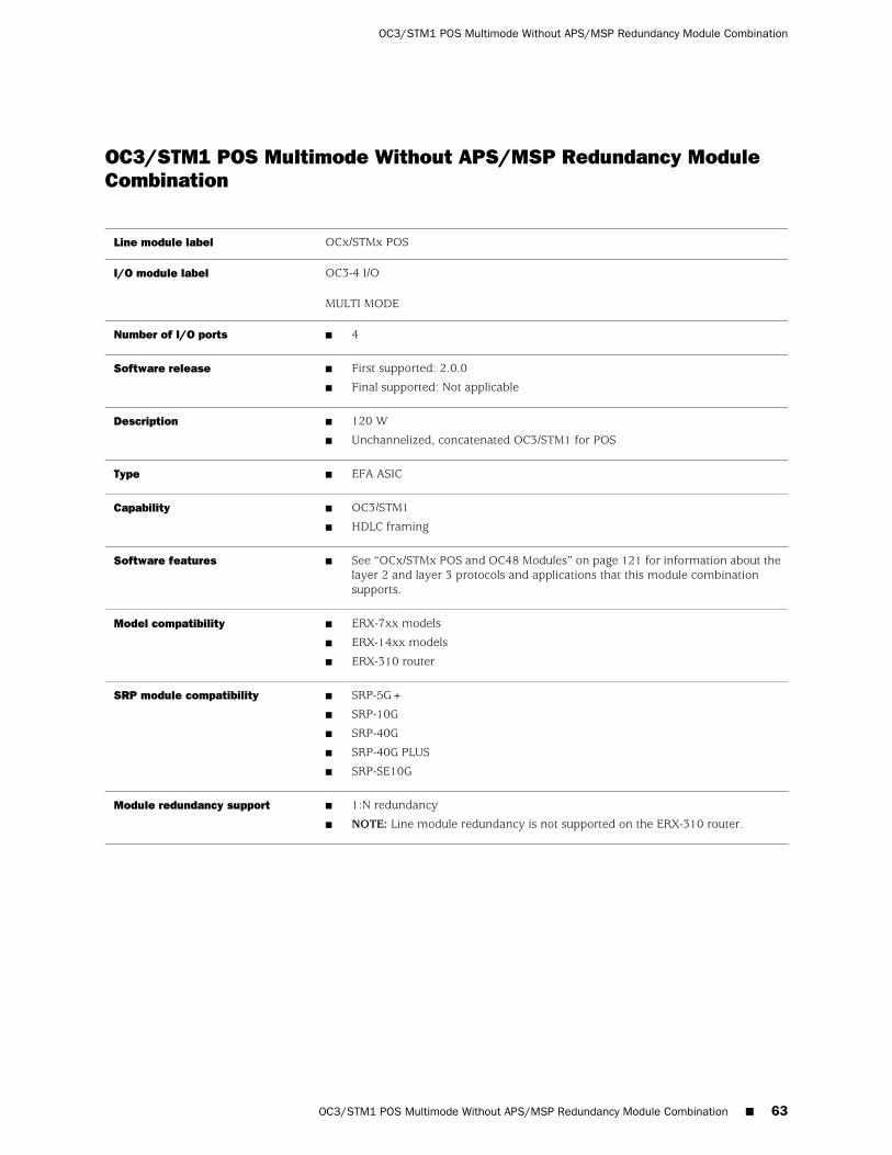
OC3/STM1 POS Multimode Without APS/MSP Redundancy ModuleCombination
OCx/STMx POSLine module label
OC3-4 I/O
MULTI MODE
I/O module label
■ 4Number of I/O ports
■ First supported: 2.0.0
■ Final supported: Not applicable
Software release
■ 120 W
■ Unchannelized, concatenated OC3/STM1 for POS
Description
■ EFA ASICType
■ OC3/STM1
■ HDLC framing
Capability
■ See “OCx/STMx POS and OC48 Modules” on page 121 for information about thelayer 2 and layer 3 protocols and applications that this module combinationsupports.
Software features
■ ERX-7xx models
■ ERX-14xx models
■ ERX-310 router
Model compatibility
■ SRP-5G+
■ SRP-10G
■ SRP-40G
■ SRP-40G PLUS
■ SRP-SE10G
SRP module compatibility
■ 1:N redundancy
■ NOTE: Line module redundancy is not supported on the ERX-310 router.
Module redundancy support
OC3/STM1 POS Multimode Without APS/MSP Redundancy Module Combination ■ 63
OC3/STM1 POS Multimode Without APS/MSP Redundancy Module Combination

■ SC full duplex
■ Tx power:
■ min: –19 dBm
■ max: –14 dBm
■ Center wavelength: 1310 nm
■ Rx input power:
■ min: –30 dBm
■ max: –14 dBm
■ Rated for 2 km (1.2 miles) over 62.5-micron core cable with an optical loss of0–9 dB or 50-micron core cable with an optical loss of 7 dB
■ See ERX Hardware Guide, Chapter 5, Cabling ERX Routers for more information.
Cables and connectors
■ See “Module LEDs” on page 133.LEDs
■ See Monitoring SONET/SDH Interfaces in JUNOSe Physical Layer Configuration Guide,Chapter 3, Configuring Unchannelized OCx/STMx Interfaces.
Alarms, errors, and events
64 ■ OC3/STM1 POS Multimode Without APS/MSP Redundancy Module Combination
ERX 9.3.x Module Guide
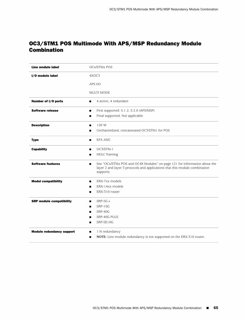
OC3/STM1 POS Multimode With APS/MSP Redundancy ModuleCombination
OCx/STMx POSLine module label
4XOC3
APS I/O
MULTI MODE
I/O module label
■ 4 active, 4 redundantNumber of I/O ports
■ First supported: 5.1.2, 5.2.0 (APS/MSP)
■ Final supported: Not applicable
Software release
■ 120 W
■ Unchannelized, concatenated OC3/STM1 for POS
Description
■ EFA ASICType
■ OC3/STM-1
■ HDLC framing
Capability
■ See “OCx/STMx POS and OC48 Modules” on page 121 for information about thelayer 2 and layer 3 protocols and applications that this module combinationsupports.
Software features
■ ERX-7xx models
■ ERX-14xx models
■ ERX-310 router
Model compatibility
■ SRP-5G+
■ SRP-10G
■ SRP-40G
■ SRP-40G PLUS
■ SRP-SE10G
SRP module compatibility
■ 1:N redundancy
■ NOTE: Line module redundancy is not supported on the ERX-310 router.
Module redundancy support
OC3/STM1 POS Multimode With APS/MSP Redundancy Module Combination ■ 65
OC3/STM1 POS Multimode With APS/MSP Redundancy Module Combination

■ LC full duplex
■ Tx power:
■ min: –19 dBm
■ max: –14 dBm
■ Center wavelength: 1310 nm
■ Rx input power:
■ min: –30 dBm
■ max: –14 dBm
■ Rated for 2 km (1.2 miles) over 62.5-micron core cable with an optical loss of 0–9dB or 50-micron core cable with an optical loss of 7 dB
■ See ERX Hardware Guide, Chapter 5, Cabling ERX Routers for more information.
Cables and connectors
■ See “Module LEDs” on page 133.LEDs
■ See Monitoring SONET/SDH Interfaces in JUNOSe Physical Layer Configuration Guide,Chapter 3, Configuring Unchannelized OCx/STMx Interfaces.
Alarms, errors, and events
66 ■ OC3/STM1 POS Multimode With APS/MSP Redundancy Module Combination
ERX 9.3.x Module Guide

OC3/STM1 POS Single-Mode Intermediate Reach Without APS/MSPRedundancy Module Combination
OCx/STMx POSLine module label
OC3-4 I/O
SINGLE MODE
I/O module label
■ 4Number of I/O ports
■ First supported: 2.0.0
■ Final supported: Not applicable
Software release
■ 120 W
■ Unchannelized, concatenated OC3/STM1 for POS
Description
■ EFA ASICType
■ OC3/STM1
■ HDLC framing
Capability
■ See “OCx/STMx POS and OC48 Modules” on page 121 for information about thelayer 2 and layer 3 protocols and applications that this module combinationsupports.
Software features
■ ERX-7xx models
■ ERX-14xx models
■ ERX-310 router
Model compatibility
■ SRP-5G+
■ SRP-10G
■ SRP-40G
■ SRP-40G PLUS
■ SRP-SE10G
SRP module compatibility
■ 1:N redundancy
■ NOTE: Line module redundancy is not supported on the ERX-310 router.
Module redundancy support
■ SC full duplex
■ Tx power:
■ min: –15 dBm
■ max: –8 dBm
■ Center wavelength: 1310 nm
■ Rx input power:
■ min: –31 dBm
■ max: –8 dBm
■ Rated for 15 km (9.3 miles) of 9-micron core cable
■ See ERX Hardware Guide, Chapter 5, Cabling ERX Routers for more information.
Cables and connectors
OC3/STM1 POS Single-Mode Intermediate Reach Without APS/MSP Redundancy Module Combination ■ 67
OC3/STM1 POS Single-Mode Intermediate Reach Without APS/MSP Redundancy Module Combination

■ See “Module LEDs” on page 133.LEDs
■ See Monitoring SONET/SDH Interfaces in JUNOSe Physical Layer ConfigurationGuide, Chapter 3, Configuring Unchannelized OCx/STMx Interfaces.
Alarms, errors, and events
68 ■ OC3/STM1 POS Single-Mode Intermediate Reach Without APS/MSP Redundancy Module Combination
ERX 9.3.x Module Guide

OC3/STM1 POS Single-Mode Intermediate Reach With APS/MSPRedundancy Module Combination
OCx/STMx POSLine module label
4XOC3
APS I/O
SINGLE MODE
I/O module label
■ 4 active, 4 redundantNumber of I/O ports
■ First supported: 5.1.2, 5.2.0 (APS/MSP)
■ Final supported: Not applicable
Software release
■ 120 W
■ Unchannelized, concatenated OC3/STM1 for POS
Description
■ EFA ASICType
■ OC3/STM1
■ HDLC framing
Capability
■ See “OCx/STMx POS and OC48 Modules” on page 121 for information about thelayer 2 and layer 3 protocols and applications that this module combinationsupports.
Software features
■ ERX-7xx models
■ ERX-14xx models
■ ERX-310 router
Model compatibility
■ SRP-5G+
■ SRP-10G
■ SRP-40G
■ SRP-40G PLUS
■ SRP-SE10G
SRP module compatibility
■ 1:N redundancy
■ NOTE: Line module redundancy is not supported on the ERX-310 router.
Module redundancy support
OC3/STM1 POS Single-Mode Intermediate Reach With APS/MSP Redundancy Module Combination ■ 69
OC3/STM1 POS Single-Mode Intermediate Reach With APS/MSP Redundancy Module Combination

■ LC full duplex
■ Tx power:
■ min: –15 dBm
■ max: –8 dBm
■ Center wavelength: 1310 nm
■ Rx input power:
■ min: –31 dBm
■ max: –8 dBm
■ Rated for 15 km (9.3 miles) of 9-micron core cable
■ See ERX Hardware Guide, Chapter 5, Cabling ERX Routers for more information.
Cables and connectors
■ See “Module LEDs” on page 133.LEDs
■ See Monitoring SONET/SDH Interfaces in JUNOSe Physical Layer ConfigurationGuide, Chapter 3, Configuring Unchannelized OCx/STMx Interfaces.
Alarms, errors, and events
70 ■ OC3/STM1 POS Single-Mode Intermediate Reach With APS/MSP Redundancy Module Combination
ERX 9.3.x Module Guide

OC3/STM1 POS Single-Mode Long Reach Module Combination
OCx/STMx POSLine module label
OC3-4 I/O
LONG HAUL
I/O module label
■ 4Number of I/O ports
■ First supported: 2.0.0
■ Final supported: Not applicable
Software release
■ 120 W
■ Unchannelized, concatenated OC3/STM1 for POS
Description
■ EFA ASICType
■ OC3/STM1
■ HDLC framing
Capability
■ See “OCx/STMx POS and OC48 Modules” on page 121 for information about thelayer 2 and layer 3 protocols and applications that this module combinationsupports.
Software features
■ ERX-7xx models
■ ERX-14xx models
■ ERX-310 router
Model compatibility
■ SRP-5G+
■ SRP-10G
■ SRP-40G
■ SRP-40G PLUS
■ SRP-SE10G
SRP module compatibility
■ 1:N redundancy
■ NOTE: Line module redundancy is not supported on the ERX-310 router.
Module redundancy support
■ SC full duplex
■ Tx power:
■ min: –5.0 dBm
■ max: 0 dBm
■ Center wavelength: 1310 nm
■ Rx input power:
■ min: –34 dBm
■ max: –7 dBm
■ Fiber type: 9-micron core
■ Rated for 40 km (24.8 miles) of 9-micron core cable
■ See ERX Hardware Guide, Chapter 5, Cabling ERX Routers for more information.
Cables and connectors
OC3/STM1 POS Single-Mode Long Reach Module Combination ■ 71
OC3/STM1 POS Single-Mode Long Reach Module Combination

■ See “Module LEDs” on page 133.LEDs
■ See Monitoring SONET/SDH Interfaces in JUNOSe Physical Layer ConfigurationGuide, Chapter 3, Configuring Unchannelized OCx/STMx Interfaces.
Alarms, errors, and events
72 ■ OC3/STM1 POS Single-Mode Long Reach Module Combination
ERX 9.3.x Module Guide

OC12/STM4 ATM Multimode Without APS/MSP Redundancy ModuleCombination (256-MB Memory)
OCx/STMx ATM or OCx/STMx /DS3-ATMLine module label
OC12 STM4 I/O
MULTI MODE
I/O module label
■ 1Number of I/O ports
■ First supported: 5.0.0, 5.3.0 or a higher-numbered release
■ Final supported: Not applicable
Software release
■ 130 W
■ 256 MB of memory
■ The 128-MB version has reached end-of-life.
■ Unchannelized, concatenated OC12/STM4 for ATM
Description
■ EFA ASICType
■ OC12/STM4
■ ATM/AAL5
Capability
■ See “OCx/STMx ATM Modules” on page 119 for information about the layer 2 andlayer 3 protocols and applications that this module combination supports.
Software features
■ ERX-7xx models
■ ERX-14xx models
■ ERX-310 router
Model compatibility
■ SRP-5G+
■ SRP-10G
■ SRP-40G
■ SRP-40G PLUS
■ SRP-SE10G
SRP module compatibility
■ 1:N redundancy
■ NOTE: Line module redundancy is not supported on the ERX-310 router.
Module redundancy support
OC12/STM4 ATM Multimode Without APS/MSP Redundancy Module Combination (256-MB Memory) ■ 73
OC12/STM4 ATM Multimode Without APS/MSP Redundancy Module Combination (256-MB Memory)

■ SC full duplex
■ Tx power:
■ min: –19 dBm
■ max: –14 dBm
■ Center wavelength: 1310 nm
■ Rx input power:
■ min: –30 dBm
■ max: –14 dBm
■ Rated for 2 km (1.2 miles) over 62.5-micron core cable with an optical loss of 0–9dB or 50-micron core cable with an optical loss of 7 dB
■ See ERX Hardware Guide, Chapter 5, Cabling ERX Routers for more information.
Cables and connectors
■ See “Module LEDs” on page 133.LEDs
■ See Monitoring SONET/SDH Interfaces in JUNOSe Physical Layer Configuration Guide,Chapter 3, Configuring Unchannelized OCx/STMx Interfaces.
Alarms, errors, and events
74 ■ OC12/STM4 ATM Multimode Without APS/MSP Redundancy Module Combination (256-MB Memory)
ERX 9.3.x Module Guide

OC12/STM4 ATM Multimode With APS/MSP Redundancy ModuleCombination
OCx/STMx ATM or OCx/STMx /DS3-ATMLine module label
OC12 STM4 APS
MULTI MODE
I/O module label
■ 1 active, 1 redundantNumber of I/O ports
■ First supported: 2.0.0 (128 MB), 5.0.0 (256 MB)
■ Final supported: Not applicable
■ The OCx/STMx ATM line module or the OCx/STMx /DS3-ATM line module must havea minimum of 256 MB of memory to be used with JUNOSe Release 5.3.0 or ahigher-numbered release.
Software release
■ 130 W
■ Can use either the 128-MB OCx/STMx ATM line module or the 256-MB OCx/STMx/DS3-ATM line module.
■ Unchannelized, concatenated OC12/STM4 for ATM
Description
■ EFA ASICType
■ OC12/STM4
■ ATM/AAL5
Capability
■ See “OCx/STMx ATM Modules” on page 119 for information about the layer 2 andlayer 3 protocols and applications that this module combination supports.
Software features
■ ERX-7xx models
■ ERX-14xx models
■ ERX-310 router
Model compatibility
■ SRP-5G+
■ SRP-10G
■ SRP-40G
■ SRP-40G PLUS
■ SRP-SE10G
SRP module compatibility
■ 1:N redundancy
■ NOTE: Line module redundancy is not supported on the ERX-310 router.
Module redundancy support
OC12/STM4 ATM Multimode With APS/MSP Redundancy Module Combination ■ 75
OC12/STM4 ATM Multimode With APS/MSP Redundancy Module Combination
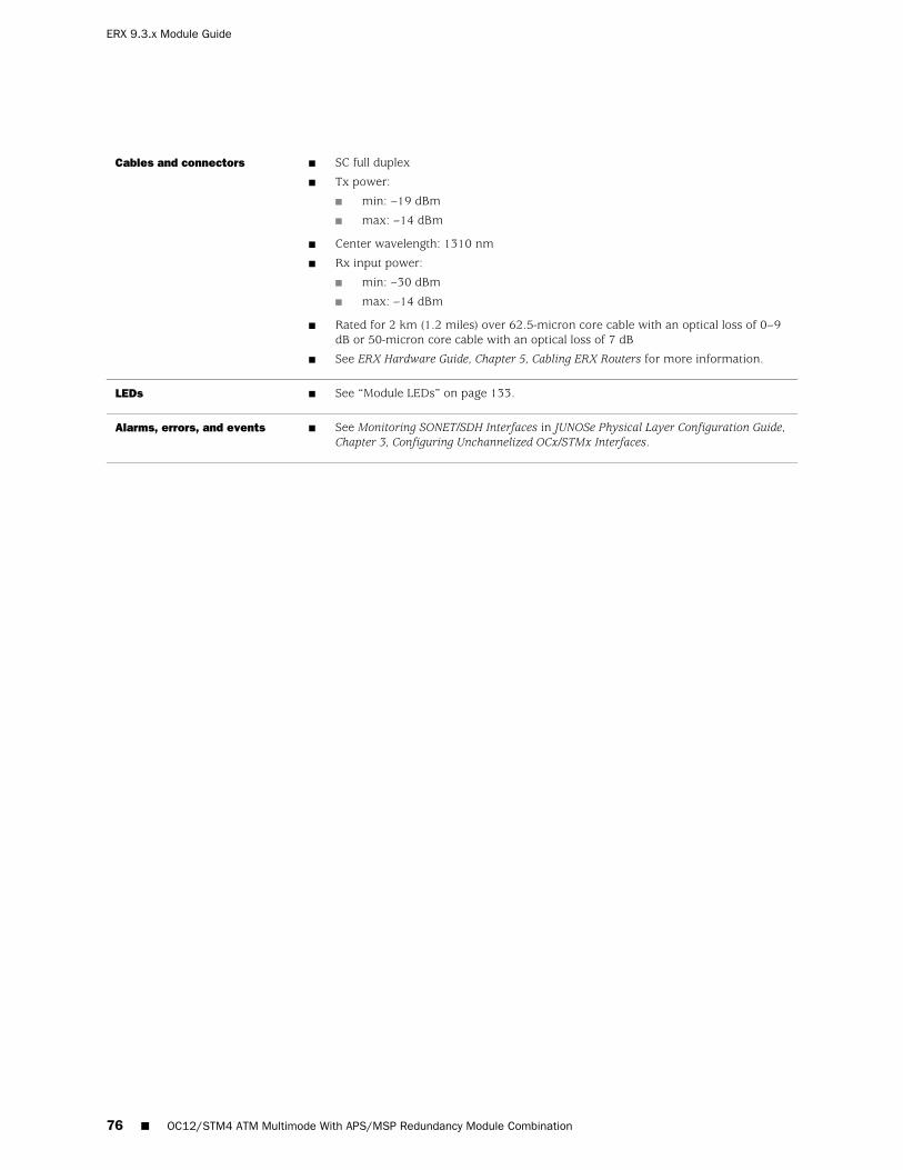
■ SC full duplex
■ Tx power:
■ min: –19 dBm
■ max: –14 dBm
■ Center wavelength: 1310 nm
■ Rx input power:
■ min: –30 dBm
■ max: –14 dBm
■ Rated for 2 km (1.2 miles) over 62.5-micron core cable with an optical loss of 0–9dB or 50-micron core cable with an optical loss of 7 dB
■ See ERX Hardware Guide, Chapter 5, Cabling ERX Routers for more information.
Cables and connectors
■ See “Module LEDs” on page 133.LEDs
■ See Monitoring SONET/SDH Interfaces in JUNOSe Physical Layer Configuration Guide,Chapter 3, Configuring Unchannelized OCx/STMx Interfaces.
Alarms, errors, and events
76 ■ OC12/STM4 ATM Multimode With APS/MSP Redundancy Module Combination
ERX 9.3.x Module Guide

OC12/STM4 ATM Single-Mode Intermediate Reach Without APS/MSPRedundancy Module Combination (256-MB Memory)
OCx/STMx ATM or OCx/STMx /DS3-ATMLine module label
OC12 STM4 I/O
SINGLE MODE
I/O module label
■ 1Number of I/O ports
■ First supported: 5.0.0, 5.3.0 or a higher-numbered release
■ Final supported: Not applicable
Software release
■ 130 W
■ 256 MB of memory
■ The 128-MB version has reached end-of-life.
■ Unchannelized, concatenated OC12/STM4 for ATM
Description
■ EFA ASICType
■ OC12/STM4
■ ATM/AAL5
Capability
■ See “OCx/STMx ATM Modules” on page 119 for information about the layer 2 andlayer 3 protocols and applications that this module combination supports.
Software features
■ ERX-7xx models
■ ERX-14xx models
■ ERX-310 router
Model compatibility
■ SRP-5G+
■ SRP-10G
■ SRP-40G
■ SRP-40G PLUS
■ SRP-SE10G
SRP module compatibility
■ 1:N redundancy
■ NOTE: Line module redundancy is not supported on the ERX-310 router.
Module redundancy support
OC12/STM4 ATM Single-Mode Intermediate Reach Without APS/MSP Redundancy Module Combination (256-MB Memory) ■ 77
OC12/STM4 ATM Single-Mode Intermediate Reach Without APS/MSP Redundancy Module Combination (256-MB Memory)
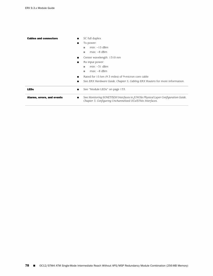
■ SC full duplex
■ Tx power:
■ min: –15 dBm
■ max: –8 dBm
■ Center wavelength: 1310 nm
■ Rx input power:
■ min: –31 dBm
■ max: –8 dBm
■ Rated for 15 km (9.3 miles) of 9-micron core cable
■ See ERX Hardware Guide, Chapter 5, Cabling ERX Routers for more information.
Cables and connectors
■ See “Module LEDs” on page 133.LEDs
■ See Monitoring SONET/SDH Interfaces in JUNOSe Physical Layer Configuration Guide,Chapter 3, Configuring Unchannelized OCx/STMx Interfaces.
Alarms, errors, and events
78 ■ OC12/STM4 ATM Single-Mode Intermediate Reach Without APS/MSP Redundancy Module Combination (256-MB Memory)
ERX 9.3.x Module Guide

OC12/STM4 ATM Single-Mode Intermediate Reach With APS/MSPRedundancy Module Combination
OCx/STMx ATM or OCx/STMx /DS3-ATMLine module label
OC12 STM4 APS
SINGLE MODE
I/O module label
■ 1 active, 1 redundantNumber of I/O ports
■ First supported: 2.0.0 (128 MB), 5.0.0 (256 MB)
■ Final supported: Not applicable
■ The OCx/STMx ATM line module or the OCx/STMx/DS3-ATM line module must havea minimum of 256 MB of memory to be used with JUNOSe Release 5.3.0 or ahigher-numbered release.
Software release
■ 130 W
■ Can use either the 128-MB OCx/STMx ATM line module or the 256-MBOCx/STMx/DS3-ATM line module.
■ Unchannelized, concatenated OC12/STM4 for ATM
Description
■ EFA ASICType
■ OC12/STM4
■ ATM/AAL5
Capability
■ See “OCx/STMx ATM Modules” on page 119 for information about the layer 2 andlayer 3 protocols and applications that this module combination supports.
Software features
■ ERX-7xx models
■ ERX-14xx models
■ ERX-310 router
Model compatibility
■ SRP-5G+
■ SRP-10G
■ SRP-40G
■ SRP-40G PLUS
■ SRP-SE10G
SRP module compatibility
■ 1:N redundancy
■ NOTE: Line module redundancy is not supported on the ERX-310 router.
Module redundancy support
OC12/STM4 ATM Single-Mode Intermediate Reach With APS/MSP Redundancy Module Combination ■ 79
OC12/STM4 ATM Single-Mode Intermediate Reach With APS/MSP Redundancy Module Combination

■ SC full duplex
■ Tx power:
■ min: –15 dBm
■ max: –8 dBm
■ Center wavelength: 1310 nm
■ Rx input power:
■ min: –31 dBm
■ max: –8 dBm
■ Rated for 15 km (9.3 miles) of 9-micron core cable
■ See ERX Hardware Guide, Chapter 5, Cabling ERX Routers for more information.
Cables and connectors
■ See “Module LEDs” on page 133.LEDs
■ See Monitoring SONET/SDH Interfaces in JUNOSe Physical Layer Configuration Guide,Chapter 3, Configuring Unchannelized OCx/STMx Interfaces.
Alarms, errors, and events
80 ■ OC12/STM4 ATM Single-Mode Intermediate Reach With APS/MSP Redundancy Module Combination
ERX 9.3.x Module Guide

OC12/STM4 ATM Single-Mode Long Reach Without APS/MSPRedundancy Module Combination (256-MB Memory)
OCx/STMx ATM or OCx/STMx /DS3-ATMLine module label
OC12 STM4 I/O
LONG HAUL
I/O module label
■ 1Number of I/O ports
■ First supported: 5.0.0, 5.3.0 or a higher-numbered release
■ Final supported: Not applicable
Software release
■ 130 W
■ 256 MB of memory
■ The 128-MB version has reached end-of-life.
■ Unchannelized, concatenated OC12/STM4 for ATM
Description
■ EFA ASICType
■ OC12/STM4
■ ATM/AAL5
Capability
■ See “OCx/STMx ATM Modules” on page 119 for information about the layer 2 andlayer 3 protocols and applications that this module combination supports.
Software features
■ ERX-7xx models
■ ERX-14xx models
■ ERX-310 router
Model compatibility
■ SRP-5G+
■ SRP-10G
■ SRP-40G
■ SRP-40G PLUS
■ SRP-SE10G
SRP module compatibility
■ 1:N redundancy
■ NOTE: Line module redundancy is not supported on the ERX-310 router.
Module redundancy support
OC12/STM4 ATM Single-Mode Long Reach Without APS/MSP Redundancy Module Combination (256-MB Memory) ■ 81
OC12/STM4 ATM Single-Mode Long Reach Without APS/MSP Redundancy Module Combination (256-MB Memory)

■ SC full duplex
■ Tx power:
■ min: –5.0 dBm
■ max: 0 dBm
■ Center wavelength: 1310 nm
■ Rx input power:
■ min: –34 dBm
■ max: –7 dBm
■ Fiber type: 9-micron core
■ Rated for 40 km (24.8 miles) of 9-micron core cable
■ See ERX Hardware Guide, Chapter 5, Cabling ERX Routers for more information.
Cables and connectors
■ See “Module LEDs” on page 133.LEDs
■ See Monitoring SONET/SDH Interfaces in JUNOSe Physical Layer Configuration Guide,Chapter 3, Configuring Unchannelized OCx/STMx Interfaces.
Alarms, errors, and events
82 ■ OC12/STM4 ATM Single-Mode Long Reach Without APS/MSP Redundancy Module Combination (256-MB Memory)
ERX 9.3.x Module Guide

OC12/STM4 ATM Single-Mode Long Reach With APS/MSP RedundancyModule Combination
OCx/STMx ATM or OCx/STMx /DS3-ATMLine module label
OC12 STM4 APS
LONG HAUL
I/O module label
■ 1 active, 1 redundantNumber of I/O ports
■ First supported: 2.0.0 (128 MB), 5.0.0 (256 MB)
■ Final supported: Not applicable
■ The OCx/STMx ATM line module or the OCx/STMx /DS3-ATM line module must havea minimum of 256 MB of memory to be used with JUNOSe Release 5.3.0 or ahigher-numbered release.
Software release
■ 130 W
■ Can use either the 128-MB OCx/STMx ATM line module or the 256-MB OCx/STMx/DS3-ATM line module.
■ Unchannelized, concatenated OC12/STM4 for ATM
Description
■ EFA ASICType
■ OC12/STM4
■ ATM/AAL5
Capability
■ See “OCx/STMx ATM Modules” on page 119 for information about the layer 2 andlayer 3 protocols and applications that this module combination supports.
Software features
■ ERX-7xx models
■ ERX-14xx models
■ ERX-310 router
Model compatibility
■ SRP-5G+
■ SRP-10G
■ SRP-40G
■ SRP-40G PLUS
■ SRP-SE10G
SRP module compatibility
■ 1:N redundancy
■ NOTE: Line module redundancy is not supported on the ERX-310 router.
Module redundancy support
OC12/STM4 ATM Single-Mode Long Reach With APS/MSP Redundancy Module Combination ■ 83
OC12/STM4 ATM Single-Mode Long Reach With APS/MSP Redundancy Module Combination

■ SC full duplex
■ Tx power:
■ min: –5.0 dBm
■ max: 0 dBm
■ Center wavelength: 1310 nm
■ Rx input power:
■ min: –34 dBm
■ max: –7 dBm
■ Fiber type: 9-micron core
■ Rated for 40 km (24.8 miles) of 9-micron core cable
■ See ERX Hardware Guide, Chapter 5, Cabling ERX Routers for more information.
Cables and connectors
■ See “Module LEDs” on page 133.LEDs
■ See Monitoring SONET/SDH Interfaces in JUNOSe Physical Layer Configuration Guide,Chapter 3, Configuring Unchannelized OCx/STMx Interfaces.
Alarms, errors, and events
84 ■ OC12/STM4 ATM Single-Mode Long Reach With APS/MSP Redundancy Module Combination
ERX 9.3.x Module Guide

OC12/STM4 POS Multimode Without APS/MSP Redundancy ModuleCombination
OCx/STMx POSLine module label
OC12 STM4 I/O
MULTI MODE
I/O module label
■ 1Number of I/O ports
■ First supported: 2.0.0
■ Final supported: Not applicable
Software release
■ 120 W
■ Unchannelized, concatenated OC12/STM4 for POS
Description
■ EFA ASICType
■ OC12/STM4
■ HDLC framing
Capability
■ See “OCx/STMx POS and OC48 Modules” on page 121 for information about thelayer 2 and layer 3 protocols and applications that this module combinationsupports.
Software features
■ ERX-7xx models
■ ERX-14xx models
■ ERX-310 router
Model compatibility
■ SRP-5G+
■ SRP-10G
■ SRP-40G
■ SRP-40G PLUS
■ SRP-SE10G
SRP module compatibility
■ 1:N redundancy
■ NOTE: Line module redundancy is not supported on the ERX-310 router.
Module redundancy support
OC12/STM4 POS Multimode Without APS/MSP Redundancy Module Combination ■ 85
OC12/STM4 POS Multimode Without APS/MSP Redundancy Module Combination

■ SC full duplex
■ Tx power:
■ min: –19 dBm
■ max: –14 dBm
■ Center wavelength: 1310 nm
■ Rx input power:
■ min: –30 dBm
■ max: –14 dBm
■ Rated for 2 km (1.2 miles) over 62.5-micron core cable with an optical loss of0–9 dB or 50-micron core cable with an optical loss of 7 dB
■ See ERX Hardware Guide, Chapter 5, Cabling ERX Routers for more information.
Cables and connectors
■ See “Module LEDs” on page 133.LEDs
■ See Monitoring SONET/SDH Interfaces in JUNOSe Physical Layer Configuration Guide,Chapter 3, Configuring Unchannelized OCx/STMx Interfaces.
Alarms, errors, and events
86 ■ OC12/STM4 POS Multimode Without APS/MSP Redundancy Module Combination
ERX 9.3.x Module Guide
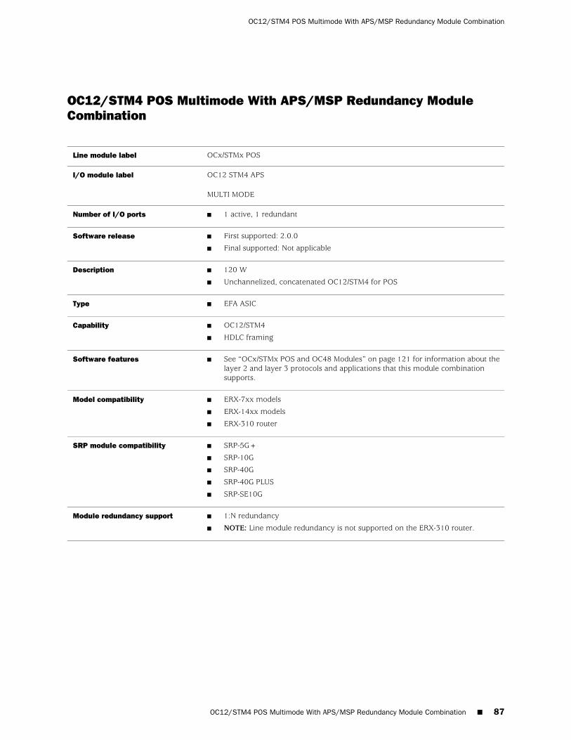
OC12/STM4 POS Multimode With APS/MSP Redundancy ModuleCombination
OCx/STMx POSLine module label
OC12 STM4 APS
MULTI MODE
I/O module label
■ 1 active, 1 redundantNumber of I/O ports
■ First supported: 2.0.0
■ Final supported: Not applicable
Software release
■ 120 W
■ Unchannelized, concatenated OC12/STM4 for POS
Description
■ EFA ASICType
■ OC12/STM4
■ HDLC framing
Capability
■ See “OCx/STMx POS and OC48 Modules” on page 121 for information about thelayer 2 and layer 3 protocols and applications that this module combinationsupports.
Software features
■ ERX-7xx models
■ ERX-14xx models
■ ERX-310 router
Model compatibility
■ SRP-5G+
■ SRP-10G
■ SRP-40G
■ SRP-40G PLUS
■ SRP-SE10G
SRP module compatibility
■ 1:N redundancy
■ NOTE: Line module redundancy is not supported on the ERX-310 router.
Module redundancy support
OC12/STM4 POS Multimode With APS/MSP Redundancy Module Combination ■ 87
OC12/STM4 POS Multimode With APS/MSP Redundancy Module Combination
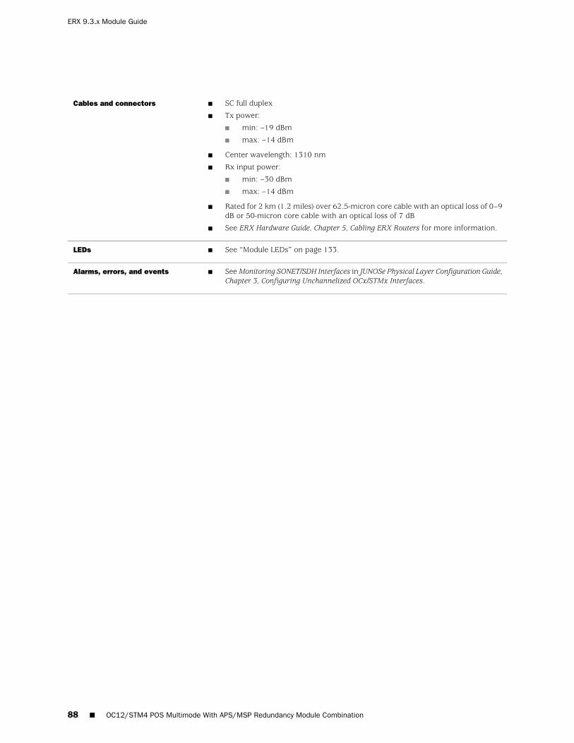
■ SC full duplex
■ Tx power:
■ min: –19 dBm
■ max: –14 dBm
■ Center wavelength: 1310 nm
■ Rx input power:
■ min: –30 dBm
■ max: –14 dBm
■ Rated for 2 km (1.2 miles) over 62.5-micron core cable with an optical loss of 0–9dB or 50-micron core cable with an optical loss of 7 dB
■ See ERX Hardware Guide, Chapter 5, Cabling ERX Routers for more information.
Cables and connectors
■ See “Module LEDs” on page 133.LEDs
■ See Monitoring SONET/SDH Interfaces in JUNOSe Physical Layer Configuration Guide,Chapter 3, Configuring Unchannelized OCx/STMx Interfaces.
Alarms, errors, and events
88 ■ OC12/STM4 POS Multimode With APS/MSP Redundancy Module Combination
ERX 9.3.x Module Guide

OC12/STM4 POS Single-Mode Intermediate Reach Without APS/MSPRedundancy Module Combination
OCx/STMx POSLine module label
OC12 STM4 I/O
SINGLE MODE
I/O module label
■ 1Number of I/O ports
■ First supported: 2.0.0
■ Final supported: Not applicable
Software release
■ 120 W
■ Unchannelized, concatenated OC12/STM4 for POS
Description
■ EFA ASICType
■ OC12/STM4
■ HDLC framing
Capability
■ See “OCx/STMx POS and OC48 Modules” on page 121 for information about thelayer 2 and layer 3 protocols and applications that this module combinationsupports.
Software features
■ ERX-7xx models
■ ERX-14xx models
■ ERX-310 router
Model compatibility
■ SRP-5G+
■ SRP-10G
■ SRP-40G
■ SRP-40G PLUS
■ SRP-SE10G
SRP module compatibility
■ 1:N redundancy
■ NOTE: Line module redundancy is not supported on the ERX-310 router.
Module redundancy support
■ SC full duplex
■ Tx power:
■ min: –15 dBm
■ max: –8 dBm
■ Center wavelength: 1310 nm
■ Rx input power:
■ min: –31 dBm
■ max: –8 dBm
■ Rated for 15 km (9.3 miles) of 9-micron core cable
■ See ERX Hardware Guide, Chapter 5, Cabling ERX Routers for more information.
Cables and connectors
OC12/STM4 POS Single-Mode Intermediate Reach Without APS/MSP Redundancy Module Combination ■ 89
OC12/STM4 POS Single-Mode Intermediate Reach Without APS/MSP Redundancy Module Combination

■ See “Module LEDs” on page 133.LEDs
■ See Monitoring SONET/SDH Interfaces in JUNOSe Physical Layer ConfigurationGuide, Chapter 3, Configuring Unchannelized OCx/STMx Interfaces.
Alarms, errors, and events
90 ■ OC12/STM4 POS Single-Mode Intermediate Reach Without APS/MSP Redundancy Module Combination
ERX 9.3.x Module Guide

OC12/STM4 POS Single-Mode Intermediate Reach With APS/MSPRedundancy Module Combination
OCx/STMx POSLine module label
OC12 STM4 APS
SINGLE MODE
I/O module label
■ 1 active, 1 redundantNumber of I/O ports
■ First supported: 2.0.0
■ Final supported: Not applicable
Software release
■ 120 W
■ Unchannelized, concatenated OC12/STM4 for POS
Description
■ EFA ASICType
■ OC12/STM4
■ HDLC framing
Capability
■ See “OCx/STMx POS and OC48 Modules” on page 121 for information about thelayer 2 and layer 3 protocols and applications that this module combinationsupports.
Software features
■ ERX-7xx models
■ ERX-14xx models
■ ERX-310 router
Model compatibility
■ SRP-5G+
■ SRP-10G
■ SRP-40G
■ SRP-40G PLUS
■ SRP-SE10G
SRP module compatibility
■ 1:N redundancy
■ NOTE: Line module redundancy is not supported on the ERX-310 router.
Module redundancy support
■ SC full duplex
■ Tx power:
■ min: –15 dBm
■ max: –8 dBm
■ Center wavelength: 1310 nm
■ Rx input power:
■ min: –31 dBm
■ max: –8 dBm
■ Rated for 15 km (9.3 miles) of 9-micron core cable
■ See ERX Hardware Guide, Chapter 5, Cabling ERX Routers for more information.
Cables and connectors
OC12/STM4 POS Single-Mode Intermediate Reach With APS/MSP Redundancy Module Combination ■ 91
OC12/STM4 POS Single-Mode Intermediate Reach With APS/MSP Redundancy Module Combination

■ See “Module LEDs” on page 133.LEDs
■ See Monitoring SONET/SDH Interfaces in JUNOSe Physical Layer ConfigurationGuide, Chapter 3, Configuring Unchannelized OCx/STMx Interfaces.
Alarms, errors, and events
92 ■ OC12/STM4 POS Single-Mode Intermediate Reach With APS/MSP Redundancy Module Combination
ERX 9.3.x Module Guide

OC12/STM4 POS Single-Mode Long Reach Without APS/MSPRedundancy Module Combination
OCx/STMx POSLine module label
OC12 STM4 I/O
LONG HAUL
I/O module label
■ 1Number of I/O ports
■ First supported: 2.0.0
■ Final supported: Not applicable
Software release
■ 120 W
■ Unchannelized, concatenated OC12/STM4 for POS
Description
■ EFA ASICType
■ OC12/STM4
■ HDLC framing
Capability
■ See “OCx/STMx POS and OC48 Modules” on page 121 for information about thelayer 2 and layer 3 protocols and applications that this module combinationsupports.
Software features
■ ERX-7xx models
■ ERX-14xx models
■ ERX-310 router
Model compatibility
■ SRP-5G+
■ SRP-10G
■ SRP-40G
■ SRP-40G PLUS
■ SRP-SE10G
SRP module compatibility
■ 1:N redundancy
■ NOTE: Line module redundancy is not supported on the ERX-310 router.
Module redundancy support
■ SC full duplex
■ Tx power:
■ min: –5.0 dBm
■ max: 0 dBm
■ Center wavelength: 1310 nm
■ Rx input power:
■ min: –34 dBm
■ max: –7 dBm
■ Rated for 40 km (24.8 miles) of 9-micron core cable
■ See ERX Hardware Guide, Chapter 5, Cabling ERX Routers for more information.
Cables and connectors
OC12/STM4 POS Single-Mode Long Reach Without APS/MSP Redundancy Module Combination ■ 93
OC12/STM4 POS Single-Mode Long Reach Without APS/MSP Redundancy Module Combination

■ See “Module LEDs” on page 133.LEDs
■ See Monitoring SONET/SDH Interfaces in JUNOSe Physical Layer ConfigurationGuide, Chapter 3, Configuring Unchannelized OCx/STMx Interfaces.
Alarms, errors, and events
94 ■ OC12/STM4 POS Single-Mode Long Reach Without APS/MSP Redundancy Module Combination
ERX 9.3.x Module Guide

OC12/STM4 POS Single-Mode Long Reach With APS/MSP RedundancyModule Combination
OCx/STMx POSLine module label
OC12 STM4 APS
LONG HAUL
I/O module label
■ 1 active, 1 redundantNumber of I/O ports
■ First supported: 2.0.0
■ Final supported: Not applicable
Software release
■ 120 W
■ Unchannelized, concatenated OC12/STM4 for POS
Description
■ EFA ASICType
■ OC12/STM4
■ HDLC framing
Capability
■ See “OCx/STMx POS and OC48 Modules” on page 121 for information about thelayer 2 and layer 3 protocols and applications that this module combinationsupports.
Software features
■ ERX-7xx models
■ ERX-14xx models
■ ERX-310 router
Model compatibility
■ SRP-5G+
■ SRP-10G
■ SRP-40G
■ SRP-40G PLUS
■ SRP-SE10G
SRP module compatibility
■ 1:N redundancy
■ NOTE: Line module redundancy is not supported on the ERX-310 router.
Module redundancy support
■ SC full duplex
■ Tx power:
■ min: –5.0 dBm
■ max: 0 dBm
■ Center wavelength: 1310 nm
■ Rx input power:
■ min: –34 dBm
■ max: –7 dBm
■ Rated for 40 km (24.8 miles) of 9-micron core cable
■ See ERX Hardware Guide, Chapter 5, Cabling ERX Routers for more information.
Cables and connectors
OC12/STM4 POS Single-Mode Long Reach With APS/MSP Redundancy Module Combination ■ 95
OC12/STM4 POS Single-Mode Long Reach With APS/MSP Redundancy Module Combination

■ See “Module LEDs” on page 133.LEDs
■ See Monitoring SONET/SDH Interfaces in JUNOSe Physical Layer ConfigurationGuide, Chapter 3, Configuring Unchannelized OCx/STMx Interfaces.
Alarms, errors, and events
96 ■ OC12/STM4 POS Single-Mode Long Reach With APS/MSP Redundancy Module Combination
ERX 9.3.x Module Guide

OC48/STM16 POS Single-Mode Short Reach Module Combination
OC48Line module label
OC48 FRAME APSI/O module label
■ 1Number of I/O ports
■ First supported: 4.1.x
■ Final supported: Not applicable
Software release
■ 120 W
■ Unchannelized, concatenated OC48/STM16 for POS
Description
■ FFA ASICType
■ OC48/STM16
■ HDLC framing
Capability
■ See “OCx/STMx POS and OC48 Modules” on page 121 for information aboutthe layer 2 and layer 3 protocols and applications that this module combinationsupports.
Software features
■ ERX-1440 routerModel compatibility
■ SRP-40G
■ SRP-40G PLUS
SRP module compatibility
■ Not applicableModule redundancy support
■ LC full duplex connector
■ Transmit power:
■ min: –10 dBm
■ max: –3 dBm
■ Center wavelength: 1310 nm
■ Receive input power:
■ min: –18 dBm
■ max: –3 dBm
■ Rated for 2 km (1.2 miles) of 9-micron core cable
■ See ERX Hardware Guide, Chapter 5, Cabling ERX Routers for more information.
Cables and connectors
■ See “Module LEDs” on page 133.LEDs
■ See Monitoring SONET/SDH Interfaces in JUNOSe Physical Layer ConfigurationGuide, Chapter 3, Configuring Unchannelized OCx/STMx Interfaces.
Alarms, errors, and events
OC48/STM16 POS Single-Mode Short Reach Module Combination ■ 97
OC48/STM16 POS Single-Mode Short Reach Module Combination

Service Module (SM) Module Combination
SERVICE MODULELine module label
No I/O moduleI/O module label
■ Not applicableNumber of I/O ports
■ First supported: 5.1.0
■ Final supported: Not applicable
Software release
■ 130 W
■ Tunnel Service for IP tunnels, L2F tunnels, and LNS termination
Description
■ EFA ASICType
■ IP tunnels
■ LNS termination
■ Network Address Translation
■ Stateful firewall
Capability
■ See “Service Modules” on page 124 for information about the layer 2 and layer3 protocols and applications that this module combination supports.
Software features
■ ERX-7xx models
■ ERX-14xx models
■ ERX-310 router
Model compatibility
■ SRP-5G+
■ SRP-10G
■ SRP-40G
■ SRP-40G PLUS
■ SRP-SE10G
SRP module compatibility
■ Multiple SMs provide redundancy.
■ See JUNOSe Physical Layer Configuration Guide, Chapter 6, ManagingTunnel-Service and IPSec-Service Interfaces
Module redundancy support
■ Not applicableCables and connectors
■ See “Module LEDs” on page 133.LEDs
■ See Monitoring Tunnel-Service Interfaces in JUNOSe Physical Layer ConfigurationGuide, Chapter 6, Managing Tunnel-Service and IPSec-Service Interfaces.
Alarms, errors, and events
98 ■ Service Module (SM) Module Combination
ERX 9.3.x Module Guide

SRP-5G+ Module Combination (1-GB Memory)
SRP-5G+Line module label
SRP I/OI/O module label
■ 7Number of I/O ports
■ First supported: 4.1.3 or later 4.1.x release, 5.0.4 or later 5.0.x release, 5.1.2or higher-numbered release, 5.2.0
■ Final supported: Not applicable
Software release
■ 125 W
■ Switch route processor (5 Gbps)
■ Has a minimum of 1 GB of error checking and correction (ECC) memorywith a 1-GB nonvolatile storage (NVS) card.
■ The 512–MB version has reached end-of-life.
Description
■ Not applicableType
■ Ethernet (IEEE 802.3)
■ 10/100Base-T
■ RS-232
Capability
■ Not applicableSoftware features
■ ERX-705 routerModel compatibility
■ SRP-5G+SRP module compatibility
■ 1:1 redundancyModule redundancy support
■ Terminal blocks
■ BNC, 75–ohm
■ Wire wrap posts
■ RJ-45
■ RS-232 (DB-9)
■ See ERX Hardware Guide, Chapter 5, Cabling ERX Routers for moreinformation.
Cables and connectors
■ See “Module LEDs” on page 133.LEDs
■ See Monitoring Modules in JUNOSe System Basics Configuration Guide,Chapter 6, Managing Modules.
Alarms, errors, and events
SRP-5G+ Module Combination (1-GB Memory) ■ 99
SRP-5G+ Module Combination (1-GB Memory)

SRP-5G+ Module Combination (2-GB Memory)
SRP-5G+Line module label
SRP I/OI/O module label
■ 7Number of I/O ports
■ First supported: 4.1.3 or later 4.1.x release, 5.0.4 or later 5.0.x release, 5.1.2or higher-numbered release, 5.2.0
■ Final supported: Not applicable
Software release
■ 125 W
■ Switch route processor (5 Gbps)
■ Has a minimum of 2 GB of error checking and correction (ECC) memorywith a 1-GB nonvolatile storage (NVS) card.
■ The 512–MB version has reached end-of-life.
Description
■ Not applicableType
■ Ethernet (IEEE 802.3)
■ 10/100Base-T
■ RS-232
Capability
■ Not applicableSoftware features
■ ERX-705 routerModel compatibility
■ SRP-5G+SRP module compatibility
■ 1:1 redundancyModule redundancy support
■ Terminal blocks
■ BNC, 75–ohm
■ Wire wrap posts
■ RJ-45
■ RS-232 (DB-9)
■ See ERX Hardware Guide, Chapter 5, Cabling ERX Routers for moreinformation.
Cables and connectors
■ See “Module LEDs” on page 133.LEDs
■ See Monitoring Modules in JUNOSe System Basics Configuration Guide,Chapter 6, Managing Modules.
Alarms, errors, and events
100 ■ SRP-5G+ Module Combination (2-GB Memory)
ERX 9.3.x Module Guide

SRP-10G Module Combination (2-GB Memory)
SRP-10GLine module label
SRP I/OI/O module label
■ 7Number of I/O ports
■ First supported: 4.1.3 or later 4.1.x release, 5.0.4 or later 5.0.x release, 5.1.2or higher-numbered release, 5.2.0
■ Final supported: Not applicable
Software release
■ 125 W
■ Switch route processor (10 Gbps)
■ Has a minimum of 2 GB of error checking and correction (ECC) memory witha 1-GB nonvolatile storage (NVS) card.
■ The 512–MB version has reached end-of-life.
Description
■ Not applicableType
■ Ethernet (IEEE 802.3)
■ 10/100Base-T
■ RS-232
Capability
■ Not applicableSoftware features
■ ERX-710 router
■ ERX-1410 router
Model compatibility
■ SRP-10GSRP module compatibility
■ 1:1 redundancyModule redundancy support
■ Terminal blocks
■ BNC, 75–ohm
■ Wire wrap posts
■ RJ-45
■ RS-232 (DB-9)
■ See ERX Hardware Guide, Chapter 5, Cabling ERX Routers for more information.
Cables and connectors
■ See “Module LEDs” on page 133.LEDs
■ See Monitoring Modules in JUNOSe System Basics Configuration Guide,Chapter 6, Managing Modules.
Alarms, errors, and events
SRP-10G Module Combination (2-GB Memory) ■ 101
SRP-10G Module Combination (2-GB Memory)

SRP-40G PLUS Module Combination (2-GB Memory)
SRP-40G PLUSLine module label
SRP I/OI/O module label
■ 7Number of I/O ports
■ First supported: 4.0.0
■ Final supported: Not applicable
Software release
■ 210 W
■ Switch route processor (40 Gbps)
■ Has a minimum of 2 GB of error checking and correction (ECC) memorywith a 1-GB nonvolatile storage (NVS) card.
Description
■ Not applicableType
■ Ethernet (IEEE 802.3)
■ 10/100Base-T
■ RS-232
Capability
■ Not applicableSoftware features
■ ERX-1440 routerModel compatibility
■ SRP-40G
■ SRP-40G PLUS
SRP module compatibility
■ 1:1 redundancyModule redundancy support
■ Terminal blocks
■ BNC
■ BNC, 75–ohm
■ Wire wrap posts
■ RJ-45
■ RS-232 (DB-9)
■ See ERX Hardware Guide, Chapter 5, Cabling ERX Routers for moreinformation.
Cables and connectors
■ See “Module LEDs” on page 133.LEDs
■ See Monitoring Modules in JUNOSe System Basics Configuration Guide,Chapter 6, Managing Modules.
Alarms, errors, and events
102 ■ SRP-40G PLUS Module Combination (2-GB Memory)
ERX 9.3.x Module Guide

SRP-SE10G Module Combination (1-GB Memory)
SRP-SE10GLine module label
SRP-SE I/OI/O module label
■ 2Number of I/O ports
■ First supported: 5.3.0
■ Final supported: Not applicable
Software release
■ 35 W
■ Switch route processor for ERX-310 router only (10 Gbps)
Description
■ Not applicableType
■ Ethernet (IEEE 802.3)
■ 10/100Base-T
■ RS-232
Capability
■ Not applicableSoftware features
■ ERX-310 routerModel compatibility
■ SRP-SE10GSRP module compatibility
■ Not applicableModule redundancy support
■ RJ-45
■ RS-232 (DB-9)
■ See ERX Hardware Guide, Chapter 5, Cabling ERX Routers for moreinformation.
Cables and connectors
■ See “Module LEDs” on page 133.LEDs
■ See Monitoring Modules in JUNOSe System Basics Configuration Guide,Chapter 6, Managing Modules.
Alarms, errors, and events
SRP-SE10G Module Combination (1-GB Memory) ■ 103
SRP-SE10G Module Combination (1-GB Memory)

T3 ATM Module Combination (4 Ports)
OCx/STMx ATM or OCx/STMx /DS3-ATMLine module label
4xDS3 ATM I/OI/O module label
■ 4Number of I/O ports
■ First supported: 4.1.0 (128 MB), 5.0.0 (256 MB)
■ Final supported: Not applicable
Software release
■ 130 W
■ Can use either the 128-MB OCx/STMx ATM line module or the 256-MB OCx/STMx/DS3-ATM line module.
■ Unchannelized T3 for ATM
Description
■ EFA ASICType
■ ATM/AAL5Capability
■ See “Unchannelized T3 Modules” on page 129 for information about the layer 2and layer 3 protocols and applications that this module combination supports.
Software features
■ ERX-7xx models
■ ERX-14xx models
■ ERX-310 router
Model compatibility
■ SRP-5G+
■ SRP-10G
■ SRP-40G
■ SRP-40G PLUS
■ SRP-SE10G
SRP module compatibility
■ 1:N redundancyModule redundancy support
■ 75-ohm connector
■ The line interface unit supports two line buildouts:
■ 0–68.5 m (0–225 feet)
■ 69–137 m (226–450 feet)
■ Signal strength is software controlled.
■ The transmitted signal complies with ANSI T1.102-1993 Digital Hierarchy -Electrical Interfaces (1999) for cable lengths up to 201 m (660 feet).
Cables and connectors
■ See “Module LEDs” on page 133.LEDs
■ See Monitoring Interfaces in JUNOSe Physical Layer Configuration Guide, Chapter 2,Configuring T3 and E3 Interfaces.
Alarms, errors, and events
104 ■ T3 ATM Module Combination (4 Ports)
ERX 9.3.x Module Guide

T3 Frame Module Combination (12 Ports)
COCX-F3Line module label
CT3/T3 12 I/OI/O module label
■ 12Number of I/O ports
■ First supported: 4.0.2
■ Final supported: Not applicable
Software release
■ 135 W
■ Unchannelized T3 for Frame
Description
■ EFA ASICType
■ DS3
■ Subrate DS3
■ HDLC framing
Capability
■ See “Unchannelized T3 Modules” on page 129 for information about the layer 2and layer 3 protocols and applications that this module combination supports.
Software features
■ ERX-7xx models
■ ERX-14xx models
■ ERX-310 router
Model compatibility
■ SRP-5G+
■ SRP-10G
■ SRP-40G
■ SRP-40G PLUS
■ SRP-SE10G
SRP module compatibility
■ 1:N redundancy
■ NOTE: Line module redundancy is not supported on the ERX-310 router.
Module redundancy support
■ BT43 SMB
■ Cable that adapts to 75-ohm BNC is available.
■ The line interface unit supports two line buildouts:
■ 0–68.5 m (0–225 feet)
■ 69–137 m (226–450 feet)
■ Signal strength is software controlled.
■ The transmitted signal complies with ANSI T1.102-1993 Digital Hierarchy -Electrical Interfaces (1999) for cable lengths up to 201 m (660 feet).
Cables and connectors
■ See “Module LEDs” on page 133.LEDs
■ See Monitoring Interfaces in JUNOSe Physical Layer Configuration Guide, Chapter 2,Configuring T3 and E3 Interfaces.
Alarms, errors, and events
T3 Frame Module Combination (12 Ports) ■ 105
T3 Frame Module Combination (12 Ports)


Appendix A
Module Protocol Support
This appendix lists the layer 2 and layer 3 protocols and applications that line modulesand their corresponding I/O modules support. Modules are identified by their physicallabels. See Table 1 on page 3 for a list of modules and their identifying labels.
The designation “not yet fully qualified” that appears in some tables in this appendixindicates that support for the protocol or application on the specified module hasnot yet been fully qualified by Juniper Networks. If you use a feature before it hasbeen fully qualified, it is your responsibility to ensure that it operates correctly inyour targeted configuration.
This appendix contains the following sections:
■ Channelized OCx/STMx Modules on page 107
■ Channelized T3 Modules on page 110
■ Ethernet Modules on page 112
■ OCx/STMx GE/FE Modules on page 117
■ OCx/STMx ATM Modules on page 119
■ OCx/STMx POS and OC48 Modules on page 121
■ Service Modules on page 124
■ Unchannelized E3 Modules on page 126
■ Unchannelized T3 Modules on page 129
Channelized OCx/STMx Modules
Table 11: Channelized OCx/STMx Modules
cOCx FO Line Module withcOC12/STM4 FO I/O Modules
cOCx FO Line Module withcOC3/STM1 ModulesProtocol or Application
YesYesAccepts traffic destined for GRE tunnels or DVMRP (IP-in-IP)tunnels
Yes (single-mode intermediatereach only)
NoAPS/MSP
NoNoATM (point-to-point)
YesYesBERT
Channelized OCx/STMx Modules ■ 107

Table 11: Channelized OCx/STMx Modules (continued)
cOCx FO Line Module withcOC12/STM4 FO I/O Modules
cOCx FO Line Module withcOC3/STM1 ModulesProtocol or Application
NoNoBFD
YesYesBGP
YesYesBGP/MPLS VPNs
NoNoBridged Ethernet
NoNoBridged IP
YesYesCisco HDLC
NoNoDHCP external server
NoNoDHCP local server
NoNoDynamic interfaces
NoYesDVMRP and GRE support—access side
NoYesDVMRP and GRE support—server side
NoNoF4 OAM and F5 OAM (ATM administration)
YesYesFDL (facilities data link)
YesYesFirewall
YesYesFrame Relay
NoNoIEEE 802.3ad link aggregation
YesYesIP
YesYesIP multicast
NoNoIP reassembly for tunneled packets
NoNoIPSec
NoNoIPv6
YesYesIPv6 multicast
NoNoIPv6 neighbor discovery
YesYesIS-IS
YesYesJ-Flow Statistics
NoNoL2TP/IPSec
NoNoLAC support—access side
108 ■ Channelized OCx/STMx Modules
ERX 9.3.x Module Guide

Table 11: Channelized OCx/STMx Modules (continued)
cOCx FO Line Module withcOC12/STM4 FO I/O Modules
cOCx FO Line Module withcOC3/STM1 ModulesProtocol or Application
NoNoLAC support—peer side
NoNoLNS support—peer side
YesYesLocal loopback
YesYesMDL (maintenance data link)
NoNoMobile IP home agent
YesYesMPLS
YesYesMultilink Frame Relay
Yes (with fragmentation andreassembly)
Yes (with fragmentation andreassembly)
Multilink PPP
YesYesNetwork Address Translation (NAT)
NoNoNBMA (multipoint ATM)
YesYesOSPF
YesYesPacket Mirroring
NoNoPacket over SONET
YesYesPPP
NoNoPPPoE
Yes (T3 layer)YesRemote loopback
YesYesRIP
YesYesSubscriber interfaces (static)
YesYesSubscriber interfaces (dynamic)
NoNoTransparent bridging
NoNoTunnel-server ports
NoNoUnified ISSU
NoNoVPLS (network interfaces)
YesYesVPLS (virtual core interfaces)
NoNoVRRP
Channelized OCx/STMx Modules ■ 109
Appendix A: Module Protocol Support

Channelized T3 Modules
Table 12: Channelized T3 Modules
CT3/T3-F0 Line Modules withCT3/T3 12 I/O ModulesProtocol or Application
YesAccepts traffic destined for GRE tunnels or DVMRP (IP-in-IP) tunnels
NoAPS/MSP
NoATM
YesBERT
NoBFD
YesBGP
YesBGP/MPLS VPNs
NoBridged Ethernet
NoBridged IP
YesCisco HDLC
NoDHCP external server
NoDHCP local server
YesDVMRP and GRE support—access side
NoDVMRP and GRE support—server side
NoDynamic interfaces
NoF4 OAM and F5 OAM (ATM administration)
YesFDL (facilities data link)
YesFirewall
YesFrame Relay
NoIEEE 802.3ad link aggregation
YesIP
YesIP multicast
NoIP reassembly for tunneled packets
NoIPSec
YesIPv6
110 ■ Channelized T3 Modules
ERX 9.3.x Module Guide

Table 12: Channelized T3 Modules (continued)
CT3/T3-F0 Line Modules withCT3/T3 12 I/O ModulesProtocol or Application
YesIPv6 multicast
NoIPv6 neighbor discovery
YesIS-IS
YesJ-Flow Statistics
NoL2TP/IPSec
NoLAC support—access side
NoLAC support—peer side
NoLNS support—peer side
YesLocal loopback
YesMDL (maintenance data link)
NoMobile IP home agent
YesMPLS
YesMultilink Frame Relay
YesMultilink PPP
YesNetwork Address Translation (NAT)
NoNBMA (multipoint ATM)
YesOSPF
NoPacket Mirroring
NoPacket over SONET
YesPPP
NoPPPoE
YesRemote loopback
YesRIP
YesSubscriber interfaces (static)
YesSubscriber interfaces (dynamic)
NoTransparent bridging
NoTunnel-server ports
Channelized T3 Modules ■ 111
Appendix A: Module Protocol Support

Table 12: Channelized T3 Modules (continued)
CT3/T3-F0 Line Modules withCT3/T3 12 I/O ModulesProtocol or Application
NoUnified ISSU
NoVPLS (network interfaces)
YesVPLS (virtual core interfaces)
NoVRRP
Ethernet Modules
Table 13: Fast Ethernet Modules
GE/FE Line Module with FE-8 I/O and FE-8 SFP I/O ModulesProtocol or Application
YesAccepts traffic destined for GRE tunnels or DVMRP (IP-in-IP)tunnels
NoAPS/MSP
NoATM
NoBERT
YesBFD
YesBGP
YesBGP/MPLS VPNs
NoBridged Ethernet
NoBridged IP
NoCisco HDLC
YesDHCP external server
YesDHCP local server
YesDVMRP and GRE support—access side
NoDVMRP and GRE support—server side
YesDynamic interfaces
NoF4 OAM and F5 OAM (ATM administration)
NoFDL (facilities data link)
YesFirewall
112 ■ Ethernet Modules
ERX 9.3.x Module Guide

Table 13: Fast Ethernet Modules (continued)
GE/FE Line Module with FE-8 I/O and FE-8 SFP I/O ModulesProtocol or Application
NoFrame Relay
YesIEEE 802.3ad link aggregation
YesIP
YesIP multicast
NoIP reassembly for tunneled packets
NoIPSec
YesIPv6
YesIPv6 multicast
YesIPv6 neighbor discovery
YesIS-IS
YesJ-Flow Statistics
NoL2TP/IPSec
YesLAC support—access side
YesLAC support—peer side
YesLNS support—peer side
NoLocal loopback
NoMDL (maintenance data link)
YesMobile IP home agent
YesMPLS
NoMultilink Frame Relay
NoMultilink PPP
YesNetwork Address Translation (NAT)
NoNBMA (multipoint ATM)
YesOSPF
YesPacket Mirroring
NoPacket over SONET
NoPPP
Ethernet Modules ■ 113
Appendix A: Module Protocol Support

Table 13: Fast Ethernet Modules (continued)
GE/FE Line Module with FE-8 I/O and FE-8 SFP I/O ModulesProtocol or Application
YesPPPoE
NoRemote loopback
YesRIP
YesSubscriber interfaces (static)
YesSubscriber interfaces (dynamic)
YesTransparent bridging
NoTunnel-server ports
NoUnified ISSU
YesVPLS (network interfaces)
YesVPLS (virtual core interfaces)
YesVRRP
Table 14: Gigabit Ethernet Modules
GE-HDE Line Module withGE-8 I/O Modules
GE-2 Line Module or GE-HDELine Module with GE-2 SFPI/O (formerly GE-2 APS I/Oor 2XGE APS I/O)
GE/FE Line Modules with GEI/O ModulesProtocol or Application
YesYesYesAccepts traffic destined forGRE tunnels or DVMRP(IP-in-IP) tunnels
NoNoNoAPS/MSP
NoNoNoATM
NoNoNoBERT
YesYesNoBFD
YesYesYesBGP
YesYesYesBGP/MPLS VPNs
NoNoNoBridged Ethernet
NoNoNoBridged IP
NoNoNoCisco HDLC
YesYesYesDHCP external server
114 ■ Ethernet Modules
ERX 9.3.x Module Guide
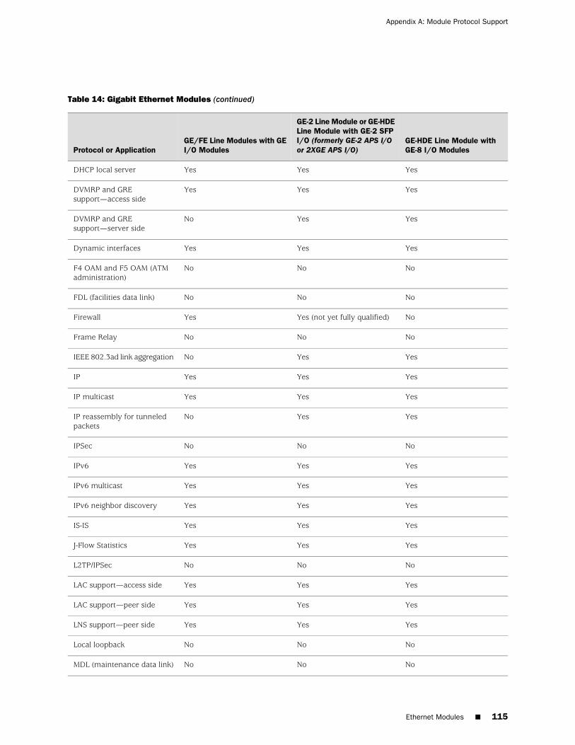
Table 14: Gigabit Ethernet Modules (continued)
GE-HDE Line Module withGE-8 I/O Modules
GE-2 Line Module or GE-HDELine Module with GE-2 SFPI/O (formerly GE-2 APS I/Oor 2XGE APS I/O)
GE/FE Line Modules with GEI/O ModulesProtocol or Application
YesYesYesDHCP local server
YesYesYesDVMRP and GREsupport—access side
YesYesNoDVMRP and GREsupport—server side
YesYesYesDynamic interfaces
NoNoNoF4 OAM and F5 OAM (ATMadministration)
NoNoNoFDL (facilities data link)
NoYes (not yet fully qualified)YesFirewall
NoNoNoFrame Relay
YesYesNoIEEE 802.3ad link aggregation
YesYesYesIP
YesYesYesIP multicast
YesYesNoIP reassembly for tunneledpackets
NoNoNoIPSec
YesYesYesIPv6
YesYesYesIPv6 multicast
YesYesYesIPv6 neighbor discovery
YesYesYesIS-IS
YesYesYesJ-Flow Statistics
NoNoNoL2TP/IPSec
YesYesYesLAC support—access side
YesYesYesLAC support—peer side
YesYesYesLNS support—peer side
NoNoNoLocal loopback
NoNoNoMDL (maintenance data link)
Ethernet Modules ■ 115
Appendix A: Module Protocol Support

Table 14: Gigabit Ethernet Modules (continued)
GE-HDE Line Module withGE-8 I/O Modules
GE-2 Line Module or GE-HDELine Module with GE-2 SFPI/O (formerly GE-2 APS I/Oor 2XGE APS I/O)
GE/FE Line Modules with GEI/O ModulesProtocol or Application
Yes (not yet fully qualified)Yes (not yet fully qualified)YesMobile IP home agent
YesYesYesMPLS
NoNoNoMultilink Frame Relay
Yes (with fragmentation andreassembly; over MPL2TP onshared tunnel-server port;dynamic only)
Yes (with fragmentation andreassembly; over MPL2TP onshared tunnel-server port;dynamic only)
NoMultilink PPP
NoYes (not yet fully qualified)YesNetwork Address Translation(NAT)
NoNoNoNBMA (multipoint ATM)
YesYesYesOSPF
YesYesYesPacket Mirroring
NoNoNoPacket over SONET
NoNoNoPPP
YesYesYesPPPoE
NoNoNoRemote loopback
YesYesYesRIP
Yes (GRE tunnels only)Yes (GRE tunnels only)YesSubscriber interfaces (static)
YesYesYesSubscriber interfaces(dynamic)
YesYesYesTransparent bridging
Yes (shared only)Yes (shared only)NoTunnel-server ports
NoYes (GE-2 line module only)YesUnified ISSU
YesYesYesVPLS (network interfaces)
YesYesYesVPLS (virtual core interfaces)
YesYesYesVRRP
116 ■ Ethernet Modules
ERX 9.3.x Module Guide

OCx/STMx GE/FE Modules
Table 15: OCx/STMx GE/FE Modules
OCx/STMx GE/FE LineModules with OC3-2 GE APSI/O Modules
(Gigabit Ethernet Interfaces)
OCx/STMx GE/FE Line Moduleswith OC3-2 GE APS I/O Modules
(OC3/STM1 ATM Interfaces)Protocol or Application
YesYesAccepts traffic destined for GRE tunnels or DVMRP(IP-in-IP) tunnels
NoNoAPS/MSP
NoYesATM
NoNoBERT
NoNoBFD
YesYesBGP
YesYesBGP/MPLS VPNs
NoYesBridged Ethernet
NoYesBridged IP
NoNoCisco HDLC
YesYesDHCP external server
YesYesDHCP local server
YesYesDVMRP and GRE support—access side
NoNoDVMRP and GRE support—server side
YesYesDynamic interfaces
NoYesF4 OAM and F5 OAM (ATM administration)
NoNoFDL (facilities data link)
YesYesFirewall
NoNoFrame Relay
NoNoIEEE 802.3ad link aggregation
YesYesIP
YesYesIP multicast
NoNoIP reassembly for tunneled packets
OCx/STMx GE/FE Modules ■ 117
Appendix A: Module Protocol Support

Table 15: OCx/STMx GE/FE Modules (continued)
OCx/STMx GE/FE LineModules with OC3-2 GE APSI/O Modules
(Gigabit Ethernet Interfaces)
OCx/STMx GE/FE Line Moduleswith OC3-2 GE APS I/O Modules
(OC3/STM1 ATM Interfaces)Protocol or Application
NoNoIPSec
YesYesIPv6
YesYesIPv6 multicast
YesYesIPv6 neighbor discovery
YesYesIS-IS
YesYesJ-Flow Statistics
NoNoL2TP/IPSec
YesYesLAC support—access side
YesYesLAC support—peer side
YesYesLNS support—peer side
NoNoLocal loopback
NoNoMDL (maintenance data link)
Yes (not yet fully qualified)NoMobile IP home agent
YesYesMPLS
NoNoMultilink Frame Relay
NoYes (with fragmentation andreassembly)
Multilink PPP
YesYesNetwork Address Translation (NAT)
NoYesNBMA (multipoint ATM)
YesYesOSPF
YesYesPacket Mirroring
NoNoPacket over SONET
NoYesPPP
YesYesPPPoE
NoNoRemote loopback
YesYesRIP
118 ■ OCx/STMx GE/FE Modules
ERX 9.3.x Module Guide

Table 15: OCx/STMx GE/FE Modules (continued)
OCx/STMx GE/FE LineModules with OC3-2 GE APSI/O Modules
(Gigabit Ethernet Interfaces)
OCx/STMx GE/FE Line Moduleswith OC3-2 GE APS I/O Modules
(OC3/STM1 ATM Interfaces)Protocol or Application
YesYes (over bridged Ethernet andIPoA)
Subscriber interfaces (static)
YesYes (over bridged Ethernet)Subscriber interfaces (dynamic)
YesYesTransparent bridging
NoNoTunnel-server ports
NoNoUnified ISSU
YesYesVPLS (network interfaces)
YesYesVPLS (virtual core interfaces)
YesNoVRRP
OCx/STMx ATM Modules
Table 16: OCx/STMx ATM Modules
OCx/STMx ATM Line Moduleswith OC12/STM4 I/O Modules
OCx/STMx ATM Line Moduleswith OC3-4 I/O ModulesProtocol or Application
YesYesAccepts traffic destined for GRE tunnels or DVMRP(IP-in-IP) tunnels
YesNoAPS/MSP
YesYesATM
NoNoBERT
NoYesBFD
YesYesBGP
YesYesBGP/MPLS VPNs
YesYesBridged Ethernet
YesYesBridged IP
NoNoCisco HDLC
YesYesDHCP external server
OCx/STMx ATM Modules ■ 119
Appendix A: Module Protocol Support

Table 16: OCx/STMx ATM Modules (continued)
OCx/STMx ATM Line Moduleswith OC12/STM4 I/O Modules
OCx/STMx ATM Line Moduleswith OC3-4 I/O ModulesProtocol or Application
YesYesDHCP local server
YesYesDVMRP and GRE support—access side
NoNoDVMRP and GRE support—server side
YesYesDynamic interfaces
YesYesF4 OAM and F5 OAM (ATM administration)
NoNoFDL (facilities data link)
YesYesFirewall
NoNoFrame Relay
NoNoIEEE 802.3ad link aggregation
YesYesIP
YesYesIP multicast
NoNoIP reassembly for tunneled packets
NoNoIPSec
YesYesIPv6
YesYesIPv6 multicast
YesYesIPv6 neighbor discovery
YesYesIS-IS
YesYesJ-Flow Statistics
NoNoL2TP/IPSec
YesYesLAC support—access side
YesYesLAC support—peer side
YesYesLNS support—peer side
YesNoLocal loopback
NoNoMDL (maintenance data link)
NoNoMobile IP home agent
YesYesMPLS
NoNoMultilink Frame Relay
120 ■ OCx/STMx ATM Modules
ERX 9.3.x Module Guide

Table 16: OCx/STMx ATM Modules (continued)
OCx/STMx ATM Line Moduleswith OC12/STM4 I/O Modules
OCx/STMx ATM Line Moduleswith OC3-4 I/O ModulesProtocol or Application
Yes (with fragmentation andreassembly)
Yes (with fragmentation andreassembly)
Multilink PPP
YesYesNetwork Address Translation (NAT)
YesYesNBMA (multipoint ATM)
YesYesOSPF
YesYesPacket Mirroring
NoNoPacket over SONET
YesYesPPP
YesYesPPPoE
NoNoRemote loopback
YesYesRIP
Yes (over bridged Ethernet andIPoA)
Yes (over bridged Ethernet andIPoA)
Subscriber interfaces (static)
Yes (over bridged Ethernet)Yes (over bridged Ethernet)Subscriber interfaces (dynamic)
YesYesTransparent bridging
NoNoTunnel-server ports
Yes (4xOC3 APS I/O notsupported)
Yes (4xOC3 APS I/O notsupported)
Unified ISSU
YesYesVPLS (network interfaces)
YesYesVPLS (virtual core interfaces)
NoNoVRRP
OCx/STMx POS and OC48 Modules
Table 17: OCx/STMx POS and OC48 Modules
OC48 Line Modulewith OC48 Frame APSI/O Module
OCx/STMx POS LineModules withOC12/STM4 I/OModules
OCx/STMx POS LineModules with OC3-4I/O ModulesProtocol or Application
YesYesYesAccepts traffic destined for GRE tunnels orDVMRP (IP-in-IP) tunnels
OCx/STMx POS and OC48 Modules ■ 121
Appendix A: Module Protocol Support

Table 17: OCx/STMx POS and OC48 Modules (continued)
OC48 Line Modulewith OC48 Frame APSI/O Module
OCx/STMx POS LineModules withOC12/STM4 I/OModules
OCx/STMx POS LineModules with OC3-4I/O ModulesProtocol or Application
NoYesNoAPS/MSP
NoNoNoATM
NoNoNoBERT
NoNoNoBFD
YesYesYesBGP
YesYesYesBGP/MPLS VPNs
NoNoNoBridged Ethernet
NoNoNoBridged IP
YesYesYesCisco HDLC
NoNoNoDHCP external server
NoNoNoDHCP local server
YesYesYesDVMRP and GRE support—access side
NoNoNoDVMRP and GRE support—access side
NoNoNoDynamic interfaces
NoNoNoF4 OAM and F5 OAM (ATM administration)
NoNoNoFDL (facilities data link)
YesYesYesFirewall
YesYesYesFrame Relay
NoNoNoIEEE 802.3ad link aggregation
YesYesYesIP
YesYesYesIP multicast
NoNoNoIP reassembly for tunneled packets
NoNoNoIPSec
Yes (PPP only)YesYesIPv6
YesYesYesIPv6 multicast
NoNoNoIPv6 neighbor discovery
122 ■ OCx/STMx POS and OC48 Modules
ERX 9.3.x Module Guide
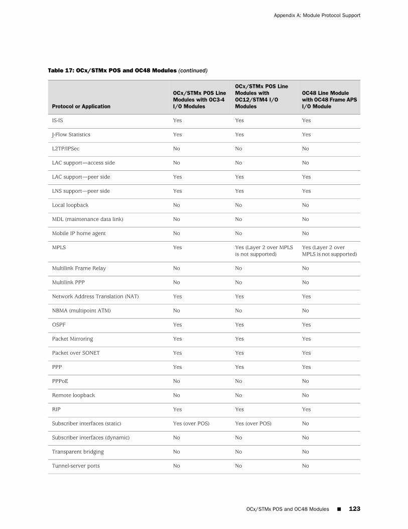
Table 17: OCx/STMx POS and OC48 Modules (continued)
OC48 Line Modulewith OC48 Frame APSI/O Module
OCx/STMx POS LineModules withOC12/STM4 I/OModules
OCx/STMx POS LineModules with OC3-4I/O ModulesProtocol or Application
YesYesYesIS-IS
YesYesYesJ-Flow Statistics
NoNoNoL2TP/IPSec
NoNoNoLAC support—access side
YesYesYesLAC support—peer side
YesYesYesLNS support—peer side
NoNoNoLocal loopback
NoNoNoMDL (maintenance data link)
NoNoNoMobile IP home agent
Yes (Layer 2 overMPLS is not supported)
Yes (Layer 2 over MPLSis not supported)
YesMPLS
NoNoNoMultilink Frame Relay
NoNoNoMultilink PPP
YesYesYesNetwork Address Translation (NAT)
NoNoNoNBMA (multipoint ATM)
YesYesYesOSPF
YesYesYesPacket Mirroring
YesYesYesPacket over SONET
YesYesYesPPP
NoNoNoPPPoE
NoNoNoRemote loopback
YesYesYesRIP
NoYes (over POS)Yes (over POS)Subscriber interfaces (static)
NoNoNoSubscriber interfaces (dynamic)
NoNoNoTransparent bridging
NoNoNoTunnel-server ports
OCx/STMx POS and OC48 Modules ■ 123
Appendix A: Module Protocol Support

Table 17: OCx/STMx POS and OC48 Modules (continued)
OC48 Line Modulewith OC48 Frame APSI/O Module
OCx/STMx POS LineModules withOC12/STM4 I/OModules
OCx/STMx POS LineModules with OC3-4I/O ModulesProtocol or Application
NoYes (4xOC3 APS I/O notsupported)
Yes (4xOC3 APS I/Onot supported)
Unified ISSU
NoNoNoVPLS (network interfaces)
YesYesYesVPLS (virtual core interfaces)
NoNoNoVRRP
Service Modules
Table 18: Service Modules
IPSec Service Line ModuleService Line Module (SM)Protocol or Application
NoNoAccepts traffic destined for GRE tunnelsor DVMRP (IP-in-IP) tunnels
NoNoAPS/MSP
NoNoATM
NoNoBERT
NoNoBFD
YesYesBGP
NoNoBGP/MPLS VPNs
NoNoBridged Ethernet
NoNoBridged IP
NoNoCisco HDLC
NoNoDHCP external server
NoNoDHCP local server
NoNoDVMRP and GRE support—access side
Yes (over dedicated tunnel server ports;DVMRP over IPsec only; GRE over IPsec)
Yes (over dedicated tunnel server ports)DVMRP and GRE support—server side
NoNoDynamic interfaces
124 ■ Service Modules
ERX 9.3.x Module Guide

Table 18: Service Modules (continued)
IPSec Service Line ModuleService Line Module (SM)Protocol or Application
NoNoF4 OAM and F5 OAM (ATMadministration)
NoNoFDL (facilities data link)
NoYesFirewall
NoNoFrame Relay
NoNoIEEE 802.3ad link aggregation
YesYesIP
NoYesIP multicast
YesYesIP reassembly for tunneled packets
YesNoIPSec
NoYesIPv6
NoYesIPv6 multicast
NoNoIPv6 neighbor discovery
YesYesIS-IS
YesYesJ-Flow Statistics
YesNoL2TP/IPSec
NoNoLAC support—access side
NoNoLAC support—peer side
NoYesLNS support—peer side
NoNoLocal loopback
NoNoMDL (maintenance data link)
NoYesMobile IP home agent
No (over GRE only)No (over GRE only)MPLS
NoNoMultilink Frame Relay
NoYes (with fragmentation and reassembly;dynamic only)
Multilink PPP
NoYesNetwork Address Translation (NAT)
NoNoNBMA (multipoint ATM)
Service Modules ■ 125
Appendix A: Module Protocol Support

Table 18: Service Modules (continued)
IPSec Service Line ModuleService Line Module (SM)Protocol or Application
YesYesOSPF
YesYesPacket Mirroring
NoNoPacket over SONET
NoYes (dynamic only)PPP
NoNoPPPoE
NoNoRemote loopback
YesYesRIP
NoYes (GRE tunnels only)Subscriber interfaces (static)
NoYes (over GRE tunnels only)Subscriber interfaces (dynamic)
NoNoTransparent bridging
Yes (dedicated only)Yes (dedicated only)Tunnel-server ports
NoYesUnified ISSU
NoNoVPLS (network interfaces)
NoNoVPLS (virtual core interfaces)
NoNoVRRP
Unchannelized E3 Modules
Table 19: Unchannelized E3 Modules
COCX-F3 Line Modules with E3-12 FRAMEI/O ModulesProtocol or Application
YesAccepts traffic destined for GRE tunnels or DVMRP (IP-in-IP) tunnels
NoAPS/MSP
NoATM (point-to-point)
NoBERT
NoBFD
YesBGP
YesBGP/MPLS VPNs
126 ■ Unchannelized E3 Modules
ERX 9.3.x Module Guide

Table 19: Unchannelized E3 Modules (continued)
COCX-F3 Line Modules with E3-12 FRAMEI/O ModulesProtocol or Application
NoBridged Ethernet
NoBridged IP
YesCisco HDLC
NoDHCP external server
NoDHCP local server
YesDVMRP and GRE support—access side
NoDVMRP and GRE support—server side
NoDynamic interfaces
NoF4 OAM and F5 OAM (ATM administration)
NoFDL (facilities data link)
YesFirewall
YesFrame Relay
NoIEEE 802.3ad link aggregation
YesIP
YesIP multicast
NoIP reassembly for tunneled packets
NoIPSec
YesIPv6
YesIPv6 multicast
NoIPv6 neighbor discovery
YesIS-IS
YesJ-Flow Statistics
NoL2TP/IPSec
NoLAC support—access side
NoLAC support—peer side
NoLNS support—peer side
NoLocal loopback
Unchannelized E3 Modules ■ 127
Appendix A: Module Protocol Support

Table 19: Unchannelized E3 Modules (continued)
COCX-F3 Line Modules with E3-12 FRAMEI/O ModulesProtocol or Application
NoMDL (maintenance data link)
NoMobile IP home agent
Yes (over PPP and Cisco HDLC; also supportsMartini encapsulation of HDLC and FrameRelay over MPLS)
MPLS
YesMultilink Frame Relay
Yes (with fragmentation and reassembly)Multilink PPP
YesNetwork Address Translation (NAT)
NoNBMA (multipoint ATM)
YesOSPF
YesPacket Mirroring
NoPacket over SONET
YesPPP
NoPPPoE
NoRemote loopback
YesRIP
NoSubscriber interfaces (static)
NoSubscriber interfaces (dynamic)
NoTransparent bridging
NoTunnel-server ports
NoUnified ISSU
NoVPLS (network interfaces)
YesVPLS (virtual core interfaces)
NoVRRP
128 ■ Unchannelized E3 Modules
ERX 9.3.x Module Guide

Unchannelized T3 Modules
Table 20: Unchannelized T3 Modules
CT3/T3-F0 Line Moduleswith CT3/T3 12 I/OModules
OCx/STMx ATM LineModules with 4xDS3 ATMI/O Modules
COCX-F3 Line Modules withCT3/T3 12 I/O ModulesProtocol or Application
YesYesYesAccepts traffic destined forGRE tunnels or DVMRP(IP-in-IP) tunnels
NoNoNoAPS/MSP
NoYesNoATM (point-to-point)
YesNoYesBERT
NoNoNoBFD
YesYesYesBGP
YesYesYesBGP/MPLS VPNs
NoYesNoBridged Ethernet
NoYesNoBridged IP
YesNoYesCisco HDLC
NoYesNoDHCP external server
NoYesNoDHCP local server
YesYesYesDVMRP and GREsupport—access side
NoNoNoDVMRP and GREsupport—access side
NoYesNoDynamic interfaces
NoYesNoF4 OAM and F5 OAM (ATMadministration)
NoNoNoFDL (facilities data link)
YesYesYesFirewall
YesNoYesFrame Relay
NoNoNoIEEE 802.3ad link aggregation
YesYesYesIP
NoNoNoIP multicast
Unchannelized T3 Modules ■ 129
Appendix A: Module Protocol Support

Table 20: Unchannelized T3 Modules (continued)
CT3/T3-F0 Line Moduleswith CT3/T3 12 I/OModules
OCx/STMx ATM LineModules with 4xDS3 ATMI/O Modules
COCX-F3 Line Modules withCT3/T3 12 I/O ModulesProtocol or Application
NoNoNoIP reassembly for tunneledpackets
NoNoNoIPSec
NoNoNoIPv6
YesYesYesIPv6 multicast
NoNoNoIPv6 neighbor discovery
YesYesYesIS-IS
YesYesYesJ-Flow Statistics
NoNoNoL2TP/IPSec
NoYesNoLAC support—access side
NoYesNoLAC support—peer side
NoYesNoLNS support—peer side
YesNoYesLocal loopback
YesNoYesMDL (maintenance data link)
NoNoNoMobile IP home agent
Yes (over PPP and CiscoHDLC; also supports Martiniencapsulation of HDLC andFrame Relay over MPLS)
YesYes (over PPP and CiscoHDLC; also supports Martiniencapsulation of HDLC andFrame Relay over MPLS)
MPLS
YesNoYesMultilink Frame Relay
YesNoYes (with fragmentation andreassembly)
Multilink PPP
YesYesYesNetwork Address Translation(NAT)
NoYesNoNBMA (multipoint ATM)
YesYesYesOSPF
YesYesYesPacket Mirroring
NoNoNoPacket over SONET
YesYesYesPPP
130 ■ Unchannelized T3 Modules
ERX 9.3.x Module Guide

Table 20: Unchannelized T3 Modules (continued)
CT3/T3-F0 Line Moduleswith CT3/T3 12 I/OModules
OCx/STMx ATM LineModules with 4xDS3 ATMI/O Modules
COCX-F3 Line Modules withCT3/T3 12 I/O ModulesProtocol or Application
NoYesNoPPPoE
YesNoYesRemote loopback
YesYesYesRIP
YesYes (over bridged Ethernetand IPoA)
YesSubscriber interfaces (static)
YesYes (over bridged Ethernet)YesSubscriber interfaces(dynamic)
NoYesNoTransparent bridging
NoNoNoTunnel-server ports
NoYesNoUnified ISSU
NoYesNoVPLS (network interfaces)
YesYesYesVPLS (virtual core interfaces)
NoNoNoVRRP
Unchannelized T3 Modules ■ 131
Appendix A: Module Protocol Support

132 ■ Unchannelized T3 Modules
ERX 9.3.x Module Guide

Appendix B
Module LEDs
This appendix describes the LEDs found on ERX modules. Module LEDs can showyou the current status of a module and alert you to a problem with the module orone of its ports. We recommend that you familiarize yourself with LED activity sothat you can easily detect and correct a module-related problem with minimal or nosystem downtime. This appendix contains the following sections:
■ LED Identification on page 133
■ Redundancy Status on page 137
LED Identification
The system's modules have two sets of status LEDs. The top set indicates overallrouter and module status. The bottom set indicates module-specific status, such asport status (line modules) or fan status (SRP module).
The number next to the port status LED on a line module corresponds to the numberof the port on the I/O module. Some line modules have more port status LEDs thanthe number of ports on the I/O module. In these cases, only the LEDs for thecorresponding ports on the I/O modules are active.
For example, an OCx/STMx line module can pair with either an OC3-4 or anOC12/STM4 I/O module. Consequently, the line module has four port status LEDsfor OC3/STM1 operation. However, only the top set of port status LEDs IS activeduring OC12/STM4 operation.
Table 21 on page 133 lists the functions of the module and port status LEDs.
Table 21: LED Identification and Activity Descriptions
ON to OFFOFF to ONLED ColorLED IndicatorLED LabelLEDLocation
Failure detectedSelf-test passedGreenModule statusOKAllmodules
Diagnostic test runningFailure detectedRedModule statusFAIL
Module offineModule onlineGreenModule statusONLINE
LED Identification ■ 133
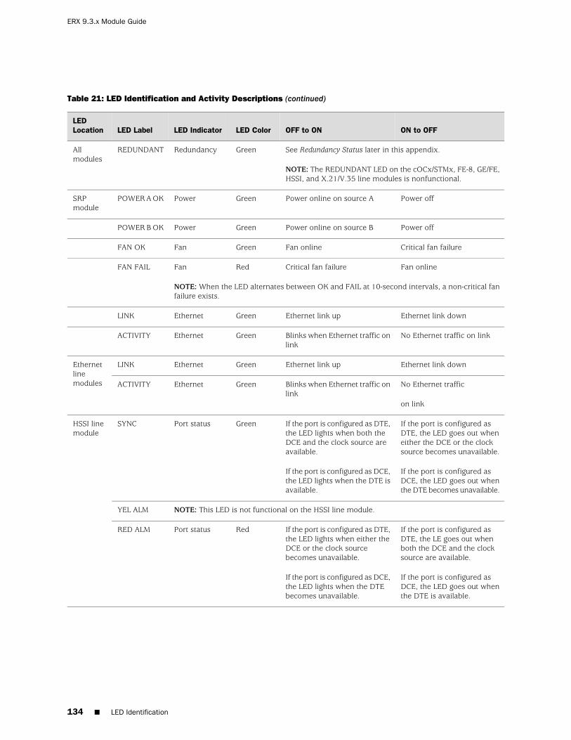
Table 21: LED Identification and Activity Descriptions (continued)
ON to OFFOFF to ONLED ColorLED IndicatorLED LabelLEDLocation
See Redundancy Status later in this appendix.
NOTE: The REDUNDANT LED on the cOCx/STMx, FE-8, GE/FE,HSSI, and X.21/V.35 line modules is nonfunctional.
GreenRedundancyREDUNDANTAllmodules
Power offPower online on source AGreenPowerPOWER A OKSRPmodule
Power offPower online on source BGreenPowerPOWER B OK
Critical fan failureFan onlineGreenFanFAN OK
Fan onlineCritical fan failureRedFanFAN FAIL
NOTE: When the LED alternates between OK and FAIL at 10-second intervals, a non-critical fanfailure exists.
Ethernet link downEthernet link upGreenEthernetLINK
No Ethernet traffic on linkBlinks when Ethernet traffic onlink
GreenEthernetACTIVITY
Ethernet link downEthernet link upGreenEthernetLINKEthernetlinemodules No Ethernet traffic
on link
Blinks when Ethernet traffic onlink
GreenEthernetACTIVITY
If the port is configured asDTE, the LED goes out wheneither the DCE or the clocksource becomes unavailable.
If the port is configured asDCE, the LED goes out whenthe DTE becomes unavailable.
If the port is configured as DTE,the LED lights when both theDCE and the clock source areavailable.
If the port is configured as DCE,the LED lights when the DTE isavailable.
GreenPort statusSYNCHSSI linemodule
NOTE: This LED is not functional on the HSSI line module.YEL ALM
If the port is configured asDTE, the LE goes out whenboth the DCE and the clocksource are available.
If the port is configured asDCE, the LED goes out whenthe DTE is available.
If the port is configured as DTE,the LED lights when either theDCE or the clock sourcebecomes unavailable.
If the port is configured as DCE,the LED lights when the DTEbecomes unavailable.
RedPort statusRED ALM
134 ■ LED Identification
ERX 9.3.x Module Guide
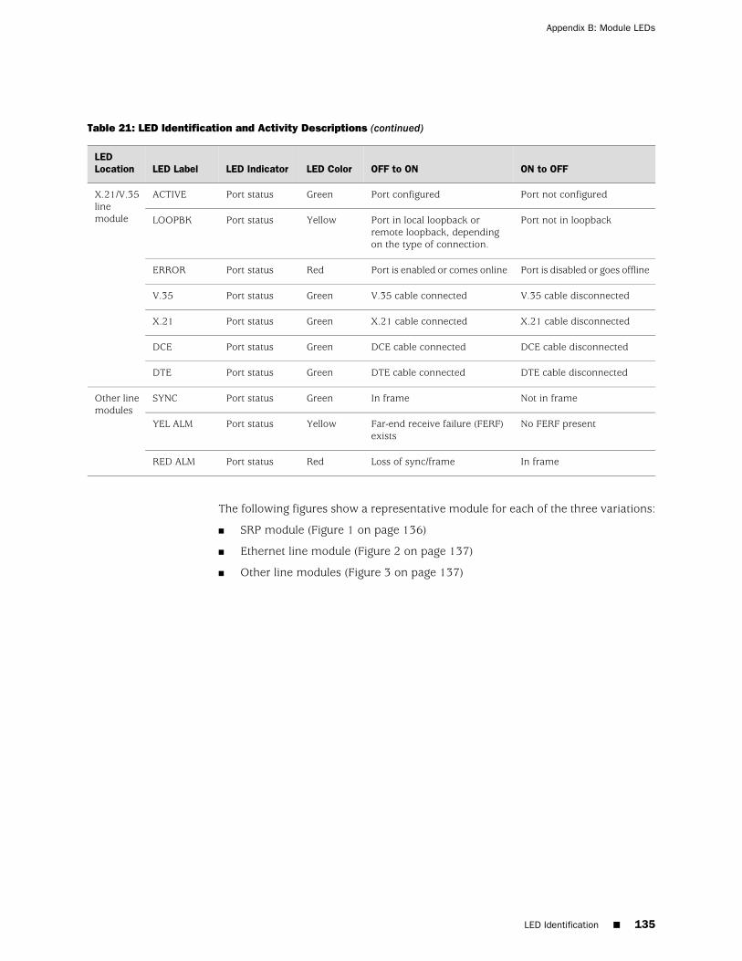
Table 21: LED Identification and Activity Descriptions (continued)
ON to OFFOFF to ONLED ColorLED IndicatorLED LabelLEDLocation
Port not configuredPort configuredGreenPort statusACTIVEX.21/V.35linemodule Port not in loopbackPort in local loopback or
remote loopback, dependingon the type of connection.
YellowPort statusLOOPBK
Port is disabled or goes offlinePort is enabled or comes onlineRedPort statusERROR
V.35 cable disconnectedV.35 cable connectedGreenPort statusV.35
X.21 cable disconnectedX.21 cable connectedGreenPort statusX.21
DCE cable disconnectedDCE cable connectedGreenPort statusDCE
DTE cable disconnectedDTE cable connectedGreenPort statusDTE
Not in frameIn frameGreenPort statusSYNCOther linemodules
No FERF presentFar-end receive failure (FERF)exists
YellowPort statusYEL ALM
In frameLoss of sync/frameRedPort statusRED ALM
The following figures show a representative module for each of the three variations:
■ SRP module (Figure 1 on page 136)
■ Ethernet line module (Figure 2 on page 137)
■ Other line modules (Figure 3 on page 137)
LED Identification ■ 135
Appendix B: Module LEDs
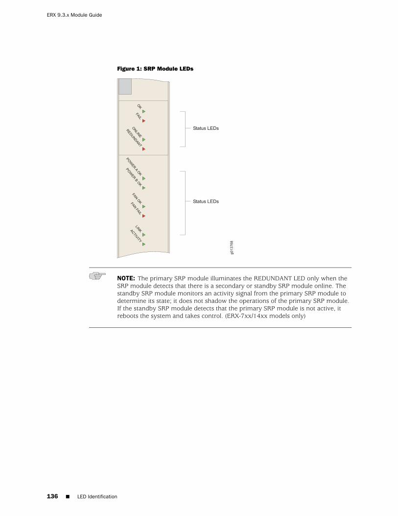
Figure 1: SRP Module LEDs
NOTE: The primary SRP module illuminates the REDUNDANT LED only when theSRP module detects that there is a secondary or standby SRP module online. Thestandby SRP module monitors an activity signal from the primary SRP module todetermine its state; it does not shadow the operations of the primary SRP module.If the standby SRP module detects that the primary SRP module is not active, itreboots the system and takes control. (ERX-7xx/14xx models only)
136 ■ LED Identification
ERX 9.3.x Module Guide

Figure 2: FE2 Module LEDs
Figure 3: E3 and T3 Module LEDs
Redundancy Status
You can determine the redundancy state of line modules by examining the onlineand redundant status LEDs (ERX-7xx/14xx models only). See Table 22 on page 138.
Redundancy Status ■ 137
Appendix B: Module LEDs

NOTE: The REDUNDANT LED on the cOCx/STMx, FE-8, GE/FE, and HSSI modulesis nonfunctional.
Table 22: Redundancy Status of a Line Module
State of the Line ModuleREDUNDANT LEDONLINE LED
Module is booting or is an inactive primary line module.OffOff
Module is active, but no standby module is available.OffOn
Module is in standby state.OnOff
Module is active, and a standby module is available.OnOn
138 ■ Redundancy Status
ERX 9.3.x Module Guide

Appendix C
Product Reclamation and RecyclingProgram
■ Product Reclamation and Recycling Program on page 139
Product Reclamation and Recycling Program
Juniper Networks is committed to environmentally responsible behavior. As part ofthis commitment, we continually work to comply with environmental standards suchas the European Union’s Waste Electrical and Electronic Equipment (WEEE) Directiveand Restriction of Hazardous Substances (RoHS) Directive.
These directives and other similar regulations from countries outside the EuropeanUnion regulate electronic waste management and the reduction or elimination ofspecific hazardous materials in electronic products. The WEEE Directive requireselectrical and electronics manufacturers to provide mechanisms for the recyclingand reuse of their products. The RoHS Directive restricts the use of certain substancesthat are commonly found in electronic products today. Restricted substances includeheavy metals, including lead, and polybrominated materials. The RoHS Directive,with some exemptions, applies to all electrical and electronic equipment.
In accordance with Article 11(2) of Directive 2002/96/EC (WEEE), products put onthe market after 13 August 2005 are marked with the following symbol or includeit in their documentation: a crossed-out wheeled waste bin with a bar beneath.
Juniper Networks provides recycling support for our equipment worldwide to complywith the WEEE Directive. For recycling information, go tohttp://www.juniper.net/environmental, and indicate the type of Juniper Networks equipmentthat you wish to dispose of and the country where it is currently located, or contactyour Juniper Networks account representative.
Product Reclamation and Recycling Program ■ 139

Products returned through our reclamation process are recycled, recovered, ordisposed of in a responsible manner. Our packaging is designed to be recycled andshould be handled in accordance with your local recycling policies.
140 ■ Product Reclamation and Recycling Program
ERX 9.3.x Module Guide


Juniper Networks, the Juniper Networks logo, JUNOS, NetScreen, ScreenOS, and Steel-Belted Radius are registered trademarks of Juniper Networks, Inc. inthe United States and other countries. JUNOSe is a trademark of Juniper Networks, Inc. All other trademarks, service marks, registered trademarks, orregistered service marks are the property of their respective owners.
Juniper Networks assumes no responsibility for any inaccuracies in this document. Juniper Networks reserves the right to change, modify, transfer, orotherwise revise this publication without notice.
Products made or sold by Juniper Networks or components thereof might be covered by one or more of the following patents that are owned by or licensedto Juniper Networks: U.S. Patent Nos. 5,473,599, 5,905,725, 5,909,440, 6,192,051, 6,333,650, 6,359,479, 6,406,312, 6,429,706, 6,459,579, 6,493,347,6,538,518, 6,538,899, 6,552,918, 6,567,902, 6,578,186, and 6,590,785.
E-series™ Routing Platforms ERX™ Module Guide, Release 9.3.xCopyright © 2008, Juniper Networks, Inc.All rights reserved. Printed in USA.
Writing: John Borelli, Sarah Lesway-Ball, Fran SingerEditing: Ben MannIllustration: John Borelli
Revision History17 October 2008—Revision 1
The information in this document is current as of the date listed in the revision history.