Embed Size (px)
Citation preview

ENVIROPROTECTOR FRP STORMWATER
TREATMENT SYSTEM
INSTALLATION MANUAL
PROTECTOR
1 Ropes Crossing Boulevard,
Ropes Crossing 2760
NSW, Australia

ENVIROPROTECTOR by PROTECTOR
PROTECTOR – ENVIROPROTECTOR Stormwater treatment system Installation Manual 2
CONTENTS 1. Introduction .................................................................................................................................... 4
2. Scope of Product ............................................................................................................................. 7
2.1. Applications ............................................................................................................................. 7
3. ENVIROPROTECTOR Stormwater treatment system Specifications ............................................... 8
3.1. Design and Construction Standards ........................................................................................ 8
3.2. Design Methodology ............................................................................................................... 8
3.3. Materials of construction ........................................................................................................ 8
3.3.1. Corrosion ......................................................................................................................... 8
3.3.2. Reinforcement ................................................................................................................ 8
3.3.3. Tank ................................................................................................................................. 8
4. Safety .............................................................................................................................................. 9
4.1. Warning ................................................................................................................................... 9
4.2. Caution .................................................................................................................................... 9
4.3. Important Information ............................................................................................................ 9
4.4. General Information ............................................................................................................... 9
4.5. Before you Begin ..................................................................................................................... 9
5. Prior To Installation ......................................................................................................................... 9
5.1. Design Considerations........................................................................................................... 10
5.2. Location ................................................................................................................................. 10
6. Procedure for Installation ............................................................................................................. 10
6.1. General .................................................................................................................................. 10
6.2. Pre-Installation Checks .......................................................................................................... 10
6.3. Handling and Preparation ..................................................................................................... 11
6.4. Site Preparation .................................................................................................................... 14
6.5. Anti-Floatation Ballasts for FRP ENVIROPROTECTOR Tanks ................................................. 14
6.6. Bed and Backfill ..................................................................................................................... 16
6.7. ENVIROPROTECTOR Installation with a Fibreglass Underground Tank ................................ 17
6.8. Piping Penetrations/Fittings ................................................................................................. 18
6.9. Invert ..................................................................................................................................... 19
6.10. Top Pad ............................................................................................................................. 19
6.11. Wet Hole Installation ........................................................................................................ 20

ENVIROPROTECTOR by PROTECTOR
PROTECTOR – ENVIROPROTECTOR Stormwater treatment system Installation Manual 3
7. Traffic and Non-Traffic Load Covers ............................................................................................. 22
7.1. Fibreglass Flat Tops Without Traffic Loads ........................................................................... 22
7.2. Fibreglass Flat Tops with Traffic Load ................................................................................... 22
8. After Installation ........................................................................................................................... 23
8.1. Live Surface Loads ................................................................................................................. 23
9. Typical Installation Drawing .......................................................................................................... 24
10. Maintenance ............................................................................................................................. 25
10.1. ENVIROPROTECTOR Chamber Maintenance .................................................................... 25
10.2. Interior Maintenance ........................................................................................................ 25
11. Warranty and Expected Lifespan .............................................................................................. 26
12. FIBREGLASS ENVIROPROTECTOR INSTALLATION NOTES .......................................................... 27

ENVIROPROTECTOR by PROTECTOR
PROTECTOR – ENVIROPROTECTOR Stormwater treatment system Installation Manual 4
1. INTRODUCTION Protector is a company excelling in the design, manufacture and production of
fibreglass tanks to be utilised in stormwater treatment technologies. The newest
development designed by Protector is the ENVIROPROTECTOR, a filtration device to be
implemented into stormwater systems to remove large sediments, gross pollutants,
hydrocarbons and oil from stormwater runoff. Once treated this water is then returned
into the water system, efficiently keeping our water clean.
The Protector EnviroProtector is a specialist stormwater filter for heavily polluted traffic
areas, designed for installation within new or existing chambers, The Fiberglass housing is
safe and easy to fit on site. The EnviroProtector operates in an up-flow process resulting in
minimal head drop between the inlet and the outlet. The stormwater is treated within the
unit by the following processes: sedimentation, filtration, adsorption and precipitation. It is
suitable for Heavy Metal, TSS and Nutrient reduction. At the Heart of the EnviroProtector is
the Enviro Filter, a mix of technologies including Oil Coalescing, Glass 30Micron Filtration
and zeolite adsorption materials to provide the maximum contaminant removal. Combined
with the up-flow water movement, reducing headloss and improving even flow makes the
ENVIRPROTECTOR the most formidable tertiary filter on the market.
PROTECTOR products, manufactured by the Australian-based manufacturer, PROTECTOR,
provide high quality solutions for fast and efficient installation, needed for today’s fast track
building methods. Built to the highest specifications, the ENVIROPROTECTOR product is
designed and built to BS4994-1987 and ASME RPT1. Popular with councils, municipal, water
authorities, civil and construction customers and incorporating state-of-the-art technology,

ENVIROPROTECTOR by PROTECTOR
PROTECTOR – ENVIROPROTECTOR Stormwater treatment system Installation Manual 5
our stormwater treatment solutions provide simple solutions to some of the most complex
problems in the water and waste water industry.
ENVIROPROTECTOR products are designed to reduce operating costs and optimise operating
efficiency. Above and below ground options can be used in a multitude of applications, in
both domestic and commercial environments, from small, single pump units to dual pump
systems, with capacities of up to 250,000 litres per unit. The entire range is easy to install,
easy to handle, light and robust.
PROTECTOR’s dynamic enterprise has roots in the industry that go back to over 40 years of
engineering, design experience and product knowledge passed from generation to
generation to where it is today. PROTECTOR products, known as the leading edge of
composite manufacture here in Australia are renowned for their quality with painstaking
attention to detail that has become the product and basis for the company’s operation
formed by years of experience and knowledge in the fibreglass and water industry.
Today PROTECTOR plant, based in Sydney, comprises of modern ‘state of the art’ filament
winding and computerised robots to ensure fast operations and precision from concept to
completion. The basis for the company’s operation, with continuous success, both yours and
ours!
Fibreglass Reinforced Polymer are composite materials made of a polymer matrix reinforced
with fibres and are high strength, long life materials that are commonly used in aerospace,
automotive and water industries. Our FRP products are coated with a final internal and
external layer of C’veil and CSM to provide a higher resistance to corrosion which makes
them ideal to be implemented in tank applications such as our stormwater treatment
systems. They can be exposed to the water for years without being corrupted. Light weight,

ENVIROPROTECTOR by PROTECTOR
PROTECTOR – ENVIROPROTECTOR Stormwater treatment system Installation Manual 6
resistant to high temperature, strong in compression with our guarantee of easy on-site
installation are some of the desirable features that FRP indicates. Furthermore, FRP plates
have higher mechanical strength which enables them to carry higher loads compared to
plastics. PROTECTOR has designed and manufactured stormwater treatment system utilizing
FRP to provide a quality product. ENVIROPROTECTOR stormwater treatment system have a
better durability, and highly resistant to any impact and corrosion whilst providing the best
stormwater treatment available.
This document provides an in-depth and detailed collation of the technical information on
the ENVIROPROTECTOR product including its installation practices, suitable usage,
advantages and limitations. Information is also provided on the filtration system, its design
and its maintenance.

ENVIROPROTECTOR by PROTECTOR
PROTECTOR – ENVIROPROTECTOR Stormwater treatment system Installation Manual 7
2. SCOPE OF PRODUCT This system is design as an underground stormwater treatment system, mainly in the uses of
Sedimentation, filtration and adsorption of nutrients, chemicals, hydrocarbons and oils. This
tertiary treatment system is capable of being installed in a wide range of flow conditions, do
to the fully equipped high flow bypass feature. It is easily retrofitted into pre-existing
stormwater systems and is the perfect tertiary treatment system to be implemented at the
final stages of a treatment train to ensure complete contaminant removal. It is a highly
efficient and effective system that removes a high percentage of contaminants and due to
its wide range of configurations, filter arrangements and size variations the system is
suitable for almost all site demands.
At the Heart of the EnviroProtector is the Enviro Filter, a mix of technologies including Oil
Coalescing, Glass 30Micron Filtration and zeolite adsorption materials to provide the
maximum contaminant removal. Combined with the up-flow water movement, reducing
headloss and improving even flow makes the ENVIRPROTECTOR the most formidable tertiary
filter on the market. A single ENVIROPROTECTOR system can come equipped with a wide
number of filters as per the design requirement of the site, from a single filter to up to 23
filters.
2.1. Applications The ENVIROPROTECTOR is suitable for many applications. Its high filtration rate and large
array of configurations and sizes allows for this system to be suitable in almost all situations.
Its ability to also be combined with other filtration systems, such as the ECOPROTECTOR, as
a combined system ensure that this system can be used in a wide range of applications. The
most common applications are listed below:
Car Parks & Shopping Centres
Council Depots
Industrial Estates
Heavy Vehicle Maintenance
Transport Depots & Loading Bays
Tunnels
Highways & Transport Corridors
Recycling Yards
Airport Aprons & Tarmacs

ENVIROPROTECTOR by PROTECTOR
PROTECTOR – ENVIROPROTECTOR Stormwater treatment system Installation Manual 8
3. ENVIROPROTECTOR STORMWATER TREATMENT
SYSTEM SPECIFICATIONS
3.1. Design and Construction Standards AS1546 - Underground tank design
AS1170 - Loading code
3.2. Design Methodology The underground tank Design Methodology is based on the use of the above standards as described,
where applicable:
AS1546 is used to formulae the design load of soil/groundwater and use for the testing
methods applied.
AS1170 is used to formulae the design loads from active loads that the stations are subject
to, including the required roof slab design. This standard is also used to formulae the ballast
requirements for ant floatation.
3.3. Materials of construction
3.3.1. Corrosion
Internal
o Internal Corrosion Barrier, moulded with a resin rich C’veil and CSM layers
o Resin rich Corrosion barrier constructed from Hetron 922 Vinyl Ester Resin
o C’veil will be Regina 80gsm Surface Tissue
o The Internal Corrosion Barrier is manufactured in accordance with AS2634
External
o External layer will a resin rich CSM layer and C-Glass veil finished with ISO/NPG Flow coat
layer for external finish to required colour
3.3.2. Reinforcement
Manufactured using Chop / Hoop Construction, on a computer-controlled Filament Winding
machine.
Shell Thickness are in accordance to the design requirements set out in the methodology. o
Structural layers are constructed from Polyplex Isophthalic Resin with CSM & Hoop in
accordance with Ratio’s as specified by the design.
Fiberglass ‘E’ glass is used for both chopped and continuous strands.
3.3.3. Tank
The Stormwater treatment system Battered base is circumferentially benched to WSA04—
2005
FRP Flanged fittings are made in accordance with AS2634, and flanges are installed as per
AS2634. Both the internal and external FRP attachment laminates are in accordance with
AS2634

ENVIROPROTECTOR by PROTECTOR
PROTECTOR – ENVIROPROTECTOR Stormwater treatment system Installation Manual 9
4. SAFETY These instructions should not be interpreted in any way to put one's health at risk, or to harm
property and/or the environment. The following definitions will serve as a guide when reading this
manual:
4.1. Warning Indicates a potentially hazardous situation, which if not avoided could result in death or serious
injury.
4.2. Caution Indicates a potentially hazardous situation, which if not avoided may result in minor or moderate
injury. A caution without the safety alert symbol indicates a potentially hazardous situation, which if
not avoided may result in property damage.
4.3. Important Information Proper installation of each ENVIROPROTECTOR is essential:
• To ensure the safety of all the individuals involved in the installation.
• To prevent ENVIROPROTECTOR damage and/or failure, which could lead to product loss and
environmental contamination.
• To validate the ENVIROPROTECTOR warranty.
4.4. General Information WARNING ENVIROPROTECTORs are a confined space per OHS guidelines. Follow proper
confined space safety procedures.
PROTECTOR fibreglass ENVIROPROTECTORs are designed for installation with concrete top
pad and bottom slabs. The following instructions reflect the approved methods for installing
ENVIROPROTECTORs. Follow all OHS, Federal, State or Local, safety and environmental codes
and regulations
4.5. Before you Begin • Read, understand and follow these instructions.
• Barricade the work area.
• Review and prepare to complete the installation checklist as the installation progresses. If you
have questions on other ENVIROPROTECTOR installation details, call Technical Support at 02 8006
4229
5. PRIOR TO INSTALLATION Our Products are Suitable for almost all locations, from an industrial Car Park to Residential
Catchment areas, from mining areas to Airports, our large range of products will provide the
solution you need. Our FRP designs will strive to keep our streams, waterways and our
environment clean.
ENVIROPROTECTOR by PROTECTOR
PROTECTOR – ENVIROPROTECTOR Stormwater treatment system Installation Manual 10
5.1. Design Considerations Important considerations must be taken when deciding on which Protector product is
suitable for your needs. With the assistance of our team of experienced staff we can offer
endless assistance and advice in this matter. The most important aspects we consider
helping solve your needs are:
Physical Locale and rainfall conditions
Catchment Size
Contaminant types
Flow Rate
Risk Analysis
All our products ensure clean, treated water to flow back into the environment.
5.2. Location Location is vital for design considerations for PROTECTOR to provide the best possible
ENVIROPROTECTOR FRP tank for you site demands. Information shall need to be supplied to
our team depicting all information necessary for us to select the perfect ENVIROPROTECTOR
tank for you. Rainfall data, flow rates, storm conditions and other aspects of the surrounding
area are recommended to be provided or detailed.
For optimal installation and transport of the ENVIROPROTECTOR FRP tanks, clear and safe
access to the stormwater treatment system, stormwater treatment system installation site
and control panels must be considered to facilitate ease of installation, maintenance and
servicing. The access manways built into our ENVIROPROTECTOR tanks must be accessible at
all times and well-sealed to prevent foreign contaminants from entering the stormwater
treatment system. Access roads must be available for delivery of the tanks, with no intrusion
or obstacles that may cause damage to the FRP tank upon delivery and installation.
6. PROCEDURE FOR INSTALLATION
6.1. General The construction method used in the manufacture of FRP ENVIROPROTECTOR stormwater
treatment system utilises high strength Composite Laminar of Resin and Glass
These materials are extremely strong as well as corrosion resistant. But, like all engineered
products, care must be taken during installation to ensure that long, trouble free operation
can be expected.
6.2. Pre-Installation Checks 1. After unloading inspect the tank skin for any damage during transportation and crane slinging.
Should any minor surface damage be evident, this must be reported to your supplier and inspected before proceeding with the installation.
2. Check walls, floor and roof for any surface damage. If minor repairs are required, report as outlined in above.
3. Check all pipe penetrations through wall, ensure that no damage has occurred and that the surfaces are clean for later joining to incoming and outgoing pipes and vents.

ENVIROPROTECTOR by PROTECTOR
PROTECTOR – ENVIROPROTECTOR Stormwater treatment system Installation Manual 11
4. Check hold down bolts on pedestals and tighten if necessary.
6.3. Handling and Preparation WARNING Do not stand on or under ENVIROPROTECTOR while it is being lifted. This could
result in personal injury or death.
• Do not drop or impact the ENVIROPROTECTOR.
• ENVIROPROTECTORs should be stored horizontally and chocked, using only appropriate materials
such as sandbags, tires, or other soft or pliable materials.
• Upon ENVIROPROTECTOR delivery and when lifting ENVIROPROTECTOR, visually inspect entire
exterior surface of the ENVIROPROTECTOR for shipping or handling damage.
• If the ENVIROPROTECTOR must be moved by rolling, ensure that ground to be traversed is smooth
and free of rocks, debris, or other hard objects.
• Do not roll or set the ENVIROPROTECTOR on any pipe stub out, accessory or appurtenance
installed on the ENVIROPROTECTOR.
• The contractor is responsible for rigging, unloading and securing the ENVIROPROTECTOR.
• When lifting the ENVIROPROTECTOR in the horizontal position, use two slings with a spreader bar.
• Use a minimum of two lift lugs when pivoting the ENVIROPROTECTOR from horizontal to vertical.
• Utilize all lift lugs provided at the ENVIROPROTECTOR top for vertical lifting.
• Only a pliable strap or rope should contact the ENVIROPROTECTOR, do not use chains, steel cables
or hard metallic slings.
Lifting and Tank Handling from Truck
Once the truck arrives:
1. check condition of tank to ensure no damage has incurred in Transport. All issues must be
photographed and sent to PROTECTOR for verification.
Lifting procedure:
1. Place Soft Slings around the body of the station

ENVIROPROTECTOR by PROTECTOR
PROTECTOR – ENVIROPROTECTOR Stormwater treatment system Installation Manual 12
2. Slings to be ¼ from each end
3. Connect two leg chains to slings
4. Lift and Place on Ground
5. Place tank on ground as the same Position of the truck
6. Ensure that the tank is resting on supports. Ensure that the flanges do not come in to
contact with the ground.

ENVIROPROTECTOR by PROTECTOR
PROTECTOR – ENVIROPROTECTOR Stormwater treatment system Installation Manual 13
7. Ensure that the base of the tank is on soft ground (I.E. grass)
8. Place a Short Soft Sling through each Lifting Lug Eyes Provided
9. With a toe Chain set or (1 redundant) ensure that the ties are the same length.
10. Try to make the chains if possible to reduce angle
11. Take up tension on the 2 Lugs beside the Valve Pit.

ENVIROPROTECTOR by PROTECTOR
PROTECTOR – ENVIROPROTECTOR Stormwater treatment system Installation Manual 14
Below: Image to show 50% of the way to Vertical, showing that only 2 chains will be tight at this
point.
12. Once the tank is vertical with all chains tight, the tank is ready to be moved to the
excavation for installation.
6.4. Site Preparation Dimensions of the excavation should be wide enough to provide sufficient working room
around the ENVIROPROTECTOR. Minimum anti floatation ring and ballast dimensions are
specified in (Table 1, page 7)
Anti-floatation ring and ballast designs in (Table 1, page 7) meet Australian Standard Code S3600A.
(Dead load resisting floatation have a factor of safety of 0.9 applied.)
6.5. Anti-Floatation Ballasts for FRP ENVIROPROTECTOR Tanks The tank walls are designed to resist the crushing effects of underground pressures to the
full depth of the wall without the need to be surrounded by concrete. However, in
conditions of high water table, external ballast will be required to resist upward buoyancy
forces. It is important to note that, as ENVIROPROTECTOR tanks do not require outer
concrete walls for strength, the ballast concrete may be placed in the most economical
position, which is at the base of the excavation normally to the base locking ring. Concrete
must be poured in accordance with ‘best practice’ as set out by the industry Standard.
Please refer to the Concrete Manufacturers’ Association Handbook. The calculation of the
volume of concrete ballast is not covered in this document. This calculation should be
carried out by a certified civil engineer.

ENVIROPROTECTOR by PROTECTOR
PROTECTOR – ENVIROPROTECTOR Stormwater treatment system Installation Manual 15
WARNING Collapsing excavation walls can cause injury or death. Do not enter the
ENVIROPROTECTOR excavation unless necessary and in compliance with OHS regulations.
Follow OHS guidelines for excavations.
ENVIROPROTECTORS • Lower ENVIROPROTECTOR onto Compacted Base then place Wet
concrete around the Unit, until it covers the lock-in Rib plus meets the Ballast Quantity in
(Table 1 and figure 1, page 7.)
Cold concrete joints are not allowed. Fibreglass solid bottom ENVIROPROTECTORs with
external reinforcing ribs must be installed in a continuous and monolithic concrete pour.
Concrete must extend 100mm above the lock-in rib from the ENVIROPROTECTOR bottom,
and around the entire circumference of the ENVIROPROTECTOR. (Refer to figure 1, page 7) •
Concrete slab must fill all gaps and voids in and around the external tank lock-in ribs. • It
may be necessary to add ballast (water) inside the ENVIROPROTECTOR to counteract
buoyancy until the concrete is cured.
ANTI FLOATATION RING CONCRETE SLAB Use minimum 20 MPa concrete for anti-floatation
and ballast Final concrete depth, size, thickness and reinforcements shall meet the minimum
requirements in these instructions and applicable tables. Anti-floatation ring should extend a
minimum of (refer to table 1, page 7) in all directions from the ENVIROPROTECTOR outer
diameter.
CAUTION Voids in the concrete slab around external structural anchors will result in product
damage and environmental contamination.
Below are the details for the Ballast installation for the ENVIROPROTECTOR range.
Model Ballast Thickness (mm)
Balast Depth (mm)
Total Depth (mm) Ballast Length

ENVIROPROTECTOR by PROTECTOR
PROTECTOR – ENVIROPROTECTOR Stormwater treatment system Installation Manual 16
EPS.1000 300 1200 300
EPS.1200 300 1500 305
EPS.1500 350 1500 520
EPS.1850 400 1500 645
EPS.2200 450 1800 730
EPS.2500 550 1800 785
EPS.3000 650 1800 900
6.6. Bed and Backfill Proper backfill selection and compaction are required for a proper installation. The allowed
backfills are shown in Table D-1 along with the degree of compaction required.
Bed and Backfill Compaction
Soil type-pipe bedding material (Unified Soil Classification System See Table D-2)
Minimum Degree of Compaction Required*
Fine - grained soils (Liquid Limit < 50) with medium to no plasticity with less than 25% coarse grained particles. CL, ML, ML - CL,
High
Fine grained soils (Liquid Limit < 50) with medium to no plasticity with more than 25% coarse grained particles. CL, ML, ML - CL
Moderate
Coarse grained soils containing more than 12% fines. GM, GC, SM, SC
Moderate
Coarse grained soils with less than 12% fines. GW, GP, SW, SP
Slight
Coarse grained soils with less than 12% fines. GW, GP, SW, SP
Dumped
* Degree of compaction:
• Dumped - No compaction effort.
• Slight - Some compactive effort. In-place density <85% standard compaction. Or < 40%
modified compaction.
• Moderate - Intermediate level of compactive effort, In-place density >/=85% and < 95%
standard compaction, or >/=40% and <70% modified compaction.
• High - Considerable compactive effort. In-place density >/= 95% standard compaction, or >/=
70% modified compaction
• The difference in the “dumped” and “slight” degree of compaction values is significant and
are based on the method of construction, not the measured densities. “Dumped” means
that there is absolutely no compaction of the embedment soil. “Slight” means there was
something done that increased the soil density, even if minor, such as water settling, jetting,
flooding, equipment travel, and in some cases, foot traffic.
• For stable soils (cohesion ≥ 36 kpa and / or a bearing capacity ≥ 170 kpa a minimum 300mm
of backfill must be placed around the ENVIROPROTECTOR.
• For unstable soils (cohesion ≤ 36kpa and ultimate bearing capacity ≤ 170 kpa). -
ENVIROPROTECTORs 1200mm diameter or smaller require a minimum 600mm of backfill
around the entire circumference of the ENVIROPROTECTOR. - ENVIROPROTECTORs

ENVIROPROTECTOR by PROTECTOR
PROTECTOR – ENVIROPROTECTOR Stormwater treatment system Installation Manual 17
larger than 1200mm diameter require a minimum backfill of ½ the ENVIROPROTECTOR
diameter around the entire circumference of the ENVIROPROTECTOR.
• If muck, bog or peat are present, consult with a Geotechnical Engineer for backfill and
excavation requirements.
• For permafrost conditions, consult with a Geotechnical Engineer for backfill and excavation
requirements. Keep backfill dry and free of ice in freezing conditions. Ensure that no foreign
objects such as large stones, concrete clumps, tree roots/limbs, or debris is in the backfill
surrounding the ENVIROPROTECTOR.
Prevent large surges of backfill from displacing the ENVIROPROTECTOR.
Table D-2
Letter and Definition
Second Letter and Definition
G = Gravel P = Poorly Graded (uniform particle sizes)
S = Sand W = Well Graded (diversified particle sizes)
M = Silt H = High Plasticity
C = Clay L = Low Plasticity
O = Organic
6.7. ENVIROPROTECTOR Installation with a Fibreglass Underground Tank CAUTION Not using approved backfill material may result in tank failure and environmental
contamination.
If the ENVIROPROTECTOR is installed in the same excavation as an underground fibreglass
tank, the backfill around the ENVIROPROTECTOR must also meet the tank backfill
requirements to not compromise the tank installation. Tank backfill requirements are more

ENVIROPROTECTOR by PROTECTOR
PROTECTOR – ENVIROPROTECTOR Stormwater treatment system Installation Manual 18
restricted and strict conformance to the tank backfill requirements in MAN 600 must be met
for both the ENVIROPROTECTOR and tank.
6.8. Piping Penetrations/Fittings CAUTION Always wear safety glasses and protective clothing when cutting on the
ENVIROPROTECTOR, failure to do so can result in personal injury.
• Pipe penetration cut-outs should be round holes and should be no larger than the pipe diameter
plus 25mm. - Make cuts using a saw with a masonry or diamond grit blade. - Do not use an axe or
other impact type tools.
• Accessories must be installed and used in strict accordance with the manufacturer’s instructions.
• All piping must have a flexible connector installed directly on the fitting or accessory to allow for a
minimum 15mm differential settlement between the ENVIROPROTECTOR and the pipe. If more
than 15mm differential settlement is expected, choose a flexible connector designed for the
expected settlement. Do not backfill around the ENVIROPROTECTOR until the concrete slab has
hardened. Add backfill in maximum 900mm lifts evenly around the ENVIROPROTECTOR to avoid
uneven backfill loads.
• A flexible joint on each connecting pipe is required to relieve stresses from differential backfill
movement or soil consolidation. Backfill should be added to the invert elevation of each connecting
pipe, the connection made and sealed, before continuing to backfill.
WARNING To prevent fire or explosion hazard, PROTECTOR recommends air driven tools
whenever possible. DO NOT use power tools where flammable vapours or liquids exist. Also,
when electric hand tools are used, be aware of potential shock hazards. Wear protective
clothing and eye protection. ENVIROPROTECTORs may be a confined space. Follow proper
safety procedures.

ENVIROPROTECTOR by PROTECTOR
PROTECTOR – ENVIROPROTECTOR Stormwater treatment system Installation Manual 19
6.9. Invert Invert specified by Certified Engineer. The invert may be at any angle and may project up the
ENVIROPROTECTOR any distance.
6.10. Top Pad The ENVIROPROTECTOR is designed to support the dead weight of an 200mm thick square
pad 600mm larger than the diameter of the ENVIROPROTECTOR (centred on the
ENVIROPROTECTOR) along with a dynamic T-44 traffic load as long as the pad is designed to
distribute the loads on the ENVIROPROTECTOR perimeter and not on the interior of the lid.
If the static load will exceed the 200mm pad weight or the traffic load will exceed T-44, the
pad must be 1200mm larger than the ENVIROPROTECTOR diameter (centred on the
ENVIROPROTECTOR) and all of the pad and / or traffic loads must be supported by the soil
around the ENVIROPROTECTOR and not by the ENVIROPROTECTOR itself.
Fibreglass flat tops 1000mm through 2500mm diameter are designed to support 200mm
concrete pads without internal supports while the concrete cures.
The concrete pad must be designed to be self-supporting after cured.
The pad shall be specified by the Certified Engineer.
FIBREGLASS FLAT TOPS WITHOUT TRAFFIC LOAD
• The pad must be larger than the ENVIROPROTECTOR a minimum of 300mm in all directions.
• Maximum 200mm concrete pad thickness.
FIBREGLASS FLAT TOPS WITH TRAFFIC LOAD
• The pad must be larger than the ENVIROPROTECTOR a minimum of 600mm in all directions.

ENVIROPROTECTOR by PROTECTOR
PROTECTOR – ENVIROPROTECTOR Stormwater treatment system Installation Manual 20
• The Certified Engineer shall specify the pad strength and reinforcement so that the static
weight of an 200mm thick square pad (no more than 600mm larger than the diameter of the
ENVIROPROTECTOR centred on the ENVIROPROTECTOR) along with a dynamic T-44 traffic
load must be distributed on the ENVIROPROTECTOR perimeter and not on the interior of the
lid.
• If either the static pad load or the dynamic traffic load is exceeded, all of the pad and / or
traffic loads must be supported by the soil around the ENVIROPROTECTOR and not by the
ENVIROPROTECTOR itself.
6.11. Wet Hole Installation CAUTION: Never allow an empty tank to remain in a wet hole, or a dry hole that may
become wet unless anchoring and backfilling have been completed. Failure to anchor and
backfill may damage the tank or surrounding property.
Firstly, make site preparation as per section B.
Pump the water from the hole to maintain minimum water level. Add a minimum of 300mm
of well-placed backfill material (Must Be Crushed Gravel) to the hole, and level the bed to
assure uniform bottom support for the tank. Position the tank in the hole.
Partially ballast tank using water until it settles firmly on the prepared bed. Ballast level in a
tank must never exceed water level in hole during installation. Use only enough ballast to
sink the tank. One tank is level and ballasted, carefully place concrete ballast as per section
C. then processed to sections D, E (if applicable), F, G and H.
Fibreglass ENVIROPROTECTORs With External Anti Floatation Rib:
The ENVIROPROTECTOR bottom is designed to BS4994 to any resist buckling of the
ENVIROPROTECTOR bottom from external water pressure and internal pressure, in the
installed condition with a compacted base to Figure C.1, and the perimeter of the
ENVIROPROTECTOR including the anti-floatation lock-in Rib embedded in concrete. This
table must be followed for the concrete slab design for all ENVIROPROTECTORs with
fiberglass external ribs. These slabs are designed to AS3600. In some cases, the slab and/or
reinforcing design is controlled by temperature requirements cases by flexure. Use
minimum 20Mpa concrete. Since some of the slab designs are controlled by temperature,
the slab thickness should not be without the approval of a Design Engineer
ENVIROPROTECTOR by PROTECTOR
PROTECTOR – ENVIROPROTECTOR Stormwater treatment system Installation Manual 21
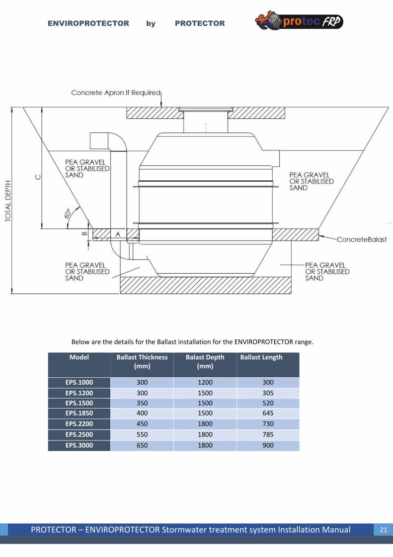
Below are the details for the Ballast installation for the ENVIROPROTECTOR range.
Model Ballast Thickness (mm)
Balast Depth (mm)
Ballast Length
EPS.1000 300 1200 300
EPS.1200 300 1500 305
EPS.1500 350 1500 520
EPS.1850 400 1500 645
EPS.2200 450 1800 730
EPS.2500 550 1800 785
EPS.3000 650 1800 900

ENVIROPROTECTOR by PROTECTOR
PROTECTOR – ENVIROPROTECTOR Stormwater treatment system Installation Manual 22
7. TRAFFIC AND NON-TRAFFIC LOAD COVERS
7.1. Fibreglass Flat Tops Without Traffic Loads The pad must be larger than the ENVIROPROTECTOR a minimum of 300mm in all directions.
Maximum 200mm concrete pad thickness.
7.2. Fibreglass Flat Tops with Traffic Load • The pad must be larger than the ENVIROPROTECTOR a minimum of 600mm in all directions.
• The Certified Engineer shall specify the pad strength and reinforcement so that the static
weight of an 200mm thick square pad (no more than 600mm larger than the diameter of the
ENVIROPROTECTOR centred on the ENVIROPROTECTOR) along with a dynamic T-44 traffic
load must be distributed on the ENVIROPROTECTOR perimeter and not on the interior of the
lid.
• If either the static pad load or the dynamic traffic load is exceeded, all of the pad and / or
traffic loads must be supported by the soil around the ENVIROPROTECTOR and not by the
ENVIROPROTECTOR itself.

ENVIROPROTECTOR by PROTECTOR
PROTECTOR – ENVIROPROTECTOR Stormwater treatment system Installation Manual 23
8. AFTER INSTALLATION After the installation procedure has been followed and the ENVIROPROTECTOR system is
secured in place, a few final steps must be adhered to, to maximise the lifespan of the FRP
Underground tank.
It must be ensured that the tank will have no contact from outside environmental conditions
and protection from contact with moving factors. These include motor vehicles, farm
equipment, construction and any animal interference. If not installed completely
underground, fencing must be included on site to ensure no contact by environmental
conditions from high wind, and existing fauna interactions. The lids must be designed to be
able to take the impact of any contact from motor vehicles or animals, and alternatively
must not cause damage to any vehicles or and animals that walk or drive upon the lid. Hence
the surroundings must be carefully cordoned off and the lid designed for the sites demands.
8.1. Live Surface Loads Light duty Fibreglass or aluminium access covers are not suitable for vehicular traffic. If a
package stormwater treatment system is to be positioned in a location subject to vehicular
traffic, then a certified cast iron cover must be used. Either Class B or Class D covers may be
selected to suit the appropriate wheel loading. Special design consideration must be given to
the surface slab, which must provide a frill re-enforced bridge support to transmit slab loads
to virgin ground. In this case, the services of a qualified civil engineer should be engaged to
provide adequate slab designs.

ENVIROPROTECTOR by PROTECTOR
PROTECTOR – ENVIROPROTECTOR Stormwater treatment system Installation Manual 24
9. TYPICAL INSTALLATION DRAWING

ENVIROPROTECTOR by PROTECTOR
PROTECTOR – ENVIROPROTECTOR Stormwater treatment system Installation Manual 25
10. MAINTENANCE A necessary requirement of the use of the EnviroProtector is the need for regular inspection,
maintenance and cleaning. This regularity is defined by the catchment area that it is in and
the features and properties of the surroundings. Regardless of the catchment area features,
it is recommended by PROTECTOR that there is a mandatory inspection after 1 month of use
after installation to determine the amount of capture of gross pollutants and sediments and
determination of regularity of maintenance can be taken from this.
As previously stated, any form of weather conditions outside the norm of which the specific
ENVIROPROTECTOR is design fall, be it high rainfall or heavy storm conditions, an immediate
inspection is recommended.
NB: when maintenance is conducted on the ENVIROPROTECTOR system, ensure that all
Workplace health and Safety precautions and directions are adhered to and the Confined
Space Regulations are carefully followed when required.
The cleaning and maintenance procedure is simple, requiring removal of the access cover
and inserting a suction hose into the chamber, recommended use of a vacuum loader truck.
Remove all forms of refuse and debris before entering the chamber. Always ensure cleaning
is begun from the inlet side of the chamber and ensure carefully resecuring of the access
cover when completed.
Specific maintenance procedures of each aspect of the stormwater treatment system is
outlined below. All maintenance must be carried out by some authorised personnel and all
OH and S regulations and confined space regulations must be strictly followed.
10.1. ENVIROPROTECTOR Chamber Maintenance 1. Remove access manway carefully and safely.
2. Using a Crane or lifting apparatus, carefully remove each filter from its position in the filter
floor
3. Using a vacuum or hose truck, insert a suction hose into the chamber. Remove all forms of
refuse, silt and debris before entering the chamber. Always ensure cleaning is begun from
the inlet side of the chamber and ensure carefully resecuring of the access cover when
completed.
4. Replace each ENVIROFILTER system with the new filter
5. Restart operation
10.2. Interior Maintenance 1. Silt and sediment Chamber - Remove all sediment, gross pollutants and anything other trash
that can restrict water flow.
2. Central Bypass Riser – ensure that all clogging is removed, and that water can flow without
obstacle through the bypass
3. Clean all inlet dropper, outlet pipe and vent of any possible blockages or debris
4. Ensure no structure damage has occurred on the filter floor

ENVIROPROTECTOR by PROTECTOR
PROTECTOR – ENVIROPROTECTOR Stormwater treatment system Installation Manual 26
11. WARRANTY AND EXPECTED LIFESPAN The quality assurance of our FRP products ensures that the ENVIROPROTECTOR range of FRP
underground packaged tanks has an expected lifespan of 50 years. There is also a guarantee
of our ENVIROPROTECTOR products to be free of defects in material and workmanship for
one (1) year from the date of shipment form our manufacturing factory. The obligation of
this warranty, statutory or otherwise, is limited to replacement or repair at factory or at a
point designated by PROTECTOR, of such part as shall appear to us, upon inspection at such
point, to have been defective in material or workmanship. This warranty does not obligate
PROTECTOR to bear the cost of labour or transportation charges in connection with
replacement or repair of defective part; nor shall it apply to a pump upon which repairs, or
alterations have been made unless authorised by PROTECTOR in writing. No Warranty is
made in respect to electrical control panels, pumps, motors or trade accessories, such being
subject to warranties of their respective manufacturers. No express, limited or statutory
warranty, other than herein set forth is made or authorised to be made by PROTECTOR. in
no event shall PROTECTOR be liable for consequential damages or contingent liabilities
arising out of failure of any Packaged Stormwater treatment system or parts thereof to
operate properly. Packaged Stormwater treatment system must be installed by licensed
tradesmen. Failure to do so voids all Warranty.

ENVIROPROTECTOR by PROTECTOR
PROTECTOR – ENVIROPROTECTOR Stormwater treatment system Installation Manual 27
12. FIBREGLASS ENVIROPROTECTOR
INSTALLATION NOTES ..................................................................................................................................................................
..................................................................................................................................................................
..................................................................................................................................................................
..................................................................................................................................................................
..................................................................................................................................................................
..................................................................................................................................................................
..................................................................................................................................................................
..................................................................................................................................................................
..................................................................................................................................................................
..................................................................................................................................................................
..................................................................................................................................................................
..................................................................................................................................................................
..................................................................................................................................................................
..................................................................................................................................................................
..................................................................................................................................................................
..................................................................................................................................................................
..................................................................................................................................................................
..................................................................................................................................................................
..................................................................................................................................................................
..................................................................................................................................................................
..................................................................................................................................................................
..................................................................................................................................................................
..................................................................................................................................................................
..................................................................................................................................................................
..................................................................................................................................................................
..................................................................................................................................................................
..................................................................................................................................................................
..................................................................................................................................................................
..................................................................................................................................................................
..................................................................................................................................................................
..................................................................................................................................................................
..................................................................................................................................................................
..................................................................................................................................................................
..................................................................................................................................................................
..................................................................................................................................................................
..................................................................................................................................................................
..................................................................................................................................................................
..................................................................................................................................................................
..................................................................................................................................................................
..................................................................................................................................................................
..................................................................................................................................................................
..................................................................................................................................................................

ENVIROPROTECTOR by PROTECTOR
PROTECTOR – ENVIROPROTECTOR Stormwater treatment system Installation Manual 28
..................................................................................................................................................................
..................................................................................................................................................................
..................................................................................................................................................................
..................................................................................................................................................................
..................................................................................................................................................................
..................................................................................................................................................................
..................................................................................................................................................................
..................................................................................................................................................................
..................................................................................................................................................................
..................................................................................................................................................................
..................................................................................................................................................................
..................................................................................................................................................................
..................................................................................................................................................................
..................................................................................................................................................................
..................................................................................................................................................................
..................................................................................................................................................................
..................................................................................................................................................................
..................................................................................................................................................................
..................................................................................................................................................................
..................................................................................................................................................................
..................................................................................................................................................................
..................................................................................................................................................................
..................................................................................................................................................................
..................................................................................................................................................................
..................................................................................................................................................................
..................................................................................................................................................................
..................................................................................................................................................................
..................................................................................................................................................................
..................................................................................................................................................................
..................................................................................................................................................................
..................................................................................................................................................................
..................................................................................................................................................................