Embed Size (px)
Citation preview

7-1Auckland Regional Council Technical Publication # 10
Chapter 7Filtration design,construction and maintenance7.1 Introduction
Filtration includes a diverse group of practices for treating stormwater runoff. The common factor is thateach uses some kind of filtering media such as sand, soil, gravel, peat, or compost to filter out contaminants.They are especially suited for small catchment areas, are primarily water quality practices and they generallyhave little water quantity control benefit.
Although diverse, stormwater filters have several common design components.
> inflow regulation> pretreatment> filter media> outflow mechanism
This chapter discusses sand filtration and rain gardens.
Sand filters can be either surface or underground, and their designs are similar. Sand filters work by sedimen-tation and filtration, generally with an inflow point to a sedimentation chamber and an underdrain in a subse-quent filtration chamber that discharges filtered stormwater.
The ARC is investigating the use of alternative filter media over the next year for enhanced contaminantreduction, especially of soluble contaminants.
Rain gardens are generally surface depressions with key elements including a grass filter, a sand/loam soilmixture, shallow ponding, plantings of trees and shrubs, and an underdrain.
7.2 Water quality performance
Filtration practices have:
> an excellent ability to remove suspended solids> a variable ability to reduce phosphorus> low nitrogen removal in sand filtration systems but a moderate ability in rain gardens> higher ability to remove bacteria, metals and hydrocarbons than other practices such as ponds
Filters reduce contaminants by a variety of chemical, physical, and biological processes. The dominant proc-ess will vary from site to site and between contaminants. In some cases the contaminants are transformed(decomposition, decay) and in other cases they simply accumulate in the filer media. The removal processesinclude:
> sedimentation> adsorption> volatilisation> filtration> biological processes
7-2Auckland Regional Council Technical Publication # 10
SedimentationSedimentation is one ofthe principal mecha-nisms for the removal ofmany contaminantsfrom the water column.Sedimentation is impor-tant for the removal ofsuspended solids,particulate nitrogen, hy-drocarbons and heavymetals.
AdsorptionAdsorption of contami-nants onto the surfaceof suspended solids isthe dominant mecha-nism for dissolved con-taminants. Adsorptionoccurs through threemain processes:
> electrostatic attraction,> physical attraction and> chemical reaction.
Adsorption is important for removing ammonium ions, phosphorus, viruses and heavy metals.
Precipitation, dissolution, and complexation
Many metals dissolve or precipitate in response to changes in water chemistry. Metals form insolublesulphides under reducing conditions and insoluble oxides and hydroxides under oxidising conditions.
Volatilisation
Contaminants may enter the atmosphere by evaporation and aerosol formation under windy conditions.Common contaminants removed by volatilisation include oil, chlorinated hydrocarbons and mercury.
FiltrationThis occurs as particulates are mechanically filtered through a filter media, vegetation and biota. Densevegetation and low velocities promote greater removal efficiencies. Organic matter, phosphorus, bacteria,and sediments are effectively removed by infiltration through the soil.
Biological processes
Vegetation offers high contaminant absorption and biological uptake potential as well as providing anenvironment for significant microbial activity.
Rain gardens utilise additional processes that can further improve water quality function. Mulch has beenfound to be very effective in removing heavy metals through organic complexing with the hydroxyl andcarboxyl sites on the organic molecules. Soil bacteria can metabolise (use as a carbon energy source) oil,grease, and petrol into CO
2 and water in the presence of adequate nutrients and oxygen. Plants are known to
uptake, transpire, accumulate and detoxify heavy metals and many other toxic compounds.
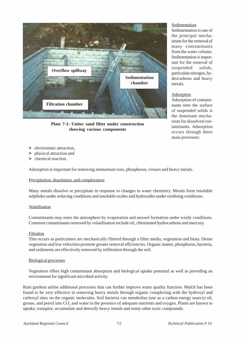
Plate 7-1: Unitec sand filter under constructionshowing various components
Overflow spillway
Sedimentationchamber
Filtration chamber
7-3Auckland Regional Council Technical Publication # 10
In summary, the overall contaminant removal of stormwater filter systems is on a par with that for otherpractices with higher removal for some contaminants, and lower removal for others. Table 7-1 providesexpected removal efficiencies for sand filters. Also included in the table is a comparison of removal expec-tations and results from monitoring efforts at the Unitec sand filter.
Table 7-1Contaminant removal expectations (%)
Contaminant Removal expectations Unitec siteSediment >75 92Total lead >75 98Total zinc >75 93Total copper >75 90Hydrocarbons >75 not done
While the results of the Unitec monitoring are extremely good, the monitoring period was of short duration(two months) and the largest storm monitored was 7.7 mm of total rainfall. The results therefore should beconsidered indicative as opposed to absolute. Overseas data does support the range of results that have beenobtained in the ARC study and show sand filters to be effective at contaminant removal.
In addition to the water quality performance, peak discharge rates were reduced significantly between inflowand outflow. For all storms, the mean reduction in peak flow was 64%. The greater the inflow peak, thegreater the reduction in peak discharge. For the top 25 percentile of peak inlet flows (i.e. > 11.5 l/s), the flowreduction averaged 90%. These results were for small storm events. It is expected that discharges beyondthe filters design specification (water quality storm) would have diminishing benefits.
7.3 Design approach
7.3.1 Objectives
1. To reduce coarse sediments, metals, nutrients, PAH, bacteria and gross contaminants from stormwaterrunoff from low and high levels of imperviousness for residential, commercial, and industrial site.
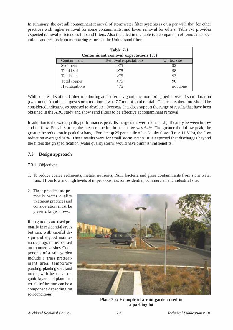
2. These practices are pri-marily water qualitytreatment practices andconsideration must begiven to larger flows.
Rain gardens are used pri-marily in residential areasbut can, with careful de-sign and a good mainte-nance programme, be usedon commercial sites. Com-ponents of a rain gardeninclude a grass pretreat-ment area, temporaryponding, planting soil, sandmixing with the soil, an or-ganic layer, and plant ma-terial. Infiltration can be acomponent depending onsoil conditions.
Plate 7-2: Example of a rain garden used ina parking lot
7-4Auckland Regional Council Technical Publication # 10
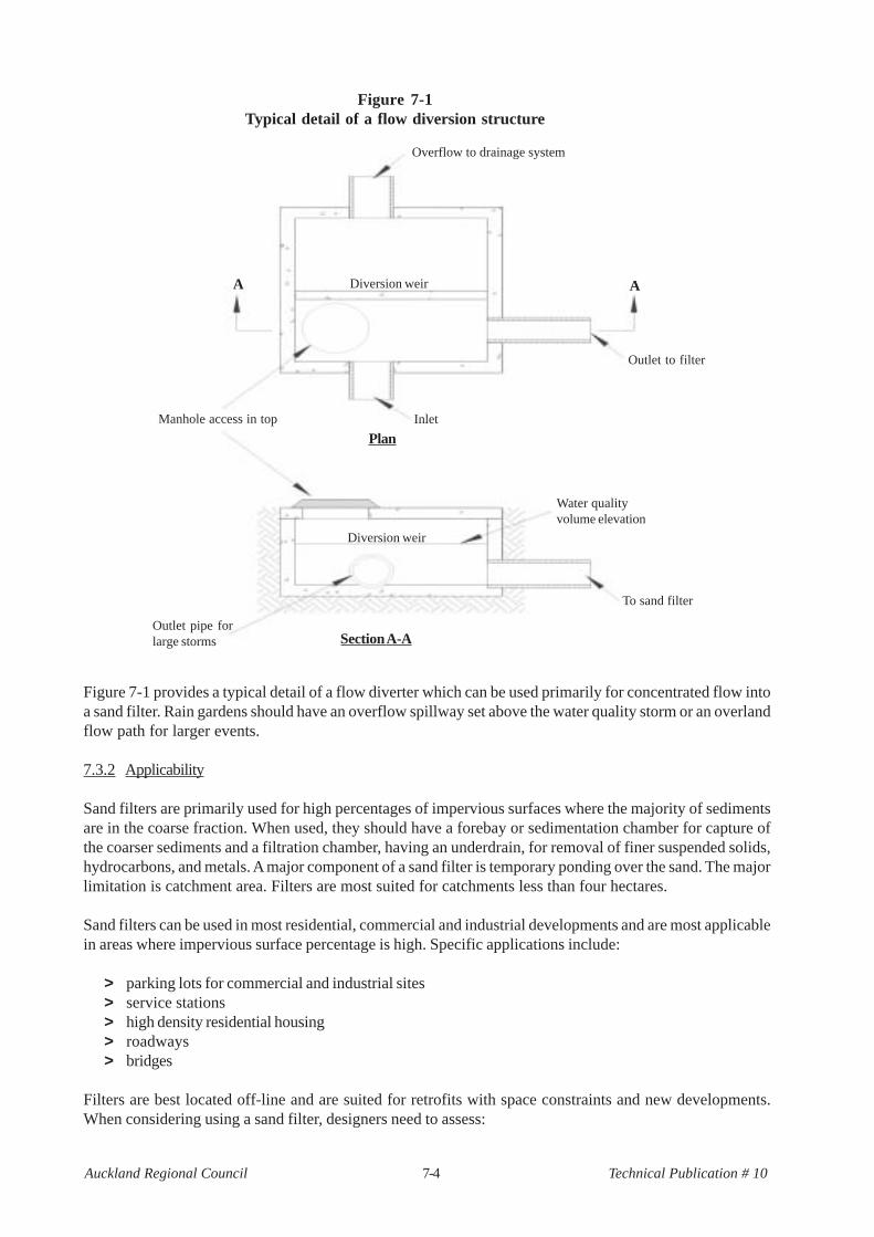
Figure 7-1 provides a typical detail of a flow diverter which can be used primarily for concentrated flow intoa sand filter. Rain gardens should have an overflow spillway set above the water quality storm or an overlandflow path for larger events.
7.3.2 Applicability
Sand filters are primarily used for high percentages of impervious surfaces where the majority of sedimentsare in the coarse fraction. When used, they should have a forebay or sedimentation chamber for capture ofthe coarser sediments and a filtration chamber, having an underdrain, for removal of finer suspended solids,hydrocarbons, and metals. A major component of a sand filter is temporary ponding over the sand. The majorlimitation is catchment area. Filters are most suited for catchments less than four hectares.
Sand filters can be used in most residential, commercial and industrial developments and are most applicablein areas where impervious surface percentage is high. Specific applications include:
> parking lots for commercial and industrial sites> service stations> high density residential housing> roadways> bridges
Filters are best located off-line and are suited for retrofits with space constraints and new developments.When considering using a sand filter, designers need to assess:
Figure 7-1Typical detail of a flow diversion structure
Overflow to drainage system
Diversion weir
Diversion weir
Outlet to filter
InletManhole access in top
A A
Water qualityvolume elevation
To sand filter
Outlet pipe forlarge storms
Plan
Section A-A
7-5Auckland Regional Council Technical Publication # 10
> the loading rate> filter loading capacity> the minimum maintenance frequency
Most street and road particulate matter is in coarser fractions, roughly in sand and gravel equivalent sizes.However, most stormwater contaminants are associated with fine particles. As sand filters have two cham-bers, the sedimentation chamber is more effective at removing the sand and gravel component. The finer siltsand clays are more effectively captured by the filtration component.
As mentioned in the Objectives section, rain gardens are ideally suited for residential developments but canbe used on other land uses if pre-treatment is provided to reduce potential clogging. They are ideally suitedfor small catchments of less than one hectare. They are generally on-line practices with an overflow pro-vided for larger storms.
7.4 Design procedure
The design approach for sand filters and rain gardens is somewhat different and will be discussed individu-ally. Both rely on treating the runoff from the water quality storm and the use of filter media for treatment.However the rain garden approach is a bit more complicated as the flow must travel through an organic/sandmedia, not just sand.
7.4.1 Sand filter design procedure
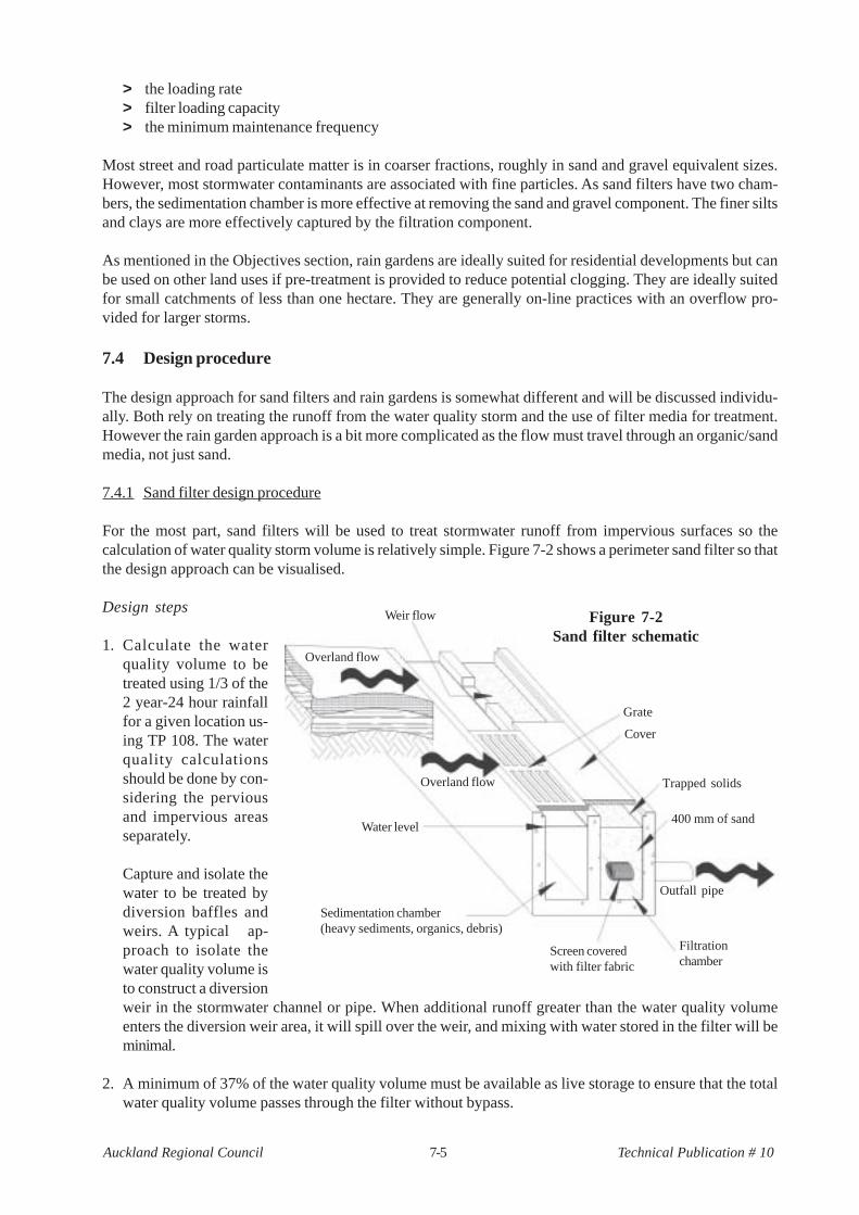
For the most part, sand filters will be used to treat stormwater runoff from impervious surfaces so thecalculation of water quality storm volume is relatively simple. Figure 7-2 shows a perimeter sand filter so thatthe design approach can be visualised.
Design steps
1. Calculate the waterquality volume to betreated using 1/3 of the2 year-24 hour rainfallfor a given location us-ing TP 108. The waterquality calculationsshould be done by con-sidering the perviousand impervious areasseparately.
Capture and isolate thewater to be treated bydiversion baffles andweirs. A typical ap-proach to isolate thewater quality volume isto construct a diversionweir in the stormwater channel or pipe. When additional runoff greater than the water quality volumeenters the diversion weir area, it will spill over the weir, and mixing with water stored in the filter will beminimal.
2. A minimum of 37% of the water quality volume must be available as live storage to ensure that the totalwater quality volume passes through the filter without bypass.
Figure 7-2Sand filter schematic
Weir flow
Overland flow
Overland flow
Grate
Cover
Trapped solids
400 mm of sand
Outfall pipe
Filtrationchamber
Screen coveredwith filter fabric
Water level
Sedimentation chamber(heavy sediments, organics, debris)
7-6Auckland Regional Council Technical Publication # 10
3. The sand filtration chamber should be sized by the following equation:
IaHd
f
Af =
k(h+df)t
f
where
Af
= surface area of sand bed in (m2)I
a= impervious drainage area contributing runoff (m2)
H = runoff depth to be treated (m)d
f= sand bed depth (m)
k = coefficient of permeability for sand filter in metres per dayh = average depth of water (WQ storm) above surface of sand in metres (1/2 max. depth)tf
= time required for runoff to pass through the filter media in days
The following values should be used:
IaH = the water quality volume in cubic metres
tf
= 2 days (maximum)k = 1 metre per dayd
f= 0.4 metres (minimum)
Key filtration chamber design specifications:
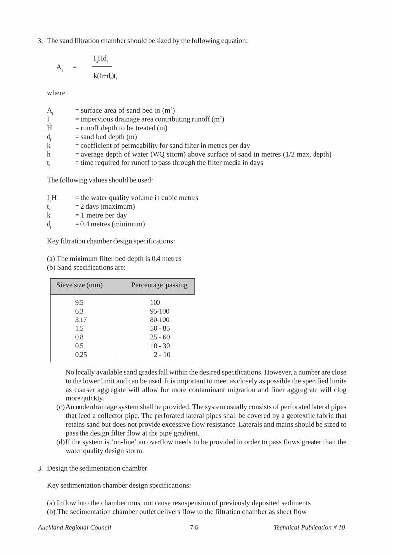
(a) The minimum filter bed depth is 0.4 metres(b) Sand specifications are:
Sieve size (mm) Percentage passing
9.5 1006.3 95-1003.17 80-1001.5 50 - 850.8 25 - 600.5 10 - 300.25 2 - 10
No locally available sand grades fall within the desired specifications. However, a number are closeto the lower limit and can be used. It is important to meet as closely as possible the specified limitsas coarser aggregate will allow for more contaminant migration and finer aggregrate will clogmore quickly.
(c)An underdrainage system shall be provided. The system usually consists of perforated lateral pipesthat feed a collector pipe. The perforated lateral pipes shall be covered by a geotextile fabric thatretains sand but does not provide excessive flow resistance. Laterals and mains should be sized topass the design filter flow at the pipe gradient.
(d)If the system is ‘on-line’ an overflow needs to be provided in order to pass flows greater than thewater quality design storm.
3. Design the sedimentation chamber
Key sedimentation chamber design specifications:
(a) Inflow into the chamber must not cause resuspension of previously deposited sediments(b) The sedimentation chamber outlet delivers flow to the filtration chamber as sheet flow
7-7Auckland Regional Council Technical Publication # 10
(c) The sedimentation chamber must be at least 25% of the filtration area detailed in step 2(d) Flow velocities in the sedimentation area are required to be below 0.25 m/s(e) The sedimentation chamber must have a permanent pool with a minimum depth of 0.4 metres to
reduce resuspension of trapped sediments(f) The sedimentation chamber should be configured to avoid short-circuiting of the flow. This requires a
long narrow pool or tank, the use of baffles to lengthen the flow path or baffles to provide flowresistance at the inlet.
7.4.2 Rain garden design
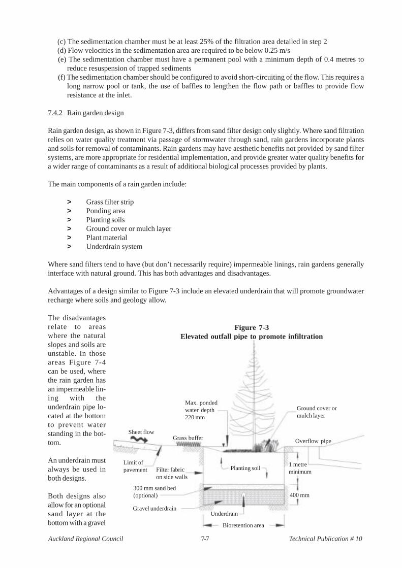
Rain garden design, as shown in Figure 7-3, differs from sand filter design only slightly. Where sand filtrationrelies on water quality treatment via passage of stormwater through sand, rain gardens incorporate plantsand soils for removal of contaminants. Rain gardens may have aesthetic benefits not provided by sand filtersystems, are more appropriate for residential implementation, and provide greater water quality benefits fora wider range of contaminants as a result of additional biological processes provided by plants.
The main components of a rain garden include:
> Grass filter strip> Ponding area> Planting soils> Ground cover or mulch layer> Plant material> Underdrain system
Where sand filters tend to have (but don’t necessarily require) impermeable linings, rain gardens generallyinterface with natural ground. This has both advantages and disadvantages.
Advantages of a design similar to Figure 7-3 include an elevated underdrain that will promote groundwaterrecharge where soils and geology allow.
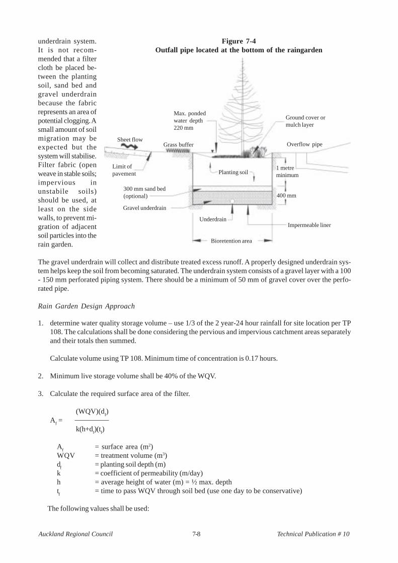
The disadvantagesrelate to areaswhere the naturalslopes and soils areunstable. In thoseareas Figure 7-4can be used, wherethe rain garden hasan impermeable lin-ing with theunderdrain pipe lo-cated at the bottomto prevent waterstanding in the bot-tom.
An underdrain mustalways be used inboth designs.
Both designs alsoallow for an optionalsand layer at thebottom with a gravel
Figure 7-3Elevated outfall pipe to promote infiltration
Max. pondedwater depth220 mm
Sheet flowGrass buffer
Limit ofpavement Filter fabric
on side walls
300 mm sand bed(optional)
Gravel underdrain
Planting soil
Underdrain
Bioretention area
400 mm
1 metreminimum
Overflow pipe
Ground cover ormulch layer
7-8Auckland Regional Council Technical Publication # 10
underdrain system.It is not recom-mended that a filtercloth be placed be-tween the plantingsoil, sand bed andgravel underdrainbecause the fabricrepresents an area ofpotential clogging. Asmall amount of soilmigration may beexpected but thesystem will stabilise.Filter fabric (openweave in stable soils;impervious inunstabile soils)should be used, atleast on the sidewalls, to prevent mi-gration of adjacentsoil particles into therain garden.
The gravel underdrain will collect and distribute treated excess runoff. A properly designed underdrain sys-tem helps keep the soil from becoming saturated. The underdrain system consists of a gravel layer with a 100- 150 mm perforated piping system. There should be a minimum of 50 mm of gravel cover over the perfo-rated pipe.
Rain Garden Design Approach
1. determine water quality storage volume – use 1/3 of the 2 year-24 hour rainfall for site location per TP108. The calculations shall be done considering the pervious and impervious catchment areas separatelyand their totals then summed.
Calculate volume using TP 108. Minimum time of concentration is 0.17 hours.
2. Minimum live storage volume shall be 40% of the WQV.
3. Calculate the required surface area of the filter.
(WQV)(df)
Af =
k(h+df)(t
f)
Af
= surface area (m2)WQV = treatment volume (m3)d
f= planting soil depth (m)
k = coefficient of permeability (m/day)h = average height of water (m) = ½ max. depthtf
= time to pass WQV through soil bed (use one day to be conservative)
The following values shall be used:
Figure 7-4Outfall pipe located at the bottom of the raingarden
Limit ofpavement
300 mm sand bed(optional)
Sheet flow
Bioretention area
Underdrain
400 mm
1 metreminimum
Overflow pipe
Planting soil
Gravel underdrain
Grass buffer
Max. pondedwater depth220 mm
Ground cover ormulch layer
Impermeable liner
7-9Auckland Regional Council Technical Publication # 10
df
= planting soil depth (m) one metrek = coefficient of permeability (m/day) = 0.3 m/dayh = average height of water (m) = 0.11 metrestf
= time to pass WQV through soil bed (use one day for residential and up to 1.5 days for non-residential to be conservative)
General comments on rain gardens
1. The 220 mm depth of water on the rain garden is an approximate amount, the live storage ability isimportant to maintain. If less depth is used, the area of storage must be increased so the same volume oflive storage is provided. Where the full depth cannot be provided (based on agreement with the ARC) A
f
as calculated shall then be multiplied by the ration of the normal depth (1 metre) divided by the actualdepth.
Af/actual depth = revised surface area requirement
2. Keep drainage areas small and avoid the temptation to size them for too large a catchment area. As ageneral rule, keep their contributing catchments less than 1000 m2. It is better to have more rain gardensthan larger ones.
3. Place them in areas where they will not interfere with the normal use of the property.4. Design them as off-line systems.5. Make them look attractive so property owners will continue to maintain them.6. The one day time to drain for residential properties is important so that property owners don’t perceive
that there is a drainage problem due to standing water.
Composition of planting soil
The characteristics of planting soils are very important. The soil must be permeable enough to allow runoff tofilter through the media, while being able to promote and sustain a vegetative cover. Soils must balance soilchemistry and physical properties in order to support biotic communities above and below ground.
The best planting soil should conform to the following specifications:
> a sandy loam, loamy sand, loam, or a loam/sand mix (35-60% sand)> clay content should be less than 25%> permeability should be at least 0.3 metres per day> free of stones, stumps, roots, or other woody material over 25 mm in diameter> free of brush or seeds from noxious plants> placed in lifts of 300 - 400 mm and loosely compacted (tamped lightly with a backhoe bucket)
Having a mulch layer on the surface of the ground can play an important role. The mulch layer assists inmaintaining soil moisture and avoids surface sealing, which reduces permeability. Mulch helps prevent ero-sion and provides a micro-environment suitable for soil biota at the mulch/soil interface. The mulch should be:
> standard landscape type shredded wood mulch or chips> well aged and free of other materials such as weed seeds, soil, roots, etc> applied to a maximum depth of 75 mm.
7.5 Plant material
Consider the following when making planting recommendations:
1. Native plant species should be specified over exotic or foreign species2. Appropriate vegetation should be selected based on their hydric tolerance
7-10Auckland Regional Council Technical Publication # 10
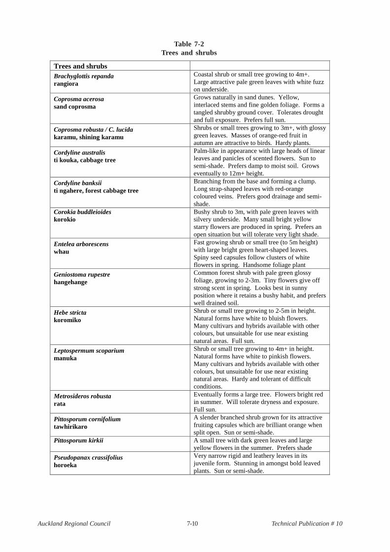
Trees and shrubs
Brachyglottis repanda rangiora
Coastal shrub or small tree growing to 4m+. Large attractive pale green leaves with white fuzz on underside.
Coprosma acerosa sand coprosma
Grows naturally in sand dunes. Yellow, interlaced stems and fine golden foliage. Forms a tangled shrubby ground cover. Tolerates drought and full exposure. Prefers full sun.
Coprosma robusta / C. lucida karamu, shining karamu
Shrubs or small trees growing to 3m+, with glossy green leaves. Masses of orange-red fruit in autumn are attractive to birds. Hardy plants.
Cordyline australis ti kouka, cabbage tree
Palm-like in appearance with large heads of linear leaves and panicles of scented flowers. Sun to semi-shade. Prefers damp to moist soil. Grows eventually to 12m+ height.
Cordyline banksii ti ngahere, forest cabbage tree
Branching from the base and forming a clump. Long strap-shaped leaves with red-orange coloured veins. Prefers good drainage and semi-shade.
Corokia buddleioides korokio
Bushy shrub to 3m, with pale green leaves with silvery underside. Many small bright yellow starry flowers are produced in spring. Prefers an open situation but will tolerate very light shade.
Entelea arborescens whau
Fast growing shrub or small tree (to 5m height) with large bright green heart-shaped leaves. Spiny seed capsules follow clusters of white flowers in spring. Handsome foliage plant
Geniostoma rupestre hangehange
Common forest shrub with pale green glossy foliage, growing to 2-3m. Tiny flowers give off strong scent in spring. Looks best in sunny position where it retains a bushy habit, and prefers well drained soil.
Hebe stricta koromiko
Shrub or small tree growing to 2-5m in height. Natural forms have white to bluish flowers. Many cultivars and hybrids available with other colours, but unsuitable for use near existing natural areas. Full sun.
Leptospermum scoparium manuka
Shrub or small tree growing to 4m+ in height. Natural forms have white to pinkish flowers. Many cultivars and hybrids available with other colours, but unsuitable for use near existing natural areas. Hardy and tolerant of difficult conditions.
Metrosideros robusta rata
Eventually forms a large tree. Flowers bright red in summer. Will tolerate dryness and exposure. Full sun.
Pittosporum cornifolium tawhirikaro
A slender branched shrub grown for its attractive fruiting capsules which are brilliant orange when split open. Sun or semi-shade.
Pittosporum kirkii A small tree with dark green leaves and large yellow flowers in the summer. Prefers shade
Pseudopanax crassifolius horoeka
Very narrow rigid and leathery leaves in its juvenile form. Stunning in amongst bold leaved plants. Sun or semi-shade.
Table 7-2Trees and shrubs
7-11Auckland Regional Council Technical Publication # 10
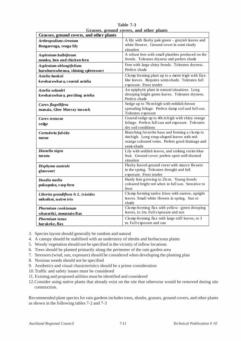
3. Species layout should generally be random and natural4. A canopy should be stabilised with an understory of shrubs and herbaceous plants5. Woody vegetation should not be specified in the vicinity of inflow locations6. Trees should be planted primarily along the perimeter of the rain garden area7. Stressors (wind, sun, exposure) should be considered when developing the planting plan8. Noxious weeds should not be specified9. Aesthetics and visual characteristics should be a prime consideration10. Traffic and safety issues must be considered11. Existing and proposed utilities must be identified and considered12.Consider using native plants that already exist on the site that otherwise would be removed during site
construction.
Recommended plant species for rain gardens includes trees, shrubs, grasses, ground covers, and other plantsas shown in the following tables 7-2 and 7-3
Grasses, ground covers, and other plantsArthropodium cirratumRengarenga, renga lily
A lily with fleshy pale green – greyish leaves andwhite flowers. Ground cover in semi shadysituation
Asplenium bulbiferummouku, hen and chicken fern
A robust fern with small plantlets produced on thefronds. Tolerates dryness and prefers shade
Asplenium oblongifoliumhuruhuruwhenua, shining spleenwort
Fern with large shiny fronds. Tolerates dryness.Prefers shade
Astelia banksiikowharawhara, coastal astelia
Clump forming plant up to a metre h igh with flax-like leaves. Requires semi-shade. Tolerates fullexposure. Frost tender
Astelia solandrikowharawhara, perching astelia
An epiphytic plant in natural situations. Longdrooping bright green leaves. Tolerates dryness.Prefers shade
Carex flagelliferamanaia, Glen Murray tussock
Sedge up to 70cm h igh with reddish-brownspreading foliage. Prefers damp soil and full sun.Tolerates exposure
Carex testaceasedge
Coastal sedge up to 40cm h igh with shiny orangefoliage. Prefers full sun and exposure. Toleratesdry soil conditions
Cortaderia fulvidatoetoe
Branching from the base and forming a clump to4m h igh. Long strap-shaped leaves with red-orange coloured veins. Prefers good drainage andsemi-shade
Dianella nigraturutu
Lily with reddish leaves, and striking vio let-bluefruit. Ground cover; prefers open well-drainedsituation
Disphyma australeglasswort
Fleshy leaved ground cover with mauve flowersin the spring. Tolerates drought and fullexposure. Frost tender
Doodia mediapukupuku, rasp fern
Hardy fern g rowing to 25cm. Young frondscoloured bright red when in full sun. Sensitive tofrost
Libertia grandiflora & L. ixioidesmikoikoi, native iris
Clump forming native irises with narrow, uprightleaves. Small white flowers in spring. Sun orshade
Phormium cookianumwharariki, mountain flax
Clump-forming flax with yellow –green droopingleaves, to 2m. Full exposure and sun
Phormium tenaxharakeke, flax
Clump-forming flax with large stiff leaves, to 3m. Fu ll exposure and sun
Table 7-3Grasses, ground covers, and other plants
7-12Auckland Regional Council Technical Publication # 10
7.6 Construction
7.6.1 Sand filters
Sand filters may involve reinforcing steel, concrete and significant site preparation and excavation beforeconstruction. The approved plans should be reviewed and discussed for any concerns at the preconstructionmeeting. The following construction times and items are important to recognise during the site inspection.
1. Stake out the filtration facility location.2. Generally, do not use filters for sediment control during construction.3. Pre-fabricated structural components should be available on-site to verify adequacy of materials.
Reinforcing bars should meet design specifications as should all other structural components such asany pipes, aggregate material and filter fabric.
4. Clear foundation areas of any organic material which could cause uneven settlement as the materialdecomposes. Unsuitable foundation material should be removed and replaced with suitable material.
5. Compact the foundation area to sustain the load placed on it by the filtration system. Level thefoundation as detailed on the plans to ensure proper drainage of the facility.
6. Ensure the ARC or TA inspector is on site when the facility has been formed up with reinforcing barsin place but before pouring the concrete so pouring can be observed.
7. During concrete pouring, the inspector must verify that the concrete meets design specifications forthe design load.
8. If the filtration practice is composed of prefabricated units, the inspector must approve the means ofjoining the sections and the steps taken to prevent leakage from between the prefabricated units.
9. Before backfilling, fill the filters with water once the concrete has set (or joints on prefabricated unitshave been sealed) and allowed to sit for 24 hours and observe whether the unit has any leaks.
10. When installation has been completed to meet size and volume requirements, has no leakage and thecontributing catchment areas have been stabilised, place the underdrains on the proper slope andwrap them in filter fabric to prevent migration of the filtration material out of the facility.
11. Place the filter material in the facility. The material should meet criteria specified on the design plans.The sand should be clean, washed aggregate. Other materials, such as peat or compost, may be-come more accepted if their performance demonstrates their value.
12. Conduct a final inspection to verify that the filter material is placed correctly and the first sedimentationchamber is clean of any accumulated sediments or other construction debris. Site inspection formsare at the end of the Chapter.
7.6.2 Rain gardens
1. Ideally, defer building the rain garden until after the contributing drainage area has been stabilised.2. Do not use the area excavated as a sediment ponding area during site construction, as finer sediments
may seal the bottom before it starts operation.3. Stake out the general location of the rain garden so that location and dimensions can be considered
in terms of site suitability.4. Excavate the rain garden and connet the underdrains to the stormwater drainage system. If there is
no stormwater system, the underdrain should be connected to a flow distribution system to avoidconcentrated flows downstream. Impervious lining or filter fabric should be placed at this time.
5. Place gravel backfill, sand backfill and planting soil in excavation. Verify composition of materialsand compaction.
6. Plant vegetation, lay mulch and complete site stabilisation.
7.6.3 As-built plans
Consent conditions may require an As-built plan to verify that construction was done in accordance with theapproved consent.

7-13Auckland Regional Council Technical Publication # 10
The As-built plan must verify the:
1. Dimensions and materials of the filtration system or rain garden match the design dimensions2. Filter material is per specification3. Inlets and outlets are constructed correctly4. Underdrains are installed to grade5. Prefabricated joints are sealed (filtration practice)6. 24 hour water test verified no leakage of filtration chamber (filtration practice)
7.7 Operation and maintenance
7.7.1 Sand filters
As is the case with all stormwater practices, the frequency of maintenance depends on the contaminantloadings entering the practice.
Two major components of sand filters include:
> a sedimentation chamber> a filtration chamber
Sedimentation chamber
The sedimentation chamber settles and stores coarser sediments and debris mainly by gravity. Maintenanceinspectors should ensure that the depth of stored materials is below the level where they will migrate to thefiltration chamber. This depth is relatively easy to measure.
Maintenance of the sedimentation chamber is generally not needed more than every two to ten years.Sedimentation chambers are normally wet, so the accumulated material is easily removed with vacuum typeequipment. Volumes to be removed are generally fairly, reflecting the smaller catchment areas these practicesserve. This makes vacuuming a practical method.
Access must be provided to the sedimentation chamber for entry and performance of maintenance.
Filtration chamber
Maintenance of filter chambers depends on the magnitude of the incoming contaminant loadings, but filtersgenerally require cleanout every 6 - 12 months.
The finer sediments may be raked from the surface of the sand and removed, or a flat bottom shovel mayskim off the surface of the sand to re-establish sand permeability.
Filtration chambers are more sensitive than sedimentation chambers to clogging by fine sediments and otherfine grained materials, such as oils and greases. While the sedimentation chamber functions primarily throughgravity settling of the incoming materials, the filtration chamber is where filtering of contaminants occurs.This chamber will be more effective at removal of the finer sediments, which are retained primarily in the top50 mm of the filter media.
Filtration chambers need more frequent maintenance than sedimentation chambers. If the sand filter is in anarea with a significant contaminant loading, filter maintenance may be needed at least twice per year toensure that the design flows travel through the practice. Diminished permeability of the sand will result inmore frequent overflows into the conventional drainage system with less stormwater treatment. It will befairly easy to see the depth of penetration of the contaminants and how much filter media needs removal.Usually, it is not necessary to replace all of the filter media, only the top layer.

7-14Auckland Regional Council Technical Publication # 10
When portions of the filter media must be replaced, only materials which meet the stormwater programme'sfilter specifications should be used. There is research being done with alternative filter media such as com-post, zeolite, fly ash, activated carbon, alum, and so on. If the ARC allows or specifies an alternative filtermedia as a replacement, this should be documented in the inspection and owner's files as a departure fromthe approved plans.
Vandalism
As with all stormwater management facilities, there is always the potential for vandalism. This can includedamage to the practice itself, theft of practice components or illegal dumping of waste products such aswaste oil. Planning is essential in order to enable prompt remedial action.
A primary method to reduce vandalism is a community education program explaining stormwater contaminantgeneration, the importance of stormwater practices such as filter systems and the need to limit contaminantentry into BMPs. One component of this education program could be stenciling of the inlets to the filter. Thismay prevent some misuse resulting from ignorance of the facility's purpose.
Other maintenance concerns such as scour, leakage, spalling of concrete or cracks in concrete and gratesneed to be addressed when they are discovered. If the normally wet sedimentation chambers become dry,there is leakage, and the leakage must be stopped for the facility to function correctly. If the leaking areacannot be identified, a dye test may be necessary to track the flow of water in the leaking chamber. Inaddition, concrete will deteriorate over time, especially if subject to live loads. The concrete must be routinelyinspected, and repaired when necessary.
7.7.2 Rain gardens
Rain gardens treat runoff by filtering it through vegetation and then passing it vertically through an organicsoil which filters the runoff. Besides vegetative filtration, treatment may, if designed for, rely upon infiltrationof runoff into underlying soils or to an underdrain.
Therefore, maintenance is primarily concerned with:
> Maintenance of flow to and through the biofilter> Maintaining planted vegetation and preventing undesired overgrowth vegetation from taking over the
area> Removal of accumulated sediments> Debris removal
Vegetation
Vegetation enhances rain garden performance for stormwater treatment and then requires close attention.Maintenance includes fertilising plants, removing noxious plants or weeds, re-establishing plants that die andmaintaining mulch cover.
Regular inspections by the responsible entity (TA, ARC, maintenance organisation) must be done to ensurethat the desired vegetation remains and is not overtaken by invasive undesirable plants. In some situations thereplacement of the planted vegetation by a volunteer species may be beneficial, but only if the invasivespecies provides equal or increased water quality benefits and is accepted by the owners of the site.
Sediment
Sediments accumulate in rain gardens and their removal may be the most expensive aspect of rain gardenmaintenance. Removal should occur when surface ponding lasts significantly longer than the one day draintime, which indicates surface clogging. When sediments are to be removed, it is essential to restore the

7-15Auckland Regional Council Technical Publication # 10
vegetation and soil conditions to the originally constructed condition. Sediment removal will necessitate dis-turbance of the vegetation, so steps will have to be taken to re-establish the vegetation upon completion ofsediment removal. Erosion control in the contributing drainage area also will be necessary to prevent scourand excessive sedimentation in the rain garden until there is once again a dense stand of vegetation.
Sediment may also impede effective performance of a rain garden by clogging the soil surface and preventingdesign storms from being treated. If stormwater backs up into the upstream drainage area, overflow mayoccur and bypass the treatment area.
Debris
Similar to other types of practices, debris removal is an ongoing maintenance function at all rain gardensystems. Debris, if not removed, can block inlets or outlets, and can be unsightly if located in a visiblelocation. Inspection and removal of debris should be done on a monthly basis, with debris also removedwhenever it is observed on site.
Just as it is important to know when a rain garden needs to be maintained, it is important to know whenmaintenance does not have to be done. The original plan for the site provides the best information at that timeon the design and construction of the rain garden. Over time the facility may change in appearance andfunction. These changes may not necessarily be bad. Having a knowledgeable inspector conduct regularinspections may be one way to allow a rain garden to evolve into an improved facility with reduced mainte-nance costs.
7.8 Case studies
7.8.1 Case study 1 - sand filter
A sand filter is to be constructed for a 2000 m2 carpark. Being a carpark, the impervious surface is 100% ofthe total area.
2-year 24-hour rainfall = 75 mm
1. Water quality storm extrapolation 75 mm for 2-year, 24 hour storm = 25 mm (75/3)2. From TP 108, the required water quality volume - WQV = 41.4 m3
3. Live storage provide = (0.37)(41.4) = 15.3 m3
4. Surface area of filterI
aHd
f (41.4)(0.4)
Af = = = 9.2 m2
k(h+df)t
f1(0.5+0.4)(2)
5. Sedimentation area = 9.2/4 = 2.3 m2
7.8.2 Case study 2 - rain garden
A rain garden is to be constructed on a residential property that is located in Kumeu. The total catchmentdraining to the rain garden is 1000 square metres of which 200 square metres is impervious surface.
1. Water quality storm extrapolation 81 mm of rainfall for 2 year, 24 hour storm = 27 mm2. From TP 108, calculated separately, the required water quality volume - WQV = 8.01 m3
3. Live storage to be provided = (0.4)(8.01)
3. (WQV)(df)
Af =
k(h+df)(t
f)

7-16Auckland Regional Council Technical Publication # 10
Af = (8.01 m3)(1m)/(0.3 m/day)(0.11m+1m)(1day)
Af = 24.0 m2
7.9 Bibliography
Claytor, R.A. and Schueler, T.R. Design of Stormwater Filtering Systems, prepared for Chesapeake Re-search Consortium, Inc., December 1996.
McKergow, L., Efficiency of an Urban Stormwater Filter, Unitec, Auckland, NZ, ARC Environment DivisionTechnical Publication No. 48, September, 1994.
Washington State Department of Ecology, Stormwater Management Manual for Western Washington, Vol-ume 5, Runoff Treatment BMP’s, Publications No. 99-15, August, 2001.
Coffman, L.S., Low-Impact Development Design: A New Paradigm for Stormwater Management Mimick-ing and Restoring the Natural Hydrologic Regime, Proceedings from the National Conference on Tools forUrban Water Resource Management & Protection, February, 2000.
Engineering Technologies Associates, Inc., Design Manual for Use of Biofiltration in Stormwater Manage-ment, Prince Georges County Government, June 8, 1993
Watershed Management Institute, Operation, Maintenance, & Management of Stormwater Management,August, 1997

7-17Auckland Regional Council Technical Publication # 10
Filtration systemInspection forms
Construction inspection forms
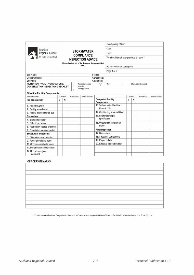
7-18Auckland Regional Council Technical Publication # 10
L:\Lr\stormwater\Revised Templates for Inspection\Construction Inspection Form\Filtration Facility Construction Inspection Form (1).doc
Investigating Officer:
Date:
Time:
Weather: Rainfall over previous 2-3 days?
Person contacted during visit:
STORMWATER COMPLIANCE
INSPECTION ADVICE
(Under Section 332 of the Resource Management Act
1991)
Page 1 of 2
Site Name: File No:
Consent Holder: Consent No:
Engineer: Catchment:
FILTRATION FACILITY OPERATION & CONSTRUCTION INSPECTION CHECKLIST
:
9
Needs immediate attention Not Applicable
V Okay ; Clarification Required
Filtration Facility Components: Items Inspected Checked Satisfactory Unsatisfactory Checked Satisfactory Unsatisfactory
Pre-construction Y N Completed Facility Components
Y N
1. Runoff diverted
2. Facility area cleared
13. 24 hour water filled test (if applicable)
3. Facility location staked out 14. Contributing area stabilised
Excavation
4. Size and Location
15. Filter material per specification
5. Side slopes stable
6. Foundation cleared of debris
16. Underdrains installed to grade
7. Foundation area compacted Final Inspection
Structural Components 17. Dimensions
8. Dimensions and materials 18. Structural Components
9. Forms adequately sized 19. Proper outlets
10. Concrete meets standards 20. Effective site stabilisation
11. Prefabricated joints sealed
12. Underdrains (size, materials)
OFFICERS REMARKS:

7-19Auckland Regional Council Technical Publication # 10
L:\Lr\stormwater\Revised Templates for Inspection\Construction Inspection Form\Filtration Facility Construction Inspection Form (1).doc
ACTION TO BE TAKEN:
No action necessary. Continue routine inspections? Y / N
Correct noted site deficiencies by ________________________________________________________________________________
1st Notice: _______________________________________________________________________________________
2nd Notice: _______________________________________________________________________________________
Submit plan modifications as noted in written comments by ____________________________________________________________
Notice to Comply issued ________________________________________________________________________________________
Final inspection, project completed ________________________________________________________________________________
Officers signature: _________________________________
Consent Holder/Engineer/Agent’s signature: __________________________________

7-20Auckland Regional Council Technical Publication # 10
Investigating Officer:
Date:
Time:
Weather: Rainfall over previous 2-3 days?
Person contacted during visit:
STORMWATER COMPLIANCE
INSPECTION ADVICE
(Under Section 332 of the Resource Management Act
1991)
Page 1 of 2
Site Name: File No:
Consent Holder: Consent No:
Engineer: Catchment:
RAIN GARDEN CONSTRUCTION INSPECTION FORM
:
9
Needs immediate attention
Not Applicable
V Okay ; Clarification Required
Rain Garden Construction Components:
Items Inspected Checked Satisfactory Unsatisfactory STRUCTURAL COMPONENTS Checked Satisfactory Unsatisfactory
PRE-CONSTRUCTION 11. Inflow & outlets installed correctly Y N
1. Runoff diverted Y N 12. Overflow system installed correctly Y N
2. Facility area cleared Y N 13. Pretreatment devices installed Y N
3. Facility location staked out Y N VEGETATION
4. Contributing drainage are stabilised Y N 11. Complies with planting specification Y N
EXCAVATION
5. Size & location Y N
12. Topsoil adequate in composition &
placement Y N
6. Excavated to appropriate grade Y N 13. Mulch laid Y N
7. Appropriate liners placed as required Y N FINAL INSPECTION
UNDERDRAINS & FILTER MEDIA 14. Dimensions Y N
15. Proper outlet Y N 8. Perforated underdrain installed correctly
Y N
16. Effective stand of vegetation & stabilisation
Y N
9. Storm drain system installed & connected
Y N 17. Construction generated sediments removed
Y N
10. Gravel, sand, & planting soil back backfilled
Y N
OFFICERS REMARKS:

7-21Auckland Regional Council Technical Publication # 10
ACTION TO BE TAKEN:
No action necessary. Continue routine inspections? Y / N
Correct noted site deficiencies by _____________________________________________________________________________
1st Notice: ___________________________________________________________________________________
2nd Notice: ___________________________________________________________________________________
Submit plan modifications as noted in written comments by _________________________________________________________
Notice to Comply issued ____________________________________________________________________________________
Final inspection, project completed ____________________________________________________________________________
Officers signature: _________________________________
Consent Holder/Engineer/Agent’s signature: __________________________________

7-22Auckland Regional Council Technical Publication # 10
Filtration systemInspection forms
Operation and maintenance
7-23Auckland Regional Council Technical Publication # 10
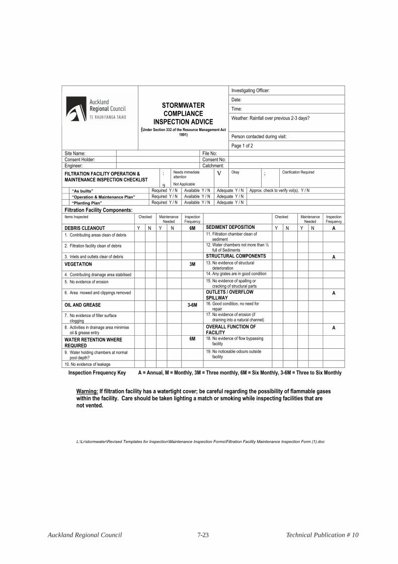
L:\Lr\stormwater\Revised Templates for Inspection\Maintenance Inspection Forms\Filtration Facility Maintenance Inspection Form (1).doc
Investigating Officer:
Date:
Time:
Weather: Rainfall over previous 2-3 days?
Person contacted during visit:
STORMWATER COMPLIANCE
INSPECTION ADVICE
(Under Section 332 of the Resource Management Act
1991)
Page 1 of 2
Site Name: File No:
Consent Holder: Consent No:
Engineer: Catchment:
FILTRATION FACILITY OPERATION & MAINTENANCE INSPECTION CHECKLIST
:
9
Needs immediate attention
Not Applicable
V Okay ; Clarification Required
“As builts” Required Y / N Available Y / N Adequate Y / N Approx. check to verify vol(s). Y / N
“Operation & Maintenance Plan” Required Y / N Available Y / N Adequate Y / N
“Planting Plan” Required Y / N Available Y / N Adequate Y / N
Filtration Facility Components: Items Inspected Checked Maintenance
Needed Inspection Frequency
Checked Maintenance Needed
Inspection Frequency
DEBRIS CLEANOUT Y N Y N 6M SEDIMENT DEPOSITION Y N Y N A
1. Contributing areas clean of debris 11. Filtration chamber clean of sediment
2. Filtration facility clean of debris 12. Water chambers not more than ½ full of Sediments
3. Inlets and outlets clear of debris STRUCTURAL COMPONENTS A
VEGETATION 3M 13. No evidence of structural deterioration
4. Contributing drainage area stabilised 14. Any grates are in good condition
5. No evidence of erosion 15. No evidence of spalling or cracking of structural parts
6. Area mowed and clippings removed OUTLETS / OVERFLOW SPILLWAY
A
OIL AND GREASE 3-6M 16. Good condition, no need for repair
7. No evidence of filter surface clogging
17. No evidence of erosion (if draining into a natural channel)
8. Activities in drainage area minimise oil & grease entry
OVERALL FUNCTION OF FACILITY
A
WATER RETENTION WHERE REQUIRED
6M 18. No evidence of flow bypassing facility
9. Water holding chambers at normal pool depth?
19. No noticeable odours outside facility
10. No evidence of leakage
Inspection Frequency Key A = Annual, M = Monthly, 3M = Three monthly, 6M = Six Monthly, 3-6M = Three to Six Monthly
Warning: If filtration facility has a watertight cover; be careful regarding the possibility of flammable gases within the facility. Care should be taken lighting a match or smoking while inspecting facilities that are not vented.

7-24Auckland Regional Council Technical Publication # 10
L:\Lr\stormwater\Revised Templates for Inspection\Maintenance Inspection Forms\Filtration Facility Maintenance Inspection Form (1).doc
OFFICERS REMARKS:
OVERALL CONDITION OF FACILITY:
In accordance with approved design plans? Y / N In accordance with As Built plans? Y / N
Maintenance required as detailed above? Y / N Compliance with other consent conditions? Y / N
Comments: ___________________________________________________________________________________
Dates by which maintenance must be completed: / /
Dates by which outstanding information as per consent conditions is required by: / /
Officers signature: _________________________________
Consent Holder/Engineer/Agent’s signature: _______________________________
7-25Auckland Regional Council Technical Publication # 10
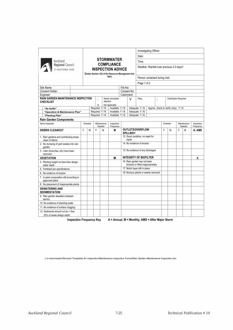
L:\Lr\stormwater\Revised Templates for Inspection\Maintenance Inspection Forms\Rain Garden Maintenance Inspection.doc
Investigating Officer:
Date:
Time:
Weather: Rainfall over previous 2-3 days?
Person contacted during visit:
STORMWATER COMPLIANCE
INSPECTION ADVICE
(Under Section 332 of the Resource Management Act
1991)
Page 1 of 2
Site Name: File No:
Consent Holder: Consent No:
Engineer: Catchment:
RAIN GARDEN MAINTENANCE INSPECTION CHECKLIST
:
9
Needs immediate attention
Not Applicable
V Okay ; Clarification Required
“As builts” Required Y / N Available Y / N Adequate Y / N Approx. check to verify vol(s). Y / N
“Operation & Maintenance Plan” Required Y / N Available Y / N Adequate Y / N
“Planting Plan” Required Y / N Available Y / N Adequate Y / N
Rain Garden Components: Items Inspected Checked Maintenance
Needed Inspection Frequency
Checked Maintenance Needed
Inspection Frequency
DEBRIS CLEANOUT Y N Y N M OUTLETS/OVERFLOW SPILLWAY
Y N Y N A, AMS
1. Rain gardens and contributing areas clean of debris
13. Good condition, no need for repair
2. No dumping of yard wastes into rain garden
14. No evidence of erosion
3. Litter (branches, etc) have been removed
15. No evidence of any blockages
VEGETATION M INTEGRITY OF BIOFILTER A
4. Planting height not less than design water depth
16. Rain garden has not been blocked or filled inappropriately
5. Fertilised per specifications 17. Mulch layer still in place
6. No evidence of erosion 18. Noxious plants or weeds removed
7. Is plant composition still according to approved plans
8. No placement of inappropriate plants
DEWATERING AND SEDIMENTATION
9. Rain garden dewaters between storms
10. No evidence of standing water
11. No evidence of surface clogging
12. Sediments should not be > than
20% of swale design depth
Inspection Frequency Key A = Annual, M = Monthly, AMS = After Major Storm

7-26Auckland Regional Council Technical Publication # 10
L:\Lr\stormwater\Revised Templates for Inspection\Maintenance Inspection Forms\Rain Garden Maintenance Inspection.doc
OFFICERS REMARKS:
OVERALL CONDITION OF FACILITY:
In accordance with approved design plans? Y / N In accordance with As Built plans? Y / N
Maintenance required as detailed above? Y / N Compliance with other consent conditions? Y / N
Comments: ___________________________________________________________________________________
Dates by which maintenance must be completed: / /
Dates by which outstanding information as per consent conditions is required by: / /
Officers signature: _________________________________
Consent Holder/Engineer/Agent’s signature: _______________________________