Embed Size (px)
Citation preview
EnvironmentalResource*Management, Inc.
97 October 1991? S55 S 'e Drive2J. UCtODer 1WJ Exton Pennsylvania 19.%Reference: EC334 00 " ^- (215)524-3500., AII r> j- !• ^-7 (215)524-7335(Fax)Vega Alta RemediationInitial Testing Program Plan
Mr. Jos6 FontVega Alta Project ManagerUnited States Environmental Protection AgencyCaribbean Field Office1413 Fernandez Juncos AvenueSanturce, PR 00909 ERM
Dear Mr. Font:
Environmental Resources Management, Inc. (ERM) is pleased to submit theenclosed revised Initial Testing Program (ITP) Plan (Plan) for the VegaAlta, Puerto Rico Remediation Site to The United States EnvironmentalProtection Agency (EPA). This Plan has been revised to comply with EPAcomments on ERM's earlier submittal of this same Plan, dated 3 August1993. The EPA comments were contained in a letter addressed to Mr. MarkE. Grummer, Esq., of Kirkland & Ellis from Carole Petersen, Chief, NewYork/Caribbean Superfuad Branch H, US EPA.
Please note that we continue to stamp this document DRAFT. When younotify us that you have approved the Plan, we will reissue it as a finaldocument.
If you have any questions regarding this submittal, please contact me at(215) 524-3776.
Sincerely,
Carl E. Petrus, P.E.Project Manager
enclosures: Four copies, Initial Testing Program, dated 22 October 1993cc: Denise Branch - The West Company
John R. Gailey, HI, Esq. - The West CompanyMark E. Grummer, Esq. - Kirkland & EllisGeorge J. Miller, Esq. - Dechert, Price, & Rhoads ^ P O Q A £Yaron M. Sternberg, PhD - Environ Corporation 1 J A. o U bDavid W. Thompson - General ElectricGloria Van der Heiden - Motorola
A member of the EnvirotunenU!Resources Management Croup
Initial Testing Program
Ponderosa Air Stripper SystemVega Alta, Puerto Rico
22 October 1993
DRAFT
Submitted To:
United States Environmental Protection AgencyCaribbean Held Office1413 Fernandez Juncos AvenueSanturce,PR 00909
Prepared By:
Environmental Resources Management, Inc.855 Springdale DriveExton, Pennsylvania 19341
ERM
102307
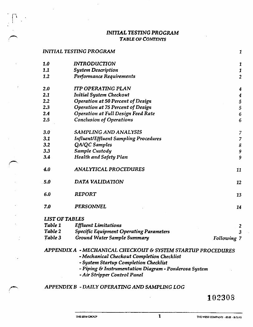
INITIAL TESTING PROGRAMTABLE OF CONTENTS
INITIAL TESTING PROGRAM 1
1.0 INTRODUCTION 11.1 System Description 11.2 Performance Requirements 2
2.0 JTP OPERATING PLAN 42.1 Initial System Checkout 42.2 Operation at 50 Percent of Design 523 Operation at 75 Percent of Design 52.4 Operation at Full Design Feed Rate 623 Conclusion of Operations 6
3.0 SAMPLING AND ANALYSIS 73.1 Influent/Effluent Sampling Procedures 73.2 QA/QC Samples 833 Sample Custody 93.4 Health and Safety Plan 9
4.0 ANALYTICAL PROCEDURES 11
5.0 DATA VALIDATION 12
6.0 REPORT 13
7.0 PERSONNEL 14
LIST OF TABLESTable 1 Effluent Limitations 2Table 2 Specific Equipment Operating Parameters 3TableS Ground Water Sample Summary Folloitring 7
APPENDIX A - MECHANICAL CHECKOUT & SYSTEM STARTUP PROCEDURES- Mechanical Checkout Completion Checklist- System Startup Completion Checklist- Piping & Instrumentation Diagram - Ponderosa System- Air Stripper Control Panel
APPENDIX B - DAILY OPERATING AND SAMPLING LOG
102308
THE ERM GROUT 1 THE WEST COMPANY - .00O\ - «/3/W
INITIAL TESTING PROGRAMPONDEROSA AIR STRIPPER SYSTEMVEGAALTA,PR
1.0 INTRODUCTION
This document describes the Initial Testing Program (ITP) to beundertaken for the purpose of testing and documenting the performanceof the Air Stripper System recently installed at the Ponderosa Well, locatedin Vega Alta, Puerto Rico. This Initial Testing Program Plan has beendeveloped to present the operation plans, sampling procedures, andquality assurance measures that will be used during the ITP. Theobjective of the ITP is to confirm that the ground water treatment systemat the former Puerto Rico Aqueduct and Sewer Authority (PRASA)production well reduces Volatile Organic Compounds (VOC) in thetreated effluent to the levels specified in the Order and provided inTable 1. The treated water will be discharged to Honda Creek during thisthree week test period. The ITP Plan also includes health and safetyissues, a listing of the personnel to be involved in the FTP, and adescription of the FTP Report to be prepared at the conclusion of the FTP.The FTP field activities are expected to be completed in three weeks.
The FTP Program will be performed by Environmental ResourcesManagement, Inc. (ERM), with the Construction Contractor, JaferConstruction, available on call in the event any mechanical or electricaldifficulties arise.
1.1 System Description
For a complete description of the Ponderosa Air Stripper System, thereader is referred to the Plans and Specifications contained in the FinalRemedial Design documents approved by the US EPA, dated 17 January1992. A brief description of the system is provided here for convenience:
The Ponderosa Air Stripper System consists of a submersible well pump,chemical pretreatment to reduce scaling, a packed air stripper column, an ^air supply blower, and a stripper bottoms pump. All equipment and opiping are housed in an insulated steel building for purposes of site ~'"5
security and noise attenuation. The upper portion of the stripper column ^protrudes through the roof of this building. The design capacity of thesystem is 600 gpm. The treated water can be discharged to either HondaCreek or to the water distribution system of the Puerto Rico Aqueduct andSewer Authority (PRASA). Provisions are included for the future
THEERMGHOUP 1 THEWESTCOMPANY-BC334.00.01-10/Z2/W
3.0 SAMPLING AND ANALYSIS
The sampling and analysis tasks proposed to accomplish the ITPOperating Plan are as follows:• The Site Engineer will collect influent and effluent samples from the
Ponderosa air stripper at varying flow rates (50%, 75%, and 100%)over a three week sampling period;
• A qualified laboratory will perform and report the sample analyses;• ERM will review and evaluate the data; and• ERM will prepare an ITP Report.
3.1 Influent/Effluent Sampling Procedures
The duration of the FTP will be completed within three weeks unless theanalytical results of the samples collected at the 50%, 75%, or 100% feedrates indicate that the system effluent does not meet the effluent limitationset forth in Table 1. The Site Engineer will be available to trouble-shootany problems which may arise in the field during operations. Table 3summarizes the number of samples to be collected at the various flowrates and other pertinent sampling and analysis information.
The ITP operations will commence with a system startup at 50% of thedesign water feed rate (300 gpm). Samples will be collected by the SiteEngineer from both the pre (influent) and post (effluent) treatment spigotson a daily basis for three consecutive days and analyzed for the TargetCompound List (TCL) Volatile Organic Compounds (VOCs) whichincludes the constituents listed in Table 1. Samples will be collected justprior to express shipping pickup and air-expressed to the laboratory on a24-hour turnaround time (TAT) basis.
If the analytical results from the 50% feed rate show that the specificconstituent effluent limitations presented in Table 1 have not beenexceeded, the feed rate will be increased to 75% of the design (450 gpm).
A Q . I n f l u e n t and effluent samples will be collected on a daily basis just before-* express shipping pickup for another three days at the 75% feed rate.
Samples will be collected for TCL VOCs and submitted to the laboratoryon a 24-hour TAT.
Based upon the results of the 75% feed rate samples, the rate will beincreased to 100% of the design flow (600 gpm). Daily sampling of theinfluent and effluent sample locations will be performed for another threedays to ensure that the required discharge limitations are not exceeded.
TKEERMOTOUP 7 TmvVESTCOMPAXY-ECJ34.00.m-lO/Z2/S-
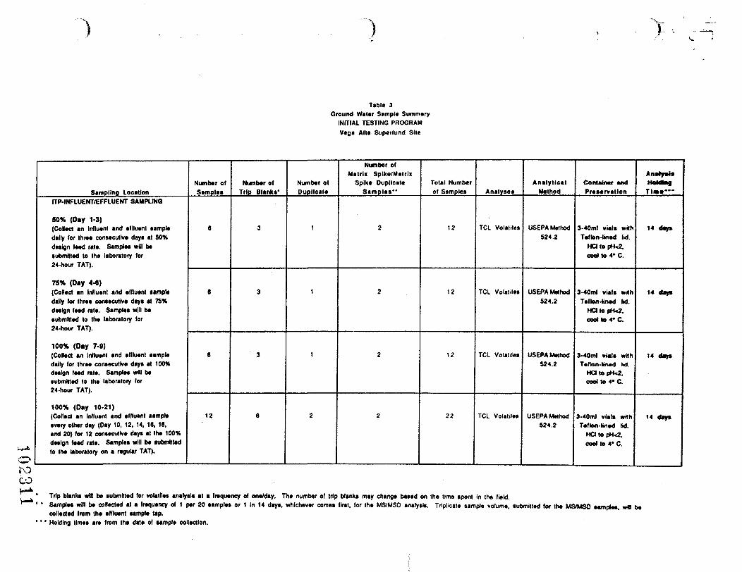
Table 3Ground Water Sample Summary
INITIAL TESTING PROGRAMVega Alia Superlund Site
Sampling LocationITP-INFLUENT/EFFLUENT SAMPLING
50% (Day 1-3)(Colled an Influent and affluent aampledally for three consecutive day* at 50%deaign feed rate. Samplea will be(ubmNted to the laboratory for24-hour TAT).
75% (Day 4-6)(Coifed an Influent and effluent sampledally for three contecutive day* at 75%deaign feed rate. Samplea will beeubmltted to the laboratory for24-hour TAT).
100% (Day 7-9)(Colled an Influent and effluent aampledally for three conaecutlve day* at 100%deaign feed rate. Samplea will beaubmltted to the laboratory for24-hour TAT).
100% (Day 10-21)(Colled an Influent and effluent aampleevery other day (Day 10. 12, 14, 18, 18,and 20) for 12 conteeulive daya at the 100%deaign feed rate. Samplea wHI be submittedto the laboratory on a regular TAT).
Number olSamples
6
8
6
12
Number ofTrip Blank*'
3
3
3
6
Number ofDuplicate
1
1
1
2
Number olMatrix Spike/Matrix
Spike DuplicateSamples"
2
2
2
2
Total Numberof Sample*
12
12
12
22
Analyse*
TCL Volatile*
TCL Volatile*
TCL Volatile*
TCL Volalilea
AnalyticalMethod
USEPA Method524.2
USEPA Method524.2
USEPA Method524.2
USEPA Method524.2
Container andPreservation
3-40ml vial* withTeflon-lined lid.
Hd to pH«2.cool to 4* C.
3-40ml vial* withTeflon-fined M.
HCttopH<2.cool to 4* C.
3-40ml vial* withTeflon-kned M.
HCMopH<2.cool to 4* C.
3-40ml vial* withTeflon-lined bd.
HO to pH<2.cool to 4* C.
Anatjr***HddtagTim**"
14 day*
14 day*
14 day*
14 day*
COTrip blank* wit! be submitted for volatile* analyslt at a frequency of one/day. The number of trip blanka may change baaed on ISamplea will be collected at a frequency of 1 par 20 aample* or 1 In 14 daya, whichever cornea flrat. for the MS/MSO analyst*,collected from the effluent sample tap.Holding tlmea are from the date of sample collection.
he time apent in the field.Triplicate sample volume, aubmitted for the MS/MSO aample*. wH be
Samples collected at 100% of the feed rate for the initial three day periodwill be submitted to the laboratory on a 24-hour TAT. Sampling will bereduced to every other day for the remaining 12 days of the Program andsubmitted to the laboratory on a regular TAT.
In order to procure representative samples from the influent and effluentlocations, the sample taps will be purged for one minute prior to samplecollection to flush the sample port After the sample tap is purged, theflow rate will be decreased to a low velocity so that samples can becollected without introducing air into the sample. Sample vials will becarefully filled to ensure that no air bubbles remain when capped. Theinfluent sample will be collected first, followed by the effluent sample.
To limit the potential for cross-contamination between samples, samplingpersonnel will wear clean, disposable surgical gloves for the collection ofeach sample. The samples will be placed in the laboratory-suppliedsample vials which will be preserved in the field with HC1, after samplecollection, in accordance with USEPA Region II CERCLA qualityassurance guidelines. The samples will then be labeled, logged on aChain-of-Custody Form, and placed in a cooler at 4°C for daily shipmentto Lancaster Laboratories, Inc., located in Lancaster, Pennsylvania.
Analytical results will be facsimiled to the ERM Sampling Coordinator inExton, Pennsylvania within two days of the sampling. The preliminaryresults will be reviewed and transmitted to the Site Engineer via afacsimile and/or telephone the same day that the results are received. TheSite Engineer will continue the ITP, as specified in Section 2, based uponthe expedited analytical results.
QA/QC Samples
Travel blanks will be submitted to the laboratory at a frequency of oneaqueous travel blank per shipment. A travel blank for ground waterconsists of sample bottles filled with laboratory demonstrated analy te-freewater. The purpose of collecting a quality control travel blank is to checkfor cross-contamination within sample shipment containers and forchanges occurring during shipping and the laboratory storage process.Travel blanks will be handled, transported, and analyzed in the samefashion as the regular samples, except that the travel blanks are notopened in the field. Travel blanks are designed to accompany the samplesto the laboratory and to be analyzed for TCL VOCs.
Blind duplicate samples will be collected to allow determination ofanalytical precision for the 50%, 75%, and 100% design capacity. Oneduplicate sample will be collected for every 20 samples. The duplicate
10233 2THE ERM CROUP 8 THEWESTCOMPAVY-EC334.00JI-10/'22/93
samples will be collected from the effluent of the treatment system andsubmitted to the laboratory for TCL VOC analysis.
Matrix spike/matrix spike duplicates (MS/MSD) will be submitted at afrequency of one per twenty samples or one in 14 days, whichever comesfirst. Triplicate sample volume will be collected from the influent samplelocation for the MS/MSD samples. The Site Engineer will designate theMS/MSD sample for quality control proposes and indicate thisinformation on the chain-of-custody sheet.
Samples collected during the various well water feed rates and submittedfor TCL VOCs will require a CLP data package to ensure accuracy andprecision of the sample results and to provide documentation for usabilityand qualification of the data.
3.3 Sample Custody
The primary objective of sample custody procedures is to create anaccurate written record which can be used to trace the possession andhandling of all samples from the moment of their collection, throughanalysis, until their final disposition.
Immediately after sample collection, sample bottles will be sealed inindividual plastic bags. Samples will then be placed immediately into aninsulated cooler for shipment to the laboratory. Chain-of-Custody recordswill accompany the samples inside the cooler for shipment to thelaboratory. Each cooler will contain sufficient ice and/or ice packs toensure that the temperature is properly maintained at 4°C and will bepacked in a manner to prevent damage to sample containers. Custody
; seals will be placed on the sample coolers to ensure sample integrityduring shipping. Samples will be shipped daily to the laboratory using anovernight delivery service.
3.4 Health and Safety Plan
A Health and Safety Plan (HASP), dated 11 May 1989, was included as anattachment to the approved Sampling, Analysis, and Monitoring Plan
1 C' 1 Q i o (SAMp) dated 19 February 1990 for the site. This HASP was developed as1 J «. o J u guidance for the level of protection required for site personnel conducting
field investigations at the site and will be used as part of the ITP. TheHASP is site-specific and is based on data collected during previousinvestigations and knowledge of the site. The HASP specifies the action
f, — N. levels that dictate the required level of safety apparel and workingprocedures appropriate for particular site conditions. Occupational Safetyand Health Administration (OSHA) 1910.120 regulations were followed in
THEERMCROUP 7 THEWESTCOMPAXY-ECmoom-iO/ZJ/n
the development of this plan. Personnel involved with the field samplingactivities will also be OSHA-certified under the same regulation.
102314
THE ERM CROUP 10 THE WEST COMPA.VY- K334.00.0l-10/Z2/S3
4.0 ANALYTICAL PROCEDURES
All ground water samples will be submitted for TCL VOCs. Theanalytical method which is to be used for the analysis of the sample mediacollected at the Site will be in accordance with US EPA ContractLaboratory Program (CLP) Statement of Work (SOW LCM01, datedJune 1991) for low level Organic Analyses. This method will use a 25 mlsample purge volume to achieve the quantitation limits needed toevaluate critical effluent discharge levels as required by the Order.
Analytical data for aqueous sample results will be reported as ug/L (ppb).Data packages associated with the TCL analyses of samples collectedduring the investigation will be prepared utilizing USEPA CLPdeliverable format.
102315
THE EXM GROUP 11 THE WEST COMPANY - BC3M.00.01 -10/ 22 rK
^ 5.0 DATA VALIDATION
After completion of the field activities and receipt of analytical data anddata packages, a quality assurance review of all data will be performed.The laboratory will supply the analytical results and Quality AssuranceData to allow validation of the analytical results. Chain-of-custodydocumentation, holding times, adherence to specified methods, internalstandard areas, surrogate compared recoveries, matrix spike/matrix spikerecoveries, initial and continuing calibrations, duplicate sample precision,instrument performance and raw data will be evaluated for conformancewith established criteria by a qualified chemist. The objective of thisvalidation process is to ascertain the validity of the results.
A Quality Assurance Report (QAR) will be prepared for all samplescollected after the completion of the data review and evaluation of thequalified and validated results. The report will indicate the analyses thatwere performed and the items evaluated during the data validationreview. Discrepancies, such as holding time issues, blank contaminants,etc., that are found during the review will be evaluated in terms of theimpact on the data usability. The QAR is then presented to the project
/*—* team to enable them to use the data with confidence. The QAR will beincluded in the final FTP Report.
102316
THEEXMCROUP 12 THEWESTCOMPANY-BCB4.00.D1-10/22/93
r"-
6.0 REPORT
The ITP Report, based on the operating and analytical data obtainedduring the FTP, will be prepared and submitted to USEPA within theAdministrative Order (Index No. H-CERCLA-90302) mandated 30calendar days from the completion of the ITP.
The report will consist of a complete descripdon of the ITP operations, adiscussion of any unusual operating difficulties, a presentation of thelaboratory analytical results (including a copy of the CLP deliverables),the QAR, and the certification of a registered professional engineer inPuerto Rico that the ground water treatment system has or has notreduced the VOC levels in the effluent to the required levels.
A preliminary Table of Contents follows:
Executive Summary
Introduction
Summary of Operations
Sampling Procedures Used
Discussion of Analytical Results
Conclusions
Attachments
Mechanical Checkout LogDaily Operating LogsQuality Assurance ReportAnalytical Results SheetsCLP Data Packages
102317THEERMGROUP 13 THEWESTCOMPANY-BC3M.00.01-10/22/W

7.0 PERSONNEL
The ItP Program will be coordinated by Carl E. Petrus, P.E., who has beeninvolved in both the design and construction review of the PonderosaSystem. Steven D. Glazier, P.E., will serve as the Site Engineer. Susan T.Barry will serve as the Sampling Coordinator, located in ERM's Exton, PAoffice. The sampling and analytical work will be reviewed and validatedby ERM's Quality Assurance Manager, Shawne Rodgers. Alan F. Hassett,P.E., will provide quality control of the FTP Program and will seal the ITPReport as a professional engineer registered in Puerto Rico.
0231 8
THE EKM GROUP 14 TOE WEST COMPANY- EC3J4.00B1-10/22/«
i n . -1 Appendix A
PROCEDURE OUTLINEMECHANICAL CHECKOUT &
SYSTEM STARTUP PROCEDURESPONDEROSA AIR STRIPPERVEGA ALTA REMEDIATION
22 October 1993
The following procedures will be used to perform the mechanicalcheckout and the startup of the Air Stripper System at the PonderosaWell in Vega Alta. The Mechanical Checkout (Part 1) will be performedjust prior to the start of the Initial Testing Program (ITP) to ensure thatall components of the System are in proper working order for the ITP.The System Startup Procedure (Part 2) will be used during theMechanical Checkout as well as during the operations phase of the ITP.
1 MECHANICAL CHECKOUTThe purpose of the Mechanical Checkout is to check the operation ofthe mechanical equipment, to confirm the calibration of the flow meter,and to verify that the shutdown interlocks and alarms work. Use thefollowing step-by step instructions for this test.1.1 Start the air blower by turning the Hand-Off-Auto (HOA) switch.
located on the face of the motor control center (MCC), to theHand position. There are two switches for each of the 480-voltmotors, an HOA switch on the MCC, and an Off-Auto Switch on theface of the Control Panel. The motor will always run in the Handposition of the MCC HOA switch, will not run in the Off position,and will be controlled by the Control Panel switch in the Autoposition of the MCC HOA Switch. Additionally, when the MCC HOASwitch is in the Auto position, the Off-Auto Switch on the ControlPanel will not permit the motor to run in the Off position, and willpermit the PLC program to decide if the motor runs in the Autoposition.Observe proper operation of Blower B-l and pressure gage PI-47on blower discharge. PI-47 should read about 1 inch WC with anew, clean packing bed in the Stripper. Allow the blower to runfor a minimum of 10 minutes, then stop it by turning the B-l MCCHOA switch to Off.
102319Appendix A - 1
1.2 Open the following valves:V-l, V-2, V-3, V-4, V-8, and V-10
1.3 Close the following valves:V-5, V-6, V-7. V-ll. and V-l 2The system valves are now properly set up to charge the stripperwith well water and to recirculate water from the bottom of thestripper to the top of the stripper with no net water flow throughthe system. During this initial filling of the system, the calibrationof Well Water Flow Meter FIT-39 will be checked for accuracy.This will be accomplished by manually setting Well Water FlowValve FV-39 to 40% open, starting Well Pump P-13. observing thetime it takes to raise the level in the sump three feet, andcomparing the calculated flowrate value to the observed flowratevalue indicated on Well Water Flow Indicator FI-39. Details of thisprocedure follow:
1.4 Place the MCC HOA Switch in Auto, and the Off-Auto SelectorSwitches on the Control Panel to Auto for Well Pump P-13 andBlower B-l. Place both switches for Stripper Effluent Pump P-5 inOff. to k^ep this pump from running.
1.5 Turn Valve FV-39 Manual-Auto Selector Switch to Manual, andregulate the output on the adjacent FV-39 Positioner Knob to 40%open.
1.6 Similarly, set Sump Level Control Valve LV-51 to 40% open, withits Manual-Auto Selector Switch in Manual.
1 . 7 Manually Start Chemical Agitator AG- 1 . Confirm that it has started .1.8 Set Well Pump P-13 Shutdown Delay to 2 minutes, by turning the
Timer Setting Knob and observing the proper reading on the WellPump Delay Timer Indicator.
1.9 Similarly set the Blower B-l Shutdown Delay to 5 minutes, usingthe Timer Setting Knob and the Delay Timer Indicator for theblower.
1.10 Set Chemical Feed Pump Speed Indicator to 30% by adjusting theChemical Pump Speed Setting Knob and observing the properreading on the Speed Indicator. Turn Chemical Pump wall switchto On and its variable frequency drive fVFD) to Auto. Hiis will linkthe rate of chemical addition to the well water flow rate.
Appendix A - 2
1.11 Press the Yellow PLC Alarm/Reset Light to reset the PLC. Thisstep will start Well Pump P-13, Metering Pump P-9, and Blower B-1. As the system fills with well water, observe the water level inthe level glass in the sump of the Stripper, and time its rate of risefrom a "zero" point near the bottom of the glass to a point 3'-0"higher. At the same time, observe the reading, in gallons perminute (gpm) on Well Water Flow Indicator FI-39. Record bothobservations in the log. The 3"-0" rise in level is equivalent to 634gallons. Calculate the average gpm by dividing the 634 gallonsvolume by the observed filling time, in minutes. This calculatedrate should be within 5 percent of the reading observed on FI-39.
1.12 Confirm that Well Pump P-13 stops when the water level reacheshigh-high level switch (LSHH-50) in the Stripper Sump.
1.13 After confirming that the blower was running during this initialfilling Step 1.11, open V-5 and allow the treated water in thesump to drain by gravity to Honda Creek. When the sump level hasstabilized, close V-5.
1.14 Place both the MCC HOA Switch and the Off-Auto Selector Switch/*"""•*•• for Stripper Effluent Pump P-5 in Auto. Restart the System by
pressing the yellow PLC Alarm/Reset Light, starting P-13, P-9, andBlower B-l.
1.15 Confirm that Stripper Bottoms Pump P-5 starts when the sumpwater level rises above high level switch LSH-49. Water will berecirculating from the bottom of the stripper to the water inlet.with Blower B- 1 running at this time, ensuring that the water isbeing stripped of volatile organic compounds (VOCs) by the airfrom Blower B-l.
1.16 Confirm that Metering Pump P-9 starts with Well Pump P-13 andstops when P-13 stops.
1.17 Stop Well Pump P-13 when the sump level reaches approximately24. inches. Confirm that Blower B-l stops 5 minutes later.
1.18 Approximately 3 minutes after F-13 has stopped, but 2 minutesbefore Blower B-l is set to stop, slowly open Manual Valve V-5,permitting the stripped water to leave the system and dischargeto Honda Creek. Manually regulate the % open of LV-51, ifnecessary, by using the valve controls on the Control Panel, if it isdetected that the discharge rate is too low or too high. Observethat P-5 stops at low sump level LSL-43 set point. Prevent BlowerTimer from timing out before this test is complete by increasingBlower Tinier Delay setting, if necessary.
. 1 , . *-.Appendix A - 3
2 SYSTEM STARTUPThis test Is to confirm that the System performs properly during a
' normal startup of the System, as will be performed normally by theSystem Operator. This same procedure will be used during thestartup and normal operation portion of the FTP. Use thefollowing step-by-step instructions for this portion of the test.
2.1 Place all MCC HOA switches to Auto and all Control Panel MotorOff-Auto Selector Switches to Off.
2.2 Open the following valves:V-l. V-2, V-3, V-5. V-8, and V-10.
2.3 Close the following valves:V-4, V-6, V-7, V-ll, and V-12.The valve positions listed in 2.2 and 2.3 will result in discharge ofthe treated water to Honda Creek.
2.4 Set Well Water Flow Controller FIC-39 to 300 gpm. To change the_^ setpoint, if it is presently set at a flow value different than 300
gpm, use the following procedure:2.4.1 Push "SEL" key until SV (setpoint variable) is indicated on
the display.2.4.2 Push "DATA" key once.2.4.3 Use the A key to select which of the three digits are to be
changed (i.e., front of panel - left to right A A A).A A A 100 digit keyA A A 10 digit keyA A A i digit key
The appropriate digit will flash when selected.The A key for each position increases the value for thatposition, the v key decreases the value for each of the A
digit positions.2.4.4 Repeat as necessary until desired set point value is
displayed.2.4.5 Push "ENT" (enter) key to store the new set point value.
102322Appendix A - 4
2.5 Set Stripper Sump Level Controller LIC-51 to 18 inches, which isapproximately the mid-point of the level glass mounted on thestripper sump, using the same procedure outlined above in Part2.4 for FIC-39. At this time, the Valve Manual-Auto SelectorSwitches for both FV-39 and LV-51 should remain in Manualposition, with the output to each valve set at 40% open.
2.6 Set Well Pump P-13 Shutdown Delay to 2 minutes, by turning theTimer Setting Knob and observing the proper reading on the WellPump Delay Timer Indicator.
2.7 Similarly set the Blower B-l Shutdown Delay to 5 minutes, usingthe Timer Setting Knob and the Delay Timer Indicator for theblower.
2.8 Place the PLC Selector Switch to Auto position. Confirm that theyellow light goes out.
2.9 Set Chemical Feed Pump Speed Indicator to 30% by adjusting theChemical Pump Speed Setting Knob and observing the properreading on the Speed Indicator. Set the variable displacement dialon the pump to 10. Turn Chemical Pump wall switch to On and itsvariable frequency drive (VFD) to Auto. This will link the rate ofchemical addition to the well water flow rate.
2.10 Manually Start Chemical Agitator AG-1.2.11 Place the Off-Auto Switches on the Control Panel in Auto for P-13,
P-5. and B-l.2.12 Press the Yellow PLC Alarm/Reset Light to reset the PLC. This
step will start Well Pump P-13, Metering Pump P-9, and Blower B-1. As the system fills with well water, observe the water levelincrease in the level glass in the sump of the Stripper. StripperBottoms Pump P-5 will start at the LSH-49 set point. Read theactual water level, in inches, on the process variable display of LIC-51 (red indicator), and adjust the water level manually, using theLV-51 Positioner Knob, until the Process Variable (red indicator)is equal to the Set Point (green indicator). At this point, quicklytransfer the LV-51 Manual-Auto Selector Switch from Manual toAuto, for a "bumpless transfer".
2.13 Read the actual flow, in gpm, on the process variable display ofFIC-39. Adjust the actual flow, using the FV-39 Positioner Knob,until the Process Variable is equal to the Set Point (initially 300gpm). At this point, quickly transfer the FV-39 Manual-AutoSelector Switch from Manual to Auto, for a "bumpless transfer".
Appendix A - 5 182323
2.14 At this point, the System is on-line, processing 300 gpm of wellwater. Check all equipment for proper operation, examining forunusual noises, vibrations, leaks, etc. Confirm that the feedflowrate and level control are maintaining their chosen setpoints.Confirm that Metering Pump P-9 is dosing chemical reagent at aspeed of 15 %. Allow the system to run for a minimum of 1/2hour during this system check.
2.15 To change the well water flow rate, use the following procedure:2.15.1 Change FV-39 Manual-Auto Selector Switch from Auto to
Manual. This will retain the well water flow rate at itsprevious rate.
2.15.2 Push "SEL" key until SV (setpoint variable) is indicated onthe display.
2.15.3 Push "DATA" key once.2.15.4 Use the A key to select which of the three digits are to be
changed (i.e.. front of panel - left to right A A A).A A A 100 digit keyA A A 10 digit keyA A A 1 digit keyThe appropriate digit will flash when selected.The A key for each position increases the value for thatposition. The v key decreases the value for each of the A
digit positions.2.15.5 Repeat as necessary until the new desired set point value is
displayed.2.15.6 Push "ENT (enter) key to store the new set point value.2.15.7 Manually adjust the FV-39 Positioner Knob until the .
Process Variable (well water flow rate) equals the new setpoint value, then quickly switch FV-39 Manual-AutoSelector Switch to Auto. The System will then beprocessing the new well water flow rate. The StripperSump level will be automatically controlled at its set pointby LIC-51, maintaining the water leaving the Systemthrough LV-51 equal to the water entering the Systemthrough FV-39. Avoid abrupt changes in adjusting the FV-
Appendix A - 6
39 Positioner Knob, to allow Sump Level Controller LIC-51to adjust to the new flow through the system.
2.16 Confirm that Metering Pump P-9 speed has changed in proportionto the well water flow rate.
2.17 During the initial startup and checkout of the System, but notnecessarily on subsequent startups, confirm that the followingactions occur:2.17.1 If P-9 stops. Well Pump P-13 stops after time delay of 2
minutes. (P-9 failure can be simulated by turning the P-9switch to Off)
2.17.2 PSL-22 stops Well Pump P-13 on low pressure. (Can besimulated by stopping Blower B-1 (putting B-1 MCC HOA inOff), or by disconnecting leads on PSL-22)
2.17.3 Demonstrate proper operation of PCV-8 by closing V-10and observing that Sump level is maintained at its set pointduring a well water feed rate of 600 gpm. Confirm that thepressure reading on PI-15 during this operation is 110psig.
2.17 A After treated water is being accepted by The Puerto RicoAqueduct and Sewer Authority (PRASA), confirm that FI-40indicates the identical flow rate as Well Water Flow MeterFI-39, and that FQI-40 accurately shows the accumulativetotal gallons to date.
2.17.5 Measure and record the current draw per phase for WellPump P-13, Blower B-l, and Stripper Bottoms Pump P-5.These values should be approximately 50. 10, and 80 amps,respectively.
2.18 To shutdown the entire system at any time, turn either the MCCHOA or the Off-Auto Switch for Well Pump P-13 to "Off andobserve that all motors stop after the appropriate time delays.
102325
Appendix A - 7
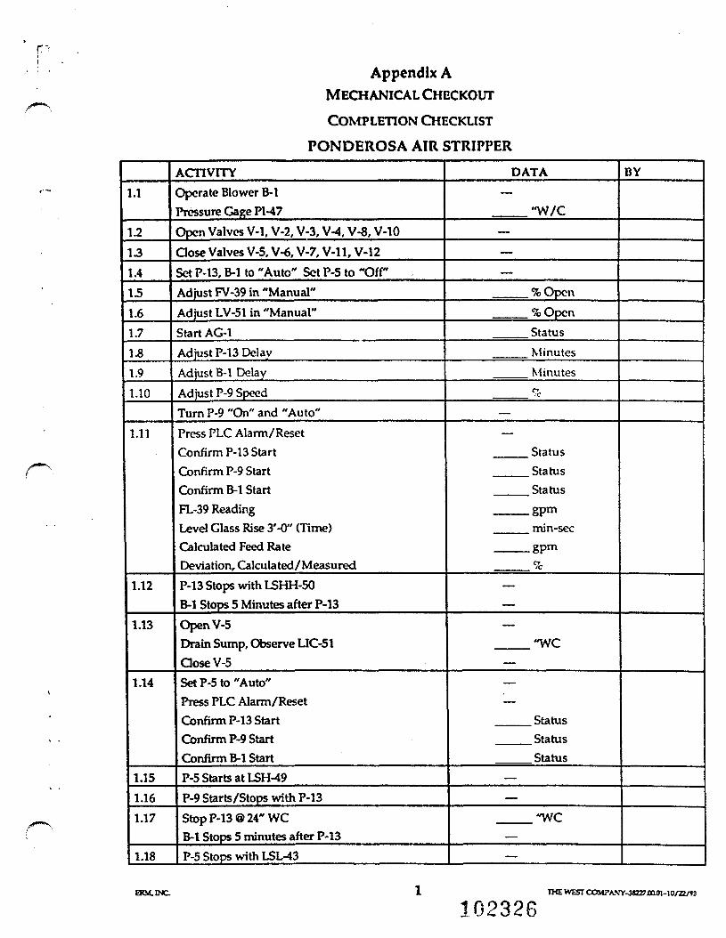
Appendix AMECHANICAL CHECKOUTCOMPLETION CHECKLIST
PONDEROSA AIR STRIPPER
1.1
1.2131.4151.61.71.81.91.10
1.11
1.12
1.13
1.14
1.151.161.17
1.18
ACTIVITYOperate Blower B-lPressure Gage PI-47Open Valves V-1, V-2, V-3, V-4, V-8, V-10dose Valves V-5, V-6, V-7, V-11, V-12Set P-13, B-l to "Auto" Set P-5 to "Off"Adjust FV-39 in "Manual"Adjust LV-51 in "Manual"Start AG-1Adjust P-13 DelayAdjust B-l DelayAdjust P-9 SpeedTurn P-9 "On" and "Auto"Press PLC Alarm/ResetConfirm P-13 StartConfirm P-9 StartConfirm B-l StartFL-39 ReadingLevel Glass Rise 3'-0" (Time)Calculated Feed RateDeviation, Calculated/ MeasuredP-13 Stops with LSHH-50B-l Stops 5 Minutes after P-13Open V-5Drain Sump, Observe UC-51dose V-5Set P-5 to "Auto"Press PLC Alarm/ResetConfirm P-13 StartConfirm P-9 StartConfirm B-l StartP-5 Starts at LSH-49P-9 Starts/Stops with P-13Stop P-13 @ 24" WCB-l Stops 5 minutes after P-13P-5 Stops with LSL^t3
DATA
"W/C———
%Opcn%OpenStatusMinutesMinutes%
—
StatusStatus
___ Status___ gpm
min-secgpm%
—
"WC—
StatusStatusStatus
——
"WC—
—
BY
ERM.INC.
102326THE WEST COMPANY-3«227.0a01-10/Z2/*J

rAppendix A
SYSTEM STARTUPCOMPLETION CHECKLIST
PONDEROSA AIR STRIPPER
2.1
2.2232.4
25
2.62.72.82.9
2.102.112.12
2.132.14
2.15
2.162.17
2.18
2.19
ACTIVITYConfirm MCC HOA in AUTOConfirm Off-Auto Switches in OffOpen Valves V-l, V-2, V-3, V-4, V-8, V-10dose Valves V-5, V-6, V-7, V-ll. V-12Adjust FIC-39 Set Point in 300 gpmFV-39 Output in "Manual"Adjust LIC-51 Set Point to 18 inchesLV-51 Output in "ManualAdjust P-13 DelayAdjust B-l DealyPLC Select "Auto"Adjust P-9 SpeedTurn P-9 "On" and "Auto"Start AG-1P-5, P-13, B-l Off-Manual Switch in "Auto"Press PLC Alarn/ResetConfirm P-13 RunningConfirm P-9 RunningConfirm B-l RunningConfirm P-5 Starts with LSH-49Transfer LV-51 to "Auto"Transfer FV-39 to "Auto"Confirm Steady-State OperationConfirm P-9 SpeedIncrease FIC-39 Set Point to 450 gpmConfirm UC-51 Process VariableConfirm P-9 Speed is 225%P-13 Stops 2 minutes after P-9P-13 Stops with PSL-22 FallingPCV Operates Successfully @ 110 psig (PI-15)Current Draw, P-5, Phase 1/2/3Current Draw, P-13, Phase 1/2/3Current Draw, B-l, Phase 1/2/3Demonstrate System Shutdown(Stop P-13)
DATA——..._.
——— 6Pm
___ inches
MinutesMinutesLif>ht
___ % Speed
Status—
Light Off___ Status___ Status
Status—
—
%_____ gpm
inches%
PSig__ /___/__ amps__ / _ / _ amps_ / _ / _ amps
—
BY
102327DM. INC. IHE WEST COMPA.VY-JGZ7.0C.01 -10/22/«

CW*CTIM n U UMONXANk U.
«. AbO MinMM CCMKACTfiM
VEGA ALTAGROUM> WRRM REMEDMCTW
PIPING a INSTRUMENTATION DIAGRAMPONDEROSA
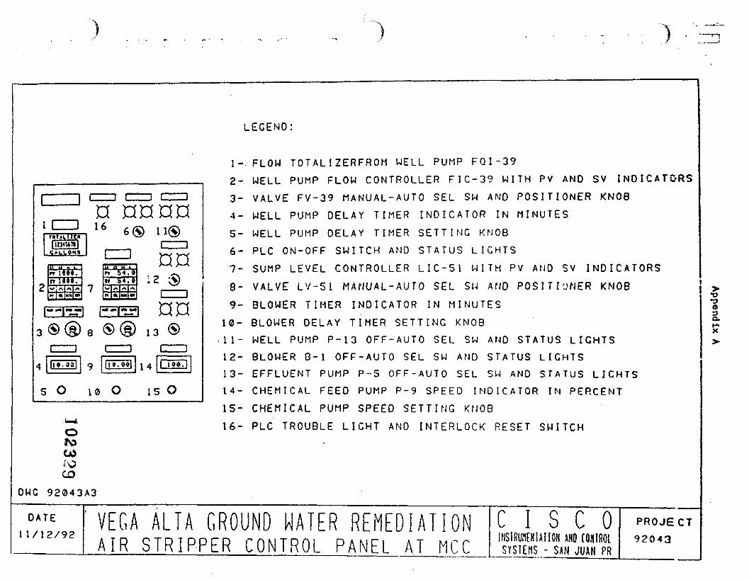
LEGEND:
ICH3a nnan16
s O 10 O is O
1-. FLOW TOTALIZERFROM WELL PUMP FQ1-392- WELL PUMP FLOW CONTROLLER FIC-39 WITH PV AND SV INDICATORS
3- VALVE FV-39 MANUAL-AUTO SEL SW AND POSITIONER KNOB4- WELL PUMP DELAY TIMER INDICATOR IN MINUTES
5- WELL PUMP DELAY TIMER SETTING KNOB6- PLC ON-OFF SWITCH AND STATUS LIGHTS
7- SUMP LEVEL CONTROLLER LIC-51 W I T H PV AND SV INDICATORS8- VALVE LV-Sl MANUAL-AUTO SEL SU AND POSITIONER KNOB9- BLOWER TIMER INDICATOR IN MINUTES
10- BLOWER DELAY TIMER SETTING KNOB• 1 1 - WELL PUMP P-13 OFF-AUTO SEL SW AND STATUS LIGHTSL2- BLOWER B-l OFF-AUTO SEL SW AND STATUS LIGHTS13- EFFLUENT PUMP P-5 OFF-AUTO SEL SW AND STATUS LIGHTS14- CHEMICAL FEED PUMP P-9 SPEED INDICATOR IN PERCENT
15- CHEMICAL PUMP SPEED SETTING KNOB16- PLC TROUBLE LIGHT AND INTERLOCK RESET SWITCH
(63O.H-X
CODWG 92043A3
D A T E11/12/92
VEGA ALTA GROUND WATER REHEDIATIONA I R S T R I P P E R C O N T R O L PANEL A T M C C
C I S C OINSIRUNCNIAUON AND (OXIROlSYSIEHS - SAN JUAN PR
PROJECT92043
' j
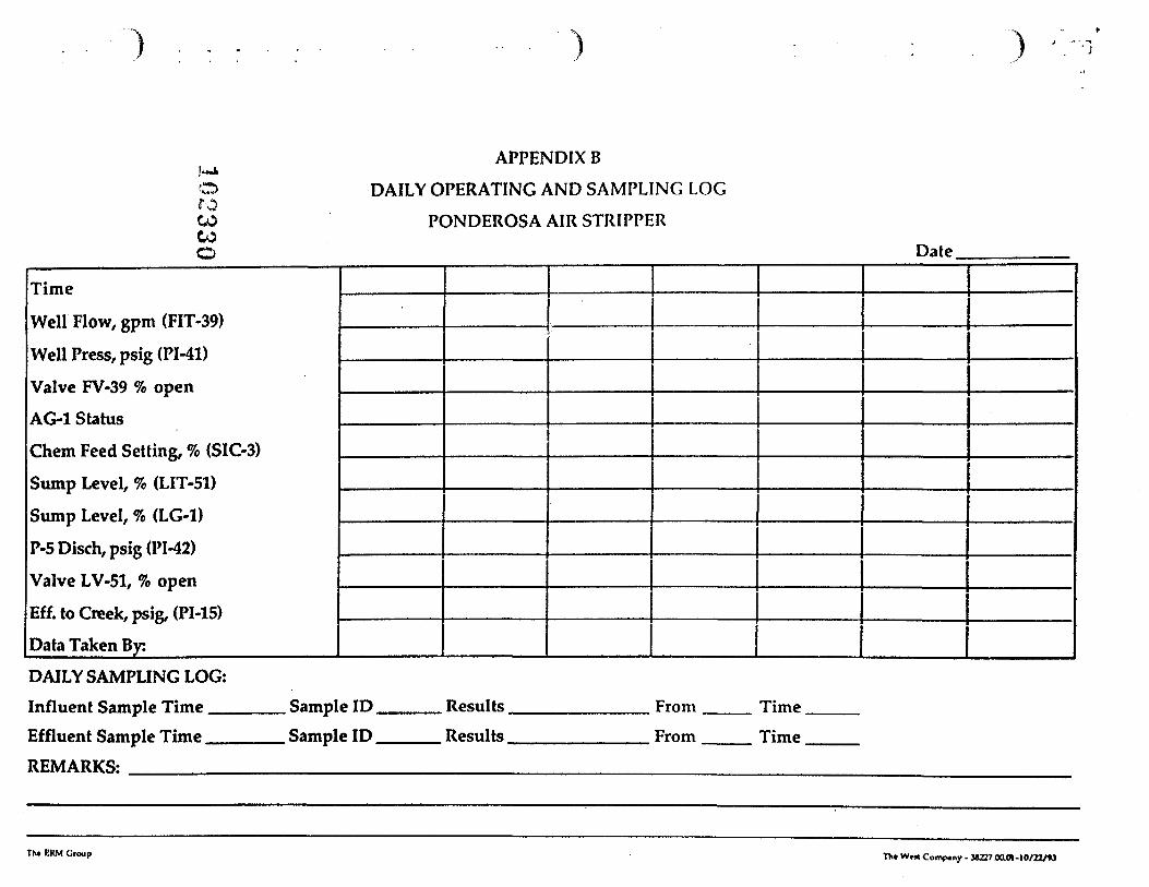
APPENDIX B!**jk0 DAILY OPERATING AND SAMPLING LOGCOCO PONDEROSA AIR STRIPPERCOO Date
TimeWell Flow, gpm (FIT-39)Well Press, psig (PI-41)Valve FV-39 % openAG-1 StatusChem Feed Setting, % (SIC-3)Sump Level, % (LIT-51)
Sump Level, % (LG-1)P-5Disch,psig (PI-42)
Valve LV-51, % openEff. to Creek, psig, (PI-15)Data Taken By:DAILY SAMPLING LOG:Influent Sample Time Sample ID Results From Time
Effluent Sample Time Sample ID Results From Time
REMARKS:
Th. EKM Croup T*« Ww< Compiny . MZ27OaOI-IO/ZZ/«J