Embed Size (px)
Citation preview

ENVIRONMENTAL IMPACT ASSESSMENT REPORT
4 X 700 MW PHWR HARAYANA ATOMIC POWER PROJECT (HAPP)
AT GORAKHPUR HARAYANA
VOLUME I : MAIN REPORT
MECON LIMITED RANCHI – 834 002 (JHARKHAND)
NUCLEAR POWER CORPORATION OF INDIA LIMITED (NPCIL) Nabhikiya Urja Bhavan, Anushaktinagar, Mumbai – 400094
11.S2.Q6SY May 2012


UNDERTAKING
I hereby undertake that prescribed TOR with respect to EIA/EMP Studies for Haryana Atomic Power Project (“Nuclear power projects and processing of nuclear fuel”) located near Gorakhpur Village, Bhuna Block, Tehsil, Sub-division and District Fatehabad, Haryana has been complied while conducting the EIA studies. The contents (information and data) as given by our consultant in the EIA report are factually correct, with full knowledge of the undersigned. Date: Signature of the applicant* with
full name & address
Place: [* Owner or his authorized signatory]
Given under the seal of organization on
behalf of whom the applicant is signing


Declaration by Experts Contributing to the EIA for Haryana Atomic Power Project
We hereby certify that we were a part of the EIA team in the following capacity that developed the above EIA. EIA Co-ordinator:
Name:
Signature & Date:
Period of Involvement: Contact Information:
Dr. Shailendra K. Singh
November 2010 till date. Ph: 9431767527; e-mail: [email protected]
Functional Area Experts SN. Functional
Areas Name of Expert Involvement
(Period & Task) Signature &
Date
1 AP C.D. Goswami March 2011 – Sept 2011 Air Pollution control strategy.
2 WP Dr. S.C. Jain March 2011 – Sept 2011 Water Pollution control strategy.
3 SHW 4 RH
Sanjay Sen March 2011 – Sept 2011 Solid waste disposal strategy,
Risk Assessment
5 SE Dr. S. Bhattacharya March 2011 – Sept 2011 Socio-economic studies.
6 EB Dr. S.K. Singh March 2011 – Sept 2011 Overall coordination and
Ecological studies.
7 HG Dr. S Veezhinathan March 2011 – Sept 2011 Hydro-geological studies.
8 GS A.K. Mishra March 2011 – Sept 2011
Geological studies. 9 AQ Dr. V.V.S.N.
Pinakapani March 2011 – Sept 2011
Meteorological and Air Pollution Dispersion studies.
10 NV Dr. Vikas Kumar March 2011 – Sept 2011 Noise control strategy.
SN. Functional Areas
Name of Expert Involvement (Period & Task)
Signature & Date
11 LU Dr. M.K. Mukhopadhyay
Palash Banerjee Vishal Skaria
March 2011 – Sept 2011 Land use studies.
March 2011 – Sept 2011
Land use studies.
March 2011 – Sept 2011 Land use studies.
Declaration by the Accredited Consultant Organization
I, Dr. Vikas Kumar, hereby confirm that the above mentioned experts prepared the EIA for Proposed Haryana Atomic Power Project. I also confirm that I shall be fully accountable for any misleading information mentioned in this statement.
Signature: Name: Dr. Vikas Kumar Designation: Dy. General Manager, Environmental Engineering Section Name of the EIA Consultant Organization: MECON Limited NABET Certificate No. & Issue Date: NABET/EIA/1013/031 dated, Oct., 01, 2010

ENVIRONMENTAL IMPACT ASSESSMENT REPORT
4 X 700 MW PHWR HARYANA ATOMIC POWER PROJECT AT GORAKHPUR, HARYANA
© 2012 MECON Limited. All rights reserved Page (i)
CONTENTS OF VOLUME I Item No. Particulars Page No. List of Tables viii List of Figures xii List of Drawing xiv Contents to Volume II xiv Index to MoEF TOR Coverage in EIA Report xv Abbreviations xx Summary EIA Es 1 – Es 13 1. Introduction 1 1.1 General 1 1.2 Purpose of the EIA Report 1 1.3 Identification of the Project and Project Proponent 1 1.3.1 The Project 1 1.3.2 Project Proponent 2 1.4 Statutory Requirements 2 1.4.1 Role of AERB on Establishment of Nuclear Power Project 2 1.4.2 Consent for Siting for the Proposed Project 3 1.5 Project Brief 7 1.5.1 Importance of the Project 7 1.5.2 Background 8 1.5.3 Location of the Project 8 1.5.4 Nature and Size of the Project 8 1.6 Scope of the EIA Study 8 1.7 Basic Data Generation, Field Studies and Data Collection 13 1.8 Structure of the EIA Report 13 2. Project Description 15 Section-I: Project Description 15 2.1 Introduction 15 2.2 Type of Project 15 2.3 Need of the Project 15 2.4 Site Selection Considerations 15 2.5 Project Location 18 2.6 Land Requirement 20 2.6.1 Land Area 20
2.6.2 Resettlement and Rehabilitation of PAPs for the Land under Acquisition Process 20
2.6.3 Land Acquisition 21 2.7 Size or Magnitude of Operation 21 2.8 Proposed Schedule for Approval and Implementation 21 2.9 Manpower Planning 22 2.10 Technology / Process Description 22 2.10.1 Salient Features 22 2.10.2 Engineering 22 2.11 Project Details 22 2.11.1 Safety Objectives and Principles 22 2.11.2 Barriers to Radioactivity Release 25 2.11.3 Special Safety Requirements 26 2.11.4 Safety Classification 27 2.11.5 General Design Criterion 29

ENVIRONMENTAL IMPACT ASSESSMENT REPORT
4 X 700 MW PHWR HARYANA ATOMIC POWER PROJECT AT GORAKHPUR, HARYANA
© 2012 MECON Limited. All rights reserved Page (ii)
Item No. Particulars Page No. 2.12 Reactor Process Systems 34 2.12.1 Reactor Physics 34 2.12.2 Reactor Fuel 36 2.12.3 Reactor Core Systems 37 2.12.4 Reactivity Devices 42 2.12.5 Moderator Liquid Poison Addition System 45 2.12.6 Primary Heat Transport System 45 2.12.7 Moderator System 47 2.12.8 End Shield and Calandria Vault Cooling Systems 49 2.12.9 CO2 Annulus Gas System 49 2,12,10 Secondary Systems 50 2.12.11 Fuel Handling and Control System 50 2.12.12 Instrumentation and Control (I&C) 51 2.12.13 Electrical System 55 2.12.14 Plant Auxiliaries 57 2.12.15 Design Life 64 2.13 Reactor Safety Systems 64 2.13.1 Shutdown Systems 64 2.13.2 Containment 65 2.13.3 Containment Spray System 66 2.13.4 Secondary Containment Recirculation and Purge 66 2.13.5 Primary Containment Controlled Discharge System (PCCD) 67 2.13.6 Fire Protection System 67 2.13.7 Emergency Core Cooling System (ECCS) 68 2.13.8 Ultimate Heat Sink 69 2.13.9 Overall Risk to the Public 69 2.14 Radiological Protection 69 2.14.1 Radiation Levels and Access Control 69 2.14.2 Contamination Control 70 2.14.3 Radiation Monitoring 71 2.14.4 Environmental Monitoring 71 2.14.5 Effluent Release Criteria 72 2.15 Radio Active Waste Management 72 2.15.1 Radioactive Waste Management Plant 72 2.15.2 Treatment and Discharge of Gaseous Effluent Stream 72 2.15.3 Permissible Gaseous Discharges 73 2.15.4 Radioactive Liquid Waste Management System 73 2.15.5 Discharge Limits 78 2.15.6 Solid Waste Management 81 2.16 Safety Analysis 85 2.17 Plant Layout and Main Plant Buildings 87 2.17.1 Plant Layout 87 2.18 Power Requirements 87 2.19 Water Requirements 89 2.19.1 Provision of Water 89 2.19.2 Water Balance 89 2.19.3 Cycle of Concentration 90 2.20 Construction Facilities 90 2.21 Power Evacuation 90

ENVIRONMENTAL IMPACT ASSESSMENT REPORT
4 X 700 MW PHWR HARYANA ATOMIC POWER PROJECT AT GORAKHPUR, HARYANA
© 2012 MECON Limited. All rights reserved Page (iii)
Item No. Particulars Page No.
2.22 Assessment of New & Untested Technology for the Risk of Technological Failure 90
2.23 Project Cost 90 2.24 Resodential Complex of HAPP 92 2.24.1 Basic Features and site plan 92 2.24.2 Power Requirement 97 2.24.3 Water Requirement 97 2.25 Baseline Environmental Scenario 98 2.26 Impacts and Mitigation Measures due to Project Siting (Location) 98 2.26.1 Application of R & R Policy 98 2.26.2 Maintenance of Area Drainage Pattern 100 2.27 Impact and Mitigation Measures During Construction Stage 100 2.27.1 Soil Erosion, Topography and Rainfall 100 2.27.2 Impact on Flora and Fauna 100 2.27.3 Use of Local Building Material 101 2.28 Impact and Mitigation Measures During Operation Phase 101 2.28.1 Sewage Treatment Facilities and Guard Pond 101 2.28.2 Domestic Solid Waste Management at Township 103 2.28.3 Traffic Management 104 2.28.4 Education and Health Facilities, Police and Other Services 104 2.28.5 Rain Water Harvesting 106 2.28.6 Energy Conservation Measures 107 2.28.7 Use of Renewable and Alternate Source of Energy 107 2.28.8 Aesthetics 108 2.28.9 Landscape Plan, Green Belts and Open Spaces 108
2.28.10 Landscape Development and Roadside Plantation in Residential Complex 108
2.28.11 Disaster Management Plan for Residential Complex of HAPP 108
2.28.12 Security 109 2.29 Environment Monitoring Programme 109 3. Analysis of Alternatives : Technology and Site 110 4. Description of Environment 112 4.1 Introduction 112 4.1.1 General 112 4.1.2 Industries within 25km Radius 112 4.1.3 Project Site and Study Area 112
4.1.4 Baseline data Generation for Environmental Components and Methodology 113
4.1.5 Study Period 113
4.2 Baseline Data Generation / Establishment of Baseline For Environmental Components – Conventional Pollutants 114
4.2.1 Meteorology 114 4.2.2 Ambient Air 117 4.2.3 Noise 123 4.2.4 Water Environment 126 4.2.5 Soil 129 4.2.6 Ecological Features 132 4.2.7 Location of National Park / Sanctuary within 10 km Radius 140

ENVIRONMENTAL IMPACT ASSESSMENT REPORT
4 X 700 MW PHWR HARYANA ATOMIC POWER PROJECT AT GORAKHPUR, HARYANA
© 2012 MECON Limited. All rights reserved Page (iv)
Item No. Particulars Page No.
4.3 Baseline Data Generation/Establishment of Baseline for Environmental Components – Radiological Environment 140
4.3.1 Parameters of Radiological Status 140 4.3.2 Regulatory Limits for Radiation Exposure 141 4.3.3 Radiological Survey Around the Proposed Site 142 4.3.3.1 Ambient Radiation Levels 148
4.4.4.2 Estimation of Pre-operational Base Line Levels of Natural and Fallout Radionuclides in Environmental Samples
149
4.4 Traffic Density 153 4.5 Geology and Hydrogeology 157 4.5.1 Introduction 157 4.5.2 Physiography 158 4.5.3 Drainage 158 4.5.4 Geological Features 158 4.5.5 Hydrogeology 159 4.5.6 Seismo-tectonics 163 4.6 Landuse Pattern 164 4.7 Socio-Economics Featuires 165 5.0 Anticipated Environmental Impacts & Mitigation Measures 166 5.1 Introduction 166 5.2 Impacts and Mitigation Measures Due to Project Siting (Location) 166 5.3 Impacts and Mitigation Measures Due to Project Design 170 5.4 Impact and Mitigation Measures During Construction Phase 171 5.4.1 Land Use 173 5.4.2 Topography, Site Elevation and Filling Material 173 5.4.3 Air Quality 174 5.4.4 Water Quality 174 5.4.4.1 Surface Water 175 5.4.4.2 Ground water 175 5.4.5 Noise 176 5.4.6 Site Security 176 5.4.7 Industrial Safety 177 5.5 Impacts and Mitigation Measures During Operation Phase 177 5.5.1 General 180 5.5.2 Radio-active Releases During Operation Phase 182 5.5.2.1 Radio-active Releases: Air Emissions 185
5.5.2.2 Radio-active Releases: Liquid Effluent Discharges 189
5.5.2.3 Radio-active Releases: Solid Waste Disposal 189 5.5.2.4 Land Environment 189 5.5.3 Conventional Pollutants During Plant Operation 189 5.5.3.1 Air Environment 189 5.5.3.2 Water Environment 198 5.5.3.3 Area Drainage and Surroundings 200 5.5.3.4 Solid Waste Generation and Disposal 201 5.5.3.5 Hazardous Waste Generation and Disposal 201 5.5.3.6 Noise Levels 201 5.5.3.7 Ecological Features 205 5.5.3.8 Transportation : Impacts and Mitigation Measures 207

ENVIRONMENTAL IMPACT ASSESSMENT REPORT
4 X 700 MW PHWR HARYANA ATOMIC POWER PROJECT AT GORAKHPUR, HARYANA
© 2012 MECON Limited. All rights reserved Page (v)
Item No. Particulars Page No.
5.5.3.9 Impacts and Mitigation Measures for Oversized Dimensional (ODC) 213
5.5.4 Water and Energy Conservation Measures 213 5.5.5 Other Measures 213 5.5.6 Facilities for Casual Workers / Truck Drivers 213 5.6 Occupational Health and Safety 214 5.7 Impacts and Mitigation Measures because of Accidents 215 5.8 Impacts During Decommissioning Phase 216 5.8.1 General 216 5.8.2 Methods 217 5.8.3 Procedure 217 5.8.4 Surveillance 217 5.8.5 Documentation 217 5.8.6 Decommissioning Cost 218 5.9 Measures for Minimizing and / or Offsetting Adverse Impact 218
5.9.1 Irreversible and Irretrievable Commitments of Environmental Components 219
5.10 Assessment of Significance of Environmental Impacts 219 5.10.1 General 219 5.10.2 Criteria for Determining Significance 221 5.10.3 Environmental Significance Against Predictability Criterion 224 5.10.4 Manageability Criterion 225 5.10.5 Issues Under Manageability Criterion 225 5.10.6 Environmental Significance Against Manageability Criterion 227 5.10.7 Environmental Significance 229 6.0 Technological Details of Environmental Protection Measures 232 6.1 Introduction 232 6.2 Construction Phase 232 6.3 Operational Phase 233
6.3.1 Mitigation by Facility Design – Containment and Contamination Control 233
6.3.2 Mitigation by Facility Design – Ventilation System 234 6.3.2.1 Primary Containment Ventilation System 235 6.3.2.2 Secondary Containment Ventilation System 236
6.3.2.3 Reactor Building Heavy Water Vapour Recovery System
236
6.3.2.4 RAB Air Conditioning and Ventilation System 237 6.3.2.5 Emergency Fresh Air Ventilation for MCR 238
6.3.2.6 Treatment and Discharge of Gaseous Effluent Stream
238
6.3.2.7 Ventilation system availability 239
6.3.3 Mitigation by Facility Design : Radioactive Waste Storage / Disposal
240
6.3.3.1 General 240 6.3.3.2 Radioactive Liquid Waste Management System 241 6.3.3.3 Radioactive Solid Waste Management System 245 6.3.3.4 Spent Fuel Storage and Management 251 6.3.4 Conventional Waste Management 252 6.3.4.1 Sewage Treatment Plant at HAPP 252 6.3.4.2 Sewage Treatment Plant at Township 252

ENVIRONMENTAL IMPACT ASSESSMENT REPORT
4 X 700 MW PHWR HARYANA ATOMIC POWER PROJECT AT GORAKHPUR, HARYANA
© 2012 MECON Limited. All rights reserved Page (vi)
Item No. Particulars Page No. 6.3.4.3 Solid Waste Disposal at HAPP 252 6.3.4.4 Solid Waste Disposal at Township 252 6.4 Green Belt Development: Mitigation Measures 252 6.4.1 General 252 6.4.2 Selection of Species 253 6.4.3 Plantation Scheme 253 6.4.4 Post Plantation Care 258 6.4.5 Phase Wise Green Belt / Cover Development Plan 258 6.5 Conclusion 259 7.0 Environmental Monitoring Programme (EMP) 260 7.1 Introduction 260 7.2 Implementation Arrangement 260 7.2.1 During Construction Stage 260 7.2.2 During Operation Stage 260 7.3 Environmental Aspects to be Monitored 262 7.4 Environmental Monitoring Programme: Construction Phase 263 7.5 Environmental Monitoring Programme: Operation Phase 265 7.5.1 Radiological Monitoring 265 7.5.1.1 General 265 7.5.1.2 Monitoring Program at the Work Place 265 7.5.1.3 Radiological Monitoring on Site 267 7.5.1.4 Radiological Monitoring in the Public Domain 267
7.5.2 Other Monitoring Requirements : Occupational Health and Safety 268
7.5.3 Monitoring for Conventional Pollutants 269 7.5.3.1 Work Zone Noise Levels 269 7.5.3.2 Stack Monitoring for Diesel Generator 269 7.5.3.3 Flue Gas Monitoring 269 7.5.3.4 Effluent Monitoring for STP 270 7.5.4 Meteorology 270 7.5.5 Ambient Air Quality 270 7.5.6 Maintenance of Drainage System 271 7.5.7 Waste Water Discharge from Project Site 271 7.5.8 Ambient Noise 272 7.5.9 Ground Water Monitoring 272 7.5.10 Soil Quality Monitoring 272 7.5.11 Solid / Hazardous Waste Disposal 272 7.5.12 Municipal Solid Waste Disposal at Township 272 7.5.13 Green Belt Development 272 7.5.14 House Keeping 273 7.5.15 Socio-Economic Development 273 7.6 Monitoring Plan 273 7.6.1 Environmental Monitoring Programme 273 7.6.2 Progress Monitoring and Reporting Arrangements 280 7.6.3 Budgetary Provisions for Environmental Monitoring Plan 281
7.6.4 Budgetary Provisions for Environmental Protection Measures 283
7.6.5 Procurement Schedule 284 7.7 Updating of EMP 284 8.0 Additional Studies: Public Consultation & Social Impact Assessment 285

ENVIRONMENTAL IMPACT ASSESSMENT REPORT
4 X 700 MW PHWR HARYANA ATOMIC POWER PROJECT AT GORAKHPUR, HARYANA
© 2012 MECON Limited. All rights reserved Page (vii)
Item No. Particulars Page No. 8.1 Public Consultation 285 8.2 Social Impact Assessment 285 8.2.1 Introduction 285 8.2.2 Objectives 286 8.2.3 Methodology Adopted for the Study 286 8.2.4 Existing Socio-Economic Scenario 288 8.2.5 Prediction of Socio-Economic Impact 295 8.2.6 Peoples Perception 301 8.2.7 Conclusions 303 8.2.8 Corporate Social Responsibility 303
9.0 Additional Studies: Risk Assessment On/Off Site Emergency Plan and occupational health & safety 306
9.1 Introduction 306 9.2 Natural Events 306 9.2.1 Earthquake Hazard 306 9.2.2 Flood Hazard 306 9.2.3 Cyclone Hazard 307 9.2.4 Landslide Hazard 307 9.2.5 Evaluation of HAPP Design Post Fukushima Event 309 9.3 Man Made Events 310
9.3.1 Aircraft Crash Including Consequences of Impact, Fire and Explosion 310
9.3.2 Effect of Accidents Taking Place Outside the Project Site 310 9.3.3 Enemy Attack / Security Breach / Terrorist Activity 311 9.4 Events Within Plant 312 9.4.1 Hazardous Chemicals 312
9.4.2 Radiological Risk Assessment and Emergency Response System 317
9.4.2.1 Introduction & Design Philosophy 317 9.4.2.2 Safety Objectives 317 9.4.2.3 Radiological Objectives 319 9.4.2.4 Monitoring of Environment Around HAPP Site 322 9.5 On / Off Site Emergency Plan / Emergency Response System 323 9.5.1 Emergency Standby 325 9.5.2 Personnel Emergency 325 9.5.3 Plant Emergency 325 9.5.4 Site Emergency 325 9.5.5 Off Site Emergency 325 9.5.6 Exercises 326 9.5.7 Emergency Preparedness System for HAPP 327 9.5.8 Volume I : Plant / Site Emergency Procedure 327 9.5.9 Volume II : Procedure for Off-Site Emergency 328 9.5.10 Frequency /Periodicity of Emergency Exercises 329 9.5.11 Habitability of Control Rooms under Accident Conditions 329 9.6 Occupational Health and Safety Plan 332 9.6.1 Corporate Environment OHS Policy 333 9.6.2 Occupational Health 333 9.6.3 Occupational Health Surveillance (OHS) 333 9.6.4 Safety Plan 334 9.6.5 Safety Organization 335

ENVIRONMENTAL IMPACT ASSESSMENT REPORT
4 X 700 MW PHWR HARYANA ATOMIC POWER PROJECT AT GORAKHPUR, HARYANA
© 2012 MECON Limited. All rights reserved Page (viii)
Item No. Particulars Page No. 9.6.6 Safety and Quality Circle 336 9.6.7 Safety Training 336 9.6.8 Occupation Health and Safety - Mitigation Measures 336 10.0 Project Benefits 337 10.1 Economical Benefits of Nuclear Power 337 10.2 Levelised Lifetime Cost of Generation 337 10.3 Effect of Distance from Pit-head on Cost of Generation 337 10.4 Energy Security: Advantage 339 10.5 Reduction in Green House Gases (GHGs) Emissions : Advantage 339 10.6 Socio-Economic Development of the Region 340 10.7 Socio Economic Benefits 341 10.8 Employment Potential 342 10.8.1 Skilled and Semi-skilled 342 10.8.2 Un-skilled 342 10.8.3 Direct Employment Opportunities with NPCIL 342 10.9 Other Indirect Business Opportunities 343 10.10 Improvements in Physical Infrastructure 343 10.11 Other Tangible Benefits 344 10.11.1 Education 344 10.11.2 Other Benefits 344 10.11.3 Industrialisation Around the Proposed Project 344 10.11.4 Pattern of Demand 344 10.11.5 Consumption Behaviour 345 11.0 Environmental Management Plan 346 11.1 General 346 11.2 Organization Policy 347 11.3 Organisational Set Up 347 11.3.1 Administrative Set Up 347 11.3.2 Environmental Laboratory Set Up and Space 348 11.3.3 Functioning 351 11.4 Implementation Arrangement 351 11.4.1 Institutional Implementation Arrangements 351 11.4.2 Co-ordination with Other Departments 353 11.4.3 Interaction with State Pollution Control Board 353 11.4.4 Training 353 12.0 Summary & Conclusion 354 13.0 Disclosure of Consultant 355
LIST OF TABLES Chapter
No. Table No. Content Page
No. 1 Table 1.1a Safety Codes/Guides for Regulation of Nuclear and Radiation
Facilities 4
1 Table 1.1b Safety Codes/Guides for Nuclear Power Plant Siting 4 1 Table 1.1c Safety Codes/Guides for Operation of Nuclear Power Plants 5 1 Table 1.1d Safety Codes/Guides for Quality Assurance 5 1 Table 1.2 List of Consents / Authorizations 6 1 Table 1.3 Index to MoE&F TOR Coverage in the EIA Report 9 2 Table 2.1a Break-up of land in different villages – to be acquired 20

ENVIRONMENTAL IMPACT ASSESSMENT REPORT
4 X 700 MW PHWR HARYANA ATOMIC POWER PROJECT AT GORAKHPUR, HARYANA
© 2012 MECON Limited. All rights reserved Page (ix)
Chapter No.
Table No. Content Page No.
2 Table 2.1b Actual Land Requirement, Classification of Land and R&R Issues 20 2 Table 2.2 Time Schedule for the First Two Units of the Project 22 2 Table 2.3 Classification of Liquid Wastes 74 2 Table 2.4 Estimated volumes of liquid waste generation at HAPP – 1 & 2 76 2 Table 2.5 Details of Fatehabad Branch of Bhakra Canal near Project site 89 2 Table 2.6 Breakup of Total Water Requirement for Township 97 4 Table 4.1 List of Major Industries within 25 km Radius of the Proposed Plant 112 4 Table 4.2a Environmental Components and the Methodologies Adopted For
the Study 113
4 Table 4.2b Summarised Monitored Meteorological Data at Gorakhpur – March to May 2011
114
4 Table 4.2c1 Wind Frequency Distribution (%) during Day & Night (Overall) – March to May 2011
115
4 Table 4.2c2 Wind Frequency Distribution (%) during Day Time – March to May 2011
116
4 Table 4.2c3 Wind Frequency Distribution (%) during Night Time – March to May 2011
117
4 Table 4.2d Pattern of Annual and Summer Winds in Study Area 118 4 Table 4.3a Location of AAQ Monitoring Stations 119 4 Table 4.3b Methodology of Sampling and Analysis for AAQ Monitoring 119 4 Table 4.3c National Ambient Air Quality Standards 120 4 Table 4.3d Dates of AAQ Sampling During Summer 120 4 Table 4.3e AAQ during Summer 124 4 Table 4.4a Noise Monitoring Locations 124 4 Table 4.4b Results of Noise Monitoring 125 4 Table 4.4c Ambient noise level norms 127 4 Table 4.5a Location of Water Monitoring Station 127 4 Table 4.5b Surface Water Quality 127 4 Table 4.5c Central Pollution Control Board (CPCB) Surface Water Quality
Criteria 128
4 Table 4.5d Ground Water Quality 128 4 Table 4.6a Selection of Soil Sampling Locations and Justification 129 4 Table 4.6b Physico-Chemical Properties of Soils 130 4 Table 4.6c Available Major Nutrients in Soil 130 4 Table 4.6d Exchangeable Cations 131 4 Table 4.6e Available Micronutrients 131 4 Table 4.7a Status of Agriculture at the Project Site 133 4 Table 4.7b List of plants growing in study area 133 4 Table 4.7c Average productivity of crops in the region 136 4 Table 4.7d List of common trees/shrubs growing in and around human
settlement 136
4 Table 4.7e List of faunal species and their conservation status in the study area 137 4 Table 4.7f List of common birds and their conservation status in the study area 137 4 Table 4.7g Plankton Abundance in Bhakra Canal 139 4 Table 4.7h Fishes found in the study area 140 4 Table 4.8a AERB Dose Limits 141 4 Table 4.8b Sector wise major villages in different zones 142 4 Table 4.8c Terrestrial Sampling Locations 143

ENVIRONMENTAL IMPACT ASSESSMENT REPORT
4 X 700 MW PHWR HARYANA ATOMIC POWER PROJECT AT GORAKHPUR, HARYANA
© 2012 MECON Limited. All rights reserved Page (x)
Chapter No.
Table No. Content Page No.
4 Table 4.8d Aquatic Sampling Locations 143 4 Table 4.8e Environmental samples collected in and around Hisar site 144 4 Table 4.8f Gama radiation levels (µGy/h) in different villages during January to
March 2011 148
4 Table 4.8g Radiation Dose Rate Measurements using TLD January to March 2011
149
4 Table 4.8h Levels of gross alpha and gross beta in air samples 150 4 Table 4.8i Levels of gross alpha and gross beta in water samples 151 4 Table 4.8j Natural Radioactivity Content in Soil Samples 152 4 Table 4.8k Concentrations of 137Cs and 90Sr in Soil samples 152 4 Table 4.8l Levels of 137Cs, 90Sr and 40K in Biological Samples 153 4 Table 4.9a1 Traffic Density on NH 10 Hisar – Fatehabad on Weekend 154 Table 4.9a2 Traffic Density on NH 10 Hisar – Fatehabad on Weekdays 154
4 Table 4.9b1 Traffic Density on Road leading to project site from NH 10 on Weekend
155
Table 4.9b2 Traffic Density on Road leading to project site from NH 10 on Weekdays
156
4 Table 4.10a Rainfall (IMD data) During 2006-2011 in Districts Falling in the Study Area
157
4 Table 4.10b Ground Water Table of Well Investigated in the Study Area 159 4 Table 4.11a Land Use Pattern of the Study Area 164 4 Table 4.11b Land Use Pattern of the Project Site 165 5 Table 5.1a Total land requirement and land-use at the project site 167 5 Table 5.1b Impacts and Mitigation Measures of Locating HAPP at the
Proposed Site 168
5 Table 5.1c Quantity and Source of Construction Material for the Project 172 5 Table 5.2a Apportioned Dose Limits from Gaseous Effluents for 4X700 MWe 180 5 Table 5.2b Apportioned Dose Limits from Liquid Effluents for 4X700 MWe 181 5 Table 5.2c Dose Apportionment for HAPP 4X700 MWe 181 5 Table 5.2d Gaseous Radioactive Releases and Corresponding Dose to
Members of Public at 1.0 km Exclusion Boundary 182
5 Table 5.2a Waste Water Discharges 183 5 Table 5.3a Type of Solid Waste Generated and Disposal Mode 186 5 Table 5.3b Type, Quantity and Surface Dose Rate of of Radio-active Waste
Generated from 2 x 700 MWe PHWR Station 186
5 Table 5.4a Stack details and emissions from DG sets 190 5 Table 5.4b Meteorological data used as input for Air quality modeling 192 5 Table 5.4c Expected Ambient Air Quality after proposed plant 193 5 Table 5.4d Expected Ambient Air Quality for One Hour when DG Sets Running
for One Hour / Week 193
5 Table 5.5 Expected for Hazardous Waste Generation and its Disposal 201 5 Table 5.6a Main Sources of Noise from Different Equipments in Proposed APP
& Their Noise Levels 202
5 Table 5.6b Noise level with in existing plant premises beyond work zone 203 5 Table 5.7a Average vehicular movement during construction stage 207 5 Table 5.7b Increase in traffic load on NH10 during construction phase of the
project 208
5 Table 5.7c NPCIL Manpower at Site (Based on Township strength) 209
ENVIRONMENTAL IMPACT ASSESSMENT REPORT
4 X 700 MW PHWR HARYANA ATOMIC POWER PROJECT AT GORAKHPUR, HARYANA
© 2012 MECON Limited. All rights reserved Page (xi)
Chapter No.
Table No. Content Page No.
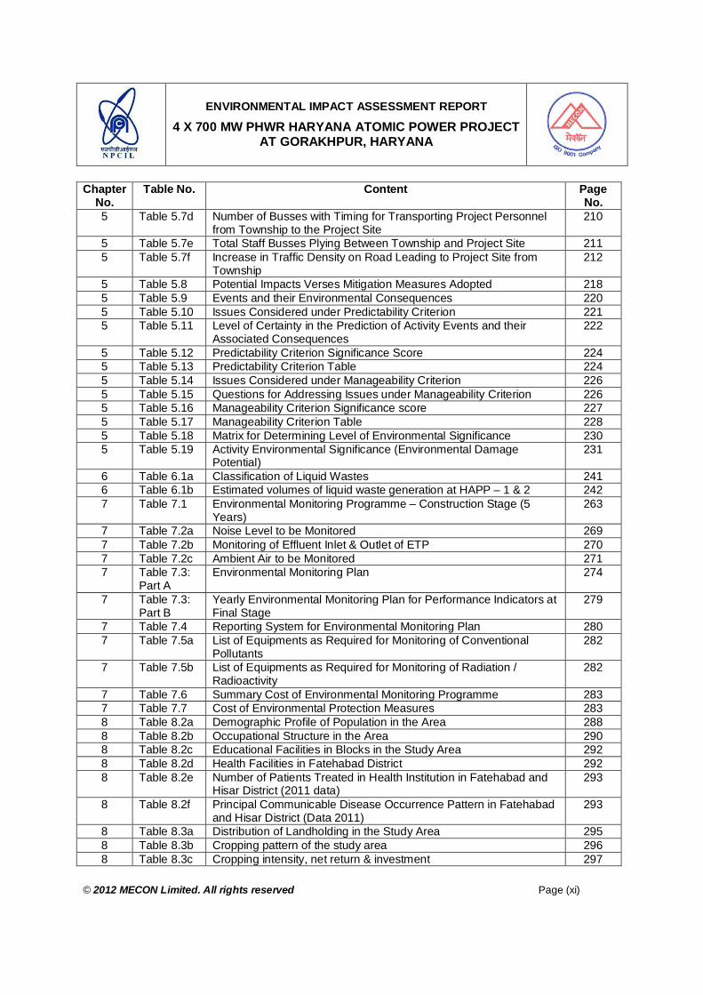
5 Table 5.7d Number of Busses with Timing for Transporting Project Personnel from Township to the Project Site
210
5 Table 5.7e Total Staff Busses Plying Between Township and Project Site 211 5 Table 5.7f Increase in Traffic Density on Road Leading to Project Site from
Township 212
5 Table 5.8 Potential Impacts Verses Mitigation Measures Adopted 218 5 Table 5.9 Events and their Environmental Consequences 220 5 Table 5.10 Issues Considered under Predictability Criterion 221 5 Table 5.11 Level of Certainty in the Prediction of Activity Events and their
Associated Consequences 222
5 Table 5.12 Predictability Criterion Significance Score 224 5 Table 5.13 Predictability Criterion Table 224 5 Table 5.14 Issues Considered under Manageability Criterion 226 5 Table 5.15 Questions for Addressing Issues under Manageability Criterion 226 5 Table 5.16 Manageability Criterion Significance score 227 5 Table 5.17 Manageability Criterion Table 228 5 Table 5.18 Matrix for Determining Level of Environmental Significance 230 5 Table 5.19 Activity Environmental Significance (Environmental Damage
Potential) 231
6 Table 6.1a Classification of Liquid Wastes 241 6 Table 6.1b Estimated volumes of liquid waste generation at HAPP – 1 & 2 242 7 Table 7.1 Environmental Monitoring Programme – Construction Stage (5
Years) 263
7 Table 7.2a Noise Level to be Monitored 269 7 Table 7.2b Monitoring of Effluent Inlet & Outlet of ETP 270 7 Table 7.2c Ambient Air to be Monitored 271 7 Table 7.3:
Part A Environmental Monitoring Plan 274
7 Table 7.3: Part B
Yearly Environmental Monitoring Plan for Performance Indicators at Final Stage
279
7 Table 7.4 Reporting System for Environmental Monitoring Plan 280 7 Table 7.5a List of Equipments as Required for Monitoring of Conventional
Pollutants 282
7 Table 7.5b List of Equipments as Required for Monitoring of Radiation / Radioactivity
282
7 Table 7.6 Summary Cost of Environmental Monitoring Programme 283 7 Table 7.7 Cost of Environmental Protection Measures 283 8 Table 8.2a Demographic Profile of Population in the Area 288 8 Table 8.2b Occupational Structure in the Area 290 8 Table 8.2c Educational Facilities in Blocks in the Study Area 292 8 Table 8.2d Health Facilities in Fatehabad District 292 8 Table 8.2e Number of Patients Treated in Health Institution in Fatehabad and
Hisar District (2011 data) 293
8 Table 8.2f Principal Communicable Disease Occurrence Pattern in Fatehabad and Hisar District (Data 2011)
293
8 Table 8.3a Distribution of Landholding in the Study Area 295 8 Table 8.3b Cropping pattern of the study area 296 8 Table 8.3c Cropping intensity, net return & investment 297

ENVIRONMENTAL IMPACT ASSESSMENT REPORT
4 X 700 MW PHWR HARYANA ATOMIC POWER PROJECT AT GORAKHPUR, HARYANA
© 2012 MECON Limited. All rights reserved Page (xii)
Chapter No.
Table No. Content Page No.
8 Table 8.3d Demand Functions for Food and Non-food Items 298 8 Table 8.3e Source-wise distribution of family consumption 299 8 Table 8.3f Fitted Consumption Function 300 8 Table 8.4 Peoples’ Perception on the Project 302 9 Table 9.1a Threshold Quantity and the Chemicals to be Stored and Handled 313 9 Table 9.1b List of Toxic Chemicals Stored in Very Small Quantity in Laboratory 316 9 Table 9.2 Radiological Emergency and Risk to Public 332 10 Table 10.1 Nuclear and Coal-Fired Power: Per Unit Cost in Paisa Year of 338 10 Table 10.2 Comparative CO2 (GHG) Emissions from Various Energy Sources 339 10 Table 10.3 Qualitative Impacts on Socio-economic Environnent 341 11 Table 11.1 Monitoring / Analytical Equipments Required 349 11 Table 11.2 List of Coordinating Agencies, which may be involved for specific
Environmental Activities 352
13 Table 13.1 List of Sectors for which NABET has given Accreditation 355
LIST OF FIGURES Fig. No. Description Page No.
2.1 Proposed Project Site at Village Gorakhpur, District Fatehabad, Harayana 19 2.2a Reactor Building Elevation – View 1 32 2.2b Reactor Building Elevation – View 2 33 2.3 Secondary Shut Down System 36 2.4 37 Element Fuel Bundle 37 2.5 Simplified Schematic Flow Diagram for 700 MWe PHWR 38 2.6 End Fitting Assembly 39 2.7 Sectional View of Calandria 41 2.8 Diagrammatic Representation of PHT System 46 2.9 Pictorial view of main control room panels for 700 MWe Plant 54 2.10 Scematic Diagram of Liquid Waste Management Scheme 80 2.11 Solid Waste Management Scheme 82
2.12a Longitude and Latitude of the Proposed Project Site 87 2.12b Longitude and Latitude of the Township at Badopal Village 88 2.13 Water Balance Diagram for Haryana Atomic Power Plant 1 & 2. 91
2.14a Views of Township Site (February 2012) 93 2.14b View of Township Site - Prosopis juliflora Growth in Waste Land
(February 2012) 94
2.14c Views of Township Site (February 2012) 95 2.14d Road Leading by the Side of Township Site (February 2012) 96 2.15 Conceptual Pant of the Township 99 2.16 Flow Sheet of Sewage Treatment Plant 105 4.2a Wind-Rose During Summer Season: Day Time 115 4.2b Wind-Rose During Summer Season: Night Time 116 4.2c Wind-Rose During Summer Season: Day & Night (Overall) 117 4.3a SO2 Concentration in the study area 121 4.3b NOx Concentration in the study area 122 4.3c PM10 Concentration in the study area 122 4.3d PM2.5 Concentration in the study area 123 4.3e Ozone concentration in the study area 124
ENVIRONMENTAL IMPACT ASSESSMENT REPORT
4 X 700 MW PHWR HARYANA ATOMIC POWER PROJECT AT GORAKHPUR, HARYANA
© 2012 MECON Limited. All rights reserved Page (xiii)
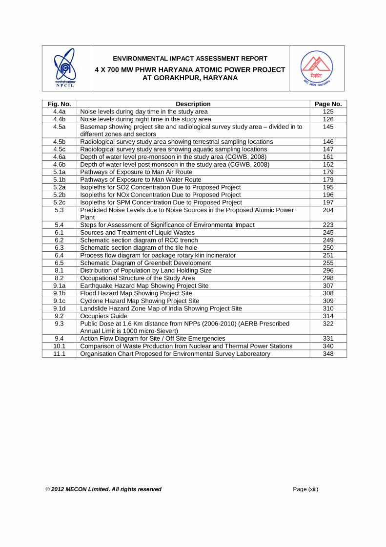
Fig. No. Description Page No. 4.4a Noise levels during day time in the study area 125 4.4b Noise levels during night time in the study area 126 4.5a Basemap showing project site and radiological survey study area – divided in to
different zones and sectors 145
4.5b Radiological survey study area showing terrestrial sampling locations 146 4.5c Radiological survey study area showing aquatic sampling locations 147 4.6a Depth of water level pre-monsoon in the study area (CGWB, 2008) 161 4.6b Depth of water level post-monsoon in the study area (CGWB, 2008) 162 5.1a Pathways of Exposure to Man Air Route 179 5.1b Pathways of Exposure to Man Water Route 179 5.2a Isopleths for SO2 Concentration Due to Proposed Project 195 5.2b Isopleths for NOx Concentration Due to Proposed Project 196 5.2c Isopleths for SPM Concentration Due to Proposed Project 197 5.3 Predicted Noise Levels due to Noise Sources in the Proposed Atomic Power
Plant 204
5.4 Steps for Assessment of Significance of Environmental Impact 223 6.1 Sources and Treatment of Liquid Wastes 245 6.2 Schematic section diagram of RCC trench 249 6.3 Schematic section diagram of the tile hole 250 6.4 Process flow diagram for package rotary klin incinerator 251 6.5 Schematic Diagram of Greenbelt Development 255 8.1 Distribution of Population by Land Holding Size 296 8.2 Occupational Structure of the Study Area 298 9.1a Earthquake Hazard Map Showing Project Site 307 9.1b Flood Hazard Map Showing Project Site 308 9.1c Cyclone Hazard Map Showing Project Site 309 9.1d Landslide Hazard Zone Map of India Showing Project Site 310 9.2 Occupiers Guide 314 9.3 Public Dose at 1.6 Km distance from NPPs (2006-2010) (AERB Prescribed
Annual Limit is 1000 micro-Sievert) 322
9.4 Action Flow Diagram for Site / Off Site Emergencies 331 10.1 Comparison of Waste Production from Nuclear and Thermal Power Stations 340 11.1 Organisation Chart Proposed for Environmental Survey Laboreatory 348

ENVIRONMENTAL IMPACT ASSESSMENT REPORT
4 X 700 MW PHWR HARYANA ATOMIC POWER PROJECT AT GORAKHPUR, HARYANA
© 2012 MECON Limited. All rights reserved Page (xiv)
LIST OF DRAWINGS
SN Description Drawing No. At end of Chapter No.
1 Plant Layout 1 to 4 with Water Storage Ponds and Green Belt Area
HAPP – 1 to 4 / 70000 / 2002 / GA. (DR.LWS) Rev. 01
2
2 Locator Map of 10km Radius Showing Monitoring Stations
Drg. No. MEC/11/S2/Q6SY/01 4
3 Physigraphy in the Study Area Drg. No. MEC/11/S2/Q6SY/02 4 4 Land-Use in the Study Area Drg. No. MEC/11/S2/Q6SY/03 4
CONTENTS OF VOLUME II SN Description (List Of Annexures) Annexure 1 In-principal Approval for Harayana Site form Central Government ANNEXURE IA 2 Haryana R & R Policy2010 ANNEXURE IB 3 MoEF Approved TOR for Haryana Atomic Power Project. ANNEXURE IC 4 Part of presentation to MoEF for approval of TOR ANNEXURE ID 3 Executive Summary of Flood Analysis Report & Safe Grade Elevation of the
Site ANNEXURE II
4 Commitment of Bhakhra Canal Water Availability from Haryana Irrigation Department Authorities
ANNEXURE III
5 Detailed Meteorological Data at Gorakhpur ANNEXURE IVA 6 Detailed Ambient Air Quality Data in Study Area ANNEXURE IVB 6 Authentication of flora and fauna from State Forest Department. ANNEXURE IVC 7 Authentication of Wild Life that no National Park or Wildlife Sanctuary exists
within the Study Area ANNEXURE IVD
8 Provisional Public Dose calculation for Twin –unit 700 Mwe PHWR Station at Gorkhpur, Haryana, HPD, BARC
ANNEXURE V
9 Proceedings of Public Hearing and Commitments - English ANNEXURE VI 10 Proceedings of Public Hearing and Commitments - Hindi ANNEXURE VII
ENVIRONMENTAL IMPACT ASSESSMENT REPORT
4 X 700 MW PHWR HARYANA ATOMIC POWER PROJECT AT GORAKHPUR, HARYANA
© 2012 MECON Limited. All rights reserved Page (xv)
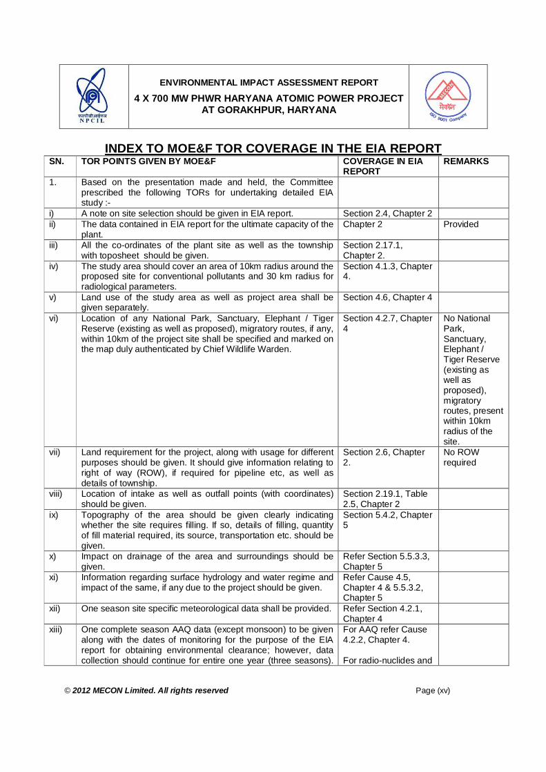
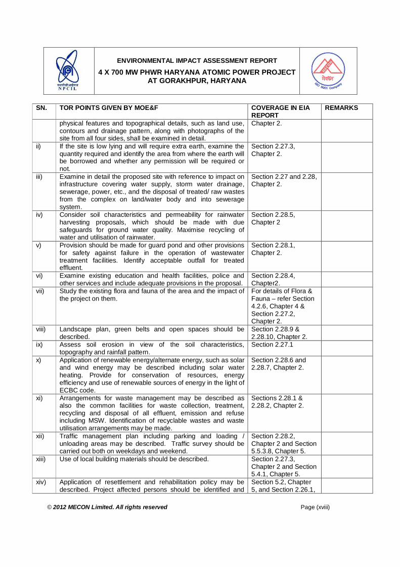
INDEX TO MOE&F TOR COVERAGE IN THE EIA REPORT SN. TOR POINTS GIVEN BY MOE&F COVERAGE IN EIA
REPORT REMARKS
1. Based on the presentation made and held, the Committee prescribed the following TORs for undertaking detailed EIA study :-
i) A note on site selection should be given in EIA report. Section 2.4, Chapter 2 ii) The data contained in EIA report for the ultimate capacity of the
plant. Chapter 2 Provided
iii) All the co-ordinates of the plant site as well as the township with toposheet should be given.
Section 2.17.1, Chapter 2.
iv) The study area should cover an area of 10km radius around the proposed site for conventional pollutants and 30 km radius for radiological parameters.
Section 4.1.3, Chapter 4.
v) Land use of the study area as well as project area shall be given separately.
Section 4.6, Chapter 4
vi) Location of any National Park, Sanctuary, Elephant / Tiger Reserve (existing as well as proposed), migratory routes, if any, within 10km of the project site shall be specified and marked on the map duly authenticated by Chief Wildlife Warden.
Section 4.2.7, Chapter 4
No National Park, Sanctuary, Elephant / Tiger Reserve (existing as well as proposed), migratory routes, present within 10km radius of the site.
vii) Land requirement for the project, along with usage for different purposes should be given. It should give information relating to right of way (ROW), if required for pipeline etc, as well as details of township.
Section 2.6, Chapter 2.
No ROW required
viii) Location of intake as well as outfall points (with coordinates) should be given.
Section 2.19.1, Table 2.5, Chapter 2
ix) Topography of the area should be given clearly indicating whether the site requires filling. If so, details of filling, quantity of fill material required, its source, transportation etc. should be given.
Section 5.4.2, Chapter 5
x) Impact on drainage of the area and surroundings should be given.
Refer Section 5.5.3.3, Chapter 5
xi) Information regarding surface hydrology and water regime and impact of the same, if any due to the project should be given.
Refer Cause 4.5, Chapter 4 & 5.5.3.2, Chapter 5
xii) One season site specific meteorological data shall be provided. Refer Section 4.2.1, Chapter 4
xiii) One complete season AAQ data (except monsoon) to be given along with the dates of monitoring for the purpose of the EIA report for obtaining environmental clearance; however, data collection should continue for entire one year (three seasons).
For AAQ refer Cause 4.2.2, Chapter 4. For radio-nuclides and

ENVIRONMENTAL IMPACT ASSESSMENT REPORT
4 X 700 MW PHWR HARYANA ATOMIC POWER PROJECT AT GORAKHPUR, HARYANA
© 2012 MECON Limited. All rights reserved Page (xvi)
SN. TOR POINTS GIVEN BY MOE&F COVERAGE IN EIA REPORT
REMARKS
The parameters to be covered shall include PM2.5, PM10, SO2 and NOx. Besides, conventional pollutants information on long lived radio nuclides and background natural radio activity, gross alpha and gross beta levels should also be given. The location of the monitoring stations should be so decided so as to take in to consideration the pre-dominant wind direction, population zone and sensitive receptors including reserved forests. There should be at least one monitoring station in the predominant down wind direction at a location where maximum ground level concentration is likely to occur. Baseline data on noise levels may also be generated.
background natural radio activity, Section 4.3, Chapter 4. For baseline noise levels refer Section 4.2.3., Chapter 4.
xiv) Impact of the project on the AAQ of the area. Details of the model used and the input data used for modelling should also be provided. The air project site, habitation nearby, sensitive receptors, if any. The wind roses should also be shown on this map. Levels due to radioactive releases should be predicted and radiation dose there from at the fence post should also be worked out.
For predicted AAQ refer Section 5.5.3, Chapter 5. Predicted radiological releases Section 5.5.2 Chapter 5.
xv) Source of water and its availability. Commitment regarding availability of requisite quantity of water from the competent authority. The availability of water during canal closure should also be detailed and discussed in the report. It may clearly be stated whether any groundwater is to be used in the project or township. If so, detailed hydro-geological study should be carried out.
Refer Cause 2.19, Chapter 2
Ground Water will not be used for the project.
xvi) Details of rainwater harvesting and how it will be used in the plant.
Section 2.28.5, Chapter 2
In the plant area rain water harvesting will not be done to avoid ground water contamination
xvii) Optimization of COC should be done for water conservation. Other water conservation measures proposed in the project should also be given. Quality of water requirement of the project should be optimized.
Section 2.19.3, Chapter 2
xviii) Details of water balance taking into account reuse and re-circulation of effluents.
Section 2.19.2, Chapter 2
xix) Details of greenbelt i.e. land with not less than 1500 trees per ha giving details of species, width of plantation, planning schedule etc.
Section 6.4, Chapter 6
xx) Detailed R&R plan/compensation package in consonance with the National / State R&R Policy for the project affected people including that due to fuel transportation system/pipeline and their ROW, if any, shall be prepared taking into account the socio economic status of the area, homestead oustees, land oustees, landless laborers.
Section 5.2, Chapter 5 No ROW required
xxi) Details of flora and fauna duly authenticated should be provided. In case of any scheduled fauna, conservation plan
Section 4.2.6, Chapter 4.

ENVIRONMENTAL IMPACT ASSESSMENT REPORT
4 X 700 MW PHWR HARYANA ATOMIC POWER PROJECT AT GORAKHPUR, HARYANA
© 2012 MECON Limited. All rights reserved Page (xvii)
SN. TOR POINTS GIVEN BY MOE&F COVERAGE IN EIA REPORT
REMARKS
should be provided. xxii) Details regarding waste management, liquid and solid waste
(conventional and radioactive) should be given in the EIA report.
Refer Section 5.3 & 5.3.4, Chapter 5, page 2 & 21.
xxiii) Details regarding storage and management of spent fuel should be given.
Refer Section 6.3.3.4, Chapter 6
xxiv) Details regarding storage of hazardous chemical including maximum inventory to be stored at any point of time should be given.
Section 9.4.1, Chapter 9.
xxv) Detailed risk assessment and disaster management plan should be given. The risk contours may be plotted on location map.
Refer Chapter 9
xxvi) Issues relating to de-commissioning of the plant and the related environmental issues should be discussed.
Section 5.8, Chapter 5,
xxvii) Demographic data of the study area as well as pre-project health survey of the population in study area around the project site should be collected.
Section 8.2.4, Chapter 8.
xxviii) Detailed environmental management plan to mitigate the adverse environmental impacts due to the project should be given. It should also include possibility of use of solar energy for the project including measures for energy conservation.
Chapter 6, 7 & 11 For Solar energy – refer Sections 2.28.6 & 2.28.7, Chapter 2.
xxix) Details of post project monitoring should also include in the EIA report.
Refer Chapter 7 & 11.
xxx) Details regarding infrastructure facilities such as sanitation, fuel, restroom, medical facilities, safety during construction phase etc. to be provided to the labour force during construction as well as to the casual workers including truck drivers during operation phase.
Section 5.4.1, Chapter 5. Section 5.5.6, Chapter 5.
xxxi) Public hearing points raised and commitment of the project proponent on the same. An action plan to address the issues raised during public hearing and the necessary allocation of funds for the same should be provided.
To be addressed after public hearing
xxxii) Measures of socio economic influence to the local community proposed to be provided by project proponent. As far as possible, quantitative dimension to be given.
Section 8.2.8, Chapter 8.
xxxiii) Impact of the project on local infrastructure of the area such as road network and whether any additional infrastructure would need to be constructed and the agency responsible for the same with time frame particularly keeping in view the transportation of over sized consignments should be given.
Sections 5.5.3.8 & 5.5.3.9, Chapter 5
xxxiv) EMP to mitigate the adverse impacts due to the project along with item wise cost of its implementation.
Refer Chapter 7
xxxv) Any litigation pending against the project and /or any direction /order passed by any Court of Law against the project, if so, details thereof.
Nil
2. In respect of the township, the following TORs are prescribed for addressing the same in the EIA report.
i) A site plan showing the project site and its surroundings with Section 2.24.1,
ENVIRONMENTAL IMPACT ASSESSMENT REPORT
4 X 700 MW PHWR HARYANA ATOMIC POWER PROJECT AT GORAKHPUR, HARYANA
© 2012 MECON Limited. All rights reserved Page (xviii)
SN. TOR POINTS GIVEN BY MOE&F COVERAGE IN EIA REPORT
REMARKS
physical features and topographical details, such as land use, contours and drainage pattern, along with photographs of the site from all four sides, shall be examined in detail.
Chapter 2.
ii) If the site is low lying and will require extra earth, examine the quantity required and identify the area from where the earth will be borrowed and whether any permission will be required or not.
Section 2.27.3, Chapter 2.
iii) Examine in detail the proposed site with reference to impact on infrastructure covering water supply, storm water drainage, sewerage, power, etc., and the disposal of treated/ raw wastes from the complex on land/water body and into sewerage system.
Section 2.27 and 2.28, Chapter 2.
iv) Consider soil characteristics and permeability for rainwater harvesting proposals, which should be made with due safeguards for ground water quality. Maximise recycling of water and utilisation of rainwater.
Section 2.28.5, Chapter 2
v) Provision should be made for guard pond and other provisions for safety against failure in the operation of wastewater treatment facilities. Identify acceptable outfall for treated effluent.
Section 2.28.1, Chapter 2.
vi) Examine existing education and health facilities, police and other services and include adequate provisions in the proposal.
Section 2.28.4, Chapter2.
vii) Study the existing flora and fauna of the area and the impact of the project on them.
For details of Flora & Fauna – refer Section 4.2.6, Chapter 4 & Section 2.27.2, Chapter 2.
viii) Landscape plan, green belts and open spaces should be described.
Section 2.28.9 & 2.28.10, Chapter 2.
ix) Assess soil erosion in view of the soil characteristics, topography and rainfall pattern.
Section 2.27.1
x) Application of renewable energy/alternate energy, such as solar and wind energy may be described including solar water heating. Provide for conservation of resources, energy efficiency and use of renewable sources of energy in the light of ECBC code.
Section 2.28.6 and 2.28.7, Chapter 2.
xi) Arrangements for waste management may be described as also the common facilities for waste collection, treatment, recycling and disposal of all effluent, emission and refuse including MSW. Identification of recyclable wastes and waste utilisation arrangements may be made.
Sections 2.28.1 & 2.28.2, Chapter 2.
xii) Traffic management plan including parking and loading / unloading areas may be described. Traffic survey should be carried out both on weekdays and weekend.
Section 2.28.2, Chapter 2 and Section 5.5.3.8, Chapter 5.
xiii) Use of local building materials should be described. Section 2.27.3, Chapter 2 and Section 5.4.1, Chapter 5.
xiv) Application of resettlement and rehabilitation policy may be described. Project affected persons should be identified and
Section 5.2, Chapter 5, and Section 2.26.1,

ENVIRONMENTAL IMPACT ASSESSMENT REPORT
4 X 700 MW PHWR HARYANA ATOMIC POWER PROJECT AT GORAKHPUR, HARYANA
© 2012 MECON Limited. All rights reserved Page (xix)
SN. TOR POINTS GIVEN BY MOE&F COVERAGE IN EIA REPORT
REMARKS
rehabilitation and resettlement plan should be prepared. Chapter 2. xv) Examine separately the details for construction and operation
phases both for Environmental Management Plan and Environmental Monitoring Plan.
Refer Chapter 6, 7 & 11
xvi) Examine and prepare in detail the Disaster Management Plan and emergency Evacuation Plan for natural and manmade disasters like earthquakes, cyclones/flooding, Tsunami and terrorists attack.
Section 2.28.11 and Chapter 9
3. Besides the above, the below mentioned points will also be followed:-
a) All the information contained in various project documents should be rechecked and reconciled.
Followed in the report
b) All documents to be properly referenced with index, page numbers and continuous page numbering.
Followed in the report
c) Where data are presented in the report especially in tables, the period in which the data were collected and the sources should be indicated.
Followed in the report

ENVIRONMENTAL IMPACT ASSESSMENT REPORT
4 X 700 MW PHWR HARYANA ATOMIC POWER PROJECT AT GORAKHPUR, HARYANA
© 2012 MECON Limited. All rights reserved Page (xx)
ABBREVIATIONS
AAQM : Ambient Air Quality Monitoring AERB : Atomic Energy Regulatory Board AFR : Away From Reactor AOO : Anticipated Operational Occurrence AP : Activation Products AVS : Annulus Ventilation System BA : Basal Area BARC : Bhabha Atomic Research Centre BDBAs : Beyond Design Basis Accidents BDL : Below Detectable Level BHAVINI : Bhartiya Nabhikiya Vidyut Nigam BOD : Biochemical Oxygen Demand COD : Chemical Oxygen Demand CCWS : Component Cooling Water System CDF : Core Damage Frequency CEC : Cation Exchange Capacity CFU : Colony Forming Unit CHC : Community Health Center CPCB : Central Pollution Control Board CVCS : Chemical and Volume Control System D : Density D.O. : Dissolved Oxygen DAE : Department of Atomic Energy DBAs : Design Basis Accidents DBF : Design Basis Flood DNB : Departure from Nucleate Boiling DS : Down Stream EBS : Extra Borating System EDG : Emergency Diesel Generator EFWS : Emergency Feed Water System EIA : Environmental Impact Assessment Study EMP : Environmental Management Plan/ Environmental Monitoring Plan ESL : Environmental Survey Laboratory ESP : Exchangeable Sodium Percentage F : Frequency FA : Fuel Assemblies FBRs : Fast Breeder Reactor FP : Fission Products FPCS : Fuel Pool Cooling System FPNGs : Fission Product Noble Gases GSI : Geological Survey of India GWPS : Gaseous Waste Processing System HEPA : High Efficiency Particulate Air HP : High pressure HPD : Health Physics Division I&C : Instrumentation and Control IAEA : International Atomic Energy Agency

ENVIRONMENTAL IMPACT ASSESSMENT REPORT
4 X 700 MW PHWR HARYANA ATOMIC POWER PROJECT AT GORAKHPUR, HARYANA
© 2012 MECON Limited. All rights reserved Page (xxi)
ICRP : International Commission on Radiation Protection IIG : Indian Institute of Geomagnetism IMR : Infant Mortality Rate IRWST : In- containment Refueling Water Storage Tank IUCN : International Union for Conservation Of Nature And Natural Resources IVI : Importance Value Index KAPP : Kakrapar Atomic Power Project KKNPP : Kudankulam Nuclear Power Project LBLOCA : Large Break Loss Of Coolant Accident LCO : Limiting Conditions for Operation LHSI : Low Head Safety Injection LOCA : Loss Of Coolant Accident LP : Low Pressure LRF : Large Release Frequency MDR : Major District Road MF : Membrane Filter MFW : Main Feed Water MHSI : Medium Head Safety Injection MoEF : Ministry of Environment & Forests MOU : Memorandum of Understanding MSS : Main Steam System NAPP : Narora Atomic Power Project NOx : Oxides of Nitrogen NPCIL : Nuclear Power Corporation of India Ltd ODC : Over Dimensional Consignment OSHA : Occupational Safety and Health Administration PAPs : Project Affected Persons PFBR : Prototype Fast Breeder Reactor PGA : Peak Ground Acceleration PHC : Primary Health Centre PPED : Power Projects Engineering Division PHWRs : Pressurised Heavy Water Reactors PSAR : Preliminary Safety Analysis Report PWD : Public Work Department PWRs : Pressurised Water Reactor PZR : Pressurizer R&R : Rehabilitation And Resettlement RCC : Reinforced Cement Concrete /Risk Reduction Category RAPS : Rawatbhata Atomic Power Station RBA : Relative Basal Area RCP : Reactor Coolant Pump RD : Relative Density RHR : Residual Heat Removal RPM : Respirable Particulate Matter RPV : Reactor Pressure Vessel RSPM : Respirable Suspended Particulate Matter RSS : Remote Shutdown Station SAHRS : Severe Accident Heat Removal System SDI : Simpson Diversity Index

ENVIRONMENTAL IMPACT ASSESSMENT REPORT
4 X 700 MW PHWR HARYANA ATOMIC POWER PROJECT AT GORAKHPUR, HARYANA
© 2012 MECON Limited. All rights reserved Page (xxii)
SG : Steam Generator SO2 : Sulphur dioxide SPM : Suspended Particulate Matter SRW : Solid Radioactive Waste SSE : Safe Shutdown Earth Quake SSS : Start-up and Shutdown System TAPS : Tarapur Atomic Power Station TDS : Total Dissolved Solids TSS : Total Suspended Solids US : Up Stream

Executive Summary
4 X 700 MW PHWR HARYANA ATOMIC POWER PROJECT AT GORAKHPUR HARYANA
© 2012 MECON Limited. All rights reserved Page ES-1 of ES-14
Executive Summary
EXECUTIVE SUMMARY 1.0 INTRODUCTION
Nuclear Power Corporation of India Limited (NPCIL) is a Public Sector Enterprise under Department of Atomic Energy (DAE), Government of India. NPCIL’s objective is to develop nuclear power technology and to undertake generation of electricity under the provisions of Atomic Energy Act, 1962. NPCIL’s emphasis is to produce Nuclear Power as a safe, environmentally benign and economically viable source of electrical energy to meet the increasing needs of the country.
In pursuance of Environmental (Protection) Act, 1986 and EIA notification 2006, new projects necessitate statutory prior environmental clearance by conducting an Environmental Impact Assessment (EIA) study. NPCIL entrusted MECON Limited to conduct an EIA study for the proposed project.
2.0 PROJECT DESCRIPTION
2.01 Nature and Size of the Project
The Haryana Atomic Power Project (HAPP) will produce 4X700 MWe power. It falls under category of "Nuclear Power Project & Processing of Nuclear Fuel".
2.02 Location The project site is located in Gorakhpur Village, Bhuna Block, Tehsil, Sub-division & District Fatehabad, Haryana, at geographical co-ordinates of longitude 750 37’ 56” E and latitude 290 26’ 30” N. and situated about 215 to 218m above mean sea level (MSL). The site is about 28 km in SE direction of Fatehabad town (district head-quarter) and is about 6.0 km from NH10 (connecting Hisar to Fatehabad). The nearest railway station is Uklana Mandi (23 km) on Northern railway. Hisar is situated about 33 km on the SSE of the project site. The nearest Airports to the plant site is at Hisar (used for Helicopter training) at a distance of about 40 km from the plant site and Indira Gandhi International Airport, Delhi is about 208 km from project site. The Bhakhara Canal (Fatehabad Branch) flows from east to west towards north close to the site. There is no major industry and no place of historical importance within 10 km off the site. There are no facilities for handling, storing or transporting inflammable/toxic material and no major railway siding or road transport depot within 10 km of the site. The site connects NH10 by Kharakheri-Gorakhpur road. The Index map showing the location of the plant site is shown in Fig. 1.
The total 1503.5 acres (608.48 ha) land required is private land, of which that required for the project is about 1318 acres (533.5 hectares) and that for township is about 185.42 acres (75.04 hectares). The project site land (534 ha) comprises 1273.2 acres or 515.24 ha of land under agricultural category and 32 ha of land is not cultivable. The land at the township comprises mostly barren land. The locations of proposed site at Gorakgpur is shown in Fig. 1.
2.03 The Proposed Project The Nuclear Power Corporation of India Ltd (NPCIL) is intended to setup Haryana Atomic Power Project (HAPP) 4x700 MWe Pressurized Heavy Water Reactor (PHWR) units at Gorkhapur, Dist Fatehabd. The major equipments needed are Steam Generators, End-

Executive Summary
4 X 700 MW PHWR HARYANA ATOMIC POWER PROJECT AT GORAKHPUR HARYANA
© 2012 MECON Limited. All rights reserved Page ES-2 of ES-14
Executive Summary
Shield, Calandria, Coolant Channels, End Fittings, Primary Coolant pumps, Heat Exchangers, Fuelling Machine components, etc.
Fig.1: Proposed Project Site at Village Gorakhpur, District Fatehabad, Haryana
The above equipments will be housed in Nuclear buildings consisting of:
Reactor Building (RB) and Reactor Auxiliary Building (RAB) house the main reactor and associated process systems,
Safety related Buildings other than Nuclear Building consisting of Control Building (CB), Station Auxiliary Building (SABs), Ventilation Stack with Monitoring Room and Station Auxiliary Buildings (SABs), D2O Upgrading Plant Building, Waste Management Facility and Exhaust Ventilation, Induced Draught Cooling Towers, Safety Related Pump House (SRPH), Fire Water Pump House, Underground Tunnels and Trenches, Diesel Oil Storage Area (DOSA), Emergency Makeup Water Pond, Covered Passage, etc as per the design features of the plant.
Power Evacuation “in principal” is feasible for 2800 MWe power from site. The Power generated at HAPP will be evacuated through 400 kv transmission system. The number of
Proposed Site
NH
NH Other Roads Canals
Proposed Site
NH
NH Other Roads Canals

Executive Summary
4 X 700 MW PHWR HARYANA ATOMIC POWER PROJECT AT GORAKHPUR HARYANA
© 2012 MECON Limited. All rights reserved Page ES-3 of ES-14
Executive Summary
transmission outlets and their destination will be finalized taking into account share of beneficial state in due course after a detailed power system studies are carried out by Power Grid Corporation of India Limited (PGCIL) and approved by the concerned authorities “
The project will use Natural uranium oxide as fuel and heavy water (D2O) as coolant and moderator for the reactor with on-power refueling of reactor.
Steam generators supply nearly dry saturated steam to the turbine and turbine is directly coupled to an electrical generator, which produces electricity. Generator voltage is stepped up by the generator transformer. Generated power is transmitted to the grid from the nuclear power station at 400 kV.
The concept of defense-in-depth is adopted in design of safety systems. Provision of multiple barriers, double containment structures with liner on inner containment wall of Reactor Building, containment spray cooling system, emergency core cooling system, reactor shut down systems etc. as engineered safety systems ensure safe operation of reactor. Reactor protection system ensures shutdown requirements through two independent fast acting shut down systems. Reactor regulating system enables automatic control of reactor power and maintains neutron flux profile.
Construction of the project will be taken up in two stages of 2X700 MWe each. Subsequent two units are expected to be four years later. The 1st stage project will be commissioned in 60 months from the “Zero-Date” as August 2013 i.e. the start of construction activities at site.
During construction stage maximum of 8000 persons (when construction of stage-I will be nearing completion and construction of stage-II will be started) will be temporarily deployed and up to the final stage of the project about 1700 manpower will be required (covering technical and general administration).
During construction & commissioning maximum 10 MW power will be required which will be sourced from State Grid. The water requirement for the project will be met from Fatehabad Branch of Bhakra Canal. Assurance has been given to supply 783 Million Liters per Day (MLD) or 32625 m3/hr and that for the township about 0.65 MLD or 27 m3/hr of water from Haryana Government. About 18000m3/hr of water will be required for unit 1 to 4 for cooling tower makeup and other plant requirements. Out of which 12680 m3/hr will be towards consumptive use and the rest of the 5320 m3/hr will be returned to canal.
Township A residential colony for about 1700 employees has been envisaged, with main features as follows: a. Land area is : 75 Ha b. Ground Coverage area : 28.4 Ha (37.8%) c. Built up area = 26.00 Ha [Floor Space Index (FSI1) : 0.34]. d. The township will have a maximum height of Ground + two stories limited to maximum
height of 11.45 m. e. Water Consumption = 1.250 Million Litres Per Day (MLD) or 1250 m3/d f. Power requirement = 2000 KVA for stage one and 2000 KVA for stage two. A 500 KVA
Standby DG set will be provided. g. Connectivity: Via local roads near Badopal village on National High way number (NH-10)
connecting Hisar and Fatehabad. 1 Floor Space Index (FSI) = Total floor area including walls of all floors / Plot Area / Building Unit

Executive Summary
4 X 700 MW PHWR HARYANA ATOMIC POWER PROJECT AT GORAKHPUR HARYANA
© 2012 MECON Limited. All rights reserved Page ES-4 of ES-14
Executive Summary
h. Parking requirements: Adequate parking space of about 1500 cars, light commercial vehicles, buses etc. - available in the township.
i. Community facilities: Hospital, Community centre, School and shopping centre recreation club, sports complex, play ground, bank, post office, petrol pump etc. will be provided in the proposed township.
j. All the civic amenities. k. Measures to minimize energy consumption
Use of CFL2 Use of Low-pressure sodium lamps for outdoor lighting along the road and security
lighting with Solar Street Lights mix. Use of solar water heater for hospital, guest house. Automatic timing control mechanism will be incorporated in the street lighting to save
energy. Mechanism will involve staggering of on-off sequence of street lights. l. Sewage treatment plant of 1MLD envisaged for treatment of sewage water. The treated
sewage shall be disinfected / filtered and used for gardening purpose. m. Green belt will be developed in and around the township. n. A fire extinguishing system as per the requirements of national Building Code will be
provided.
The estimated cost of 4 X 700MWe PHWR Atomic Power Project is about Rs 23502 Crores (base cost 2011-12).
3.0 DESCRIPTION OF THE ENVIRONMENT
3.01 General Study area has been taken as 10km radius around the project site for conventional pollutant and other baseline study for which the baseline environmental data monitoring was conducted during March 2011 to May 2011 (summer season). Whereas for baseline radiological monitoring the study area taken was 30km radius around the project site and the study was conducted during January to March 2011.
3.02 Meteorology In summer season overall, the predominant wind directions for March 2011 – May 2011 were NW, W, NE, SE, SW, and N (prevailing for 16.03%, 10.06, 6.33, 4.75 and 4.34 of the time). Calm conditions prevailed for 29.39% of the time. The wind velocity was mostly between 1.6 to 18.0 km/hr (70.59% of the time).
3.03 Ambient Air Quality (AAQ) Eight AAQ monitoring stations were monitored. The maximum values of Particulate Matter (PM10 & PM2.5), SO2 , NOx and Ozone (O3) at all the monitoring stations the values of different pollutants were below the National AAQ Standards for Industrial, Residential, Rural & Other Areas as well as for ecologically sensitive areas (Table ES.2).
Table ES 2: Summarised Results of AAQ Monitoring Parameters Gorakhpur
A1 Nehla
A2 Siwani
A3 Kirmara
A4 Chaubara
A5 Sabarwas
A6 Kajalheri
A7 Khaujri
A8 Max 15 14 20 18 12 13 14 11 Min. 5 4 4 4 5 4 5 5 Avg 9 7 10 9 8 8 9 7
SO2 (µg/m3)
C 98 15 12 19 17 12 13 14 11 2 Compact fluorescent lamp (CFL) or Compact Fluorescent Light

Executive Summary
4 X 700 MW PHWR HARYANA ATOMIC POWER PROJECT AT GORAKHPUR HARYANA
© 2012 MECON Limited. All rights reserved Page ES-5 of ES-14
Executive Summary
Parameters Gorakhpur A1
Nehla A2
Siwani A3
Kirmara A4
Chaubara A5
Sabarwas A6
Kajalheri A7
Khaujri A8
Max 31 23 36 46 19 30 24 17 Min. 9 7 8 6 8 5 8 8 Avg 17 13 21 17 13 14 14 13
NOx (µg/m3)
C 98 29 20 36 40 19 27 23 17 Max 85 84 84 86 72 87 83 65 Min. 53 52 49 42 52 59 50 45 Avg 78 72 72 74 63 76 64 59
PM10 (µg/m3)
C 98 85 84 84 86 72 87 80 65 Max 49 49 46 48 46 49 48 44 Min. 22 29 28 25 29 29 29 30 Avg 37 41 39 41 35 43 38 38
PM2.5 (µg/m3)
C 98 48 49 46 47 44 49 47 44 Max 35 33 34 33 36 34 34 34 Min. 22 21 20 21 20 21 20 21 Avg 28 26 26 26 27 26 25 26
O3 (µg/m3)
C 98 35 33 33 33 36 34 33 33
3.04 Ambient Noise Noise mmonitoring was conducted at ten locations in and around the project site. The values at all stations were below the respective statutory norms as applicable.
3.05 Water Environment Four surface and four ground water samples were analysed for the study. All the parameters in surface waters were within the CPCB norms for Classes B, C, D, and E for surface water. Ground water analysis reveals that in village Sabarwas (GW2), total hardness, Chloride, TDS, Ca, Mg and Alkalinity is exceeding the respective desirable / permissible norms of IS:10500. Whereas in village Samani (GW3) TDS is higher than desirable limits. Other parameters of all the samples are within the limits with the drinking water quality standards (IS :10500).
3.06 Soil Soil samples were analysed for ten locations in and around the project site and were found good for plant growth.
3.07 Ecological Features There is no wildlife or bird sanctuary within the study area. The study area falls under agro-climatic zone “Trans-Gangetic Plains Region” and under climatic region arid to semi arid - characterised by dryness and extremes of temperature and scanty rainfall. The vegetation is characterized by “tropical desert thorn” and comprises predominantly of xerophytes.
3.08 Traffic Density The traffic density on NH 10 is highest for LMV (5167/d), followed by HMV (1841/d) and two wheelers (1940/d), whereas that on road leading to project site from NH 10 is highest for two wheelers (452/d), followed by LMV (341/d) and HMV (11/d).
3.09 Hydrogeology Normal annual rainfall of Fatehabad district is 373 mm falling in 22 rainy days. The groundwater is in water table condition at a depth of 3 to 20m below ground level and in semi confined.
3.10 Socio-economic Status

Executive Summary
4 X 700 MW PHWR HARYANA ATOMIC POWER PROJECT AT GORAKHPUR HARYANA
© 2012 MECON Limited. All rights reserved Page ES-6 of ES-14
Executive Summary
The 10 km study area consists of 83044 persons. Basic socio-economic conditions are: The population density up to 5 km is minimum followed by that in 10 km radius. The study area consists of mostly rural population. Predominance of individual land holdings in small to marginal category. Wheat is mostly
grown followed by cotton, paddy, gwar, etc. The employment rate is moderate: 43% are engaged as main workers, 17% as marginal
workers and 40% as non-workers. Agriculture and small commercial activities plays an important role in rural economy.
3.11 Baseline Study for Radiological Environment The 30 km study area for radiological monitoring was divided into four zones 1, 2, 3 and 4 (1.0 - 5 km, 5 - 10 km, 10 - 15 km, and 15 - 30 km, respectively) and further divided in to 16 circle-segments / sectors from A to P, taking the project site as centre.
The Ambient Radiation Levels (Gamma radiation level) was measured using Gamma dose rate tracer. The gamma radiation levels ranged between 0.07-0.22 µGy/h, which is normal and comparable with Kakrapar and Kaiga sites.
The pre-operational Base Line Levels of Natural and Fallout Radio-nuclides were measured in terms of radio-nuclides of natural (238U, 232Th, 40K) and fallout (137Cs and 90Sr) origin by taking environmental samples from terrestrial and aquatic environs. Canal water, soil, cereals, pulses and vegetation samples were collected from the study area.
Air samples Five air samples were analysed for gross alpha and beta activities. The gross beta activity ranged between BDL (<0.007 Bq.m-3) to 0.017 Bq.m-3 and gross alpha ranged from 0.0002 to 0.003 Bq.m-3.
Radioactivity levels in water samples Fifteen (15) water samples were analysed for gross alpha and beta activities. The Gross alpha activity ranged from 6.7 mBq.l-1 to 281.3 mBq.l-1 and the gross beta activity ranged from MDL (<225 mBq.l-1) to 332.6 mBq.l-1. Higher gross alpha activities as compared to other power station sites may be attributable to comparatively higher concentrations of Uranium in ground water.
Radioactivity levels in soil Fourteen samples were analysed for baseline radio-activity level in soil. The 226Ra activity ranged from 9.6 to 70.9 Bq.kg-1dry wt, 238U activity varied from 11.5 to 70.8 Bq.kg-1dry dry wt, the 232Th activity varied from 20.2 to 118.7 Bq.kg-1dry dry wt. The 226Ra and 238U concentrations are found to be higher than those observed in other power station sites of India. 40K concentrations in soil varied from 249.6 to 1353 Bq.kg-1dry wt. The observed values are comparable with those observed in other power station sites. The 137Cs and 90Sr concentrations in soil samples from the study area are comparable to the levels reported elsewhere(3).
Radioactivity levels (137Cs, 90Sr and 40K) in biological samples
3 UNSCEAR 2000, Sources and effects of ionizing radiation, Report to General Assembly, with Scientific Annexes, United Nation, 2000.

Executive Summary
4 X 700 MW PHWR HARYANA ATOMIC POWER PROJECT AT GORAKHPUR HARYANA
© 2012 MECON Limited. All rights reserved Page ES-7 of ES-14
Executive Summary
Radioactivity levels in food and related matrices are monitored in terms of 137Cs and 90Sr in ten (10) biota (biological) samples, covering grass, cereals, leaves, fruits, etc. The activity levels of 137Cs and 90Sr are comparable to the levels reported elsewhere(4).
4.0 ANTICIPATED ENVIRONMENTAL IMPACTS & MITIGATION MEASURES
4.01 Impact and Mitigation : Construction Phase The main Plants units of the project will be establish in 608.5 ha of area which includes exclusion zone of 1 km around the reactor building of the main plant of the project. For land acquisition, R&R policy 2010 of Government of Haryana agreed with local bodies / PAPs will be implemented in phases. Only land Oustees and no homestead population involved. A total of 979 PAP’s due to land acquisition. For acquisition of the private land, R&R policy 2010 of Haryana - shall be followed. No forest land is involved in the project.
4.02 Impacts and Mitigation : Project Design The HAPP is being envisaged based on the state of art technology as presently available in the country. A number of environment friendly / safety features have been envisaged which ensures that the anticipated adverse environmental impacts are either avoided or minimized.
The basic design of the Atomic Power Plant allows for a. Normal Releases of radioactive or chemical pollutants to the environment within
statutory limits. b. There could be accidents, off normal situations with potential for large uncontrolled
releases are minimized with probability of occurrence within statutory limit.
The first approach aims to avert such situations to the best extent possible. This is done by monitoring and rigorously controlling the plant operating conditions.
The second approach aims at designing the facility with multilayer of safety system in such a way that even if the event were to occur, the resulting unplanned releases are contained as far as practical. Provisions are made for directing the releases along planned flow paths, thereby permitting their collection and treatment before discharge to the environment. This is facilitated by handling / processing radioactive material in confined space, the confinement being assured by providing multiple barriers between the environment and the radiation sources. The multiple barrier approach is applied not only in processing, but also in storage of hazardous materials / wastes.
Apart from the steps taken to avert / contain unplanned releases, the design provides for the reduction of pollution burden by minimizing the quantum of wastes generated in normal operation also.
The concept of defense-in-depth is adopted in design of safety systems, various state of the art safety systems mechanisms are engineered to ensure safe operation of the reactor, viz
Barriers to radioactive release: Multiple series of fission product barriers designed to prevent radioactivity release, viz.
i) Fuel matrix ii) Fuel sheath iii) Primary Heat Transport System iv) Containment
4 UNSCEAR 2000, Sources and effects of ionizing radiation, Report to General Assembly, with Scientific Annexes, United Nation, 2000.
Executive Summary
4 X 700 MW PHWR HARYANA ATOMIC POWER PROJECT AT GORAKHPUR HARYANA
© 2012 MECON Limited. All rights reserved Page ES-8 of ES-14
Executive Summary
Special safety zones : The entire operating island is designed to be divided into 3 distinct zones based on the contamination potential. These zones have been designated as Zone-1, Zone-2 and Zone-3 in the ascending order of contamination potential. These zones are equipped with required safety features to limit the potential radiation within limits.
Exclusion zone Double containment structures with liner on inner containment wall of Reactor Building, Containment spray cooling system, Emergency core cooling system, Reactor shut down systems etc. Reactor protection system ensures shutdown requirements through two independent fast
acting shut down systems. Reactor regulating system enables automatic control of reactor power and maintains
neutron flux profile.
4.03 Operational Phase Impact
4.3.1 Radio-active Releases
The uranium dioxide (UO2) is used as fuel. At normal operating conditions all solid fission products are permanently retained in UO2 matrix and only a fraction of noble gases and volatile products diffuse into the inter space between fuel and cladding. Waste management operations (liquid and solid), involves handling of radioactive wastes from all the facilities for their ultimate storage/disposal.
All the processes / operations are carried out in leak tight enclosures, under negative pressure so that the probability of the radioactive materials reaching the working environment is reduced to a minimum. However, a small fraction of these radio-nuclides are released into the environment in the form of gaseous emissions and liquid effluents are released into the environment within statutory limit.
The radiation dose limit specified by AERB for the general pubic at the fence post (exclusion zone) due to operation of all facilities within the site through all pathways is 1 mSv/yr (100 mrem/y). Compliance to this regulatory requirement is ensured by dose apportionment estimation for different types of radio-nuclides of all the facilities. The dose apportionment estimation implicitly specifies discharge limits for each kind of anticipated radionuclide. A conservative estimate of dose apportionment of radioactivity released from HAPP has been done as 0.40 mSv for the twin-unit 700-MWe HAPP.
Radioactive Air Emissions Impacts: The radioactivity through air route will be discharged within AERB limit which will not cause any adverse impact to surrounding life systems.
Mitigation Measures Design of the plant is based on minimizing the leakages from the plant system in to plant
buildings so that generation of radioactive effluents is minimized. Gaseous radioactive effluents from reactor and service building ventilation exhaust
systems are passed through pre filters and absolute filters (to confine any radioactive materials in the exhaust streams) before discharge through the 100m ventilation stack.

Executive Summary
4 X 700 MW PHWR HARYANA ATOMIC POWER PROJECT AT GORAKHPUR HARYANA
© 2012 MECON Limited. All rights reserved Page ES-9 of ES-14
Executive Summary
Gaseous effluents are continuously monitored for radioactivity content before discharging through ventilation stack.
Radioactive Liquid Effluent Discharges Impacts Effluent waste containing radioactivity levels above AERB norms if discharged to
receiving water bodies may cause radiation exposure to canal biota and downstream users of the canal water.
The cooling water if discharged at high temperature may cause concern to the flora and fauna in the receiving water bodies.
Mitigation Measures Design of the plant is based on minimizing the radioactive leakages from the plant system
in to plant buildings to minimized generation of radio-active effluents. Designed radioactive waste management facilities will treat different levels of radioactive
effluents to meet the authorized release limits stipulated by AERB. Total Dilution water to be discharged will be 5320 m3/hr, which will be continuously
monitored for radioactivity levels. . Periodical monitoring of receiving water body water quality at up-gradient and down
gradient of the effluent discharge point.
Radio-active Solid Waste Disposal Radioactive solid waste will be segregated at source depending upon its nature (compactable / non-compactable) and surface dose rate.
Impacts Solid waste generated from different units to the tune of 514m3/yr will not cause radiation dose to the member of public beyond AERB approved Dose limit as it will be segregated, handled and disposed off with the application of advanced technology.
Mitigation Measures Treatment and disposal of radioactive solid waste at the plant is carried out as per AERB
/ SG / D-13. Solid wastes will be transported to Waste Management Plant (WMP) in shielded
containers / casks, for treatment / conditioning (if needed) and then will be disposed off in engineered barriers (trenches, vaults and holes) at the Near Surface Disposal Facility (NSDF).
Packages having higher activity will be disposed off at the bottom of trenches / vaults and will be suitably sealed permanently as per established practices.
The NSDF area will be fenced and necessary access control procedures will be established.
The dose rate on the top of the sealed earth trenches and RCC trenches / vaults will not exceed 0.01 mGy/h.
4.3.2 Conventional Pollutants
Air Environment : Impacts No direct use of fossil fuel in the plant process. However, for each unit of 700MWe there are 4 DG sets (1w + 3 stand by), for use during power failure. Each DG set is of capacity 4.2 MW (sufficient for supplying power to one 700MWe reactor unit) with fuel (HSD) consumption of 979kg/hr. Thus 4 DG set will run for 24 hours during emergency power failure situation.

Executive Summary
4 X 700 MW PHWR HARYANA ATOMIC POWER PROJECT AT GORAKHPUR HARYANA
© 2012 MECON Limited. All rights reserved Page ES-10 of ES-14
Executive Summary
The resultant ambient air concentrations if the DG sets are run for 24 hrs continuously has been presented in Table 3 for PM, SO2 & NOx. The values of different parameters are well within the National Ambient Air Quality norms. Thus there will not be any adverse changes in AAQ in the study area due to the project.
Table 3: Expected Ambient Air Quality after Proposed Plant
Pollutants Monitored (Max. C98)
(µg/m3)
Anticipated Maximum contribution of pollutants in µg/m3 due to proposed plant (maximum GLC occurrence co-ordinate)
AAQ after proposed plant
(µg/m3) Four DG sets of 4.2 MW capacity each during emergency running continuously for 24 hrs
RPM 87.0 1.5 (18, 2.5km) 88.5 SO2 19.0 1.29 (17, 2.5km) 20.3 NOx 40.0 1.3 (17, 2.5km) 41.3
*Concentrations are in µg/m3 and of 24 hours averaging time. Values in the parenthesis indicate the coordinates of the grid points in Km (10, 10 km) is the centre of the plant.
.
Mitigation Measures During the design phase all efforts have been made to adopt latest state of art technology and to install adequate pollution control measures for point and fugitive emission sources so as to meet the MOE&F / CPCB air emission norms. The following mitigation measures will be employed to reduce the pollution level to acceptable limits: Stack monitoring to ensure proper functioning of pollution control systems. Air monitoring in the Work-zone. Adequate plantation in and around different units and around the plant. Monitoring of ambient air quality (AAQ).
4.3.3 Water Environment: Impacts The plant water requirement will be 4.5 m3/hr per MWe, with cycle of concentration (COC) as 3, to be met from Fatehabad Branch of Bhakra Canal. Necessary permission has been accorded from Government of Haryana. About 18000m3/hr water will be required for unit 1 to 4, out of which 12680 m3/hr will be towards consumptive use and the rest of the 5320 m3/hr will be returned to canal. Total sewage generated from township will be about 34 m3/hr and from plant will be 3.5m3/hr. No impact on ground water is envisaged as ground water will not be drawn. Plant operation does not have any impact on drainage pattern and expected to remain as it is.
Mitigation Measures Effluent quality monitoring at inlet and outlets of STP in plant and in township. The STP
treated water will be used for green belt development in the respective areas and only the excess will be discharged.
In addition, rain water harvesting and monitoring of ground water levels in and around the area of the proposed project will be done.
4.3.4 Solid Waste Disposal: Impacts and Mitigation Measures The Hazardous wastes like active Organic Liquid waste like Oil, lubricants, scintillation liquid etc are burnt along with low radioactive level solid waste in incinerator, with burning capacity 20 kg/hr consuming 50 liter/hr furnace oil. The incinerator will be operated for 2 to 3 days per month. The flue gas will passed through two stage water scrubber. The ash and scrubbing water after solidification / embedment in cement will disposed in RCC trenches. Continuous monitoring system is provided to monitor the gas emitted from the chimney. The Lead Acid Battery generated will be sold to registered recyclers.

Executive Summary
4 X 700 MW PHWR HARYANA ATOMIC POWER PROJECT AT GORAKHPUR HARYANA
© 2012 MECON Limited. All rights reserved Page ES-11 of ES-14
Executive Summary
4.3.5 Noise Levels: Impacts Considering the attenuation due to specially designed building within which noise generating machineries will be housed, the increase in noise levels will be around 1-2 dB(A) just outside the building. Thus, there will not be any change in the ambient noise levels due to operation of nuclear power plant. Noise in the work place generated from operation of equipment is the only concern.
Mitigation Measures: All the equipment in different units designed/operated that the noise level will not exceed
85 dB (A) at a distance of 1m. The noise generating equipments are housed in acoustic enclosures / buildings. The
presence of exclusion zone (1 km) with greenbelt will serve to insulate generated noise. Periodical monitoring of work zone noise and outside plant premises. Workers exposed to noise level will be provided with protection devices like earmuffs and
will be deployed with rotational duties. All workers will be regularly checked medically for any noise related health problem and
if detected, they will be provided with alternative duty.
4.3.6 Impact of Transportation During construction stage there will be only marginal increase in traffic load on the road leading to the project site, thus no impact is anticipated due to the same. However, the over sized consignment maximum one vehicle per day will be plying on the road. For catering to oversized consignment, the road leading to project site will be adequately widened and strengthened.
During operation phase, the increase in vehicular movement for manpower transportation from township to the plant (4 km), there will be some increase in traffic load only for short duration during the opening and closing time of main shift office hours. Thus no congestion of traffic on the road leading to project site is envisaged.
4.3.7 Ecological Features: Impact After the plant operation, the maximum predicted SO2 levels is 20 ug/m3 and NOx level is
41ug/m3, which is well below the permissible SO2 and NOx levels for sensitive areas. Thus it is expected that the flora and fauna in the study area will not get affected.
Noise generated due to the project may cause disturbance to the faunal species. Strong light in the project premises during night may cause disturbance to the fauna in
the near by areas.
Mitigation Measures All technological measures to limit air emissions, waste water discharge and noise
generation are envisaged in the proposed plant design. An elaborate green belt / cover has been planned within and around the plant covering
about 33% of the project area to ameliorate the fugitive emissions and noise from the project operation.
The STP waste water after treatment will be used for gardening, plant road dust suppression, etc.and only excess water will be discharged out side the plant premises.
Mitigation Measures for Reducing Impacts on Faunal Species
Executive Summary
4 X 700 MW PHWR HARYANA ATOMIC POWER PROJECT AT GORAKHPUR HARYANA
© 2012 MECON Limited. All rights reserved Page ES-12 of ES-14
Executive Summary
Direct Disturbance: Ten feet high fencing erected all around the project site and the green belt erected along the fencing will reduce the impact of direct disturbance.
Noise disturbance to faunal species: All technological measures to reduce noise generation envisaged in plant design, moreover the green belt along the project boundary will reduce the noise level.
Strong Light during Night: All the light posts erected along the boundary will face inwards and down wards to reduce light spread out side the plant boundary.
4.3.8 Occupational Safety and Health: Impacts Negligence in plant operations may cause risk to safety and health problems.
Mitigation Measures Proper control of fugitive dust from sources inside plant including open stockyards. The
dust in work zone will be regularly monitored and reported for necessary control action. Based on the environmental monitoring for dust, gases, radioactivity levels, noise &
vibration, the workers exposed to these will be regularly checked in medical unit and results will be intimated to management.
Spot cooling facilities for workers exposed to high heat generating shops and will be checked periodically.
4.3.9 Socio-economic Impacts
Advantages i. Project may generate more employment, directly and indirectly, and major portion of
it may be provided to the local people. ii. Development of business opportunity in the area. iii. Development of infrastructure facilities including roads may help in improving the
whole area. iv. Improvement in living standard.
Disadvantages ii. The releases from the plant during normal as well as off normal situations will be
maintained within the AERB approved limits and hence will not cause any advense impact in the public domain.
iii. People perceive that the increase in pollution may cause damage to agriculture and damage to health of people due to pollution.
iv. Loss of agricultural land.
Mitigation Measures The community development efforts of the project for its stakeholders will fulfill their
aspirations. The project will have structured interactions with the community to disseminate the
measures taken by the plant and also to elicit suggestions for overall improvement for the development of the area.
Proper compensation to the Project Affected Persons (PAP). More Higher secondary schools Dispensaries / Health Centers and availability of doctors and other para-medical staff Drinking water supply schemes
Executive Summary
4 X 700 MW PHWR HARYANA ATOMIC POWER PROJECT AT GORAKHPUR HARYANA
© 2012 MECON Limited. All rights reserved Page ES-13 of ES-14
Executive Summary
Loan facility for self employment to open petty shops, purchase of cycle rickshaws, agricultural tools and implements, bullock carts, fertilizers, improved seeds and digging of well for irrigation.
4.3.10 Impacts During Decommissioning Phase At the end of the operating life of 60 years of different units, a detail decommissioning plan will be worked out as per AERB to bring the land to its original use, which will ensure that no radioactive releases exists in the public domain / environment.
4.3.11 Impacts and Mitigation Measures Because of Accidents A detailed risk assessment, on-site emergency plans & Disaster Management Plan has been made to take care of any on-site emergency. In addition, regular mock drills will be conducted to check the effectiveness of the system. An offsite Disaster Management Plan will be prepared in consultation with District Authorities before the plant operation.
4.4 Green Belt Development A total of about 35% of total project area will be developed as green belt or green areas in project area.
5.0 ENVIRONMENTAL MONITORING PROGRAMME
All the environmental aspects will be regularly monitored by Technical Services Unit and Environmental Survey laboratory (ESL), HPD, BARC. The two will ensure the implementation and effectiveness / monitoring of various mitigative measures envisaged / adopted. An Environmental Management Apex Review Committee (EMARC), comprising of senior management level officers will periodically assess and monitor the implementation of mitigation measures and environmental monitoring programme, and tackle the bottlenecks of the implementation of mitigation measures.
6.0 RISK ASSESSMENT
The major chemicals which will be stored by the project is only High Speed Diesel Oil (HSD). However, the handled quantity is well below the lower threshold limit. Accordingly only rule 17 (of “Manufacture, Storage and Import of Hazardous Chemical (Amendment) Rules, 1989 and its Amendment Rules 2000”) applies, i.e. preparation and maintenance of material safety data sheets are required and has been taken care off.
7.0 BUDGETARY PROVISIONS FOR ENVIRONMENTAL PROTECTION MEASURES
The estimated capital cost of the proposed project is around Rs 23502 Crores (base cost 2011-12).and the item wise estimated cost towards environmental protection and enhancement measures are given in Table Es. 4.
Table Es 4: Cost of Environmental Protection Measures (Rs. Crores): SN Environmental Protection Measures Capital Cost Recurring Cost / Annum 1. Pollution Control – Radiological Aspects 2350 40.0 2. Pollution Control - Conventional Aspects 15.0 0.3 3. Environmental Pollution Monitoring 30.0 1.2 4. Green Belt for 200 ha. 1.5 lakhs / ha. 3.0 0.3 5. Social Welfare Measures 1.5 0.3 Total 2399.5 42.1
8.0 SUMMARY AND CONCLUSION

Executive Summary
4 X 700 MW PHWR HARYANA ATOMIC POWER PROJECT AT GORAKHPUR HARYANA
© 2012 MECON Limited. All rights reserved Page ES-14 of ES-14
Executive Summary
The plant is designed with latest state of art technology so as to achieve minimum radioactive releases (within AERB norm) from air and water route and minimal release of conventional pollutants emitted from plant operation in form of air emissions, waste water and noise levels. Further, maximum re-use wastewater has been envisaged.
The EIA report has thoroughly assessed all the potential environmental impacts associated with the project. The environmental impacts identified by the study are manageable. Site specific and practically suitable mitigation measures are recommended to mitigate the impacts and to comply with AERB stipulation with considerable margin. Further, a suitably designed monitoring plan has been provided to monitor and control the effectiveness of envisaged mitigation measures during the operation phase.

ENVIRONMENTAL IMPACT ASSESSMENT REPORT
4 X 700 MW PHWR HARYANA ATOMIC POWER PROJECT AT GORKHAPUR HARYANA
© 2012 MECON Limited. All rights reserved Page 1
Chapter 1
CHAPTER 1 : INTRODUCTION 1.1 GENERAL
The report is an Environmental Impact Assessment (EIA) report for the proposed 4X700 MWe PHWR Haryana Atomic Power Project (HAPP) of Nuclear Power Corporation of India Limited (NPCIL). The report is prepared as per the procedure specified in the EIA 2006 Notification of Ministry of Forest and Environment (MoE&F).
1.2 PURPOSE OF THE EIA REPORT
In pursuance of Government of India policy vide Environmental (Protection) Act, 1986 new projects or expansion of any existing plant necessitates statutory prior environmental clearance in accordance with the objectives of National Environmental Policy as approved by the Union Cabinet on 18th May, 2006 and MoE&F EIA Notification dated 14.09.06, by preparing Environmental Impact Assessment (EIA) report. In view of the above, the EIA report for HAPP has been prepared taking into consideration the requirement and guidelines of MOE&F. The objective of the EIA study report is to take stock of the prevailing quality of environment, to assess the impacts of proposed industrial activity on environment including public and to plan appropriate environmental control measures to minimise adverse impacts and to maximise beneficial impacts of the proposed project. The following major objectives have been considered:
Assess the existing baseline status of environment. Assess the impacts due to the proposed project. Suggest pollution control and ameliorative measures to minimise the impacts. Prepare an action plan for implementation of suggested ameliorative measures. Suggest a monitoring programme to assess the efficacy of the various adopted
environmental control measures. Assess financial considerations for suggested environmental control plans. Clearances from statutory authorities.
1.3 IDENTIFICATION OF THE PROJECT AND PROJECT PROPONENT
1.3.1 The Project NPCIL intends to set up a 4X700 MWe PHWR (Pressurised Heavy Water Reactor) Atomic Power Project in Haryana State at Fatehabad District at an estimated cost of around Rs 23502 Crores (base cost 2011-12) for twin units.
ENVIRONMENTAL IMPACT ASSESSMENT REPORT
4 X 700 MW PHWR HARYANA ATOMIC POWER PROJECT AT GORKHAPUR HARYANA
© 2012 MECON Limited. All rights reserved Page 2
Chapter 1
1.3.2 Project Proponent Nuclear Power Corporation of India Limited (NPCIL) is a Public Sector Enterprise under the administrative control of the Department of Atomic Energy (DAE), Government of India. NPCIL’s objective is to develop nuclear power technology and to undertake the activities of design, construction, operation and maintenance of atomic power stations for generation of electricity in pursuance of the schemes and programme of the Government of India under the provisions of Atomic Energy Act, 1962. NPCIL’s emphasis is to produce Nuclear Power as a safe, environmentally benign and economically viable source of electrical energy to meet the increasing needs of the country.
1.4 STATUTORY REQUIREMENTS 1.4.1 Role of AERB on Establishment of Nuclear Power Project
Since the inception of Atomic Energy Programme in the country, importance has been given to the adoption and maintenance of high safety standards. In order to enforce safety standards, the Government of India constituted AERB in November 1983. AERB is entrusted with the responsibilities for laying down safety standards and framing rules and regulations covering regulatory and safety functions envisaged under the Atomic Energy Act-1962. AERB has also been empowered as an enforcing agency in respect of implementation and monitoring aspects (including for industrial safety) of Factory Act – 1948. While undertaking the activities of establishment and operation of nuclear power plant, the safety of workers, public and the environment is to be ensured, and this is achieved through compliance with the relevant provisions of the Atomic Energy Act-1962. AERB has developed safety standards, codes, guides and manuals for nuclear facilities, covering all aspects such as siting, design, construction, operation, quality assurance, de-commissioning and regulation thereof. The details of these are presented in Table 1.1a to 1.1d. Safety standards contain internationally accepted safety criteria for design, construction and operation of specific equipment, systems, structures and components of nuclear and radiation facilities. Safety codes are intended to establish objectives and to set minimum requirements that shall be fulfilled to provide adequate assurance for safety in nuclear and radiation facilities. AERB strongly emphasizes and regulate the reduction in generation, treatment, handling, monitoring, disposal & safe storage of radioactive waste generated in a nuclear facility. The major stages of AERB’s consenting process for Nuclear Power Plants are as follows: (a) Siting (b) Construction

ENVIRONMENTAL IMPACT ASSESSMENT REPORT
4 X 700 MW PHWR HARYANA ATOMIC POWER PROJECT AT GORKHAPUR HARYANA
© 2012 MECON Limited. All rights reserved Page 3
Chapter 1
(c) Commissioning (d) Operation (e) De-commissioning Safety in siting, construction, commissioning and operation of the NPPs is ensured by AERB through regulatory actions including granting of consent for activities to the facility. Regulatory body performs its activities on the basis of its review and assessment. In general, a three-tier review process is followed by regulatory body before any major activity concerning Nuclear Power Project / station is granted consent. The AERB also monitors the status on various statutory clearances. During various submissions and discussions with AERB, the status on stipulations on various statuary clearances and its compliance report is required to be submitted. During its regulatory inspections programme, the inspection team of AERB verifies the status of compliance of rules / stipulations at site.
1.4.2 Consent for Siting for the Proposed Project
The process of Siting for the proposed Haryana Atomic Power Project (HAPP) involves statutory clearances from: Ministry of Environment & Forests (MoE&F) Atomic Energy Regulatory Board(AERB)
Consent for Siting from Ministry of Environment & Forests In order to comply with the requirements of Ministry of Environment of Forests (MOE&F), Government of India, The Nuclear Power Corporation of India Limited entrusted the work of “Environmental Impact Assessment Study (EIA)” to MECON Limited, Ranchi with a view to establish the baseline status with respect to various environmental components viz. air, noise, water, land, biological and socio-economic including parameters of human interest and to evaluate and predict the potential impacts due to the proposed activities and advise appropriate Environment Management Plan (EMP). Consent for Siting from AERB The process of Siting Consent by AERB is based on the AERB Safety Code No. AERB/SC/S (Code of practice on Safety in Nuclear Power Plant Siting). This Safety Code defines the criteria for selection of sites for nuclear power plant, effects of site characteristics on plant and impact of nuclear power plant on site. The main objective of this siting consent review of AERB is from the point of view of Nuclear Safety to ensure safe construction and operation of the nuclear power plant and to provide protection of the public and environment against the radiological impact resulting from unlikely event of release of radioactive materials during operation. The objective is achieved by ensuring: a) The risk to the nuclear power plant due to external events should not exceed the
range of risk associated with accidents of internal origin. b) The possible radiological impact of a nuclear power plant on the environment should
be acceptably low for normal operation and accident conditions and within the stipulated criteria for radiological safety.

ENVIRONMENTAL IMPACT ASSESSMENT REPORT
4 X 700 MW PHWR HARYANA ATOMIC POWER PROJECT AT GORKHAPUR HARYANA
© 2012 MECON Limited. All rights reserved Page 4
Chapter 1
For evaluating the suitability of the site for locating the Nuclear Power Plant, following are the major aspects that are considered.
i) Effect of external events (natural and man-induced) on the plant ii) Effect of plant on environment and public iii) Implementation of emergency procedures particularly protective counter measures
in the public domain. The Site Evaluation Committee conducts its review based on the AERB Safety Code No. AERB/SC/S.
Other Consents and Authorizations The lists of consents / authorizations that have to be obtained and maintained for HAPP are given in Table 1.2. These authorizations / consents shall be obtained prior to start of construction or before the actual occurrence of the activity whichever is early.
Table 1.1a: Safety Codes/Guides for Regulation of Nuclear and Radiation Facilities
AERB Safety Code/Guide Number
Title
AERB/SG/G-1 Consenting Process for Nuclear Power Plants and Research Reactors: Documents Submission, Regulatory Review and Assessment of Consent Applications.
AERB/SG/G-2 Consenting Process for Nuclear Fuel Cycle and Related Industrial Facilities: Documents Submission, Regulatory Review and Assessment of Consent Applications.
AERB/SG/G-3 Consenting Process for Radiation Facilities: Documents Submission, Regulatory Review and Assessment Of Consent Applications.
AERB/SG/G-4 Regulatory Inspection and Enforcement in Nuclear and Radiation Facilities. AERB/SG/G-5 Role of Regulatory Body with respect to Emergency Response and
Preparedness at Nuclear and Radiation Facilities. AERB/SG/G-6 Codes, Standards and Guides to be Prepared by the Regulatory Body for
Nuclear and Radiation Facilities. AERB/SG/G-7 Regulatory Consents for Nuclear and Radiation Facilities: Contents & Format AERB/SG/G-8 Criteria for Regulation of Health and Safety of Nuclear Power Plant
Personnel, the Public and the Environment
Table 1.1b:Safety Codes/Guides for Nuclear Power Plant Siting AERB Safety Code/Guide Number
Title
AERB/SC/S Code of Safety in Siting of NPPs AERB/SG/S-1 Meteorological Dispersion Modeling AERB/SG/S-2 Hydrological dispersion of Radioactive Materials in relation to Nuclear Power
Plant Siting AERB/SG/S-3 Extreme value Analysis for Meteorological Parameters AERB/SG/S-4 Hydro-geological Aspects related to NPP Siting AERB/SG/S-5 Calculation Models for Dose from Concentrations AERB/SG/S-6A Design Basis Flood for Inland Sites AERB/SG/S-6B Design Basis Flood for Coastal Sites AERB/SG/S-7 Man induced events and establishment of DBs AERB/SG/S-8 Influence of Site Parameters on Emergency Preparedness

ENVIRONMENTAL IMPACT ASSESSMENT REPORT
4 X 700 MW PHWR HARYANA ATOMIC POWER PROJECT AT GORKHAPUR HARYANA
© 2012 MECON Limited. All rights reserved Page 5
Chapter 1
AERB Safety Code/Guide Number
Title
AERB/SG/S-9 Population Distribution and its Analysis AERB/SG/S-10 Quality Assurance in Siting AERB/SG/S-11 Design Basis Ground Motion for Nuclear Power Plant Sites
Table 1.1c:Safety Codes/Guides for Operation of Nuclear Power Plants
AERB Safety Code/Guide Number
Title
AERB/SC/O Code of Practice on Safety in NPP Operation AERB/SG/O-1 Training & Qualification of Operating Personnel of NPPs AERB/SG/O-2 ISI of NPPs AERBSG/O-3 Operational Limits and Conditions for NPPs AERB/SG/O-4 Commissioning of NPPs AERB/SG/O-5 Radiation Protection during Operation of NPP AERB/SG/O-6 Preparedness of the Operating Organization for Emergencies at NPPs AERB/SG/O-7 Maintenance and Modifications of NPPs AERB/SG/O-8 Surveillance of Items Important to Safety in NPPs AERB/SG/O-9 Management of NPPs for Safe Operation AERB/SG/O-10A Core Management and Fuel Handling for Heavy Water Reactor Based NPPs AERB/SG/O-10B Core Management and Fuel Handling for Boiling Water Reactor Based NPPs AERB/SG/O-11 Operational Management of Radioactive
Effluents and Wastes Arising in NPPs AERB/SG/O-12 Renewal Of Authorisation for Operation of NPPs AERB/SG/O-13 Operational Experience Feedback for NPPs AERB/SG/O-14 Life Cycle Management of NPPs AERB/NF/SM/O-1 Probabilistic Safety Assessment Guidelines
Table 1.1d: Safety Codes/Guides for Quality Assurance
AERB Safety Code/Guide Number
Title
AERB/SC/QA Code of Practice on QA for Safety in NPPs AERB/SG/QA-1 Quality assurance in the design of nuclear power plants. AERB/SG/QA-2 Quality assurance in procurement of items and services for nuclear power
plants. AERB/SG/QA-3 Quality assurance in the manufacture of items for nuclear power plants. AERB/SG/QA-4 Quality assurance during site construction of nuclear power plants. AERB/SG/QA-5 Quality assurance during Commissioning and Operation of nuclear power
plants. AERB/SG/QA-6 Assessment of Implementation of QA Program AERB/SG/QA-7 Establishing and Implementing QA Program AERB/SG/QA-8 Non-conformance control and Corrective Actions AERB/SG/QA-9 Documents and Records
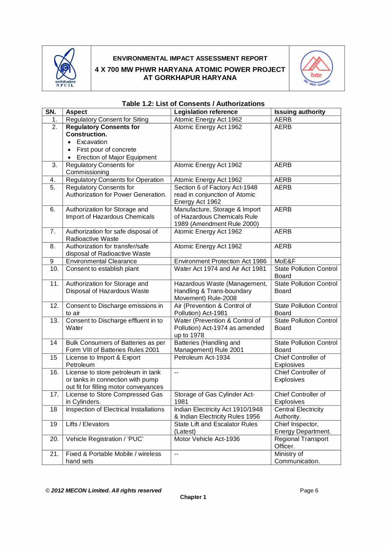
ENVIRONMENTAL IMPACT ASSESSMENT REPORT
4 X 700 MW PHWR HARYANA ATOMIC POWER PROJECT AT GORKHAPUR HARYANA
© 2012 MECON Limited. All rights reserved Page 6
Chapter 1
Table 1.2: List of Consents / Authorizations SN. Aspect Legislation reference Issuing authority
1. Regulatory Consent for Siting Atomic Energy Act 1962 AERB 2. Regulatory Consents for
Construction. Excavation First pour of concrete Erection of Major Equipment
Atomic Energy Act 1962 AERB
3. Regulatory Consents for Commissioning
Atomic Energy Act 1962 AERB
4. Regulatory Consents for Operation Atomic Energy Act 1962 AERB 5. Regulatory Consents for
Authorization for Power Generation. Section 6 of Factory Act-1948 read in conjunction of Atomic Energy Act 1962
AERB
6. Authorization for Storage and Import of Hazardous Chemicals
Manufacture, Storage & Import of Hazardous Chemicals Rule 1989 (Amendment Rule 2000)
AERB
7. Authorization for safe disposal of Radioactive Waste
Atomic Energy Act 1962 AERB
8. Authorization for transfer/safe disposal of Radioactive Waste
Atomic Energy Act 1962 AERB
9 Environmental Clearance Environment Protection Act 1986 MoE&F 10. Consent to establish plant Water Act 1974 and Air Act 1981 State Pollution Control
Board 11. Authorization for Storage and
Disposal of Hazardous Waste Hazardous Waste (Management, Handling & Trans-boundary Movement) Rule-2008
State Pollution Control Board
12. Consent to Discharge emissions in to air
Air (Prevention & Control of Pollution) Act-1981
State Pollution Control Board
13. Consent to Discharge effluent in to Water
Water (Prevention & Control of Pollution) Act-1974 as amended up to 1978
State Pollution Control Board
14 Bulk Consumers of Batteries as per Form VIII of Batteries Rules 2001
Batteries (Handling and Management) Rule 2001
State Pollution Control Board
15 License to Import & Export Petroleum
Petroleum Act-1934 Chief Controller of Explosives
16. License to store petroleum in tank or tanks in connection with pump out fit for filling motor conveyances
-- Chief Controller of Explosives
17. License to Store Compressed Gas in Cylinders.
Storage of Gas Cylinder Act-1981
Chief Controller of Explosives
18 Inspection of Electrical Installations Indian Electricity Act 1910/1948 & Indian Electricity Rules 1956
Central Electricity Authority.
19 Lifts / Elevators State Lift and Escalator Rules (Latest)
Chief Inspector, Energy Department.
20. Vehicle Registration / ‘PUC’ Motor Vehicle Act-1936 Regional Transport Officer.
21. Fixed & Portable Mobile / wireless hand sets
-- Ministry of Communication.

ENVIRONMENTAL IMPACT ASSESSMENT REPORT
4 X 700 MW PHWR HARYANA ATOMIC POWER PROJECT AT GORKHAPUR HARYANA
© 2012 MECON Limited. All rights reserved Page 7
Chapter 1
1.5 PROJECT BREIF
1.5.1 Importance of the Project National The development of power generation projects plays a key role in the economic growth of a country. Power is the most important and crucial factor for growth and development. Per capita electricity consumption is a major indicator of economic status of a country and an index of industrial prosperity. The development of the power sector in the country since independence has been predominantly through the thermal and hydro power plants. Electric power generation through nuclear power plant is essential and the need of the hour as coal reserves are limited and only hydro power generation will not be able to meet the growing countries demand of power in future. Hence setting up of new nuclear power plants is inevitable. Although several new power projects of diversified energy sources have been identified by Government of India with a view to bridge the gap between the demand and availability, only a few could be taken up for implementation due to financial and other constraints. This has resulted in large shortfall in the availability of both peak power and energy as per 17th Electric Power Survey carried out by Central Electricity Authority (CEA). The present demand for electrical power continues to grow and will continue to outstrip the available and planned generation capacity leading to chronic shortage of available power and energy in the future years. Nuclear power is the fourth-largest source of electricity in the country after thermal, hydroelectric and renewable sources of electricity. In the country, as on April 2012, 20 nuclear reactors with a total capacity of 4780 MWe are in operation - generating 4,680 (excluding Rajasthan Atomic Power Station (RAPS) 1 MWe while seven numbers of reactors are under construction with this the total installed capacity will be 10080 MWe. The nuclear power industry in the country is undergoing rapid expansion with plans to increase nuclear power output to 63,000 MWe by 2032. Considering the increasing demand of electricity, NPCIL intends to install a 4X700MWe PHWR atomic power project at Gorakhpur, District Fatehabad, Haryana. NPCIL is well positioned to fulfill its role in the nation’s quest for higher growth and development in the new millennium. Regional The growth of industry significantly contributes to economic growth of the Nation as well as to the region as it generates employment both directly and also due to development of infrastructure and market. The infrastructural and other social amenities grow in the region leading to overall development of the region. Establishment of the proposed atomic power plant at Fatehabad District will promote the overall development of the region and will reduce coal transportation from large distances for land locked Northern Grid.
ENVIRONMENTAL IMPACT ASSESSMENT REPORT
4 X 700 MW PHWR HARYANA ATOMIC POWER PROJECT AT GORKHAPUR HARYANA
© 2012 MECON Limited. All rights reserved Page 8
Chapter 1
The planned project will use state of art technology which will result in manufacture of products at a lower cost and more importantly in an environment friendly way.
1.5.2 Background
The site has been approved by Govt. of India based on the recommendation of the site selection committee constituted by Government of India for identifying suitable sites for Nuclear power projects and assigned to NPCIL through an authorization by Department of Atomic Energy (DAE) to establish NPP units (Annexure IA). During site selection / approval process, as a procedural requirement Haryana Government granted permission for Harayana Atomic Power Plant (HAPP) which implicitly grants administrative approval for acquisition of land and power connectivity for construction and operation of HAPP. MoE&F accorded Terms of Reference (TOR for conducting EIA study for the project at Gorakhpur site in the 9th meeting of the Expert Appraisal Committee (EAC) on Environmental Appraisal of Nuclear Power Projects of Ministry of Environment & Forest (MoE&F) held on 21st September 2010
1.5.3 Location of the Project
The proposed site is at village Gorakhpur, Tehsil Fatehabad, District Fatehabad, Haryana. The proposed site and study area of 10km radius is covered in the Survey of India Topo-sheets No. H43 P/7, H43 P/11, H43 P/8 & H 43 P/12. The geographical co-ordinates of the proposed site is longitude 750 37’ 56” E and latitude 290 26’ 30” N. The proposed site is about 28 km away in NW direction of Fatehabad District Headquarters. NH 10 passes about 6 km from the project site, connecting Hisar to Fatehabad. Hisar Railway station (North-Western Railways - connecting New Delhi to Firojpur and Jaipur to Amritsar) is about 30 kms on the southern side of the project site. The nearest Airports to the plant site are at Hisar (a small air port, presently used for Helicopter training purpose) located at a distance of about 40 km from the plant site and Indira Gandhi International Airport, Delhi is about 208 km from project site. The Bhakhara Canal (Fatehabad Branch) flows from east to west towards north close to the site. There is no major industry within 10 km of the project site. The Index map showing the location of the plant site is shown in Figure 2.1.
1.5.4 Nature and Size of the Project
The proposed project falls under the category of "Nuclear Power Project and Processing of Nuclear Fuel". The proposed plant of NPCIL will produce 4X700 MWe electricity.
1.6 SCOPE OF THE EIA STUDY
The following Terms of Reference (TOR) for EIA study (Copy of the same is presented in Annexure-IC, Volume II) has been finalised and approved in the 9th meeting of the

ENVIRONMENTAL IMPACT ASSESSMENT REPORT
4 X 700 MW PHWR HARYANA ATOMIC POWER PROJECT AT GORKHAPUR HARYANA
© 2012 MECON Limited. All rights reserved Page 9
Chapter 1
Expert Appraisal Committee on Environmental Appraisal of Nuclear Power Projects of Ministry of Environment & Forest held on 21st September 2010 (vide letter no: J-14011/2/2010-IA.II (N) dated 13.10.2010) and the point wise coverage of the TOR in the EIA report is referenced in the Table 1.3, “Index to MOE&F TOR Coverage In the EIA Report “.
Table 1.3 : Index to MoE&F TOR Coverage in the EIA Report SN TOR POINTS GIVEN BY MOE&F COVERAGE IN EIA REPORT 1. Based on the presentation made and held, the Committee
prescribed the following TORs for undertaking detailed EIA study :-
i) A note on site selection should be given in EIA report. Section 2.4, Chapter 2 ii) The data contained in EIA report for the ultimate capacity of
the plant. Chapter 2
iii) All the co-ordinates of the plant site as well as the township with toposheet should be given.
Section 2.17.1, Chapter 2.
iv) The study area should cover an area of 10km radius around the proposed site for conventional pollutants and 30 km radius for radiological parameters.
Section 4.1.3, Chapter 4.
v) Land use of the study area as well as project area shall be given separately.
Section 4.6, Chapter 4
vi) Location of any National Park, Sanctuary, Elephant / Tiger Reserve (existing as well as proposed), migratory routes, if any, within 10km of the project site shall be specified and marked on the map duly authenticated by Chief Wildlife Warden.
Section 4.2.7, Chapter 4. No National Park, Sanctuary, Elephant / Tiger Reserve (existing as well as proposed), migratory routes, present within 10km radius of the site.
vii) Land requirement for the project, along with usage for different purposes should be given. It should give information relating to right of way (ROW), if required for pipeline etc, as well as details of township.
Section 2.6, Chapter 2.
viii) Location of intake as well as outfall points (with coordinates) should be given.
Section 2.19.1, Table 2.5, Chapter 2
ix) Topography of the area should be given clearly indicating whether the site requires filling. If so, details of filling, quantity of fill material required, its source, transportation etc. should be given.
Section 5.4.2, Chapter 5
x) Impact on drainage of the area and surroundings should be given.
Refer Section 5.5.3.3, Chapter 5
xi) Information regarding surface hydrology and water regime and impact of the same, if any due to the project should be given.
Refer Cause 4.5, Chapter 4 & 5.5.3.2, Chapter 5
xii) One season site specific meteorological data shall be provided.
Refer Section 4.2.1, Chapter 4
xiii) One complete season AAQ data (except monsoon) to be given along with the dates of monitoring for the purpose of the EIA report for obtaining environmental clearance; however, data collection should continue for entire one year (three seasons). The parameters to be covered shall include PM2.5, PM10, SO2 and NOx. Besides, conventional pollutants
For AAQ refer Cause 4.2.2, Chapter 4. For radio-nuclides and background natural radio activity, Section 4.3, Chapter

ENVIRONMENTAL IMPACT ASSESSMENT REPORT
4 X 700 MW PHWR HARYANA ATOMIC POWER PROJECT AT GORKHAPUR HARYANA
© 2012 MECON Limited. All rights reserved Page 10
Chapter 1
SN TOR POINTS GIVEN BY MOE&F COVERAGE IN EIA REPORT information on long lived radio nuclides and background natural radio activity, gross alpha and gross beta levels should also be given. The location of the monitoring stations should be so decided so as to take in to consideration the pre-dominant wind direction, population zone and sensitive receptors including reserved forests. There should be at least one monitoring station in the predominant down wind direction at a location where maximum ground level concentration is likely to occur. Baseline data on noise levels may also be generated.
4. For baseline noise levels refer Section 4.2.3., Chapter 4.
xiv) Impact of the project on the AAQ of the area. Details of the model used and the input data used for modelling should also be provided. The air project site, habitation nearby, sensitive receptors, if any. The wind roses should also be shown on this map. Levels due to radioactive releases should be predicted and radiation dose there from at the fence post should also be worked out.
For predicted AAQ refer Section 5.5.3, Chapter 5. Predicted radiological releases Section 5.5.2 Chapter 5.
xv) Source of water and its availability. Commitment regarding availability of requisite quantity of water from the competent authority. The availability of water during canal closure should also be detailed and discussed in the report. It may clearly be stated whether any groundwater is to be used in the project or township. If so, detailed hydro-geological study should be carried out.
Refer Cause 2.19, Chapter 2
xvi) Details of rainwater harvesting and how it will be used in the plant.
Section 2.28.5, Chapter 2
xvii) Optimization of COC should be done for water conservation. Other water conservation measures proposed in the project should also be given. Quality of water requirement of the project should be optimized.
Section 2.19.3, Chapter 2
xviii) Details of water balance taking into account reuse and re-circulation of effluents.
Section 2.19.2, Chapter 2
xix) Details of greenbelt i.e. land with not less than 1500 trees per ha giving details of species, width of plantation, planning schedule etc.
Section 6.4, Chapter 6
xx) Detailed R&R plan/compensation package in consonance with the National / State R&R Policy for the project affected people including that due to fuel transportation system/pipeline and their ROW, if any, shall be prepared taking into account the socio economic status of the area, homestead oustees, land oustees, landless laborers.
Section 5.2, Chapter 5 No ROW required
xxi) Details of flora and fauna duly authenticated should be provided. In case of any scheduled fauna, conservation plan should be provided.
Section 4.2.6, Chapter 4.
xxii) Details regarding waste management, liquid and solid waste (conventional and radioactive) should be given in the EIA report.
Refer Section 5.3 & 5.3.4, Chapter 5, page 2 & 21.
xxiii) Details regarding storage and management of spent fuel should be given.
Refer Section 6.3.3.4, Chapter 6
xxiv) Details regarding storage of hazardous chemical including Section 9.4.1, Chapter 9.

ENVIRONMENTAL IMPACT ASSESSMENT REPORT
4 X 700 MW PHWR HARYANA ATOMIC POWER PROJECT AT GORKHAPUR HARYANA
© 2012 MECON Limited. All rights reserved Page 11
Chapter 1
SN TOR POINTS GIVEN BY MOE&F COVERAGE IN EIA REPORT maximum inventory to be stored at any point of time should be given.
xxv) Detailed risk assessment and disaster management plan should be given. The risk contours may be plotted on location map.
Refer Chapter 9
xxvi) Issues relating to de-commissioning of the plant and the related environmental issues should be discussed.
Section 5.8, Chapter 5,
xxvii) Demographic data of the study area as well as pre-project health survey of the population in study area around the project site should be collected.
Section 8.2.4, Chapter 8.
xxviii) Detailed environmental management plan to mitigate the adverse environmental impacts due to the project should be given. It should also include possibility of use of solar energy for the project including measures for energy conservation.
Chapter 6, 7 & 11 For Solar energy – refer Sections 2.28.6 & 2.28.7, Chapter 2.
xxix) Details of post project monitoring should also include in the EIA report.
Refer Chapter 7 & 11.
xxx) Details regarding infrastructure facilities such as sanitation, fuel, restroom, medical facilities, safety during construction phase etc. to be provided to the labour force during construction as well as to the casual workers including truck drivers during operation phase.
Section 5.4.1, Chapter 5. Section 5.5.6, Chapter 5.
xxxi) Public hearing points raised and commitment of the project proponent on the same. An action plan to address the issues raised during public hearing and the necessary allocation of funds for the same should be provided.
To be addressed after public hearing
xxxii) Measures of socio economic influence to the local community proposed to be provided by project proponent. As far as possible, quantitative dimension to be given.
Section 8.2.8, Chapter 8.
xxxiii) Impact of the project on local infrastructure of the area such as road network and whether any additional infrastructure would need to be constructed and the agency responsible for the same with time frame particularly keeping in view the transportation of over sized consignments should be given.
Sections 5.5.3.8 & 5.5.3.9, Chapter 5
xxxiv) EMP to mitigate the adverse impacts due to the project along with item wise cost of its implementation.
Refer Chapter 7
xxxv) Any litigation pending against the project and /or any direction /order passed by any Court of Law against the project, if so, details thereof.
Nil
2. In respect of the township, the following TORs are prescribed for addressing the same in the EIA report.
i) A site plan showing the project site and its surroundings with physical features and topographical details, such as land use, contours and drainage pattern, along with photographs of the site from all four sides, shall be examined in detail.
Section 2.24.1, Chapter 2.
ii) If the site is low lying and will require extra earth, examine the quantity required and identify the area from where the earth will be borrowed and whether any permission will be required or not.
Section 2.27.3, Chapter 2.
iii) Examine in detail the proposed site with reference to impact Section 2.27 and 2.28,

ENVIRONMENTAL IMPACT ASSESSMENT REPORT
4 X 700 MW PHWR HARYANA ATOMIC POWER PROJECT AT GORKHAPUR HARYANA
© 2012 MECON Limited. All rights reserved Page 12
Chapter 1
SN TOR POINTS GIVEN BY MOE&F COVERAGE IN EIA REPORT on infrastructure covering water supply, storm water drainage, sewerage, power, etc., and the disposal of treated/ raw wastes from the complex on land/water body and into sewerage system.
Chapter 2.
iv) Consider soil characteristics and permeability for rainwater harvesting proposals, which should be made with due safeguards for ground water quality. Maximise recycling of water and utilisation of rainwater.
Section 2.28.5, Chapter 2
v) Provision should be made for guard pond and other provisions for safety against failure in the operation of wastewater treatment facilities. Identify acceptable outfall for treated effluent.
Section 2.28.1, Chapter 2.
vi) Examine existing education and health facilities, police and other services and include adequate provisions in the proposal.
Section 2.28.4, Chapter2.
vii) Study the existing flora and fauna of the area and the impact of the project on them.
For details of Flora & Fauna – refer Section 4.2.6, Chapter 4 & Section 2.27.2, Chapter 2.
viii) Landscape plan, green belts and open spaces should be described.
Section 2.28.9 & 2.28.10, Chapter 2.
ix) Assess soil erosion in view of the soil characteristics, topography and rainfall pattern.
Section 2.27.1
x) Application of renewable energy/alternate energy, such as solar and wind energy may be described including solar water heating. Provide for conservation of resources, energy efficiency and use of renewable sources of energy in the light of ECBC code.
Section 2.28.6 and 2.28.7, Chapter 2.
xi) Arrangements for waste management may be described as also the common facilities for waste collection, treatment, recycling and disposal of all effluent, emission and refuse including MSW. Identification of recyclable wastes and waste utilisation arrangements may be made.
Sections 2.28.1 & 2.28.2, Chapter 2.
xii) Traffic management plan including parking and loading / unloading areas may be described. Traffic survey should be carried out both on weekdays and weekend.
Section 2.28.2, Chapter 2 and Section 5.5.3.8, Chapter 5.
xiii) Use of local building materials should be described. Section 2.27.3, Chapter 2 and Section 5.4.1, Chapter 5.
xiv) Application of resettlement and rehabilitation policy may be described. Project affected persons should be identified and rehabilitation and resettlement plan should be prepared.
Section 5.2, Chapter 5, and Section 2.26.1, Chapter 2.
xv) Examine separately the details for construction and operation phases both for Environmental Management Plan and Environmental Monitoring Plan.
Refer Chapter 6, 7 & 11
xvi) Examine and prepare in detail the Disaster Management Plan and emergency Evacuation Plan for natural and manmade disasters like earthquakes, cyclones/flooding, Tsunami and terrorists attack.
Section 2.28.11 and Chapter 9
3. Besides the above, the below mentioned points will also be followed:-
a) All the information contained in various project documents Followed in the report

ENVIRONMENTAL IMPACT ASSESSMENT REPORT
4 X 700 MW PHWR HARYANA ATOMIC POWER PROJECT AT GORKHAPUR HARYANA
© 2012 MECON Limited. All rights reserved Page 13
Chapter 1
SN TOR POINTS GIVEN BY MOE&F COVERAGE IN EIA REPORT should be rechecked and reconciled.
b) All documents to be properly referenced with index, page numbers and continuous page numbering.
Followed in the report
c) Where data are presented in the report especially in tables, the period in which the data were collected and the sources should be indicated.
Followed in the report
1.7 BASIC DATA GENERATION, FIELD STUDIES AND DATA COLLECTION
This report has been prepared on the basis of three months baseline environmental data monitored during March – May 2011 by field study. The data includes meteorological conditions, ambient air quality, noise, water quality and soil quality. Site survey has been conducted for studying the flora and fauna, socio-economic conditions including public consultation, land use, hydrology, geology, ecology etc. Additional information is also collected from several agencies and departments, both under State and Central Governments pertaining to above. The collected data have been analysed in detail for identifying, predicting and evaluating the environmental impacts of the proposed project. The maximum anticipated impacts on environment are assessed and suitable environmental management plan has been suggested. In Addition, following special studies have been carried out by independent institutes / agencies, organized by NPCIL for generation of important baseline data / specific information required for the subject EIA study, viz. Pre–operational baseline radiological survey in the area of 30 km around the project
site by Health Physics Division (HPD), Bhabha Atomic Research Centre (BARC), in the year 2011.
Estimation of Design Basis Flood and Safe Grade Elevation for Nuclear Power Project at Gorakhpur, Haryana, by National Institute Of Hydrology, Roorkee, Uttarakhand
Provisional public dose calculation for Twin –unit 700 MWe PHWR station at Gorakhpur, Haryana, by Health Physics Division, BARC.
1.8 STRUCTURE OF THE EIA REPORT
This report contains information on the existing environment and evaluates the predicted environmental and socio-economic impacts of the proposed project. A detailed coverage of background environmental quality, pollution sources, anticipated environmental impacts (including socio-economic impacts) and mitigation measures, environmental monitoring programme, additional studies, project benefits, environmental monitoring plan and all related aspects have been covered in this report. The structure of the EIA report has been made as per the requirements of Environmental Impact Assessment (EIA) Notification 2006 (S. O. 1533). The subject EIA report has been organized in two volumes viz. Volume I, which consists of main contents of the EIA

ENVIRONMENTAL IMPACT ASSESSMENT REPORT
4 X 700 MW PHWR HARYANA ATOMIC POWER PROJECT AT GORKHAPUR HARYANA
© 2012 MECON Limited. All rights reserved Page 14
Chapter 1
studies, whereas the Volume II contains the special study reports (as Annexures) as carried out by various independent institutes / agencies and other supporting documents.
EIA Volume I consists of the following chapters: Executive Summary Chapter 1 Introduction Chapter 2 Project Description Chapter 3 Description of the Environment Chapter 4 Anticipated Environmental Impacts and Mitigation Measures Chapter 5 Technologial details of environmental protection measures Chapter 6 Environmental Monitoring Programme Chapter 7 Additional Studies: Public consultation and Socio-economic Studies Chapter 8 Additional Studies: Risk Assessment Studies Chapter 9 Project Benefits Chapter 10 Environmental Management Plan (EMP) Chapter 11 Summary and Conclusion Chapter 12 Disclosure of Consultant Engaged EIA Volume II The Volume II contains special study reports from the Institutes / Agencies including supporting documents / Annexures of the Volume I (the main EIA study report) as presented below :
Annexure IA : In-principal Approval for Harayana Site form Central Government Annexure IB : Haryana R & R Policy 2010 Annexure IC MoEF Approved TOR for Haryana Atomic Power Project. Annexure ID Part of presentation to MoEF for approval of TOR Annexure II : Flood Analysis Report & Safe Grade Elevation of the Site Annexure III : Commitment of Bhakhra Canal Water Availability from Haryana
Irrigation Department Authorities Annexure IVA : Detailed Summer Season Meteorological Data at Gorakhpur Annexure IVB : Detailed Summer Season Ambient Air Quality Data in Study Area Annexure IVC : Authentication of flora and fauna from State Forest Department. Annexure IVD : Authentication of Wild Life that no National Park or Wildlife
Sanctuary exists within the Study Area Annexure V : Provisional Public Dose calculation for Twin –unit 700 Mwe PHWR Station at Gorkhpur, Haryana, HPD, BARC Annexure VI : Proceedings of Public Hearing and Commitments - English Annexure VII : Proceedings of Public Hearing and Commitments – Hindi

ENVIRONMENTAL IMPACT ASSESSMENT REPORT
4 X 700 MW PHWR HARYANA ATOMIC POWER PROJECT AT GORAKHPUR HARYANA
© 2012 MECON Limited. All rights reserved Page 15
Chapter 2
CHAPTER 2 : PROJECT DESCRIPTION 2.1 INTRODUCTION
Nuclear Power Corporation of India Limited has developed comprehensive capability in the Design, Construction, and Operation & Maintenance of Pressurized Heavy Water Reactors (PHWRs) type of nuclear power reactors. Considering the scenario of power demand in the country, NPCIL have planned to set up a 4X700 MWe Atomic Power Project at Gorakhpur Village, in the district of Fatehabad, Haryana.
2.2 TYPE OF PROJECT
The proposed project falls under the project or activity type - "Nuclear Power Project and Processing of Nuclear Fuel" falling under Category A (as per Ministry of Environment and Forests (MoE&F) EIA Notification 2006), which requires prior environmental clearance from the Central Government in the MoE&F. The proposed plant of NPCIL will produce 4X700 MWe electricity.
2.3 NEED FOR THE PROJECT
The project is needed to fulfill the power demand of the country and to fulfill the chronic shortage of available power and energy in the future years. In the country, as on April 2012, 20 nuclear reactors with a total capacity of 4780 MWe are in operation - generating 4,680 (excluding Rajasthan Atomic Power Station (RAPS) 1 MWe while seven numbers of reactors are under construction with this the total installed capacity will be 10080 MWe. The nuclear power industry in the country is undergoing rapid expansion with plans to increase nuclear power output to 63,000 MWe by 2032. Considering the increasing demand of electricity and future plan of Government of India, NPCIL intends to install a 4X700MWe PHWR atomic power project at Gorakhpur, Fatehabad District, Haryana. NPCIL is well positioned to fulfill its role in the nation’s quest for higher growth and development in the new millennium.
2.4 SITE SELECTION CONSIDERATIONS
The Gorakhpur, Fatehabad, Haryana site is considered suitable for setting up multi-unit NPPs of PHWR category and approved by Government of India in October, 2009. The site selection is based on the recommendations of Site Selection Committee, (Constituted by Government of India / Department of Atomic Energy), which is one of the input among the several other considerations to Atomic Energy Commission (AEC) and Govt. of India to take final decision on particular site. The site so approved is assigned to NPCIL through an authorization by Department of Atomic Energy to take further actions for obtaining statutory clearances from various agencies / Govt. Organizations to establish NPP units at such site. DAE Authorisation to NPCIL for Gorakhpur site is presented as Annexure IA. The Site Selection Committee had surveyed the Gorakhpur site to establish Nuclear Power Project (NPP) by analyzing a number of parameters as listed hereunder and submitted their recommendations to Govt. of India. As a procedural requirement the State Government offers a number of sites, complying with the requirements of “NPP site” and subsequently site selection committee surveys and

ENVIRONMENTAL IMPACT ASSESSMENT REPORT
4 X 700 MW PHWR HARYANA ATOMIC POWER PROJECT AT GORAKHPUR HARYANA
© 2012 MECON Limited. All rights reserved Page 16
Chapter 2
analyses the site with respect to the requirements of NPPs. As the State Government Haryana has given umbrella consent for establishment of HAPP at Gorakhpur, the Government subsequently facilitates the administrative approval for acquisition of private and government land and power connectivity for construction and operation of HAPP. The parameters analysed by site selection committee while selecting a candidate site:
a. Location and General Area b. Land availability c. Available source of cooling water d. Electrical System e. Meteorology f. Population Distribution g. Land Use h. Foundation Conditions & Seismicity i. Flood Analysis & Safe grade elevation at site etc. j. Solid Waste Management & Radiological Burden k. Proper access for transportation of heavy / over dimensional equipment. l. Environment aspects
The site selection committee, during process of site evaluation and while submitting their recommendations in June 2003, had recommended Gorakhpur site suitable for setting up of four units of 700 MWe PHWRs in two stages of 2X700MWe PHWRs.
The following are some of the salient features of the proposed site for Atomic Power Project: Site Location : (i) The adequate land required to set up multi unit APPs at Gorakhpur for plant site and
residential complex is being acquired in one go. The land to be acquired for the plant site and the township involves no displacement of homestead population. Most of the land being acquired for residential complex is barren.
(ii) Water availability and drawl of cooling water from Fatehabad branch of Bhakra canal
is assured at the site by State Government of Haryana. (iii) The site is located in the Indo-gangetic alluvial plains with soil made up of both older
and newer alluvium with a thickness estimated to be of the order of about 300m. The above geological formations are favorable for foundation conditions as required for APP.
Site Seismicity : (iv) The site area lies in Seismic Zone-III in the Seismic Zoning Map of India. The
seismo-tectonic study has concluded that there is no capable fault within five kilometers of the project site. The site is engineer-able from seismo-tectonic considerations.
Site Elevation :

ENVIRONMENTAL IMPACT ASSESSMENT REPORT
4 X 700 MW PHWR HARYANA ATOMIC POWER PROJECT AT GORAKHPUR HARYANA
© 2012 MECON Limited. All rights reserved Page 17
Chapter 2
(v) The ground elevation at plant site varies from RL + 215 m to RL + 218 m. The detailed analysis / studies have been carried out by National Institute of Hydrology, Roorkee to arrive at the safe grade elevation for proposed HAPP due to flood. The maximum flood elevation level due to severe most anywhere within the plant site as derived through model simulation is 218.1m and has been considered as base flood elevation and flood submersion line. A free board of 1.0 m has been assumed and the safe grade elevation has been worked out to be 219.1 m. The safe grade elevation of 219.1 m is recommended for proposed HAPP site. The detailed report on “Estimation of Design Basis Flood and Safe Grade Elevation for Nuclear Power Project at Gorakhpur, Haryana” as studied by National Institute of Hydrology, Roorkee, is enclosed as Annexure II.
Power Evacuation : (vi) Power evacuation “in principle” is feasible for 2800 MWe power from site. The
Power generated at HAPP will be evacuated through 400 kv transmission system. The number of transmission outlets and their destination will be finalized taking into account share of beneficial state in due course after a detailed power system studies are carried out by PGCIL and approved by the concern authorities.
Population Distribution : (vii) As per the estimates based on census data 2001, the average population density
within 10 km around the site as estimated for 2011 is about 264 persons / sq .km as compared to the population density of Haryana State of 478 per km2.
Site Approachability : (viii) The nearest National Highway is NH-10 at 6 km distance from the site. The nearest
railway station Uklana Mandi (23 km) north-east of the project site on Northern railway Jalandhar Doab extension.
(ix) The Over Dimensional Consignment (ODC) of APP equipments of HAPP will be transported by road. Separate studies will be required to be carried out for improvements of roads for transport of normal consignment of APP units at HAPP.
Site Land-use : (x) The proposed site for the project is agricultural land whereas the township is almost
barren with no ecologically sensitive areas like National Parks or wild life sanctuary exists up to 10km from the site. No industries handling toxic chemicals or explosives are reported to exist within 10 km. There are no railways sidings or road transport depots within 10 km. There are no civil or military airports within 50 km around the site (the nearest Airports to the plant site is at Hisar about 33 km from the site, small air port - not used for commercial flights). In general, the industrial activities in the area are practically nil and as such, impact on environment arising out of human utilization is negligible .

ENVIRONMENTAL IMPACT ASSESSMENT REPORT
4 X 700 MW PHWR HARYANA ATOMIC POWER PROJECT AT GORAKHPUR HARYANA
© 2012 MECON Limited. All rights reserved Page 18
Chapter 2
2.5 PROJECT LOCATION
The project site is located in Gorakhpur Village in Bhuna Block of Tehsil, Sub-division and District Fatehabad of Haryana State. The proposed site is located at geographical co-ordinates of longitude 750 37’ 56” E and latitude 290 26’ 30” N. and situated about 215m -218 m above mean sea level. The site is about 28 km in SE direction of Fatehabad town which is the district head-quarter of Fatehabad district. The site is located about 6.0 km from NH10, which connects Hisar to Fatehabad. The site is connected to NH10 by the Kharakheri-Gorakhpur road. The nearest railway station is Uklana Mandi (23 km) north-east of the project site on Northern railway Jalandhar Doab extension. Rail head Adampur at a distance of 32 km south-western of the site on Northern railway Rewari-Bhatinda section (Hisar-Sirsa Broad-Gauge section). The road from Adampur station to the site is 22m wide good road. The North Railway track, New Delhi – Firojpur and Jaipur to Amritsar passes through Rail Station at Hisar, situated about 33 km on the SSE of the project site. The Narwana or Jakhal Rail Junction is located on the Delhi-Bhatinda sections of the Northern Railway, towards NE of the project site at about 33km from the project site. The above Railway Stations caters to the commuter needs and transportation of goods in the region. The nearest Airports to the plant site are at Hisar (a small air port, presently used for Helicopter training purpose) located at a distance of about 40 km from the plant site and Indira Gandhi International Airport, Delhi is about 208 km from project site. The Bhakhara Canal (Fatehabad Branch) flows from east to west towards north close to the site. There is no major industry within the study area. The nearest coal fields are at Patha Khera in MP, at a distance of about 1185 km from the site via Adampur-Hisar-New Delhi-Itarsi-Amla. The nearest distance of site from the international border is about 180km. The Index map showing the location of the plant site is shown in Figure 2.1. There are no installation for handling, storing or transporting inflammable/toxic material within a distance of 10km. There is no major railway siding or road transport depot within 10 km of the site. There is no place of historical importance within 10 km from the proposed site.

ENVIRONMENTAL IMPACT ASSESSMENT REPORT
4 X 700 MW PHWR HARYANA ATOMIC POWER PROJECT AT GORAKHPUR HARYANA
© 2012 MECON Limited. All rights reserved Page 19
Chapter 2
Figure 2.1: Proposed Project Site at Village Gorakhpur, District Fatehabad, Haryana
Proposed Site
NH
NH Other Roads Canals
Proposed Site
NH
NH Other Roads Canals

ENVIRONMENTAL IMPACT ASSESSMENT REPORT
4 X 700 MW PHWR HARYANA ATOMIC POWER PROJECT AT GORAKHPUR HARYANA
© 2012 MECON Limited. All rights reserved Page 20
Chapter 2
2.6 LAND REQUIREMENT
2.6.1 Land Area
The land requirement for the proposed project is set to about 1318 acres (533.5 hectares) and that required for housing colonies of plant personnel and CISF personnel is about 185.42 acres (75.04 hectares). The land for the power plant (534 ha) site comprises 1273.2 acres or 515.24 ha of land under double crop agricultural category. The remaining 32 ha of land is not cultivable (which includes 6.0 ha of low lying area, which will be suitably used). The land at the township comprises mostly barren land. The total land required 1503.5 acres (608.48 ha) for the project is private land (Table 2.1a).
Table 2.1a: Break-up of Land in different Villages – to be Acquired Atomic Power Plant (Acres) Township (Acres) SN. Village
Private Government Total Private Government Total 1 Gorakhpur 1313.68 0 1313.68 0 0 0 2 Kajhalheri 4.46 0 4.46 0 0 0 3 Bodapal 0 0 0 185.42 0 185.42 Total 1318.2 0 1318.2 185.42 0 185.42 The village wise actual land requirement for the project, classification of land and Rehabilitation and Resettlement (R&R) issues are given in Table 2.1b.
Table 2.1b: Actual Land Requirement, Classification of Land and R&R Issues
Agricultural Land
Non-agricultural
land
Total Land Affected People (Khatedar)
R&R Issues SN Name of Village
Acres Ha. Acres Ha. Acres Ha. Numbers 1 Gorakhpur 1270.49 514.16 43.19 17.48 1313.68 531.64 844 2 Kajhalheri 2.68 1.08 1.79 0.72 4.46 1.81 10 3 Bodapal 70.23 28.42 115.19 46.61 185.42 75.04 125 Total 1343.4 543.66 160.17 64.81 1503.56 608.48 979
Land to be acquired through Haryana Government taking in to account the R&R issues of Haryana R&R policy 2010.
2.6.2 Resettlement and Rehabilitation of PAPs for the Land under Acquisition Process
For the proposed project the Project Affected Persons (PAPs) includes only land Oustees and no displaced population is involved. The total PAPs involved in the project is 979. The village-wise breakup of land and Project Affected People (PAPs) of the land under process of acquisition for the proposed plant is given in Table 2.1b.

ENVIRONMENTAL IMPACT ASSESSMENT REPORT
4 X 700 MW PHWR HARYANA ATOMIC POWER PROJECT AT GORAKHPUR HARYANA
© 2012 MECON Limited. All rights reserved Page 21
Chapter 2
2.6.3 Land Acquisition
Section 4 notification completed. Objections received under section 5(a) addressed by district authorities. Section 6 notification issued, meaning thereby that the land is being acquired for public purpose.
There are only land oustees and no homestead oustees involved. Compensation to the land oustees will be paid as per the Haryana R & R Policy 2010, enclosed as Annexure IB.
2.7 SIZE OR MAGNITUDE OF OPERATION
The proposed Atomic Power Project is intended to setup 4x700 MWe Pressurised Heavy Water Reactor (PHWR) units. The major equipments needed are Steam Generators, End-Shield, Calandria, Coolant Channels, End Fittings, Primary Coolant pumps, Heat Exchangers, Fuelling Machine components, etc. These equipments will be housed in Nuclear buildings consisting of: Reactor Building (RB) and Reactor Auxiliary Building (RAB) house the main reactor
and associated process systems, Safety related Buildings other than Nuclear Building consisting of Control Building
(CB), Station Auxiliary Building (SABs), Ventilation Stack with Monitoring Room and Station Auxiliary Buildings (SABs), D2O Upgrading Plant Building, Waste Management Facility and Exhaust Ventilation, Induced Draught Cooling Towers, Safety Related Pump House (SRPH), Fire Water Pump House, Underground Tunnels and Trenches, Diesel Oil Storage Area (DOSA), Emergency Makeup Water Pond, Covered Passage, etc as per the design features of the plant.
Power evacuation “in principle” is feasible for 2800 MWe power from site. The Power generated at HAPP will be evacuated through 400 kv transmission system. The number of transmission outlets and their destination will be finalized taking into account share of beneficial state in due course after a detailed power system studies are carried out by PGCIL and approved by the concern authorities. A residential colony has been envisaged for the proposed project for accommodating 1700 employees. The total land area required for the same is 186 acres. A sewage treatment plant of capacity 1.0 MLD will be installed to treat the sewage water emanating from the township. The proposed township and the proposed power plant is depicted in 10 km locator map of the study area in No. MEC/11/S2/Q6SY/01.
2.8 PROPOSED SCHEDULE FOR APPROVAL AND IMPLEMENTATION
Construction of the project will be taken up in two stages of 2X700 MWe each. Planned schedule for the proposed two units of 1st stage is given in Table 2.2. Subsequent two units are expected to be four years later. The 1st stage project will be commissioned in 60 months from the “Zero-Date” which is reckoned as start of construction activities at site.

ENVIRONMENTAL IMPACT ASSESSMENT REPORT
4 X 700 MW PHWR HARYANA ATOMIC POWER PROJECT AT GORAKHPUR HARYANA
© 2012 MECON Limited. All rights reserved Page 22
Chapter 2
Table 2.2: Time Schedule for the First Two Units of the Project SN Name of Milestone First Unit of the twin unit
project Completion date Units 2X700 1 Land Acquisition and Statuary Clearances 2011- July 2013 2 Start of Construction Activities June 2015 3 Completion of Construction & start of operation
Unit 1 Unit 2
Dec 2020 June 2021
2.9 MANPOWER PLANNING
During construction stage maximum of 8000 persons (when construction of stage-I will be nearing completion and construction of stage-II will be started) will be temporarily deployed. Whereas during operation and maintenance stage the manpower deployed will be as follows:
At the beginning of Stage I : 760 By the completion of Stage I : 1620 By the completion of Stage II : 1700
The manpower includes technical and general administration needs. The estimate covers the top management, middle and junior level executives and other supporting staff. The estimate, however, does not cover the personnel for township, medical facilities, etc.
2.10 TECHNOLOGY / PROCESS DESCRIPTION
2.10.1 Salient Features
The capacity of the proposed plant is 4X700 MWe PHWR. A PHWR is a nuclear power reactor, commonly using natural uranium as fuel, which uses heavy water (deuterium oxide D2O) as its coolant and moderator. The heavy water coolant is kept under pressure in order to raise its boiling point, allowing it to be heated to higher temperatures without boiling, much as in a PWR1 (Pressurised Water Reactor). While heavy water is significantly more expensive than ordinary light water, it yields greatly enhanced neutron economy, allowing the reactor to operate without fuel enrichment facilities (mitigating the additional capital cost of the heavy water) and generally enhancing the ability of the reactor to efficiently make use of fuel . In the proposed project Natural uranium oxide will be used as fuel and heavy water (D2O) will be used as coolant and moderator for the reactor. Refueling of the reactor will
1 Pressurized water reactors (PWRs): In a PWR the primary coolant (water) is pumped under high pressure to the reactor core where it is heated by the energy generated by the fission of atoms. The heated water then flows to a steam generator where it transfers its thermal energy to a secondary system where steam is generated and flows to turbines which, in turn, spins an electric generator. PWRs use ordinary light water as both coolant and neutron moderator.

ENVIRONMENTAL IMPACT ASSESSMENT REPORT
4 X 700 MW PHWR HARYANA ATOMIC POWER PROJECT AT GORAKHPUR HARYANA
© 2012 MECON Limited. All rights reserved Page 23
Chapter 2
be carried out "on-power". Steam generators supply nearly dry saturated steam to the turbine. Turbine is a tandem compound machine directly coupled to an electrical generator, which produces electricity. Generator voltage is stepped up by the generator transformer, which in turn is connected, to a switchyard. Generated power is transmitted to the grid from the nuclear power station at 400 kV. The concept of defense-in-depth is adopted in design of safety systems. Provision of multiple barriers, double containment structures with steel liner on inner containment wall of Reactor Building, containment spray cooling system, emergency core cooling system, reactor shut down systems etc. as engineered safety systems ensure safe operation of reactor. Reactor protection system ensures shutdown requirements through two independent fast acting shut down systems. Reactor regulating system enables automatic control of reactor power and maintains neutron flux profile.
2.10.2 Engineering
The design of the proposed 2x700 MWe PHWRs of Haryana Atomic Power Projects (HAPP 1&2) will be identical to the design of 700MWe units under construction at Kakrapar Atomic Power Project (KAPP 3&4) except for the site specific changes that are mainly associated with plant water systems and power evacuation system. The major components / equipments comprises of Steam Generators, End-Shield, Calandria, Coolant Channels, End Fittings, Primary Coolant pumps, Heat Exchangers, Fuelling Machine components, etc. However, slight modifications in the above equipments will be required as that used for KAPP 3&4, depending on the site conditions.
2.11 PROJECT DETAILS 2.11.1 Safety Objectives and Principles
Objectives The basic objective of nuclear power plants safety is to ensure protection of individuals, society and the environment from radiation. Accordingly, the design, construction and operation of nuclear power plants are aimed at achieving the following safety goals: 1. During routine operation, to minimize the radiation doses to plant personnel and to
members of the public in accordance with the principle of `As low as Reasonably Achievable' (ALARA), and in any case not in excess of the prescribed limits, specified by AERB.
2. To minimize the risk to public from accidental release of radioactivity, if any under abnormal/postulated accident conditions for scenarios within the design basis, the

ENVIRONMENTAL IMPACT ASSESSMENT REPORT
4 X 700 MW PHWR HARYANA ATOMIC POWER PROJECT AT GORAKHPUR HARYANA
© 2012 MECON Limited. All rights reserved Page 24
Chapter 2
calculated releases shall be within specified release limits. This requirement is met by ensuring that plant conditions associated with high radiological consequences have low likelihood of occurrence, and plant condition with a high likelihood of occurrence have only small or no radiological consequences.
3. Incorporate emergency preparedness measures to deal with situations arising out of highly unlikely ‘Beyond Design Basis Accidents’.
4. To meet nuclear security requirements as specified in AERB manual on security
Principles and Guidelines The safety goal of protection of public from accidental release of radioactivity is achieved by adherence to the following well-established principles and guidelines: 1. Application of defense-in-depth approach, incorporating several echelons of defense
viz. Sound design, construction and operation to prevent failures and deviation from
normal operation. To detect and intercept incipient failures and deviation from normal operation
conditions, in order to prevent these from escalating into accidents. To limit the consequences of accident conditions. In addition to the above, for more severe events, protection of the public by
making use of ultimate safety capability of the plant, and appropriate emergency preparedness plan.
2. Application of defense-in-depth concept to containment of radioactive material, by a series of physical barriers, each backing the others.
3. Provision of more than one means / systems for performance of each of the three safety functions viz. shutdown of reactor, core cooling, and containment of radioactivity.
4. Provision of redundancy in systems important to safety having mitigation function, including safety systems, such that at least minimum safety function can be performed even in the event of failure of a single active component in the system.
5. Specifying unavailability targets for safety systems. 6. Provision of physical and functional separation, and independence to the extent
practicable, among/between following systems including their services (including cabling etc.) to prevent common cause failures: i) Between process systems and related safety systems. ii) Among systems performing same safety function. iii) Among redundant components within a system.
7. Consideration given at all stages of design for logics and instrumentation to fail in the safe direction.
8. Provision of periodic testability of active components in systems important to safety having mitigation function, preferably on-power.
9. Provision of periodic in-service inspection of components important to safety.
Safety Analysis To demonstrate that the safety objective of protection of the public from accidental
ENVIRONMENTAL IMPACT ASSESSMENT REPORT
4 X 700 MW PHWR HARYANA ATOMIC POWER PROJECT AT GORAKHPUR HARYANA
© 2012 MECON Limited. All rights reserved Page 25
Chapter 2
releases is met, safety analysis is performed to evaluate the consequences of postulated initiating events, and event sequences. In the approach adopted here, the identification of design basis events is based on definition of `single' and `multiple' failures. A single failure is the failure of a plant process system/component. Multiple failure is a much more severe, and much less likely accident sequence involving a single process system failure plus simultaneous unavailability of a safety system*, which was meant to mitigate the effect of the particular process system failure. The various postulated accident scenarios considered are identified in terms of failures in, or of, individual systems. These failures may themselves be the initiating events, or be the result of some other initiating events, including external events. The influence of external events on system safety is taken care of by proper site selection and design basis. The results of the safety analysis for various postulated accidents, in terms of radiological consequences to the public, are checked to ensure that limits specified by AERB are not exceeded. For evaluation of the dose, from postulated accidents, inhalation and external dose are considered. Ingestion route is considered for LOCA condition. For severe accidents, ingestion route is not considered as appropriate counter measures are to be implemented as a part of emergency procedure. In addition to the evaluation of radiological consequences of design basis events/event sequences, an essential part of the safety analyses as performed here, is the reliability analysis of safety & safety related systems. Each safety system is designed to have unavailability targeted below 1x10⁻³ /yr.
2.11.2 Barriers to Radioactivity Release
The release of radioactivity to the environment and the public is prevented by incorporating a series of fission product barriers in the system. These are:
Fuel matrix Fuel sheath Primary Heat Transport System Containment Exclusion zone
Fuel:
The uranium dioxide (UO2) used for fuel is a ceramic with high melting point and chemically inert to water at operating conditions. So long as the ceramic fuel does not melt, the fission products remain entrapped in its matrix. During normal operation virtually all solid fission products are permanently retained in UO2 matrix and only a fraction of noble gases and volatile products diffuse into the inter space between fuel and cladding.
ENVIRONMENTAL IMPACT ASSESSMENT REPORT
4 X 700 MW PHWR HARYANA ATOMIC POWER PROJECT AT GORAKHPUR HARYANA
© 2012 MECON Limited. All rights reserved Page 26
Chapter 2
Fuel Sheath: Fuel Sheath also called fuel cladding, made of Zircaloy-2, encapsulates the fuel pellets. This forms the second barrier and is designed to withstand stresses resulting from UO2 expansion, fission gas pressure, external hydraulic pressure and mechanical loads imposed by fuel handling.
Primary Heat Transport System: The fuel bundles and coolant are contained in Primary Heat Transport (PHT) system. This is a closed system and forms the third barrier for fission product release.
Containment: The fourth barrier is the containment building which houses the reactor and associated nuclear systems. The containment is a leak tight pre-stressed concrete structure with quick isolation feature. The containment structures are designed to withstand maximum pressure and temperature generated by postulated accidents and maintains acceptably low leak rates consistent with specified dose limits following the postulated accident conditions. Containment system performs its functions in association with related engineered safety features (ESFs).
Exclusion zone:
The exclusion zone of 1.0 km is provided around the reactor building where no habitation is allower. This measure gives as added safety. Public domain starts from exclusion zone and dose limit to public is defined at exclusion zone boundary
2.11.3 Special Safety Requirements Radiation zoning: The entire operating island is divided into 3 distinct zones based on the contamination potential. These zones have been designated as Zone-1, Zone-2 and Zone-3 in the ascending order of contamination potential The Zone system ensure radiological safety to occupational worker.
2.11.4 Safety Classification
To ensure adequate safety to the public and plant site personnel, the plant design meets following general safety requirements. 1. The capability for safe shutdown of the reactor and maintaining it in the safe shut
down condition during and after all operational states and postulated accident conditions.
2. The capability to remove residual heat from the core after reactor shut down, and during and after all operational states and postulated accident conditions and maintain a cool-able geometry.

ENVIRONMENTAL IMPACT ASSESSMENT REPORT
4 X 700 MW PHWR HARYANA ATOMIC POWER PROJECT AT GORAKHPUR HARYANA
© 2012 MECON Limited. All rights reserved Page 27
Chapter 2
3. The capability to reduce the potential for the release of radioactive materials and ensure that releases are within the prescribed limits during and after all operational states and, postulated accident conditions.
4. To meet these requirements, systems, components and structures have to perform
certain safety functions. These safety functions include those necessary to prevent accident conditions as well as those necessary to mitigate the consequence of accident.
5. The relative importance of the safety function determines the safety class of the
systems, components and structures performing the safety function.
Based on the above methodology, the following four different safety classes (Class 1,2,3 & 4) are generally considered appropriate in view of the design codes and standards in vogue. Safety Class 1 The systems, Structures and Components (SSCs) required to perform the safety functions necessary to prevent the release of a substantial fraction of core fission product inventory to the containment / environment are classified as safety class 1. Safety Class 2 The SSCs that perform the safety function necessary to mitigate the consequences of an accident which would otherwise lead to release of substantial fraction of the core fission product inventory or activation product inventory into the environment are classified as safety class 2. The consequences of failure of these safety class 2 safety functions need only be considered after an initial failure of another safety function. Safety class 2 also includes those safety functions necessary to prevent anticipated operational occurrences from leading to accident conditions; and those safety functions whose failure under certain plant conditions may result in severe consequences, e.g., failure of decay heat removal system. Safety Class 3 SSCs required to perform a support role to safety functions in safety classes 1, 2 and 3 are classified as safety class 3. They include : a) Those safety functions necessary to prevent radiation exposure to the public or site
personnel from exceeding the relevant acceptable limits from sources outside the reactor coolant system.
b) Those safety functions associated with reactivity control on a slower time-scale than the reactivity control functions in safety classes 1 and 2.
c) Those safety functions associated with decay heat removal from spent fuel stored
outside the reactor coolant system and with maintaining sub-criticality of fuel stored outside the reactor coolant system.
Safety Class 4 The SSC which incorporate safety functions that do not fall within safety classes 1, 2 or 3. Not Important to Nuclear Safety (NINS) Class. This class includes all

ENVIRONMENTAL IMPACT ASSESSMENT REPORT
4 X 700 MW PHWR HARYANA ATOMIC POWER PROJECT AT GORAKHPUR HARYANA
© 2012 MECON Limited. All rights reserved Page 28
Chapter 2
other systems which are not associated with any of the safety functions listed above and designed as per industrial standards. Seismic Classification to meet the requirement given in the previous section, a three tier (or level) system has been adopted for the seismic classification of systems, components, instruments and structures, i.e. (i) Seismic category-1 (Safe Shut down Earthquake (SSE)), (ii) Seismic category-2 (Operating Basis Earthquake (OBE)) and (iii) Seismic category-3 (General (Codal))
Seismic Category 1 Structures : All systems, components, instruments and structures required for safe shut down of the reactor shall be designed for the maximum seismic ground motion potential site (i.e. SSE) obtained through appropriate seismic evaluations based on regional and local geology, seismology and soil characteristics. The equipment and systems that are required to be qualified for SSE are classified as seismic category 1. Seismic Category 1 structure shall be qualified as SSE and OBE. Seismic Category 2 Structures : All systems, components, instruments and structures which are to remain functional for continued operation of the plant without undue risk fall under OBE category and the design basis shall be a lower level seismic ground motion than SSE which may reasonably be expected during the plant life. A seismic event, exceeding OBE level, would require a shutdown of the plant and carrying out a detailed inspection of the entire plant. The equipment and systems that are required to be qualified for OBE are classified as seismic category 2.
Seismic Category 3 Structures : This category incorporates those systems, structures, instruments and components, the failure of which would not cause undue radiological risk and includes all systems, components, instruments and structures which are not included in SSE or OBE category. The seismic design basis shall be that prescribed by the relevant Indian standards (IS-1893, Year 2002). The equipment and systems those are required to be qualified for CODAL requirements are classified as seismic category 3.
2.11.5 General Design Criterion
Nuclear building Nuclear buildings consisting of RB (Figure 2.2a & 2.2b) and RAB house main reactor and associated process systems. RB is provided with primary and secondary containments. Primary containment is made of pre-stressed concrete and secondary containment is reinforced concrete. RAB is a framed RCC structure. NB is seismic category 1 structure.
Safety Related Buildings other than Nuclear Building (a) Control Building (CB) A separate control building, common for both units, has been provided next to the Nuclear Buildings to house Main Control Rooms (MCR) & Control Equipment Rooms (CER), main steam lines, emergency feed water tanks and auxiliary boiler feed pumps

ENVIRONMENTAL IMPACT ASSESSMENT REPORT
4 X 700 MW PHWR HARYANA ATOMIC POWER PROJECT AT GORAKHPUR HARYANA
© 2012 MECON Limited. All rights reserved Page 29
Chapter 2
for both units. In addition, the Control Building acts as a main entrance to the station complex and is located appropriately. This is a safety related structure and has been classified as Category 1 (SSE) structure from seismic considerations.
(b) Station Auxiliary Building (SAB) Separate buildings called station auxiliary buildings are provided to house emergency power systems. Each unit has two station auxiliary buildings. Station Auxiliary Building 1A and 2A are located on either side of control building, while 1B and 2B are located abutting the nuclear buildings 1 & 2 respectively.
These are safety related structures and are classified as Category-1 (SSE) structures from seismic considerations. The buildings are three stories structure. Two D.G. sets are located in each SAB, making the number of DG sets available for each unit four. The internal layout of all the four buildings is identical except for some minor variations.
The day oil tanks with proper fencing are located outside the SABs in a fenced area. CO2 fire fighting cylinder room is located in between the two day oil tanks.
(c) Ventilation Stack With Monitoring Room The ventilation stack is common for both the units. It is located next to Waste management plant building. The Stack is 100.0 m high above ground level and has an internal diameter of 3.0 m at the top. The ventilation stack is of RCC construction. The structure will be suitably founded and is unlined. External outside diameter at top is 3.440 m, with a shell thickness of 220 mm. The outside diameter of concrete shell increases uniformly from 3.440 m at top to 9.00 m at top of foundation level (shell thickness 500 mm). (d) D2O Upgrading Plant Building The building accommodates various equipments required for purifying the downgraded Heavy Water collected from various sources during the operating of power stations. The building is located to the west of Nuclear Building-4 abutting the covered passage. The upgrading plant may be generally divided into four major areas – D2O distillation towers, D2O upgrading plant, D2O clean-up and evaporation area and downgraded D2O storage area. (e) Waste Management Facility and Exhaust Ventilation Building This building is a two storied RCC framed structure with a basement and is designed as seismic category 1. The building is located to the west of nuclear buildings abutting the covered passage. Proper passages are provided within the building, wherever zone change occurs. LESS facility is located at the basement of the building and the decontamination facility is provided just above LESS at EL 100000, for ease of drainage. The decontamination and resin fixation areas, being in zone-3, are provided with shielding walls of sufficient thickness. Evaporator system is provided for the disposal of Tritiated waste through air route, instead of liquid route. The ventilation discharge from plant buildings is routed to

ENVIRONMENTAL IMPACT ASSESSMENT REPORT
4 X 700 MW PHWR HARYANA ATOMIC POWER PROJECT AT GORAKHPUR HARYANA
© 2012 MECON Limited. All rights reserved Page 30
Chapter 2
the exhaust ventilation system, at first floor of the building. The final gaseous exhaust is then taken through the ventilation duct and led to stack. (f) Induced Draught Cooling Towers Two Induced Draught Cooling Towers (IDCT) per unit are provided. The main function of IDCT is to remove heat from the active process water system. Active process water is cooled in plate type heat exchanger. The cooling of hot water (from outlet of plate of plate type heat exchangers) is achieved by mechanical induced draught created by fans mounted on top of the Towers. This structure is classified as safety class 3 & seismic category 1. (g) Safety Related Pump House (SRPH) The Safety Related Pump House (SRPH) is a R.C. framed building catering for both units of plant. The Building is designed for seismic category 1.
(h) Fire Water Pump House Firewater pump house is a RCC framed structures for pumps for firewater. FWPH is located close to SRPH. The building is designed for seismic category 1. (i) Underground Tunnels And Trenches There are many reinforced concrete tunnels and trenches carrying a number of safety related service pipelines and cables. The seismic category is 1 and safety class is 3. The tunnels are buried under soil, with overburden, while the trenches have no earth cover on top. The main safety related tunnel in the plant area, is the tunnel carrying APW and SW lines from reactor auxiliary system to safety related pump house and IDCTs. Local tunnels are also provided, wherever the trenches are crossing the roads.

ENVIRONMENTAL IMPACT ASSESSMENT REPORT
4 X 700 MW PHWR HARYANA ATOMIC POWER PROJECT AT GORAKHPUR HARYANA
© 2012 MECON Limited. All rights reserved Page 31
Chapter 2
(j) Diesel Oil Storage Area (DOSA) Two Diesel Oil Storage areas, one per unit are provided for storing high speed diesel oil for diesel engines, in underground tanks (4 nos.). Additional tanks are provided which caters to fire water pump house (FWPH) where diesel operated pumps are located. Since, DG operation is safety related, more importance is given to system reliability and supporting arrangement. (k) Emergency Makeup Water IDCT basins are designed to meet the emergency water make up requirement for a period of 7 days, over and above the minimum basin level to be maintained for operational requirement.
(l) Covered Passage A covered passage is provided between nuclear buildings and WMP / workshop buildings, for equipment and personnel movement between the buildings. Grade slab is provided at EL 100000. The roof slab is supported on brackets from the columns nuclear building and WMP building.

ENVIRONMENTAL IMPACT ASSESSMENT REPORT
4 X 700 MW PHWR HARYANA ATOMIC POWER PROJECT AT GORAKHPUR HARYANA
© 2012 MECON Limited. All rights reserved Page 32
Chapter 2
FIG 2.2a: Reactor Building Elevation – View 1

ENVIRONMENTAL IMPACT ASSESSMENT REPORT
4 X 700 MW PHWR HARYANA ATOMIC POWER PROJECT AT GORAKHPUR HARYANA
© 2012 MECON Limited. All rights reserved Page 33
Chapter 2
FIG 2.2b: Reactor Building Elevation – View 2

ENVIRONMENTAL IMPACT ASSESSMENT REPORT
4 X 700 MW PHWR HARYANA ATOMIC POWER PROJECT AT GORAKHPUR HARYANA
© 2012 MECON Limited. All rights reserved Page 34
Chapter 2
2.12 REACTOR PROCESS SYSTEMS 2.12.1 Reactor Physics
Reactor Core Characteristics The reactor chosen is of a Pressurized Heavy Water Reactor type (PHWR), using natural uranium dioxide fuel in the form of 37 rod cluster (bundles). The reactor generates about 2291 MW of total fission power out of which 2166 MW is delivered to the coolant. The primary heat transport (PHT) system consists of 392 horizontal coolant channels forming two independent loops.
Reactor Control and Protection The reactor is controlled to deliver the set demanded power. On-power refueling takes care of the reactivity changes due to burn-up of fuel and build-up of fission products. Further, the reactor is controlled and protected with the help of Regulating and Protective devices as explained below.
Reactor Control The core reactivity and spatial power distribution on a long-term basis are controlled by a planned scheme of regular on-power bi-directional refueling. Fine control of reactivity and spatial power distribution are achieved by Reactor Regulating System (RRS). The negative reactivity worth of reactivity devices is augmented by Moderator Liquid Poison Addition System (MLPAS) controlled by RRS. The RRS provides supervised shut-off rod withdrawal during reactor start-up. The Zone Control Compartments (ZCCs) are the primary reactor control devices. The power error and flux tilt error are the signals to actuate reactivity devices. The reactivity devices used in the control of the reactor are the following: Zone Control Compartments (ZCCs) – The 14 liquid (light water) zone control compartments are the primary devices for reactor regulation providing positive / negative reactivity control. They are actuated together for regulating reactor bulk power and differently for regulating spatial power distribution. The nominal average fill is 46% full level. Adjuster Rods (AR) – The 17 stainless level ARs are normally fully inserted in the core where they contribute to flux flattening. The rods are grouped into 8 banks. They are either withdrawn or inserted sequentially to achieve minimum flux distortion and limit reactivity addition rate (two banks of ARs can be moved together depending on the error signal). They are withdrawn for providing xenon override capability. They can also be used for compensating reactivity loss due to core burn up in case of non-availability of fuelling machine. Control Rods (CR) – The 4 CRs, each consisting of cadmium absorber sandwiched between stainless steel tubes, normally remain fully out of the core. The rods are grouped into 2 banks. They are either withdrawn or inserted sequentially (two banks of

ENVIRONMENTAL IMPACT ASSESSMENT REPORT
4 X 700 MW PHWR HARYANA ATOMIC POWER PROJECT AT GORAKHPUR HARYANA
© 2012 MECON Limited. All rights reserved Page 35
Chapter 2
CRs can be moved together depending on the error signal). They are capable of rapid power reduction by action of controlled gravity fall and to compensate the reactivity increase following power reduction. Shutdown Systems When certain plant parameters exceed operating limits and conditions, the shutdown systems trip the reactor by fast insertion of a large amount of negative reactivity into the core. Two independent and fast acting systems, SDS #1 and SDS # \2 capable of independently shutting down the reactor are provided. The Reactor Protective System (RPS) refers to equipment provided to generate actuation signals and devices to trip the reactor. There are two reactor protection systems, RPS # 1 and RPS # 2. Each system is designed to sense demand for reactor trip and give actuation command to respective shutdown systems. The shutdown system instrumentation of SDS #1 and #2 provide means to actuate the system. Instrumentation is provided for health and performance monitoring. Each system is designed to perform the intended function assuming single failure criteria. The design objectives of the shutdown systems are
1. Upon trip, to provide an initial negative reactivity insertion rate high enough to
countered all credible reactivity excursions. 2. Upon full insertion, to provide enough negative reactivity depth to ensure that the
reactor remains sub critical following shutdown. SDS #1 SDS #1 consists of 28 vertical Shut-off Rods (SRs) consisting of cadmium absorber sandwiched between stainless steel tubes, which fall into the reactor under gravity upon its actuation. SDS #2 SDS #2 consists of 6 horizontal tubes through which liquid poison in the form of gadolinium nitrate is injected directly into the moderator. The schematic of SDS #2 is given in Fig. 2.3.

ENVIRONMENTAL IMPACT ASSESSMENT REPORT
4 X 700 MW PHWR HARYANA ATOMIC POWER PROJECT AT GORAKHPUR HARYANA
© 2012 MECON Limited. All rights reserved Page 36
Chapter 2
Figure 2.3: Secondary Shut Down System
2.12.2 Reactor Fuel
The fuel bundle (Fig. 2.4) is similar to the one being used in TAPP 3&4 reactors. It consists of 37 cylindrical fuel elements of 495.3 mm length, held together by welding the elements to end plates at both ends. The elements are arranged in concentric rings of 1, 6, 12 and 18 elements in different rings. Each element contains a 480 mm long stack of sintered natural UO2 pellets in a thin zircaloy-4 clad coated with 3 to 9 micro-meter thick graphite on inside diameter with end caps welded at both ends. The elements are separated by spacers attached to the cladding near the mid-plane of the bundle. Inter-element spacers are of the skewed split spacer type. One half of the spacer is attached to each of the neighboring elements such that half spacers contact each other at a skewed angle to reduce any tendency to `lock’ because of vibration. The design of the split spacers is such that the minimum inter-element spacing at the spacer location after maximum anticipated fretting wear will not be less than 0.89 mm. Bearing pads are provided on each element of the outer ring to prevent the fuel sheaths from touching the coolant tube.

ENVIRONMENTAL IMPACT ASSESSMENT REPORT
4 X 700 MW PHWR HARYANA ATOMIC POWER PROJECT AT GORAKHPUR HARYANA
© 2012 MECON Limited. All rights reserved Page 37
Chapter 2
Figure 2.4: 37 Element Fuel Bundle
2.12.3 Reactor Core Systems
The reactors are of pressurized heavy water type using heavy water moderator, heavy water coolant and natural uranium dioxide as fuel. The overall Process Schematic / flow sheet of 700 MWe PHWR is given in Fig. 2.5. Reactor consists of integral assembly of two end shields and a Calandria with the later being submerged in the water filled vault. Uranium dioxide fuel bundles are contained in the Zirconium-Niobium pressure tubes, arranged in a square lattice of 28.6 cm pitch.
At each end, the pressure tubes are rolled in AISI 403 modified stainless steel end fittings, which penetrate the end shields and extend into the fuelling machine vaults so as to facilities on power fuelling. Around each coolant tube, a concentric Calandria tube has been provided with an annular gap. Carbon dioxide gas filled in this gap serves as thermal insulation between the high temperature primary coolant and low temperature moderator. In addition, annulus gas system is intended to detect leaks in the coolant / Calandria tubes. Axial shielding to the coolant channel is provided by removable shield plug fitted in the end fittings. At the face of each end fitting, a seal plug is installed which serves as a leak tight mechanical joint and can be removed during fuelling operation. Figure of an End fitting Assembly is given in Fig. 2.6.

ENVIRONMENTAL IMPACT ASSESSMENT REPORT
4 X 700 MW PHWR HARYANA ATOMIC POWER PROJECT AT GORAKHPUR HARYANA
© 2012 MECON Limited. All rights reserved Page 38
Chapter 2
Figure 2.5: Simplified Schematic Flow Diagram for 700 MWe PHWR
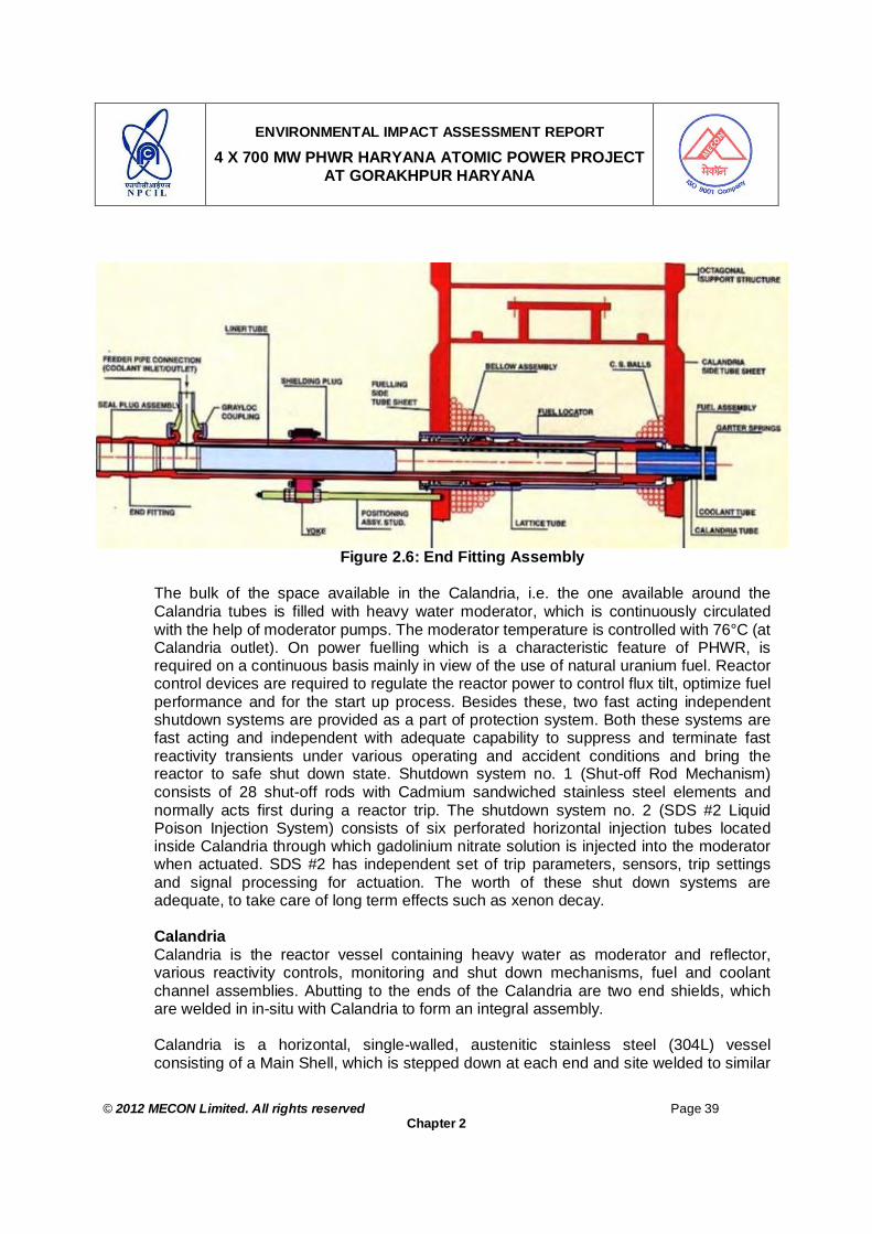
ENVIRONMENTAL IMPACT ASSESSMENT REPORT
4 X 700 MW PHWR HARYANA ATOMIC POWER PROJECT AT GORAKHPUR HARYANA
© 2012 MECON Limited. All rights reserved Page 39
Chapter 2
Figure 2.6: End Fitting Assembly The bulk of the space available in the Calandria, i.e. the one available around the Calandria tubes is filled with heavy water moderator, which is continuously circulated with the help of moderator pumps. The moderator temperature is controlled with 76°C (at Calandria outlet). On power fuelling which is a characteristic feature of PHWR, is required on a continuous basis mainly in view of the use of natural uranium fuel. Reactor control devices are required to regulate the reactor power to control flux tilt, optimize fuel performance and for the start up process. Besides these, two fast acting independent shutdown systems are provided as a part of protection system. Both these systems are fast acting and independent with adequate capability to suppress and terminate fast reactivity transients under various operating and accident conditions and bring the reactor to safe shut down state. Shutdown system no. 1 (Shut-off Rod Mechanism) consists of 28 shut-off rods with Cadmium sandwiched stainless steel elements and normally acts first during a reactor trip. The shutdown system no. 2 (SDS #2 Liquid Poison Injection System) consists of six perforated horizontal injection tubes located inside Calandria through which gadolinium nitrate solution is injected into the moderator when actuated. SDS #2 has independent set of trip parameters, sensors, trip settings and signal processing for actuation. The worth of these shut down systems are adequate, to take care of long term effects such as xenon decay.
Calandria Calandria is the reactor vessel containing heavy water as moderator and reflector, various reactivity controls, monitoring and shut down mechanisms, fuel and coolant channel assemblies. Abutting to the ends of the Calandria are two end shields, which are welded in in-situ with Calandria to form an integral assembly. Calandria is a horizontal, single-walled, austenitic stainless steel (304L) vessel consisting of a Main Shell, which is stepped down at each end and site welded to similar

ENVIRONMENTAL IMPACT ASSESSMENT REPORT
4 X 700 MW PHWR HARYANA ATOMIC POWER PROJECT AT GORAKHPUR HARYANA
© 2012 MECON Limited. All rights reserved Page 40
Chapter 2
extensions of End shields on either side. The stepped down shells, called `Small Shells’, are joined to the Main Shell by means of flexible Annual Plates, thereby forming vertical annular sections, which deflect to allow for the differential thermal expansion of stainless steel shell with respect to the Calandria tubes and the concrete vault walls. The location of the annular plates is selected to give an optimum reduction in inventory of expensive heavy water in the low flux regions of the vessel and to provide adequate space for welding of Calandria to the End shields at site. Sectional view of Calandria is given in Fig. 2.7. There are 392 coolant tubes and 392 Calandria tubes arranged in a square lattice of 286 mm pitch. The Zircaloy-4 Calandria tubes are rolled into the end shields. Four annular spacers (garter springs) have been provided in each coolant channel to maintain appropriate gap between the Calandria tube and coolant tube, carrying fuel and coolant. The Calandria shell has 85 nozzles on top and another 13 on west side for housing mechanisms for reactor control and monitoring. Corresponding to each reactivity mechanism nozzle, housing is provided at bottom of the vessel to locate and support different devices. Four numbers of 500 mm NB over pressure relief lines are also provided on the top of Calandria. These lines terminate in the pump room and are provided with rupture-discs at the ends. The rupture discs are of reverse buckling type having a set pressure of 1.4 kg/cm2. 12 numbers of 150 mm NB moderator inlet connections (6 nos. on either side) are welded to the main shell near its horizontal centerline plane. At each moderator inlet location, an inlet diffuser of gradually increasing rectangular cross-section is provided. These diffusers are oriented in such a manner that they discharge the incoming heavy water all along the curved surface towards the top of the shell with low velocity and without impinging directly on any Calandria tube. The lower end of the diffuser is welded to the stainless steel nozzles already welded to the Calandria main shell. Four moderator outlet nozzles of 250 mm NB are provided at the bottom of the main shell at locations slightly away from the vertical axial plane.

ENVIRONMENTAL IMPACT ASSESSMENT REPORT
4 X 700 MW PHWR HARYANA ATOMIC POWER PROJECT AT GORAKHPUR HARYANA
© 2012 MECON Limited. All rights reserved Page 41
Chapter 2
Figure 2.7: Sectional View of Calandria
End Shields The end-shields provide shielding on the reactor ends to reduce the dose rate in fuelling machine vaults to an acceptable level, support and locate coolant channel assemblies and provide integral support to reactor assembly. The stainless steel end-shields are filled with 10 mm dia. spherical carbon steel balls and light water in 57:43 volumetric ratios, which provides adequate shielding properties. For cooling, the End shield water is circulated through external cooling circuit.
The support structure for end shield consists of a cylindrical shell called as outer shell of 8088 mm ID which is concentric with the main shell and two end flanges welded to it to form an `H’ section. The outer edges of end flanges are octagonal in shape. The inner edges of end flanges are machined circular and welded to the extensions of fuelling side tube sheet and Calandria side tube sheet. The portions of the end flanges and extensions of tube sheets between outer shell and main shell are machine to a thickness of 24 mm to serve as flexible diaphragms for accommodating the radial thermal expansion of the End shield and longitudinal thermal expansion of Calandria tubes (these are rolled in the Calandria side tube sheets of both end shields). The diaphragm plates also transfer the entire weight of the reactor assembly to the vault concrete.
The space enclosed by the two diaphragm plates, the main shell and outer shell is filled with light water. The weld between flange plates and extensions of the fuelling machine side tube sheet and Calandria side tube sheet is located in a region of diaphragm which is subjected to the minimum stress. Three numbers of annular shielding plates are provided adjacent to diaphragm plate on fuelling machine side to enhance shielding capacity.

ENVIRONMENTAL IMPACT ASSESSMENT REPORT
4 X 700 MW PHWR HARYANA ATOMIC POWER PROJECT AT GORAKHPUR HARYANA
© 2012 MECON Limited. All rights reserved Page 42
Chapter 2
2.12.4 Reactivity Devices
Reactivity devices include those devices which are required for reactor regulation, reactor shutdown and flux monitoring. Reactivity devices are provided for following functions :
a. To regulate zonal and bulk reactor power b. To shape core flux distribution to maximize the power output c. To provide xenon poison override time after reactor trip d. To raise or lower reactor power to desired level i.e. power maneuvering including set
back and step back. e. To rapidly shutdown the reactor and keep it sub-critical for prolonged period to time
through one of two diverse, independent systems. f. To measure reactor power over a wide range from shutdown to 150% full power g. To provide reactivity shim during extended fuelling machine outages
Liquid Zone Control System, Adjuster Rod Mechanism, Control Rod Mechanism, Shut-off Rod Mechanism and Vertical Flux Units are located vertically inside the reactor core while Liquid Poison Injection System and Horizontal Flux Units are located horizontally. The ionization chamber housing assemblies are located horizontally outside Calandria in the east and west walls of Calandria vault.
Mechanical and process design details of Shutdown system no. 1 and no. 2 are covered in Section 5. Details of other reactivity devices are brought out in the following sections:
Liquid Zone Control System Liquid Zone Control System provides zonal and bulk power control. Zonal power control is required due to large size of reactor core and consequent neutronic decoupling. There are six Liquid Zone Control Units having 14 Zone Control Compartments (ZCCs). Water, as neutron absorber is maintained in the ZCCs and the level of water in the ZCCs is varied to get a bi-directional change in reactivity. Level of water in a ZCC is varied by varying the inlet flow using a control valve and keeping the outlet flow constant. The outlet flow is maintained constant by controlling the differential pressure between the ZCCs and the Delay Tank (where the water outlet are collected) to a constant valve. Helium is used as cover gas to the water. Water is circulated through Heat exchanger and Ion Exchange Column for heat removal and chemical cleaning respectively. Helium over-gas is also kept under circulation to remove products of radiolysis and to pass through recombination unit. Helium is bubbled into the ZCCs and is used for measurement of water levels in the ZCCs. Water and helium pressures in the circuits are maintained by pump(s) and compressor(s) respectively.
Adjuster Rod Mechanism The system consists of seventeen adjuster rods utilizing tubular stainless steel or cobalt absorbers. At each of the seventeen locations, adjuster rod mechanism consists of adjuster rod assembly, guide tube assembly, locator assembly, standpipe-thimble assembly, shield plug, push tube cum magnet assembly, drive mechanism and the supporting, sealing and shielding arrangements. The adjuster rod consists of a vertical tubular stainless steel element and a zircaloy rope attachment at its top. The upper end of SS wire rope is attached to and wound on a sheave inside the drive mechanism. An electric motor, through a set of gears drives the rod up or down inside a guide tube

ENVIRONMENTAL IMPACT ASSESSMENT REPORT
4 X 700 MW PHWR HARYANA ATOMIC POWER PROJECT AT GORAKHPUR HARYANA
© 2012 MECON Limited. All rights reserved Page 43
Chapter 2
assembly. While not in motion, the rod is held in position by the self-locking feature of drive mechanism provided by proper design of worm gear unit. Adjuster rods remain within the reactor core during normal operation. For regulating purposes, the adjuster rods are driven out and driven into the core by Reactor Regulating System (RRS), as required.
Control Rod Mechanism The system consists of four control rods utilising cadmium absorber elements. At each of the four locations, the system consists of control rod assembly, guide tube assembly, guide tube locator assembly, stand-pipe-thimble assembly, shield plug cum push tube assembly, drive mechanism and the supporting, sealing and shielding arrangements. The control rod consists of a vertical tubular cadmium absorber sandwiched between stainless steel tubes, a rope attachment at its top and an orifice at bottom. The upper end of SS wire rope holding the CR is attached to and wound on a sheave inside the drive mechanism. The rod is held in parked position with help of self locking feature provided by design in worm gear unit of drive mechanism. An electric motor, through gear drive and electromagnetic clutch, drives the rod up or down inside a guide tube assembly. On de-energizing the electromagnetic clutch, the rod falls under gravity into the guide tube assembly inside reactor core.
For the purposes of regulating functions, the control rods are driven into and out of the core by Reactor Regulating System (RRS), as required. During a reactor set back, one or both banks of control rods are driven partially or fully into the reactor core by RRS. During reactor trip both banks of control rods are also dropped into the core along with shut-off rods of shutdown system no. 1 (SDS #1).
In – Core Flux Units Self-Powered Neutron Detectors (SPNDs) are used for in-core flux measurement. There are SPNDs belonging to Reactor Regulating System (RRS), known as Zone Control Detectors (ZCDs), SPNDs belonging to Reactor Protection System 1 & 2 (RPS), know as Regional Over Power Protection System ROPPS) Detectors and SPNDs belonging to Flux Mapping System (FMS), known as Flux Mapping Detectors. In addition to these SPNDs, there are Traveling In-Core Probes (TIPs) and in-core Start Up Counters (SUCs). All these are housed in tubular in-core Carrier Tuber Assemblies (CTAs). These Carrier Tube Assemblies along with related components are known as Vertical and Horizontal Flux Units (VFU, HFU) depending on whether they are oriented vertically or horizontally in the core. Vertical Flux Units There are 26 Vertical flux units located vertically inside the Calandria. The VFUs houses: ZCDs of RRS ROPPS Detectors of RPS # 1, Flux Mapping Detectors, Vertical Travelling In-core Probes (TIPs) and In-core Start up counters (SUCs).

ENVIRONMENTAL IMPACT ASSESSMENT REPORT
4 X 700 MW PHWR HARYANA ATOMIC POWER PROJECT AT GORAKHPUR HARYANA
© 2012 MECON Limited. All rights reserved Page 44
Chapter 2
Typically, a VFU is attached to Calandria shell, at the bottom, by means of a locator assembly and extends up to the top of Calandria vault top-hatch beam. Beyond the Calandria nozzle, standpipe-thimble assembly, which is the extension of Calandria, surrounds the VFU. The SPNDs are houses in Zircaloy Carrier Tube Assembly. Soft cables are run from cable connectors mounted on or near the terminal box at the top of the assembly, beyond the hatch beam area.
Horizontal Flux Units The function of horizontal flux units is to house SPNDs for Reactor Protection System (RPS) # 2, known as ROPPS Detectors, at the required locations in the reactor core.
There are 9 horizontal flux units, laid normal to both Calandria tubes and vertical reactivity device assemblies. A HFU, typically, is attached to the Calandria shell by means of locator assembly at the east side and extends beyond Calandria up to the outside of Calandria vault west wall. The thimble assembly, which is the extension of Calandria, surrounds the HFU in the region beyond Calandria. The HFU surrounded by the thimble assembly passes through an Embedded Part (EP) in the Calandria vault west wall. The SPNDs are housed in Carrier Tube Assembly. The Mineral Insulated (MI) cables of the SPNDs are terminated on or near the terminal box at the west end of the HFU, just outside the vault wall. Other components include shielding structure, sealing bellows assemblies, tensioning arrangement, freeze jacket etc.
Ionization Chamber Housing Assemblies The requirement of thermal neutron flux measurement from the source level of about 10-14 Full Power (FP) to 150% FP is met by employing in-core and out of core neutron detectors. The out of core neutron detectors are of two types viz. boron coated un-compensated proportional counter (start-up counter) and boron coated un-compensated ionization chambers. The out of core detectors are housed in ionization chamber housing assemblies located in the east and west walls of Calandria vault.
For housing the boron coated start-up counters and the ionization chambers (known as detectors) located outside the core, six ionization chamber housing assemblies, three each on the Calandria vault east wall and west wall are provided. Each ionization chamber housing assembly on the east wall houses three ionization chamber cylinders, one each belongs to Reactor Regulating System (RRS), Reactor Protection System No. 1 (RPS # 1). Each ionization chamber housing assembly on the west wall houses one ionization chamber cylinder belonging to Reactor Protection system No. 2 (RPS # 2) and the start up counter.
A typical ionization chamber housing assembly consists of a housing pipe assembly located in an Embedded Part (EP) in the Calandria vault wall. The assembly houses 3 tubes, known as guide pipes. These pipes house ionization chamber cylinder or start-up counters along with shielding and other accessories. The third pipe is provided as spare. The guide pipes are arranged in a triangular pitch and the space surrounding the pipes within the housing assembly is filled with heavy concrete. The Calandria end of the housing assembly is provided with lead shielding to achieve discrimination against gamma radiation. The housing assembly is supported from the inside face of the Calandria vault wall. The Calandria vault water is sealed by a plate welded between the housing assembly and the EP flange at the inside face of the Calandria vault wall.
ENVIRONMENTAL IMPACT ASSESSMENT REPORT
4 X 700 MW PHWR HARYANA ATOMIC POWER PROJECT AT GORAKHPUR HARYANA
© 2012 MECON Limited. All rights reserved Page 45
Chapter 2
2.12.5 Moderator Liquid Poison Addition System
Moderator Liquid Poison Addition System (MLPAS) is provided to augment the reactivity worth of control rods, which are controlled by reactor regulating system. The system also facilitates manual addition of a pre-determined limited quantity of poison into the moderator, based on the status of reactor core and stipulated conditions of start up after a poison out. The system is used to control the reactivity of the core by adding soluble chemicals with large neutron capture cross-sections in to heavy water moderator. Boron as boric anhydride (B2O3) and Gadolinium as gadolinium nitrate hexa-hydrate (Gd (NO3)3.6 H2O) are the chemicals used. The need of this system arises due to following considerations :
1. Control rods provide capability to handle setback to low power level to the reactor
regulating system. To ensure that this capability is always available, control rods are normally parked in the fully `OUT’ position. If due to any unanticipated reactivity change during power operation, corrective action is taken by the regulating system, such that reactor operates with control rods partially `IN’. Additional negative reactivity must be made available to regain the full worth of control rods. Adding small shots of poison into the moderator through MLPAS does this. The shots are repeated at regular intervals, till the causative factor is removed.
2. Any uninterrupted reactivity disturbances at a time, when the worth of control rods is not available, will result in bulk power increasing beyond demand power. MLPAS will provide a means for limiting the actual power under such conditions depending upon the reactor power and effective power error.
3. To provide a means for manual addition of negative reactivity to the core, such as required during xenon burn up, when the reactor is brought to full power, just after the poison out period.
The moderator Liquid Poison Addition System works on ejector principle using moderator circulation as the motive force. Depending upon system requirement, either boric acid or gadolinium nitrate is sucked from respective tanks.
2.12.6 Primary Heat Transport System
The Primary heat transport (PHT) system transports heat produced in the rector core to steam generators to generate steam, which is fed to the turbine. The transport medium is pressurised Heavy Water.
PHT main circuit is arranged in two identical loops. The core is divided vertically into two halves, to form two loops. Partial boiling is allowed in the channels to the extent to obtaining a nominal quality up to 4% at reactor outlet header (ROH). The two reactor outlet headers of both the loops are interconnected to avoid flow instability. Diagrammatic Representation of PHT system is given in Fig. 2.8.

ENVIRONMENTAL IMPACT ASSESSMENT REPORT
4 X 700 MW PHWR HARYANA ATOMIC POWER PROJECT AT GORAKHPUR HARYANA
© 2012 MECON Limited. All rights reserved Page 46
Chapter 2
Figure 2.8: Diagrammatic Representation of PHT System
Main Functions and Objectives The functional requirements of the system are : 1. To transport 2166 MW of thermal power from reactor core to steam generators (4
SGs) during normal operation. 2. To ensure core cooling during all operational states and accident conditions. 3. To prevent the failure or limit the consequence of failure of a component or structure
whose failure would cause impairment of a safety function. 4. To maintain cool-able geometry of the core during all operational states and
postulated accident conditions. It also acts as a barrier against release of radioactivity from the core. The heat transport system includes following sub-systems :
1. Pressuriser feed and bleed, for pressure and inventory control. 2. Relief system for over pressure protection. 3. Fuelling Machine heavy water supply system to supply high pressure heavy water to
the fuelling machines. 4. Purification system for maintaining desired water chemistry and removal of corrosion
products. 5. Shutdown cooling system for removal of decay heat. 6. Emergency core cooling system (ECCS) to maintain core cooling following a loss of
coolant accident (LOCA). 7. Inventory addition and recovery system (IARS) to maintain PHT inventory in the
event of a small leak, which is within the capability of primary pressurizing pump.

ENVIRONMENTAL IMPACT ASSESSMENT REPORT
4 X 700 MW PHWR HARYANA ATOMIC POWER PROJECT AT GORAKHPUR HARYANA
© 2012 MECON Limited. All rights reserved Page 47
Chapter 2
8. Leakage collection system to collect, contain and transfer the collected heavy water and to provide venting and draining facility to the equipment.
9. Service system to facilitate filling and draining of steam generator – primary coolant pump loop and header level control.
10. Sampling system for monitoring the system chemistry. 11. Passive Decay Heat removal system (PDHRS) for decay heat removal during station
blackout condition. Passive Decay Heat Removal System (PDHRS) Primary function of the Passive Decay Heat Removal System (PDHRS) is to ensure continued availability and recirculation of the inventory on the secondary side of the Steam Generators in the event of class IV failure simultaneous with non-availability of Auxiliary Boiler Feed Pumps (ABFPs) or Station blackout and in the process ensure continued removal of decay heat from the core.
2.12.7 Moderator System
The purpose of heavy water moderator is to maintain criticality in the reactor core by slowing down the high-energy neutrons to a lower energy level where their probability for fission capture is higher.
Heavy water used as moderator inside the Calandria gets heated up due to neutron moderation and capture, attenuation of gamma radiation as well as due to transfer of heat from other reactor components in contact. The primary function of moderator circulation system is to maintain equilibrium moderator temperature in the core, by providing sufficient cooling to remove about 123 MW to heat generated in moderator at full power. 6 x 20% canned motor pumps are provided for moderator circulation.
The system supplies heavy water to adjuster rod mechanisms for cooling of the adjuster rods. Reactivity control by chemical shimming is done using boron / gadolinium nitrate as liquid poison in moderator. The system supplies heavy water, as power water, to Moderator Liquid Poison Addition System (MLPAS).
Presence of ionic impurities in moderator increases transport and buildup of radioactivity in the circuit as well as increases rate of radio-lytic decomposition of heavy water within Calandria. In view of this, a portion of the moderator flow is continuously circulated through ion exchange columns. Separate ion exchange column are provided for removal of boron or gadolinium nitrate poison from moderator, which are added through MLPAS or Shut Down System #2.
Heavy water in the Calandria also functions as a heat sink in the unlikely event of Loss of Coolant Accident (LOCA) coincident with the failure of Emergency Core Cooling System (ECCS). Moderator level in Calandria is maintained at 100% full tank (FT) level at full power. Moderator level in Calandria varies from cold shutdown state to full power, due to variation in temperature. The extent of variation could be 95.7% FT level under cold
ENVIRONMENTAL IMPACT ASSESSMENT REPORT
4 X 700 MW PHWR HARYANA ATOMIC POWER PROJECT AT GORAKHPUR HARYANA
© 2012 MECON Limited. All rights reserved Page 48
Chapter 2
shutdown condition. In addition, there is change in level due to insertion or withdrawal of Shut off Rods, Control Rods and Adjuster Rods. The level variation affects interface between the Calandria heavy water and the gadolinium nitrate poison in Shut Down System #2 leading to migration of poison towards Calandria. To minimize the level variation, a head tank has been provided.
Moderator system is designed to remove about 123 MW heat. However, each heat exchanger is rated at 63 MW to provide margin of 3 MW. The moderator temperature has been optimized based on the following considerations.
1. Heat exchanger size and heavy-water hold-up. 2. Thermal stresses in Calandria and end shield 3. To have enough sub-cooling to act as heat sink in the event of failure of ECCS
following LOCA. Considering these aspects, normal operating temperature of moderator at Calandria outlet has been selected, as 76°C and maximum temperature is restricted to 83°C by providing reactor setback.
Full tank level in Calandria during normal operation is chosen on the basis of following considerations :
1. If level is kept less than 100%, these could be more ripples on the surface which can
cause more vibration of the various guide tubes and flux monitoring tubes inside Calandria. Surface ripples and consequent vibration will be much less if Calandria is 100% full, because, open surface area is only in the four 500 mm O.D.OPRD lines.
2. With level less than 100%, there will be sloshing of D2O in Calandria during and earthquake.
3. With moderator level at 100%, the release of deuterium is low because of less exposed surface area.
4. With moderator level at 100%, flux distortion will be less Moderator Cover Gas System To accommodate volumetric changes in moderator due to temperature variations and injection of liquid poison on actuation of SDS #2 and to control system pressure, a gas space is provided in the top portion of Calandria, above the free surface of the moderator in the overpressure relief lines. This space is filled with helium, which is an inert gas that does not react chemically with heavy water. Helium is also stable under nuclear radiation.
In Calandria, during reactor operation, high neutron flux and the gamma radiation cause radiolysis of the moderator. The moderator breaks down into its constituent elements of deuterium and oxygen. These dissolved gases are released into the helium gas space where they collect and may eventually reach unacceptable concentrations. To avoid this, the helium is continuously circulated through recombination units.

ENVIRONMENTAL IMPACT ASSESSMENT REPORT
4 X 700 MW PHWR HARYANA ATOMIC POWER PROJECT AT GORAKHPUR HARYANA
© 2012 MECON Limited. All rights reserved Page 49
Chapter 2
The main cover gas circulation system consists of Calandria, four over-pressure relief pipes, standpipes of Reactivity Devices, helium blowers, Recombination Units and necessary valves and piping.
2.12.8 End Shield and Calandria Vault Cooling Systems
The End Shield cooling system serves to remove nuclear heat generated in the End Shield and heat transferred from the primary coolant across insulating gaps between end fittings and lattice tubes and across support bearings of coolant channels.
The criteria for design are : 1. To limit Calandria side tube sheet temperature to levels acceptable from the point of
view of radial expansion. 2. To obtain a fairly uniform temperature distribution in the end shields structure and
minimise thermal stresses. 3. To maintain compatible water chemistry with the end shield components. Water in the end shields also provides neutron shielding.
The minimum heat to be removed from each end shield is about 2450 kW and the heat transferred from primary system is about 1130 kW. Water chemistry compatible with the end shield structure is maintained and a purification loop is incorporated for removal of impurities from the circuit.
The Calandria vault cooling system serves to remove the heat generated in the Calandria vault water. Calandria vessel is submerged inside a pool of water in the Calandria vault. The function of water is two-fold, firstly to serve as thermal shield around the Calandria and secondly to cool the vault walls which serve as biological shield. The radiation heat generated in the light water and the vault walls as well as the heat from the Calandria shell is transferred to the Calandria vault water. The vault water is recirculated through the Calandria vault cooling system by pumps and is cooled by heat exchangers. The average temperature of vault water is about 52°C and the vault concrete temperature is about 60°C. The acceptable maximum concrete temperature for continuous operation is 65°C. The heat to be removed from the vault water is about 4505 kW and system is designed for 5000 kW.
The End Shield and Calandria vault cooling systems reject the heat to the Active Process Water System. The system is classified as safety class 3.
2.12.9 CO2 Annulus Gas System
CO2 is circulated through the annuli between coolant tubes and Calandria tubes. Monitoring of moisture content of CO2 is done to assess the coolant tube integrity. High purity CO2 is circulated through all the annuli continuously at a rate of 30 Nm3/hr. The maximum permissible dew point of makeup CO2 is (-) 20°C. Provision is made for on-line dew point monitoring. Besides pressure rise monitoring in the circuit is also annunciated. Annunciation is given if the dew point of circulating CO2 rises to (-) 5°C, which indicates

ENVIRONMENTAL IMPACT ASSESSMENT REPORT
4 X 700 MW PHWR HARYANA ATOMIC POWER PROJECT AT GORAKHPUR HARYANA
© 2012 MECON Limited. All rights reserved Page 50
Chapter 2
leak from one or more of the coolant tubes. Manual shutdown of the reactor is initiated. The annulus gas tubes from individual channels are grouped into several strings and these are grouped in sub groups and a process of elimination identifies the sub group containing the leaky tube, isolating one group at a time. Design pressure of annulus gas system is 1.75 kg / cm2.
2.12.10 Secondary Systems
The main steam supply system has been designed with the following objectives. 1. To act as a heat sink for the reactor coolant. 2. To transport steam from the steam generator outlet nozzles to the HP turbine reliably
and economically for power generation. 3. To supply steam to auxiliaries forming part of the turbine cycle and to other
miscellaneous needs. 4. To maintain the integrity of the pressure boundary of fluid system under normal
operation and anticipated operational occurrences. 5. To minimise poison outages of the reactor due to turbine faults, certain grid faults
and certain primary side conditions.
2.12.11 Fuel Handling and Control System
Two Fuelling Machines (FM) operating in conjunction, one at each end of Reactor, carry out on-power refueling. Fresh fuel bundles are inserted at one end while the other machine at the other end receives the spent fuel bundles. Bi-directional refueling in adjacent channels is adopted (in the direction of flow) to smoothen axial flux pattern. Spent Fuel Bundles received in the Fuelling Machine are transferred to the Fuel Transfer Equipment i.e. mobile Transfer Machine and subsequently transferred from mobile Transfer Machine to the Tray loading Bay (TLB) located in the Spent Fuel Building. The spent fuel bundles are stored under water in trays in storage Bay for sufficient period before they are transported to a reprocessing plant.
Normally eight bundles refueling is adopted to optimize utilizations of Fuel and operation of Fuelling Machines. In an equilibrium core it would add reactivity of about 0.3 mK on an average, for each channel in a refueling operation which normally takes about 4 hours. Total number of channels to be refueled in a day is determined from the point of view of addition of reactivity required for sustained operation.
Spent Fuel Bundles, while in FM Head, are cooled by re-circulating heavy water whereas in mobile Transfer Machine cooling is done by re-circulating light water. From the Fuelling Machine, only one pair of bundles at a time is transferred to light water environment in the mobile Transfer Machine. This dry transfer operation normally lasts about 4 minutes. During abnormal condition, if the dry transfer operation is not completed within 5.72 minutes, cooling by water spray / filling is provided. After transfer to light water environment, submerging the bundles in light water ensures cooling. Thereafter the bundles are transferred to Tray loading bay and then to Storage Bay by underwater operations only. Storage Bay water is cooled by re-circulation through heat exchangers.

ENVIRONMENTAL IMPACT ASSESSMENT REPORT
4 X 700 MW PHWR HARYANA ATOMIC POWER PROJECT AT GORAKHPUR HARYANA
© 2012 MECON Limited. All rights reserved Page 51
Chapter 2
The Spent Fuel Storage Bay and Tray Loading Bay are lined with stainless steel to provide a primary leak tight barrier. The liner has provision to collect any leakage of bay water. Spent fuel bundles are loaded in the trays at tray loading bay.
The tray loading bay also incorporates inspection facility for detection of ruptured spent fuel bundles. The storage bay has capacity to store spent fuel discharged for about 10 reactor years in addition to provision for unloading of one core in case of emergency. Provision also exists to ship spent fuel to either reprocessing plant or any other consolidated interim storage facility.
A large number and variety of devices such as Pumps, Valves, Hydraulic Cylinders, motors etc. are used in the Fuel Handling and Control System. The design of these devices is based on following considerations : 1. Redundancy is provided to ensure cooling of Spent Fuel bundles after it is taken out
of the core. 2. Fail-safe devices and auto initiated back up actions are employed to the extent
feasible. 3. The maximum risk is limited to damage of only four pairs of bundles, which are also
always contained in a vessel. The Fuel Handing Control System enables the control of Fuelling systems comprising Fuelling machines, Fuel transfer, Vault and Service area doors and Roll-on shield. The control system is computerized, which gives sequential commands to the two fuelling machines to enable automatic refueling of reactor at any selected coolant channel. The system also gives sequential commands to Fuel Transfer Tray Loading Bay. Both Software and hardware interlocks are provided to ensure that the commands issued to the system result in safe operation. The system provides for safe manual mode operations during conditions when the control computer is not available. The subsystems, which are not computer controlled, are designed to be operable only in manual mode.
2.12.12 Instrumentation and Control (I&C)
The Instrumentation & Control (I&C) systems in 700 MWe include a variety of equipment intended to perform display, monitoring, control, protection & safety functions. The concepts presented form the basis for the system design and development. General guidelines followed are :
1. Electrical transmission of signals is preferred to pneumatic, because of better
amenability to further processing in addition to inherent fast response etc.
2. Equipment free from ageing, wear and not needing routine and preventive maintenance are preferred. Microprocessor-based systems, solid-state semi-conductor devices are preferred over mechanical systems having moving parts. The computerization of control algorithms and operator interface are provided wherever required.

ENVIRONMENTAL IMPACT ASSESSMENT REPORT
4 X 700 MW PHWR HARYANA ATOMIC POWER PROJECT AT GORAKHPUR HARYANA
© 2012 MECON Limited. All rights reserved Page 52
Chapter 2
3. The component / equipment quality requirements are covered in the individual specification / requirement sheets. The quality of equipment is met by selection of components (e.g. grade of components / screening), routine testing as per Indian / International standards environmental testing as per Indian / International standards and rigorous functional testing. For computerized system, software verification and validation review / audit procedure based on AERB-SW-D25 guide is followed. The quality requirements commensurate with the safety class. Principles of redundancy, diversity, fall-safe, testability and maintainability are extensively employed to maximize availability while ensuring safety. Physical separation of redundant channels is provided.
4. Modular construction of I&C systems is followed to minimise repair time.
5. For all safety systems Triplicated sensors and logic based on majority coincidence (2 out of 3) principles is used. On line testing facility for protection channel is provided.
6. Independence between control & data communication is maintained for safety
systems.
7. The sensors and associated electronics for each channel is physically separate and follows diversified cable routing.
8. Instrumentation & Controls of the shutdown system #1, Emergency core cooling system and Decay heat removal system are located in Control Equipment Room (CER) / Main Control Room (MCR). I&C of Shut-down system #2 & Containment Isolation are located in Reactor Auxiliary Building. I&C of fire water, decay heat removal under Emergency conditions is located in Fire water pump house.
9. The overall I&C design is such that all the safety functions are normally achievable from MCR. In case MCR is inhabitable then all the safety functions can be carried out from Back-up Control room (BCR) and Back-up control points.
10. In the control loops for Neutronic signals and for some important signals (e.g. PHT pressure) traditional approach of Triplicated sensors is maintained. The Triplicated process variable signals are processed for rationality and median signal is used for control. The microprocessor-based systems with hot standby configuration are used as controllers for these loops. When duplicate sensors are used, average signal of sensors is used for further processing (e.g. level transmitters of LZC, rod position signals etc.). In case of failure of one sensor, other sensor signal is used. Any gray failure is detected by monitoring deviation among sensors of same parameter and is indicated. The operator will identify the failed sensor by inference from other parameters, local gauges etc. In case of gray failure, the system selects the conservative signal, wherever applicable. For non-critical systems, control, monitoring and indication functions are achieved by single sensor (e.g. air compressor control, leakage collection system, monitoring of hydrogen concentration in cover gas etc.). Due credit is taken for manual sampling / monitoring facilities.

ENVIRONMENTAL IMPACT ASSESSMENT REPORT
4 X 700 MW PHWR HARYANA ATOMIC POWER PROJECT AT GORAKHPUR HARYANA
© 2012 MECON Limited. All rights reserved Page 53
Chapter 2
11. Instrument air, wherever required meets the availability requirements of I&C systems, Independence and functional isolation is incorporated. Local instrument air accumulators are provided wherever operation of valve is required even after instrument air supply failure.
12. A high degree of automation is aimed at to eliminate human error affecting availability / reliability. However, some systems, e.g. D2O leak detection, failed-fuel detection etc. will need operator surveillance and action for remedial measures.
13. Simplicity in design, operator acceptance, obsolescence, current trend in technology are given due consideration.
Main Control Centre The control of power plant is based on the philosophy of a centralized control room sufficiently instrumented to provide adequate information to the operator regarding the status of the plant and to enable safe and efficient control of the plant. Main Control Room (MCR) is located in the Control Building at 111 m floor. A common control room is provided for two units. Fig. 2.9 indicates pictorial view of main control room panels for 700 MWe Plant. VDU based soft controls are provided for all IB, IC & NINS systems. Conventional controls, indication and displays are provided for safety critical applications and for some safety related systems hard-wired backup is also provided. These controls, indications and displays are provided on main control panels and operator consoles. Number of large video screens is provided for displaying the plant information. The main control room panels and operator consoles of each unit are arranged in “Horse-shoe” arrangement. Arrangement of the systems on the main control room panels is done on the basis of the functional requirements. Window annunciations are provided on top portion of the panels. Window annunciations call for immediate operator attention and are very important under all plant conditions. With a view to present the desired information to the operator in an overall compact fashion, a computer based operator information system is provided. Operator Information Concoles (OIC) with VDU & Keyboard of various computerized systems are provided in the MCR. OICs are designed for sitting operation. On these VDUs operator can get information on various systems of the plant. One computer room is provided for each unit. In this room, computers and peripherals of computerized systems are located. Only very essential controls and indications are provided on MCR panels. However, to supplement these devices many other type of components / requirements are required. These are mounted on auxiliary panels, which are located in Control Equipment Room (CER). CER is located at the same floor are MCR. Physical separation of channel equipment with total fire barriers is achieved by providing 3 separate rooms for each unit for triplicated channels Power supply for illumination of control room of unit-3 is independent of unit-4. Similarly, independent air-conditioning systems are provided for

ENVIRONMENTAL IMPACT ASSESSMENT REPORT
4 X 700 MW PHWR HARYANA ATOMIC POWER PROJECT AT GORAKHPUR HARYANA
© 2012 MECON Limited. All rights reserved Page 54
Chapter 2
control rooms of both the units. In MCR, emergency fresh air ventilation system is provided. During radioactivity release, air is made to pass through charcoal and HEPA filters before being supplied to Control room. Control and Instrumentation cables of redundant systems are segregated as per IEEE 384. Non-safety related cables are also segregated from the safety related cables as per IEEE 384.
Fig. 2.9 : Pictorial view of main control room panels for 700 MWe Plant

ENVIRONMENTAL IMPACT ASSESSMENT REPORT
4 X 700 MW PHWR HARYANA ATOMIC POWER PROJECT AT GORAKHPUR HARYANA
© 2012 MECON Limited. All rights reserved Page 55
Chapter 2
Back-Up Control Room Back-up Control Room (BCR) is provided in nuclear building, diametrically opposite to MCR, so that some of the essential functions of the MCR relating to monitoring of the important parameters, controls relating to reactor safe shutdown can be carried out in the event the main control room becomes inhabitable. For decay heat removal and for monitoring the PHT pressure, two nos. of back up control points are provided in Station Auxiliary Buildings (SAB) for safety related group Y and Z loads.
Separate sensors, power supplies & cables are provided for most of the back up control room indications. A VDU is also provided to give the total information of the plant.
Control and Instrumentation cables of redundant systems of back up control room are also segregated as per IEEE 384.
Radiation Monitoring System Radiation Monitoring System helps to control exposure of the plant personnel / public and gives advance indication of malfunctioning of Reactor Systems. There are about 60 Area Radiation Monitors located all over the plant area. These units provide information pertaining to radiation fields within the plant and also provide alarms when the field exceeds the alarm limits. 6 Nos. of environmental monitors are located within the plant exclusion area. Signals from these units are transmitted to control room for display and annunciation. The reactor-building is isolated when the release rate exceeds the set limits. The triplicate ventilation duct monitors are provided to monitor primary containment exhaust activity and keep 2/3 signals for Reactor building isolation when release rate exceeds. A set of stack monitoring instruments is also provided in the stack monitoring room to measure the discharge activity.
Release rate display and alarms are provided in the control room for Iodine, particulate gross gamma and tritium activity releases. Inter-zonal contamination monitors are provided to help preventing spread of contamination in case local contamination occurs.
2.12.13 Electrical System
Various auxiliaries (i.e. various electrical loads) of the power station are provided with power supply from Off-site and On-site sources. The offsite power supply is derived from 400 kV and 220 kV switchyards. The 400 kv system is primarally used for evacuating te power generated by HAPP. The switchyard structures and equipment are designated as codal category.
Start up transformers (SUTs) are connected to 220 kV switchyard. These are used as one of the source of station auxiliary power. Turbo-Generators (TGs) are connected to the LV side of Generator Transformers (GTs) and serve as another source off-side power. When a shutdown has to be taken up on TG, it is isolated by means of generator circuit breaker (GCB) and Unit Transformer (UTs) will continue to be available. The number of transmission lines connected to the switchyard is such that the requirements of AERB safety guide AERB / SG / D11 are met. The station auxiliary power supply system is classified into four classes depending on the required availability. These are :

ENVIRONMENTAL IMPACT ASSESSMENT REPORT
4 X 700 MW PHWR HARYANA ATOMIC POWER PROJECT AT GORAKHPUR HARYANA
© 2012 MECON Limited. All rights reserved Page 56
Chapter 2
Class I system : 220 V DC control power supplies Class II system : 415 V AC 3 phase system Class III system : 6.6 kV and 415 V AC 3 phase systems Class IV system : 6.6 kV and 415 V AC 3 phase systems
Class I power supply system (based on batteries) is used for the supply of control power for circuit breakers and controls such as control of DG sets, turbo-generator, etc. The DC supply system is normally supplied from Class III AC power system of the emergency electric power supply system through AC-DC converter (ACVR). In case of failure of AC power to ACVR, the batteries continue to supply to the loads without interruption. Class II power supply is derived from uninterruptible power supply system comprising of rectifier, inverter and a dedicated battery bank. The battery bank is capable of feeding inverter loads for a period of at least 30 minutes after the failure of AC supply to the rectifier. Important loads on Class-II include FM supply pumps, emergency lights, ECCS Valves. Class III power supply is connected to emergency diesel generators which automatically provide power supply in the event of class IV power supply failure. The system consists of 4 numbers of diesel generator (DG) sets for each unit, each of 100% capacity. Loads connected to the class III supply can tolerate short time interruptions (up to two minutes) in power supply. Major loads connected to class III power supply are primary feed pumps, power and control UPS, moderator circulating pumps, ECCS pumps, air compressors, auxiliary boiler feed pumps, shut down cooling pumps and process water pumps. Class IV power supply is derived from 400 kV and 220 kV systems through GT & UT combination and start-up transformers respectively. Further, Class IV power supply is also derived from the turbo-generator through unit transformers. There are two numbers of UTs and two numbers of SUTs per unit. Either two SUTs or two UTs are capable of supplying the entire station load. Loads connected to this system can tolerate prolonged power supply interruption. Safety Related Electrical power supply system is divided into two independent, redundant Divisions. One of the Divisions is normally supplied from the startup transformers and the other Division is normally supplied from the unit transformers. The capacity of each Division, their location and routing of the cables are such that common mode failures are minimized. The electrical power supply systems catering to all safety related loads are designed to meet the requirement of single failure criterion. Redundant electrical power supply equipment are housed in separate rooms with walls of appropriate fire rating. Cables to redundant loads are routed through independent routes.

ENVIRONMENTAL IMPACT ASSESSMENT REPORT
4 X 700 MW PHWR HARYANA ATOMIC POWER PROJECT AT GORAKHPUR HARYANA
© 2012 MECON Limited. All rights reserved Page 57
Chapter 2
Adequate sealing has been provided at the reactor building penetrations to minimize leakages. All cables are of fire retardant and low smoke type. Cables used in areas of high radioactivity (like F/M vault) is designed to safety withstand the applicable radiation levels. The design and selection of equipment has taken into consideration steady state voltage & frequency variations and transient voltage drops during switching operation. The ambient conditions applicable for the station, fault conditions at the place of installation are considered for selecting the equipment. All safety related electrical equipment are qualified for the safe shut down earth quake as well as OBE requirements. Provision is made for testing of safety related electrical equipment during the operation of the station. Unavailability of one DG set for a specified period due to maintenance has been considered in providing redundancy.
2.12.14 Plant Auxiliaries
Cooling water systems The various cooling water systems employed are as follows :
1. Plant Water System 2. Active Process Water System 3. Service water system 4. Condenser cooling water system 5. Auxiliary cooling water system 6. Auxiliary service water system
Plant Water System The Plant Water System is provided for making up the losses (i.e. evaporation, drift, blow down and leaks) in the Cooling tower based cooling water systems. Natural Draught Cooling Tower (NDCT) are provided for Condenser Cooling Water System and Auxiliary Service Water System. Induced Draught Cooling Tower (IDCT) based system is Service Water (SW) for Active Process Water (APW) cooling and also to cool other safety related non active systems. In addition to above major requirement, Plant Water system provides water for other systems like Domestic Water and DM Plant. a. Active Process Water System The main objective is to remove heat from various equipments and heat exchangers in Reactor Building, Reactor Auxiliary Building, Spent Fuel Building, etc.

ENVIRONMENTAL IMPACT ASSESSMENT REPORT
4 X 700 MW PHWR HARYANA ATOMIC POWER PROJECT AT GORAKHPUR HARYANA
© 2012 MECON Limited. All rights reserved Page 58
Chapter 2
Secondary objective is to have a secondary barrier to the potential release of radioactivity to the environment due to leakages from the Reactor Process equipments and heat exchangers handling radioactive fluids. Capability for removal of heat from various equipments and heat exchangers (Moderator HXs, Shut down cooling HXs, etc.) in Reactor Building shall be available at all times. The Active Process Water System is designed for safe shutdown earthquake (SSE) condition. b. Service Water System The system is provided to extract heat from Active Process Water System through Process Water Heat Exchangers, Diesel engine coolers and to dissipate the same to the atmosphere through Induced Draft Cooling Tower. Reliability of heat removal from process water heat exchangers is ensured even under Class IV failure and earthquake (SSE) condition. c. Auxiliary Cooling Water System This system is provided to extract heat during power operation of the unit from various equipment and heat exchangers pertinent to T/G Auxiliaries, Steam Generator (SG) Blow Down coolers, Class IV Air Compressors and Chiller Condensers. The heat is then transferred ASW system which in turn dissipates heat to atmosphere through Natural Draft Cooling Tower (NDCT). This system is classified as Codal Category. d. Condenser Cooling Water System To extract heat rejected from the turbine heat cycle through the steam condenser system is employed to dissipate heat to atmosphere through Natural Draught Cooling Towers (NDCT) is used. This system is classified as codal category. e. Auxiliary Service Water System This system is an open re-circulation system through NDCT catering to cooling requirements of reject heat from ACW system and of chiller condenser.
Fire Water System The main plant area is provided with extensive hydrant and sprinkler system for minimizing the consequences of any fire hazard. High Velocity Water Spray System is provided for all transformers, turbine oil storage tanks, and day oil tanks. Medium Velocity Water Spray System is provided for cable vaults, cable trays and PHT pump motors. Indoor and Outdoor hydrants located suitably provide fire protection within and around the plant building. Water for personnel sprays in the Reactor Building is also supplied through fire water system.
The fire fighting system is sized for the simultaneous requirement of a hydrant as well as sprinkler system. Diesel engine driven fire water pumps, electrical fire water pump and jockey pump are provided. The main source of firewater is the firewater sumps in the Fire Water Pump House.

ENVIRONMENTAL IMPACT ASSESSMENT REPORT
4 X 700 MW PHWR HARYANA ATOMIC POWER PROJECT AT GORAKHPUR HARYANA
© 2012 MECON Limited. All rights reserved Page 59
Chapter 2
Under extreme emergencies (station black out etc.), firewater is available through diesel driven pumps. Normally isolated `Hook up type’ arrangements for injecting water from fire water system, Fire tender or some other suitable water source are provided for injecting water into Passive Decay Heat Removal System (PDHRS), Auxiliary SG feed water system, End Shield and Calandria vault cooling system, Emergency Core Cooling System (ECCS) and Moderator circulation system. Fire Protection System is detailed under Section 2.13.6.
Chilled Water System A centralized chilled water plant caters to the following requirements : 1) Process load (D2O Recovery and upgrading plant) and local cooling load in Reactor
Building & Nuclear Building. 2) Air conditioning load in Nuclear Building, Turbine Building, Control Building, and
Station Auxiliary Building etc.
The system is designed with a bypass arrangement in order to match system requirement under various operating conditions.
An expansion tank is provided to maintain system pressure and also to serve as a make up for the system.
Ventilation System Primary Containment Ventilation System The Reactor Building (RB) is of double containment where the inner one is known as Primary Containment (PC steel lined) and the outer one are Secondary Containment (SC). The PC is further classified into two volumes namely high enthalpy areas and low enthalpy areas. High enthalpy areas comprise of areas which contain high enthalpy fluids and are potential source of heavy water (D2O) leakage. These areas are normally not accessible. The SG room, Pump Room (PR) and Fuelling Machine (FM) vaults areas fall under this category. Rest of the areas fall under the category of low enthalpy areas and are normally accessible except moderator room, Fuel Transfer (FT) rooms, Delayed Neutron Monitoring (DNM) and FM service areas (FMSA) during communication with FM vault.
For the purpose of contamination control and ventilation requirements, separate high enthalpy and low enthalpy areas are maintained as described above.
The PC ventilation system is designed fro the following requirements. To supply cooled, filtered and dehumidified fresh air and exhaust stale air to meet
the fresh air requirement of O&M personnel during normal and Shutdown period. Ensure flow of air from low active zones to high active zones thus preventing the
spread of activity inside RB. Maintaining the PC under negative pressure with respect to SC and ambient to
prevent leakage of air from PC during normal operation.

ENVIRONMENTAL IMPACT ASSESSMENT REPORT
4 X 700 MW PHWR HARYANA ATOMIC POWER PROJECT AT GORAKHPUR HARYANA
© 2012 MECON Limited. All rights reserved Page 60
Chapter 2
The desired area temperatures inside PC are maintained by the APW fed air-cooling units (ACUs) in high enthalpy areas and chilled water-cooled air handling units (AHUs) in low enthalpy areas.
Ventilation flow has been decided in such a way as to meet the ventilation requirements, while limiting heavy water vapor loss & tritium release (through exhaust) at a minimum. Provision is made to monitor the activity release through stack. In order to ensure negative pressure in PC with respect to SC and outside atmosphere, only exhaust fans are provided in the ventilation system.
Provision is made to isolate moderator room and FM service areas from PC ventilation system and connect them to Heavy Water Vapour Recovery (HWVR) system by providing air operated dampers in supply and exhaust ventilation lines and also in branch lines connecting these areas to dryer. The exhaust from FT room is passed through a Combined HEPA and Charcoal filter to take care lodine release, if any. To reduce the dust ingress into the PC, filers with minimum 90% efficiency down to 10 microns are provided at the intake. The exhaust to the stack is through pre filters (designed for 99% efficiency down to 5 microns) and HEPA (designed for minimum 99.97% efficiency down to 0.3 microns) filters. Secondary Containment Ventilation System SC surrounds PC from raft to dome with a gap of about two meters. The objective of the SC ventilation is to prevent the SC atmosphere from becoming stale and to provide fresh air for occasional occupancy. SC ventilation system is designed on the following basis :
SC does not have any continuous occupancy as it does not house any equipment and also there is no major heat load other than that from lighting. Consequently continuous ventilation for SC is not required. However to prevent the atmosphere from becoming stale, ventilation system with exhaust air flow is provided. Under normal operating condition of the reactor, PC is negative with respect to SC and hence leakage flow can take place from SC to PC and not vice versa. Hence activity will not spread from PC to SC. Provision is made to isolate SC under RB isolation logic, with provision of two isolation dampers on both supply and exhaust line. Primary Containment Cooling System The function of this system, provided in primary containment (PC) of Reactor Building (RB), is to remove heat from equipment and piping under normal reactor condition and to maintain desired area temperature in high enthalpy area such as pump room and fuelling Machine vaults (FMVs) and low enthalpy areas like accessible areas, moderator room, FM service areas (FMSAs) and Delayed Neutron Monitoring (DNM) rooms. Since water spray system is provided for energy management during post accident condition, PC cooling system is not performing any safety function during post accident condition.
PC air cooling system consists of air cooling units (ACU) for pump room & FM Vaults and air handling units (AHU), located at various locations.

ENVIRONMENTAL IMPACT ASSESSMENT REPORT
4 X 700 MW PHWR HARYANA ATOMIC POWER PROJECT AT GORAKHPUR HARYANA
© 2012 MECON Limited. All rights reserved Page 61
Chapter 2
a. Low Enthalpy Areas (Moderator Room DNM and Other Accessible Areas) Cooling System
Air handling units, are provided for this purpose. The system is designed to maintain the area temperature ≤35°C. Humidity in these areas is about 50 – 60%.
Air Handling Units (AHUs) are standard package units, each consisting of a cabinet, which houses one or two cooling coils, fan, filters, inlet and outlet, grills. Room air is drawn in, filtered, cooled and returned to the area. Chilled water at 8°C at inlet is used as the cooling water in the AHUs. Chilled water continues to flow to all AHUs. AHUs are designed for air inlet temperature of 33°C. Fan motors are on class IV electric power supply. The units are provided with drain pan(s), directed to nearby floor drains.
b. High Enthalpy Areas (FM Vaults and Pump Room) Cooling System FM vaults and Pump room are provided with air-cooling units (ACU) to maintain area temperature around 48°C and 45°C respectively. Active process water (APW), supplied at a design temperature of 35°C at inlet is the cooling medium and it is continuously flowing to all ACU during normal & hot shut down conditions. In the scheme of pressure balance between various volumes, high enthalpy area atmosphere is maintained at negative pressure with respect to rest of the area (About – 15 mm wc) and hence a continuous purge is maintained. Leak thightness and integrity of the boundaries is maintained in order to minimize the purge. The purge copes with the in leakage of compressed air and steam. A closed loop heavy water vapor recovery system is provided to recover the heavy water vapor from the containment atmosphere.
Reactor Building Heavy Water Vapour Recovery System The system is provided to recover heavy water vapor arising out of chronic leakages / spills from primary heat transport, moderator and fuelling machine circuit in the Reactor Building (RB) Primary Containment (PC) atmosphere. Recovery is made by adsorption of the vapor on molecular sieves and then regeneration of the bed and condensing the water. Condensate from the dryer equipment is collected by condensate collection system.
Heavy water vapor recovery system maintains the fuelling machine vaults and pump room (high enthalpy) areas under negative pressure with respect to low enthalpy accessible areas thus preventing activity spread from these areas to accessible areas. Heavy water vapor recovery system also helps in reducing the tritium activity levels in pump room, fuelling machine vaults, fuelling machine service areas, moderator room, delayed neutron monitoring room, fuel transfer room, fuelling machine valve station, etc. High enthalpy area contains all high enthalpy heavy systems and includes pump room (PR), fuelling machine vaults (FMVs) and fuelling machine service areas (FMSAs) when connected with FMV. These areas are generally accessible only during shutdown period of the reactor.

ENVIRONMENTAL IMPACT ASSESSMENT REPORT
4 X 700 MW PHWR HARYANA ATOMIC POWER PROJECT AT GORAKHPUR HARYANA
© 2012 MECON Limited. All rights reserved Page 62
Chapter 2
Low enthalpy areas like PHT equipment room, feed pump equipment room, moderator room, delayed neutron monitoring room, fuel transfer rooms, north and south galleries, staircase, FMSAs (when the area is not connected with FMV) are normally accessible during reactor operation with a few exceptions. Some areas like moderator room, delayed neutron (DN) monitoring rooms, fuel transfer (FT) rooms are not accessible during normal operation. Different areas in PC are connected to heavy water vapor recovery system, in which heavy water vapors are recovered as downgraded heavy water condensate. Typically each dryer consists of adsorption & regeneration circuits, ducting and condensate collection system piping. Purge dryer is provided to maintain slight negative pressure in FMV & Pump room with respect to accessible areas.
RAB Air Conditioning and Ventilation System Air Conditioning (A/C) & Ventilation are provided for Reactor Auxiliary Building (RAB) of HAPP-1 & 2. The system is designed with an objective of ensuring adequate supply of fresh & filtered air for the operating personnel, remove heat load generated in the operating areas due to equipment and / or human occupancy and maintaining air flow from lower contaminated areas to higher contaminated areas to minimize spread of contamination. RAB consists of the portion of Nuclear Building (NB).excluding Reactor Building (RB). This building houses Spent Fuel Storage Bay (SFSB), equipment of moderator and PHT purification systems, workshops & maintenance areas, change rooms, Backup Control Room (BCR), Heavy water vapor recovery systems, supply unit of RAB ventilation system including air washer, cable passage area, etc. Nuclear building is divided into zone 3 or 2 or 1 based on contamination levels and potential for activity release. Ventilation design for these buildings is based on activity considerations, zoning and desired area temperature requirements. For the purpose of design, the various areas may be categorized as follows :
1. Areas where occasional fission product activity release, particularly of I-131 is likely –
spent fuel storage bay (SFSB) and Tray Loading Bay (TLB) areas, spent fuel flask decontamination area.
2. Areas where high tritium release is likely – PHT purification area, evaporation clean up, dedeuteration facility etc.
3. Areas where occasional beta-gamma and tritium release are likely – chemical laboratories, mechanical maintenance shops, and decontamination areas.
4. Other areas where radiation levels are low. (Exhaust from areas under category (1) requires to be filtered for iodine removal. The number of air changes in all these areas is based both on activity considerations, heat load and the local air coolers provided for the area).
Fresh air supply system caters to the fresh air requirements of the above areas and Secondary Containment (SC) of Reactor Building (RB. Exhaust system is common for RAB-1 and RAB-2, Waste Management Plant (WMP), Mechanical and FM workshops.
ENVIRONMENTAL IMPACT ASSESSMENT REPORT
4 X 700 MW PHWR HARYANA ATOMIC POWER PROJECT AT GORAKHPUR HARYANA
© 2012 MECON Limited. All rights reserved Page 63
Chapter 2
Emergency Fresh Air Ventilation for MCR The Main Control Room at 111 M Elevation of control building is provided with fresh air during emergency condition when outside air becomes contaminated due to accidental release of radioactivity during postulated LOCA involving fuel failure. The system consists of louvers, pre-filters, combined HEPA & charcoal filters, centrifugal fans, dampers, ducting, grills, etc. During normal condition Emergency Fresh Air Ventilation system remains boxed up and non-operational, and fresh air requirements for AHUs of Control Room is met by the normal make up route. In case of radioactivity in the outside air, normal fresh air make up route is closed and makeup supply to the aforesaid room is provided by Emergency Fresh Air Ventilation route.
Outside air is sucked by a centrifugal fan through louvers, pre-filters and combined HEPA & Charcoal filters and is supplied to the MCR. The pre-filter removes dust particles and combined HEPA & charcoal filters reduces the radioactivity from the air before it is supplied to MCR.
Air Conditioning and Ventilation for CB & SABs Air Conditioning (A/C) & Ventilation are provided for Control Building (CB) & Station Auxiliary Building (SAB). The system is designed with the main objective of ensuring adequate air circulation to maintain healthy atmosphere, supply of fresh & filtered air for the operating personnel, remove heat load generated in the operating areas due to equipment and or human occupancy and maintaining desired area temperatures.
Areas in CB & SAB, selected for A/C, are cooled by local air handling units (AHUs), supplied with class-III chilled water. The cooled and dehumidified air from the outlet of AHU is supplied through supply air ducting with equipment like grilles, diffusers to the area. All AHU’s are supplied with chilled water for cooling the air. Each of AHUs is provided with drain pan and drain line to direct condensate water, if any, to nearest non-active drainage system floor drain. Clean Air Ventilation for other Areas This system caters to the following areas : 1. Turbine Building (TB) 2. DG buildings 3. Condenser Cooling Water Pump House (CCW PH) 4. Safety Related Pump House (SRPH) 5. DM water plant 6. Filtration & Chlorination plant building 7. Fire Water Pump House (FWPH) 8. Safety Related Electrical House (SREH) The ventilation system for all the areas except for DG rooms is designed to limit the inside temperature to 43°C. For the areas, i.e. DG rooms where dry ventilation is provided, the inside temperature in these area may exceed 43°C in summer.
Compressed Air System The compressed air system provides the following :

ENVIRONMENTAL IMPACT ASSESSMENT REPORT
4 X 700 MW PHWR HARYANA ATOMIC POWER PROJECT AT GORAKHPUR HARYANA
© 2012 MECON Limited. All rights reserved Page 64
Chapter 2
a) Instrument Air for Pneumatic Instrument & Control, b) Mask Air for breathing & protective clothing c) Service Air for general purpose The plant compressed air systems for each unit are divided in two categories, namely class III compressed air system which is safety related and qualified for SSE, and class IV compressed air system. Four numbers bulk air receivers are provided in reactor building to ensure uninterrupted supply of instrument air during failure of class IV till class III picks up.
The instrumentation and control system requires oil and dust free dry air {free air dew point (-) 40°C} while for breathing & protective clothing the air is moist for human comfort.
2.12.15 Design Life
Design life of the plant is 40 years. With life extension and replacement of aged parts / components extension of plant life is possible for about 10 / 20 years.
Design of 700 MWe PHWR is extension of already operating 540 MWe stations at TAPP 3 & 4.
2.13 REACTOR SAFETY SYSTEMS
2.13.1 Shutdown Systems Two independent fast acting, physically separately shutdown systems operating on diverse principles are provided for shutting down the reactor when required. They are Shut-off Rod Mechanism (Shutdown System no. 1 – SDS # 1) and Liquid Poison Injection System (Shutdown System no. 2 – SDS # 2). Both the systems are capable of rapidly shutting down the reactor and keeping it in sub-critical condition for prolonged period of time. Whenever SDS # 1 is actuated, Control Rods are also dropped along with Shut-off Rods. Further, during a reactor trip, Zone control compartment are filled and Adjuster rods are frozen irrespective of their positions.
Shutdown System No. 1 (Shut-Off Rod Mechanism) The shutdown system #1 consists of twenty eight shut-off rods (SRs) utilizing cadmium absorber elements, which are inserted into the reactor core on actuation of the system. At each of the twenty eight locations, the system consists of shut-off rod assembly, guide tube assembly, guide tube locator assembly, standpipe-thimble assembly, initial acceleration spring cum shield plug assembly, drive mechanism and the supporting, sealing & shielding arrangements. The SR assembly consists of a vertical tubular cadmium absorber sandwiched between stainless steel tubes and a rope attachment at its top. Five SRs each in the outer most rows are shorter in absorber length. The upper end of the wire rope holding SR is attached to and wound on a sheave inside drive mechanism. The shut-off rod assembly is held in parked position with the help of self locking feature provided by design, in worm gear unit of drive mechanism. An electric motor, through gear drive and electromagnetic clutch, drives the rod. On de-energisation

ENVIRONMENTAL IMPACT ASSESSMENT REPORT
4 X 700 MW PHWR HARYANA ATOMIC POWER PROJECT AT GORAKHPUR HARYANA
© 2012 MECON Limited. All rights reserved Page 65
Chapter 2
of the clutch, the rod falls into a guide tube inside the reactor core. The initial gravity fall of the rod is assisted by a spring.
Shut Down System No. 2 (Liquid Poison Injection System) Liquid Poison Injection System, as Shut Down System #2, employs direct injection of liquid poison viz. Gadolinium nitrate solution in heavy water into moderator to shut down the reactor. Gadolinium nitrate solution is stored in six poison tanks, each tank being connected to a perforated injection tube. The injection tubes are horizontally oriented in the Calandria. High-pressure helium is stored in a tank known as helium storage tank. This is connected to the poison tanks through an array of six quick opening valves. These valves are opened during an SDS # 2 trip and consequently the high-pressure helium forces the gadolinium nitrate solution into the Calandria through the holes in the injection tubes. The system is designed to introduce about – 70 mK in about 2.5 seconds. However, the total negative reactivity introduced when the gadolinium nitrate solution is completely dispersed in the moderator is about 300 mK.
2.13.2 Containment
Double containment philosophy has been followed. The containment system consists of an inner (primary) containment enveloped by an outer (secondary) containment. The Primary Containment is provided with Carbon Steel (CS) liner to reduce leak rate. The annulus between the inner and outer containments is kept at a slightly negative pressure with respect to the atmosphere so as to minimize ground level activity releases to the environment during an accident condition.
The containment associated engineered safety features (ESFs) are specified to be operable under post Loss of Coolant Accident (LOCA) condition. These ESFs are qualified for Safe Shut down Earthquake (SSE) as well as LOCA environment.
i. Design Basis ii. For Normal Operation
The purpose of containment building during normal operation is to: Provide an envelope around the structure housing / supporting Calandria, end
shields, reactivity mechanisms, PHT and moderator systems, fuelling systems and various associated systems.
Provide shielding, as also to permit access to equipment within the containment building under reactor operating / shutdown conditions.
Provide shielding, as also to permit access to equipment within the containment building under reactor operating / shutdown conditions.
To keep the release of radioactivity during normal operation within prescribed limits. For Accident Conditions Under accident conditions, the system must limit the activity release to environment such that the exposure to an individual would remain within acceptable limits even at the exclusion boundary. The stipulated dose limit is 0.5 Sv (50 rem) to thyroid of a child, and 0.1 Sv (10 rem) to whole body.

ENVIRONMENTAL IMPACT ASSESSMENT REPORT
4 X 700 MW PHWR HARYANA ATOMIC POWER PROJECT AT GORAKHPUR HARYANA
© 2012 MECON Limited. All rights reserved Page 66
Chapter 2
Containment Isolation : Automatic isolation of containment is initiated in the event of Pressure rise in
volume V1 OR, Activity in containment ventilation exhaust duct exceeding a pre-set limit. Provision for remote manual isolation by hand switch is also kept.
Two isolation devices have been provided in each line communicating to the main PHT system or containment atmosphere. These devices would either remain normally closed or actuate automatically to provide leak tight barriers under an accident condition. Design ensures that these barriers remain close or close during any failure of control power or air supply to actuator. Preferably one of the isolation devices of these lines is kept within the Primary Containment. For lines not communicating to the containment atmosphere or to the main PHT system at least one isolation device is provided. The system generally meets the requirements of the IAEA safety guide 50-SG-D12.
2.13.3 Containment Spray System
The objective of the Containment Spray System (CSS) is to remove the airborne lodine following a loss-of-coolant accident (LOCA) by spraying water along with appropriate additives (i.e. Sodium hydroxide solution etc.) into the containment. This spray also removes heat from the containment atmosphere and reduces the pressure of the containment thereby minimizing the driving force for leakage of fission products and consequent ground level releases. Containment Spray System (CSS) is designed to operate during accident conditions only.
Containment Spray System Pumps (CSSPs) These are proposed to be of centrifugal type. Each pump takes suction from APWST and ECCS / CSS sump through common suction intake arrangement. The pump is proposed to have a preliminary specification as follows :
2.13.4 Secondary Containment Recirculation and Purge
Secondary containment recirculation and purge (SCRP) system is an engineered safety feature which can be put in operation after an accident to achieve the following :
1. To maintain a negative pressure in the Secondary containment by purging of air
thereby reducing ground level leakage of radioactivity. 2. To reduce concentration of iodine in the secondary containment by re-circulation
through charcoal filters. 3. To dilute the local concentration of radioactivity by mixing the leaked radioactivity
with the large volume of air in the secondary containment. Two fans are provided for recirculation, one being standby to the other. Each fan loop has a combined HEPA-charcoal filter. From the fan discharge a branch line is connected to the stack through a separate HEPA and charcoal filter unit.

ENVIRONMENTAL IMPACT ASSESSMENT REPORT
4 X 700 MW PHWR HARYANA ATOMIC POWER PROJECT AT GORAKHPUR HARYANA
© 2012 MECON Limited. All rights reserved Page 67
Chapter 2
2.13.5 Primary Containment Controlled Discharge System (PCCD)
It is desirable to depressurize the containment following an accident in the shortest possible time so that the integrated leakage from the primary containment is minimized.
Following the initial suppression of pressure due to condensation on the containment internal structures, the Containment spray system is used for long-term heat removal from the containment atmosphere. The spray system also removes the radio nuclides from the containment atmosphere.
In order to achieve de-pressurization to lower pressures, there is a provision to discharge, in a controlled manner, to the stack via absolute and iodine filters, if the circumstances demand and if environmental conditions permit. This discharge can also used to prevent pressurization due to in leakage of compressed air.
To meet the above objective, a branch duct designed for a flow of 3400 std. cubic m/hr is taken from main ventilation exhaust duct before the first containment isolation valve and is connected directly to stack via a demister, a combined HEPA and charcoal filter, a HEPA filter and a fan. Each of the two parallel paths has two isolation valves in series.
2.13.6 Fire Protection System
Design Objectives : 1. To minimize potential fire loads with a view to prevent fire. 2. To identify fire loads for various areas 3. To provide appropriate fire prevention, fire detection, and fire fighting systems, based
on fire loads, in the plant design, 4. To ensure that capability for performing safe shut down and decay heat removal
functions is not impaired in case of fire. 5. To ensure that mitigation means are available for all safety related equipments as
required including SSE and station black out conditions. Fire Hazards, Prevention & Protection Fire Hazards The major fire hazards in the plant are as follows :
Oil system Turbine/Pump Lubrication oil system, Turbine Relay Oil system,
Fuelling, machine oil hydraulic systems, transformer oil, and primary coolant pump oil supply system.
Electrical fires All over the plant Charcoal filter fires In SFB, RAB and Reactor buildings Diesel oil fires In DG room, fire water pump house and Diesel Oil Storage Area
(DOSA)
Fire Prevention Following methods have been adopted for fire prevention :

ENVIRONMENTAL IMPACT ASSESSMENT REPORT
4 X 700 MW PHWR HARYANA ATOMIC POWER PROJECT AT GORAKHPUR HARYANA
© 2012 MECON Limited. All rights reserved Page 68
Chapter 2
1. Physical barriers 2. Separation redundant systems with fire barriers. 3. Use of Fire Resistant Low Smoke (FRLS) and Fire Survival (FS) cables. 4. Early detection 5. Fire break Fire Protection A general network of water hydrants has been provided covering the plant area.
Following three categories of fire hazard are identified, based on fire load as per handbook of Industrial Loss Prevention, prepared by Factory Mutual Engineering Corporation :
Low fire hazard 2.7 x 10⁵ kcal/sq.m Medium fire hazard 2.7 x 10⁵ to 5.4 x 10⁵ kcal/sq.m High fire hazard 5.4 x 10⁵ to 10.8 x 10⁵ kcal/sq.m
For low fire hazard areas of Reactor Building, smoke detectors have been provided as fire detection measure and firewater as fire fighting system.
For low fire hazard areas of Nuclear building, turbine building, station auxiliary building etc., generally, smoke detectors and portable fire extinguishers are provided.
For high fire hazard areas such as turbine oil tanks, day oil tanks, and transformers, High Velocity Water Spray Systems on automatic mode are provided for fire protection. For DG room, smoke detectors and CO2 fire protection are provided.
For high and moderate fire hazard areas such as cable vaults, cable trays and PHT motors etc. Medium Velocity Water Spray System with electrically operated deluge valve is provided.
2.13.7 Emergency Core Cooling System (ECCS)
ECCS is provided to cool the core and thereby limit core damage in the event of postulated loss of coolant accidents (LOCA).
The design requirement of the emergency core cooling system is to provide sufficiency cooling of the core following a LOCA, so as to limit the release of fission products from the fuel and to ensure the integrity of fuel channels.
The emergency core cooling system incorporates the following :
1. High pressure light water injection. 2. Low pressure long term recirculation.
High pressure injection is provided by light water accumulators, which get connected to, pressurized air tanks (accumulator) on demand. Injection of water to the PHT system
ENVIRONMENTAL IMPACT ASSESSMENT REPORT
4 X 700 MW PHWR HARYANA ATOMIC POWER PROJECT AT GORAKHPUR HARYANA
© 2012 MECON Limited. All rights reserved Page 69
Chapter 2
starts when the system pressure drop below 40 kg/m² (g) with conditioning signal for LOCA. The long term ECCS recirculation phase, takes over core cooling on, low level in light water accumulator and low pressure in air accumulator. ECCS pumps, which take suction from ECCS sumps, are poised for action at PHT pressure ≤ 40 kg/m² (g). However, recirculation starts only when the PHT system pressure falls below the pump delivery head. During initial phase of recirculation, inventory of PDHRS system is utilized. The Motorized Valve in the lines leading from PDHRS tank to ECCS sump / suction would actuate on LOCA by suitably engineering logics.
All motorized valves in the system are duplicated to satisfy the single failure criterion. For low-pressure injection and recirculation, 4 x 50% pumps are provided for redundancy. They are powered from Class III electric power supply. Operability checks for all ECCS valves and pumps, together with logic checks, are possible even when the reactor is in operation. No operator action is envisaged in the operation of the ECCS following a LOCA.
2.13.8 Ultimate Heat Sink
Emergency water storage, sufficient for seven days of make-up requirements of both the units, has been provided for emergency cooling purpose (under reactor shut down conditions) through make up to IDCTs. Within 7 days, alternative external sources of water supply will be established.
2.13.9 Overall Risk to the Public
The studies conducted by ESLs at operating stations amply demonstrate that exposure to public due to NPP is much lower than that due to ambient natural background radiation.
2.14 RADIOLOGICAL PROTECTION
2.14.1 Radiation Levels and Access Control Design Objective 1. During normal operation, to minimize the radiation dose to plant personnel and
members of the public in accordance with the principle of `As low as Reasonably Achievable’ (ALARA) and in any case not exceeding the prescribed limits specified by the Regulatory Body. (Refer Radiation Protection Manual, AERB 2005 Rev 4).
2. To minimize the risk to the public from the release of radioactivity, if any, under abnormal / postulated accident conditions. For scenarios within the design basis, the calculated releases shall be within the specified release limits given in Technical Specifications.
This objective is met by ensuring that plant conditions associated with high radiological consequences have low likelihood of occurrence and plant conditions with a high likelihood of occurrence have only small or no radiological consequences.

ENVIRONMENTAL IMPACT ASSESSMENT REPORT
4 X 700 MW PHWR HARYANA ATOMIC POWER PROJECT AT GORAKHPUR HARYANA
© 2012 MECON Limited. All rights reserved Page 70
Chapter 2
Design Criteria The shielding has been designed to achieve the radiation levels below 1 µGy/h (0.1 mR/h) in all areas of the plant, intended for full-time personnel occupancy. For areas with lower occupancy, shielding has been designed as under.
SN. Areas Max Radiation
Level (µGy/h) i) Normal full-time occupancy areas (Supervised Areas) 1 ii) Reactor Building (Controlled Areas) a) Areas accessible during reactor power operation (Accessible Areas) Occupancy 8 hours / day 5 Occupancy 4 hours / day 10 Occupancy 2 hours / day 20 Occupancy 1 hours / day 40 b) Areas inaccessible during reactor operation (Shutdown areas) General field during reactor shut down 40 Areas with limited occupancy (70 h/y) 150
Entry into inaccessible radiation areas is governed by appropriate access control procedure. The ventilation system design is such that the concentration of radioactivity in air does not normally exceed 1/10th of the new Derived Air Concentration (DAC) values for full occupancy areas as specified in the AERB Guide (AERB/SG/D-12). Occupational Dose Limits The dose limits for occupational workers are as under 1) An effective does of 20 mSv averaged over five consecutive years (calculated on a
sliding scale of five years. (Sliding scale of five years means current year and previous four years)).
2) An affective dose of 30 mSv in any year. 3) An equivalent dose to the lens of eyes of 150 mSv in a year. 4) An equivalent dose to the extremities (hands and feet) or the skin of 500 mSv in a
year.
2.14.2 Contamination Control
To control the spread of radioactive contamination, the plant is divided into three distinct radiation zones, (Section 2.11.3) classified according to their potential for radioactive contamination and / or radiation exposure.
The Zoning Philosophy is Implemented as Follows : A single point entry is provided. This is in the Zone-1 area of the Nuclear building. Personnel and material movement from higher to lower zone and vice-versa
permitted in sequence only. Barriers and radiation monitors are provided at inter-zonal boundaries for effective
control of spread of contamination.

ENVIRONMENTAL IMPACT ASSESSMENT REPORT
4 X 700 MW PHWR HARYANA ATOMIC POWER PROJECT AT GORAKHPUR HARYANA
© 2012 MECON Limited. All rights reserved Page 71
Chapter 2
Decontamination Facilities : For personnel decontamination, showers have been provided in Zone 2. A special decontamination room near the main airlock of each unit is provided for
highly contaminated personnel. Equipment decontamination facility is provided at 100m elevation in Waste
Management Plant (Zone-3).
2.14.3 Radiation Monitoring
In order to monitoring continuously the radiological status, fixed radiation monitors are installed in certain areas of the reactor building, spent fuel building and reactor auxiliary building. Each monitor has both local and control room indication / annunciation which provides visual indication / audio annunciation when the radiation level exceeds a pre-set value. High-alarm (at pre-set values) are indicated / annunciated by the warning buzzer as well as flashing lights. Monitors of appropriate ranges are installed in various areas to monitor the radiation fields during various operational states and accident conditions. In addition, portable radiation monitors are also available for monitoring, as required. On-line sampling provisions are made for the assessment of air-borne activity in different areas of Reactor Building.
The radiation dose rates at different areas in and around the plant areas are monitored by installed monitors with indications / alarms in a number of locations around the plant. In addition, thermo-luminescent dosimeters (TLDs) are also installed at a number of locations. These TLDs will be collected periodically and the dose accumulated during the period will be measured.
For personnel monitoring, thermo-luminescent dosimeters and direct reading dosimeters are provided. Bioassay analysis and whole-body counting are done for monitoring internal dose received by personnel. In addition, hand and foot monitors are installed at inter zonal boundaries of various radiation zones.
Appropriate radiation monitoring instruments are installed for the sampling and monitoring of radioactive effluents from the plant. The continuous monitors are provided with alarms in control room to indicate if the releases exceed the preset values, in order to enable the operating personnel to initiate corrective actions. All the materials, articles or solid wastes released from the plant are monitored for radioactivity content and contamination. All radioactive materials are handled, transported and stored as per approved Radiation Protection Procedures (RPPs). Records of all the active materials released from the plant will be maintained.
2.14.4 Environmental Monitoring
A programme of environmental monitoring is being carried out by Environmental Survey Laboratory (ESL) with the following scope and objectives : a. Establish the background radiation levels in the pre-operational period. b. Collect meteorological data, especially on diffusion climatology, during the pre-
operational period.

ENVIRONMENTAL IMPACT ASSESSMENT REPORT
4 X 700 MW PHWR HARYANA ATOMIC POWER PROJECT AT GORAKHPUR HARYANA
© 2012 MECON Limited. All rights reserved Page 72
Chapter 2
c. Determine the safe recipient capacity of the air and water environment after studying the dispersion pathways.
d. Establish allowable release limits to air and water from the plant. e. Identify critical groups and critical radio nuclides based on trace element studies. f. Identify indicator organisms and vegetation for regular monitoring. g. Measurement of radiation levels in the environment during operational phase by
TLD. h. Carry out demographic studies and monitor station release by measurements of
radioactivity in soil, vegetation, food, etc., on routine basis. i. Evaluate impact of the NPP on the environment and population. j. Be organized to cope with different aspects of monitoring and assessment for
radiological protection in the public domain in the case of an emergency.
2.14.5 Effluent Release Criteria
As per the AERB Safety Directive 2/91, the effective dose to the members of the critical group through various pathways like water route, air route and terrestrial route shall not exceed 1 mSv/yr (100 m rem/year). This limit is considered applicable at the `Fence Post’ of the nuclear installation site, the radius of which is the exclusion radius.
2.15 RADIO ACTIVE WASTE MANAGEMENT
2.15.1 Radioactive Waste Management Plant A Waste Management Plant (WMP) is provided for segregation, collection, treatment, conditioning, storage, monitoring and safe disposal of liquid and solid radioactive wastes generated in the plant.
2.15.2 Treatment and Discharge of Gaseous Effluent Stream
The gaseous radioactive effluents from Reactor Building and Reactor auxiliary building ventilation exhaust systems are passed through pre filters and High Efficiency Particulate HEPA filters. These gaseous effluents are then continuously monitored for radioactivity content before discharge through stack of 100 m high. There are triplicated Y (Gamma) activity detectors and monitors on each of the Reactor Building (RB) ventilation exhaust ducts (located in waste Management Building). The alarm contacts provided by the monitors are used in isolation logics. The detectors / monitors are triplicated and actuate the logic required for isolation of RB when the gross gamma activity release rate through the RBPC exhaust duct exceeds a preset limit. Two out of three logic is used to avoid any spurious isolation. Simultaneously, the sample of active air discharged is collected in the sample bottle of the air sample collection system for later analysis in the laboratory.
The radioactivity in the gaseous effluents, are monitored by the following monitoring / sampling systems before being released to the environment through stack.

ENVIRONMENTAL IMPACT ASSESSMENT REPORT
4 X 700 MW PHWR HARYANA ATOMIC POWER PROJECT AT GORAKHPUR HARYANA
© 2012 MECON Limited. All rights reserved Page 73
Chapter 2
Inert gas (gross – gamma) monitors: These monitors consist of scintillation detector assembly mounted inside aluminum chambers with inlet / outlet connections.
Iodine - in - air monitors: These monitors consist of Nal Scintillation detector assembly and electronics processing unit.
Particulate activity monitors: These monitors consist of thin plastic scintillator assembly facing particulate filter paper and associated electronics.
Tritium-in-air monitors: Bubbler sample collection system / Gamma compensated ionization chambers.
All these stack-activity monitoring instruments are housed in a room known as the Stack Monitoring Room, which is located, near the stack. This location provides low radiation background. Iso-kinetic probe draws the air sample, which successively passes through the filter detector assemblies of the air particulate and iodine activity monitors. Subsequently, it is led to the inert gas monitor chamber and then routed back to the stack. Individual signal processing unit provides release rate and integral releases over a set period for the above mentioned activities. These are also compared with set levels and alarms are generated if the activity exceeds the set levels.
2.15.3 Permissible Gaseous Discharges
The radiation dose limit for the general pubic at the fence post due to operation of all facilities within the site through all pathways is 1 mSv/y (100 mrem/y). The annual average rate of discharge of gaseous radioactive effluents from all the four units of 700 MW(e) shall not exceed the following limits. Corresponding dose to the public at 1.0 Km boundary is also given.
Dose at Exclusion Boundary (mSv/y)
Gaseous Radio-active Effluents Stack Release 4X700 MWe unit
GBq/d Adult Infant Tritium 2.02E+04 1.61E-02 1.61E-02 C-14 1.08E+01 9.28E-03 9.28E-03 Fission Product Noble Gases (FPNGs) 1.10E+04 3.04E-02 4.56E-02 Ar-41 7.66E+03 3.72E-02 5.58E-02 I-131 2.02E-01 4.70E-03 5.74E-02 Particulates 2.02E-01 4.12E-02 8.00E-02 Total 1.39E-01 2.64E-01
Radioactive gaseous effluents when averaged over one day shall not exceed ten times the annual average release rates specified above.
2.15.4 Radioactive Liquid Waste Management System
The liquid waste streams generated from the plant are segregated at source and are collected in collection storage tanks located in Liquid Effluent Segregation System (LESS) area. The waste management design philosophy is based on the principle of

ENVIRONMENTAL IMPACT ASSESSMENT REPORT
4 X 700 MW PHWR HARYANA ATOMIC POWER PROJECT AT GORAKHPUR HARYANA
© 2012 MECON Limited. All rights reserved Page 74
Chapter 2
ALARA (As low As Reasonably Achievable). The principles used for the management of radioactive wastes are: Dilute and disperse – applicable to low level wastes, Delay, delay and disperse – applicable to wastes containing short lived radio
nuclides Concentrate and contain – applicable to relatively high active wastes containing long
lived radio nuclides Though complete prevention of radioactive waste generation is a difficult task, keeping the waste generation to the minimum practicable is an essential objective of radioactive waste management. In doing so, it is essential to minimize waste generation in all the stages of a nuclear power plant. Waste minimization refers to waste generation by operational and maintenance activities of plant and secondary waste resulting from predisposal management of radioactive waste. Nuclear effluents are being given the prime attention right from generation, handling, treatment, conditioning, transportation, storage and final disposal, in a manner that it meets the requirements of the Safety Guide – AERB/SG/D – 13 Liquid and Solid Radioactive Waste Management in PHWRs and the discharge limits specified by them.
Following systems are provided at waste management plant : a. Liquid effluent segregation system (LESS) b. Storage, treatment and disposal system – for low level activity and high volume liquid
waste. c. Evaporation system (after ion-exchange process) – for evaporating the relatively high
active and low volume tritium bearing liquid waste followed by dispersal through air route / stack.
d. Spent Ion Exchange (IX) resin management system e. Volume reduction facility f. Decontamination system g. Laundry system. Liquid Effluent Segregation System (LESS) LESS design philosophy is to ensure segregation and collection at source of all the liquid wastes generated in the station based on level of activity and chemical nature, so as to i. Minimize cross contamination and ii. Facilitate judicious decision for management of each category of waste. The classifications and the category they belong to and the origin of the wastes are given in Table 2.3.
Table 2.3: Classification of Liquid Wastes
Sl. No.
Classification Category Sources
1. Potentially Active Waste (PAW)
I, II Showers from Nuclear building and upgrading plant, wash room and laundry waste
2. Active Non-chemical I, II Equipment and floor drains from Nuclear building,

ENVIRONMENTAL IMPACT ASSESSMENT REPORT
4 X 700 MW PHWR HARYANA ATOMIC POWER PROJECT AT GORAKHPUR HARYANA
© 2012 MECON Limited. All rights reserved Page 75
Chapter 2
Sl. No.
Classification Category Sources
Waste (ANCW) drains from decontamination centre and other areas of WMP and vent exhaust room. Laboratory rinses and washes.
3. Active Chemical Waste (ACW)
I, II, III Laboratory solutions from nuclear building and decontamination centre drains.
4. Tritiated Waste (TTW) I, II D2O upgrading reject, moderator room sump in RB, drains from heavy water handling areas in Nuclear building.
5. Organic Waste (OW) I Liquid scintillation counters, contaminated oil, grease, etc.
Waste Categorization Categorization of liquid waste streams based on radioactivity concentration (as approved by AERB) is as follows :
Category – I : Gross beta gamma activity less than 1 x 10⁻⁶ µCi/ml (0.037
MBq/m³). This category waste does not normally require treatment. However filtration followed by dilution and monitoring is provided for the category.
Category – II: Gross beta gamma activity between 1 x 10⁻⁶ to 1 x 10⁻³ µCi/ml
(0.037 to 37 MBq/m³). This category of waste may require treatment. Filtration or filtration and ion exchange treatment followed by dilution is provided for this category. However tritium bearing liquid effluent will normally be evaporated, diluted with large volume of exhaust air and discharged through 100 meter high stack.
Category – III: Gross beta activity between 1 x 10⁻³ to 1 x 10⁻¹ µCi/ml (37 to 3700
MBq/m³). This category waste requires treatment. Equipment shielding may be necessary. Generation of this category is occasional.
Category – IV: Gross beta activity between 1 x 10⁻¹ to 1 x 10⁴ µCi/ml (3700 to 3.7
x 108 MBq/m³). This category of waste requires treatment. Equipment shielding is also necessary. Waste of this category is also not encountered in PHWRs.
Category – V: Gross beta activity more than 1 x 10⁴ µCi/ml (3.7 x 10⁸ (MBq/m³).
This category waste is heat generating waste. Shielding, treatment and cooling is required for such wastes. However waste of this category is not encountered in PHWRs.
The quantity of liquid waste in each classification and the treatment methods are given in Table 2.4.

ENVIRONMENTAL IMPACT ASSESSMENT REPORT
4 X 700 MW PHWR HARYANA ATOMIC POWER PROJECT AT GORAKHPUR HARYANA
© 2012 MECON Limited. All rights reserved Page 76
Chapter 2
Table 2.4: Estimated volumes of liquid waste generation at HAPP – 1 & 2 Activity levels
(Bq/ml) Activity inventory Waste stream Quantity
m³/day Gross
β-γ Tritium Gross
β-γ (KBq) Tritium (MBq)
Treatment
1.0 Potentially Active Waste (PAW) Showers 30 3.7E-3 250 111 7500 Washings 20 3.7E-2 250 740 5000 Laundry 25 3.7E-1 100 10360 2500
Filtration, dilution with plant water drainage system and discharged to Bhakra canal.
2.0 Active Non-Chemical Waste (ANCW)
12 1.85 1850 22200 2220 Filtration, polishing through IX column, evaporation, dilution with exhausts air and discharged through stack.
3.0 Tritiated Waste (TTW) Moderator room sump
2 1.85 11E4 3700 222000
D2O upgrading plant
6 0.371 7.4E4 2220 444000 - Do -
4.0 Active Chemical Waste (ACW)
1 1850 18500 Occasional Occasional Neutralized & treated like ANCW.
5.0 Organic waste
13.7 litre / day
0.037 1850 Occasional Occasional Filtration, dilution with plant water drainage system and discharged to Bhakra canal.
Total 96.01 39331 683220
Storage Treatment and Disposal System
Storage Adequate capacity for liquid waste storage is provided through 12 nos. of large diameter hold up tanks at RCC dyke area of Waste Management Plant (WMP). Total storage capacity in the dyke provided is 3200 m³ to take care of unusual conditions when discharge of liquid waste is not possible due to canal closure and also the storage required for off-normal waste like Steam Generator (SG) tube leak, contaminated APW etc. and in line with the requirements of AERB guide AERB/SG/D-13. Liquid waste of all categories can be stored for about one month period. Treatment and Disposal through Water Route All the twelve number steel tanks are located in a RCC containment (top open) called dyke area. This is water tight structure and seismically qualified to SSE level of earthquake.

ENVIRONMENTAL IMPACT ASSESSMENT REPORT
4 X 700 MW PHWR HARYANA ATOMIC POWER PROJECT AT GORAKHPUR HARYANA
© 2012 MECON Limited. All rights reserved Page 77
Chapter 2
Two nos. of receipt tanks for each stream have been provided at RCC dyke area in which one will be receiving the liquid waste and the liquid from other tanks will be under processing. Two nos. of micron filters (1 working and 1 standby) are provided for each stream. The segregated liquid effluents, to decide the mode of discharge, are divided into two categories viz. i) low level high volume waste (PAW and LW) and ii) tritium bearing waste (ANCW, TTW and neutralized ACW). After filtration, the low level high volume liquid wastes (waste water from shower, washroom and laundry area) are stored in the post treatment tank.
Low level treated liquid waste from post treatment tank is sampled, analyzed in the laboratory and monitored after preparing a batch of treated waste. This treated waste is then injected into the plant water discharge (Blow down) piping. Inline mixers are provided in the pipe line to ensure thorough mixing of treated waste with plant water discharge system, before it gets discharged.
Liquid waste discharges are made in batches normally on single shift basis. Availability of blow down flow is ensured through control logics and administrative control before commencing of discharge of treated waste. The activity concentration of liquid waste being discharged is monitored by an online activity monitor located on treated waste line in WMP (before injecting it in plant water discharge system) in addition to sampling and analysis carried out in laboratory. On attaining set level of activity the activity monitor fitted in the discharge line will trip the discharge pump.
Liquid wastes having relatively high tritium and Beta gamma activity like Tritiated Waste (TTW) generated from Upgrading plant rejects, Moderator room sump & Clean-up system and Active Non Chemical Waste (ANCW) generated from Equipment decontamination system of WMP, chemical laboratory & SFSB cask wash down area, of less volume will be evaporated, diluted with exhaust air and discharged through stack to air route. This quantum of liquid waste activity constitutes a major portion of the total activity in the liquid waste. Therefore only less than 10% of total activity contained in major volume of liquid effluent activity from HAPP – 1&2 will be added to the liquid route discharge point.
Treatment and Disposal Liquid Waste through Air Route (Evaporation System) Liquid effluent having relativity higher activity are treated by filtration and ion exchange process and disposed through air route using Evaporation system. Streams like ANCW, ACW and TTW, after filtration, will be diverted to a synthetic ion exchange column to remove the dissolved Beta-gamma activity and then stored in evaporation system feed tank. These polished tritium bearing liquid waste streams (free of gross beta activity) are sent to a steam heated evaporator with a controlled flow rate of 1.4 m³/hr. This vaporized stream is then injected into the ventilation exhaust ducting leading to 100 m high stack. Evaporation of effluents having relatively higher level of activity ensures the discharges through water route are kept at minimum. The air route mode of disposal offers unique advantage of higher release limits per unit of dose allocation as compared to liquid route. This mode of disposal suits inland site where water body is scarce and extensively used by the surrounding population. The liquid waste disposal scheme is shown in Fig. 2.10.

ENVIRONMENTAL IMPACT ASSESSMENT REPORT
4 X 700 MW PHWR HARYANA ATOMIC POWER PROJECT AT GORAKHPUR HARYANA
© 2012 MECON Limited. All rights reserved Page 78
Chapter 2
2.15.5 Discharge Limits
For the plant, at the common discharge point the following discharge limits are considered.
Dose at Exclusion Boundary (mSv/y) Radionuclide Stack Release 4X700
MWe unit GBq/d Adult Infant Tritium 2.02E+03 4.04E-02 4.80E-02 C-14 1.08E-01 6.96E-05 5.60E-05 Cs-137 1.00E-01 1.44E-03 7.76E-04 Sr-90 1.00E-01 3.10E-03 8.50E-03 Total 4.50E-02 5.72E-02
Main Out Fall (MOF) Sampling System A Main Outfall (MOF) sampling system at the downstream of low level treated waste injecting point in plant water discharge (blow down) system is provided to further ensure that the liquid waste discharges made from WMP have been adequately diluted with plant water discharge system and are within the permissible discharge limits. This sampling is done on continuous basis over a period of 24 hours. This sample is analyzed in the laboratory for tritium and gross beta activity.

ENVIRONMENTAL IMPACT ASSESSMENT REPORT
4 X 700 MW PHWR HARYANA ATOMIC POWER PROJECT AT GORAKHPUR HARYANA
© 2012 MECON Limited. All rights reserved Page 80
Chapter 2
Fig 2.10: Schematic Diagram of Liquid Waste Management Scheme

ENVIRONMENTAL IMPACT ASSESSMENT REPORT
4 X 700 MW PHWR HARYANA ATOMIC POWER PROJECT AT GORAKHPUR HARYANA
© 2012 MECON Limited. All rights reserved Page 81
Chapter 2
2.15.6 Solid Waste Management
Treatment and disposal of radioactive solid waste at the plant is carried out as per AERB / SG / D-13. The solid waste disposal scheme is shown in Fig. 2.11.
Radioactive solid waste generated at the plant is segregated at source depending upon its nature (Combustible / compactable / non-compactable) and surface dose rate. Different types of radioactive solid wastes that get generated are spent ion-exchange resins, paper-waste, cotton waste, air filter, liquid filter, shoe covers, hand gloves, mops, discarded clothing and components, sludge etc. Solid wastes are transported to WMP in shielded containers / casks, if required, for treatment / conditioning. Conditioning system for solid waste provided in WMP include processes like spent resin management for resins from Primary Heat Transport (PHT) System, Moderator system, end shield cooling system, calandria vault cooling system, SFSB cooling and purification system, cementation of liquid filters / sludge and compaction of compressible wastes. The waste after treatment / conditioning shall be disposed off in engineered barriers like stone lined earth trenches, RCC vaults / trenches and tile holes / high integrity containers (HIC) located at the Near Surface Disposal Facility (NSDF), depending upon their surface dose rate. Solid Waste Categorisation Solid waste is categorised on the basis of its surface radiation dose-rate and its physical characteristics which call for specific treatment and handling processes. These are : Cat. I : Waste with surface dose rate up to 2 mSv/h. For the purpose of segregation of source, Cat. I waste is further divided into two groups viz.
a. Dose rate less than 0.02 mSv/hr – Disposed off in stone lined earthen trenches. b. Dose rate more than 0.02 mSv/hr and less than 2 mSv/h – Disposed off in RCC
trenches / Vaults. Depending upon the physical nature, these wastes are also classified as :
a. Compactable waste and b. Non – compactable waste. c. Combustible waste Cat. II : Waste with surface dose rate more than 2 mSv/h but less than 0.02 Sv/h. Cat. III : Waste with surface dose rate more than 0.02 Sv/h. Cat. III waste is further sub-divided into two groups viz.
a. Cat. III A : Waste packages with surface dose – rate upto 0.5 Sv/h, and b. Cat. III B : Waste packages having surface dose-rate more than 0.5 Sv/h.
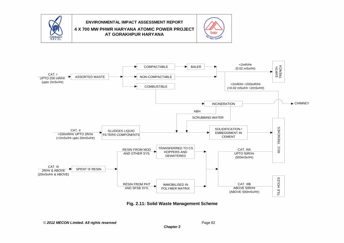
ENVIRONMENTAL IMPACT ASSESSMENT REPORT
4 X 700 MW PHWR HARYANA ATOMIC POWER PROJECT AT GORAKHPUR HARYANA
© 2012 MECON Limited. All rights reserved Page 82
Chapter 2
Fig. 2.11: Solid Waste Management Scheme
ASSORTED WASTECAT. I
UPTO 200 mR/Hr (upto 2mSv/Hr)
NON-COMPACTABLE
COMPACTABLE
COMBUSTIBLE
BALER<2mR/Hr
(0.02 mSv/Hr)
EAR
THTR
EN
CH
>2mR/Hr <200mR/Hr(>0.02 mSv/Hr <2mSv/Hr)
INCINERATION
RC
C T
RE
NC
HE
S
CHIMNEY
SOLIDIFICATION / EMBEDDMENT IN
CEMENT
SLUDGES LIQUID FILTERS COMPONENTS
CAT. II>200mR/Hr UPTO 2R/Hr
(>2mSv/Hr upto 20mSv/Hr)
SCRUBBING WATER
ABH
TILE
HO
LES
CAT. IIIBABOVE 50R/Hr
(ABOVE 500mSv/Hr)
CAT. IIIAUPTO 50R/Hr (500mSv/Hr)
TRANSFERRED TO CS HOPPERS AND DEWATERED
IMMOBILISED IN POLYMER MATRIX
RESIN FROM MOD AND OTHER SYS.
RESIN FROM PHT AND SFSB SYS.
CAT. III2R/Hr & ABOVE
(20mSv/Hr & ABOVE)SPENT IX RESIN

ENVIRONMENTAL IMPACT ASSESSMENT REPORT
4 X 700 MW PHWR HARYANA ATOMIC POWER PROJECT AT GORAKHPUR HARYANA
© 2012 MECON Limited. All rights reserved Page 83
Chapter 2
Resin Transfer and Fixation System Radioactive Spent Ion-Exchange resin is generated from Primary Heat Transport, Moderator, End shield / calandria vault cooling and Spent Fuel Storage and Inspection Bay (SFSB) clean-up systems in PWHR type reactors. These resins vary widely in dose rate, radio nuclide content and their concentrations.
Disposal of Resins with Short Lived Radioactivity Spent resins are transferred from the Ion Exchange vessel (Stainless Steel Hopper) of moderator, End Shield / Calandria vault cooling system, into a Carbon Steel Hopper, dewatered by compressed air and these CS Hoppers are disposed (after closure of all nozzle openings) in engineered barriers provided at Near Surface Disposal Facility (NSDF).
Disposal of Resins with Long Lived Radioactivity PHT / SFSB spent resins contain fission product radio-nuclides having long half life of about 30 years. These resins are required to be fixed in a monolithic block so as to prevent the release of radio-nuclides to environment. Conditioning of spent ion exchange resin in polymer / cement matrix is aimed at immobilising the resin in monolithic blocks and arresting release of radioactive nuclides to the environment. The resins are in the form of beads which are easily dispersed if not contained in a suitable matrix.
At WMP, Resin Transfer system and resin fixation system is provided at Ground floor (EL – 100.000 M) and is provided with all around shielding wall. All the equipment and piping, handing active resins, are provided with adequate shielding to have ease of operation and maintenance and also to reduce the back ground radiation level. The system material is of stainless steel for ease of decontamination.
Management of Spent Liquid Filters Spent liquid filters are received at WMP from various purification systems. PHT gland filters are disposable vessel type and are received in lead shielded casks. These vessels are disposed off after embedding the in-vessel cartridges in cement grout. Filter cartridges received from systems like SFSB purification, Fuel Handling System (FHS) and WMP are placed in a drum and immobilized by cementation before disposing in RCC trenches. Suitable shielded casks for transportation of the active filters are used.
Cementation of Sludge Active sludge from tank bottoms and sump are collected in a drum and fixed with cement matrix. Such solidified wastes are disposed in RCC trenches.
Volume Reduction of Category-I Solid Waste Using Baling Press (Compactor) A hydraulic Baling press with variable compaction force up to 70 Te is provided for soft compactable waste to achieve volume reduction before disposal. Generally a volume reduction factor of 5 can be achieved by this compaction method. However, this largely depends upon nature and composition of assorted waste received for compacting.
All compacted waste in drums are disposed off in earth trenches / RCC Trenches / Vaults after capping the drums.

ENVIRONMENTAL IMPACT ASSESSMENT REPORT
4 X 700 MW PHWR HARYANA ATOMIC POWER PROJECT AT GORAKHPUR HARYANA
© 2012 MECON Limited. All rights reserved Page 84
Chapter 2
Decontamination system (DC) An equipment Decontamination Centre is provided at WMP building for decontamination of removable and reusable small equipment, components, pipes, heavy water drums etc. having a maximum size of 600 mm dia. and 3500 mm length. This system provides surface decontamination of various parts using ultrasonic cleaning and steam.
Decontamination Centre (DC) is designed to decontaminate items having surface dose rate up to 0.01 Sv/hr. However, components having surface dose rate more than 0.01 Sv/hr and up to 0.1 Sv/hr, can be decontaminated using this system in Ultrasonic tank – I (UT-I) which is provided with a hematite shielded enclosure. In addition, special operating procedure will be made for handling such components having higher surface dose rate. Such components having surface dose rate more than 0.01 Sv/hr may come once in a while and not on a regular basis.
Laundry System An active laundry is provided to decontaminate clothing and rubber wears such as lab coats, hand gloves, Shoe cover, coveralls etc received from the station. The laundry equipment are provided to take care of the entire washing load of contaminated protective wears from HAPP – 1&2 on a single shift operation basis. However, increased load requirements, if any, during shutdown and other contingencies can be met by increasing the number of shifts. This system is located in reactor auxiliary building at EI 100.000 M very close to change room (point of generation) and new cloth issue room (point of utilization) thereby avoiding movement of contaminated clothing from change room to laundry system. The drain lines from these laundry machines are led to laundry waste collection sump from where it is filtered and pumped to laundry waste collection tank of dyke area.
Incineration of Low Level Combustible Solid Waste An oil fired incinerator is provided to incinerate organic liquid waste and low level (less than 2mR/hr) combustible solid waste (other than plastic waste). The off-gas is cleaned by two stage water scrubbers before discharging it through 30m tall chimney. Continuous monitoring system is provided to monitor the gas emitted from the chimney.
Solid Waste Disposal Solid wastes after conditioning will be disposed off in the Near Surface Disposal Facility (NSDF) area in earth trenches / RCC trenches / vaults / tile holes / HIC depending upon their surface dose rate. As a matter of practice packages having higher activity are disposed off at the bottom of trenches / vaults will be suitably sealed permanently as per established practices. These data will be utilised to assess the safety aspects of the waste repository. Necessary geo-hydrological & soil analysis studies for the NSDF site will be carried out to assess the safety of NSDF containing solid waste generated from 50 years of plant operation. Proper surveillance of Solid Waste Management Facility is carried out through bore holes provided all around the NSDF to check the integrity of the engineered barriers through periodic water sampling. Additional array of boreholes will be provided, whenever the facility is augmented. The NSDF area is fenced and necessary access control procedures are established. A waste assaying is carried out to

ENVIRONMENTAL IMPACT ASSESSMENT REPORT
4 X 700 MW PHWR HARYANA ATOMIC POWER PROJECT AT GORAKHPUR HARYANA
© 2012 MECON Limited. All rights reserved Page 85
Chapter 2
assess and record the radioactive content in each conditioned waste packages before disposing them. Name of the vault and their identification also recorded.
The dose rate on the top of the sealed earth trenches and RCC trenches / vaults would not exceed 0.01 mGy/h.
Spent Fuel Spent fuel is removed from the reactor core and transferred to spent fuel inspection bay (SFIB) where it is inspected for leaks / pin holes / damage. It is then stored in spent fuel storage bay (SFSB) which is under continuous radiological surveillance. The spent fuel is stored in SFSB till it cools down to dry storage level (about 5 years). Subsequent action on the spent fuel is dictated by the policy of the Department of Atomic Energy / Government of India.
Size of Spent Fuel Storage Bay The size of one SFSB can accommodate 10 years of spent fuel discharge and one core load.
2.16 SAFETY ANALYSIS
The objective of Safety Analysis is to demonstrate that the public is adequately protected from the effects of power plant operation and abnormal events that might occur during the plant life. It is to be ensured that the plant does not significantly add to the health risks to which individuals and society are already exposed.
The basic approach adopted in the safety analysis centers on:
1. Identifying all abnormal events during the plant life that can lead to radiation exposures, and their classification according to their probability of occurrence.
2. Identifying consequences of such events. The events are further classified in two categories.
1. Single failure events 2. Multiple failure events Single Failure Events A single failure is defined as a failure of a process system.
Multiple Failure Events Multiple failure events are defined as failure of a process system along with its associated safety system. Safety analysis will be carried out for typical single / multiple failure events in line with AERB safety guide.
Some example of postulated single failure / multiple failure are given below.
Safety analysis will be carried out for typical single / dual failure events :

ENVIRONMENTAL IMPACT ASSESSMENT REPORT
4 X 700 MW PHWR HARYANA ATOMIC POWER PROJECT AT GORAKHPUR HARYANA
© 2012 MECON Limited. All rights reserved Page 86
Chapter 2
List of Postulated Single Failures : Fuel failures Loss of Regulation Accident (LORA). Pipe failures in the PHT system (Loss of Coolant Accident – LOCA) Failure in Secondary Steam Line Loss of Feed Water Failures in Primary System (other than LOCA)
o Loss of coolant circulation (failure of primary circulating pump) o Channel flow blockage o Failure in PHT pressurizing system o Failure of shut down cooling system o Failures in Moderator System
- Loss of Moderator circulation - Fall in moderator level
Failure in shield and vault cooling systems (including loss of end shield water) Failure of electrical power supplies Failure in fuel handling system Failure of process water systems
List of Postulated Dual Failures Coincident failure of PHT system pressure boundary and Emergency Core Cooling
System Coincident failure of PHT system pressure boundary and Containment Isolation Fuel Handling Accidents Coincident with failure of containment
Following considerations are incorporated in the analyses in a conservative manner for evaluation of radiological consequences of the postulated accidents.
1. Behavior of fuel and fission product release from thermal or mechanically induced failures.
2. Coolant tube behavior under overheated conditions. 3. Response of the containment and associated engineered safety failures. 4. Dispersion of radioactive materials in the atmosphere.
Safety analysis will also cover the plant response to various operational transients originating from the internal or external disturbances and also equipment tripping / starting, which can be broadly classified as follows :
1. Secondary side events (eg, turbine trip, BFP trip steam leaks) 2. Plant power change events (eg, power drops) 3. Electrical disturbances (eg. Net load rejection, frequency swing) 4. PHT system malfunctions (eg. Pressurizing pump trip, pressure controller
malfunction)
In addition to the deterministic analysis mentioned above probabilistic safety analysis (PSA) will also be carried out.

ENVIRONMENTAL IMPACT ASSESSMENT REPORT
4 X 700 MW PHWR HARYANA ATOMIC POWER PROJECT AT GORAKHPUR HARYANA
© 2012 MECON Limited. All rights reserved Page 87
Chapter 2
It is demonstrated that under the design basis accident, the dose to the members of the public would not exceed 0.5 Sv (50 rem) to child thyroid and 0.1 Sv (10 rem) for the whole body.
2.17 PLANT LAYOUT AND MAIN PLANT BUILDINGS
2.17.1 Plant Layout
The latitude and longitude of the project site is shown in Fig. 2.12a and that of the township is given in Fig. 2.12b. The general layout of the proposed project is shown in Drg. No. HAPP-1 to 4 /70000/2002/GA (DR.LWS). Rev. 01. Composite plan of the main plant and colony is given in Drg. No. MEC/11/S2/Q6SY/01. Only barren land has been selected for the colony.
Fig. 2.12a : Longitude and Latitude of the Proposed Project Site
2.18 POWER REQUIREMENTS
During construction & commissioning Max 10 MW will be required which will be sourced from State Grid as follows: • Construction power supply will be drawn from the existing 33 KV/ 11 KV sub-station
nearby. • Start up / commissioning power from 220 KV sub-station. This sub-station will
connect to nearby 220 KV sub-station.

ENVIRONMENTAL IMPACT ASSESSMENT REPORT
4 X 700 MW PHWR HARYANA ATOMIC POWER PROJECT AT GORAKHPUR HARYANA
© 2012 MECON Limited. All rights reserved Page 88
Chapter 2
Fig. 2.12b: Longitude and Latitude of the Township at Badopal Village

ENVIRONMENTAL IMPACT ASSESSMENT REPORT
4 X 700 MW PHWR HARYANA ATOMIC POWER PROJECT AT GORAKHPUR HARYANA
© 2012 MECON Limited. All rights reserved Page 89
Chapter 2
2.19 WATER REQUIREMENTS 2.19.1 Provision of Water
The water requirement for the project (four units) will be met from Fatehabad Branch of Bhakra Canal. Assurance has been given to supply 783 Million Liters per Day (MLD) or 32625 m3/hr (9.07m3/sec or 320 cusecs) of water for consumptive use by the project including township from Haryana Government (Annexure III). Even during lean season, Haryana State Government has assured a full supply of 320 cusecs on a continuous basis.
The design discharge of this canal near the site RD 48,159 m (158000 ft) is 57.25 m3/sec (2021.70 cusecs). The average discharge in this canal for the last 10 years is 42.5 m3/sec (1500 cusecs). The canal has been in service since 1954-55 and is fully lined. The details of this canal near site are given in Table 2.5.
Table 2.5 : Details of Fatehabad Branch of Bhakra Canal near Project site Full supply level 216.45 (710.13 ft) Design discharge near the site 57.25m3/sec (2021.70 cusecs) Full supply depth 2.51 m (8.25 ft) Bed level 213.94 m (701.88 ft) Natural ground level near the canal 214.67 m (704.30 ft) Geographical co-ordinates of In take Point longitude 750 37’ 40” E and latitude 290 26’ 03” N. Geographical co-ordinates of outfall Point longitude 750 36’ 25” E and latitude 290 26’ 44” N.
Water Supply during Canal Closure The canal is closed for about 2 weeks once in 10 years. During such situations, so as to maintain continuous committed water supply, Government of Haryana has assured that both of the parallel Fatehabad branch canals will not be closed at a time and water through one of the parallel canal will be available to meet the requirement of the project. Simultaneously, NPCIL is also exploring the possibility to ensure availability of water for nuclear safety of 1 cusec / unit through an alternative source of water like Yamuna Canal system.
In case of canal closure, specific design provision exist for removal of nuclear decay heat and storage of low level liquid effluents at site which will not be discharged in the canal.
2.19.2 Water Balance The Government of Haryana has made commitment to NPCIL for availability of 320 cusec (32,652m3/hr) of water. NPCIL will carry out its activities including all conditions of the plant operations within this sanctioned water.
The water from Bhakra Canal will be stored in 1512000m3 Plant Makeup Storage Reservoir. The water balance diagram for unit 1 & 2 of HAPP is given in Fig. 2.13. The water requirement for two units will be 9000 m3/hr and that for all the four units will be 18000m3/hr. Out of which 12680 m3/hr will be towards consumptive use and the rest of the 5320 m3/hr will be returned to canal. The return flow will be utilized for low level treated liquid waste dilution purpose. This return flow led to canal will meet the

ENVIRONMENTAL IMPACT ASSESSMENT REPORT
4 X 700 MW PHWR HARYANA ATOMIC POWER PROJECT AT GORAKHPUR HARYANA
© 2012 MECON Limited. All rights reserved Page 90
Chapter 2
requirement stipulated by AERB and State Pollution control Board and there will not be any restrictions on any use on downstream side.
2.19.3 Cycle of Concentration of Water
The estimated rate of water consumption for 4X700 MWe will be to the tune of 4.5 m3/hr per MWe, taking cycle of concentration (COC) as 3. The major portion of this water is lost through evaporation in evaporation tower and thus further reduction in water consumption is not possible. The COC for HAPP, Haryana power project the COC value of three is worked out based on studies carried out at Kakarapar site considering the optimization of techno commercial considerations, water chemistry, nuclear safety and water conservation.
2.20 CONSTRUCTION FACILITIES
• All construction facilities like stone, metal, aggregate etc from Tosham village which is about 40 km from Hisar and from other places like Chandigarh and Delhi.
• Sand would be sourced from Karnal and / or Ghaghar river. • Construction power supply of about 10 MW is available from nearby 33 KV /11 KV • Water for construction purpose will be drawn from nearby canal system.
2.21 POWER EVACUATION
• Power evacuation lines from project to major load centers at Hisar, Bhivani,
Fatehabad, Bahadurgarh and other load centers in northern grid through Centralised Transmission Utility (CTU).
• Power Evacuation “in principal” is feasible for 2800 MWe power from site. The Power generated at HAPP will be evacuated through 400 kv transmission system. The number of transmission outlets and their destination will be finalized taking into account share of beneficial state in due course after a detailed power system studies are carried out by PGCIL and approved by the concerned authorities “
2.22 ASSESSMENT OF NEW & UNTESTED TECHNOLOGY FOR THE RISK OF
TECHNOLOGICAL FAILURE The PHWR technology in India is evolved based on the extensive expertise developed indigenously. As of now India is self reliant in this technology and successfully, designing, commissioning and operating 220 and 540, MWe PHWRs. It is a matter of satisfaction that India has designed the latest 700Mwe PHWR which are under constructed at Kakrapara and Rawatabhata sites. It is envisaged to implement the similar 700Mwe PHWR at the proposed Haryana site.
2.23 PROJECT COST
The estimated cost of 2X700MWe PHWR (Pressurised Heavy Water Reactor) Atomic Power Project along with the residential complex at Gorakhpur, District Fatehabad, Haryana is about Rs. 11751 Crores (estimates based on base cost of 2011-12) and that for 4x700MWe is about Rs 23502 Crores (base cost 2011-12).
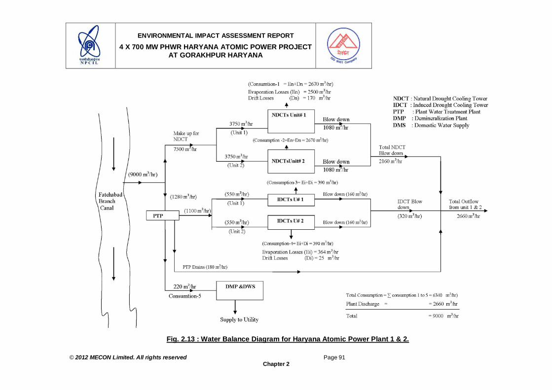
ENVIRONMENTAL IMPACT ASSESSMENT REPORT
4 X 700 MW PHWR HARYANA ATOMIC POWER PROJECT AT GORAKHPUR HARYANA
© 2012 MECON Limited. All rights reserved Page 91
Chapter 2
Fig. 2.13 : Water Balance Diagram for Haryana Atomic Power Plant 1 & 2.

ENVIRONMENTAL IMPACT ASSESSMENT REPORT
4 X 700 MW PHWR HARYANA ATOMIC POWER PROJECT AT GORAKHPUR HARYANA
© 2012 MECON Limited. All rights reserved Page 92
Chapter 2
2.24 RESIDENTIAL COMPLEX OF HAPP 2.24.1 Basic Features and Site Plan
The proposed township is located at a distance of 6 Km from project, within 3 Km of Badopal village and approximately 28 km from Fatehabad. The township site is barren land and doesn’t involve any rehabilitation. The soil is alluvial and the land is almost plain terrain. The area comes under earthquake zone III as per IS 1893:2002 (Part-I) Fifth Revision. The buildings/structures will be designed in accordance with IS-1893 for earthquake resistance. The site plan of the township site and its surroundings with physical features and topographical details, such as land use, contours and drainage pattern shown in Drg. No. MEC/11/S2/Q6SY/01 and MEC/11/S2/Q6SY/02. The photographs of the site is shown in Fig. 2.14a & 2.14d. After site acquisition a detailed topographical survey of the township site and surrounding areas will be conducted and keeping in view of all the site features in consideration a master plan for the township will be prepared taking in to consideration the followings:
Water supply, Storm water drainage, sewerage, power, etc., Disposal of treated wastes from the complex on land / water body and into
sewerage system. The proposed facilities in the township includes, Environmental Survey Laboratory, Residential Buildings, Shopping Complex, Hospital, Dispensary, Recreation Club, Parks, Senior Hostel, Junior Hostel, Guest House, Maintenance Office, Civic Amenities and Services etc. A conceptual plan of the township is shown in Fig. 2.15. The main features of the township are as follows: a. Land area is : 75 Ha b. Ground Coverage area : 28.4 Ha (37.8%) c. Built up area = 26.00 Ha [Floor Space Index (FSI2) : 0.34]. d. The township will have a maximum height of Ground + two stories limited to
maximum height of 11.45 m. e. Water Consumption = 1.250 Million Liters Per Day (MLD) or 1250 m3/d f. Power requirement = 2000 KVA for stage one and 2000 KVA for stage two. A 500
KVA Standby DG set will be provided. g. Connectivity: Via local roads near Badopal village on National High way number
(NH-10) connecting Hisar and Fatehabad. h. Parking requirements: Adequate parking space of about 1500 cars, light commercial
vehicles, buses etc. is available in the township.
2 Floor Space Index (FSI) = Total floor area including walls of all floors / Plot Area / Building Unit

ENVIRONMENTAL IMPACT ASSESSMENT REPORT
4 X 700 MW PHWR HARYANA ATOMIC POWER PROJECT AT GORAKHPUR HARYANA
© 2012 MECON Limited. All rights reserved Page 93
Chapter 2
Fig. 2.14a : View of Township Site (February 2012)

ENVIRONMENTAL IMPACT ASSESSMENT REPORT
4 X 700 MW PHWR HARYANA ATOMIC POWER PROJECT AT GORAKHPUR HARYANA
© 2012 MECON Limited. All rights reserved Page 94
Chapter 2
Fig. 2.14b : View of Township Site - Prosopis juliflora Growth in Waste Land
(February 2012)

ENVIRONMENTAL IMPACT ASSESSMENT REPORT
4 X 700 MW PHWR HARYANA ATOMIC POWER PROJECT AT GORAKHPUR HARYANA
© 2012 MECON Limited. All rights reserved Page 95
Chapter 2
Fig. 2.14c : View of Township Site (February 2012)

ENVIRONMENTAL IMPACT ASSESSMENT REPORT
4 X 700 MW PHWR HARYANA ATOMIC POWER PROJECT AT GORAKHPUR HARYANA
© 2012 MECON Limited. All rights reserved Page 96
Chapter 2
Fig. 2.14d : Road Leading by the Side of Township Site (February 2012)

ENVIRONMENTAL IMPACT ASSESSMENT REPORT
4 X 700 MW PHWR HARYANA ATOMIC POWER PROJECT AT GORAKHPUR HARYANA
© 2012 MECON Limited. All rights reserved Page 97
Chapter 2
i. Community facilities: Hospital, Community centre, School and shopping centre recreation club, sports complex, play ground, bank, post office, petrol pump etc. will be provided in the proposed township.
j. All the civic amenities. k. Measures to minimize energy consumption
Use of CFL3 Use of Low-pressure sodium lamps for outdoor lighting along the road and
security lighting with Solar Street Lights mix. Use of solar water heater for hospital, guest house. Automatic timing control mechanism will be incorporated in the street lighting to
save energy. Mechanism will involve staggering of on-off sequence of street lights.
l. A sewage treatment plant is envisaged for treatment of sewage water. The treated sewage shall be disinfected / filtered and used for gardening purpose.
m. Green belt will be developed in and around the township. n. A fire extinguishing system as per the requirements of national Building Code will be
provided.
2.24.2 Power Requirement
a. The energy consumption will be 1kwh/ sqf per unit. b. Total power requirements will be 2000KVA + 2000KVA for both the stages. . c. 500 KVA Standby DG set shall be provided.
2.24.3 Water Requirement
The total requirement of the proposed township has been worked out on average consumption of 135 lpcd4 water for individuals in residential buildings and of 35 lpcd in case of institute like schools etc. On an average five persons per flat are considered in residential areas. In case of hospital the consumption of 350 lpcd including laundry etc has been envisaged. The breakup of the total water requirement for the township is shown in Table 2.6. The water supply source will be Fatehabad branch of Bhakra Canal and stored rainwater. Water demand shall be around 0.625 MLD (maximum) during stage 1 and 1.25 MLD at the beginning of Stage-II. Assurance has been given to supply water for the township from Haryana Government (Annexure III).
Table 2.6 : Breakup of Total Water Requirement for Township
SN. Type of Quarter / Building No of Quarters
Estimated No of Persons
Consumption in Liters /Day
1 F-Type 4 20 2700 2 E-Type 110 550 74250 3 D-Type 512 2560 345600 3 C-Type 1004 5020 677700
3 Compact fluorescent lamp (CFL) or Compact Fluorescent Light 4 Liters per capita per day

ENVIRONMENTAL IMPACT ASSESSMENT REPORT
4 X 700 MW PHWR HARYANA ATOMIC POWER PROJECT AT GORAKHPUR HARYANA
© 2012 MECON Limited. All rights reserved Page 98
Chapter 2
SN. Type of Quarter / Building No of Quarters
Estimated No of Persons
Consumption in Liters /Day
4 Hospital 4A No of Beds 50 50 17500 5 School 2000 70000 6 Guest House with 50 rooms (occupancy 50%) 25 3375 7 Service Personnel Hostel 30 100 3500 8 Junior Hostel 30 60 8100 9 Senior Hostel 60- 60 8100 10 Shopping Centre & Convenience Shopping
Centre 30 1050
11 Community Centre 30 1050 12 Barrack 234 234 31590 13 Single Officer Hostel 48 48 6480 14 Administration Building 50 1750 15 Environmental Survey Lab 15 2025 16 Club House 25 875 Grand Total 1255645 Say in m3/d 1250.0 Total Water requirement in liters per second (LPS) 14.5 Total Water requirement in Cubic Foot Per Second (Cusec) 0.52
2.25 BASELINE ENVIRONMENTAL SCENARIO
The baseline environmental study for HAPP project including the township was conducted during summer season from March 2011 to May 2011. The same is described in detail in Chapter 4. Hence the same is not being repeated here.
2.26 IMPACTS AND MITIGATION MEASURES DUE TO PROJECT SITING (LOCATION)
The impacts and mitigation measures due to project siting or locating the project at the proposed site including the residential complex is detailed in Section 5.2, Chapter 5. However, the impacts and mitigation measures specifically for the following aspects related to the residential complex are described hereunder.
2.26.1 Application of R & R Policy
The project location may lead to displacement of people and loss of land to local population. The project site is located in Gorakhpur Village in Bhuna Block of Tehsil, Sub-division and District Fatehabad of Haryana State as shown in Fig. 2.1 (Chapter 2). The impact due to siting of the project is that a total of 75.04 ha land is to be acquired and the total PAPs involved are 125. Only land oustees and no homestead are involved in the project. Due compensation will be provide to the Project Affected People (PAPs) as per the R & R Policy 2010 of Haryana State (for details refer Section 5.2, Chapter 5).

ENVIRONMENTAL IMPACT ASSESSMENT REPORT
4 X 700 MW PHWR HARYANA ATOMIC POWER PROJECT AT GORAKHPUR HARYANA
© 2012 MECON Limited. All rights reserved Page 99
Chapter 2
Fig. 2.15 : Conceptual Plan of the Township

ENVIRONMENTAL IMPACT ASSESSMENT REPORT
4 X 700 MW PHWR HARYANA ATOMIC POWER PROJECT AT GORAKHPUR HARYANA
© 2012 MECON Limited. All rights reserved Page 100
Chapter 2
2.26.2 Maintenance of Area Drainage Pattern The location of the project may obstruct the drainage pattern in the area. Township is located in a low rainfall zone. There are no natural drainage channels in the area. Care will be taken while designing the master plan that natural drainage pattern / slope of surroundings is not obstructed. The same will be incorporated in the landscaping. Proper drainage scheme using network of storm water drains will be incorporated, with no flooding of nearby areas. Township buildings are proposed to be built on level ground. Care will be taken to divert the water from these areas, using adequate storm water drains to the nearest water charging pits. Since, the building design corresponds to site topography, minimal cut and fill are envisaged.
2.27 IMPACT AND MITIGATION MEASURES DURING CONSTRUCTION STAGE The impacts and mitigation measures during the construction stage for the total project including the residential complex is detailed in Section 5.4, Chapter 5, covering impact and mitigation measures envisaged for:
Land-use (Section 5.4.1, Chapter 5) Air Quality (Section 5.4.3, Chapter 5) Water Quality (Section 5.4.4, Chapter 5) Noise (Section 5.4.5, Chapter 5) Site Security (Section 5.4.6, Chapter 5) Industrial Safety (Section 5.4.7, Chapter 5)
However, the impacts and mitigation measures specifically for the following aspects related to the residential complex are described hereunder.
2.27.1 Soil Erosion, Topography and Rainfall
During construction stage large scale soil erosion may take place at the construction site. The average rainfall in the area in last five years is about 291mm (Table 4.10a), which indicates that the area is arid to semiarid. The township site is barren land and doesn’t involve any rehabilitation. The soil is alluvial and the land is almost plain terrain. Thus chances of soil erosion due to rain are less. However, due care will be taken during construction phase that excavation and construction activities which causes soil erosion is not taken up during rainy season. Moreover, garland drain at suitable places around the site of construction will be places to arrest soil from the construction site.
2.27.2 Impact on Flora and Fauna
The construction of the township may cause disruption of flora and fauna at the project site. The details of flora and fauna as present in the area are detailed under Section 4.2.6, Chapter 4. The residential complex project site is almost barren as shown in Fig. 2.14a and 2.14b. During construction phase all care will be taken to cause minimum

ENVIRONMENTAL IMPACT ASSESSMENT REPORT
4 X 700 MW PHWR HARYANA ATOMIC POWER PROJECT AT GORAKHPUR HARYANA
© 2012 MECON Limited. All rights reserved Page 101
Chapter 2
disturbance to the existing flora and fauna at the project site. Moreover, while designing the township proper landscaping will be done and adequate green area, green belt and avenue plantation will be undertaken to make a positive contribution to the status of flora and fauna in the area.
2.27.3 Use of Local Building Material
The site is not in low lying area. It is a almost flat terrain no filling is required at the township site. Sourcing of raw material during construction stage may cause environmental concern to the site from where the material is being sourced. During construction all efforts will be made to use local building material and due care will be undertaken to avoid all environmental concerns arising due to sourcing of local building material (for details refer Section 5.4.1, Chapter 5).
2.28 IMPACT AND MITIGATION MEASURES DURING OPERATION PHASE
The impacts and mitigation measures during the operation phase for the total project including the residential complex is detailed in Section 5.5, Chapter 5. However, the impacts and mitigation measures specifically for the following aspects related to the residential complex are described hereunder. During operation phase of a residential complex impacts may be due to sewage disposal, solid waste disposal and traffic congestion. Moreover, issues like water, energy conservation, education and health facilities, etc. also needs to be addressed. The mitigation measures on the above aspects during operation phase of the residential complex are described under following subheads.
2.28.1 Sewage Treatment Facilities and Guard Pond
The untreated sewage of the township may cause water pollution in the receiving water bodies. A sewage treatment plan has been envisaged for the residential complex. The total quantum of sewage waste generated from the township will be 816 KL/day (@ 75 lpcd). However, to treat the same a sewage treatment plant of 1.0 Million Liters Per day (MLD) has been envisaged. The swage treatment plant will employ the highest degree of biological treatment using Sequencing Batch Reactor technology which will not only achieve higher biodegradation level but clear water also. The treated sewage shall be disinfected and filtered. pH – 6.5 to 8.5, TSS < 30 mg/l, BOD< 10 mg/l. Treated sewage will be utilized for irrigating plantation and green belt in the residential complex and only excess water will be let out of the residential complex. The out let water will meet the statutory norms. The stabilized dried sludge cake obtained from STP will be utilized as manure for the plantation. Additionally, for storm water, a suitable scheme will be designed such that the storm water drain does not have any adverse impact on the near by water body. It will be collected and utilized through a rain water harvesting scheme as described in Section 2.28.5.

ENVIRONMENTAL IMPACT ASSESSMENT REPORT
4 X 700 MW PHWR HARYANA ATOMIC POWER PROJECT AT GORAKHPUR HARYANA
© 2012 MECON Limited. All rights reserved Page 102
Chapter 2
A guard pond will be provided in parallel to sewage treatment plant to store the domestic wastewater in case breakdown or failure of wastewater treatment facility. The guard pond will have capacity of 2000 m3 storage area for retaining wastewater during repair of treatment plant. An adequate out fall for discharge of treated sewage from township will be planned. The residential complex of JNPP will be provided with a guard pond and a sewage treatment plant (STP) for hold of slightly polluted water generated during various activities in the residential complex and treatment of sewage from the houses and other facilities. The design parameters of the STP shall be based on the conditions given in Table 2.7a. The design criteria for different units in sewage treatment plant are given in Table 2.7b. The flow sheet of sewage treatment plant is shown in Fig. 2.16. The STP system will comprise the following sections: Primary Treatment
- Screen Chamber - Grit Chamber - Sewage Collection Sump
Biological Treatment - Fluidized Bed Bio Reactor (FBR) - Clarisettler
Tertiary Treatment - Chlorine Contact Tank - Dual Media Filter - Activated Carbon Filter
Sludge Handling / Guard Pond - The sludge drying beds / pond of suitable capacity will be designed to dry the
sludge generated from the sewage treatment plant during its normal operation as well as its break down. In case of failure of the STP, the sewage will be pumped to the guard pond directly to allow the gravity settling of the solid waste / sludge. This sludge will be removed from the guard pond regularly and will be used as manure for development of green belt at the project site and residential complex.
Table 2.7a : Sewage Treatment Plant : Design Parameters (Total Flow : 1000m3/day)
SN. Parameters Before Treatment
After Treatment (Before Dual Media Filter)
After Treatment (After Carbon Filter)
1 pH 7.65 7 to 8 6.5 to 8 2 BOD (mg/I) 250 < 20 5 to 10 3 COD (mg/I) 350 <100 50 to 80 4 TSS (mg/I) 250 < 30 10 to 15
Table 2.7b : Sewage Treatment Plant: Design Criteria
SN. Description of Treatment Units Value to be Considered for Design
Range of Value Specified by the Codes
1 Screen Chamber - Velocity through screen 0.75 m/sec 0.6 to 1.2 m/sec

ENVIRONMENTAL IMPACT ASSESSMENT REPORT
4 X 700 MW PHWR HARYANA ATOMIC POWER PROJECT AT GORAKHPUR HARYANA
© 2012 MECON Limited. All rights reserved Page 103
Chapter 2
- Clear openings 20 mm 20 to 50 mm 2 Grit Chamber - Detention time 60 sec 30 to 60 sec 3 Sewage Collection Sump at STP - Detention time 6 hrs 6 to 8 hrs - Air requirement for mixing 750 to 800 m3/d 0.9 m3/m3 of tank volume 4 FBR (Two Stages) - Organic loading rate 3.2 to3.6 kg BOD/m3/d 3.2 to 3.6 kg BOD /m3 /d - Oxygen required 2.0 kgO2/kg BOD
removed 1.5 to 2.0 kg O2/ kg BOD removed
- Oxygen transfer efficiency 12 % 8 - 12 % 5 Clarisettler - Detention time 12 - 2.0 hrs 15 - 2.0 hrs 6 Sludge Drying Beds - Drying cycle 10 - 12 days 6 - 12 days
7 Chlorine Contact Tank - Detention time 45 - 60 min 30 - 60 min - Dosage To be maintained so that
residual chlorine is 2ppm
2.28.2 Domestic Solid Waste Management at Township
The solid waste generated from the residential complex if not properly disposed may cause foul smell, un-aesthetic look, and land and water pollution in the area. A municipal solid waste management plan has been envisaged for the project. There are about 1700 dwelling unit at township. It is estimated that about 3800kg of waste will be generated per day, out of which about 3290kg will be compostible waste and 510kg will be non-compostible / recyclable waste. It has been planned to segregate the two types of waste at the source and right up to final disposal. Separate bins for compostlble and non-compostible waste, will be provided at each dwelling unit. The two type of waste from each house will be collected in to respective area bins designated for compostible and non-compostible waste. From area bins the two type of waste will be transported separately to central garbage station located at remote place in the township to avoid foul smell in the area. The entire area of the central garbage station will be fenced and thick plantation will be done all around the same. The non-compostible waste from central garbage bins will be sent to municipal solid waste dumping ground of Fatehabad / Hisar district. The compostible waste will be composted in pits with vermin-culture technique. The exact details of the vermin-culture composting will be worked out in consultation with Hisar Agriculture University. However, the basic concept should be adequate number and size of vermin-culture pits will be there to collect compostible waste from 2 weeks to 4 weeks and once the running pit is closed another pits are ready to receive the compostible waste being collected from the township. Thus sufficient number of pits will

ENVIRONMENTAL IMPACT ASSESSMENT REPORT
4 X 700 MW PHWR HARYANA ATOMIC POWER PROJECT AT GORAKHPUR HARYANA
© 2012 MECON Limited. All rights reserved Page 104
Chapter 2
be worked out so that to run the pits in rotation taking into consideration the time taken by a closed pit to decompose completely and time required evacuating the pit of manure and the rate of compostible waste generation in the township. The compost by vermin-culture will be sold to the township houses for use in their kitchen garden. The excess will be distributed free to the local farmers.
2.28.3 Traffic Management
Mass scale movement of residents of the township may cause traffic congestion the area. Considering the traffic load in the area, an adequate traffic management plan has been envisaged. As per the master plan of the complex, no public road or highways (state or national) will be allowed to pass through the residential complex. The official and private vehicles of the employees will be parked in the residential complex at designated places and in the stilt area provided in the residential buildings. The roads will be provided with footpaths on both the sides of the roads and other essential road safety features. It is envisaged that there would not be any loading / unloading heavy machinery and component in the residential complex. All the official vehicles will be regularly checked and maintained for their road worthiness. During baseline data generation traffic survey was carried out during week days and week ends at NH10 and road connecting NH10 to project site (Chapter 4, Tables 4.9a1 & 4.9a2 and 4.9b1 & 4.9b2), the traffic on the week ends is slightly more on the NH10 and road connecting NH10 with project site as compared to the weekdays. Detailed traffic management plan for the project and the township has been planned taking in to consideration the existing traffic load in the region (Section 5.5.3.7, Chapter 5).
2.28.4 Education and Health Facilities, Police and Other Services
The education, health, police and other facilities, post and telegraph, transport, etc in the area is described in detail in Chapter 8, under Section 8.2.4. The above facilities in the area considering a rural setup are adequate. The same may get overloaded due to the residential project. Provisions have been made that all such basic facilities will be made available to the residents of the township - matching to the facilities as available in cities. The same will be accordingly planned and setup in the township.

ENVIRONMENTAL IMPACT ASSESSMENT REPORT
4 X 700 MW PHWR HARYANA ATOMIC POWER PROJECT AT GORAKHPUR HARYANA
© 2012 MECON Limited. All rights reserved Page 105
Chapter 2
Fig. 2.16: Flow Sheet of Sewage Treatment Plant DMF – Dual Media filter, ACF- Activated Carbon Filter, FBR- Fixed Bed Reactor

ENVIRONMENTAL IMPACT ASSESSMENT REPORT
4 X 700 MW PHWR HARYANA ATOMIC POWER PROJECT AT GORAKHPUR HARYANA
© 2012 MECON Limited. All rights reserved Page 106
Chapter 2
2.28.5 Rain Water Harvesting
Large scale residential complex may cause water crises in the area. All measures have been taken to ensure minimum wastage of water. A detailed rain water harvesting scheme will be designed and implemented. After site acquisition a detailed soil investigation will be carried out to design the rain water harvesting system – so as to take in to account the soil characteristics and permeability of rainwater to ground water table with due safeguards for ground water quality. Provision for rain water harvesting has been provided in the township only so as to avoid any chances of pollutants percolation to ground water through harvested rain water. In the township, runoff from hard surfaces and landscaped areas will be collected through catch basins interlinked with pipe network or grated open drains. Rainwater from terraces and open areas to be diverted to catch basins through down take pipes. Details of water harvesting structures are as follows: a. The total annual average rainfall in the area of interest is 358 mm approximately. b. The total roof area is 106415 sq m. and the run off coefficient is 0.7. The total water
available from the roof area will be 26663 m3 will be available c. The catchment area is 643600 sq m with a run off coefficient of 0.2. The total water
available will be 46081 m3. d. The total rain water that can be made available will be 72,744 m3. Same will be
made available for gardening and ground water recharging. e. Water harvesting pits would be constructed in the township area and runoff from the
rooftops and hard landscape areas would be diverted into these pits. Separate pits would be provided for the different buildings in the Complex and all pits would be provided with sedimentation/ siltation chamber.
f. RCC or Polystyrene tanks would be created to store and reuse runoff from roof surfaces. Each of these tanks would be provided with a roof washer to ensure water quality is maintained. Apart from this, different recharge structures would also be used to recharge groundwater. These are: Storage tanks of appropriated size will be provided. Recharge trenches with Bore-wells of appropriate size will be provided. Gabion structures these would be provided with a wire mesh of 5mm dia wires. Percolation pond: A percolation of suitable size would be provided. Desilting
chambers and filtration chambers would be provided adjacent to these recharge structures.
If required, catchment drains will also be provided.
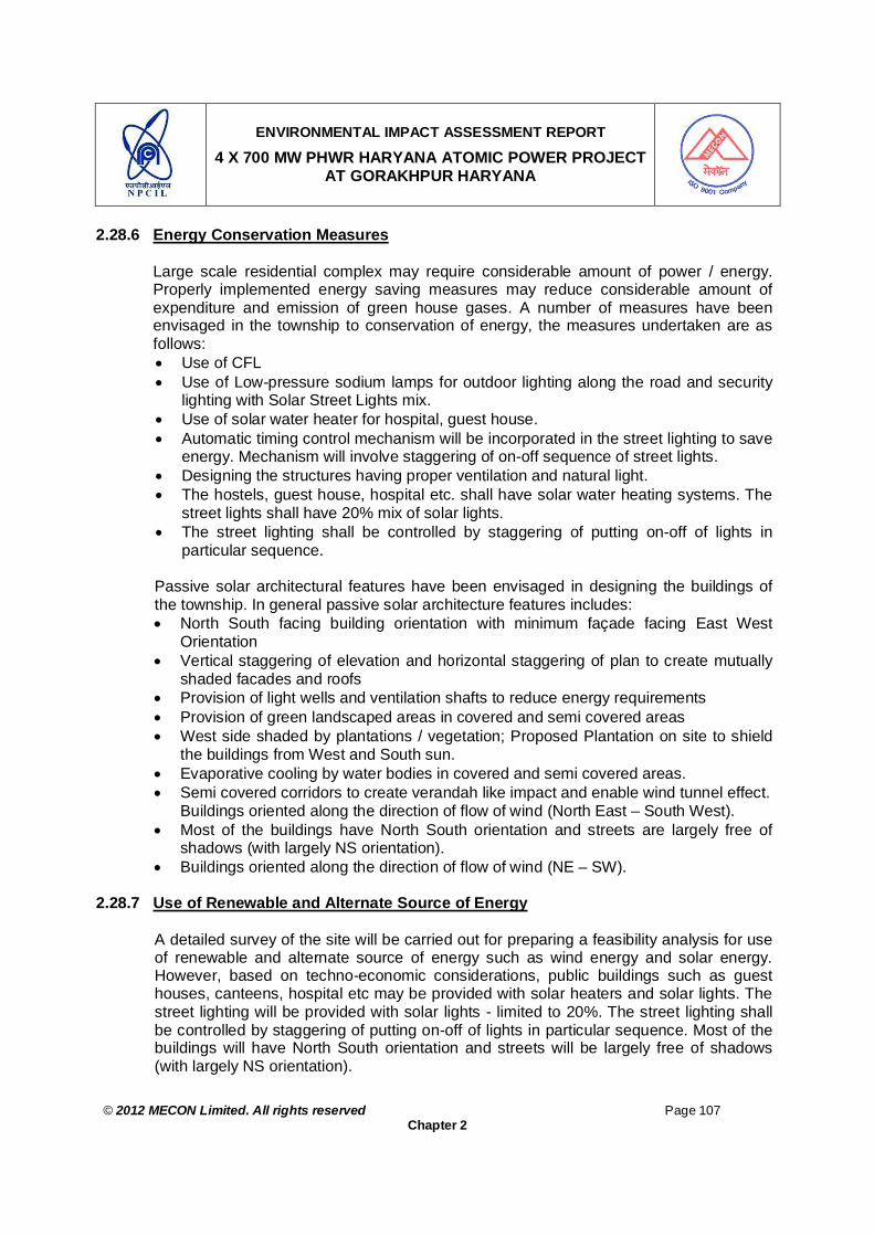
ENVIRONMENTAL IMPACT ASSESSMENT REPORT
4 X 700 MW PHWR HARYANA ATOMIC POWER PROJECT AT GORAKHPUR HARYANA
© 2012 MECON Limited. All rights reserved Page 107
Chapter 2
2.28.6 Energy Conservation Measures
Large scale residential complex may require considerable amount of power / energy. Properly implemented energy saving measures may reduce considerable amount of expenditure and emission of green house gases. A number of measures have been envisaged in the township to conservation of energy, the measures undertaken are as follows: Use of CFL Use of Low-pressure sodium lamps for outdoor lighting along the road and security
lighting with Solar Street Lights mix. Use of solar water heater for hospital, guest house. Automatic timing control mechanism will be incorporated in the street lighting to save
energy. Mechanism will involve staggering of on-off sequence of street lights. Designing the structures having proper ventilation and natural light. The hostels, guest house, hospital etc. shall have solar water heating systems. The
street lights shall have 20% mix of solar lights. The street lighting shall be controlled by staggering of putting on-off of lights in
particular sequence.
Passive solar architectural features have been envisaged in designing the buildings of the township. In general passive solar architecture features includes: North South facing building orientation with minimum façade facing East West
Orientation Vertical staggering of elevation and horizontal staggering of plan to create mutually
shaded facades and roofs Provision of light wells and ventilation shafts to reduce energy requirements Provision of green landscaped areas in covered and semi covered areas West side shaded by plantations / vegetation; Proposed Plantation on site to shield
the buildings from West and South sun. Evaporative cooling by water bodies in covered and semi covered areas. Semi covered corridors to create verandah like impact and enable wind tunnel effect.
Buildings oriented along the direction of flow of wind (North East – South West). Most of the buildings have North South orientation and streets are largely free of
shadows (with largely NS orientation). Buildings oriented along the direction of flow of wind (NE – SW).
2.28.7 Use of Renewable and Alternate Source of Energy
A detailed survey of the site will be carried out for preparing a feasibility analysis for use of renewable and alternate source of energy such as wind energy and solar energy. However, based on techno-economic considerations, public buildings such as guest houses, canteens, hospital etc may be provided with solar heaters and solar lights. The street lighting will be provided with solar lights - limited to 20%. The street lighting shall be controlled by staggering of putting on-off of lights in particular sequence. Most of the buildings will have North South orientation and streets will be largely free of shadows (with largely NS orientation).

ENVIRONMENTAL IMPACT ASSESSMENT REPORT
4 X 700 MW PHWR HARYANA ATOMIC POWER PROJECT AT GORAKHPUR HARYANA
© 2012 MECON Limited. All rights reserved Page 108
Chapter 2
Energy conservation measures as given under Section 2.24.1.k will be implemented. Use of energy efficient devices such as CFL etc. may be used for all public buildings in the residential complex.
2.28.8 Aesthetics Unplanned residential complex may give an ugly look to the surroundings. The master plan of the residential complex will be so designed so as to give an aesthetic look to the surroundings, especially the features described under Section 2.28.9 & 2.28.10. Further, good quality roads will be maintained in the residential complex along with traffic guidelines near sensitive areas like schools, colleges, hospitals and markets. Belt of avenue trees on both sides of the roads will be maintained apart from parks, tree plantation around public buildings and waste management areas. The commercial places like guest house, hostels, market place, and playing ground will be away from residential zones.
2.28.9 Landscape Plan, Green Belts and Open Spaces
The total land area for the project is 75 ha, out which the ground coverage is 28.4 ha (37.8%) and the built-up area will be 26.0 ha with FSI as 0.34. Thus it can be seen that sufficient open spaces have been envisaged which will be suitably land escaped and planted with green belt and lawns. A conceptual plan of the township is shown in Fig. 2.15.
2.28.10 Landscape Development and Roadside Plantation in Residential Complex
The residential complex site will be leveled and compacted. Subsequently, at suitable locations and identified places as per master plan, landscape gardens, and lawns will be developed with the fertile soil brought from the nearby areas and mixed with the manure generated from the municipal solid waste management plant at the residential complex of HAPP. The township boundary will be planted with green belt all around as given under Section 6.4.3, Chapter 6. The approach roads in the residential complex will be planted with avenue and ornamental trees as suggested in Section 6.4.3, Chapter 6 for avenue, vacant spaces and around office and other buildings. In 10 m area on both sides of road will be planted large, medium and small trees alternating with each other. Besides this, all the local voluntary organizations will be encouraged to undertake massive plantation along the roadside at suitable places to uplift the regional ecosystem of the area.
2.28.11 Disaster Management Plan for Residential Complex of HAPP
The residential complex is the integral part of the project. The risk assessment and emergency preparedness plan as presented in Chapter 9 will be applicable to

ENVIRONMENTAL IMPACT ASSESSMENT REPORT
4 X 700 MW PHWR HARYANA ATOMIC POWER PROJECT AT GORAKHPUR HARYANA
© 2012 MECON Limited. All rights reserved Page 109
Chapter 2
Residential Complex also. Hence during any emergency situations arising due to natural disasters and man made such as earthquake, cyclone/ flooding and radiological emergencies will be dealt in line with the plan as presented in Chapter 9.
2.28.12 Security
The residential complex will be secured by fencing and no unauthorized entry will be permitted in the construction area.
2.29 ENVIRONMENT MONITORING PROGRAMME The monitoring and evaluation of the mitigation measures envisaged are critical activities in implementation of the Project. Monitoring involves periodic checking to ascertain whether activities are going according to the plans. It provides the necessary feedback for project management to keep the program on schedule. A detailed environmental monitoring programme has been envisaged for the atomic power and the residential complex project covering the construction and operation stages of the project (for details refer Chapter 7.0).

ENVIRONMENTAL IMPACT ASSESSMENT REPORT
4 X 700 MW PHWR HARYANA ATOMIC POWER PROJECT AT GORAKHPUR HARYANA
© 2012 MECON Limited. All rights reserved Page 110
Chapter 3
CHAPTER 3 : ANALYSIS OF ALTERNATIVES - TECHONOLOGY AND SITE
3.0 ANALYSIS OF ALTERNATIVES : TECHNOLOGY & SITE
The Department of Atomic Energy (DAE) has an ongoing programme for development of Nuclear Power by pursuing different technologies. Accordingly, three stage programme for generation of nuclear power has been adopted. The First Stage program involves utilization of available resource of natural Uranium in the country for generation of nuclear power by Pressurized Heavy Water Reactor (PHWR) technology. The Second Stage program involves Fast Breeder Reactor (FBR) technology wherein plutonium is utilized, which is obtained by reprocessing spent fuel from PHWR units from first stage and at the same time using Thorium as blankets in these type of reactors, which will be converted into uranium. The Third Stage involves use of uranium obtained from second stage and later on from third stage itself as fuel and thorium as blanket (which is available in abundance in India) and will be converted into uranium for long term energy generation. In order to meet the growing demand of electricity in the country, Government of India has decided to enhance the share of nuclear power in overall electricity generation of the country. In order to meet the gap between supply and demand, it has been planned to generate nuclear power by importing reactors of LWR technology from various countries. A beginning has been made in this line by importing 2 x 1000 MWe VVER reactors of LWR technology from Russian Federation, which are at the advanced stage of construction at Kudankulam, Tamil Nadu State. Due to International embargo, the above mission could not be further pursued in the past but as a sequel to the Nuclear Supplier Group (NSG) wavier during 2008 for having Civil Nuclear Trade by India with other countries, now doors are open to import reactors from various countries like Russian Federation, France, USA etc. As such today our country has option for generating nuclear power by PHWR technology with capacity of 220 MWe to 700 MWe, FBR technology with capacity of 500 MWe and Advanced Heavy Water Reactor of 300 MWe capacity which is under launching stage by DAE. In addition, LWR technology of 1000 to 1650 MWe from various countries are available for establishing at various sites in India. The sites for location of a Nuclear Power Plant is surveyed, selected and recommended by a Site Selection Committee constituted by Department of Atomic Energy, Government of India. The above Committee has members from various departments including one member from Ministry of Environment and Forest. The above committee has a standard procedure as prescribed by AERB for selection of the site covering all the studies, data, parameters which are necessary to meet the requirements to establish a nuclear power plant at a particular site. The participation of representative from AERB and MoEF in the higher level Site Selection committee

ENVIRONMENTAL IMPACT ASSESSMENT REPORT
4 X 700 MW PHWR HARYANA ATOMIC POWER PROJECT AT GORAKHPUR HARYANA
© 2012 MECON Limited. All rights reserved Page 111
Chapter 3
ensures first order inputs from AERB & MoEF during site selection process. The recommendation of the site selection committee are considered by Atomic Energy comission which has member from the higher level of decision making bodies of government of India The in Principal approval for the site is by theUnion Cabinat which has in built provisions for under ministerial consultation, with the above procedure in place for in principle approval of site.. The nuclear power plants are located either on inland site like Rawatbhatta, Narora, Kakarpara and Kaiga and the coastal sites like, Tarapur and Madras. The inland sites are assigned for reactor capacities varying from 220 MWe to 700 MWe. The above limit of the capacity of reactor is mainly due to requirement of cooling water as well as availability of infrastructure for transportation of heavy equipment of nuclear power plant. The coastal sites are assigned for reactor capacity of 1000 MWe and more because these units require huge amount of cooling water, which is available in abundance from the sea and availability of sea route for transportation of heavy equipment of nuclear power plant. In line with the above program, Fatehabad site has been identified as the site, which is having potential of setting up 4x700MWe PHWRs. The site has several favorable factors for locating 4x700 MWe PHWRs. Some of the major ones are summarized below: (a) Availability of sufficient cooling water. (b) Foundation conditions are favorable. (c) Power evacuation is feasible for around 2800 MWe power from the site. (d) No physical displacement of the members of the public (e) Connectivity of the site via road and train Therefore, it is proposed to set up an Atomic Power Plant of 4X700 MWe capacity at Fatehabad site with 4 units Pressurized Heavy Water Reactors (PHWRs). Government of India has accorded in principal approval for taking up of pre project activities like land acquisition, obtaining environmental clearance & initiation of required studies, technical investigations required for setting up the proposed project at Fatehabad site in advance of the financial sanction. The PHWRs proposed to be set up at Fatehabad are indigenously designed, based on the technology evolved in India. The design of plant is consistent with the standard international practices for safety systems. The emissions in water, air and land from proposed project will be within the limits prescribed by State Pollution Control Board / AERB. Though the site is being considered for PHWR from a technical point of view but site could also be utilized for PHWRs and LWRs or combination of both with a overall capacity limit of 2800 MWe.
ENVIRONMENTAL IMPACT ASSESSMENT REPORT
4 X 700 MW PHWR HARYANA ATOMIC POWER PROJECT AT GORAKHPUR HARYANA
© 2012 MECON Limited. All rights reserved Page 112
Chapter 4
CHAPTER 4 : DESCRIPTION OF ENVIRONMENT
4.0 DESCRIPTION OF ENVIRONMENT 4.1 INTRODUCTION 4.1.1 General
EIA is the most important aspect of overall environment management strategy. EIA needs a datum on which the prediction can be done. Information on the existing baseline environmental status is essential for assessing the likely environmental impacts of the proposed project. For studying the existing baseline environmental status the following basic steps are required:
Delineation of project site and study area. Delineation of the environmental components and methodology Delineation of study period.
After delineation of the above the following studies were conducted:
Environmental settings within the study area based on secondary data. Baseline data generation / establishment of baseline for environmental
components. Traffic density at the inter-phase of project site and study area.
4.1.2 Industries within 25km Radius
There is no major industry within 10km radius of the proposed plant. However, there are few small scale industrial units within 10km radius of the proposed site. There is one power plant within 20km radius of the proposed site as listed in Table 4.1.
Table 4.1: List of Major Industries within 25 km Radius of the Proposed Plant From Project Centre SN Name of Industry
Distance (Km) Direction Capacity
1 Thermal Power Plant at village Khedar (HPGCL)
20 E 2X300MW
4.1.3 Project Site and Study Area
The project site for the proposed project is at Gorakhpur Village, Fatehabad, Haryana. The land requirement for the proposed project is about 1319 acres (534 ha), which is private land for which land acquisition process is in progress with the approval of Government of Haryana. The proposed township for the project covers about 186 acres (75 hectares), which is mostly barren land. The project will house four 700 MWe PHWR units. Two of such units i.e. 2X700 MWe will form one twin unit and there will be two twin units in the project. The two twin units will be separated by a distance of 640m. The two units within a twin unit will be separated by 108m. The exclusion zone of 1km is maintained around each 700 MWe PHWR unit. The outer boundary of exclusion zone circle combining the four units will form the project site (Fig. 2.12a).

ENVIRONMENTAL IMPACT ASSESSMENT REPORT
4 X 700 MW PHWR HARYANA ATOMIC POWER PROJECT AT GORAKHPUR HARYANA
© 2012 MECON Limited. All rights reserved Page 113
Chapter 4
The study area for all the environmental studies, except for radiological studies, is taken as 10 km radius around the proposed project site (with Reactor Building (RB) as center). About 3/4th of the 10 km study area falls in Fatehabad district and about 1/4th falls in Hisar district. However, for radiological studies the study area is taken as 30 km radius around the Reactor Building (RB). No forest land is involved in this area.
4.1.4 Baseline Data Generation for Environmental Components and Methodology
The monitoring of environmental components and the methodologies followed are given in Table 4.2a. The establishment of baseline for different environmental components in the study area and at the project site has been done by conducting field monitoring for baseline data generation. The data generation was carried out covering Meteorology, Ambient Air Quality, Noise Levels, Water Quality, Soil, Radiological Survey (air, water, soil and biota), Ecology and Socio-economic features. Besides additional data/information regarding ecology, demographic pattern and socio-economic conditions were collected from various government agencies and secondary sources.
4.1.5 Study Period
The baseline environmental data generation for conventional pollutant was carried out during March 2011 to May 2011 and that for radiological survey was carried out during January to March 2011.
Table 4.2a: Environmental Components and the Methodologies Adopted For the Study SN
Area Environmental Components
Parameters Methodology*
Monitoring of Conventional Pollutants and other Environmental Components 1 Study area / project
site Air Meteorology
Ambient Air Quality (prescribed parameters by MoEF).
Noise Levels
Field monitoring
2 Study area / project site
Water Water Quality Surface (parameters as per surface water
quality criteria) Ground (parameters as per IS: 10500)
Field monitoring
3 Study area / project site
Soil Soil Quality (Physico-chemical characteristics) Field monitoring
4 Study area / project site
Ecological features
Flora & Fauna Field study / secondary data
5 Interface of Study Area & Project Site
- Traffic Density Field monitoring
6 Study area / project site
Geology and hydrogeology
- Field study / secondary data
7 Study area / project site
Land-use pattern
- Satellite imagery / secondary data
8 Study area / project site
Socio-economic Study
- Field study / secondary data
Radiological Survey 1 30 km Radius Air Pre-operational base line levels of
natural and fall out radionuclides in air. Field Monitoring

ENVIRONMENTAL IMPACT ASSESSMENT REPORT
4 X 700 MW PHWR HARYANA ATOMIC POWER PROJECT AT GORAKHPUR HARYANA
© 2012 MECON Limited. All rights reserved Page 114
Chapter 4
SN
Area Environmental Components
Parameters Methodology*
2 30 km Radius Water Pre-operational base line levels of natural and fall out radionuclides in water.
Field Monitoring
3 30 km Radius Soil Pre-operational base line levels of natural and fall out radionuclides in Soil.
Field Monitoring
4 30 km Radius Biota (biological samples)
Pre-operational base line levels of base line concentration levels of natural and fall out radionuclides in Biota.
Field Monitoring
* Detailed in respective sections
4.2 BASELINE DATA GENERATION / ESTABLISHMENT OF BASELINE FOR ENVIRONMENTAL COMPONENTS – CONVENTIONAL POLLUTANTS
4.2.1 Meteorology
A meteorological station was set up at Gorakhpur Village, which lies within the proposed study area at a distance of 3.5km E of the project site. The location of the meteorological data monitoring station is marked in Drg. No. MEC/11/S2/Q6SY/01. At the meteorological station, Wind Speed & Direction, Temperature, Relative Humidity, Cloud Cover and Rain Fall were recorded at hourly intervals throughout the monitoring period. The detailed metrological data collected at the project site is presented as Annexure IVA and summarised meteorological data is given in Table 4.2b.
Table 4.2b: Summarised Monitored Meteorological Data at Gorakhpur – March to May 2011
Wind Speed (km/hr) Temperature (oC) Relative Humidity (%) Rainfall Period Max. Min. Avg. Max. Min. Avg. Max. Min. Avg. Total
(mm) Rainy Days
(Nos)
Cloud Cover (Oktas)
March - May
35.2 0.0 5.11 45.0 5.0 25.6 70 27 38.5 53.75 5 Clear
Wind frequency distribution during the monitoring period at the site is given as Table 4.2c (1 to 3) for the period March 2011 to May 2011 (summer season). The Wind Rose diagrams are given as Figs. 4.2a, 4.2b and 4.2c respectively. From Table 4.2c1 it was observed that overall, the predominant wind directions for March 2011 – May 2011 were NW, W, NE, SE, SW, and N (prevailing for 16.03%, 10.06, 6.33, 4.75 and 4.34 of the time). Calm conditions prevailed for 29.39% of the time. The wind velocity was mostly between 1.6 to 18.0 km/hr (70.59% of the time).

ENVIRONMENTAL IMPACT ASSESSMENT REPORT
4 X 700 MW PHWR HARYANA ATOMIC POWER PROJECT AT GORAKHPUR HARYANA
© 2012 MECON Limited. All rights reserved Page 115
Chapter 4
Table 4.2c1: Wind Frequency Distribution (%) During Day & Night (Overall) – March to May 2011
Wind Speed Ranges (m/s) Wind Direction 0.44 – 2.0 2.0 – 3.0 3.0 – 5.0 4.0 - 5.0 5.0 – 6.0 >=6.0
Sum
N 3.39 0.59 0.27 0.09 0.00 0.00 4.34 NNE 1.27 0.09 0.09 0.04 0.04 0.04 1.57 NE 4.44 0.59 0.68 0.40 0.18 0.04 6.33 ENE 0.86 0.27 0.09 0.18 0.18 0.00 1.58 E 2.67 0.86 0.36 0.04 0.04 0.09 4.06 ESE 0.77 0.18 0.14 0.04 0.00 0.00 1.13 SE 2.85 1.22 0.32 0.36 0.23 0.00 4.98 SSE 0.36 0.41 0.27 0.18 0.23 0.32 1.77 S 2.40 0.86 0.27 0.14 0.14 0.09 3.9 SSW 1.13 0.45 0.27 0.18 0.09 0.04 2.16 SW 2.85 1.27 0.32 0.18 0.09 0.04 4.75 WSW 2.26 0.82 0.50 0.00 0.14 0.04 3.76 W 5.80 2.08 1.27 0.68 0.09 0.14 10.06 WNW 1.12 0.77 0.32 0.09 0.09 0.04 2.43 NW 9.69 3.76 1.54 0.59 0.36 0.09 16.03 NNW 0.72 0.23 0.09 0.04 0.00 0.00 1.08 Sum (%) 42.58 14.45 6.8 3.23 1.9 0.97 70.59 Calm ( Wind Speed <0.44 m/s or <1.6 km/hr) = 29.41%
Fig. 4.2a: Wind-Rose During Summer Season: Day & Night (Overall)
While during the Day (Table 4.2.c2), the predominant wind directions were NW (prevailing for 20.95% of the time), W (14.34%), SW (7.22%), NE (6.43%), SE (6.52%), and NE (6.43%). Calm conditions prevailed for 10.47% of the time. The wind velocity was mostly between 1.6 to 18.0 km/hr (89.53% of the time).

ENVIRONMENTAL IMPACT ASSESSMENT REPORT
4 X 700 MW PHWR HARYANA ATOMIC POWER PROJECT AT GORAKHPUR HARYANA
© 2012 MECON Limited. All rights reserved Page 116
Chapter 4
Table 4.2c2 : Wind Frequency Distribution (%) During Day Time – March to May 2011 Wind Speed Ranges (m/s) Wind
Direction 0.44 – 2.0 2.0 – 3.0 3.0 – 5.0 4.0 - 5.0 5.0 – 6.0 >=6.0 Sum
N 3.36 0.69 0.20 0.10 0.00 0.00 4.35 NNE 1.78 0.10 0.09 0.00 0.00 0.00 1.97 NE 4.45 0.69 0.49 0.40 0.30 0.10 6.43 ENE 0.49 0.20 0.00 0.30 0.30 0.00 1.29 E 2.67 1.09 0.69 0.00 0.00 0.10 4.55 ESE 0.79 0.20 0.00 0.10 0.00 0.00 1.09 SE 2.96 2.08 0.59 0.79 0.10 0.00 6.52 SSE 0.59 0.59 0.30 0.10 0.10 0.69 2.37 S 3.66 1.58 0.47 0.10 0.00 0.10 5.91 SSW 1.19 0.79 0.09 0.10 0.00 0.10 2.27 SW 4.05 1.98 0.59 0.30 0.20 0.10 7.22 WSW 1.98 1.38 0.79 0.00 0.30 0.00 4.45 W 6.72 3.66 2.57 1.19 0.20 0.00 14.34 WNW 1.88 1.38 0.69 0.20 0.10 0.10 4.35 NW 10.97 5.93 2.77 0.69 0.59 0.00 20.95 NNW 0.79 0.40 0.20 0.10 0.00 0.00 1.49 Sum (%) 48.33 22.74 10.53 4.47 2.19 1.29 89.53 Calm ( Wind Speed <0.44 m/s or <1.6 km/hr) = 10.47%
Fig. 4.2b: Wind-Rose During Summer Season: Day Time
During the night (Table 4.2.c2), the predominant wind directions were NW (11.87%), W (6.44%), NE (6.26%) and N (4.34%) of the times. Calm conditions prevailed for 45.41% of the time. The wind velocity was mostly between 1.6 – 18 km/hr (54.59% of the time).
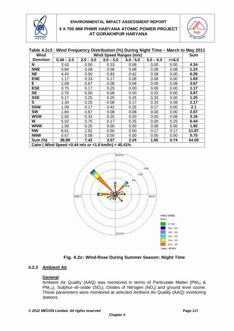
ENVIRONMENTAL IMPACT ASSESSMENT REPORT
4 X 700 MW PHWR HARYANA ATOMIC POWER PROJECT AT GORAKHPUR HARYANA
© 2012 MECON Limited. All rights reserved Page 117
Chapter 4
Table 4.2c3 : Wind Frequency Distribution (%) During Night Time – March to May 2011 Wind Speed Ranges (m/s) Wind
Direction 0.44 – 2.0 2.0 – 3.0 3.0 – 5.0 4.0 - 5.0 5.0 – 6.0 >=6.0 Sum
N 3.43 0.50 0.33 0.08 0.00 0.00 4.34 NNE 0.84 0.08 0.08 0.08 0.08 0.08 1.24 NE 4.43 0.50 0.83 0.42 0.08 0.00 6.26 ENE 1.17 0.33 0.17 0.08 0.08 0.00 1.83 E 2.68 0.67 0.08 0.08 0.08 0.08 3.67 ESE 0.75 0.17 0.25 0.00 0.00 0.00 1.17 SE 2.76 0.50 0.08 0.00 0.33 0.00 3.67 SSE 0.17 0.25 0.25 0.25 0.33 0.00 1.25 S 1.34 0.25 0.08 0.17 0.25 0.08 2.17 SSW 1.09 0.17 0.42 0.25 0.17 0.00 2.1 SW 1.84 0.67 0.08 0.08 0.00 0.00 2.67 WSW 2.50 0.33 0.25 0.00 0.00 0.08 3.16 W 5.02 0.75 0.17 0.25 0.00 0.25 6.44 WNW 1.59 0.25 0.00 0.00 0.08 0.00 1.92 NW 8.61 1.92 0.50 0.50 0.17 0.17 11.87 NNW 0.67 0.08 0.00 0.00 0.00 0.00 0.75 Sum (%) 38.89 7.42 3.57 2.24 1.65 0.74 54.59 Calm ( Wind Speed <0.44 m/s or <1.6 km/hr) = 45.41%
Fig. 4.2c: Wind-Rose During Summer Season: Night Time
4.2.2 Ambient Air General Ambient Air Quality (AAQ) was monitored in terms of Particulate Matter (PM10 & PM2.5), Sulphur–di–oxide (SO2), Oxides of Nitrogen (NOx) and ground level ozone. These parameters were monitored at selected Ambient Air Quality (AAQ) monitoring stations.

ENVIRONMENTAL IMPACT ASSESSMENT REPORT
4 X 700 MW PHWR HARYANA ATOMIC POWER PROJECT AT GORAKHPUR HARYANA
© 2012 MECON Limited. All rights reserved Page 118
Chapter 4
Selection of Monitoring Stations For locating the ambient air quality (AAQ) monitoring stations, the evaluation area may be considered a circle of radius 50 times the maximum stack height. Since the maximum stack height (ventilation stack) for the proposed project is 100m, the evaluation area is a circle of radius 5.0 km. However, as the project site is about 1.0 km radius circle drawn around each 700 MWe PHWR unit, so to have a conservative approach the monitoring stations has been fixed in a radius of 10 km around the proposed Plant taking Reactor Building as centre. To select the locations of the ambient air quality monitoring stations, information published by India Meteorological Department (IMD) was used. The IMD observatory nearest to plant site is at Hisar about 33 km SSE of the project site. As per Hisar IMD's data (Indian Meteorological Department observations from 1955 to 1980 – nearest observatory to the Project site), the annual temperature varies from varies from 41.0oC to 5.5oC and relative humidity varies from 27 - 82%. The annual average rainfall at Hisar is 490.6mm most of it occurs during monsoon. The annual and summer predominant wind directions are shown in Table 4.2d.
Table 4.2d: Pattern of Annual and Summer Winds in Study Area Wind N NE E SE S SW W NW Calm Annual % Frequency 10.5 6.5 8.5 8.5 5.0 12.5 17 13 17.5 Predominance Sequence 4th 6th 5th 5th 7th 3rd 1st 2nd Summer % Frequency 14.7 5.8 6.0 6.7 7.2 13.8 17.8 17.5 11.6 Predominance Sequence 3rd 8th 7th 6th 5th 4th 1st 2nd
The main objective of AAQ data generation / establishment of baseline for AAQ is to assess the future scenario of the surrounding environment by superimposing the predicted pollution levels on the existing pollution levels. Thus it will be possible to identify the location where maximum concentrations of pollutants are likely to occur due to emissions from the proposed plant. The predominant wind direction of nearest IMD observatory at Hisar was identified with the help of wind frequencies. The predominant annual wind frequencies are W (17%), NW (13%), SW (12.5%), N (10%) and E & SE (8.5%), while the calm value is 17.5%. The predominant wind frequencies during summer season are W (17.8%), NW (17.5%), SW (13.8), N (13.7) and S (9.2%), while the calm values are 11.6% (Table 4.2d). The locations of AAQ stations are given in Table 4.3a. The AAQ stations were located in the upwind and downwind direction of annual and summer winds with respect the proposed plant by considering the points mentioned below: 1. Location of AAQ stations within 10 km radius around the proposed plant. 2. Approachability to and habitation near the monitoring stations. 3. Location of other industries within 10 km radius around the proposed plant.

ENVIRONMENTAL IMPACT ASSESSMENT REPORT
4 X 700 MW PHWR HARYANA ATOMIC POWER PROJECT AT GORAKHPUR HARYANA
© 2012 MECON Limited. All rights reserved Page 119
Chapter 4
Table 4.3a: Location of AAQ Monitoring Stations Distance & Direction With Respect to Remarks Stat
-ion No.
Location Project
Site Relative Location With Respect to IMD Annual Wind Pattern
Relative Location With Respect to IMD Summer Wind Pattern
A1 Gorakhpur 3.5, E D/W of 1st predominant Annual wind W.
D/W of 1st predominant summer wind W.
Continuous
A2 Nehla 9.5 E D/W of 1st predominant Annual wind W.
D/W of 1st predominant summer wind W.
Continuous
A3 Siwani 5.5, SE D/W of 2nd predominant annual wind NW.
D/W of 2nd predominant summer wind NW.
Continuous
A4 Kirmara 9.0, SE D/W of 2nd predominant annual wind NW.
D/W of 2nd predominant summer wind NW.
Continuous
A5 Chaubara 5.5, NE D/W of 3rd most predominant annual wind SW
D/W of 4th most predominant summer wind SW
Continuous
A6 Sabarwas 5.0, S D/W of 4th predominant annual wind N.
D/W of 3rd predominant summer wind N.
Continuous
A7 Kajalheri 3, WSW
D/W of 5th predominant annual wind E.
D/W of 7th predominant summer wind E.
Continuous
A8 Khaujri 4.25, NNW
D/W of 7th predominant annual wind S.
D/W of 5th predominant summer wind S.
Continuous
Methodology As per the CPCB guidelines on methods of monitoring & analysis, 8 (eight) AAQ monitoring stations were selected. These stations are marked in Drg. No. MEC/11/S2/Q6SY/01. During the monitoring periods, 24 hourly samples were collected twice a week for PM10, SO2 and NOx, on each monitoring day. However as the site is a green field site, for PM2.5 24 hourly samples were collected on selected monitoring days. Eight hourly samples were collected on selected monitoring days for ozone. The methods of sample collection, equipment used and analysis procedure as followed are given in Table 4.3b. The AAQ results have been compared with MoEF Revised National ambient Air Quality Standards 2009 as given in Table 4.3c. The days on which monitoring was conducted at different AAQ stations is given in Table 4.3d. Table 4.3b: Methodology of Sampling and Analysis for AAQ Monitoring
Parameter Instrument/Apparatus Used
Methodology Reference
SO2 (µg/m3) HVAS with Impinger Tube, Spectro–photometer
Improved West & Gaecke Method
MoEF G.S.R 826 (E) dtd. 16.11.09
NOx (µg/m3) HVAS with Impinger Tube, Spectro–photometer
Jacobs & Hoccheiser Modified (Na-Arsenite) Method
-do-
PM10 (µg/m3) Respirable Dust Sampler Gravimetry -do- PM2.5 (µg/m3) PM 2.5 Sampler Gravimetry -do- Ozone (O3) (µg/m3) HVAS with Impinger Tube,
Spectro–photometer Chemical Method -do-

ENVIRONMENTAL IMPACT ASSESSMENT REPORT
4 X 700 MW PHWR HARYANA ATOMIC POWER PROJECT AT GORAKHPUR HARYANA
© 2012 MECON Limited. All rights reserved Page 120
Chapter 4
Table 4.3c: National Ambient Air Quality Standards Concentration in Ambient Air SN Parameter Time
Weighted Average
Industrial, Residential, Rural
& Other Areas
Ecologically Sensitive Area (Notified by
Central Government) Annual* 50 20 1 SO2 ; (µg/m3) 24 Hours** 80 80 Annual* 40 30 2 NOx ; (µg/m3) 24 Hours** 80 80 Annual* 60 60 3 PM10; (µg/m3) 24 Hours** 100 100 Annual* 40 40 4 PM2.5; (µg/m3) 24 Hours** 60 60 8 Hours ** 100 100 5 Ozone (O3); (µg/m3) 1 Hour ** 180 180
* Annual arithmetic mean of minimum 104 measurements in a year at a particular site taken twice a week 24 hourly at uniform intervals
** 24 hourly or 08 hourly or 01 hourly monitored values, as applicable, shall be compiled with 98% of the time in a year. 2% of the time, they may exceed the limits but not on two consecutive days.
Table 4.3d: Dates of AAQ Sampling During Summer Date of Sampling S
N Location
March’11 April’11 May’11 1 Gorakhpur A1 1 5 9 13 17 21 25 29 1 5 9 13 17 21 25 29 1 5 9 13 17 21 25 29 2 Nehla A2 1 5 9 13 17 21 25 29 1 5 9 13 17 21 25 29 1 5 9 13 17 21 25 29 3 Siwani A3 1 5 9 13 17 21 25 29 1 5 9 13 17 21 25 29 1 5 9 13 17 21 25 29 4 Kirmara A4 1 5 9 13 17 21 25 29 1 5 9 13 17 21 25 29 1 5 9 13 17 21 25 29 5 Chaubara A5 1 5 9 13 17 21 25 29 1 5 9 13 17 21 25 29 1 5 9 13 17 21 25 29 6 Sabarwas A6 1 5 9 13 17 21 25 29 1 5 9 13 17 21 25 29 1 5 9 13 17 21 25 29 7 Kajalheri A7 1 5 9 13 17 21 25 29 1 5 9 13 17 21 25 29 1 5 9 13 17 21 25 29 8 Khaujri A8 1 5 9 13 17 21 25 29 1 5 9 13 17 21 25 29 1 5 9 13 17 21 25 29
Results of Ambient Air Quality The summarised AAQ results are given in Table 4.3e and shown in Fig. 4.3a, 4.3b, 4.3c, 4.3d and 4.3e. The detailed AAQ results have been given in Annexure IVB. The results have been compared with MoEF Revised AAQ Standard 2009. The results of SO2, NOx, PM10, PM2.5 and O3 at all the monitoring stations are below the MoEF industrial, residential, rural & other area norms for the respective pollutants.
Table 4.3e: AAQ During Summer Parameters Gorakhpur
A1 Nehla
A2 Siwani
A3 Kirmara
A4 Chaubara
A5 Sabarwas
A6 Kajalheri
A7 Khaujri
A8 Max 15 14 20 18 12 13 14 11 Min. 5 4 4 4 5 4 5 5 Avg 9 7 10 9 8 8 9 7
SO2 (µg/m3)
C 98 15 12 19 17 12 13 14 11 Max 31 23 36 46 19 30 24 17 Min. 9 7 8 6 8 5 8 8 Avg 17 13 21 17 13 14 14 13
NOx (µg/m3)
C 98 29 20 36 40 19 27 23 17 Max 85 84 84 86 72 87 83 65 Min. 53 52 49 42 52 59 50 45
PM10 (µg/m3)
Avg 78 72 72 74 63 76 64 59

ENVIRONMENTAL IMPACT ASSESSMENT REPORT
4 X 700 MW PHWR HARYANA ATOMIC POWER PROJECT AT GORAKHPUR HARYANA
© 2012 MECON Limited. All rights reserved Page 121
Chapter 4
Parameters Gorakhpur A1
Nehla A2
Siwani A3
Kirmara A4
Chaubara A5
Sabarwas A6
Kajalheri A7
Khaujri A8
C 98 85 84 84 86 72 87 80 65 Max 49 49 46 48 46 49 48 44 Min. 22 29 28 25 29 29 29 30 Avg 37 41 39 41 35 43 38 38
PM2.5 (µg/m3)
C 98 48 49 46 47 44 49 47 44 Max 35 33 34 33 36 34 34 34 Min. 22 21 20 21 20 21 20 21 Avg 28 26 26 26 27 26 25 26
O3 (µg/m3)
C 98 35 33 33 33 36 34 33 33
0
10
20
30
40
50
60
70
80
90
Gor
akhp
ur A
1
Neh
la
A
2
Siw
ani
A
3
Kirm
ara
A
4
Cha
ubar
a A5
Saba
rwas
A6
Kaja
lher
i A7
Khau
jri
A8
AAQ Stations
SO2 (
µg/m
3 )
Max Min. Avg
SO2 Norm
Fig. 4.3a: SO2 Concentration in the Study Area
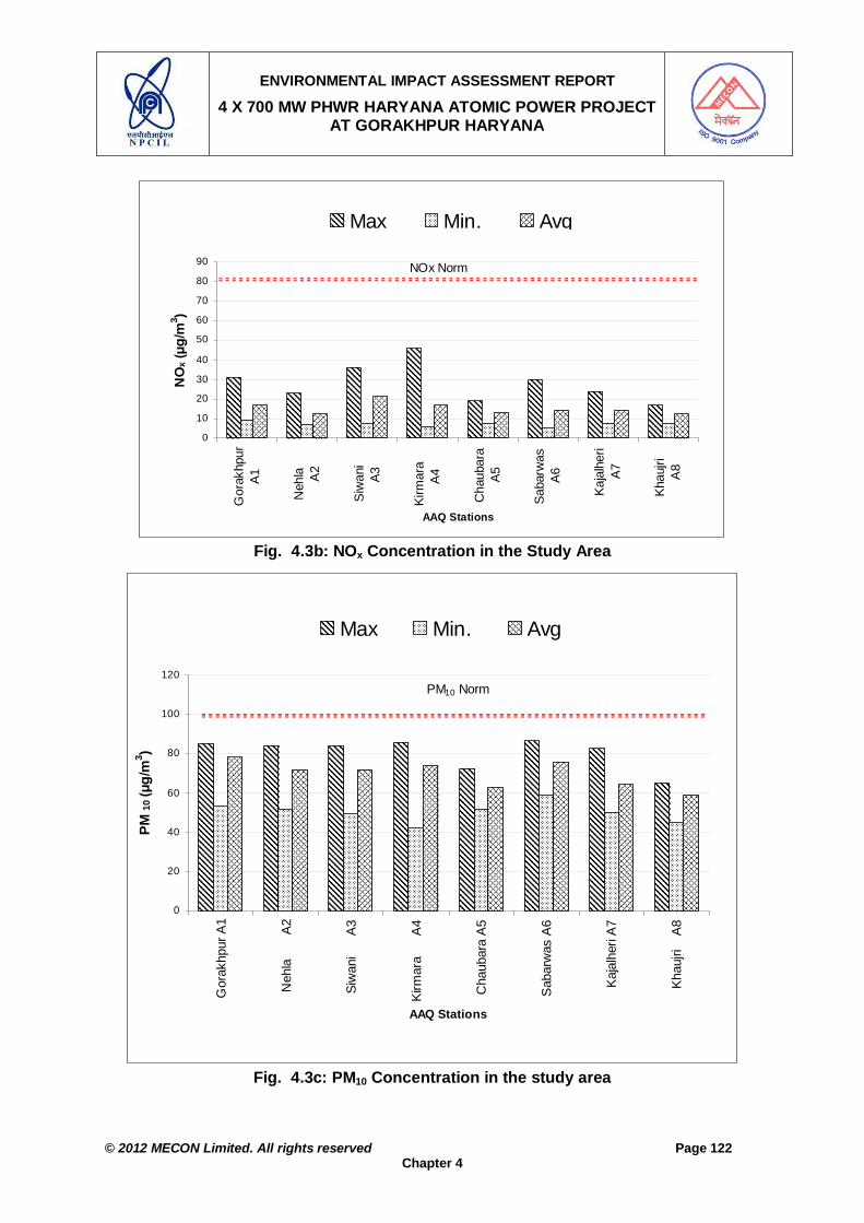
ENVIRONMENTAL IMPACT ASSESSMENT REPORT
4 X 700 MW PHWR HARYANA ATOMIC POWER PROJECT AT GORAKHPUR HARYANA
© 2012 MECON Limited. All rights reserved Page 122
Chapter 4
0
10
20
30
40
50
60
70
80
90
Gor
akhp
urA1
Neh
la
A
2
Siw
ani
A3
Kirm
ara
A4
Cha
ubar
aA5
Saba
rwas
A6
Kaja
lher
iA7
Khau
jri
A8
AAQ Stations
NO
x (µg
/m3 )
Max Min. Avg
NOx Norm
Fig. 4.3b: NOx Concentration in the Study Area
0
20
40
60
80
100
120
Gor
akhp
ur A
1
Neh
la
A
2
Siw
ani
A
3
Kirm
ara
A
4
Cha
ubar
a A
5
Sab
arw
as A
6
Kaj
alhe
ri A
7
Kha
ujri
A
8
AAQ Stations
PM 10
(µg/
m3 )
Max Min. Avg
PM10 Norm
Fig. 4.3c: PM10 Concentration in the study area

ENVIRONMENTAL IMPACT ASSESSMENT REPORT
4 X 700 MW PHWR HARYANA ATOMIC POWER PROJECT AT GORAKHPUR HARYANA
© 2012 MECON Limited. All rights reserved Page 123
Chapter 4
0
20
40
60
80
Gor
akhp
urA1
Neh
la
A2
Siw
ani
A
3
Kirm
ara
A4
Cha
ubar
aA
5
Sab
arw
asA
6
Kaj
alhe
riA7
Kha
ujri
A
8
AAQ Stations
PM 2.
5 (µg
/m3 )
Max Min. Avg
PM2.5 Norm
Fig. 4.3d: PM2.5 Concentration in the study area
0
20
40
60
80
100
120
Gor
akhp
urA
1
Neh
la
A
2
Siw
ani
A
3
Kirm
ara
A
4
Cha
ubar
aA
5
Sab
arw
asA
6
Kaj
alhe
riA
7
Kha
ujri
A
8
AAQ Stations
Ozo
ne (µ
g/m
3 )
Max Min. Avg
Ozone Norm
Fig. 4.3e: Ozone concentration in the study area
4.2.3 Noise
Selection of Monitoring Locations A total of ten noise monitoring stations were selected to cover all type of areas as given in Table 4.4a.

ENVIRONMENTAL IMPACT ASSESSMENT REPORT
4 X 700 MW PHWR HARYANA ATOMIC POWER PROJECT AT GORAKHPUR HARYANA
© 2012 MECON Limited. All rights reserved Page 124
Chapter 4
Table 4.4a: Noise Monitoring Locations Station
No. Location Distance w.r.t.
Site Centre (km) Direction w.r.t Site Centre
Type of Area* Date of Sampling
N1 Gorakhpur 3.5 E Commercial 14.04.11 N2 Nahla 9.5 E Residential Area 15.04.11 N3 Siwani 5.5 SE Residential Area 16.04.11 N4 Kirmara 9.0 SE Residential Area 17.04.11 N5 Chaubara 5.5 NE Residential Area 18.04.11 N6 Sabarwas 5.0 S Residential Area 19.04.11 N7 Kajalheri 3.0 WSW Residential Area 20.04.11 N8 Khaujari 4.25 NNW Residential Area 21.04.11 N9 Badopal Near NH 8.0 WSW National Highway
(Industrial Area) 22.04.11
N10 Project Site 0 E Project Site (Proposed Industry)
23.04.11
* Note: Type of area for representing Commercial, Residential & Industrial selected at site. NH 10 is taken as Industrial area.
Methodology To have an idea of the present background noise level of the project site, a detailed measurement of noise level was carried out at 10 locations during the monitoring period. Precision integrated sound level meter (type 2221 of Bruel & Kjaer of Denmark) was used for measurement of noise level for the study. The measurements were carried out for 24 hours. Hourly readings were recorded by the operating the instrument for 15–20 minutes in each hour at one-hour intervals in which leq(A) have been measured. The noise monitoring stations are marked in Drg. No. MEC/11/S2/Q6SY/01. Results The results of ambient noise monitoring are given in Table 4.4b and shown in Fig. 4.4a and 4.4b. The results have been compared with MoEF norms [Noise (Regulation & Control) Rules, 2000] given in Table 4.4c. The result shows that at Gorakhpur (N1) both day and night time noise is below the norm for commercial area. At Nahla (N2), Siwani (N3), Gorakhpur (Project Site) (N10) and Kirmara (N4) both day and night time noise values are within the norm for residential area. At NH near Badopal (Hisar to Sirsa) (N5), the noise levels are below the norm for industrial area both during day and night time.
Table 4.4b: Results of Noise Monitoring
Day (0600-2200 hr.) Night (2200-0600 hr.) Stn. No. Location Max. Min. Mean* Max Min Mean*
N1 Gorakhpur 63.7 53.4 60.1 55 51.2 41.8 N2 Nahla 54.2 42.9 50.8 45 43.6 41.8 N3 Siwani 54.5 40.5 49.7 45 43.7 38.2 N4 Kirmara 53.4 41.1 50 45 43.5 35.1 N5 Chaubara 53.8 41.8 50.1 45 44.4 38.4 N6 Sabarwas 53.5 44.2 51 45 43.8 38.7 N7 Kajalheri 53.5 40.1 49.4 45 43.6 37.4 N8 Khaujari 53.4 45.4 51 45 43.6 37.5 N9 Badopal 65.8 51.4 60.3 70 55.9 46.8 N10 Project Site 53.9 40.9 47.8 45 44.4 39.7 Day - 0600 to 2200 hrs.; Night - 2200 to 0600 hrs.; All values in dB(A); * Logarithmic Averages

ENVIRONMENTAL IMPACT ASSESSMENT REPORT
4 X 700 MW PHWR HARYANA ATOMIC POWER PROJECT AT GORAKHPUR HARYANA
© 2012 MECON Limited. All rights reserved Page 125
Chapter 4
Table 4.4c: Ambient Noise Level Norms Type of Area Day (0600-2200 hrs) Night (2200-0600 hrs) Industrial Area 75 70 Commercial Area 65 55 Residential Area 55 45 Silence zone 50 40 All values in dB (A)
Noise Levels During Day Time
05
101520253035404550556065707580
Gor
akhp
urN
1
Neh
la N
2
Siw
ani N
3
Kirm
ara
N4
Cha
ubar
aN
5
Sab
arw
asN
6
Kaj
alhe
riN
7
Kha
ujri
N8
Bad
opal
N9
Pro
ject
Site
N10
Noise Level Monitoring Stations
Noi
se L
evel
s dB
(A)
Norm dB (A) Max dB (A) Min. dB (A) Avg. dB (A)
Fig. 4.4a: Noise Levels During Day Time in the Study Area

ENVIRONMENTAL IMPACT ASSESSMENT REPORT
4 X 700 MW PHWR HARYANA ATOMIC POWER PROJECT AT GORAKHPUR HARYANA
© 2012 MECON Limited. All rights reserved Page 126
Chapter 4
Noise Levels During Night Time
05
101520253035404550556065707580
Gor
akhp
urN
1
Neh
la N
2
Siw
ani N
3
Kirm
ara
N4
Cha
ubar
aN
5
Sab
arw
asN
6
Kaj
alhe
riN
7
Kha
ujri
N8
Bad
opal
N9
Pro
ject
Site
N10
Noise Level Monitoring Stations
Noi
se L
evel
s dB
(A)
Norm dB (A) Max dB (A) Min. dB (A) Avg. dB (A)
Fig. 4.4b: Noise Levels During Night Time in the Study Area
4.2.4 Water Environment
Water quality monitoring was carried out with the following objectives: To collect baseline data on existing water quality. To assess the impact of the proposed outfalls on water quality of receiving
water bodies. To assess the raw water quality to be used by the proposed project.
Selection of Sampling Locations A total of eight water-sampling locations were selected for the present study covering four surface water and four ground water sampling locations. The Surface water sampling locations were selected at different locations all along the Canal up-stream and down-stream of project site keeping in view the confluence point of surface water channels receiving proposed plant outfalls. The canal water is being used by the villagers for bathing, washing and cattle washing. The ground water sampling locations were selected up gradient and down gradient of the different units of the proposed plant. These stations are marked in Drg. No. MEC/11/S2/Q6SY/01. Methodology In order to study the existing water quality within the study area, grab samples of water were collected from locations, as given in Table 4.5a. Surface water samples were analysed for different parameters as required by CPCB surface water criteria and ground water samples were analysed for different parameters as per IS: 10500. The water samples analysed for different parameters as per American Public Health Association (APHA), 1995 - "Standard Methods for the Examination of Water and Waste Water" and IS: 3205 (Part 39) 1990 (reaffirmed 1996).

ENVIRONMENTAL IMPACT ASSESSMENT REPORT
4 X 700 MW PHWR HARYANA ATOMIC POWER PROJECT AT GORAKHPUR HARYANA
© 2012 MECON Limited. All rights reserved Page 127
Chapter 4
Results of Surface Water Quality: The result of Surface Water quality is given in Tables 4.5b. The surface water quality was compared with CPCB norm for surface water, as given in Table 4.5c. The surface water quality is within the norms for Classes B, C, D, and E (Table 4.5c). The BOD levels in all the samples were also within the norm for Class B (3mg/l max.).
Table 4.5a: Location of Water Monitoring Station
Station / Sample
No.
Location Distance w.r.t. Site Centre (km)
Direction w.r.t Site Centre
Source Date of Sampling
Surface Water SW1 Bhakhra Canal Fatehabad
Branch (U/S of Project site) 2.5 NE Surface
Water (Canal) 28.04.11
SW2 Bhakhra Canal Fatehabad Branch (D/S of Project site)
1..0 NNE Surface Water (Canal)
28.04.11
SW3 Sirsa Branch Canal 3.0 WNW Surface Water (Canal)
28.04.11
SW4 Kishangarh Sub-branch Canal
2.5 W Surface Water (Canal)
28.04.11
Ground Water GW1 Gorakhpur 3.5 E Ground Water 28.04.11 GW2 Sabarwas 5.0 S Ground Water 28.04.11 GW3 Samani 5.5 SE Ground Water 28.04.11 GW4 Kajalheri 3.0 WSW Ground Water 28.04.11
Table 4.5b: Surface Water Quality
Surface Water Monitoring Location SN Parameters SW1 SW2 SW3 SW4
1. Colour, Hazen units, Max <5 10 <5 11 2. Turbidity, NTU, Max. 8 7 6 2 3. pH Value 8.4 8.4 8.6 8.4 4. Temp oC 25 26 26 25 5. Total suspended solid, mg/l, Max 19 12 24 22 6. Dissolved Oxygen (as O2), mg/l 5.8 5.9 5.5 5.2 7. BOD, 5 days at 20 C, mg/l 2.7 2.5 2.5 2.7 8. Electrical conductivity, mhos/cm, Max 638 710 774 720 9. Iron (as Fe), mg/l, Max 0.26 0.22 0.17 0.43 10. Chloride (as Cl), mg/l, Max 67 64 16 12 11. Fluoride (as F) mg/l, Max 0.81 0.80 0.67 0.64 12. Copper (Cu), mg/l, Max <0.01 <0.01 <0.01 <0.01 13. Manganese (as Mn), mg/l, Max 0.02 <0.01 0.044 0.042 14. Sulphate (as SO4), mg/l, Max 88 115 68 84 15. Nitrate,(as NO3), mg/l, Max 2.1 2.1 2.1 2.1 16. Phenolic Compounds (as C6 H5OH), mg/l Max. <0.001 <0.001 <0.001 <0.001 17. Cadmium (as Cd), mg/l, Max. <0.005 <0.005 <0.005 <0.005 18. Selenium (as Se), mg/l, Max. <0.005 <0.005 <0.005 <0.005 19. Arsenic (as As), mg/l, Max. <0.03 <0.03 <0.03 <0.03 20. Cyanide (as CN), mg/l, Max. <0.01 <0.01 <0.01 <0.01 21. Lead (as Pb), mg/l, Max. <0.05 <0.05 <0.05 <0.05 22. Zinc (as Zn), mg/l, Max. 0.26 0.15 0.12 0.15 23. Anionic detergent (MBAS) mg/l, Max <0.03 <0.03 <0.03 <0.03 24. Hexavalent Chromium (as Cr6 +), mg/l, Max. <0.01 <0.01 <0.01 <0.01 25. Oil & Grease mg/l, Max. <0.1 <0.1 <0.1 <0.1
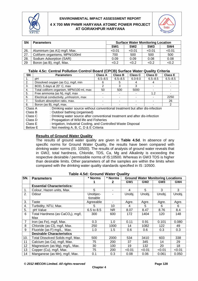
ENVIRONMENTAL IMPACT ASSESSMENT REPORT
4 X 700 MW PHWR HARYANA ATOMIC POWER PROJECT AT GORAKHPUR HARYANA
© 2012 MECON Limited. All rights reserved Page 128
Chapter 4
Surface Water Monitoring Location SN Parameters SW1 SW2 SW3 SW4
26. Aluminium (as A1) mg/l, Max. <0.01 <0.01 <0.01 <0.01 27. Coliform organisms, MPN/100ml 700 500 500 500 28. Sodium Adsorption (SAR) 0.09 0.09 0.08 0.08 29 Boron (as B), mg/l, Max. <0.2 <0.2 <0.2 <0.2
Table 4.5c: Central Pollution Control Board (CPCB) Surface Water Quality Criteria
SN Parameters Class A Class B Class C Class D Class E 1. pH 6.5–8.5 6.5–8.5 6.0-9.0 6.5–8.5 6.5–8.5 2. Dissolved oxygen (as O2), mg/l, min 6 5 4 4 - 3. BOD, 5 days at 20 C, max 2 3 3 - - 4. Total coliform organism, MPN/100 ml, max 50 500 5000 - - 5. Free ammonia (as N), mg/l, max - - - 1.2 - 6. Electrical conductivity, mhos/cm, max - - - - 2250 7. Sodium absorption ratio, max. - - - - 26 8. Boron (as B), mg/l, max. - - - - 2 Class A : Drinking water source without conventional treatment but after dis-infection Class B : Outdoor bathing (organised) Class C : Drinking water source after conventional treatment and after dis-infection Class D : Propagation of Wild life and Fisheries Class E : Irrigation, Industrial Cooling, and Controlled Waste Disposal Below E : Not meeting A, B, C, D & E Criteria
Results of Ground Water Quality The results of ground water quality are given in Table 4.5d. In absence of any specific norms for Ground Water Quality, the results have been compared with drinking water norms (IS: 10500). The results of analysis of ground water reveals that in GW2, total hardness, Chloride, TDS, Ca, Mg and Alkalinity is exceeding the respective desirable / permissible norms of IS:10500. Whereas in GW3 TDS is higher than desirable limits. Other parameters of all the samples are within the limits when compared with the drinking water quality standards specified in IS :10500.
Table 4.5d: Ground Water Quality Ground Water Monitoring Locations SN. Parameters * Norms
1 * Norms
2 GW1 GW2 GW3 GW4 Essential Characteristics:
1. Colour, Hazen units, Max. 5 - 4 5 3 3 2. Odour Unobjec-
tionable - Unobj. Unobj. Unobj. Unobj.
3. Taste Agreeable - Agre. Agre. Agre. Agre. 4. Turbidity, NTU, Max. 5 10 4 5 6 6 5. pH Value 6.5 to 8.5 NR 8.07 8.47 8.76 8.4 6 Total Hardness (as CaCO3), mg/l,
Max 300 600 172 1404 120 148
7 Iron (as Fe), mg/l, Max. 0.3 1.0 0.11 0.91 0.101 0.080 8 Chloride (as Cl), mg/l, Max. 250 1000 14 1082 122 49 9 Fluoride (as F) mg/L, Max. 1.0 1.5 0.6 0.6 0.3 0.3 Desirable Characteristics
10. Total Dissolved Solids mg/l, Max. 500 2000 534 3410 603 338 11 Calcium (as Ca), mg/l, Max. 75 200 37 345 14 29 12 Magnesium (as Mg), mg/L, Max. 30 100 19 132 20 18 13 Copper (Cu), mg/l, Max. 75 200 <0.01 <0.01 <0.01 <0.01 14 Manganese (as Mn), mg/l, Max. 0.1 0.3 0.08 0.06 0.061 0.050

ENVIRONMENTAL IMPACT ASSESSMENT REPORT
4 X 700 MW PHWR HARYANA ATOMIC POWER PROJECT AT GORAKHPUR HARYANA
© 2012 MECON Limited. All rights reserved Page 129
Chapter 4
Ground Water Monitoring Locations SN. Parameters * Norms 1
* Norms 2 GW1 GW2 GW3 GW4
15 Sulphate (as SO4), mg/l, Max. 200 400 124 464 133 63 16 Nitrate (as NO3), mg/l, Max. 45 100 14 11 14 13 17 Phenols (as C6 H5OH), mg/l,Max 0.001 0.005 <0.001 <0.001 <0.001 <0.001 18. Mercury (as Hg), mg/l, Max. 0.001 NR <0.0005 <0.0005 <0.0005 <0.0005 19 Cadmium (as Cd), mg/l, Max. 0.01 NR <0.005 <0.005 <0.005 <0.005 20. Selenium (as Se), mg/l, Max. 0.01 NR <0.005 <0.005 <0.005 <0.005 21. Arsenic (as As), mg/l, Max. 0.05 NR <0.03 <0.03 <0.03 <0.03 22. Cyanide (as CN), mg/l, Max. 0.05 NR <0.01 <0.01 <0.01 <0.01 23. Lead (as Pb), mg/l, Max. 0.05 NR <0.05 <0.05 <0.05 <0.05 24. Zinc (as Zn), mg/l, Max. 5.0 15 0.038 0.045 0.167 0.107 25. Anionic detergent (as MBAS)
mg/l, Max 0.2 1.0 <0.1 <0.1 <0.1 <0.1
26 Hexavalent Chromium (as Cr6+), mg/l
0.01 NR <0.01 <0.01 <0.01 <0.01
27. Mineral Oil, mg/l, Max. 0.01 0.03 <1.4 <1.4 <2 <2 28 Alkalinity (as CaCO3) mg/l, Max. 200 600 150 232 102 116 29. Aluminium (as A1) mg/l, Max. 0.03 0.2 <0.01 <0.01 <0.01 <0.01 30 Boron, mg/l, Max. 1.0 5 <0.2 <0.2 <0.2 <0.2 * Norms as per Drinking Water – Specification - IS: 10500 (1991) and amendment no. 1, 1993
1. Requirement (desirable limits); 2.Permissible limits in the absence of alternate source; NR: No Relaxation
4.2.5 Soil
Selection of Sampling Location The soil sampling locations were selected with the following objectives: To assess the background / baseline soil quality of the region. To assess the impact (if any) of proposed Plant air emissions, effluent outfall
and solid waste on soil of the study area. A total of ten sampling locations as marked in Drg. No. MEC/11/S2/Q6SY/01, were selected for the study. The selected locations and the justification for their selection are given in Table 4.6a.
Table 4.6a: Selection of Soil Sampling Locations and Justification
Station / Sample No.
Location Distance w.r.t. Site Centre (km)
Direction w.r.t Site Centre
Type of Land
Date of Sampling
S1 Gorakhpur 3.5 E Agriculture 26.11.10 S2 Nahla 9.5 E Agriculture 26.11.10 S3 Samani 5.5 SE Agriculture 26.11.10 S4 Kirmara 9.0 SE Agriculture 26.11.10 S5 Chaubara 5.5 NE Agriculture 26.11.10 S6 Sabarwas 5.0 S Agriculture 26.11.10 S7 Kajalheri 3.0 WSW Agriculture 26.11.10 S8 Khaujari 4.25 NNW Agriculture 26.11.10 S9 Badopal 8.0 WSW Agriculture 26.11.10 S10 Project Site 0 - Agriculture 26.11.10

ENVIRONMENTAL IMPACT ASSESSMENT REPORT
4 X 700 MW PHWR HARYANA ATOMIC POWER PROJECT AT GORAKHPUR HARYANA
© 2012 MECON Limited. All rights reserved Page 130
Chapter 4
Methodology In order to have an idea about the baseline soil quality in the study area, samples of topsoil were collected from the five locations once during the study period. The soil samples were marked, brought to laboratory, air-dried and analysed for different physico-chemical characteristics by following the methodology given in Jackson, M.L. (1967): "Soil Chemical Analysis" (Prentice Hall of India Pvt. Limited, New Delhi) and "Soil Test Methodology" (1992), Edited B.S. Mathur. SSAC (BAU) Tech. Bull. 3/92. Pp. 312. Department of Soil Sciences and Agriculture Chemistry, Birsa Agriculture University, Ranchi. Results of Soil Analysis The results of analysis are given in Tables 4.6b, 4.6c, 4.6d and 4.6e. Soil pH plays a very important role in the availability of nutrients. The composition of the soil microbial community is also dependent on the soil pH. In the study area the soil samples had more or less neutral pH. . Electrical conductivity is a measure of the concentration of soluble salts and ionic activity. Salt concentration is directly proportional to the osmotic pressure, which governs the process of osmosis in the soil – plant system. The electrical conductivity in all the soil samples ranged from 0.075 mS/cm (S9) to 0.488 mS/cm (S4).
Table 4.6b: Physico-Chemical Properties of Soils
Results Characteristics S1 S2 S3 S4 S5 S6 S7 S8 S9 S10
Type of Land Agr. Agr. Agr. Agr. Agr. Agr. Agr. Agr. Agr. Agr. Colour Bl.
White Lgt Brw
Lgt Brw
Ylw White
Ylw White
Brw Ylw
Brw Ylw
Ylw White
Ylw White
Bl. White
Texture (Soil type)
S. Lm Lm. Sand
S. Lm S. Lm Sdy Sdy Sdy Sdy Lm. Sand
S. Lm
Bulk Density (gm/cc)
134 140 143 138 138 139 127 128 134 135
Water Holding Capacity (%)
32.4 32.5 29.7 29.8 31.1 32.1 30.1 32.3 30.5 30.1
pH (1:5 ratio) 7.0 6.9 7.1 6.8 7.0 7.2 6.9 7.3 6.8 6.8 Electrical Conductivity (mS/cm)
0.271 0.235 0.114 0.488 0.110 0.178 0.081 0.241 0.075 0.078
Phosphorus and Nitrogen are limiting nutrients. In the tested soil samples, availability of Nitrogen is Medium (in S1, S5, S6, S7, S8, S9 & S10) to high (S2, S3, & S4) and available Phosphorus is low in all the collected soil samples. However, Potassium is high in all the soil samples. Organic carbon content is medium (S1, S2, S6 and S8) to low (S3, S4, S5, S7, S9 & S10) in the soil samples.
Table 4.6c: Available Major Nutrients in Soil
Results Nutrients & Ratings S1 S2 S3 S4 S5 S6 S7 S8 S9 S10
Organic Carbon (%) 0.71M
0.57M
0.49 L
0.47 L
0.47 L
0.57 M
0.38 L
0.59 M
0.44 L
0.45 L
Organic Matter (%) 1.6 1.4 1.2 1.2 1.2 1.4 1.0 1.4 1.1 1.2 Available Nitrogen (kg/ha)
364 M
1254 H
583 H
715 H
383 M
301 M
326 M
320 M
354 M
351 M

ENVIRONMENTAL IMPACT ASSESSMENT REPORT
4 X 700 MW PHWR HARYANA ATOMIC POWER PROJECT AT GORAKHPUR HARYANA
© 2012 MECON Limited. All rights reserved Page 131
Chapter 4
Results Nutrients & Ratings S1 S2 S3 S4 S5 S6 S7 S8 S9 S10
Available Phosphorus (kg/ha)
2.0 L
1.0 L
2.0 L
0.2 L
2.0 L
1.0 L
1.0 L
1.0 L
1.0 L
1.0 L
Available Potassium (kg/ha)
709H
672 H
560 H
597 H
299 H
1289 H
373 H
336 H
336 H
373 H
Ratings: Organic Carbon : <0.50 – Low; 0.50 to 0.75 – Medium; >0.75 – High Available Nitrogen : <280 – Low; 280 to 560 – Medium; >560 – High Available Phosphorus : <10 – Low; 10 to 25 – Medium; >25 – High Available Potassium : <120 – Low; 120 to 280 – Medium; >280 – High
The results show that the Calcium and Magnesium constitutes the bulk of exchangeable cations in the tested soil samples. This indicates that the collected soil samples are showing the signs of increase in alkalinity (Sodium / Potassium).
Table 4.6d: Exchangeable Cations Results Cations
S1 S2 S3 S4 S5 S6 S7 S8 S9 S10 Calcium (meq/100gm)
12 (47.21)
8 (33.59)
4 (27.03)
8 (38.55)
4 (26.44)
24 (52.79)
32 (68.82)
26 (63.55)
4 (23.77)
4 (23.95)
Magnesium (meq/100gm)
12 (47.21)
14 (58.77)
10 (67.57)
8 (38.55)
10 (66.09)
20 (43.99)
14 (30.11)
14 (34.22)
12 (71.30)
12 (71.86)
Sodium (meq/100gm)
0.87 (3.42)
1.3 (5.46)
0.35 (2.36)
4.29 (20.67)
0.89 (5.88)
0.53 (1.17)
0.2 (0.43)
0.49 (1.20)
0.51 (3.03)
0.38 (2.28)
Potassium (meq/100gm)
0.55 (2.16)
0.52 (2.18)
0.45 (3.04)
0.46 (2.22)
0.24 (1.59)
0.93 (2.05)
0.3 (0.65)
0.42 (1.03)
0.32 (1.90)
0.32 (1.92)
Total base
25.42 (100)
23.82 (100)
14.8 (100)
20.75 (100)
15.13 (100)
45.46 (100)
46.5 (100)
40.91 (100)
16.83 (100)
16.7 (100)
Values in ( ) give the % of respective cation of the total cations.
Soil micro–nutrients also play an important role in plant growth and can act as limiting nutrients. Soil micro–nutrient analysis can be employed as a diagnostic tool for predicting the possibility of deficiency of a nutrient and the profitability of its application. For this it is necessary to fix the critical limits. The critical limit of a micro–nutrient is that content of extractable nutrient at or below which plantation practised on it will produce a positive response to its application. Copper and Zinc is high in all the tested soil samples. Iron is above the critical limits in all the soils samples. Since in the study area, the level of some micro–nutrients are above the critical limits and thus are in available amount and may prove helpful to plant growth. However it must be noted that very high concentrations of one or more micro–nutrients may be detrimental to plant growth and soil fertility may be adversely affected.
Table 4.6e: Available Micronutrients
Results Micro Nutrient S1 S2 S3 S4 S5 S6 S7 S8 S9 S10
Iron (as Fe) 0.48 0.31 0.3 0.41 0.4 0.32 0.37 0.31 0.41 0.47 Copper (as Cu) 0.61 0.52 0.57 0.61 0.64 0.51 0.42 0.52 0.49 0.58 Zinc (Zn) 4.9 5.6 5.5 5.7 5.9 4.8 4.3 4.6 5.1 4.8 Manganese (Mn) 2.4 2.7 2.5 2.7 3.4 3.8 3.5 2.9 3.6 2.5
Critical Limits (mg/kg) Iron 4.5 – 6.0 Copper 0.20 – 0.66 Zn 0.50 – 0.65

ENVIRONMENTAL IMPACT ASSESSMENT REPORT
4 X 700 MW PHWR HARYANA ATOMIC POWER PROJECT AT GORAKHPUR HARYANA
© 2012 MECON Limited. All rights reserved Page 132
Chapter 4
4.2.6 Ecological Features Objectives of the study The present study was undertaken with the following objectives: To assess the nature and distribution of vegetation in and around the project
site within the study area; To assess the type of faunal species within the study area; To assess the biodiversity of natural system present in the study area; To ascertain migratory routes of fauna and possibility of breeding grounds
within the study area; To assess the trophic status of the water bodies present in the study area.
Methodology of the Ecology Study The study area taken for the study is 10 km radius with the project site as center. The different methods adopted were as follows: Inventorisation of flora / fauna: The list of Flora and Fauna found in the Forest
Division (Fatehabad) was collected from the Working Plan of the division for reference. The list of flora and fauna found in the region was prepared by conducting field survey and by discussions with concerned Forest Department personnel using the list available in the Working Plan as a base.
Generation of primary data through systematic ecological studies: The phyto-sociology of the vegetation (covering frequency, density, abundance and species diversity) in the forest areas falling in the study area was to be determined by conducting field studies in selected areas (by laying suitable sizes of quadrat). Since there are no forests in the study area, only inventorisation of flora and fauna was done.
Discussion with local people so as to elicit information about local plant, animals and their uses and Gathering data for ethnobiology.
The present study is based on field studies conducted during winter season September to November 2011. The study area falls under the category of tropical desert thorn and comprise predominantly of xerophytes. The area is sparsely populated and is almost plain. The study area contains plantations around villages. There is no wildlife and bird sanctuary within the study area. The biotic environment can be described under following heads:
1. Project Site 2. Study Area: The study area can further be described as per the type of land use.
i) Agricultural land ii) Plantations around Human Settlements iii) Waste land iv) Faunal and avi-fauna v) Water Bodies
Project Site The project site as of now is barren or agricultural land. The waste land is without any vegetation and only sparsely scattered plants of Leonotis sp., Lantana sp., Calotropis spp, Croton sp., Zyziphus sp., Xanthium Straumarium, etc are growing. There is no forest land involved within the project site. The project area is predominantly double crop agriculture land. The details of Rabi and Kharif crops, cultivation area along with yield per ha is given in Table 4.7a.

ENVIRONMENTAL IMPACT ASSESSMENT REPORT
4 X 700 MW PHWR HARYANA ATOMIC POWER PROJECT AT GORAKHPUR HARYANA
© 2012 MECON Limited. All rights reserved Page 133
Chapter 4
Table 4.7a: Status of Agriculture at the Project Site SN. Crop Area (ha) Yield Kg/ha) Rabi 1 Wheat 463.4 4920 2 Gram 4.76 980 3 Mustard 32.80 1680 Kharif 4 Bajra 307.8 3040 5 Cotton 154 973 6 Paddy 39.2 3020
In between the agricultural fields, at the bund of the plots trees have been planted in scattered manner. There are about 1027 Eucalyptus spp trees growing in the project site, out of which the plant area located in the central part of the project area contains 575 trees. Study Area The study area is almost plain in topography. The plain areas are best utilized for cultivation during kharif and rabi seasons. Tree species found in cultivated fields, waste lands and habitations are Jand, Rohera, Khairi, Beri, Reru, Jal Or Van, Barh, Peepal, Mesquite or Pahari Kikar, Kachnar, Amaltas, Lasura, Imli, Banna, etc. Shisham, Kikar, Siris, Neem, Bakain Gultmohar. Parkinsonia Eucalyptus, etc. have been planted along rail, road and canal strips and in other private areas. Eucalyptus is also planted in agricultural and under farm forestry scheme. The Jand, Farash, Khairi, Castor, kana and Ruhera have been planted to check soil erosion by high velocity winds. Common shrubs found are Hins, Bansa, Panwar, Babool, Karir, Phoa, Khip and Ak. Medicinal herbs found in the district are Bansa, Indirain, Asgandha, Glo, Kharuthi, Bhakhra, Dhatura, etc. Their collection becomes uneconomical because these are available in scattered form. The important grasses found in the district are Anjan, Dhamang, Dub, Kana and Dabh. Anjan, Dhaman and Dub which are palatable fodder grasses are dwindling on account of uncontrolled grazing. The grasses in waste, lands are poor in quality and quantity. The plant species commonly found in the study area is given in Table 4.7b. The authenticated list of flora and fauna found in the study area is given in Annexure IVC.
Table 4.7b: List of Plants Growing in Study Area
SN. Common Names
Botanical Names Family Habbit Remarks
1. Babool Acacia jacquemontii Fabaceae Shrubs 2. Reru Acacia leucophloea Mimosaceae Trees 3. Kikar Acacia nilotica Mimosaceae Trees 4. Khairi Acacia senegal Mimosaceae Trees 5. Bansa Adhatoda Vasica Acanthaceae Herbs Medicinal 6. Unchti Ageratum conyzoides Asteraceae Herbs Medicinal 7. Pahari Neem Ailanthus excelsa Simaroubaceae Trees 8. Siris Albizia lebbeck Mimosaceae Trees 9. Kala Siris Albiziz odoratissima Mimosaceae Trees 10. Safed Siris Albizzia procera Mimosaceae Trees

ENVIRONMENTAL IMPACT ASSESSMENT REPORT
4 X 700 MW PHWR HARYANA ATOMIC POWER PROJECT AT GORAKHPUR HARYANA
© 2012 MECON Limited. All rights reserved Page 134
Chapter 4
SN. Common Names
Botanical Names Family Habbit Remarks
11. Dhinkwar Aloe barbeadensis Xanthorrhoeaceae Shrubs Medicinal 12. Gwarpatha Aloe vera Xanthorrhoeaceae Shrubs Medicinal 13. Chattin Alstonia scholaris Apocynaceae Trees 14. Kalmegh Andrographis paniculata Acanthaceae Herbs Medicinal 15. Sita Phal Annona squamosa Annonaceae Shrubs 16. Kadamb Anthocephalus cadamba Rubiaceae Trees 17. Brhamadandi Argemone maxicana Papaveraceae Shrubs Medicinal 18. Shatawar Asparagus racemosus Asparagaceae Shrubs Medicinal 19. Neem Azadirachta indica Meliaceae Trees Medicinal 20. Safed Kachnar Bauhinia verigata Caesalpiniaceae Trees 21. Semal Bombax ceiba Malvaceae Trees 22. Dhak Butea monosperma Fabaceae Trees 23. Phoa Calligonum
polygonoides Polygonaceae Shrubs
24. Ak Calotropis procera Asclepiadaceae Shrubs Medicinal 25. Bhang Cannabis sativa Cannabaceae Herbs Medicinal 26. Karir Capparis decidua Capparaceae Shrubs 27. Karaunda Carissa carandus Apocynaceae Shrubs 28. Hins Carissa spinarum Apocynaceae Shrubs 29. Amaltas Cassia fistula Caesalpiniaceae Trees 30. Panwar Cassia occidentalis Fabaceae Shrubs 31. Panwar Cassia tora Caesalpiniaceae Shrubs Medicinal 32. Sadabahar Catharanthus roseus Apocynacae Herbs Medicinal 33. Anjan Cenchrus ciliaris Poaceae Grasses 34. Dhamanq Cenchrus setigerus Poaceae Grasses 35. Indirain Citrullus colocynthis Cucurbitaceae Herbs Medicinal 36. Neebu Citrus medica Rutaceae Shrubs 37. Lasura Cordia dichotoma Boraginaceae Trees 38. Chota Lasora Cordia myxa Boraginaceae Trees 39. Banna Crataeva adansonii Capparaceae Trees 40. Amarbel Cuscuta reflexa Convolvulaceae Parasitic
Plant
41. Dub Cynodon dactylon Poaceae Grasses 42. Motha Cyperus scariosus Cyperaceae Grasses 43. Shisham Dalbergia sissoo Papilionaceae Trees 44. Dhatura Datura stramonium Solanaceae Herbs Medicinal 45. Gulmohar Delonix regia Caesalpiniaceae Trees 46. Dabh Desmostachya bipinnata Poaceae Grasses 47. Kala Dhatura Dhatura metal Solanaceae Shrubs Medicinal 48. Duranta Duranta repens Verbenaceae Shrubs 49. Eucalyptus Eucalyptus hybrid Myrtaceae Trees 50. Barh Ficus benghalensis Moraceae Trees 51. Gular Ficus glomerata Moraceae Trees 52. Peepal Ficus religiosa Moraceae Trees 53. Gudhal Hibiscus rosa-sinensis Malvaceae Shrubs 54. Khip Leptadenia pyrotechnica Asclepiadoideae Shrubs 55. Subabool Leucaena leucocephala Fabaceae Trees 56. Bakain Melia azedarach Meliaceae Trees Medicinal 57. Lajvanti Mimosa pudica Fabaceae Herbs Medicinal 58. Saijan Moringa oleifera Moringaceae Trees Medicinal 59. Shahtut Morus indica Moraceae Trees 60. Kela Musa sapientum Musaceae Shrubs
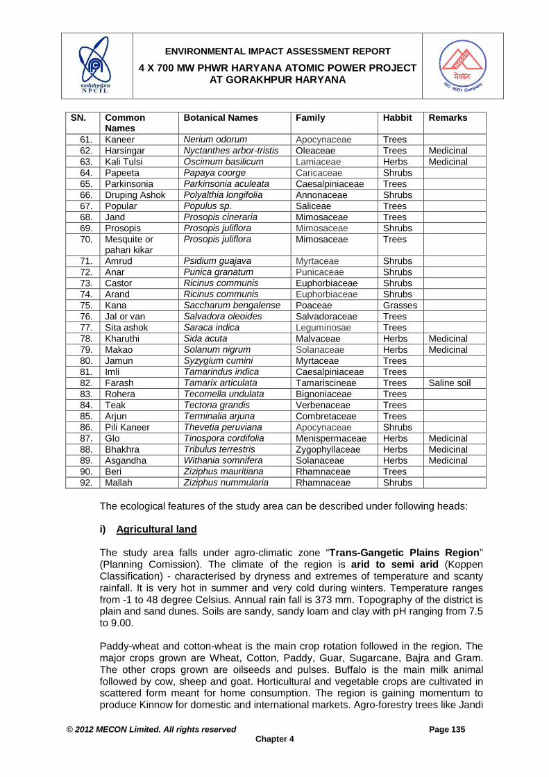
ENVIRONMENTAL IMPACT ASSESSMENT REPORT
4 X 700 MW PHWR HARYANA ATOMIC POWER PROJECT AT GORAKHPUR HARYANA
© 2012 MECON Limited. All rights reserved Page 135
Chapter 4
SN. Common Names
Botanical Names Family Habbit Remarks
61. Kaneer Nerium odorum Apocynaceae Trees 62. Harsingar Nyctanthes arbor-tristis Oleaceae Trees Medicinal 63. Kali Tulsi Oscimum basilicum Lamiaceae Herbs Medicinal 64. Papeeta Papaya coorge Caricaceae Shrubs 65. Parkinsonia Parkinsonia aculeata Caesalpiniaceae Trees 66. Druping Ashok Polyalthia longifolia Annonaceae Shrubs 67. Popular Populus sp. Saliceae Trees 68. Jand Prosopis cineraria Mimosaceae Trees 69. Prosopis Prosopis juliflora Mimosaceae Shrubs 70. Mesquite or
pahari kikar Prosopis juliflora Mimosaceae Trees
71. Amrud Psidium guajava Myrtaceae Shrubs 72. Anar Punica granatum Punicaceae Shrubs 73. Castor Ricinus communis Euphorbiaceae Shrubs 74. Arand Ricinus communis Euphorbiaceae Shrubs 75. Kana Saccharum bengalense Poaceae Grasses 76. Jal or van Salvadora oleoides Salvadoraceae Trees 77. Sita ashok Saraca indica Leguminosae Trees 78. Kharuthi Sida acuta Malvaceae Herbs Medicinal 79. Makao Solanum nigrum Solanaceae Herbs Medicinal 80. Jamun Syzygium cumini Myrtaceae Trees 81. Imli Tamarindus indica Caesalpiniaceae Trees 82. Farash Tamarix articulata Tamariscineae Trees Saline soil 83. Rohera Tecomella undulata Bignoniaceae Trees 84. Teak Tectona grandis Verbenaceae Trees 85. Arjun Terminalia arjuna Combretaceae Trees 86. Pili Kaneer Thevetia peruviana Apocynaceae Shrubs 87. Glo Tinospora cordifolia Menispermaceae Herbs Medicinal 88. Bhakhra Tribulus terrestris Zygophyllaceae Herbs Medicinal 89. Asgandha Withania somnifera Solanaceae Herbs Medicinal 90. Beri Ziziphus mauritiana Rhamnaceae Trees 92. Mallah Ziziphus nummularia Rhamnaceae Shrubs
The ecological features of the study area can be described under following heads:
i) Agricultural land The study area falls under agro-climatic zone “Trans-Gangetic Plains Region” (Planning Comission). The climate of the region is arid to semi arid (Koppen Classification) - characterised by dryness and extremes of temperature and scanty rainfall. It is very hot in summer and very cold during winters. Temperature ranges from -1 to 48 degree Celsius. Annual rain fall is 373 mm. Topography of the district is plain and sand dunes. Soils are sandy, sandy loam and clay with pH ranging from 7.5 to 9.00.
Paddy-wheat and cotton-wheat is the main crop rotation followed in the region. The major crops grown are Wheat, Cotton, Paddy, Guar, Sugarcane, Bajra and Gram. The other crops grown are oilseeds and pulses. Buffalo is the main milk animal followed by cow, sheep and goat. Horticultural and vegetable crops are cultivated in scattered form meant for home consumption. The region is gaining momentum to produce Kinnow for domestic and international markets. Agro-forestry trees like Jandi

ENVIRONMENTAL IMPACT ASSESSMENT REPORT
4 X 700 MW PHWR HARYANA ATOMIC POWER PROJECT AT GORAKHPUR HARYANA
© 2012 MECON Limited. All rights reserved Page 136
Chapter 4
is a part and parcel of farming system since time memorial. District Fatehabad is having nearly 92 percent of its area under irrigation by both the canal as well as the tube wells. The crop productivity in the area is given in Table 4.7c.
Table 4.7c : Average Productivity of Crops in the Region SN. Kharif Crop (July - Sept) Productivity (q/ha.) 1 Paddy 43.54 2 Sugarcane 76.04 Rabi Crop (Dec. - April) 1 Wheat 46.46 2 Jwar 37.15 3 Bajara 23.57. 4 Gram 12.65 5 Mustard, Taramira & Toria 14.73 6 Cotton 7.63
ii) Plantations around Human Settlements Near the villages, the vegetation pattern abruptly changes from that in the agricultural fields. The species commonly found are given in Table 4.7d. The trees commonly grown are mostly of economic importance. Among the fruit trees, which are common are Mango, Guava, Ber, Neebu, Banana, Papaya, etc. Among the non-fruit trees the common ones are Neem, Karanj, etc.
Table 4.7d: List of Common Trees/Shrubs Growing in and Around Human Settlement
SN Scientific Name Common Name 1 Albezzia lebbeck Siris 2 Annona squamosa Sita Phal 3 Azadirchta indica Neem 4 Bougainvellea spectabilis Bougainvellea 5 Carica papaya Papita 6 Citrus lemon Nimbu 7 Delonix regia Gulmohar 8 Eucalyptus hybrid Eucalyptus 9 Ficus bengalensis Bargad 10 Ficus religiosa Peepal 11 Mangifera indica Mango 12 Moringa oleifera Saijan 13 Musa sapientum Kela 14 Pongamia pinnata Karanj 15 Tamarindus indica Imli 16 Zyziphus sp. Ber 17 Embelica officinalis Aonla / Amloki 18 Psidium guajava Amrud 19 Polyalthia longifolia Ashok 20 Ricinus communis Rendi
iii) Waste land Wasteland has developed in the area where the soil conditions are poor and under high biotic pressure. Places where soil conditions are not appropriate to support plant growth are commonly seen in the area. All such areas are either without any vegetation or are covered with species like Lantana sp., Calotropis spp, Croton sp., Zyziphus sp., Leonotis sp., Xanthium straumarium, etc.

ENVIRONMENTAL IMPACT ASSESSMENT REPORT
4 X 700 MW PHWR HARYANA ATOMIC POWER PROJECT AT GORAKHPUR HARYANA
© 2012 MECON Limited. All rights reserved Page 137
Chapter 4
iv) Endangered Plants The study area did not record the presence of any critically threatened species.
v) Fauna and avifauna There are no forest stretches in the study area. The common animals and avi-fauna found in the study area is given Tables 4.7e and 4.7f, respectively.
Table 4.7e: List of Faunal Species and their Conservation Status in Study Area S N
Common Name / Local Name Scientific Name Wild Life Protection Act Schedule
Mammals 1. Blackbuck Antilope cervicapra I 2. Nilgai / Blue Bull Boselaphus tragocamelus III 3. Indian Jackal Canis aureus II 4. Jungle Cat Felis chaus II 5. Palm Squirrels Funambulus pennanti IV 6 Chinkara or ravine deer Gazella gazella I 7 Common Mongoose Herpestres edwardsii II 8 Indian Porcupine Hystrix indica IV 9 Indian hare Lepus nigricollis ruficaudatus IV 10 Rhesus Macaque / Bandar Macaca mulatta II 11 Indian Field Mouse Mus booduga V 12. Mice Mus musculus V 13. Common Langur Presbytis entellus II 14. Common house Rat Rattus rattus V 15. Bandar Rhesus macaque II 16. Common yellow bat Scotophilus heathi V Reptiles 1. Garden Lizard / Kiria or girgit Calotes versicolor - 2. Common Skink Mabuya macularia - 3. Nag Naja naja II 4. Yellow Rat Snake Plyas mucosus II 5 Mendhak Rana tigrana IV 6 Blind snake Typhlops parrectus IV 7 Sanda Uromastrix hardwickii II 8 Russel’s Viper Vipera russelii II Amphibians 1 Toad Bufo bufo - 2 Common toad Bufo melanostictus - 3 Tortoise Geoclemys hamitloni I 4 Tortoise Kachuga dhongoka I 5 Indian burrowing frog Rana breviceps IV 6 Indian cricket frog Rana limnocharis IV 7 Indian bull frog Rana tigrina IV
Table 4.7f: List of Common Birds and their Conservation Status in the Study Area
SN Common Name Scientific Name Wild Life Protection Act Schedule
1 Jungle Myna Acridotheres fuscus fuscus IV 2 Common Mynah Acridotheres tristris IV 3 Small blue kingfisher Alcedo atthis IV 5 Cattle Egret Bubulcus ibis IV 6 Common crow pheasant Centropus sinensis IV

ENVIRONMENTAL IMPACT ASSESSMENT REPORT
4 X 700 MW PHWR HARYANA ATOMIC POWER PROJECT AT GORAKHPUR HARYANA
© 2012 MECON Limited. All rights reserved Page 138
Chapter 4
SN Common Name Scientific Name Wild Life Protection Act Schedule
7 Indian pied kingfisher Ceryle rudis IV 8 Blue Rock Pegion Columba livia IV 9 Indian magpie robin Copsychus saularis IV
10 Blue jay Coracias benghalensis IV 11 Jungle Crow Corvus macrorhynchos IV 12 Common Crow Corvus splendens V 13 Common quail Coturnix coturnix IV 14 Black Drongo Dicrurus adsimilis IV 15 Northern golden backed woodpecker Dinopium benghalense IV 16 Lal munia Estrilda amandava IV 17 Koel Eudynamis scolopacea IV 18 Black Partridge Francolinus francolinus IV 19 Red Jungle Fowl Gallus gallus IV 20 Saras Grus antigone IV 21 White breasted kingfisher Halcyon smyrnensis IV 22 Stilts Himantopus himantopus IV 23 Indian spotted munia Lonchura punctulata IV 24 Coppersmith Megalaima haemacephala IV 25 Northern green barbet Megalaima zeylanica IV 26 Crested bunting Melophus lathami IV 27 Indian small green bee-eater Merops orientalis IV 28 Pariah Kite Milvus migrans - 29 Pied Wagtail Motacilla maderaspatensis IV 30 Painted Stork Mycteria leucocephala IV 31 Indian purple sunbird Nectarinia asiatica IV 32 Indian golden oriole Oriolus oriolus IV 33 Tailor Bird Orthotomus sutorius IV 34 House Sparrow Passer domesticus - 35 More / Peafowl Pavo cristatus I 36 Baya Weaver Bird Ploceus philiphinus IV 37 Large Indian parakeet Psittacula eupatria IV 38 Rose-ringed Parakeet Psittacula krameri IV 39 Red Vent Bulbul Pycnonotus cafer IV 40 White eared bulbul Pycnonotus leucotis IV 41 Little Brown Dove Streptopelia senganis IV 42 Common Green Pigeon Treron phoenicoptera IV 43 Jungle Babbler Turdoides caudatus IV 44 Hoopoe Upupa epops IV 45 Lapwing Vanellus spp -
Due to biotic pressure in the region and near the project site, the only animals found are few rodents, reptiles and birds.
vi) Water Bodies
Phytoplanktons So as to have the baseline status of the planktons (phyto and zoo) present in the lotic (Bhakra Main Canal) water bodies in the study area, plankton density was determined at the two locations. As there are no industries in the study area and the human habitation is sparse, the water bodies on physical appearance seem to be

ENVIRONMENTAL IMPACT ASSESSMENT REPORT
4 X 700 MW PHWR HARYANA ATOMIC POWER PROJECT AT GORAKHPUR HARYANA
© 2012 MECON Limited. All rights reserved Page 139
Chapter 4
oligo to meso trophic in nutrient status. The planktons present in the water bodies are given in Table 4.7g.
Phytoplankton groups as observed at are members of basillariophyceae (diatoms), chlorophyceae, Dinophyceae, myxophyceae and euglenophyceae. About 15 species of phytoplankton from Bhakra Canal were observed. The average density of phytoplankton group was 28 organisms / ml. Dominance of members of Bacillariophyceae members and least representation of euglenophyceae members indicated the oligotrophic status of the water body. The highest percentage was Ceratium sp, Ankistrodesmus falcatus and Anabeana sp. and the lowest percentage was Euglena sp. was observed during study period. Percentage composition of zooplankton species varied among different species. Among the zooplankton group, Cyclops (Copepods) and Brachionous sp (Rotifer) showed highest percentage composition.
Table 4.7g: Plankton Abundance in Bhakra Canal
Plankton Nos. / ml % Composition Phytoplankton Achnanthes sp. 1 3.6 Ankistrodesmus sp 4 14.3 Ceratium sp 5 17.9 Euglena sp. 1 3.6 Melosira sp. 1 3.6 Microcystis sp. 1 3.6 Navicula sp. 1 3.6 Nitzschia sp. 1 3.6 Oscilaltoria sp. 2 7.1 Pediastrum sp. 2 7.1 Pinnularia sp. 1 3.6 Pleurosigma sp. 1 3.6 Scenedesmus sp 3 10.7 Spirulina sp. 1 3.6 Volvox sp. 3 10.7 Phyto-plankton density (nos./ml) 28 100 Zooplankton Arcella sp. 1 10 Keratella sp. 1 10 Asplancha sp. 1 10 Brachonus sp. 2 20 Daphnia sp. 1 10 Cyclops sp. 3 30 Cypris sp. 1 10 Zoo-plankton density (nos./ml) 10 100
Hydrophytes The hydrphytes growing along the water bodies are Hydrilla verticellata Aponogeton sp., Potamogeton sp., Vallisneria spirals, and Nymphaea sp., etc.

ENVIRONMENTAL IMPACT ASSESSMENT REPORT
4 X 700 MW PHWR HARYANA ATOMIC POWER PROJECT AT GORAKHPUR HARYANA
© 2012 MECON Limited. All rights reserved Page 140
Chapter 4
Fishes The common fishes found in the area are Labeo rohita, Catla catla, Cirrhina spp, Wallago attu, etc. The fishes found in the study area are given in Table 4.7h. There is no organized fishing activity within study area.
. Table 4.7h: Fishes found in the Study Area
SN Common Name Scientific Name 1 Parri Notopterus notopterus 2 Katla Catla catla 3 Mrigal Cirrhina mrigala 4 Chunni Cirrhina reba 5 Bata Labeo bata 6 Siriha Labeo gonius 7 Rohu Labeo rohita 8 Magur Clarias batrachus 9 Singhara Mystys seenghala 10 Ghally Ompok bimaculatus 11 Mallee Wallago attu 12 Dolla Channa punctatus 13 Curd Channa striatus
4.2.7 Location of National Park / Sanctuary within 10km Radius There is no National Park / Wild Life Sanctuary within 10km radius of the proposed site (Annexure IVD).
4.3 BASELINE DATA GENERATION/ESTABLISHMENT OF BASELINE FOR
ENVIRONMENTAL COMPONENTS – RADIOLOGICAL ENVIRONMENT 4.3.1 Parameters of Radiological Status
Presence of radiation in the environment arises from the following sources: Cosmic sources and from natural radioactivity namely U, Th, 40K and their
daughter products. Those originated from fall out radio-nuclides (137Cs, 90Sr) atmospheric nuclear
tests conducted in western countries during 1960s.
This study concentrates on the estimation of pre-operational base line levels of ambient radiation present in 30 km study area environment and also to establish the pre-operational base line levels of natural and fall out radio-nuclides in air, water, soil and biota. In view of the above, the radiological status of the environment may be conveniently described by two basic kinds of measurements. a) The first one relates to the prevailing ambient radiation levels at different
locations around the proposed plant site. Ambient radiation level is expressed in units of Gy/h or Sv/h.
b) The second set relates to the distribution and concentration of radio-nuclides in different environmental matrices. The concentration of radio-nuclides is specified with units like Bq/kg, Bq/m3 or Bq/l (i.e. disintegration rate per unit mass or unit volume of the matrix).

ENVIRONMENTAL IMPACT ASSESSMENT REPORT
4 X 700 MW PHWR HARYANA ATOMIC POWER PROJECT AT GORAKHPUR HARYANA
© 2012 MECON Limited. All rights reserved Page 141
Chapter 4
The regulatory limits for radioactive substances are specified not directly in terms of the measured quantities such as the concentration of radio-nuclides in the environment or the radiation levels but in terms of the consequent exposure to radiation. Exposure / dose provide a measure of energy imparted by the radiation and the resulting biological effects on living things. Given the basic measurements mentioned above, established procedures can be used to deduce the radiation dose received by persons. The procedures call for supplementary data such as (a) the dietary patterns of the population groups living in the surroundings (b) transfer factors of radioactivity among various elements of the exposure pathways and (c) dose conversion factors. While data on dietary pattern is site-specific, recommended standard values are made use of for transfer factors and dose conversion factors.
4.3.2 Regulatory Limits for Radiation Exposure
The release of radio-nuclides into the environment should be restricted in such a fashion that the consequent radiation exposure to the population meets well established International criteria and the limits set by the International Commission on Radiological Protection (ICRP), which are followed the world over. These have been adopted in the form of ‘International Basic Safety Standards for protection against ionizing radiation and for the safety of radiation sources’ by international organisations like IAEA, FAO, WHO, ILO etc. The Atomic Energy Regulatory Board (AERB) has evolved its own safety standards in line with the Indian conditions. Dose limits have been stipulated by AERB for exposure to the public as well as the occupational workers. These are given in Table 4.8a.
Table 4.8a: AERB Dose Limits Application Occupational Members of Public
Effective dose 20 mSv/year average over defined periods of five years
1 mSv/year
Equivalent dose in (a) Eye Lens (b) Skin (c) Hands and feet
150 mSv/year 500 mSv/year 500 mSv/year
15 mSv/year 50 mSv/year
--- The limits specified are referring to radiation exposures over and above those received from natural and medical sources.
When several nuclear facilities are located in a single site, the combined releases of radio-nuclides by all the facilities should be such that the public exposure shall not exceed the dose limit of 1 mSv in a year. Compliance with the regulatory requirement is ensured by an apportionment of the dose limit among the different plants. The apportionment is done by AERB based on technical considerations. This practice of specifying the regulatory limits for radiation in terms of a single entity (i.e. dose) is in contrast to the regulation of conventional pollutants where limits are specified individually for each pollutant and environmental matrix. While the ultimate regulatory criterion is the radiation dose, its practical implementation calls for specification of discharge limits for each kind of anticipated radionuclide. This is done by subdividing the apportioned dose limit among different nuclides and then converting into corresponding dose (radioactivity) values by appropriate means. Unlike the dose limits (Table 4.8a), these derived limits are specific to the plant and the site.

ENVIRONMENTAL IMPACT ASSESSMENT REPORT
4 X 700 MW PHWR HARYANA ATOMIC POWER PROJECT AT GORAKHPUR HARYANA
© 2012 MECON Limited. All rights reserved Page 142
Chapter 4
4.3.3 Radiological Survey Around the Proposed Site The study area for the radiological survey is taken as 30km radius around the proposed project site, with the proposed Reactor Building (RB) as center. Following the general practice of the Department of Atomic Energy, Health Physics Division (HPD), BARC, Mumbai in association with Guru Jambeshwar University of Science and Technology (GJUST), Hisar generated baseline data related to radioactivity in different environmental matrices around proposed nuclear power plant site at Gorakhpur, Fatehabad, Haryana. The data were collected since July 2010, i.e. prior to the construction phase of the Haryana Atomic Power Pant. Its mandate during the pre-operational phase is to carryout periodic baseline radiological survey (up to a radial distance of 30 km from the project site) and to establish the natural and fall out radioactivity levels and the background radiation levels in the environment. The survey covers all seasons of the year. In the post-operational phase, ESL will be set up at NPCIL and the laboratory will continue the monitoring program as per the sampling schedule devised, throughout the operating life of the plant. The pre-operational survey is primarily devoted to the measurements of natural and fallout radioactivity in air, water and terrestrial environment and the radiation levels in the environment, and collection of demographic data particularly dietary pattern among population groups etc. Selection of Monitoring Stations For locating the radiological monitoring stations, the evaluation area was considered as 30 km around the proposed site. The project site is about 1.0 Km radius circle around each 700 MWe PHWR unit, the survey area were divided into four zones 1, 2, 3 and 4 (1.0 - 5 km, 5 - 10 km, 10 - 15 km, and 15 - 30 km, respectively). The 30 km radius circle was further divided in to 16 circle-segments / sectors from A to P, taking the project site as centre. The base map showing different zones and sectors around the HAPP is given in Fig. 4.5a. The selected villages in different zones and sectors are given in Table 4.8b. However, zone 1.0 - 5 km has 5 major villages, whereas in zone 5 -15 km there are 39 villages and in zone 15 - 30 km there are 212 villages. The selected locations for radiological survey for terrestrial sampling are given in Fig. 4.5b and that for aquatic sampling is shown in Fig. 4.5c. Table 4.8b: Sector wise Major Villages in Different Zones
Name of Village(s) falling in Zone (Number of Villages) SN Directions Sector 0-5 km 5-15 km
1 N A Jandali kalan, Jandali khurd, Chandrawal, (03) 2 NNE B Mochiwali, chaubara, Bhuna (big town) (03) 3 NE C Gorakhpur Baijalpur, (01) 4 ENE D Dahman, Nehla, Kandol (03) 5 E E Siwani Bolani Pabra (01) 6 ESE F Kirmara, Kanoh (02) 7 SE G Sandhol, Nangthala, Shamsuhk (03) 8 SSE H Kuleri, Nandhari (02) 9 S I Sabarwas Agroha ( big village), Mirpur, Chikanwas (03)

ENVIRONMENTAL IMPACT ASSESSMENT REPORT
4 X 700 MW PHWR HARYANA ATOMIC POWER PROJECT AT GORAKHPUR HARYANA
© 2012 MECON Limited. All rights reserved Page 143
Chapter 4
Name of Village(s) falling in Zone (Number of Villages) 10 SSW J Bhoda Hoshank, Khasa Mahajan, Fransi, Kali rawan (04) 11 SW K Kumharia Khara Kheri, Sarangpur, Khairampur (03) 12 WSW L Chindar, Bhodia Kheda, Bhana, (03) 13 W M Badopal ( Big village), Dharni, Suli Khera, (03) 14 WNW N Kajalheri Dhangar (01) 15 NW O Mohamadpur, Dhani majra (02) 16 NNW P Khajuri, Jhilania (2) Total No of villages 5 39
The terrestrial and aquatic sampling locations for radiological survey are given in Table 4.8c and Table 4.8d respectively. Different types of samples were collected from the terrestrial and aquatic environs of the 30km study area covering, canal water, soil, cereals, pulses and vegetation samples. Table 4.8e gives the number and types of samples collected from various locations. The levels of various radio-nuclides of natural (238U, 232Th, 40K) and fallout (137Cs and 90Sr) origin were determined.
Table 4.8c: Terrestrial Sampling Locations SN. Locations Zones ( km) Latitude/Longitude Sector 1 Kumharia 1.6 N 29.40484°,E 075.61498° K– L 2 Sabarwas 1.6 N 29.40187°,E 075.62905° I 3 Kajalheri 1.6 -5.0 N 29.44599°,E 075.60875° N 4 Kirmara 5.0 – 10.0 N 29.38327°,E 075.69610° F 5 Badopal 5.0 – 10.0 N 29º16’40.6",E075º38’10.6" M 6 Agroha 5.0 – 10.0 N29˚21’51.5”E075˚30’22.4” I 7 Kuleri 5.0– 10.0 N 29.37080°,E 075.66758° H 8 Nangthala 10-15 N 29.21413°,E 075.53508° G 9 Landheri 10-15 N 29.18228°,E 075.39455° H 10 Kanoh 10-15 -- F 11 Dhani Majara 10-15 N 29°29105,E 075°32434 O 12 Bhuna 10-15 -- B 13 Nahla 10-15 -- D 14 Sarangpur 10-15 N 29º20’38.7",E075º32’20.5" K 15 Bhana 10-15 N 29º21’55.1",E075º30’21.0" L 16 Fatehabad 15-30 N29º30’23.8",E075º27’30.5" N 17 Mandi Adampur 15-30 N 29º16’53.2",E075º28’30.9" K 18 Barwal 15-30 N 29.21444°,E 075.53527° F 19 Hisar 15-30 N29˚10’18.77” E075˚44’07.7” H 20 Siswal 15-30 N 29º21’09.5",E075º53’13.7" J 21 Badon/ Bahbalpur 15-30 N 29.17244°,E 075.48570° G
Table 4.8d: Aquatic Sampling Locations
SN. Locations Zones ( km) Latitude/Longitude Sector 1 Kajalheri 2 N 29.44599°,E 075.60875° N 2 Kumharia 2 N 29.40484°,E 075.61498° L 3 Between 1 & 2 5-10 N 29.41760º,E 075.59850º N-L 4 Bhoda Hushnak 10-15 N 29.35190º ,E 075.60155º T 5 Kohli & Kalirawan 10-15 -- K-J 6 Khasa Mahajanan 10-15 -- J 7 Faransi 10-15 -- J 8 Ladvi >15 -- J 9 Baijalpur 10-15 -- C
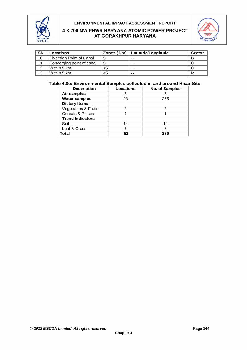
ENVIRONMENTAL IMPACT ASSESSMENT REPORT
4 X 700 MW PHWR HARYANA ATOMIC POWER PROJECT AT GORAKHPUR HARYANA
© 2012 MECON Limited. All rights reserved Page 144
Chapter 4
SN. Locations Zones ( km) Latitude/Longitude Sector 10 Diversion Point of Canal 5 -- B 11 Converging point of canal 5 -- O 12 Within 5 km <5 -- O 13 Within 5 km <5 -- M
Table 4.8e: Environmental Samples collected in and around Hisar Site
Description Locations No. of Samples Air samples 5 5 Water samples 28 265 Dietary Items Vegetables & Fruits 3 3 Cereals & Pulses 1 1 Trend Indicators Soil 14 14 Leaf & Grass 6 6
Grand Total 52 289

ENVIRONMENTAL IMPACT ASSESSMENT REPORT
4 X 700 MW PHWR HARYANA ATOMIC POWER PROJECT AT GORAKHPUR HARYANA
© 2012 MECON Limited. All rights reserved Page 145
Chapter 4
Fig. 4.5a : Base-map Showing Project Site and Radiological Survey Study Area – Divided in to Different Zones and Sectors.
N NNE
NE
ENEE
ESE
SE
SSESSSW
SW
WSW
WW
NW
NW
NNW

ENVIRONMENTAL IMPACT ASSESSMENT REPORT
4 X 700 MW PHWR HARYANA ATOMIC POWER PROJECT AT GORAKHPUR HARYANA
© 2012 MECON Limited. All rights reserved Page 146
Chapter 4
N
Terrestrial Sampling Points
Fig. 4.5b : Radiological Survey Study Area Showing Terrestrial Sampling Locations

ENVIRONMENTAL IMPACT ASSESSMENT REPORT
4 X 700 MW PHWR HARYANA ATOMIC POWER PROJECT AT GORAKHPUR HARYANA
© 2012 MECON Limited. All rights reserved Page 147
Chapter 4
N
Aquatic Sampling Points
Fig. 4.5c : Radiological Survey Study Area Showing Aquatic Sampling Locations

ENVIRONMENTAL IMPACT ASSESSMENT REPORT
4 X 700 MW PHWR GORAKHPUR ATOMIC POWER PROJECT HARYANA
© 2012 MECON Limited. All rights reserved Page 148
Chapter 4
4.3.3.1 Ambient Radiation Levels
The radiological survey samples were collected as per the practice of Health Physics Division BARC. These stations are marked in Fig. 4.5b and 4.5c. Methodology External gamma dose rate due to natural sources (cosmic rays, U, Th and K-40 deposits in the earth) is established using appropriate monitoring techniques (e.g. thermo-luminescent dosimeter (TLD) and high sensitivity background gamma chambers. Radioactivity levels in the environment are very low and call for special techniques. These have been standardized over the years by BARC. Sampling and analysis is carried out as per the Standard procedures of Health Physics Division, BARC. Gamma radiation level was measured in and around the site using Gamma dose rate tracer, using the instruments calibrated at Health Physics Division, BARC. The dose rate (µGy) measurements were carried out using Thermo-luminescent Dosimeter (TLD). Results Gamma radiation level was measured in and around the site using Gamma dose rate tracer (Table 4.8h). The gamma radiation levels ranged between 0.07-0.22 µGy/h. The measured gamma radiation levels around the project site are normal and comparable with Kakrapar and Kaiga sites. The dose rate (µGy) measurements were carried out using TLD. The results during January-March, 2011 is given in Table 4.8i.
Table 4.8h: Gama radiation levels (µGy/h) in different villages during January to March 2011 SN. Village Sector/ Zone Latitude/Longitude Range µGy/h Mean µGy/h 1 Kumharia (10) K/L (1.6-5 km) N 29.40484°,E 075.61498° 0.087-0.17 0.12 2 Kajalheri (10) N (1.6-5.0 km) N 29.44599°,E 075.60875° 0.087-0.148 0.12 3 Gorakhpur(10) C (1.6-5.0 km) N 29.45767°,E 075.65127° 0.078-0.12 0.11 4 Siwani (10) E (1.6-5.0 km) Not measured 0.096-0.13 0.11 5 Kirmara (10) F( 5-10 km) N 29.38327°,E 075.69610° 0.11-0.17 0.14 6 Kuleri (10) H ( 5 -10 km) N 29.37080°,E 075.66758° 0.10-0.18 0.14 7 Agroha (10) I ( 5 – 10 km) N29˚21’51.5”E075˚30’22.4” 0.11-0.18 0.14 8 Badopal (10) M (5-10 km) N 29º16’40.6",E075º38’10.6" 0.087-0.17 0.13 9 Talwandi (10) H (15 – 30 km) Not measured 0.07-0.16 0.12 10 Juglan (10) G (15-30 km) Not measured 0.05-0.13 0.09 11 Bahbalpur (10) G (15-30 km) N 29.16534°,E 075.48155° 0.061-0.15 0.11 12 Badopal (8) G (15-30 km) N 29º16’40.6",E075º38’10.6" 0.061-0.15 0.12 13 Bugana (8) G (15-30 km) Not measured 0.087-0.11 0.10 14 Sulakhani (8) G (15-30 km) Not measured 0.078-0.14 0.10 15 Dhansu (10) G (15-30 km) Not measured 0.07-0.12 0.10 16 Hisar (10) H (15-30 km) N29˚10’18.77” E075˚44’07.7” 0.12-0.22 0.16

ENVIRONMENTAL IMPACT ASSESSMENT REPORT
4 X 700 MW PHWR GORAKHPUR ATOMIC POWER PROJECT HARYANA
© 2012 MECON Limited. All rights reserved Page 149
Chapter 4
Table 4.8i: Radiation Dose Rate Measurements using TLD January to March 2011 Dose
Received (µGy)
Dose Rate (µGy/90 days)
Dose Received
(µGy)
Dose Rate (µGy/90 days)
Location
Latitude/Longitude Days Exposed
Indoor Outdoor Control ---- 97 45714 424 -- --- Hisar N29˚10’18.77” E075˚44’07.7” 93 69246 670 31413 307 Chikanwas -- 93 47850 463 44226 428 Asrawan -- 93 49146 475 28518 275 Fransi -- 93 3152.0 305 22422 216 Badopal N 29º16’40.6",E075º38’10.6" 93 47728 461 36416 353 Kajalheri N 29.44599°,E 075.60875° 93 45357 438 39532 383 Kumharia N 29.40484°,E 075.61498° 93 51626 500 3298.0 318 Bhoda Hosank N 29.35190º ,E 075.60155º 93 42725 414 29715 287 Kuleri N 29.37080°,E 075.66758° 92 55722 545 52324 512 Sabarwas N 29.40187°,E 075.62905° 92 4092.0 400 36140 353 Gorakhpur N 29.45767°,E 075.65127° 92 45535 446 3016.0 295 Nehla -- 92 52435 513 43928 429 Kirmara N 29.38327°,E 075.69610° 92 45634 446 3171.0 310 Nangthala N 29.21413°,E 075.53508° 92 4466.0 436 27425 268 Landheri N 29.18228°,E 075.39455° 92 4077.0 398 32620 319 Fatehabad N29º31’13.8",E075º26’16.8" 91 56614 560 42712 422 Ratla -- 91 42620 421 45964 454 Bhutan Kalan -- 91 53824 532 30216 299 Chandrawal -- 91 43741 432 28729 284 Jandli Kalan -- 91 45321 448 2497.0 247 Mochiwali -- 91 4182.0 414 2674.0 264 Barawal N 29.21444°,E 075.53527° 92 6094.0 596 53251 520 Adampur N 29º16’53.2",E075º28’30.9" 90 51018 510 2746.0 271 Bhattu Kalan -- 90 43560 535 51929 513 Dhand -- 90 43055 340 39275 387 Bahana N 29º21’55.1",E075º30’21.0" 90 51741 517 30226 299 Khajuri -- 90 39747 397 33413 330 Agroha N29˚21’51.5”E075˚30’22.4” 90 43152 431 36645 362 Thaska -- 89 43324 438 35521 359 Kanoh -- 89 49145 496 34572 349
4.3.3.2 Estimation of Pre-operational Base Line Levels of Natural and Fallout Radio-nuclides in Environmental Samples For base line survey, to estimate the levels of various radio-nuclides of natural (238U, 232Th, 40K) and fallout (137Cs and 90Sr) origin, different types of environmental samples were collected from the terrestrial and aquatic environs of the site up to a radial distance of 30km. The details of terrestrial and aquatic sampling locations are given in Table 4.8d and 4.8e, respectively. Figure 4.5b and 4.5c show the terrestrial and aquatic sampling locations respectively. Canal water, soil, cereals, pulses and vegetation samples were

ENVIRONMENTAL IMPACT ASSESSMENT REPORT
4 X 700 MW PHWR GORAKHPUR ATOMIC POWER PROJECT HARYANA
© 2012 MECON Limited. All rights reserved Page 150
Chapter 4
collected around the site. Table 4.8f gives the number and types of samples collected from various locations. Methodology The collected soil and biological samples were processed at site and were sent to Health Physics Division, BARC for gamma spectrometry and radiochemical analysis. Gross alpha and gross beta measurements were carried out at site. Soil samples were dried and sieved and the fraction containing less than 180 µm size were packed in a standard geometry for gamma spectrometry and stored for one month to attain secular equilibrium1, before analysis. Biological samples were oven dried, powdered and packed in standard geometry(1). Biological samples were ashed as per the standard procedure1 for the estimation 90Sr. The gamma spectrometric analysis1 of processed soil and biological samples and the analysis of levels of 238U, 232Th, 40K and 228Ra, were carried out at Health Physics Division, BARC, Mumbai. The samples were counted by gamma spectrometry with HPGe detector for the estimation of 238U, 232Th, 226Ra and 40K. 137Cs was estimated gamma spectro-metrically using HPGe detector (50% RE) system.
90Sr concentrations in soil and vegetation samples were estimated using radiochemical separation followed by beta counting as per the prescribed standard procedure given in Analytical Procedure Manual, 1992(1). Analysis for gross alpha and gross beta levels in air and water samples were carried out by radiochemical separation and gross beta counting / gross alpha counting. Results The results of radioactivity levels in air, water, soil and vegetation is given in Table 4.8j, k, l, m and n. Air samples A total of five (5) air samples were collected from the study area of the proposed project site and were analysed for gross alpha and beta activities. Table 4.8j presents the gross activities (alpha, beta) in air samples. The gross beta activity ranged between BDL (<0.007 Bq.m-3) to 0.017 Bq.m-3 and gross alpha ranged from 0.0002 to 0.003 Bq.m-3.
Table 4.8j: Levels of Gross Alpha and Gross Beta in Air Samples SN. Location Latitude/longitude Gross Beta
Activity(Bq/m3) Gross Alpha Activity, (Bq/m3)
1 Badopal N29˚24’58.3” E075˚33’00.4” BDL 0.0003 ±0.00009 2 Bhana N29˚22’11.8” E075˚29’59.0” BDL 0.0030 ±0.0004
1 Analytical Procedure Manual, Health Physics Division, BARC/HPD/1992/002, Bhabha Atomic Research Centre, Mumbai, India, 1992.

ENVIRONMENTAL IMPACT ASSESSMENT REPORT
4 X 700 MW PHWR GORAKHPUR ATOMIC POWER PROJECT HARYANA
© 2012 MECON Limited. All rights reserved Page 151
Chapter 4
SN. Location Latitude/longitude Gross Beta Activity(Bq/m3)
Gross Alpha Activity, (Bq/m3)
3 Sarangpur N29˚20’54.1” E075˚31’46.6” 0.017±0.005 0.0002 ±0.00009 4 Hisar N29˚10’18.77” E075˚44’07.7” BDL 0.0006 ±0.0001 5 Agroha N29˚21’51.5” E075˚30’22.4” 0.011±0.005 0.0005 ±0.0001
Minimum Detection Limit (MDL) for Gross Beta = = 0.01 Bq/m3 MDL for Gross Alpha =0.0002 Bq/m3
Radioactivity levels in water samples A total of fifteen (15) water samples were collected from the study area of the proposed project site and were analysed for gross alpha and beta activities. The activity levels are reported in Table 4.8k. Gross alpha activity in water ranged from 6.7 mBq.l-1 to 281.3 mBq.l-1. The gross beta activity ranged from MDL (<225 mBq.l-1) to 332.6 mBq.l-1. The gross alpha activities observed in water samples are higher than those observed in other power station sites. This can be attributed to the comparatively higher concentrations of Uranium in ground water.
Table 4.8k: Levels of Gross Alpha and Gross Beta in Water Samples Gross Alpha
mBq.l-1 Gross Beta
mBq.l-1 SN. Location Distance
(km) Sector Latitude / Longitude
Range Range 1 Kajalheri (8) 1.0-5.0 N N 29.44599°,E 075.60875° 23.4-48.8 BDL 2 Kumharia(25) 1.0 K-L N 29.40484°,E 075.61498° 10.3-133.0 BDL -288.98 3 Sabarwas(5) 1.0 I N 29.40187°,E 075.62905° 21.6-37.0 BDL 4 Gorakhpur(13) 1.0-5.0 C N 29.45767°,E 075.65127° 7.3 -58.8 BDL-271.4 5 Between 1 & 2(6) 5-10 N-L N 29.41760º,E 075.59850º 16.8-190 -- 6 Siswal (4) 15-30 J 6.7 -29.8 BDL-306 7 Bhoda Hushnak (8) 10-15 T N 29.35190º ,E 075.60155º 10.1-94.8 BDL 8 Adampur(5) 15-30 K -- 9.9 -96.8 BDL 9 Bhuna(2) 10-15 B -- 11.2-11.9 BDL
10 Sarangpur(5) 10-15 K N29˚20’54.1” E075˚31’46.6” 11.4 -40.0 BDL 11 Jagan(3) -- 10.0 -281.3 BDL 12 Badopal(6) 5-10 M -- 7.4 -48.2 BDL-278.8 13 Muhamadpur(4) N 29°27284,E 075°33454 24.9 32.2 BDL 14 Dhani Majra(5) 10-15 O N 29°29105,E 075°32434 21.4 -117.7 BDL-332.6 15 Fatehabad(10) 15-30 N -- 14.7-163.5 BDL Prescribed Limit for packaged drinking water by BIS (Ref) 100 1000 Detection Limit for Gross Alpha in water -5.6 mBq.l-1 Detection Limit for Gross Beta in water - 225 mBq.l-1
Radioactivity levels in soil A total of 14 soil samples were collected from the study area of the proposed project site for assessing the baseline radio-activity level in soil. Table 4.8l presents the concentrations of 226Ra, 238U and 40K in soil samples. The 226Ra activity in soil samples ranged from 9.6 to 70.9 Bq.kg-1dry wt. 238U activity varied from 11.5 to 70.8 Bq.kg-1dry dry wt. It can be seen that the activities 232Th activity varied from 20.2 to 118.7 Bq.kg-1dry dry wt. The observed concentrations of 226Ra and 238U in soil collected from the present study area are found to be higher than those observed in other power station sites of India. 40K concentrations in soil varied from 249.6 to 1353 Bq.kg-1dry wt. The observed values are comparable with those observed in other power station sites.

ENVIRONMENTAL IMPACT ASSESSMENT REPORT
4 X 700 MW PHWR GORAKHPUR ATOMIC POWER PROJECT HARYANA
© 2012 MECON Limited. All rights reserved Page 152
Chapter 4
Table 4.8m shows the 137Cs and 90Sr concentrations in soil samples from the study area of the proposed project. The levels of 137Cs and 90Sr are comparable to the levels reported elsewhere(2).
Table 4.8l : Natural Radioactivity Content in Soil Samples 226Ra 238U 232Th 40K Location
Distance (km)
Sector (Bq.kg-1dry)
Agroha 5-10 I 21.41.1 26.61.5 41.7 1.5 486.4 3.7 Gorakhpur 1.6-5 C 17.70.8 18.41.1 32.61.1 339.82.6 Kirmara 5-10 F 9.60.6 11.50.9 20.20.9 249.62.3 Kumharia 1.6 L 13.80.7 15.81.0 30.71.0 273.62.2 Kuleri 5-10 H 42.41.5 45.12.0 83.82.1 543.94.1 Kirmara 5-10 F 12.50.7 14.90.9 26.10.9 304.82.3 Kuleri 5-10 H 56.32.8 49.33.6 97.53.6 955.98.3 Agroha 5 -10 I 59.94.1 61.55.0 103.75.1 109112 Siswal -1 15-30 J 50.52.7 50.03.8 89.33.4 771.87.5 Siswal -2 15-30 J 53.92.6 49.53.3 83.03.2 798.27.4 Badon 15-30 G 70.92.4 70.816.2 118.713.8 1353 35 Kirmara 5-10 F 51.82.7 53.73.5 91.73.6 832.58.0 Kuleri 5 -10 H 56.32.9 49.33.6 97.53.6 955.98.3 Bhana 5-10 L 28.71.6 27.12.4 90.72.4 586.812.4
Table 4.8m: Concentrations of 137Cs and 90Sr in Soil samples
Location Distance (km) Sector 137Cs (Bq.kg-1dry) 90Sr (Bq.kg-1dry) Kumharia 1.6 L 0.60.07 <1.3 Gorakhpur 1.6-5 C 0.80.08 <1.3 Agroha 5-10 I <1.0 <1.3 Kirmara 5-10 F <1.0 NA Kirmara 5-10 F <1.0 <1.3 Kuleri 5 -10 H <1.0 NA Bhuna (radish) 5-10 L 2.40.16 NA Kuleri 5-10 H <1.0 <1.3 Kirmara 5-10 F <1.0 <1.3 Kuleri 5-10 H <1.0 NA Agroha 5 -10 I 2.50.4 NA Siswal (guave) 15-30 J 2.50.4 NA Siswal (amla) 15-30 J 4.90.3 NA Badon (guave) 15-30 G 3.10.2 NA
Activity levels at other locations of the country Kaiga(3) BDL to 65.4 Punjab(4) 1.28-6.25
2 UNSCEAR 2000, Sources and effects of ionizing radiation, Report to General Assembly, with Scientific Annexes, United Nation, 2000. 3 Karunakara N, Somashekarappa HM, Narayana Y, Avadhani DN, Mahesh HM, Siddappa K 137Cs concentration in the environment of Kaiga of south west coast of India, Health Physics 2001 Aug; 81(2):148-55.

ENVIRONMENTAL IMPACT ASSESSMENT REPORT
4 X 700 MW PHWR GORAKHPUR ATOMIC POWER PROJECT HARYANA
© 2012 MECON Limited. All rights reserved Page 153
Chapter 4
Radioactivity levels (137Cs, 90Sr and 40K) in biological samples Radioactivity levels in a number of food and related matrices are being monitored regularly. Two radio-nuclides that are considered important in this context are 137Cs and 90Sr. A total of ten (10) biota (biological) samples were collected from the study area of the proposed project site. Table 4.8n presents the results of analysis of biological samples, covering samples of grass, cereals, leaves, fruits, etc collected from the study area. The activity levels of 137Cs and 90Sr are comparable to the levels reported elsewhere(5).
Table 4.8n: Levels of 137Cs, 90Sr and 40K in Biological Samples
SN Location
Distance km
Sector Biota Samples
Cs-137 (Bq.kg-1 dry)
Sr-90 (Bq.kg-1 dry)
K-40 (Bq.kg-1 dry)
1 Kumharia 1.6 L Grass <0.17 <1.0 3.380.027 2 Kajalheri 1.6-5.0 N Bajra grain <0.17 <1.0 0.160.003 3 Kuleri 5-10 H Grass <0.17 <1.0 2.620.02 4 Agroha 5-10 I Grass <0.17 <1.0 1.380.01 5 Kirmara 5-10 F Grass <0.17 <1.0 2.270.02 6 Bhana 5-10 L Radish leaves <0.17 NA 1.9 0.01 7 Siswal 15-30 J Amla fruit <0.17 NA 0.460.008 8 Siswal 15-30 J Guava fruit <0.17 NA 0.470.007 9 Badon 15-30 G Guava leaves <0.17 NA 0.420.007 10 Badon 15-30 G Guava fruit <0.17 NA 0.760.01 4.4 TRAFFIC DENSITY
In order to assess the impact of future traffic load (due to the proposed plant) on the existing traffic infrastructure of proposed project site, the existing / baseline traffic density on NH 10 and at road inlet locations of proposed site was studied. The existing traffic density for different types of vehicles was counted at two locations during the study on a particular day for 24 hours. The monitoring locations are as follows: On National Highway No. 10 (at Badapol) – Hisar to Fatehabad On road leading to proposed project site joining NH 10 at Badapol. Tables 4.9a1 and 4.9a2 indicate the traffic density on NH 10 during weekends and weekdays, respectively. There is not much difference in the traffic density between weekends and week days. On weekends the traffic in all three categories is slightly more than that on the weekdays. There to be conservative, all further analysis has been done on the basis of traffic density on weekends. On weekends, the traffic density is highest for light motor vehicles (5147/d), followed by heavy motor vehicles (1841/d), two wheelers (1930/d) and there were no three wheelers. Total traffic density at this location is 14208.5 PCU per day.
4 Ajaykumar et al. Distribution, enrichment and principal component analysis for possible sources of naturally occurring and anthropogenic radionuclides in the agricultural soil of Punjab state, India. Radiation Protection Dosimetry, 2011, pp. 1-11. 5 UNSCEAR 2000, Sources and effects of ionizing radiation, Report to General Assembly, with Scientific Annexes, United Nation, 2000.

ENVIRONMENTAL IMPACT ASSESSMENT REPORT
4 X 700 MW PHWR GORAKHPUR ATOMIC POWER PROJECT HARYANA
© 2012 MECON Limited. All rights reserved Page 154
Chapter 4
Table 4.9a1: Traffic Density on NH 10 Hisar – Fatehabad on Weekends Traffic Volume (Vehicles Per Hour) w.r.t Hisar Time (Hrs.)
11.06. 2011 (Saturday)
Heavy Motor Vehicles (HMV)
Light Motor Vehicles (LMV)
Two Wheelers
Total Total Vehicles (PCU)
24.00 - 00.59 66 82 3 151 322.5 01.00 - 01.59 90 72 5 167 380.5 02.00 - 02.59 56 67 3 126 270 03.00 - 03.59 171 126 1 298 702.5 04.00 - 04.59 86 109 4 199 423.5 05.00 - 05.59 48 109 13 170 314 06.00 - 06.59 47 80 57 184 289.5 07.00 - 07.59 79 187 150 416 592.5 08.00 - 08.59 72 230 131 433 626.5 09.00 - 09.59 80 340 169 589 834.5 10.00 - 10.59 72 312 153 537 760.5 11.00 - 11.59 72 302 119 493 728.5 12.00 - 12.59 68 309 120 497 727.5 13.00 - 13.59 102 272 101 475 764.5 14.00 - 14.59 101 307 85 493 806 15.00 - 15.59 92 299 104 495 776.5 16.00 - 16.59 82 356 115 553 837.5 17.00 - 17.59 76 371 160 607 864.5 18.00 - 18.59 84 378 166 628 902 19.00 - 19.59 95 312 157 564 831.5 20.00 - 20.59 47 204 65 316 479.5 21.00 - 21.59 61 128 27 216 388.5 22.00 - 22.59 48 102 19 169 306.5 23.00 - 23.59 46 93 3 142 279 Total Per Day 1841 5147 1930 8918 14208.5 Passenger Car Unit (PCU) : 3 for HMV, 1.5 for LMV; 0.5 for Two Wheelers
Table 4.9a2: Traffic Density on NH 10 Hisar – Fatehabad on Weekdays
Traffic Volume (Vehicles Per Hour) w.r.t Hisar Time (Hrs.) 15.06. 2011 (Wednesday)
Heavy Motor Vehicles (HMV)
Light Motor Vehicles (LMV)
Three Wheelers
Two Wheelers
Total Vehicles (PCU)
24.00 - 00.59 65 77 2 144 311.5 01.00 - 01.59 85 68 2 155 358 02.00 - 02.59 52 63 1 116 251 03.00 - 03.59 102 117 0 219 481.5 04.00 - 04.59 80 105 2 187 398.5 05.00 - 05.59 52 102 8 162 313 06.00 - 06.59 41 76 55 172 264.5 07.00 - 07.59 85 180 150 415 600 08.00 - 08.59 68 219 135 422 600 09.00 - 09.59 84 323 155 562 814 10.00 - 10.59 76 296 145 517 744.5 11.00 - 11.59 68 285 135 488 699 12.00 - 12.59 73 303 126 502 736.5 13.00 - 13.59 98 258 95 451 728.5

ENVIRONMENTAL IMPACT ASSESSMENT REPORT
4 X 700 MW PHWR GORAKHPUR ATOMIC POWER PROJECT HARYANA
© 2012 MECON Limited. All rights reserved Page 155
Chapter 4
Traffic Volume (Vehicles Per Hour) w.r.t Hisar Time (Hrs.) 15.06. 2011 (Wednesday)
Heavy Motor Vehicles (HMV)
Light Motor Vehicles (LMV)
Three Wheelers
Two Wheelers
Total Vehicles (PCU)
14.00 - 14.59 105 292 91 488 798.5 15.00 - 15.59 88 284 101 473 740.5 16.00 - 16.59 86 332 117 535 814.5 17.00 - 17.59 70 342 149 561 797.5 18.00 - 18.59 80 369 157 606 872 19.00 - 19.59 105 296 172 573 845 20.00 - 20.59 53 194 60 307 480 21.00 - 21.59 55 122 25 202 360.5 22.00 - 22.59 60 97 22 179 336.5 23.00 - 23.59 52 88 4 144 290 Total Per Day 1783 4888 1909 8580 13635.5 Passenger Car Unit (PCU) : 3 for HMV, 1.5 for LMV; 0.5 for Two Wheelers
Tables 4.9b1 and 4.9b2 indicate the traffic density on road leading to project site from NH 10 on weekend and weekdays, respectively. There is not much difference in the traffic density between weekends and week days. On weekends the traffic in all three categories is slightly more than that on the weekdays. There to be conservative, all further analysis has been done on the basis of traffic density on weekends. On weekends, the traffic density is highest for two wheelers (452/d), followed by light motor vehicles (341/d) and heavy vehicles (11/d). Total traffic density at this location is 766 per day. This road is mostly used for the village transport from NH10.
Table 4.9b1: Traffic Density on Road leading to project site from NH 10 on Weekends
Traffic Volume (Vehicles Per Hour) w.r.t Hisar Time (Hrs.) 11.06. 2011 (Saturday)
Heavy Motor Vehicles (HMV)
Light Motor Vehicles (LMV)
Three Wheelers
Two Wheelers
Total Vehicles (PCU)
24.00 - 00.59 0 4 0 4 6 01.00 - 01.59 0 3 0 3 4.5 02.00 - 02.59 0 1 1 2 2 03.00 - 03.59 0 0 0 0 0 04.00 - 04.59 0 1 3 4 3 05.00 - 05.59 2 5 4 9 15.5 06.00 - 06.59 0 3 18 21 13.5 07.00 - 07.59 1 5 14 19 17.5 08.00 - 08.59 1 21 37 58 53 09.00 - 09.59 2 26 37 63 63.5 10.00 - 10.59 1 41 35 76 82 11.00 - 11.59 0 26 21 47 49.5 12.00 - 12.59 0 22 36 58 51 13.00 - 13.59 0 15 28 43 36.5 14.00 - 14.59 0 8 21 29 22.5 15.00 - 15.59 2 18 22 40 44 16.00 - 16.59 0 18 21 39 37.5 17.00 - 17.59 1 14 20 34 34 18.00 - 18.59 0 11 36 47 34.5
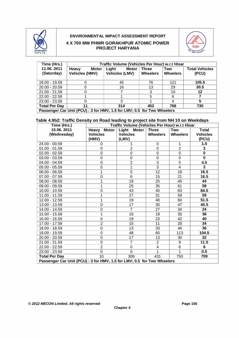
ENVIRONMENTAL IMPACT ASSESSMENT REPORT
4 X 700 MW PHWR GORAKHPUR ATOMIC POWER PROJECT HARYANA
© 2012 MECON Limited. All rights reserved Page 156
Chapter 4
Traffic Volume (Vehicles Per Hour) w.r.t Hisar Time (Hrs.) 11.06. 2011 (Saturday)
Heavy Motor Vehicles (HMV)
Light Motor Vehicles (LMV)
Three Wheelers
Two Wheelers
Total Vehicles (PCU)
19.00 - 19.59 0 45 76 121 105.5 20.00 - 20.59 0 16 13 29 30.5 21.00 - 21.59 0 7 3 10 12 22.00 - 22.59 1 1 5 6 7 23.00 - 23.59 0 3 1 4 5 Total Per Day 11 314 452 766 730 Passenger Car Unit (PCU) : 3 for HMV, 1.5 for LMV; 0.5 for Two Wheelers
Table 4.9b2: Traffic Density on Road leading to project site from NH 10 on Weekdays
Traffic Volume (Vehicles Per Hour) w.r.t Hisar Time (Hrs.) 15.06. 2011
(Wednesday)
Heavy Motor Vehicles (HMV)
Light Motor Vehicles (LMV)
Three Wheelers
Two Wheelers
Total Vehicles
(PCU) 24.00 - 00.59 0 1 0 1 1.5 01.00 - 01.59 0 2 0 2 3 02.00 - 02.59 0 0 0 0 0 03.00 - 03.59 0 0 0 0 0 04.00 - 04.59 0 2 3 5 4.5 05.00 - 05.59 0 1 3 4 3 06.00 - 06.59 1 5 12 18 16.5 07.00 - 07.59 0 6 15 21 16.5 08.00 - 08.59 1 19 25 45 44 09.00 - 09.59 1 25 35 61 58 10.00 - 10.59 0 43 40 83 84.5 11.00 - 11.59 1 27 31 59 59 12.00 - 12.59 1 19 40 60 51.5 13.00 - 13.59 0 17 30 47 40.5 14.00 - 14.59 0 7 27 34 24 15.00 - 15.59 1 16 18 35 36 16.00 - 16.59 0 19 23 42 40 17.00 - 17.59 2 15 11 28 34 18.00 - 18.59 0 13 33 46 36 19.00 - 19.59 0 48 65 113 104.5 20.00 - 20.59 0 17 13 30 32 21.00 - 21.59 0 7 2 9 11.5 22.00 - 22.59 2 0 4 6 8 23.00 - 23.59 0 0 1 1 0.5 Total Per Day 10 309 431 750 709 Passenger Car Unit (PCU) : 3 for HMV, 1.5 for LMV; 0.5 for Two Wheelers

ENVIRONMENTAL IMPACT ASSESSMENT REPORT
4 X 700 MW PHWR GORAKHPUR ATOMIC POWER PROJECT HARYANA
© 2012 MECON Limited. All rights reserved Page 157
Chapter 4
4.5 GEOLOGY AND HYDROGEOLOGY 4.5.1 Introduction
The study area is located at the intersection of Northern Latitude 290 26’ 30” N and east Longitude 750 37’ 56” E and can be located in the Survey of India Topo-sheet No. H43P10 and H43P11. The area falls under the seismic Zone-III in the Seismic Zoning Map of India (IS:1893, 2002) The maximum Modified Mercalli (MM) intensity of seismic shaking expected in the zone is VII, termed here as Moderate Damage Risk Zone. The climate of the region can be classified into semi-arid and hot which is mainly dry with very hot summer and cold winter except during monsoon season when moist air of oceanic origin penetrates into the region. The hot weather season starts from mid March to last week of the June followed by the south- west monsoon which lasts till September. The transition period from September to November forms the post-monsoon season. The winter season starts in December and remains up to February. Rainfall during as observed by IMD (Source: IMD website) during last five years from 2006 to 2011 in the districts falling in the study area is given in Table 4.10a. The normal annual rainfall of Fatehabad district is 373 mm which falls over the area in 22 rainy days. The south west monsoon sets in from last week of June and withdraws in end of September, contributes about 80% of annual rainfall. July and August are the wettest months. Rest 20% rainfall is received during non-monsoon period in the wake of western disturbances and thunder storms. Generally rainfall in the district increases from southwest to northeast. Normal Annual Rainfall : 373 mm Normal monsoon Rainfall : 297 mm Mean Maximum Temperature : 41.6C(May June) Mean Minimum Temperature : 5.5 C(January) Normal Rainy days : 22 Annual Mean Wind Speed : 1.25m/s Maximum Wind Speed : 1.95m/s
Table 4.10a: Rainfall (IMD data) During 2006-2011 in Districts Falling in the Study Area
Rainfall in mm Year Jan Feb Mar April May June July Aug Sept Oct Nov Dec Total
District : Fatehabad 2006 0 0 48.3 0 45.8 54.5 75.3 21.7 77.3 0 0 0 322.9 2007 - - - - - 76.6 50.3 26 27.7 0 0.8 4 185.4 2008 0 1.5 0.1 15.5 25 168.8 32.7 169.7 58.3 0.5 2.7 0 474.8 2009 4.3 5 2.3 0 0 3.9 60.2 11.3 55.3 0 142.3 2010 0 14 0 0 0 0 133 68.7 106.7 0 0 8 330.4
Average 1.07 5.12 12.7 3.88 17.7 60.76 70.3 59.48 65.06 0.1 0.88 3 291.16 District : Hisar
2006 0.4 0 20.1 1.2 45.7 32.6 74.8 11.4 53.4 0 0 7.3 246.9 2007 0 89.5 52.7 5.4 52.1 124 45.6 82.1 39.4 0 0.7 4.3 495.8

ENVIRONMENTAL IMPACT ASSESSMENT REPORT
4 X 700 MW PHWR GORAKHPUR ATOMIC POWER PROJECT HARYANA
© 2012 MECON Limited. All rights reserved Page 158
Chapter 4
Rainfall in mm Year Jan Feb Mar April May June July Aug Sept Oct Nov Dec Total 2008 3.5 2.4 0 11.9 50.4 103.7 83.7 115.6 63.1 3.3 8.3 0.8 446.7 2009 7.8 8 3.8 12.8 20.1 20.4 51.3 11.5 125.3 0 0 0.2 261.2 2010 8 3 2.4 0.4 0.6 35.9 147.4 86.6 81.8 0 0 14.2 380.3
Average 3.94 20.6 15.8 6.34 33.8 63.32 80.56 61.44 72.6 0.66 1.8 5.36 366.18 4.5.2 Physiography
The study area is located in the Indo-gangetic alluvial Plains. The area is an alluvial plain of indo-gangetic basin. No perennial river flows through the district, however a seasonal river i.e Ghaggar is flowing through Ratia and Jakhal. Bhakra and western Yamuna are two main canals that irrigate most of the part of area. The area is by and large flat and plain flat terrain is interrupted by the randomly located sand dunes along the Ghaggar River, which are outside the study area. The regional gradient of the area is from north to south west with an average gradient of 0.27m/km. The area surrounding the proposed site is flat terrain with average elevation of about 211m. The physio-graphy of the study area is shown in Drg. No. MEC/11/S2/Q6SY/02. The soil of the region is sandy loam to loamy sands .
4.5.3 Drainage About 80% of the study area falls in Fatehabad district and the rest in Hisar district. The two districts are alluvial plain of Indo-Gangetic basin with almost flat terrain interrupted by randomly located sand dunes along the Ghaggar River. There is only a seasonal river (Ghaggar), and no perennial river, flowing through the two districts. Bhakra and Western Yamuna are two main canals which irrigate most part of these districts. The study area being a flat terrain is conspicuous by absence of any well defined natural drainage system. As per Haryana Space Application Centre (HARSAC, Hisar), there are no natural drainage channels passing through project and township areas. At the project site, general slope is away from canal to south direction. The drainage is of inland type and the excess rainwater, accumulates in natural /artificial depressions. However, out of study area in the northern part of the district, the Ghaggar River drains the area. The river course falling in the area is very narrow and often causes floods when heavy rainfall occurs in the catchment area.
4.5.4 Geological Features
The site area lies on the western part of Indo-gangetic alluvial plain on the Punjab side, adjoining the Rajasthan shelf, separated underneath the alluvium, by the NW-SE trending Lahore-Saharsa Ridge. The geological formations met within the region are Indo-Gangetic alluvium consisting of Newer and older alluvium with a thin blanket of aeolian deposits. The age of these formations range from upper-Pleistocene to Recent. Though the formations were laid down from upper-Pleistocene to Recent age, they are conformable with each other. Exploratory drilling in the area indicates that these Quaternary unconsolidated

ENVIRONMENTAL IMPACT ASSESSMENT REPORT
4 X 700 MW PHWR GORAKHPUR ATOMIC POWER PROJECT HARYANA
© 2012 MECON Limited. All rights reserved Page 159
Chapter 4
sediments are underlain by hard rock formations of Achaean age comprising of Granites, schists and gneisses. Bed rock is shallow in south western part of the district and thickness of alluvium increases gradually towards northeast. The maximum thickness of alluvium so far recorded in the boreholes drilled in Fatehabad district is 365.7m at Jhalnia (29031’00” and 75034’30”), about 10km north of the project site. The project site is located on alluvial soil made up of both older and newer alluvium with a thickness estimated to be of the order of about 300m, below which hard rock formation of the Lahore-Sahara Ridge is reported to occur. Data from bore holes (up to 60 m depth) at the project site indicates that the substrata consist of alternate layers of sandy silt/silty sand and silty clay/sandy clay (each layer being of approx. 4m thickness) up to the entire depth of the bore holes. The strata at the depth of the RB foundation level (17m) is silty clay in nature. N value at 17m depth is 40 and the N value increases progressively to 609 at 58 m depth. While the sub-surface conditions at this site are different from that at Narora, it may be possible to adopt at this site, foundation of the type adopted at NAPP, with modifications as required by detailed studies, in view of the reduced seismicity at the site.
4.5.5 Hydrogeology
As per bore hole data at site, the water table is 3 m below ground level in the month of July (Source: site selection committee report). It is likely that the water table may rise to a higher level during rainy seasons. Ground water movement is reported to be both West and W-SW, nearly parallel to the canal flow. Hydraulic gradient is reported to be around 50-70 cms/km which is quite low, indicating poor transitivity of the sub-surface. This would be due to the predominance of clay layers in the substrata. The ground water table as monitored in the study area during summer season is given in Table 4.10b. Table 4.10b: Ground Water Table of Well Investigated in the Study Area
Stn. No.
Name of Village
Distance (km) / Direction w.r.t. Project Site
Water Table w.r.t Ground Level (m)
Reduced level (m)
Water Table w.r.t M.S.L (m)
H 1 Samani 5.5, SE 4.3 211 206.7 H 2 Kirmara 9.0, SE 12.7 211 198.3 H 3 Kirmara 9.0, SE 9.6 211 201.4 H 4 Kanoh 14.5, ESE 10.8 211 200.2 H 5 Nehla 9.5, E 7.6 211 203.4 H 6 Nehla 9.5. E 6.5 211 204.5 H 7 Dahman 9.0, E 3.8 211 207.2 H 8 Baijalpur 8.5, NE 7.6 211 203.4 H 9 Jandli kalan 6.0 N 7.3 211 203.7 H 10 Jandli Khurd 7.5 NNE 7.4 211 203.6 H 11 Jandli kalan 6.0 N 5.5 211 205.5 H 12 Badopal 8.0 WSW 4.6 211 206.4 H 13 Kumahria 4.25, SSW 3.2 211 207.8 H14 Gorakhpur 3.5, E 3.0 211 208.0 H15 Chaubara 5.5, NE 3.4 211 207.6 H16 Mochiwali 6.5 NE 3.7 211 207.3

ENVIRONMENTAL IMPACT ASSESSMENT REPORT
4 X 700 MW PHWR GORAKHPUR ATOMIC POWER PROJECT HARYANA
© 2012 MECON Limited. All rights reserved Page 160
Chapter 4
Stn. No.
Name of Village
Distance (km) / Direction w.r.t. Project Site
Water Table w.r.t Ground Level (m)
Reduced level (m)
Water Table w.r.t M.S.L (m)
H17 Chandrawal 9.5, NE 8.1 211 202.9 H18 Bhuthan kalan 12, NNW 21.3 211 189.7 H19 Dhangar 10.5, WNW 13.1 211 197.9
The depth of ground water level in the study area in Fatehabad District as observed by Central Ground Water Board (CGWB) during pre-monsoon and post monsoon season is given in Figures 4.6a and 4.6b. The observed water level (Table 4.10b) during summer season in the study area during the present study matches with the ground water table values of CGWB. In general it can be observed that the ground water table with the study area is between 3 to 20m.

ENVIRONMENTAL IMPACT ASSESSMENT REPORT
4 X 700 MW PHWR GORAKHPUR ATOMIC POWER PROJECT HARYANA
© 2012 MECON Limited. All rights reserved Page 161
Chapter 4
SI
Figure 4.6a: Depth of Ground Water Table Pre-Monsoon in the Study Area (CGWB, 2008)

ENVIRONMENTAL IMPACT ASSESSMENT REPORT
4 X 700 MW PHWR GORAKHPUR ATOMIC POWER PROJECT HARYANA
© 2012 MECON Limited. All rights reserved Page 162
Chapter 4
Figure 4.6b: Depth of Ground Water Table Post-Monsoon in the Study Area (CGWB, 2008)
4.5.6 Seismo-tectonics
ENVIRONMENTAL IMPACT ASSESSMENT REPORT
4 X 700 MW PHWR GORAKHPUR ATOMIC POWER PROJECT HARYANA
© 2012 MECON Limited. All rights reserved Page 163
Chapter 4
The site area lies in Seismic Zone III in the Seismic Zoning Map of India (IS:1893, 2002). The site is situated on the ridge between the Bouguer gravity anomaly contours of -30 and -40 m Gal, on a contour interval of -10m Gal. The highest value in the site area is greater than - 20 m Gal. The important tectonic features around this site within a radius of 300 km are as follows: The important tectonic features to the north of alluvial plains in the Himalayan region are, (a) Frontal Himalayan Thrust (FHT), (b) Main Boundary Thrust (MBT), and (c) Main Central Thrust (MCT) at distances of about 190, 215 and 295 km respectively to the north-east of the site. MBF and MCT run all along the 2400 km length of the Himalayas and are related to Himalayan orogeny. A NW-SE striking Sargoda-Lahore-Delhi ridge underlies the alluvium. In the Seismo-tectonic Atlas (GSI, 2000) the boundary of this ridge is demarcated for the portion north-west of Ferozpur but not to its south-east falling in Punjab-Haryana-Delhi Area. Some of the features in the region are detailed below: i. Some transverse faults or tear faults have been identified along the northern fringe of
Indo-gangetic plain. Important among them are the Ropar Fault about 180 km to the NNE and Ghaggar Fault about 170 km to the NE. Yamuna tear fault/Paonta fault is about 210 km, ENE of the site. These tear faults generally displaces the HFT, MBT and the Recent Alluvium and hence are reported to be younger and active during post-Pleistocene time.
ii. In the Seismo-tectonic Atlas (GSI, 2000) a lineament is shown to extend from Ropar
fault into the alluvial plain in NE-SW direction for about 260 km and it lies 80 km NW of the site. The lineament passes over the buried Sargoda-Lahore-Delhi Ridge.
iii. The most significant subsurface tectonic feature to the SE of the site is the NE-SW
treading Delhi-Hardwar Ridge bound by parallel faults on either side. The western fault and the eastern fault are at distances of about 95 km and 140 km from the site respectively. These are not shown on Seismotectonic Atlas (GSI, 2000). However, one subsurface fault trending NE-SW named as Mahendragarh-Dehradun fault running over 295 km is shown in the Atlas. It lies at a distance of 120 km from the site and is obliquely disposed between the above said parallel faults.
iv. To the east of the subsurface Hardwar Ridge, the Sohna-Delhi Fault is associated with
a hot spring at a distance of 190 km from the site. Further east at a distance of about 255 km lies the ENE-WSW to EW treading Moradabad Fault beneath the alluvium in the plains of Uttar Pradesh.
v. A minor lineament with MNE-SSW trend and 220 km length passes close to the site at
a distance of 25 km.
vi. As per the Seismo-tectonic Atlas (GSI, 2000) no significant tectonic feature is seen to the west of the site within 300 km radius except those in the southwestern side of which

ENVIRONMENTAL IMPACT ASSESSMENT REPORT
4 X 700 MW PHWR GORAKHPUR ATOMIC POWER PROJECT HARYANA
© 2012 MECON Limited. All rights reserved Page 164
Chapter 4
Sardar Shahar fault that strikes NNE-WSW with a length of 270 km at a distance of 120 km is note worthy. Raisingh Nagar lineament, Tonk lineament, etc. are farther away from site.
vii. No capable fault exists within 5 km .The site is engineer-able from this consideration.
4.6 LANDUSE PATTERN
Land-use pattern in the study area as shown in the satellite imagery (LISS III, March 2011) is shown in Drg. No. MEC/11/S2/Q6SY/03 and given in Table 4.11a. The study area as per the satellite imagery covers 17.76% built-up area, 75.11% agricultural land (including horticultural plantations), 6.28 scrubs (non-forest area) covered area and 0.84% water bodies.
Table 4.11a: Land Use Pattern of the Study Area SN. Type of Land-use Area in ha. Percent Landuse 1 Built-up Land (settlements) 5591.51 17.76 2 Agricultural Land Crop Land 9198.33 29.21 Plantations 14453.48 45.90 Total 75.11 3 Scrubs 1977.95 6.28 4 Water Bodies Canal 265 0.84 Tanks 0.97 0.00 Total 0.00 Grand Total 31487.24 100.00
In Haryana the classification of land have been done for assessment of land holding taxes, by relying on classification of soil as an indirect indicator of measure of land productivity. The land has been divided, under five classes I to V (based on broad soil classification(6)), in to Abi, Chahi, Nehri, Barani, Banjar, Kallar, Thur, Sem, etc. Nehri is irrigated land is placed under class I, while Banjar, Kallar, Thur and Sem come under Class V category. Neri is the land where the irrigation source is canal, while Chahi, Tal, Barani are land where canal is not the irrigation source. Tibba is undulated land with sand dunes and Gair-mumkin is non-cultivable land belonging to Government allotted to the panchayat for community activities. Based on the above land classification the village wise breakup of land under acquisition for project and township are given in Table 4.11b. The land use pattern of the project site is given in Table 4.11b. The power plant site is predominantly double crop agriculture land. About 89% of the land being used for the project and township is agricultural land and about 11% is waste land.
Table 4.11b: Land Use Pattern of the Project Site Type of Land Project Site (Ha) Township (Ha) Total Land-use
% 6 Dynamics of Agriculture Development, Vol. 3. : Policy Planning & Liberalisation. By K.S. Dhindsa & Anju Sharma. Concept Publication Company. 2001.
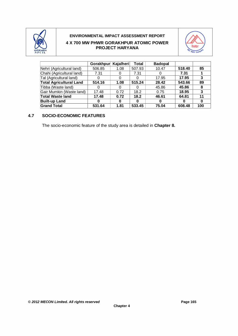
ENVIRONMENTAL IMPACT ASSESSMENT REPORT
4 X 700 MW PHWR GORAKHPUR ATOMIC POWER PROJECT HARYANA
© 2012 MECON Limited. All rights reserved Page 165
Chapter 4
Gorakhpur Kajalheri Total Badopal Nehri (Agricultural land) 506.85 1.08 507.93 10.47 518.40 85 Chahi (Agricultural land) 7.31 0 7.31 0 7.31 1 Tal (Agricultural land) 0 0 0 17.95 17.95 3 Total Agricultural Land 514.16 1.08 515.24 28.42 543.66 89 Tibba (Waste land) 0 0 0 45.86 45.86 8 Gair Mumkin (Waste land) 17.48 0.72 18.2 0.75 18.95 3 Total Waste land 17.48 0.72 18.2 46.61 64.81 11 Built-up Land 0 0 0 0 0 0 Grand Total 531.64 1.81 533.45 75.04 608.48 100
4.7 SOCIO-ECONOMIC FEATURES
The socio-economic feature of the study area is detailed in Chapter 8.
ENVIRONMENTAL IMPACT ASSESSMENT REPORT
4 X 700 MW PHWR HARYANA ATOMIC POWER PROJECT AT GORAKHPUR HARYANA
© 2012 MECON Limited. All rights reserved Page 166
Chapter 5
CHAPTER 5 : ANTICPATED ENVIRONMENTAL IMPACTS & MITIGATION MEASURES
5.0 ANTICPATED ENVIRONMENTAL IMPACTS & MITIGATION MEASURES 5.1 INTRODUCTION
In this chapter, the anticipated environmental impacts and the proposed mitigation measures for the proposed Haryana Atomic Power Project (HAPP) have been described.
Impact prediction is a way of mapping the environmental consequences of the significant aspects of the proposed plant. The impact assessment will broadly cover the following information and components: - Assessment of physical effects for all phases including location, design,
construction, operation and possible accidents. - Estimation by type and quantity of expected contaminants and emissions (air, water,
noise, solid wastes) resulting from the operation of the proposed plant.
The anticipated environmental impacts of the proposed plant are discussed below under the following categories:
Impacts and mitigation measures due to project siting (location). Impacts and mitigation measures due to project design. Impacts and mitigation measures during construction. Impacts and mitigation measures during operation. Impacts and mitigation measures because of possible accidents.
5.2 IMPACTS AND MITIGATION MEASURES DUE TO PROJECT SITING (LOCATION)
Impacts and Mitigation Measures The project site is located in Gorakhpur Village in Bhuna Block of Tehsil, Sub-division and District Fatehabad of Haryana State as shown in Fig. 2.1 (Chapter 2). The proposed project is planned in total 1503.6 acres or 608.5 ha of land for the atomic power plant (including exclusion zone) and the township (for plant personnel and CISF personnel). The village and land type wise breakup of land is given in Table 5.1. The main project area is mostly agricultural land interspersed with scattered trees and small patches of waste / barren land. Out of the total land required for the main plant area, about 515 ha is agricultural land and about 18.0 ha is not cultivable waste / barren land. There is no forest land involved in the power plant project site and also in the township site. For the proposed project the Project Affected Persons (PAPs) includes only land Oustees and no displacement of homestead population is involved. There are about 99 Dhanis (house constructed in agricultural land) which are used temporarily for facilitating agricultural activity. In the power plant site, about 1027 Eucalyptus trees and an

ENVIRONMENTAL IMPACT ASSESSMENT REPORT
4 X 700 MW PHWR HARYANA ATOMIC POWER PROJECT AT GORAKHPUR HARYANA
© 2012 MECON Limited. All rights reserved Page 167
Chapter 5
abandoned canal is present. In the plant site of the project area, which falls in the centre of the project site about 575 eucalyptus trees are standing. In Haryana the classification of land have been done for assessment of land holding taxes, by relying on classification of soil as an indirect indicator of measure of land productivity. The land has been divided, under five classes I to V (based on broad soil classification(1)), in to Abi, Chahi, Nehri, Barani, Banjar, Kallar, Thur, Sem, etc. Nehri is irrigated land is placed under class I, while Banjar, Kallar, Thur and Sem come under Class V category. Nehri is the land where the irrigation source is canal, while Chahi, Tal, Barani are land where canal is not the irrigation source. Tibba is undulated land with sand dunes and Gair-mumkin is non-cultivable land belonging to Government allotted to the panchayat for community activities. Based on the above land classification the village wise breakup of land under acquisition for project and township are given in Table 5.1a.
Table 5.1a: Total Land Requirement and Land-use at the Project Site Project Site Township
Gorakhpur Kajalheri Total Badopal Total Type of Land
Acres Ha Acres Ha Acres Ha Acres Ha Acres Ha
Land-use %
Nehri (Agricultural
land) 1252.43 506.85 2.68 1.08 1255.1 507.93 25.87 10.47 1280.98 518.40 85
Chahi (Agricultural
land) 18.06 7.31 0 0 18.06 7.31 0 0 18.06 7.31 1
Tal (Agricultural
land) 0 0 0 0 0 0 44.36 17.95 44.36 17.95 3
Total Agricultural
Land 1270.49 514.16 2.68 1.08 1273.2 515.24 70.23 28.42 1343.4 543.66 89
Tibba (Waste land) 0 0 0 0 0 0 113.33 45.86 113.33 45.86 8
Gair Mumkin (Waste land) 43.19 17.48 1.79 0.72 44.98 18.2 1.86 0.75 46.84 18.95 3
Total Waste land 43.19 17.48 1.79 0.72 44.98 18.2 115.19 46.61 160.17 64.81 11
Grand Total 1313.68 531.64 4.46 1.81 1318.2 533.45 185.42 75.04 1503.56 608.48 100
The existing approach road from NH10 to the project site is from Badopal village (on NH10). This road will be re-strengthened for movement of Heavy and Over Dimensional Consignment (ODC) vehicles. The existing village roads passing through the project area will be suitably diverted externally along the plant boundary. The impacts and mitigation measures of locating the plant at the land acquisition for the proposed site is given in Table 5.1b.
1 Dynamics of Agriculture Development, Vol. 3. : Policy Planning & Liberalisation. By K.S. Dhindsa & Anju Sharma. Concept Publication Company. 2001.

ENVIRONMENTAL IMPACT ASSESSMENT REPORT
4 X 700 MW PHWR HARYANA ATOMIC POWER PROJECT AT GORAKHPUR HARYANA
© 2012 MECON Limited. All rights reserved Page 168
Chapter 5
Table 5.1b: Impacts and Mitigation Measures of Locating HAPP at the Proposed Site SN.
Issues in Locating the Site
Area (ha) / Numbers
Impacts Mitigation Measures
1 Main Plant Area a. Agricultural Land 515.24 Only land Oustees and
no homestead population involved. For project site (Gorakhpur & Kajalheri village) total of 854 Project Affected People (PAPs) due to land acquisition.
Land to be acquired through Haryana Government taking in to account the R&R issues of Haryana R&R policy 2010 – for details of R & R Policy please see Annexure IB. Compensation will be paid as per Haryana R & R Policy 2010. The R & R Plan for the PAPs is given below.
b. Barren-land / wasteland
18.2 The land is non-cultivable waste land / barren land.
No mitigation measure required except for the R&R issues as above.
c. Dhanis in the Power Plant Project Area covering 1 ha land.
99 The 99 Dhanis will have to be cleared (house constructed in agricultural land) which are used temporarily for facilitating agricultural activity.
Compensation will be paid as per Haryana R & R Policy 2010. The displacement due to the project involves only land Oustees and no homestead population involved.
d. Eucalyptus Trees in the Power Plant Project Area
575 The 575 trees will have to be cut.
Additional trees will be planted as part of green belt development within the project area.
e. Abandoned Canal (2 ha) present in the Power Plant Project Area.
Canal covering 2 ha
This will be demolished. The canal is abandoned and thus no mitigation measure required.
f. Village roads passing through residential complex area.
- Will be blocked The existing village road roads passing through the project area will be suitably diverted externally along the residential complex boundary – so as to minimize the inconvenience to local inhabitants.
g. Existing road from Badopal Village on NH10 to Power Plant Project Site.
- While making the existing road as project site approach road may cause inconvenience to local inhabitants.
The approach road from NH10 to the project site (5 km) will be re-strengthened / extended to the project / township site for movement of Heavy and Over Dimensional (ODC) vehicles, and will be available for use by public. Alternate road connecting village Kajalheri to NH10 at Badopal already exists.
h. Drainage Pattern of the Area
- There is no drainage channel within the plant and township area and thus impact of changes in local drainage pattern
No major mitigation measures are required except that a garland drainage system will be provided all along the plant site boundary as well as residential complex
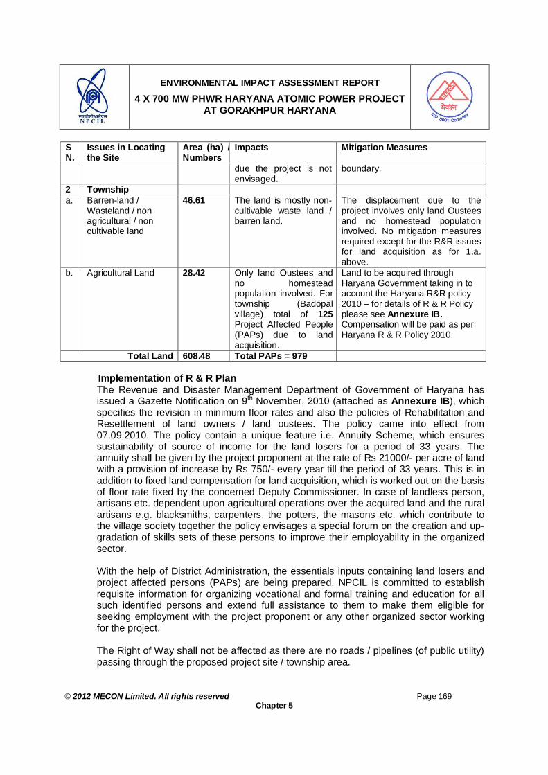
ENVIRONMENTAL IMPACT ASSESSMENT REPORT
4 X 700 MW PHWR HARYANA ATOMIC POWER PROJECT AT GORAKHPUR HARYANA
© 2012 MECON Limited. All rights reserved Page 169
Chapter 5
SN.
Issues in Locating the Site
Area (ha) / Numbers
Impacts Mitigation Measures
due the project is not envisaged.
boundary.
2 Township a. Barren-land /
Wasteland / non agricultural / non cultivable land
46.61 The land is mostly non-cultivable waste land / barren land.
The displacement due to the project involves only land Oustees and no homestead population involved. No mitigation measures required except for the R&R issues for land acquisition as for 1.a. above.
b. Agricultural Land 28.42 Only land Oustees and no homestead population involved. For township (Badopal village) total of 125 Project Affected People (PAPs) due to land acquisition.
Land to be acquired through Haryana Government taking in to account the Haryana R&R policy 2010 – for details of R & R Policy please see Annexure IB. Compensation will be paid as per Haryana R & R Policy 2010.
Total Land 608.48 Total PAPs = 979 Implementation of R & R Plan The Revenue and Disaster Management Department of Government of Haryana has issued a Gazette Notification on 9th November, 2010 (attached as Annexure IB), which specifies the revision in minimum floor rates and also the policies of Rehabilitation and Resettlement of land owners / land oustees. The policy came into effect from 07.09.2010. The policy contain a unique feature i.e. Annuity Scheme, which ensures sustainability of source of income for the land losers for a period of 33 years. The annuity shall be given by the project proponent at the rate of Rs 21000/- per acre of land with a provision of increase by Rs 750/- every year till the period of 33 years. This is in addition to fixed land compensation for land acquisition, which is worked out on the basis of floor rate fixed by the concerned Deputy Commissioner. In case of landless person, artisans etc. dependent upon agricultural operations over the acquired land and the rural artisans e.g. blacksmiths, carpenters, the potters, the masons etc. which contribute to the village society together the policy envisages a special forum on the creation and up-gradation of skills sets of these persons to improve their employability in the organized sector. With the help of District Administration, the essentials inputs containing land losers and project affected persons (PAPs) are being prepared. NPCIL is committed to establish requisite information for organizing vocational and formal training and education for all such identified persons and extend full assistance to them to make them eligible for seeking employment with the project proponent or any other organized sector working for the project. The Right of Way shall not be affected as there are no roads / pipelines (of public utility) passing through the proposed project site / township area.

ENVIRONMENTAL IMPACT ASSESSMENT REPORT
4 X 700 MW PHWR HARYANA ATOMIC POWER PROJECT AT GORAKHPUR HARYANA
© 2012 MECON Limited. All rights reserved Page 170
Chapter 5
The main features of R & R Policy are given hereunder. Main Features of Haryana Revised R&R Policy 2010 Government of Haryana vide Notification No. 3212-R-5-2010/12140 dated 9th November 2010 notified a comprehensive revised policy laying down the floor rates for acquisition of Land under the Land Acquisition Act 1894 or any other compensation statute on the subject.. The main features of the policy are as follows: (a) Payment of market value as compensation of land to the landowners with the
revision and fine-tuning of minimum floor rates in respect of land situated in different parts of the state;
(b) Introduction of a special incentive for reducing litigation: Introduction of a ‘No Litigation Incentive’ for such of the landowners who opt to accept the compensation award with a view to containing litigation on this account;
(c) Revision of the rates of Annuity payable for a period of 33 years as a social security benefit for the landowners; and
(d) Review and introduction of certain additional benefits over and above the one-time compensation paid in accordance with the law so as to provide for alternate means of sustenance for the landowners and other landless persons/artisans who are dependent on the agricultural land being acquired for non-agricultural purposes.
5.3 IMPACTS AND MITIGATION MEASURES DUE TO PROJECT DESIGN
Impacts and Mitigation Measures The proposed Atomic Power Project is being envisaged based on techno-economic feasibility of the state of art technology as presently available in the country and thus no anticipated impacts are envisaged due to the project design. A number of environmental friendly / safety features have been envisaged in the proposed Plant design plan due to which the anticipated adverse environmental impacts are either avoided or minimized. These features are detailed in Chapter 2 & 6 briefly mentioned here under: The concept of defense-in-depth is adopted in design of safety systems, various state of the art safety systems mechanisms are engineered to ensure safe operation of the reactor, viz Barriers to radioactive releases:
Multiple series of fission product barriers are designed in the system to prevent radioactivity release, viz.
i) Fuel matrix ii) Fuel sheath iii) Primary Heat Transport System iv) Containment
Special safety zones : The entire operating island is designed to be divided into 3 distinct zones based on the contamination potential. These zones have been designated as Zone-1, Zone-2

ENVIRONMENTAL IMPACT ASSESSMENT REPORT
4 X 700 MW PHWR HARYANA ATOMIC POWER PROJECT AT GORAKHPUR HARYANA
© 2012 MECON Limited. All rights reserved Page 171
Chapter 5
and Zone-3 in the ascending order of contamination potential. These zones are equipped with required safety features to limit the potential radiation within limits.
Reactor regulating system enables automatic control of reactor power and maintains neutron flux profile.
Reactor protection system ensures shutdown requirements through two independent fast acting shut down systems.
Reactor shut down systems etc Emergency core cooling system, Containment spray cooling system, Double containment structures with steel liner on inner containment wall of Reactor
Building, Exclusion zones
5.4 IMPACT AND MITIGATION MEASURES DURING CONSTRUCTION PHASE
Construction phase impact may be on land use, ground water, water quality, air quality, noise etc. There is no scope for radioactive pollution during siting and construction phases of the project. These aspects during construction stage are discussed here under.
5.4.1 Land Use Impacts and Mitigation Measures The construction of nuclear power project of proposed magnitude would require large input from civil, mechanical aspects including transport, labour etc. During construction excavation, soil erosion, loss of topsoil is expected at construction site, which is unavoidable. Further such huge construction activity requires large scale migration / influx of labours camping in the area leading to direct and indirect impacts associated due to such large scale migration. The project site is rural area and fairly rich in manpower resources. The manpower resources available in the region will fulfill the demand of construction labour. Further, for labours / skilled labour coming from far off places labour colony will be established as per statutory conditions. Such temporary labour colonies, if not properly planned, may create environmental pollution, unsanitary conditions and health problems in the area. However, it has been planned that temporary labour colonies with all basic facilities like, sanitation, garbage disposal, safe drinking water supply, etc will be established within the project site and township site to minimize pollution of soil, water and public health problems. It is therefore most unexpected that influx of construction labour is going to change present land use pattern by forming residential colonies in the region. During construction of the project, substantial quantity of soil and rock will be removed during excavation thus requiring large scale dumping of soil, overburden material. The soil overburden generated will be used for back filling, leveling, as sub-grade material in

ENVIRONMENTAL IMPACT ASSESSMENT REPORT
4 X 700 MW PHWR HARYANA ATOMIC POWER PROJECT AT GORAKHPUR HARYANA
© 2012 MECON Limited. All rights reserved Page 172
Chapter 5
making internal plant road, foundation works, filling green belt development areas and filling low-lying areas. However, the following aspects will be taken care of. Proper stock piling and back filling of the excavated soil. All the disturbed land will be stabilized. During dry weather condition, it will be necessary to control the higher dust levels
created by the excavation, leveling and transportation activities. The top soil containing rich humus, soil will be preserved in separate top soil dumps
(height not more than 1m and re-vegetating the same with grasses and utilizing the same for development of greenbelt in and around the project area.
Solid wastes generated during construction phase will be collected and segregated and will not be disposed off on land. Combustible waste will be burnt in controlled manner, whereas bio-degradable waste will be sent for composting and non bio degradable will be sent to secured land fill area as designated by the State Government in the region.
About 10MW of power will be required for construction and commissioning of the project, which will be sourced from State Grid, permission regarding the same has already been accorded from State Government while according permission for the site. All care will be taken to get the construction material from local sources, if available in required quantity. However, if the same is not available from local sources the same will be sourced from distance sources. Construction material will be sourced from local sources like, Stones and Aggregates from Tosham Village and Sand / Soil from Karnal or Ghaggar River. The supply of construction materials (like sand, soil, stones etc) to the project may cause large scale excavation which will require mitigation measures to bring back the excavated site as required by statutory authorities. The source of construction material like, stones, aggregates, etc and the proposed mitigation measures (if any) is given in Table 5.1c. Table 5.1c: Quantity and Source of Construction Material for the Project
SN. Material(s) Approx. Quantity (M.T.)
Sources Mitigation Measures
1. Cement 2,20,000 Reputed manufacturers / suppliers in the region
2. Coarse Aggregate (Stones)
9,50,000 Tosham Village (if sufficiently available) / Local suppliers
3. Sand 5,50,000 Karnal or Ghaggar River sand (if sufficiently available) and Manufactured sand from near by area.
4. Admixture (Super- 5,500 Reputed
Local resources near project site shall be explored for qualification as construction material suppliers. The contract specification for the suppliers will be framed in a manner that the environmental obligations will be contractors/suppliers responsibility, which will take care of the following: For any of the materials to be supplied – if permission / statutory clearance (or obligations of meeting

ENVIRONMENTAL IMPACT ASSESSMENT REPORT
4 X 700 MW PHWR HARYANA ATOMIC POWER PROJECT AT GORAKHPUR HARYANA
© 2012 MECON Limited. All rights reserved Page 173
Chapter 5
SN. Material(s) Approx. Quantity (M.T.)
Sources Mitigation Measures
plasticiser) manufacturers / suppliers in the region
5. Reinforcement steel
2,00,000 TISCO / SAIL
6. Fly-ash 1,50,000 Thermal Power Plant at Village Khedar (HPGCL)
any specified compliance conditions) from environmental angle is required from statutory authorities (for manufacturing, exploring, excavating, etc) will be suppliers responsibility.
Once the construction phase is over there will be positive impact on existing landscape due to proper planning for landscaping, development of roads with avenue trees and green belt development around the project building making the landscape beautiful with lush green cover.
5.4.2 Topography, Site Elevation and Filling Material Impacts and Mitigation Measures The ground elevation at plant site varies from RL + 215 m to RL + 218 m. The detailed analysis / studies have been carried out by National Institute of Hydrology, Roorkee, the maximum flood elevation level due to severe most floods anywhere within the plant site as derived through model simulation is 218.1m and has been considered as base flood elevation and flood submersion line. A free board of 1.0 m has been assumed and the safe grade elevation has been worked out to be 219.1 m. Detailed topographic analysis and flood analysis report is given as Annexure II. The safe grade elevation of 219.1 m is recommended for proposed HAPP site. To meet the safe grade level in line with Flood Analysis Report of the project site, excavated soil during project construction will be utilized for filing.
5.4.3 Air Quality
Impacts The construction and other associated activities will lead to emission of different pollutants. During the construction phase, dust and particulate matter will be the main pollutant. As plant will be constructed in stages, construction activity covering a large area is not expected. Therefore the particulate matter emission will not be much and will be localized only. Gaseous pollutants like SO2, NOx, CO will also be added to the ambient air due to vehicular traffic movement associated with this construction phase. Gaseous emissions from construction machineries and vehicles will be minimized by enforcing strict emission monitoring system for the suggested mitigation measures. The impact will be confined within the specific plant area where the construction is taking place. Further, the impact of such activities will be temporary and will be restricted to the construction phase only. During the construction period the impacts that are associated with the air quality are:

ENVIRONMENTAL IMPACT ASSESSMENT REPORT
4 X 700 MW PHWR HARYANA ATOMIC POWER PROJECT AT GORAKHPUR HARYANA
© 2012 MECON Limited. All rights reserved Page 174
Chapter 5
Deterioration of air quality due to fugitive dust emissions from construction activities (especially during dry season) like excavation, back filling and concreting, hauling and dumping of earth materials and from construction spoils.
Generation of pollutants due to operation of heavy vehicles and movement of machineries and equipment for material handling, earth moving, laying of sands, metal, stones, asphalt, etc.
Mitigation Measures The following mitigation measures will be employed during construction period to reduce the pollution level to acceptable limits. Proper and prior planning, appropriate sequencing and scheduling of all major
construction activities will be done, and timely availability of infrastructure supports needed for construction will be ensured to shorten the construction period vis-à-vis to reduce pollution.
Construction materials will be stored in covered go-down or enclosed spaces to prevent the wind blown fugitive emissions.
Stringent construction material handling / overhauling procedures will be followed. Truck carrying soil, sand, stone dust, and stone will be duly covered to avoid spilling
and fugitive emissions. Adequate dust suppression measures such as regular water sprinkling at vulnerable
areas of construction sites will be undertaken to control fugitive dust during material handling and hauling activities in dry seasons.
The construction material delivering vehicles will be covered in order to reduce spills.
Low emission construction equipment, vehicles and generator sets will be used. It will be ensured that all construction equipment and vehicles are in good working
condition, properly tuned and maintained to keep emission within the permissible limits and engines turned off when not in use to reduce pollution.
Vehicles and machineries would be regularly maintained so that emissions confirm to standards of Central Pollution Control Board (CPCB) / State Pollution Control Board (SPCB).
Monitoring of air quality at regular intervals will be conducted during construction phase.
Construction workers will be provided with masks to protect them from inhaling dust.
5.4.4 Water Quality 5.4.4.1 Surface Water
Impacts The impacts on water quality during construction phase mainly arise due to site cleaning, leveling, excavation, storage of construction material etc. A leveling and excavation activity normally increases the level of suspended solids in the surface water runoff. However, for the proposed plant, no large scale leveling is required (the project / township site terrain is plain). Excavation will also be limited.

ENVIRONMENTAL IMPACT ASSESSMENT REPORT
4 X 700 MW PHWR HARYANA ATOMIC POWER PROJECT AT GORAKHPUR HARYANA
© 2012 MECON Limited. All rights reserved Page 175
Chapter 5
Mitigation Measures Quality of construction wastewater emanating from the construction site will be
controlled through the drainage system with sediment traps (silting basin as water intercepting ditch) for arresting the silt / sediment load before its disposal.
All the washable construction material will be stored under sheds or enclosed space by fencing it with brick or earth in order to prevent spillage into the drainage network, so that the same does not find its way into the surface water runoff.
The sediment traps and storm water drainage network will be periodically cleaned and especially before monsoon season.
Majority of the water generated will be utilized for dust suppression and plantation within the plant premises.
The vehicle maintenance / washing area will be maintained with proper drainage system having oil trap mechanism to avoid contamination of surface and ground water by oil / lubricants.
5.4.4.2 Ground water
Impacts The water requirement during the construction phase will be low. No ground water will be used for construction work. The construction water will be drawn from Fatehabad Branch of Bhakra Canal to the tune of 1000m3/day (Commitment letter from Government of Harayan enclosed as Annexure III) Therefore, it is most unlikely that construction phase will bring any significant modification in the ground water regime of the area. Therefore, the construction phase of the proposed plant will have insignificant impact on the ground water.
Mitigation Measures No impact envisaged. 5.4.5 Noise
Impacts Major sources of noise during the construction phase are vehicular traffic, construction equipment etc. The operation of the equipments will generate noise level ranging between 75 to 90 dB (A). However this noise level will be near the source only and is not expected to create any noise pollution problem at places away / outside the plant premises. The noise generated during the construction phase from different equipments may have some adverse impact on the operators. Mitigation Measures Protective gears such as earplugs, earmuffs etc. will be provided to construction
personnel exposed to high noise levels as preventive measures by contractors and will be strictly adhered to minimize / eliminate any adverse impact.
It will be ensured that all the construction equipment and vehicles used are in good working condition, properly lubricated and maintained to keep noise within the permissible limits and engines turned off when not in use to reduce noise.

ENVIRONMENTAL IMPACT ASSESSMENT REPORT
4 X 700 MW PHWR HARYANA ATOMIC POWER PROJECT AT GORAKHPUR HARYANA
© 2012 MECON Limited. All rights reserved Page 176
Chapter 5
5.4.6 Site Security The site will be secured by fencing and no unauthorized entry will be permitted in the construction area.
5.4.7 Industrial Safety
During construction and operation phase of the project, all the project activities will be carried out as per the regulations covered under Atomic Energy (Factories) Rules 1996, Electricity Act and Rules, Explosives Act and Rules, Petroleum Act and Rules etc. During Construction, the occupational Health aspects will be minimal as the work location is open and is of dynamic nature. The main hazard potential will be fall of person through a height, exposure to chemicals and noise, fall of material and electrical shocks etc. which will be addressed by built in engineered safety provisions. Accordingly, the construction workers will be provided compulsorily Personal Protective Equipments (PPE) depending upon the risks and use of Safety Helmet and Shoes will be must at the project construction sites. Separate safety clauses will be integrated in the contract document for the project executing agencies to properly plan and to appropriately provide the cost factor such that safety of the personnel at project construction sites do not suffer for any reason. Safety coverage by professionals will be mandatory for the construction works and posting of safety officers for particular works will be must to enforce Industrial safety at the work sites. Such Safety officers and Safety supervisors will be arranged to technically report to the departmental Industrial Safety Head such that a direct guidance and monitoring of the contract works are made possible effectively. Other worker friendly measures adopted in the construction of Atomic Power Plant works will be the compulsory induction and refresher training based on a syllabus monitored by the corporate office for each worker. The worker will be issued a gate pass only after undergoing the industrial safety training in which environmental management aspect will also be touched upon properly. Facility of drinking water, urinals, toilets and construction roads will be arranged in the beginning of the work itself. Similarly, provision of First aid measures both departmental and that of contractors’ will be ensured in the beginning of the work itself. Establishment of Fire fighting facility will be another area where priority will be assured during the construction work. During commissioning, operation and maintenance of the operating units, in addition to the industrial hazards, the occupational hazard is the exposure to ionizing radiation within prescribed limits which is governed by the Atomic energy Act and Radiation Protection Act and Rules. In order to minimize possibility of radiation exposure to the occupational workers, adequate safety measures are incorporated in the design, construction, operation and work practices of the plant including the systems associated with fuel handling and waste management. All the occupational workers undergo periodical medical check ups, bioassay sampling and whole body counting as applicable. Only qualified engineers and technicians are recruited to carry out the design, construction, operation and maintenance (O & M) of the plant. All O & M personnel

ENVIRONMENTAL IMPACT ASSESSMENT REPORT
4 X 700 MW PHWR HARYANA ATOMIC POWER PROJECT AT GORAKHPUR HARYANA
© 2012 MECON Limited. All rights reserved Page 177
Chapter 5
undergo mandatory training (at various levels) in the plant and related subsystems of the plant through nuclear induction training. A committee consisting of a panel of experts and a representative from the regulatory agency evaluates designated operating staff for licensing. The qualification thus obtained will be renewed, periodically.
5.5 IMPACTS AND MITIGATION MEASURES DURING OPERATION PHASE 5.5.1 General
During the operation phase, depending upon operating conditions, environmental releases may occur from raw material and product handling, processing, emergency DG which are tested periodically etc. Environmental releases / emissions may be in the form of:
a) Conventional Pollutants i. Air emissions ii. Waste water discharges iii. Solid waste disposal iv. Noise etc.
b) Radio-active emissions from source, liquid effluents and solid wastes
These emissions, discharges and disposal may release different pollutants, which may affect air, water, land and ecological environment directly. However, all these are mainly primary impact. In addition to these primary impacts, any industrial project has some overall impact on its surrounding socio-economic environment through the existence of social and economic linkages between the project and society, which are actually secondary impact. Under this clause, all the primary impacts due to this proposed plant are being discussed and wherever required, impacts have also been quantified. Accordingly under subsequent clauses impacts on air environment, water environment, soil and noise due to the operation of the proposed project are being elaborated. The socio-economic impact due to the proposed project is separately discussed in Chapter 8. There are two types of anticipated environmental impacts considered for nuclear power plants, especially with respect to radio-activity releases. The first ones are those which occur under normal operation of the plant and the second ones are those which can occur under accident conditions. The environmental factors that may be affected by the first type of environmental impacts during operation phase due to radio-activity releases are discussed in subsequent clauses. However, the second type of impacts and mitigation measures are discussed in Chapter 9, under Section 9.4.2.
5.5.2 Radio-active Releases During Operation Phase
General The operation of the proposed project involves use of natural uranium oxide as fuel and heavy water (D2O) as coolant and moderator for the reactor. Refueling of the reactor will

ENVIRONMENTAL IMPACT ASSESSMENT REPORT
4 X 700 MW PHWR HARYANA ATOMIC POWER PROJECT AT GORAKHPUR HARYANA
© 2012 MECON Limited. All rights reserved Page 178
Chapter 5
be carried out "on-power". The uranium dioxide (UO2) used for fuel is a ceramic with high melting point and chemically inert to water at operating conditions. So long as the ceramic fuel does not melt, the fission products remain entrapped in its matrix. During normal operation virtually all solid fission products are permanently retained in UO2 matrix and only a fraction of noble gases and volatile products diffuse into the inter space between fuel and cladding. Waste management operations (liquid and solid), involves handling of radioactive wastes from all the facilities for their ultimate storage/disposal. All these operations are carried out in leak tight enclosures, under negative pressure so that the probability of the radioactive materials reaching the working environment is reduced to a minimum. Further, there are also clean up mechanisms like filters and traps to confine any radioactive materials in the exhaust streams of the ventilation systems. From the above operations, a small fraction of these radio-nuclides are released into the environment in the form of gaseous emissions and liquid effluents. Natural processes in the atmosphere and hydrosphere help carry and disperse them in the surroundings. These residual radio-nuclides in turn find their way into soil and sediments, pastures and foliage, and eventually enter the food chain such as rice, vegetables, fish and milk. Fig. 5.1a and Fig. 5.1b shows the various pathways through which the general public receives radiation exposure as a result the operation of nuclear facilities. The radioactivity discharged through air or water route may result in a small but measurable addition to the already existing background of radioactivity and radiation shine. However, under normal operation the radioactivity discharges are such that the nuclear radiation dose at exclusion zone boundary (also called fence post, 1.0 km radius around the plant) is only a small fraction of the radiation dose permitted for general population and thus under normal operation of the plant impacts due to radio-activity releases does not have any adverse impact on the surrounding environment vis-à-vis to public residing beyond exclusion zone. Operation and planned maintenance of the Atomic Power Plant facility do not result in direct radiation exposures to the general public residing beyond the exclusion zone. But radiation exposures are likely to be received through indirect means as shown in Fig. 5.1a and 5.1b.

ENVIRONMENTAL IMPACT ASSESSMENT REPORT
4 X 700 MW PHWR HARYANA ATOMIC POWER PROJECT AT GORAKHPUR HARYANA
© 2012 MECON Limited. All rights reserved Page 179
Chapter 5
Liquid
releases
SedimentationSediment
Concentration
Consumption
Occupancy
External beta, gamma
irradiation
Dispersion Water Ingestion
SOURCE CONTAMINATION PROCESS
CONTAMINATED MEDIUM
MODE OF EXPOSURE
HABIT DATA
DOSE
Bioaccumulation Irrigation
Foodstuffs
Identification of Bio markers, Bio magnifiers in various media – essential input for monitoring and dose evaluation
Fig. 5.1a : Pathways of Exposure to Man Water Route
Atmospheric releases
Dispersion Air
Deposition
Animal
Vegetation
Soil
Inhalation
ConsumptionIngestion
Occupancy
External beta, gamma
irradiation
SOURCE CONTAMINATION PROCESS
CONTAMINATED MEDIUM
MODE OF EXPOSURE
HABIT DATA
DOSE
Fig. 5.1b : Pathways of Exposure to Man Air Route
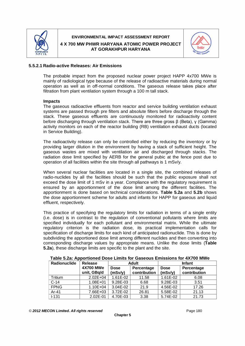
ENVIRONMENTAL IMPACT ASSESSMENT REPORT
4 X 700 MW PHWR HARYANA ATOMIC POWER PROJECT AT GORAKHPUR HARYANA
© 2012 MECON Limited. All rights reserved Page 180
Chapter 5
5.5.2.1 Radio-active Releases: Air Emissions The probable impact from the proposed nuclear power project HAPP 4x700 MWe is mainly of radiological type because of the release of radioactive materials during normal operation as well as in off-normal conditions. The gaseous release takes place after filtration from plant ventilation system through a 100 m tall stack. Impacts The gaseous radioactive effluents from reactor and service building ventilation exhaust systems are passed through pre filters and absolute filters before discharge through the stack. These gaseous effluents are continuously monitored for radioactivity content before discharging through ventilation stack. There are three gross β (Beta), γ (Gamma) activity monitors on each of the reactor building (RB) ventilation exhaust ducts (located in Service Building). The radioactivity release can only be controlled either by reducing the inventory or by providing larger dilution in the environment by having a stack of sufficient height. The gaseous wastes are mixed with ventilation air and discharged through stacks. The radiation dose limit specified by AERB for the general pubic at the fence post due to operation of all facilities within the site through all pathways is 1 mSv/y. When several nuclear facilities are located in a single site, the combined releases of radio-nuclides by all the facilities should be such that the public exposure shall not exceed the dose limit of 1 mSv in a year. Compliance with the regulatory requirement is ensured by an apportionment of the dose limit among the different facilities. The apportionment is done based on technical considerations. Table 5.2a and 5.2b shows the dose apportionment scheme for adults and infants for HAPP for gaseous and liquid effluent, respectively. This practice of specifying the regulatory limits for radiation in terms of a single entity (i.e. dose) is in contrast to the regulation of conventional pollutants where limits are specified individually for each pollutant and environmental matrix. While the ultimate regulatory criterion is the radiation dose, its practical implementation calls for specification of discharge limits for each kind of anticipated radionuclide. This is done by subdividing the apportioned dose limit among different nuclides and then converting into corresponding discharge values by appropriate means. Unlike the dose limits (Table 5.2a), these discharge limits are specific to the plant and the site.
Table 5.2a: Apportioned Dose Limits for Gaseous Emissions for 4X700 MWe
Adult Infant Radionuclide Release 4X700 MWe unit, GBq/d
Dose (mSv/y)
Percentage contribution
Dose (mSv/y)
Percentage contribution
Tritium 2.02E+04 1.61E-02 11.58 1.61E-02 6.08 C-14 1.08E+01 9.28E-03 6.68 9.28E-03 3.51 FPNG 1.10E+04 3.04E-02 21.9 4.56E-02 17.26 Ar-41 7.66E+03 3.72E-02 26.81 5.58E-02 21.13 I-131 2.02E-01 4.70E-03 3.38 5.74E-02 21.73
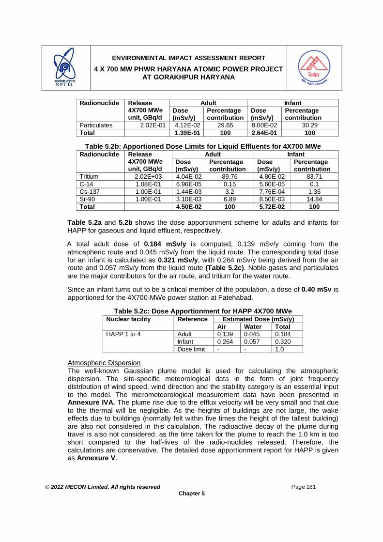
ENVIRONMENTAL IMPACT ASSESSMENT REPORT
4 X 700 MW PHWR HARYANA ATOMIC POWER PROJECT AT GORAKHPUR HARYANA
© 2012 MECON Limited. All rights reserved Page 181
Chapter 5
Adult Infant Radionuclide Release 4X700 MWe unit, GBq/d
Dose (mSv/y)
Percentage contribution
Dose (mSv/y)
Percentage contribution
Particulates 2.02E-01 4.12E-02 29.65 8.00E-02 30.29 Total 1.39E-01 100 2.64E-01 100
Table 5.2b: Apportioned Dose Limits for Liquid Effluents for 4X700 MWe
Adult Infant Radionuclide Release 4X700 MWe unit, GBq/d
Dose (mSv/y)
Percentage contribution
Dose (mSv/y)
Percentage contribution
Tritium 2.02E+03 4.04E-02 89.76 4.80E-02 83.71 C-14 1.08E-01 6.96E-05 0.15 5.60E-05 0.1 Cs-137 1.00E-01 1.44E-03 3.2 7.76E-04 1.35 Sr-90 1.00E-01 3.10E-03 6.89 8.50E-03 14.84 Total 4.50E-02 100 5.72E-02 100
Table 5.2a and 5.2b shows the dose apportionment scheme for adults and infants for HAPP for gaseous and liquid effluent, respectively.
A total adult dose of 0.184 mSv/y is computed, 0.139 mSv/y coming from the atmospheric route and 0.045 mSv/y from the liquid route. The corresponding total dose for an infant is calculated as 0.321 mSv/y, with 0.264 mSv/y being derived from the air route and 0.057 mSv/y from the liquid route (Table 5.2c). Noble gases and particulates are the major contributors for the air route, and tritium for the water route. Since an infant turns out to be a critical member of the population, a dose of 0.40 mSv is apportioned for the 4X700-MWe power station at Fatehabad.
Table 5.2c: Dose Apportionment for HAPP 4X700 MWe
Estimated Dose (mSv/y) Nuclear facility Reference Air Water Total
Adult 0.139 0.045 0.184 Infant 0.264 0.057 0.320
HAPP 1 to 4
Dose limit - - 1.0
Atmospheric Dispersion The well-known Gaussian plume model is used for calculating the atmospheric dispersion. The site-specific meteorological data in the form of joint frequency distribution of wind speed, wind direction and the stability category is an essential input to the model. The micrometeorological measurement data have been presented in Annexure IVA. The plume rise due to the efflux velocity will be very small and that due to the thermal will be negligible. As the heights of buildings are not large, the wake effects due to buildings (normally felt within five times the height of the tallest building) are also not considered in this calculation. The radioactive decay of the plume during travel is also not considered, as the time taken for the plume to reach the 1.0 km is too short compared to the half-lives of the radio-nuclides released. Therefore, the calculations are conservative. The detailed dose apportionment report for HAPP is given as Annexure V.

ENVIRONMENTAL IMPACT ASSESSMENT REPORT
4 X 700 MW PHWR HARYANA ATOMIC POWER PROJECT AT GORAKHPUR HARYANA
© 2012 MECON Limited. All rights reserved Page 182
Chapter 5
Once the spatial distribution of radio-nuclides is obtained, the radiation fluxes at receptor locations of interest are obtained by integrating over the volume source with appropriate geometric attenuation factors. The flux to dose conversion is done using standard conversion factors taken from BSS 115. Dose computations for the all the pathways of exposure were made in accordance with procedures described in “Manual on Dose Evaluation from Atmospheric Releases”, BARC-1412”.
For estimation of dose limit at 1.0 km plant boundary, the above considerations and the annual average rate of discharge of gaseous radioactive effluents from all the units of 700 MWe are considered and estimation has been done and the results are shown in Table 5.2d.
The dose limit for the general public due to operation of all facilities within HAPP site is 1 mSv/y. These are further apportioned among the various radio-nuclides (Table 5.2d). Radiological gaseous effluents when averaged over one day shall not exceed ten times the annual average releases rates specified above.
Table 5.2d: Gaseous Radioactive Releases and Corresponding Dose to Members of Public at 1.0 km Exclusion Boundary
Dose at Exclusion Boundary (mSv/y)
Gaseous Radio-active Effluents Stack Release 4X700 MWe unit
GBq/d Adult Infant Tritium 2.02E+04 1.61E-02 1.61E-02 C-14 1.08E+01 9.28E-03 9.28E-03 Fission Product Noble Gases (FPNGs) 1.10E+04 3.04E-02 4.56E-02 Ar-41 7.66E+03 3.72E-02 5.58E-02 I-131 2.02E-01 4.70E-03 5.74E-02 Particulates 2.02E-01 4.12E-02 8.00E-02
Total 1.39E-01 2.64E-01
Mitigation Measures Design of the plant is based on minimizing the leakages from the plant system in to
plant buildings so that generation of radioactive effluents is minimized. The gaseous radioactive effluents from reactor and service building ventilation
exhaust systems are passed through pre filters and absolute filters before discharge through the ventilation stack.
The gaseous effluents are continuously monitored for radioactivity content before discharging through ventilation stack. Otherwise the ventilation stack is meant only for handling the ventilation exhaust of different units. There are three gross β (Beta), γ (Gamma) activity monitors on each of the reactor building (RB) ventilation exhaust ducts (located in Service Building)
5.5.2.2 Radio-active Releases: Liquid Effluent Discharges
General In atomic power plant water is required for:
Making up the losses in the waste heat disposal systems Input for domestic water requirements Radioactive waste dilution

ENVIRONMENTAL IMPACT ASSESSMENT REPORT
4 X 700 MW PHWR HARYANA ATOMIC POWER PROJECT AT GORAKHPUR HARYANA
© 2012 MECON Limited. All rights reserved Page 183
Chapter 5
Waste heat from the non-safety related loads like condenser and auxiliaries is dissipated using Natural Draught Cooling Towers (NDCTs) and heat from the safety related loads is dissipated using Induced Draught Cooling Towers (IDCTs). Radioactivity in liquid effluents from PHWRs is mainly due to tritium and other activation products in moderator and coolants - at very low concentrations. Dilution is the only treatment for tritium discharge to environment. Regulatory stipulation demands that the radioactivity levels in the liquid effluents should be within limits such that the apportioned dose for the general public utilizing the water at the discharge point is not exceeded. A common liquid effluent discharge scheme has been envisaged for HAPP 1 to 4 (Fig. 2.10). After using the water for the required purpose, both the treated active and inactive water will be discharged into Fatehabad branch of Bhakra Canal. Total estimated plant drain water quantity is about 5320 m3/hr. This includes the blow-own from NDCTs, IDCTs and other miscellaneous plant drains. The total water requirement of HAPP 1 to 4 units is 18000 m3/hr, out of which about 12680 m3/hr is for consumptive usage. About 5320 m3/hr is waste water discharge from plant which is used as dilution water for HAPP 1 to 4. The same is available from NDCT/IDCT blow-down and Plant Water Treatment Water (PTP) drains (Fig. 2.13). Impacts In an Atomic Power Plant waste water is generated from different waste streams as given Table 5.2a. The wastes from different streams may contain radioactivity levels as shown in Table
5.2a, which if discharged in to receiving water bodies may cause radiation exposure to downstream users of the canal water and to the biotic environment of the canal water.
Substantial heat is generated during the process and water is used as one of the coolants. For HAPP closed loop cooling tower are used hence there will not be any discharge of heated effluent to the receiving water body.
Sewage effluents from plant and township may contaminate the receiving water bodies.
Table 5.2a: Waste Water Discharges
Activity Levels (Bq/ml)
Activity Inventory Waste stream Quantity m³/day
Gross β-γ
Tritium Gross β-γ (KBq)
Tritium (MBq)
Treatment
1.0 Potentially Active Waste (PAW) Showers 30 3.7E-3 250 111 7500 Washings 20 3.7E-2 250 740 5000 Laundry 25 3.7E-1 100 10360 2500 Total low radioactive Effluent Discharge to be diluted
75
Filtration, dilution with plant water drainage system and discharged to Bhakra canal. Total discharge 5320 m3/hr.

ENVIRONMENTAL IMPACT ASSESSMENT REPORT
4 X 700 MW PHWR HARYANA ATOMIC POWER PROJECT AT GORAKHPUR HARYANA
© 2012 MECON Limited. All rights reserved Page 184
Chapter 5
Activity Levels (Bq/ml)
Activity Inventory Waste stream Quantity m³/day
Gross β-γ
Tritium Gross β-γ (KBq)
Tritium (MBq)
Treatment
2.0 Active Non-Chemical Waste (ANCW)
12 1.85 1850 22200 2220 Filtration, polishing through IX column, evaporation, dilution with exhausts air and discharged through stack.
3.0 Tritiated Waste (TTW) Moderator room sump
2 1.85 11E4 3700 222000
D2O upgrading plant 6 0.371 7.4E4 2220 444000 - Do -
4.0 Active Chemical Waste (ACW)
1 1850 18500 Occasional Occasional Neutralized & treated like ANCW.
5.0 Organic Waste 13.7 litre / day
0.037 1850 Occasional Occasional Filtration, dilution with plant water drainage system and discharged to Bhakra canal. Total discharge 5320 m3/hr.
Total 96.01 39331 683220 Mitigation Measures Design of the plant is based on minimizing the leakages from the plant system in to
plant buildings so that generation of radioactive effluents is minimized. In addition waste management facilities will be set up to treat the different levels of radioactive effluents to meet the authorized release limits stipulated by AERB. Further, the effluents will be mixed with the blow-down water from cooling tower (NDCTs, IDCTs and other miscellaneous plant drains) to provide the required dilution at the point of discharge to meet the AERB limits.
As given in Table 5.2a only the Potentially Active Waste (PAW) to the tune of 75 m3/day, of low level radioactive waste will be diluted to well below prescribed AERB norms will be the main effluent to be discharged into the Fatehabad Branch of Bhakra Canal.
The total waste water to be discharged from HAPP in to Fatehabad Branch of Bhakra Canal will be 5320 m3/hr.
The diluted low radioactive waste before discharged to Fatehabad Branch of Bhakra Canal will be continuously monitored for radioactivity.
A Main Outfall (MOF) sampling system at the downstream of treated waste injecting point in plant water discharge system will be provided - to further ensure that the liquid waste discharges made from waste management plant (WMP) have been adequately diluted with plant water discharge system and are within the permissible discharge limits. This sampling will be done continuously over a period of 24 hours. These samples will be analyzed in the laboratory for tritium and gross beta activity.
Rest of the liquid effluent (Table 5.2a) having relatively high tritium and Beta gamma activity like Tritiated Waste (TTW) generated from Upgrading plant rejects, Moderator room sump & Clean-up system and Active Non Chemical Waste (ANCW) generated from Equipment decontamination system of WMP, chemical laboratory &

ENVIRONMENTAL IMPACT ASSESSMENT REPORT
4 X 700 MW PHWR HARYANA ATOMIC POWER PROJECT AT GORAKHPUR HARYANA
© 2012 MECON Limited. All rights reserved Page 185
Chapter 5
SFSB cask wash down area, of less volume (21.01 m3/day) will be treated and evaporated [in Induced Draught Cooling Towers (IDCTs)] after dilution with exhaust air and will be discharged through stack to air route. Liquid effluent to the tune of 21.01 m3/day having relativity higher activity are treated by filtration and ion exchange process and disposed through air route using Evaporation system. Streams like ANCW, ACW and TTW, after filtration, will be diverted to a synthetic ion exchange column to remove the dissolved Beta-gamma activity and then stored in evaporation system feed tank. These polished tritium bearing liquid waste streams (free of gross beta activity) are sent to a steam heated evaporator with a controlled flow rate of 1.4 m³/hr. This vaporized stream is then injected into the ventilation exhaust ducting leading to 100 m high stack. Evaporation of effluents having relatively higher level of activity ensures the discharges through water route are kept at minimum. The air route mode of disposal offers unique advantage of higher release limits per unit of dose allocation as compared to liquid route. This mode of disposal suits inland site where water body is scarce and extensively used by the surrounding population.
Periodical monitoring of receiving water body water quality at up-gradient and down gradient of the effluent discharge point.
5.5.2.3 Radio-active Releases: Solid Waste Disposal
General
Radioactive solid waste generated at HAPP will be segregated at source depending upon its nature (compactable / non-compactable) and surface dose rate. Different types of radioactive solid wastes generated during the operation are spent ion-exchange resins, paper-waste, cotton waste, air filter, liquid filter, shoe covers, hand gloves, mops, discarded clothing and components, sludge etc. Solid wastes will be transported to Waste Management Plant (WMP) in shielded containers / casks, if required, for treatment / conditioning. The Conditioning system for solid waste provided in WMP includes processes like: Spent resin management for resins from Primary Heat Transport (PHT) System, Moderator system, End shield cooling system, Calandria vault cooling system, SFSB cooling and purification system, Cementation of liquid filters / sludge and Compaction of compressible wastes. The waste after treatment / conditioning will be disposed off in engineered barriers at the Near Surface Disposal Facility (NSDF), depending upon their surface dose rate: Stone lined earth trenches, RCC vaults / trenches and Tile holes / high integrity containers (HIC). As a matter of practice packages having higher radioactivity will be disposed off at the bottom of trenches/ vaults and will be topped by low level assorted waste packages.

ENVIRONMENTAL IMPACT ASSESSMENT REPORT
4 X 700 MW PHWR HARYANA ATOMIC POWER PROJECT AT GORAKHPUR HARYANA
© 2012 MECON Limited. All rights reserved Page 186
Chapter 5
Impacts Solid waste generated from different units may cause radio-active radiation in the surroundings. The source of radioactive waste generation and the type of treatment and disposal method is given in Table 5.3a. The type, quantity and surface dose rate of radio-active waste generated from 4 x 700 MWe PHWR station is shown in Table 5.3b.
Table 5.3a: Type of Solid Waste Generated and Disposal Mode
SN. Source of Waste Treatment Surface Dose Rate
1 Radioactive Spent Ion-Exchange resin from Primary Heat Transport, Moderator, End shield / Calandria vault cooling & Spent Fuel Storage & Inspection Bay (SFSB) clean-up systems in PWHR type reactors
Fixed in polymer / cement matrix monolithic block so as to prevent the release of radio-nuclides to environment.
Surface dose rate up to 0.01 Sv/hr
2 Spent Liquid Filters from various purification systems, viz. Filter cartridges from systems like SFSB purification, Fuel Handling System (FHS) & WMP
Immobilized by cementation before disposing in RCC trenches.
Surface dose rate up to 0.01 Sv/hr
3 Active sludge from tank bottoms & sump Fixed with cement matrix Surface dose rate up to 0.01 Sv/hr
4 Category-I Solid Waste (soft compactable waste)
Volume Reduction using Baling Press (Compactor) with compaction force up to 70 Te. Volume reduction factor of 5
NA
5 Removable & reusable small equipment, components, pipes, heavy water drums etc. having a maximum size of 600 mm dia. & 3500 mm length
Decontamination system (DC) using ultrasonic cleaning & steam
Surface dose rate up to 0.01 Sv/hr
6 Decontamination of clothing & rubber wears such as lab coats, hand gloves, Shoe cover, coveralls etc
Laundry System Surface dose rate up to 0.01 Sv/hr
7 Low Level Combustible Solid Waste Oil fired incinerator is provided to incinerate organic liquid waste & low level (less than 2mR/hr) combustible solid waste (other than plastic waste).
NA
Table 5.3b: Type, Quantity and Surface Dose Rate of Radio-active Waste Generated from
4x700 MWe PHWR Station SN. Type of Waste Avg. Qty.
(m3/year) Surface Dose Rate Remarks
Compactable waste (before compaction)
i) Assorted Waste
162 ii) Pre-filters 15 iii) HEPA filters 32.75
1.
iv) Charcoal filters 0.15
Category-I

ENVIRONMENTAL IMPACT ASSESSMENT REPORT
4 X 700 MW PHWR HARYANA ATOMIC POWER PROJECT AT GORAKHPUR HARYANA
© 2012 MECON Limited. All rights reserved Page 187
Chapter 5
SN. Type of Waste Avg. Qty. (m3/year)
Surface Dose Rate Remarks
Total i. to iv 210
2. Non-Compactable Waste 20 Category-I Occasionally Cat-II 3. Spent liquid filters 2.0 Category-I,II, IIIA Radiation field (max.) in
PHT Gland filter - 20R/hr
Spent IX Resins columns (200 litres capacity) i) Moderator - 48 nos.
9.6
Radiation field up to 40 R/hr
Generally Cat-IIIA Occasionally Cat-II
ii) PHT - 18 nos 3.6 Radiation field 30 to 50 R/hr
Generally Cat-IIIA Occasionally Cat-IIIB
iii) SFSB - 12 nos 2.4
Radiation field up to 5 R/hr Generally Cat-IIIA Occasionally Cat-II
iv) Calandria vault cooling system -12nos.
2.4
Radiation field up to 2 R/hr
Generally Cat-II
v) End shield cooling system - 3 nos.
0.6
Radiation field up to 200m R/hr
Generally Cat-I
4.
Total i. to v. 18.6 5. Sludges 6 Category-I,II Total for Unit 1 & 2 257 Total for Unit 1 to 4 514 Note : Alpha-bearing waste is not generated at NPPs. Waste containing long lived radio-nuclides will not be disposed at NSDF. It will be sent to Fuel Reprocessing facility.
Size & Life of Radioactive Solid waste Disposal Facility
Adequate Land required for Near Surface Disposal Facility (NSDF) will be allotted during detailed plant layout stage. This requirement will include 50-60 years of operating life, once in life time there are En-massse Coolant Channel Replacement (EMCCR) requirement and decommissioning requirements. Initially the disposal modules of NSDF such as Earth Trenches, RCC Trenches and Tile holes will be made to meet the requirement of approximately 10 years of reactor operation and will be augmented as and when required.
NSDF is designed for 50-60 years of operating life followed by 30 years of instructional control period.
Size of Disposal Modules
1. Earth Trenches : 4m x 4 m x 2 m deep (10 trenches will be constructed initially). 2. RCC Trenches : 32 trenched in one modules. Two modules will be constructed
Initially Size of Trench : 5.885 m x 1.475 m x 3 m deep each.
Incinerator The combustible Category I waste will be combusted in incinerators. The main objective of the incinerator is to minimize the disposal volume in earthen trenches thereby reducing the

ENVIRONMENTAL IMPACT ASSESSMENT REPORT
4 X 700 MW PHWR HARYANA ATOMIC POWER PROJECT AT GORAKHPUR HARYANA
© 2012 MECON Limited. All rights reserved Page 188
Chapter 5
activity ingress into ground water. This is one of the most widely used method for volume reduction of low level combustible waste by which reduction in disposal space and cost reduction in engineered barriers can be achieved. This system will cater to very low level active combustible solid waste like paper-waste, cotton waste, mops, discarded clothing, packing materials etc. Capacity of incinerator: Fuel requirement is about 50 litre/hr. of fuel oil (furnace oil) and the solid waste which can be incinerated at a time is 20 kg/hr. Plastic waste will be fused (melt densification method) in a drum to achieve significant volume reduction. This system will operate only after collecting required volume of waste to optimize the fuel requirement to start the incinerator. Generally 2 to 3 days of operation per month is sufficient. Height of chimney will be 30 metre as per state pollution control board norms. Temperature of flue gas emitted from chimney will be very low as it is passed through two stage water scrubber. The ash and scrubbing water after solidification / embedment in cement will be disposed in RCC trenches. Continuous monitoring system is provided to monitor the gas emitted from the chimney. Considering sulphur content in furnace oil as 4% the SO2 emission from burning of furnace oil in the incinerator will be 1.1 g/sec and this emission will be passed through two stage water scrubbing system and moreover, the incinerator will be run occasionally for 2 to 3 days a month thus the impact on surrounding AAQ will be negligible and thus no further assessment on this aspect has been done. Mitigation Measures Treatment and disposal of radioactive solid waste at the plant is carried out as per
AERB / SG / D-13. Solid wastes after conditioning will be disposed off in the Near Surface Disposal
Facility (NSDF) area in earth trenches / RCC trenches / vaults / tile holes / HIC depending upon their surface dose rate.
A waste assaying will be carried out to assess and record the radioactive content in each conditioned waste packages before disposing them. Name of the vault and their identification will also be recorded.
Packages having higher activity will be disposed off at the bottom of trenches / vaults and will be suitably sealed permanently as per established practices. These data will be utilised to assess the safety aspects of the waste repository.
Necessary geo-hydrological & soil analysis studies for the NSDF site will be carried out to assess the safety of NSDF containing solid waste generated from 50 years of plant operation.
Proper surveillance of Solid Waste Management Facility will be carried out - through bore holes provided all around the NSDF to check the integrity of the engineered
ENVIRONMENTAL IMPACT ASSESSMENT REPORT
4 X 700 MW PHWR HARYANA ATOMIC POWER PROJECT AT GORAKHPUR HARYANA
© 2012 MECON Limited. All rights reserved Page 189
Chapter 5
barriers through periodic water sampling. Additional array of boreholes will be provided, whenever the capacity of the facility will be augmented.
The NSDF area will be fenced and necessary access control procedures will be established.
The dose rate on the top of the sealed earth trenches and RCC trenches / vaults will not exceed 0.01 mGy/h.
5.5.2.4 Land Environment
Background During power plant operation, there is no effluent discharge on land surface that could affect the physico-chemical, nutrient and microbial characteristics of the soil. Solid wastes will be stored in engineered underground structures so as to prevent the ingress of radioactivity in to ground or ground water. Therefore no adverse impact is anticipated in the normal course. Impacts due to accidental ingress are dealt with in Chapter 9. Impacts The airborne radiation emissions are expected to fall on the soil / ground surface, which may impact the soil processes and its property. But as mentioned earlier the air born radiological emissions will be well within the prescribed limit. Thus deposition of the same on soil will not have any impact on the soil in the surroundings. Overall impact on soil would be insignificant.
Mitigation Measures No solid wastes are discharged outside exclusion zone boundary to the environment and spent fuel is stored in underwater, underground ponds and cooled continuously. It is usually kept in this manner for several months to a few years and later taken up for reprocessing on batch to batch basis. The radiological emissions through the air, water and solid wastes will be well within the prescribed norms and there will be limited discharge of conventional air and water pollutants during the plant operations. Thus a change in aquatic and terrestrial ecological features is not anticipated.
Decommissioning activity may also result in radioactive effluents. However, the same will be done strictly as per the guidelines of AERB and thus no adverse impact is anticipated.
5.5.3 Conventional Pollutants During Plant Operation 5.5.3.1 Air Environment
No direct use of fossil fuel in the plant process. The high speed diesel for testing / operation of emergency diesel generator sets will be used. Nuclear power contributes very little to atmospheric CO2 or sulphur or nitrogen oxide levels. On an average around 8 grams of CO2/KWh is released.
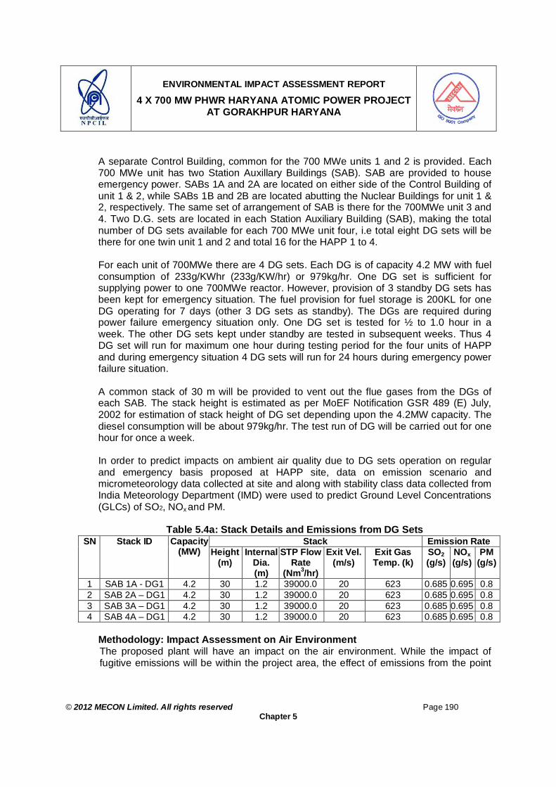
ENVIRONMENTAL IMPACT ASSESSMENT REPORT
4 X 700 MW PHWR HARYANA ATOMIC POWER PROJECT AT GORAKHPUR HARYANA
© 2012 MECON Limited. All rights reserved Page 190
Chapter 5
A separate Control Building, common for the 700 MWe units 1 and 2 is provided. Each 700 MWe unit has two Station Auxillary Buildings (SAB). SAB are provided to house emergency power. SABs 1A and 2A are located on either side of the Control Building of unit 1 & 2, while SABs 1B and 2B are located abutting the Nuclear Buildings for unit 1 & 2, respectively. The same set of arrangement of SAB is there for the 700MWe unit 3 and 4. Two D.G. sets are located in each Station Auxiliary Building (SAB), making the total number of DG sets available for each 700 MWe unit four, i.e total eight DG sets will be there for one twin unit 1 and 2 and total 16 for the HAPP 1 to 4. For each unit of 700MWe there are 4 DG sets. Each DG is of capacity 4.2 MW with fuel consumption of 233g/KWhr (233g/KW/hr) or 979kg/hr. One DG set is sufficient for supplying power to one 700MWe reactor. However, provision of 3 standby DG sets has been kept for emergency situation. The fuel provision for fuel storage is 200KL for one DG operating for 7 days (other 3 DG sets as standby). The DGs are required during power failure emergency situation only. One DG set is tested for ½ to 1.0 hour in a week. The other DG sets kept under standby are tested in subsequent weeks. Thus 4 DG set will run for maximum one hour during testing period for the four units of HAPP and during emergency situation 4 DG sets will run for 24 hours during emergency power failure situation. A common stack of 30 m will be provided to vent out the flue gases from the DGs of each SAB. The stack height is estimated as per MoEF Notification GSR 489 (E) July, 2002 for estimation of stack height of DG set depending upon the 4.2MW capacity. The diesel consumption will be about 979kg/hr. The test run of DG will be carried out for one hour for once a week. In order to predict impacts on ambient air quality due to DG sets operation on regular and emergency basis proposed at HAPP site, data on emission scenario and micrometeorology data collected at site and along with stability class data collected from India Meteorology Department (IMD) were used to predict Ground Level Concentrations (GLCs) of SO2, NOx and PM.
Table 5.4a: Stack Details and Emissions from DG Sets Stack Emission Rate SN Stack ID Capacity
(MW) Height (m)
Internal Dia. (m)
STP Flow Rate
(Nm3/hr)
Exit Vel. (m/s)
Exit Gas Temp. (k)
SO2 (g/s)
NOx (g/s)
PM (g/s)
1 SAB 1A - DG1 4.2 30 1.2 39000.0 20 623 0.685 0.695 0.8 2 SAB 2A – DG1 4.2 30 1.2 39000.0 20 623 0.685 0.695 0.8 3 SAB 3A – DG1 4.2 30 1.2 39000.0 20 623 0.685 0.695 0.8 4 SAB 4A – DG1 4.2 30 1.2 39000.0 20 623 0.685 0.695 0.8
Methodology: Impact Assessment on Air Environment
The proposed plant will have an impact on the air environment. While the impact of fugitive emissions will be within the project area, the effect of emissions from the point
ENVIRONMENTAL IMPACT ASSESSMENT REPORT
4 X 700 MW PHWR HARYANA ATOMIC POWER PROJECT AT GORAKHPUR HARYANA
© 2012 MECON Limited. All rights reserved Page 191
Chapter 5
sources is a major concern as it will have an impact on the ambient air quality in the surrounding area.
For prediction of impacts for any proposed project vis-a-vis to assess the impacts due to increase in pollution load, in general, contributions from the proposed units is added to the existing back ground AAQ concentrations and predictions is done accordingly.
Once the pollutants are emitted into the atmosphere, the dilution and dispersion of the pollutants are controlled by various meteorological parameters like wind speed and direction, ambient temperature, mixing height, etc. In most dispersion models the relevant atmospheric layer is that nearest to the ground, varying in thickness from several hundred to a few thousand meters. Variations in both thermal and mechanical turbulence and in wind velocity are greatest in the layer in contact with the surface. The atmospheric dispersion modeling and the prediction of ground level pollutant concentrations has great relevance in the following activities:
- Estimation of impact of setting up of new industry on surrounding environment. - Estimation of maximum ground level concentration and its location in the study area. The prediction of Ground level concentrations (GLC) of pollutants emitted from the stacks have been carried out using ISCST-3 Air Quality Simulation model released by USEPA which is also accepted by Indian statutory bodies. This model is basically a Gaussian dispersion model which considers multiple sources. The model accepts hourly meteorological data records to define the conditions of plume rise for each source and receptor combination for each hour of input meteorological data sequentially and calculates short term averages up to 24 hours. The impact has been predicted over a 10 km X 10 km area with the proposed location of the stack as the centre. GLC have been calculated at every 500 m grid point. Accordingly, the emissions are estimated and the details of the proposed stacks and emissions from them are given in Table 5.4a. Stack details like height, top diameter, exit velocity etc of all the stacks are taken from similar facilities. However, these stack details may be changed at the detailed engineering stage and as per design of know-how supplier, prevailing emission factors as available in literature for DG sets and different statutory regulations prevailing in the country. Meteorological data plays an important role in computation of Ground Level Concentration using ISCST-3 model. Meteorological data of the project site is another input required for computation of the contribution by the proposed plant. The parameters required are:
Wind velocity and direction Stability Mixing height

ENVIRONMENTAL IMPACT ASSESSMENT REPORT
4 X 700 MW PHWR HARYANA ATOMIC POWER PROJECT AT GORAKHPUR HARYANA
© 2012 MECON Limited. All rights reserved Page 192
Chapter 5
Data related to wind velocity and direction were generated during the monitoring period. Part of this site specific monitored data have been used as input data of the model during computation. The hourly occurrence of various stability classes at the project site is also an important input parameter to the model. Further site specific mixing depth (mixing height or convective stable boundary layer and inversion height or nocturnal stable boundary layer) is also an important input parameter for computation and assessment of realistic dispersion of pollutants. There are different methods for generating these parameters, but in the present case data published by CPCB in Spatial distribution of hourly mixing depth over Indian region have been used. The input meteorological data used in the computation are presented in Table 5.4b and uniform Cartesian grid system was used to locate/fix sources and receptors in the study area. The predicted GLC values are given in Table 5.4c. The above computation is considering the stack emissions only and does not take into account any changes in the fugitive emission. However, since the fugitive emissions are being released mainly from near ground sources, are not expected to travel / disperse to a longer distance to reach beyond the plant boundary and thus are not expected to have any impact on the ambient air. As stated earlier that out of the total sixteen DG sets only four will be in use and rest 12 will on standby. Thus at a time of test run or during emergency situation only four DG sets will run. As a conservative approach the worst scenario prediction were done for the two scenarios, as follows: Scenario 1: When 4 DG sets are running for 1 hour per week for test run. Scenario 2: When in emergency situation in case there is a power failure – 4 DG set runs for 24hrs. For the above two scenarios, ISCST3 model is used to predict the GLCs for operation of four DG sets as per the above two scenarios.
Table 5.4b: Meteorological Data used as Input for Air Quality Modeling Hour Wind Speed
(m/s) Ambient Air Temp. (K)
Predominant Wind Direction (N as 1800)
Hourly Stability Class
Mixing Depth (m)
01 1 294.5 360 6 50 02 1 294.5 315 6 50 03 1 293.4 315 6 40 04 1 292.9 315 6 40 05 1 291.7 360 5 30 06 1 290.5 360 4 80 07 1 290.4 315 3 100 08 1 290.4 315 3 275 09 1 291 315 2 510 10 1 295.4 315 2 800 11 2 300.9 315 1 1300 12 3 304.4 315 1 1500

ENVIRONMENTAL IMPACT ASSESSMENT REPORT
4 X 700 MW PHWR HARYANA ATOMIC POWER PROJECT AT GORAKHPUR HARYANA
© 2012 MECON Limited. All rights reserved Page 193
Chapter 5
Hour Wind Speed (m/s)
Ambient Air Temp. (K)
Predominant Wind Direction (N as 1800)
Hourly Stability Class
Mixing Depth (m)
13 3 305.4 315 2 1600 14 2 306.5 315 3 1750 15 3 307.5 315 3 1850 16 2 308.6 315 3 1700 17 1 308.6 293 4 1500 18 1 308.9 293 4 1300 19 1 306.8 270 5 900 20 1 304 315 5 725 21 1 303.3 315 5 300 22 1 301.8 270 5 200 23 1 301 270 6 100 24 1 299.7 315 6 50
1= Extremely Unstable, 2= Moderately Unstable, 3= Slightly Unstable, 4 = Neutral, 5= Slightly Stable, 6= Moderately Stable Results: Impact on Air Environment
The resultant ambient air concentrations after the setting up atomic power plant if the DG sets are run for 24 hrs continuously has been presented in Table 5.4c for PM, SO2 & NOx and that if run for one hour in a week is presented in Table 5.4d. The isopleths for dispersion values for one hour running of DG sets are not shown as the change in AAQ will be for very short duration during one hour testing of DG sets. However, the Isopleths of 24hr continuous running of DG sets for SO2, NOx and SPM are presented in Fig. 5.2a, 5.2b & 5.2c, respectively. It can be seen that all the respective values of different parameters are well within the National Ambient Air Quality norms. Under this scenario also it may be noted that even running of DG sets for 24 hours is also not a regular feature of the project and will only happen in worst scenario when electric supply is disrupted for 24 hours continuously. Thus it is anticipated that there will not be any adverse changes in AAQ in the study area due to the proposed project.
Table 5.4c Expected Ambient Air Quality after proposed plant
Pollutants Monitored C98 (µg/m3)
Anticipated Maximum contribution of pollutants in µg/m3 due to proposed plant (maximum GLC occurrence co-ordinate)
AAQ after proposed plant
(µg/m3) Four DG sets of 4.2 MW capacity each during emergency running continuously for 24 hrs
RPM 87.0 1.5 (18, 2.5km) 88.5 SO2 19.0 1.29 (17, 2.5km) 20.3 NOx 40.0 1.3 (17, 2.5km) 41.3
*Concentrations are in µg/m3 and of 24 hours averaging time. Values in the parenthesis indicate the coordinates of the grid points in Km (10, 10 km) is the centre of the plant.
. Table 5.4d: Expected Ambient Air Quality for One Hour when DG Sets Running for
One Hour / Week Pollutants During day time (ug/m3) During Night time(ug/m3)
SO2 4.2 (10.5,9.5)km 4.79 (10, 1)km NOx 4.3 (10.5,9.5)km 4.86 (10, 1)km SPM 4.95 (10.5,9.5)km 5.6 (10, 1)km

ENVIRONMENTAL IMPACT ASSESSMENT REPORT
4 X 700 MW PHWR HARYANA ATOMIC POWER PROJECT AT GORAKHPUR HARYANA
© 2012 MECON Limited. All rights reserved Page 194
Chapter 5
Mitigation Measures Nuclear power contributes very little to atmospheric CO2 or sulphur or nitrogen oxide or particulate matter from process. During the design phase all efforts have been made to adopt latest state of art technology and to install adequate pollution control measures and for possible fugitive emission sources. The following mitigation measures will be employed during operation period to reduce the pollution level to acceptable limits: To ensure that all the pollution control facilities envisaged at the design stage are
have been implemented and are functioning properly. Stack monitoring to ensure proper functioning of different pollution control facilities
attached to major stacks. Air monitoring in the Work-zone to ensure proper functioning of fugitive emission
control facilities. Adequate plantation in and around different units. Vehicles and machineries would be regularly maintained so that emissions confirm
to the applicable standards. Monitoring of ambient air quality through online AAQ monitoring system at three
locations and through manual means at three locations (once in a year). Workers will be provided with adequate protective measures to protect them from
inhaling dust. The test running of all the four DG sets for one hour in a week will not be taken up
collectively at a time. Only one DG set will be tested at a time for one hour and remaining three will be taken up in subsequent hour / day of the week.
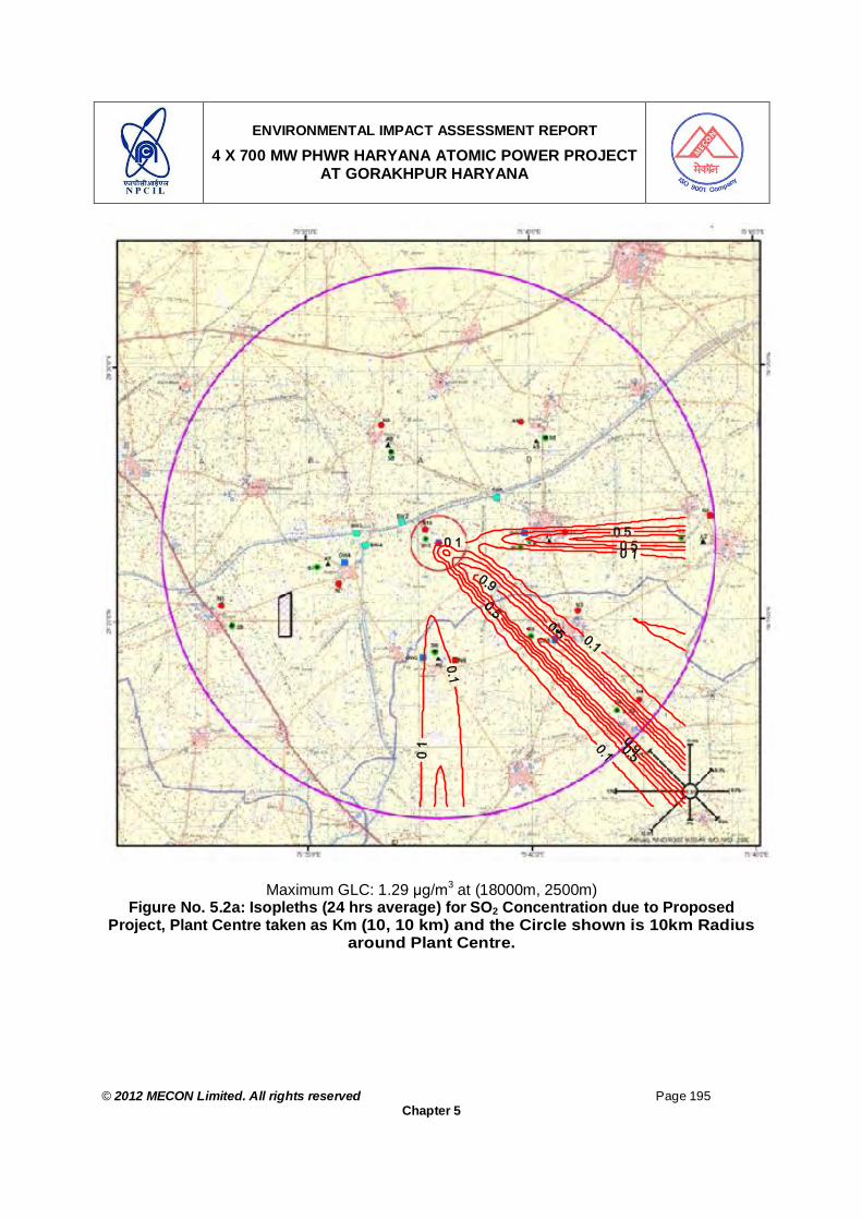
ENVIRONMENTAL IMPACT ASSESSMENT REPORT
4 X 700 MW PHWR HARYANA ATOMIC POWER PROJECT AT GORAKHPUR HARYANA
© 2012 MECON Limited. All rights reserved Page 195
Chapter 5
Maximum GLC: 1.29 µg/m3 at (18000m, 2500m) Figure No. 5.2a: Isopleths (24 hrs average) for SO2 Concentration due to Proposed
Project, Plant Centre taken as Km (10, 10 km) and the Circle shown is 10km Radius around Plant Centre.

ENVIRONMENTAL IMPACT ASSESSMENT REPORT
4 X 700 MW PHWR HARYANA ATOMIC POWER PROJECT AT GORAKHPUR HARYANA
© 2012 MECON Limited. All rights reserved Page 196
Chapter 5
Maximum GLC: 1.3 µg/m3 at (18000m, 2500m)
Figure No. 5.2b: Isopleths (24 hrs average) for NOx Concentration Due to Proposed Project, Plant Centre taken as Km (10, 10 km) and the Circle shown is 10km Radius
around Plant Centre.
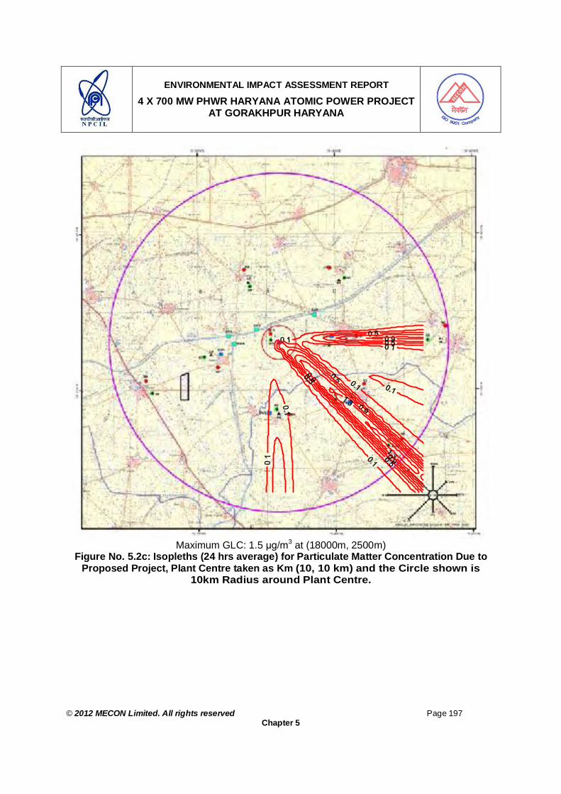
ENVIRONMENTAL IMPACT ASSESSMENT REPORT
4 X 700 MW PHWR HARYANA ATOMIC POWER PROJECT AT GORAKHPUR HARYANA
© 2012 MECON Limited. All rights reserved Page 197
Chapter 5
Maximum GLC: 1.5 µg/m3 at (18000m, 2500m)
Figure No. 5.2c: Isopleths (24 hrs average) for Particulate Matter Concentration Due to Proposed Project, Plant Centre taken as Km (10, 10 km) and the Circle shown is
10km Radius around Plant Centre.
ENVIRONMENTAL IMPACT ASSESSMENT REPORT
4 X 700 MW PHWR HARYANA ATOMIC POWER PROJECT AT GORAKHPUR HARYANA
© 2012 MECON Limited. All rights reserved Page 198
Chapter 5
5.5.3.2 Water Environment
Water environment may be affected by the proposed project in different ways. The water environment may be surface or ground water or both. Water environment may be affected by the industry due to drawl of water, discharge of polluted water / waste water, by contaminated leachate from land disposal / dumping of solid waste, and by change in drainage pattern of the area. The present activities are scrutinized in light of the above factors and its impact is predicted accordingly. Effect of Water Drawl (Surface water and Ground water) on Water Regime Impacts During construction phase - for construction and other miscellaneous uses 1000m3/day of water will be drawn during the construction phase of the proposed project from Fatehabad Branch of Bhakra canal, which is having sufficient water for supply to the proposed project and thus no impact is envisaged on the water supply and users of Fatehabad Branch of Bhakra canal. During operation phase - the proposed plant draws its raw water requirement from plant makeup storage reservoir which in turn receives water from Fatehabad Branch of Bhakra canal. Water is supplied to the plant for different activities from the reservoir directly. In addition to this, water is also supplied to the plant from the reservoir after treating it in a water treatment plant. Consent for allocation of 32652 m3/hr of water for the proposed project from the Fatehabad Branch of Bhakra canal has been assured by the State Government (Annexure III). No ground water will be drawn for the project, thus the impact on ground water due to drawl of ground water by the proposed project is not envisaged. Mitigation Measures No impact envisaged on water regime is envisaged. Various water conservation schemes envisaged to reuse the wastewater generated
in the plant are : - Blow down water from power plant from cooling tower (NDCTs, IDCTs and other
miscellaneous plant drains) will be mixed with low radioactive waste to provide the required dilution at the point of discharge to meet the AERB limits.
In addition, rain water harvesting and monitoring of ground water levels in and around the area of the proposed project will be done.
The sewage from township will be treated in sewage treatment plant and will be used for gardening purposes and the excess will be discharged to out of the township. The discharge sewage will meet the respective MOE&F norm. Total sewage generated from township will be about 34 m3/hr or 816 KLD per day and from plant will be 3.5m3/hr or 100 KLD per day. The two will be used for green belt development in the respective areas.

ENVIRONMENTAL IMPACT ASSESSMENT REPORT
4 X 700 MW PHWR HARYANA ATOMIC POWER PROJECT AT GORAKHPUR HARYANA
© 2012 MECON Limited. All rights reserved Page 199
Chapter 5
Flood Analysis: The project site is within 10 km radius of Bhakra Canal. The Fatehabad Branch of Bhakra Canal is fully lined and hence there is very low probability of canal breach. The flood analysis report is attached as Annexure II. The flood analysis report is briefed under Section 5.4.2. Water Usage
Background In an Atomic Power Plant wastewater may be generated from different units / shops. The liquid waste streams generated from the plant are segregated at source and are collected in collection storage tanks located in Liquid Effluent Segregation System (LESS) area. The waste management design philosophy is based on the principle of ALARA (As low As Reasonably Achievable). The impact and mitigation measures for radioactive liquid waste are given under Section 5.5.2.2.
Impacts Substantial heat is generated during the process and water is used as one of the
coolants. For HAPP closed loop cooling tower are used hence there will not be any discharge of heated effluent to the receiving water body.
Sewage effluents from pant and township may contaminate the receiving water bodies.
Mitigation Measures Thermal pollution: The closed loop cooling towers will be used, which will reduce the
possibility of discharge of thermal pollution to the aquatic environment of receiving water body. No thermal effluents are discharged into water bodies at any stage of the project.
A sewage treatment plant with zero discharge is envisaged for both township as well as project area.
Effluent from DM plant is led to the STP after adequate neutralisation and settling. Treated sewage effluents are recycled to the extent possible for green belt, lawn and horticulture and road dust suppression.
The excess remaining treated sewage is dispersed over land during non-rainy season.
However, during rainy season the treated sewage will be discharged to nearby surface drains in the area, which will be meeting the surface water discharge criteria of CPCB.
In the light of the above no significant change in the physico-chemical properties and ecological features of the receiving water bodies is expected.
Periodical monitoring of receiving water body water quality at up-gradient and down gradient of the effluent discharge point.

ENVIRONMENTAL IMPACT ASSESSMENT REPORT
4 X 700 MW PHWR HARYANA ATOMIC POWER PROJECT AT GORAKHPUR HARYANA
© 2012 MECON Limited. All rights reserved Page 200
Chapter 5
Ground Water
Impacts For construction and other miscellaneous uses 1000m3/day of water will be drawn during the initial phase of the proposed project from Fatehabad Branch of Bhakra canal. Hence no impact on ground water availability around the plant is anticipated. The waste disposal area around any industry is one of the major factors deteriorating ground water quality, if the water leached from the waste dumps contains toxic substances. At the proposed plant, all wastes are dumped in secured land fill sites and only inert wastes, like sludge from sewage treatment plant of township is used for gardening purposes. All other solid wastes containing radio-activity elements are handled and dumped as per the guidelines of AERB. Mitigation Measures Periodical monitoring of ground water quality at up-gradient and down gradient of the
plant area. Disposal of waste generated from the proposed project will be done in a systematic /
scientific manner as per guidelines of AERB to prevent any ground water pollution. 5.5.3.3 Area Drainage and Surroundings
Impact The project may disrupt the natural drainage of the area and surroundings. The area is semiarid with low rainfall and flat terrain without any well defined natural
drainage system. There are no natural drainage channels passing through project and township areas. The general slope of the project site is away from canal to south direction. The drainage is of inland type and the excess rainwater, accumulates in natural /artificial depressions.
Mitigation Measures Impact on drainage of the area is not anticipated. A detailed site topographic survey of the project site and surroundings will be
undertaken and the site features will be so designed that the area and surrounding drainages are not obstructed.
The power project and the township will have their separate storm water drainage systems, designed for the rainfall and drainage of the area. The storm water drainage from the project and township will be led to the Bhakra canal to avoid flooding of the surrounding.
No construction / dumping activities will be done for establishment and operation of the proposed project so as to disrupt the drainage pattern of the area.
Any adverse impact on the drainage pattern of the area is not anticipated.
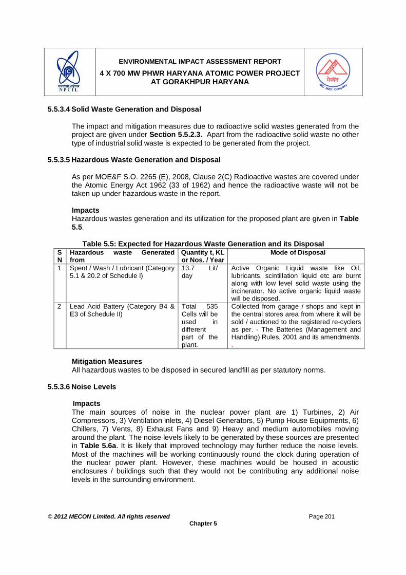
ENVIRONMENTAL IMPACT ASSESSMENT REPORT
4 X 700 MW PHWR HARYANA ATOMIC POWER PROJECT AT GORAKHPUR HARYANA
© 2012 MECON Limited. All rights reserved Page 201
Chapter 5
5.5.3.4 Solid Waste Generation and Disposal
The impact and mitigation measures due to radioactive solid wastes generated from the project are given under Section 5.5.2.3. Apart from the radioactive solid waste no other type of industrial solid waste is expected to be generated from the project.
5.5.3.5 Hazardous Waste Generation and Disposal As per MOE&F S.O. 2265 (E), 2008, Clause 2(C) Radioactive wastes are covered under the Atomic Energy Act 1962 (33 of 1962) and hence the radioactive waste will not be taken up under hazardous waste in the report. Impacts Hazardous wastes generation and its utilization for the proposed plant are given in Table 5.5.
Table 5.5: Expected for Hazardous Waste Generation and its Disposal SN
Hazardous waste Generated from
Quantity t, KL or Nos. / Year
Mode of Disposal
1 Spent / Wash / Lubricant (Category 5.1 & 20.2 of Schedule I)
13.7 Lit/ day
Active Organic Liquid waste like Oil, lubricants, scintillation liquid etc are burnt along with low level solid waste using the incinerator. No active organic liquid waste will be disposed.
2 Lead Acid Battery (Category B4 & E3 of Schedule II)
Total 535 Cells will be used in different part of the plant.
Collected from garage / shops and kept in the central stores area from where it will be sold / auctioned to the registered re-cyclers as per. - The Batteries (Management and Handling) Rules, 2001 and its amendments. .
Mitigation Measures All hazardous wastes to be disposed in secured landfill as per statutory norms.
5.5.3.6 Noise Levels
Impacts The main sources of noise in the nuclear power plant are 1) Turbines, 2) Air Compressors, 3) Ventilation inlets, 4) Diesel Generators, 5) Pump House Equipments, 6) Chillers, 7) Vents, 8) Exhaust Fans and 9) Heavy and medium automobiles moving around the plant. The noise levels likely to be generated by these sources are presented in Table 5.6a. It is likely that improved technology may further reduce the noise levels. Most of the machines will be working continuously round the clock during operation of the nuclear power plant. However, these machines would be housed in acoustic enclosures / buildings such that they would not be contributing any additional noise levels in the surrounding environment.

ENVIRONMENTAL IMPACT ASSESSMENT REPORT
4 X 700 MW PHWR HARYANA ATOMIC POWER PROJECT AT GORAKHPUR HARYANA
© 2012 MECON Limited. All rights reserved Page 202
Chapter 5
Table 5.6a: Main Sources of Noise from Different Equipments & their Noise Levels SN. Location of Source Noise level in dB
(A) Distance from
Noise Source (m) 1 Chillier and compressor Room 98 - 105 2 2 Boiler Feed Pump area unit –I 95 2 3 Turbo Generator – 1st Floor 95 – 105 2 4 Boiler Feed pump are unit -2 95 2 5 Turbo Generator – 2nd floor 95- 105 2 6 Up grading Plant 90 -95 2 7 CWPH 90-95 2 8 PWPH 90-93 2 Source : NPCIL Note: 1. All the above-mentioned equipments will be housed in properly designed and engineered
buildings, which will work as protective enclosures. 2. The occupancy of human beings like occupational workers on continuous basis is not
envisaged in the areas around these equipments Prediction of Impacts on Community During the operation phase noise will be generated from different sources. With increasing distance from the source the noise level decreases due to wave divergence. Additional decrease also occurs due to atmospheric effects and interaction with objects in the transmission paths. For hemispherical sound wave propagation through homogeneous medium, one can estimate the noise levels at various locations due to different sources using a model based on the following principle :
Lp2 = Lp1 – 20 Log (r2/r1), where Lp1 and Lp2 are the sound levels at points located at distance r1 and r2 from the source.
Combined effect of all the sources (A,B,C,…. Etc) can be determined at various locations by the following equation :
Lptotal = 10 Log (10lpa/10 + 10lpb/10 + 10lpc/10 …………..), where Lpa, Lpb and Lpc are noise pressure levels at a point due to different sources.
Based on the above principle a Noise Model has been developed in house, which has been used to predict the noise. The noise level contours due to the noise sources in units of the proposed Atomic Power Plant without considering noise barriers are shown in Fig. 5.3. Without any barriers viz. buildings and green belt, it is predicted that the noise levels in the surrounding environment due to above said equipments of the proposed units at a distance of 500 m will be 52 dB(A) and at 1000 m will be 50 dB(A). It is also predicted that the noise levels from these sources at 2000 m distance will be <50 dB(A). Therefore, background noise levels in the nearest village i.e. Gorakhpur located at a distance of 2 km will remain below 50 dB(A).
The maximum noise levels will occur at receptors located near all the proposed units which are predicted to be less than 60 dB(A) without any barriers viz. buildings. These noise levels would be significantly reduced when the barrier of building is considered at the time of operation of plant.

ENVIRONMENTAL IMPACT ASSESSMENT REPORT
4 X 700 MW PHWR HARYANA ATOMIC POWER PROJECT AT GORAKHPUR HARYANA
© 2012 MECON Limited. All rights reserved Page 203
Chapter 5
Considering the attenuation due to specially designed building within which noise generating machineries will be housed, the increase in noise levels will be around 1-2 dB(A) just outside the building of power plant. Thus, there will not be any change in the ambient noise levels due to operation of nuclear power plant in the nearest village Gorakhpur at 2 km distance.
NOISE PRESSURE LVELS
0102030405060
100
200
300
400
500
600
700
800
900
1000
1500
1600
1700
2000
Receptor distance (m)
Nois
e lv
els
in d
B(A
)
Fig 5.3: Predicted Noise Levels due to Noise Sources without Considering Attenuation
due to Barriers Like Building and Greenbelt.
As indicated above there will not be any increase in noise levels due to operation of the proposed project in the nearest village Gorakhpur at 2 km distance. Therefore the community will not be affected by the operation of the APP at Fatehabad.
Moreover, the predicted noises within the plant premises beyond work zone without building will be as given in Table 5.6b.
Table 5.6b : Noise level with in existing plant premises beyond work zone SN. Location Noise Level in dB (A) A Outside Building 1 Near Overhead Tank ( North) 67.7 2 Between TB-I & TB-2 (East) 69 3 Near Pipe Ramp (south) 69 4 Near CAS (West) 62 B Boundary of Operating Island 1 North of operating island 71.3 2 East of Operating Island 66 3 South of Operating Island 66 4 West of Operating Island 61.5
Noise in the work place generated from operation of equipment is the only concern from the point of view of occupational health.

ENVIRONMENTAL IMPACT ASSESSMENT REPORT
4 X 700 MW PHWR HARYANA ATOMIC POWER PROJECT AT GORAKHPUR HARYANA
© 2012 MECON Limited. All rights reserved Page 204
Chapter 5
Prediction of Impact on Occupational Health Equivalent sound pressure level, 8 hrs average, (Leq 8 hrs), is used to describe exposure to noise in workplaces. The damage risk criteria for hearing loss, enforced by Occupational Safety and Health Administration, (OSHA) USA and stipulated by other organizations, is that noise levels up to 90 dB(A) are acceptable for eight hours exposure per day. Ministry of Labour, Government of India has also recommended similar criterion vide Factories Act, Schedule No. XXIV (Government Notification FAC/1086/CR-9/Lab-4, dated 8/2/1988).
The noise levels in the building are predicted to be 90 dB(A). However, the workers in the noise zone area will be provided with protective equipments like ear muffs and as a result the occupational exposure of the workers is reduced considerably within stipulated limits.
Mitigation Measures The noise levels of high speed machinery like compressors, fans and blowers are in the range of 90-110 dB(A). Various measures proposed to reduce noise level at source are, acoustic enclosures, hoods, acoustic lagging for the equipment and suction side silencers, vibration isolators, selection of low noise equipment, isolation of noisy equipment from working personnel. ID and FD fans will be provided with silencers and the fan casing will be properly insulated. So that the sound pressure level exposure in working areas is restricted below 90 dB(A) for 8 hours duty. Noise proof and air conditioned control room will be provided for operators wherever required.
All equipments would be designed / operated to have a noise level not exceeding 85 dBA (A) at a distance of 1m as per the requirement of Occupational Safety and Health Administration Standard (OSHA). In addition, since most of the noise generating equipments would be in closed structures, the noise transmitted outside would be still lower. The presence of an exclusion zone (1km) will serve to insulate whatever little noise is generated. Noise in the work place generated from operation of equipment is the only concern from the point of view of occupational health and the operating experience of other Atomic Power Projects supports this view. The following measures will be undertaken to reduce noise generation from source: Technological Measures
Plugging leakages in high-pressure gas/air pipelines. Reducing vibration of high speed rotating machines by regular monitoring of
vibration and taking necessary steps. Design of absorber system for the shift office and pulpit operator's cabin. Noise absorber systems in pump houses. Noise level at 1m from equipment will be limited to 85 dB (A). The fans and ductwork will be designed for minimum vibration.

ENVIRONMENTAL IMPACT ASSESSMENT REPORT
4 X 700 MW PHWR HARYANA ATOMIC POWER PROJECT AT GORAKHPUR HARYANA
© 2012 MECON Limited. All rights reserved Page 205
Chapter 5
All the equipment in different units will be designed/operated in such a way that the noise level shall not exceed 85 dB (A).
Periodical monitoring of work zone noise and outside plant premises. Management Measures In Atomic Power Plant, with a variety of noise producing equipment, it may not be practicable to take technological control measures at all the places. In such cases the following administrative measures shall also be taken:
Un-manned high noise zone will be marked as “High Noise Zone". In shops where measures are not feasible, attempts shall be made to provide
operators with sound-proof enclosure to operate the system. Workers exposed to noise level will be provided with protection devices like ear
muffs/ ear plugs and will be advised to use them regularly, while at work. Workers exposed to noisy work place shall be provided with rotational duties.
The duration of exposure of the personnel will be limited as per the norms. All workers will be regularly checked medically for any noise related health
problem and if detected, they will be provided with alternative duty. Over and above all these adopted measures, trees and shrubs belts of substantial depths within and surrounding plant premises will further attenuate the sound levels within limits reaching the receptors out side the plant premises.
5.5.3.7 Ecological Features
Impacts Erection and commissioning of the project may change the land-use pattern of the
area and may cause significant loss of habitat / agricultural land, which is unavoidable.
During construction some existing vegetation / crops on the project site may be cut / damaged.
The construction and operation of the project may cause direct impact to the fauna present in the area.
Emissions from plant operation may affect the natural vegetation and agricultural crops around the proposed plant.
The thresh-hold limit for continuous exposure of SO2 on plants is about 50 ug/m3 and that for NOx is 100 ug/m3 (Env. Engg., Chapter 7 by H. S. Pavy, D. R. Rowe, G.T. Chobanoglous. Mc.Graw-Hill Book Co.1986). The level of air pollutants due to DG set operation (only occasionally) will be much below the above said level. Thus it is expected that the natural vegetation in the area will not be affected. So far as agriculture crops are concerned, as they will remain in the field for three to six months only, the impact on the same is also not anticipated.

ENVIRONMENTAL IMPACT ASSESSMENT REPORT
4 X 700 MW PHWR HARYANA ATOMIC POWER PROJECT AT GORAKHPUR HARYANA
© 2012 MECON Limited. All rights reserved Page 206
Chapter 5
There is no forest area within 10km radius of the project site. Thus it is expected that the flora and fauna in the study area will not get affected due to the proposed project.
Noise generated due to the proposed project may cause disturbance to the faunal species.
Strong light in the project premises during night may cause some disturbance to the fauna in the near by areas.
The waste water from plant operation and domestic use may cause surface water pollution in the area.
Mitigation Measures All care will be taken to avoid cutting of trees growing in the project site.
All technological measures to limit air emissions, waste water discharge and noise generation are envisaged in the proposed plant design and hence no further mitigation measures envisaged.
An elaborate green belt / cover already exists which will be further enhanced within and around the plant as detailed in Chapter 6 to ameliorate the fugitive emissions and noise from the project operation.
The domestic waste water will be treated and after treatment the same will be re-used and recycled within the plant itself and only excess water will be discharged which will meeting the statutory norm. Thus there will be no impact on the ecological components of surface water bodies in the area.
Mitigation Measures for Reducing Impacts on Faunal Species
Direct Disturbance: Ten feet high RCC concrete wall fencing is erected all around the project so that no animals come to the project site. Further a green belt erected within the fencing (facing the proposed plant expansion) all around the proposed plant area will further reduce the impact of direct disturbance.
Noise: The maximum noise level reaching out side the proposed plant project boundary will be below the statutory norms for residential and other areas will be below the statutory norm. Further the green belt all along the project boundary will further reduce the noise level so as to cause any disturbance to the faunal species. Thus the animals in the study area will not get impacted due to the noise from the proposed project activity.
Strong Light during Night: The strong light in the project premises during night may cause some disturbance to the fauna in the near by areas. It is proposed that all the light posts erected along the boundary wall will face inwards and down wards (with reflectors facing the plant and downwards), so that the light do not spreads out side the plant boundary.

ENVIRONMENTAL IMPACT ASSESSMENT REPORT
4 X 700 MW PHWR HARYANA ATOMIC POWER PROJECT AT GORAKHPUR HARYANA
© 2012 MECON Limited. All rights reserved Page 207
Chapter 5
5.5.3.8 Transportation : Impacts and Mitigation Measures
It is anticipated that the possible impact due to transportation on the surrounding infrastructure will be only during the construction and operation stage of the project.
Impact
Construction Phase The anticipated average increase in vehicular movement per day during construction phase will be as given in Table 5.7a.
Table 5.7a: Average vehicular movement during construction stage
SN Type of Vehicle Numbers Plying per day
Type of Impact - Plying at Construction site only In the Region
1 Trucks 125 In the Region 2 Cars / Jeeps 30 In the Region 3 Over Sized Consignment 1 In the Region 4 Excavator 2 Construction site only 6 Wagon Drills 8 Construction site only 7 Dozer 80D 2 Construction site only 8 Grader 1 Construction site only 9 Air Compressors 500 CFM Construction site only 10 Drifter 3 Construction site only 11 Dumper
(a) 6m3 Capacity (b) 10m3 Capacity
30 3
Construction site only
12 Poclain (a) 1.5 cum bucket (b) 2.0 cum bucket
6 2
Construction site only
13 Front end loader JCB 2 Construction site only 14 Tractor mounted water tanker &
sprinkler for dust control 5000 liters capacity 2 numbers
Construction site only
15 Magzine Van (10T) 2 Construction site only 16 Portable Magzine 3 Construction site only 17 DG set for batching plant area As required Construction site only 18 Vibratory Road Roller 10 MT 1 Construction site only 19 Crushing plant for normal & heavy
aggregate 100 TPH 1 Construction site only
20 Remix / transit cars 6 cum capacity 3 cum capacity
10 3
Construction site only
A total of maximum 125 trucks (HMV) per day will be running in the region for the construction material requirement of the plant. For traffic volume estimation, considering receipt of construction materials in two shifts (16hrs.) about 8 trucks per hour (in-coming / returning trucks) will be additionally running on the road leading to the project site. Similarly for Cars / Jeeps (LMV) about 2 vehicles will be running in the region for the construction requirement of the plant. It is anticipated that oversized consignment vehicle will be plying at the most one vehicle per day in the region. While other vehicles

ENVIRONMENTAL IMPACT ASSESSMENT REPORT
4 X 700 MW PHWR HARYANA ATOMIC POWER PROJECT AT GORAKHPUR HARYANA
© 2012 MECON Limited. All rights reserved Page 208
Chapter 5
as mentioned under serial number 4 to 9 (Table 5.7a), once moved to the project site will be running at the site only and hence has not been considered further for estimation of enhanced traffic load. The increase in traffic load on NH10 due to the project is shown in Table 5.7b. It can be seen that there will be only 3% increase in the traffic load over the existing traffic volume. However, this increase will be temporary and will be there only during construction stage. Thus it is anticipated that there will be not much impact of the project on existing traffic load. Moreover from air pollution point of view, increase in a maximum of 3% PCU per day will be insignificant. Thus it can be said that impact of vehicular movement due to material and manpower transport on the air environment will not be there.
Table 5.7b: Increase in Traffic Load on NH10 During Construction Phase
Existing# Additional from Plant Operation Total Time Hour PCU Heavy
Motor Vehicles
Cars Two Wheelers
Additional PCU due
to the Project
Final PCU after
Project
6.00 AM to 6.59 A.M 322.5 8 2 0 27 350 7.00 AM to 7.59 A.M 380.5 8 2 0 27 408 8.00 AM to 8.59 A.M 270 8 2 0 27 297 9.00 AM to 9.59 A.M 702.5 8 2 0 27 730 10.00 AM to 10.59 A.M 423.5 8 2 0 27 451 11.00 AM to 11.59 A.M 314 8 2 0 27 341 12.00 AM. to 12.59 PM 289.5 8 2 0 27 317 1.00 PM to 1.59 PM 592.5 8 2 0 27 620 2.00 PM to 2.59 PM 626.5 8 2 0 27 654 3.00 PM to3.59 PM 834.5 8 2 0 27 862 4.00 PM to 4.59 PM 760.5 8 2 0 27 788 5.00 PM to 5.59 PM 728.5 8 2 0 27 756 6.00 PM to 6.59 PM 727.5 8 2 0 27 755 7.00 PM to 7.59 PM 764.5 8 2 0 27 792 8.00 PM to 8.59 PM 806 8 2 0 27 833 9.00 PM to 9.59 PM 776.5 8 2 0 27 804 10.00 PM to 10.59 PM 837.5 0 0 0 0 838 11.00 PM to 11.59 PM 864.5 0 0 0 0 865 12.00 PM to12.59 PM 902 0 0 0 0 902 1.00 AM to 1.59 AM 831.5 0 0 0 0 832 2.00 AM to 2.59 AM 479.5 0 0 0 0 480 3.00 AM to 3.59 AM 388.5 0 0 0 0 389 4.00 AM to 4.59 AM 306.5 0 0 0 0 307 5.00 AM to 5.59 AM 279 0 0 0 0 279 Total Per Day 14208.5 128 32 0 432 14641 % Increase in PCU 3 # From Table 3.16a Passenger Car Unit (PCU) : 3 for HMV, 1.5 for LMV; 0.5 for Two Wheelers as per IRC.

ENVIRONMENTAL IMPACT ASSESSMENT REPORT
4 X 700 MW PHWR HARYANA ATOMIC POWER PROJECT AT GORAKHPUR HARYANA
© 2012 MECON Limited. All rights reserved Page 209
Chapter 5
Operation and Maintenance Phase As there is no bulk transportable finished / waste product from the APP, except for the generated electricity, thus the anticipated increase in vehicular movement will only be due to transportation of project personnel from township to the project site. However, as per the usual practice in APP except for the very high officials, busses are provided and that too this will be plying on the road between township and HAPP. The same will be of very low volume to cause any concern to the traffic load on the regional transport infrastructure. There may be minor increase in vehicular movement in the region during maintenance phase but will be of very low volume to cause any concern to the traffic load on the regional transport infrastructure. Transportation Arrangement for Project Personnel : Operation Phase The mode of transportation of project personnel from township to the project site has been worked out based on the township is given in Table 5.7c. The number of busses required under each category is based on 40 seated busses. For estimation purpose timing for different shifts considered are as follows: Shift A : 07.00 – 15.00 hrs. Shift B : 15.00 – 23.00 hrs. Shift C : 23.00 – 07.00 hrs. General Shift : 09.00 – 17.00 hrs.
Table 5.7c: NPCIL Manpower at Site (Based on Township Strength)
Project Personnel
General Shift (Numbers)
Shift A / B / C (Numbers)
Project Personnel
Car/Bus
Project Personnel
Car / Bus
Vehicles per shift
Category Vehicle Type Used
Numbers
% Total % Total Total Top Officials Staff Car 10 100 10 10 0 0 0 0 Security Personnel Staff Bus 500 20 100 3 80 400 10 3 Managerial & Executives
Staff Bus 890 60 534 13 40 356 9 3
Skilled & Non-managerial
Staff Bus 300 45 135 3 55 165 4 1
Total 1700 779 921 8 The project personnel transportation arrangement between township and the project site during operation phase will be as follows: Security Personnel: There will be four fleet of busses, designated as Fleet 1 to 4.
There will be three busses in each fleet - for carrying security personnel between township and project site. The fleets are designated as Fleet 1 to 4. The duty / plying roster along with timing is given in Table 5.7d.
Managerial / Executives: There will be four fleet of busses, designated as Fleet 1 to 4. The Fleet 1, 3, and 4 will be having 3 busses and fleet 2 will be having 13 busses (Table 5.7d), for carrying managerial / excusive staff between township and the project site.

ENVIRONMENTAL IMPACT ASSESSMENT REPORT
4 X 700 MW PHWR HARYANA ATOMIC POWER PROJECT AT GORAKHPUR HARYANA
© 2012 MECON Limited. All rights reserved Page 210
Chapter 5
Non-managerial / Non-executive: There will be four fleet of busses designated as Fleet 1 to 4. The Fleet 1, 3, and 4 will be having one 1 buss each and fleet 2 with 3 busses (Table 5.7d), for transporting non-managerial staff between township and the project site.
The total staff busses plying between township and the project site during operation phase is given in Table 5.7e. For parking these vehicles there will be designated parking area at the project site and at the township.
Table 5.7d: Number of Busses with Timing for Transporting Project Personnel from Township to the Project Site
Transportation SN. Fleet No. From Time To Time
Purpose Number of Busses Running
Security Staff 1 Fleet 1 (3
Buses) Township 06.30 Project site 06.45 Carrying Shift A personnel
for duty 3
2 Fleet 2 (3 Buses)
Township 08.30 Project site 08.45 Carrying General Shift personnel for duty
3
3 Fleet 1 (3 Buses)
Project site
15.15 Township 15.30 Carrying Shift A personnel back from duty
3
4 Fleet 3 (3 Buses)
Township 14.30 Project site 14.45 Carrying Shift B personnel for duty
3
5 Fleet 2 (3 Buses)
Project Site
17.15 Township 17.30 Carrying General Shift personnel back from duty
3
5 Fleet 4 (3 Buses)
Township 22.30 Project site 22.45 Carrying Shift B personnel for duty
3
6 Fleet 3 (3 Buses)
Project site
23.15 Township 23.30 Carrying Shift B personnel back from duty
3
7 Fleet 4 (3 Buses)
Project site
07.15 Township 07.30 Carrying Shift B personnel back from duty
3
Total Number of Busses (cumulative all fleets) 12 Managerial / Executive 1 Fleet 1 (3
Buses) Township 06.30 Project site 06.45 Carrying Shift A personnel
for duty 3
2 Fleet 2 (13 Buses)
Township 08.30 Project site 08.45 Carrying General Shift personnel for duty
13
3 Fleet 1 (3 Buses)
Project site
15.15 Township 15.30 Carrying Shift A personnel back from duty
3
4 Fleet 3 (3 Buses)
Township 14.30 Project site 14.45 Carrying Shift B personnel for duty
3
5 Fleet 2 (13 Buses)
Project Site
17.15 Township 17.30 Carrying General Shift personnel back from duty
13
5 Fleet 4 (3 Buses)
Township 22.30 Project site 22.45 Carrying Shift C personnel for duty
3
6 Fleet 3 (3 Buses)
Project site
23.15 Township 23.30 Carrying Shift C personnel back from duty
3
7 Fleet 4 (3 Buses)
Project site
07.15 Township 07.30 Carrying Shift C personnel back from duty
3

ENVIRONMENTAL IMPACT ASSESSMENT REPORT
4 X 700 MW PHWR HARYANA ATOMIC POWER PROJECT AT GORAKHPUR HARYANA
© 2012 MECON Limited. All rights reserved Page 211
Chapter 5
Transportation SN. Fleet No. From Time To Time
Purpose Number of Busses Running
Total Number of Busses (cumulative all fleets) 22 Skilled / Non-executives 1 Fleet 1 (3
Buses) Township 06.30 Project site 06.45 Carrying Shift A personnel
for duty 1
2 Fleet 2 (13 Buses)
Township 08.30 Project site 08.45 Carrying General Shift personnel for duty
3
3 Fleet 1 (3 Buses)
Project site
15.15 Township 15.30 Carrying Shift A personnel back from duty
1
4 Fleet 3 (3 Buses)
Township 14.30 Project site 14.45 Carrying Shift B personnel for duty
1
5 Fleet 2 (13 Buses)
Project Site
17.15 Township 17.30 Carrying General Shift personnel back from duty
3
5 Fleet 4 (3 Buses)
Township 22.30 Project site 22.45 Carrying Shift B personnel for duty
1
6 Fleet 3 (3 Buses)
Project site
23.15 Township 23.30 Carrying Shift B personnel back from duty
1
7 Fleet 4 (3 Buses)
Project site
07.15 Township 07.30 Carrying Shift B personnel back from duty
1
Total Number of Busses (cumulative all fleets) 6
Table 5.7e: Total Staff Busses Plying Between Township and Project Site Time Number of Busses Plying for
From To Security Personnel Managerial / Executive Skilled / Non-executives Total 06.30 06.45 3 3 1 7 07.15 07.30 3 3 1 7 08.30 08.45 3 13 3 19 14.30 14.45 3 3 1 7 15.15 15.30 3 3 1 7 17.15 17.30 3 13 3 19 22.30 22.45 3 3 1 7 23.15 23.30 3 3 1 7 The increase in vehicular movement for manpower transportation of the Atomic Power Plant operation is shown in Table 5.7f, wherein it can be seen that between 06.00 to 09.00 hrs about 33 busses will be plying additional and between 17.00 to 18.00 hrs about 19 busses and between 22.00 to 24.00 hrs about 14 busses will be plying additional on the road. However, as the township is about 4km from the project site, the volume of traffic indicated will be only for short duration. The existing traffic on this road is very low and that additional due to plant operation is also low (Table 5.7f). Thus it can be said that there will be no congestion of traffic on the road leading to project site is envisaged.
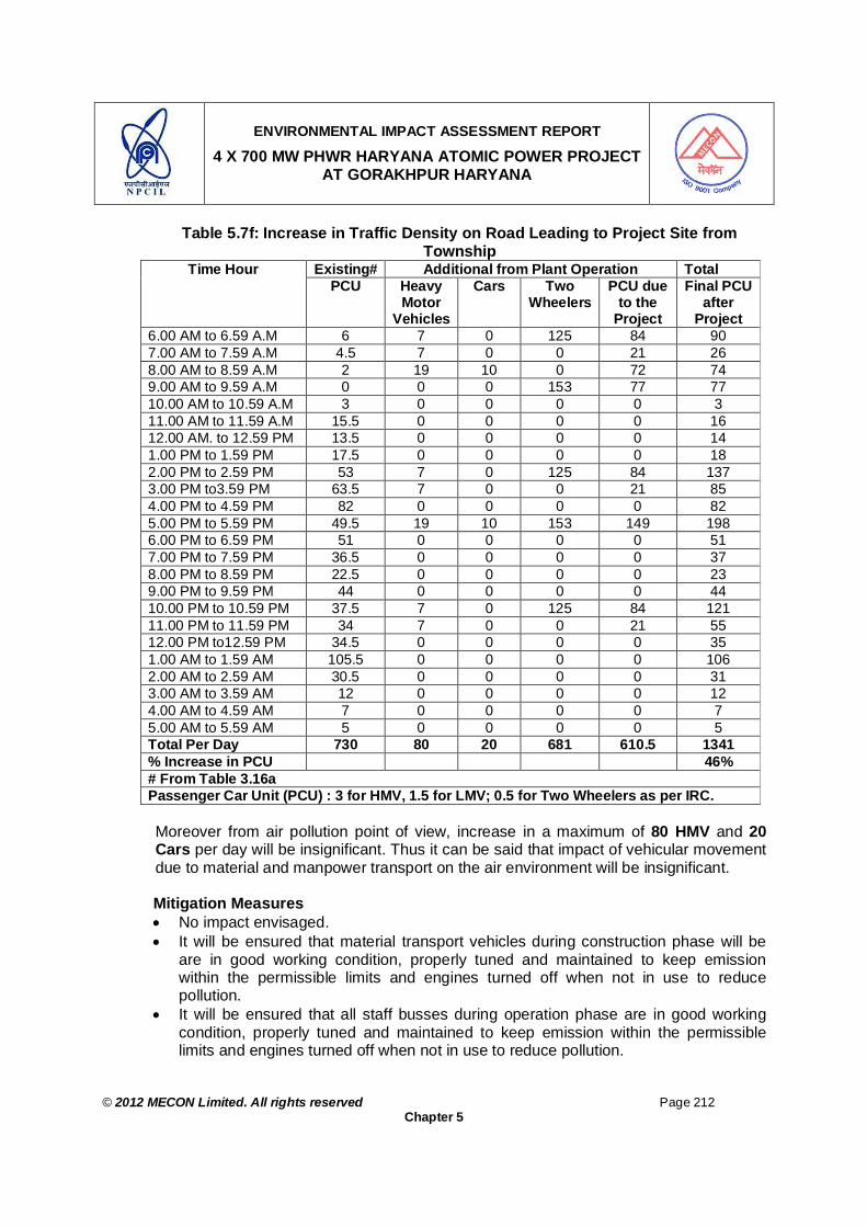
ENVIRONMENTAL IMPACT ASSESSMENT REPORT
4 X 700 MW PHWR HARYANA ATOMIC POWER PROJECT AT GORAKHPUR HARYANA
© 2012 MECON Limited. All rights reserved Page 212
Chapter 5
Table 5.7f: Increase in Traffic Density on Road Leading to Project Site from Township
Existing# Additional from Plant Operation Total Time Hour PCU Heavy
Motor Vehicles
Cars Two Wheelers
PCU due to the
Project
Final PCU after
Project 6.00 AM to 6.59 A.M 6 7 0 125 84 90 7.00 AM to 7.59 A.M 4.5 7 0 0 21 26 8.00 AM to 8.59 A.M 2 19 10 0 72 74 9.00 AM to 9.59 A.M 0 0 0 153 77 77 10.00 AM to 10.59 A.M 3 0 0 0 0 3 11.00 AM to 11.59 A.M 15.5 0 0 0 0 16 12.00 AM. to 12.59 PM 13.5 0 0 0 0 14 1.00 PM to 1.59 PM 17.5 0 0 0 0 18 2.00 PM to 2.59 PM 53 7 0 125 84 137 3.00 PM to3.59 PM 63.5 7 0 0 21 85 4.00 PM to 4.59 PM 82 0 0 0 0 82 5.00 PM to 5.59 PM 49.5 19 10 153 149 198 6.00 PM to 6.59 PM 51 0 0 0 0 51 7.00 PM to 7.59 PM 36.5 0 0 0 0 37 8.00 PM to 8.59 PM 22.5 0 0 0 0 23 9.00 PM to 9.59 PM 44 0 0 0 0 44 10.00 PM to 10.59 PM 37.5 7 0 125 84 121 11.00 PM to 11.59 PM 34 7 0 0 21 55 12.00 PM to12.59 PM 34.5 0 0 0 0 35 1.00 AM to 1.59 AM 105.5 0 0 0 0 106 2.00 AM to 2.59 AM 30.5 0 0 0 0 31 3.00 AM to 3.59 AM 12 0 0 0 0 12 4.00 AM to 4.59 AM 7 0 0 0 0 7 5.00 AM to 5.59 AM 5 0 0 0 0 5 Total Per Day 730 80 20 681 610.5 1341 % Increase in PCU 46% # From Table 3.16a Passenger Car Unit (PCU) : 3 for HMV, 1.5 for LMV; 0.5 for Two Wheelers as per IRC.
Moreover from air pollution point of view, increase in a maximum of 80 HMV and 20 Cars per day will be insignificant. Thus it can be said that impact of vehicular movement due to material and manpower transport on the air environment will be insignificant. Mitigation Measures No impact envisaged. It will be ensured that material transport vehicles during construction phase will be
are in good working condition, properly tuned and maintained to keep emission within the permissible limits and engines turned off when not in use to reduce pollution.
It will be ensured that all staff busses during operation phase are in good working condition, properly tuned and maintained to keep emission within the permissible limits and engines turned off when not in use to reduce pollution.

ENVIRONMENTAL IMPACT ASSESSMENT REPORT
4 X 700 MW PHWR HARYANA ATOMIC POWER PROJECT AT GORAKHPUR HARYANA
© 2012 MECON Limited. All rights reserved Page 213
Chapter 5
Vehicles would be regularly maintained so that emissions confirm to standards of Central Pollution Control Board (CPCB).
5.5.3.9 Impacts and Mitigation Measures for Oversized Dimensional Consignment (ODC)
During Construction Stage It can be seen from Table 5.7a, that there will be transportation of only one oversized consignment per day in the region, which may disrupt the traffic at congestion area. The oversized consignment vehicle will be directed to ply only during night between 10.00 PM to 05.00 AM, to avoid traffic congestion. Further, the existing road from NH-10 to the project site will be widened to 9 m and strengthened for transporting the ODC to the project site. The existing bridge at the canal crossing will be strengthened and any culvulets or other water body will be provided with suitable bridge system. In this regard the road from Kajalheri head works is also being evaluated for its suitability to bear the load of ODC.
5.5.4 Water and Energy Conservation Measures
Rain water harvesting measures will be implemented for the proposed project to reuse the rain water or to recharge the ground water as part of water conservation measures. Proper functioning of the systems provided will be ensured by regular monitoring. Energy conservation measures as per the design plan will be implemented so as to bring energy savings. This will include providing VVVF drives for higher capacity motors, CFL lamps etc.
5.5.5 Other Measures
The following activities will be carried out in a structured way for the benefit of the surrounding people through close co-ordination with Personnel Department: Improvement of social infrastructure through CSR activities like school buildings,
drinking water facilities, street lights, roads, sanitary facilities etc. Community education & training. Medical welfare. Sports activities.
5.5.6 Facilities for Casual Workers / Truck Drivers
The project site is rural area and fairly rich in manpower resources. The manpower resources available in the region will fulfill the demand of casual labour. Further, for labours / skilled labour coming from far off places labour colony will be established as per statutory conditions. Such labour colonies, if not properly planned, may create environmental pollution, unsanitary conditions and health problems in the area. However, it has been planned that the labour colonies with all basic facilities like, sanitation, garbage disposal, safe

ENVIRONMENTAL IMPACT ASSESSMENT REPORT
4 X 700 MW PHWR HARYANA ATOMIC POWER PROJECT AT GORAKHPUR HARYANA
© 2012 MECON Limited. All rights reserved Page 214
Chapter 5
drinking water supply, etc will be established to minimize pollution of soil, water and public health problems.
5.6 OCCUPATIONAL HEALTH AND SAFETY
During operation phase of the project, all the project activities will be carried out as per the regulations covered under Atomic Energy (Factories) Rules 1996, Electricity Act and Rules, Explosives Act and Rules, Petroleum Act and Rules etc. During commissioning, operation and maintenance of the operating units, in addition to the industrial hazards, the occupational hazard is the exposure to ionizing radiation within prescribed limits which is governed by the Atomic energy Act and Radiation Protection Rules. In order to minimize possibility of radiation exposure to the occupational workers, adequate safety measures are incorporated in the design, construction, operation and work practices of the plant including the systems associated with fuel handling and waste management. All the occupational workers undergo periodical medical check ups, bioassay sampling and whole body counting as applicable. Only qualified engineers and technicians are recruited to carry out the design, construction, operation and maintenance (O & M) of the plant. All O & M personnel undergo mandatory training (at various levels) in the plant and related subsystems of the plant through nuclear induction training. A committee consisting of a panel of experts and a representative from the regulatory agency evaluates designated operating staff for licensing. The qualification thus obtained will be renewed, periodically Mitigation Measures For ensuring better occupational health and safety the following measures will be provided: General Measures Proper control of fugitive dust from sources inside plant to keep all de-dusting
systems in prefect conditions. The de-dusting systems provided in shops will be regularly monitored and the level of dust in working zone will be reported to the management for necessary control action.
Keeping ventilation systems of premises in perfect working order to avoid accumulation of dust on equipment inside the pressurized room. Regular cleaning of air filters.
Keeping air conditioning plants in perfect running condition for control / instrumentation rooms.
Proper functioning of pollution / radiation control systems to minimise dust fall / radiation level within plant and outside areas.
Based on the environmental monitoring for radiation level, dust, gases, toxic chemical, noise & vibration, the workers exposed to these will be regularly checked in medical unit and results will be intimated to management.
ENVIRONMENTAL IMPACT ASSESSMENT REPORT
4 X 700 MW PHWR HARYANA ATOMIC POWER PROJECT AT GORAKHPUR HARYANA
© 2012 MECON Limited. All rights reserved Page 215
Chapter 5
Workers exposed to noise prone areas will be medically checked and proper noise protective equipment will be supplied to them and will be encouraged to use the same.
Spot cooling facilities will be provided for workers exposed to high heat generating areas and will be checked periodically. If necessary, rotation of duties is advised.
Proper attention is given to township water quality so that water borne disease may not affect residents.
More doctors in hospital plant medical unit will be additionally trained in the field of occupational health as policy matter.
House Keeping Measures Proper house keeping is the key to proper environmental management. This creates proper working environment for the work force and safe working conditions. However, for the proposed project the following good house keeping measures will be adopted: Regular cleaning and watering of plant roads to avoid accumulation of dust/garbage. Regular cleaning of shop floors. Avoiding accumulation and dumping of wastes and damaged equipment and items
anywhere inside the plant affecting aesthetics. Developing a positive outlook in the employees for keeping the work place, both in
factory, office or laboratory, clean and well maintained. Maintaining hygienic conditions in areas like canteens, near drinking water sources
and toilets. Personal Protective Equipments The working personnel will be given the following appropriate personal protective equipments:
Industrial Safety Helmet; Crash Helmets; Welders equipment for eye and face protection; Cylindrical type earplug; Ear muffs; Boiler suit; Safety belt / line man’s safety belt; Leather hand gloves; Acid / Alkali proof rubberized hand gloves; Canvas cum leather hand gloves with leather palm;
5.7 IMPACTS AND MITIGATION MEASURES BECAUSE OF ACCIDENTS
Impacts It can be observed that there is no hazardous chemicals are stored / handled in the project.

ENVIRONMENTAL IMPACT ASSESSMENT REPORT
4 X 700 MW PHWR HARYANA ATOMIC POWER PROJECT AT GORAKHPUR HARYANA
© 2012 MECON Limited. All rights reserved Page 216
Chapter 5
Mitigation Measures A detailed risk assessment, on-site / off-site emergency plans & Disaster Management Plan is given in Chapter 9. In addition, various fixed installations for Fire Detection, Alarm and Fire fighting will be available to effectively tackle the situation before the fire escalates into a conflagration. Regular mock drills will be conducted to check the effectiveness of the system
5.8 IMPACTS DURING DECOMMISSIONING PHASE At the end of the operating life of the operating units, which would be around 60 years for PWHR type APPs, proposed to be established at Fatehabad site, a detail decommissioning plan will be worked out. The process of decommissioning will start after the final shutdown of the plant and ends with the release of the site for a responsible organization as authorized by AERB or for unrestricted use by the public. The decommissioning plan will be prepared by NPCIL & approved by AERB and will be implemented as stated above. The plan will ensure that there will not be any radioactive releases in the public domain / environment, thus impact in the public domain due to decommissioning of the unit will be negligible. The main steps of decommissioning will be as follows:
5.8.1 General
At the end of life of a nuclear power plant, a programme of decommissioning of the retire plant is undertaken. This program which has been evolved well in advance will have provision for the following: 1. Protect public, plant personals and the environment from possible adverse effect
arising during decommissioning 2. Provide measures for protective storage and/or safe disposal of all radioactive waste
arising out of decommissioning operation. 3. Decontaminate equipment and area to acceptable levels of residual activity. 4. Ensure continued protection to public from residual radioactivity and other potential
hazards in the retired Power plant 5. Methods and procedure, including radiological protection aspect for :
- Dismantling of equipment and structure. - Collection, handling, processing, packaging, transporting and disposing
radioactive wastes. 6. Access control to radioactive areas to prevent spread of radioactive contamination
and to limit radiation doses to personnel. 7. Physical security of all contaminated and radioactive materials. 8. Surveillance and security of the retired nuclear power plant 9. Equipment, material, services and facilities including remote viewing , cutting and
handling tools and equipment required to implement the programme 10. Documentation and records.
ENVIRONMENTAL IMPACT ASSESSMENT REPORT
4 X 700 MW PHWR HARYANA ATOMIC POWER PROJECT AT GORAKHPUR HARYANA
© 2012 MECON Limited. All rights reserved Page 217
Chapter 5
5.8.2 Methods
The methods chosen for decommissioning may include any one or a combination of the following: 1. Mothballing – Putting the nuclear power plant in a state of protective storage after
removal of all fuel assemblies, radioactive fluids and wastes from site. 2. Entombment – Removal of all fuel assemblies, radioactive fluids and waste from
site and sealing all the remaining radioactive and contaminated components within a structure integral with the biological shield.
3. Dismantling – of all radioactive and contaminated materials and removal from site and decontamination of the plant area to acceptable levels for unrestricted use of the site
5.8.3 Procedure
During decommissioning, work methods and procedures will be established to demarcate areas which contain radioactive or contaminated material and regulate access to such areas.
5.8.4 Surveillance
Till such time the retired nuclear power plant area is declared fit by AERB for unrestricted use, the arrangement for surveillance and security of the plant area will include: 1. Periodic radiation survey of the plant area to verify that no radioactive material is
getting dispersed around the area. 2. Periodic environmental survey to verify that no significant relapse of radioactive
material to the environment has taken place. 3. Round the clock security to enforce access control and prevent unauthorized entry
to the plant area. 4. Inspection of physical barrier for security.
5.8.5 Documentation
A decommissioning report which includes the below mentioned aspects, is issued after all relevant operation are complete. 1. Details of decommissioning activities carried out. 2. Problems encountered and solution adopted to overcome them. 3. Final state of individual equipment and systems. 4. Type, Location, movement, quantity, and activity level of radioactive wastes. 5. Type, Quantity and activity of radioactive discharges to the environment. 6. Summary of the results of environmental survey and overall assessment of the
impact on the environment due to radioactive relapses. 7. Statistic of personnel exposures and man-ram consumption. 8. Background radiation level in the plant area after decommissioning. 9. Surveillance security arrangements for the plant area after decommissioning.

ENVIRONMENTAL IMPACT ASSESSMENT REPORT
4 X 700 MW PHWR HARYANA ATOMIC POWER PROJECT AT GORAKHPUR HARYANA
© 2012 MECON Limited. All rights reserved Page 218
Chapter 5
5.8.6 Decommissioning Cost
In arriving at the capital cost of nuclear power stations, it is normally not the practice to include decommissioning cost. In recent year all over the world, operating nuclear power station has started creating decommissioning fund. A Nominal charge is included in the unit energy cost which will accumulate with interest over the operating life of the power station for meeting the estimated cost of decommissioning of the station at the end of its useful life time. In India, the provision of decommissioning charge was introduced since 1984.
Decommissioning experience so far is limited worldwide and no large scale commercial nuclear power plant has yet been decommissioned. Based on the various studies conducted abroad and the information available in India, a cost of 1.25 Paisa / Kwh has been included as the decommissioning levy in Unit Energy Cost (UEC) for all types of power station in India. This will be updated from time to time based on evolving decommissioning experience. With effect from October 1991, the decommissioning levy is revised to 2 paisa/kwh.
5.9 MEASURES FOR MINIMIZING AND / OR OFFSETTING ADVERSE IMPACT
The potential adverse environmental impacts possible verses the mitigation measures incorporated to minimize the possible impacts, in the proposed plant have been summarized in brief in Table 5.8.
Table 5.8: Potential Impacts Verses Mitigation Measures Adopted
SN.
Impact Topics
Impact On Impact Due To Adopted Measures
Air environment
Release of air pollutants
Incorporation & installation of air pollution & radiological control systems and ensuring their effective functioning.
Water environment
Drawl of water & release of polluted waste water
Sufficiency of water availability assessed, maximum re-circulation of water envisaged, and Incorporation & installation of water pollution & radiological control systems and ensuring their effective functioning.
1 Physical Resources
Soil Release of polluted waste water, Deposition of SPM released, & Dumping of solid waste
Incorporation & installation of air, water and & radiological pollution control systems, Handling & disposal of solid waste including hazardous & radiological waste in accordance with respective statutory norms.
2 Biological Resources
Vegetation Release of polluted wastewater, Deposition of pollutants released.
The concept of defense-in-depth is adopted in design of safety systems, various state of the art safety systems mechanisms are engineered to ensure safe operation of the Atomic Power Plant.
3 Land acquisition
Land environment,
Conversion of existing land use pattern
Land being acquired by giving adequate compensation to land owners. Proper

ENVIRONMENTAL IMPACT ASSESSMENT REPORT
4 X 700 MW PHWR HARYANA ATOMIC POWER PROJECT AT GORAKHPUR HARYANA
© 2012 MECON Limited. All rights reserved Page 219
Chapter 5
SN.
Impact Topics
Impact On Impact Due To Adopted Measures
Aesthetics green belt will be erected in and around the plant premises to maintain aesthetics.
4 Noise Habitats Use of equipment having operating sound level more than the statutory level.
Noise Control measures as required have been envisaged. All noise levels will be maintained within the permissible statutory limits.
5 Hazardous Substance
Habitat, Surrounding environment
Release of hazardous chemicals
Incorporation of different process control systems, Safety features, Alarm arrangements, and follow up of Disaster management / Emergency response plan
6 Transportation
Habitat, Surrounding environment
Release of pollutant, Improper traffic management.
Use of vehicles meeting the statutory norms related to emission, proper traffic management.
7 Social & Economic
Human, livelihood, Education etc
Influx of people, Settlement, Stress on existing infrastructure etc.
No negative impact envisaged. Moreover additional social improvement activities have also been planned by the project management in the region.
8 Cultural resources
Human Influx of people, Settlement
No negative impact envisaged.
However, the detailed technological aspects of mitigation measures are given in Chapter 6.
5.9.1 Irreversible and Irretrievable Commitments of Environmental Components The project is not expected to create any irreversible and irretrievable impacts because of the following: The PAPs, whose houses (Dhanis in Haryana) are going to be acquired will be paid
due compensation as per the R&R Policy of the state. All the impacts created by the project can be mitigated by adoption of suitable
mitigation measures.
5.10 ASSESSMENT OF SIGNIFICANCE OF ENVIRONMENTAL IMPACTS 5.10.1 General
The assessment of effects of a particular action judgment must be made as to whether these effects are “Significant”. Significance is a relative concept, which reflects the degree of importance placed on the impact in question. Having identified the events associated with the proposed activity and their potential consequences, the next issue required to be addressed is the extent to which these make the proposed activity environmentally significant. In developing the criteria for determining this, the criteria outlined in the different guidelines for determining the level of environmental impact were considered.
These criteria entail an assessment of the level of certainty in the prediction of an
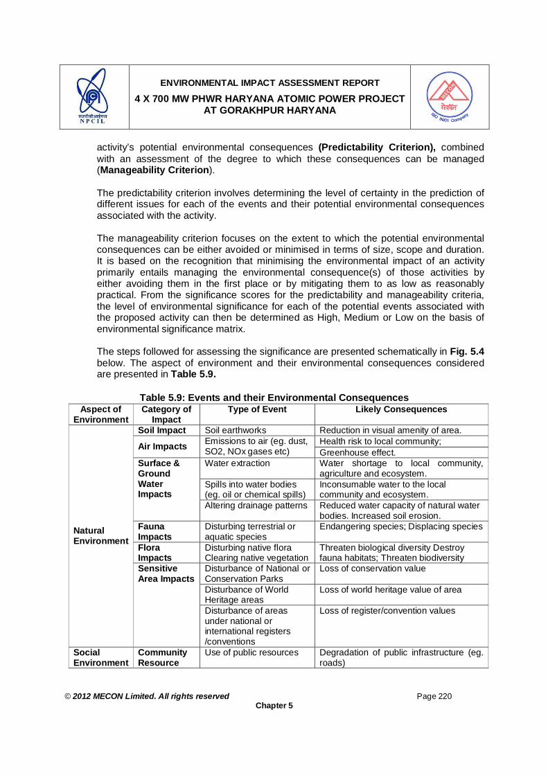
ENVIRONMENTAL IMPACT ASSESSMENT REPORT
4 X 700 MW PHWR HARYANA ATOMIC POWER PROJECT AT GORAKHPUR HARYANA
© 2012 MECON Limited. All rights reserved Page 220
Chapter 5
activity’s potential environmental consequences (Predictability Criterion), combined with an assessment of the degree to which these consequences can be managed (Manageability Criterion). The predictability criterion involves determining the level of certainty in the prediction of different issues for each of the events and their potential environmental consequences associated with the activity. The manageability criterion focuses on the extent to which the potential environmental consequences can be either avoided or minimised in terms of size, scope and duration. It is based on the recognition that minimising the environmental impact of an activity primarily entails managing the environmental consequence(s) of those activities by either avoiding them in the first place or by mitigating them to as low as reasonably practical. From the significance scores for the predictability and manageability criteria, the level of environmental significance for each of the potential events associated with the proposed activity can then be determined as High, Medium or Low on the basis of environmental significance matrix.
The steps followed for assessing the significance are presented schematically in Fig. 5.4 below. The aspect of environment and their environmental consequences considered are presented in Table 5.9.
Table 5.9: Events and their Environmental Consequences
Aspect of Environment
Category of Impact
Type of Event Likely Consequences
Soil Impact Soil earthworks Reduction in visual amenity of area. Health risk to local community; Air Impacts Emissions to air (eg. dust,
SO2, NOx gases etc) Greenhouse effect. Water extraction Water shortage to local community,
agriculture and ecosystem. Spills into water bodies (eg. oil or chemical spills)
Inconsumable water to the local community and ecosystem.
Surface & Ground Water Impacts
Altering drainage patterns Reduced water capacity of natural water bodies. Increased soil erosion.
Fauna Impacts
Disturbing terrestrial or aquatic species
Endangering species; Displacing species
Flora Impacts
Disturbing native flora Clearing native vegetation
Threaten biological diversity Destroy fauna habitats; Threaten biodiversity
Disturbance of National or Conservation Parks
Loss of conservation value
Disturbance of World Heritage areas
Loss of world heritage value of area
Natural Environment
Sensitive Area Impacts
Disturbance of areas under national or international registers /conventions
Loss of register/convention values
Social Environment
Community Resource
Use of public resources Degradation of public infrastructure (eg. roads)
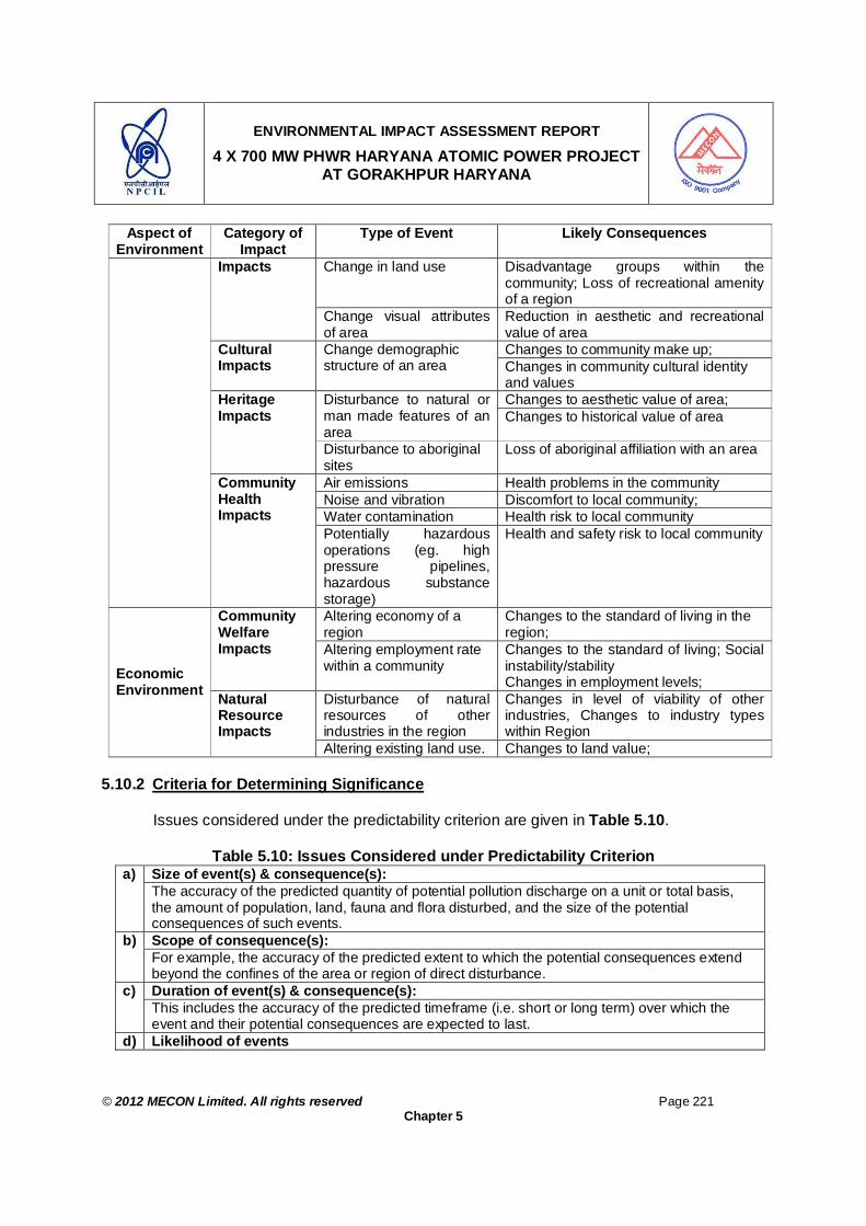
ENVIRONMENTAL IMPACT ASSESSMENT REPORT
4 X 700 MW PHWR HARYANA ATOMIC POWER PROJECT AT GORAKHPUR HARYANA
© 2012 MECON Limited. All rights reserved Page 221
Chapter 5
Aspect of Environment
Category of Impact
Type of Event Likely Consequences
Change in land use Disadvantage groups within the community; Loss of recreational amenity of a region
Impacts
Change visual attributes of area
Reduction in aesthetic and recreational value of area Changes to community make up; Cultural
Impacts Change demographic structure of an area Changes in community cultural identity
and values Changes to aesthetic value of area; Disturbance to natural or
man made features of an area
Changes to historical value of area Heritage Impacts
Disturbance to aboriginal sites
Loss of aboriginal affiliation with an area
Air emissions Health problems in the community Noise and vibration Discomfort to local community; Water contamination Health risk to local community
Community Health Impacts
Potentially hazardous operations (eg. high pressure pipelines, hazardous substance storage)
Health and safety risk to local community
Altering economy of a region
Changes to the standard of living in the region;
Community Welfare Impacts Altering employment rate
within a community Changes to the standard of living; Social instability/stability Changes in employment levels;
Disturbance of natural resources of other industries in the region
Changes in level of viability of other industries, Changes to industry types within Region
Economic Environment Natural
Resource Impacts
Altering existing land use. Changes to land value; 5.10.2 Criteria for Determining Significance
Issues considered under the predictability criterion are given in Table 5.10.
Table 5.10: Issues Considered under Predictability Criterion Size of event(s) & consequence(s): a) The accuracy of the predicted quantity of potential pollution discharge on a unit or total basis, the amount of population, land, fauna and flora disturbed, and the size of the potential consequences of such events. Scope of consequence(s): b) For example, the accuracy of the predicted extent to which the potential consequences extend beyond the confines of the area or region of direct disturbance. Duration of event(s) & consequence(s): c) This includes the accuracy of the predicted timeframe (i.e. short or long term) over which the event and their potential consequences are expected to last.
d) Likelihood of events

ENVIRONMENTAL IMPACT ASSESSMENT REPORT
4 X 700 MW PHWR HARYANA ATOMIC POWER PROJECT AT GORAKHPUR HARYANA
© 2012 MECON Limited. All rights reserved Page 222
Chapter 5
The likelihood at which the events that can potentially result in the consequences are estimated to occur. Stakeholder Concerns of event(s) & consequence(s) e) The extent to which the stakeholder perceptions, views and concerns of the events and their consequences associated with the activity is known.
As a first step, the level of certainty in the prediction of these issues has been determined and categorised as Low, Medium or High as defined in Table 5.11.
Table 5.11: Level of Certainty in the Prediction of Activity Events and their
Associated Consequences Low Extreme uncertainty in the prediction of the issue. Well-informed decision-making is very
difficult to make. Medium Some uncertainty in the prediction of the issue. Sufficient confidence in the accuracy of the
data to make informed decision-making possible. High Insignificant uncertainty in the prediction of the issue. Confidence in making an informed
decision is very high. The level of certainty for the above issues for each event is then determined. For ease of assessment, the results has been tabulated as shown below in Table 5.12

ENVIRONMENTAL IMPACT ASSESSMENT REPORT
4 X 700 MW PHWR HARYANA ATOMIC POWER PROJECT AT GORAKHPUR HARYANA
© 2012 MECON Limited. All rights reserved Page 223
Chapter 5
Identify events associated with the proposed activity and any potentially environmentally adverse consequences associated with these events
Predictability Criterion Assess the level of certainty in the prediction of the activity events and their associated adverse environmental consequences in relation to their: Size Scope, Duration, Likelihood and Stakeholder Concerns
Manageability Criterion Assess the level to which any adverse consequences for each event can be managed in relation to : Being avoided; Likelihood of occurring; Duration; Size and scope; Cumulative effects; Stakeholder concerns
Determine the environmental significance scores for each event against the predictability and manageability criterion (Table 5.11 and 5.15 respectively).
Ascertain the level of environmental significance (Low, Medium or High) for each event (environmental significance matrix : Table 5.16).
Classify level of Environmental Impact of the overall proposed activity on the basis of the level of environmental significance of each event.
Figure No. 5.4: Steps for Assessment of Significance of Environmental Impacts
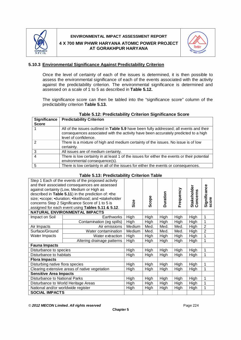
ENVIRONMENTAL IMPACT ASSESSMENT REPORT
4 X 700 MW PHWR HARYANA ATOMIC POWER PROJECT AT GORAKHPUR HARYANA
© 2012 MECON Limited. All rights reserved Page 224
Chapter 5
5.10.3 Environmental Significance Against Predictability Criterion Once the level of certainty of each of the issues is determined, it is then possible to assess the environmental significance of each of the events associated with the activity against the predictability criterion. The environmental significance is determined and assessed on a scale of 1 to 5 as described in Table 5.12. The significance score can then be tabled into the “significance score” column of the predictability criterion Table 5.13.
Table 5.12: Predictability Criterion Significance Score
Significance Score
Predictability Criterion
1 All of the issues outlined in Table 5.9 have been fully addressed; all events and their consequences associated with the activity have been accurately predicted to a high level of confidence.
2 There is a mixture of high and medium certainty of the issues. No issue is of low certainty.
3 All issues are of medium certainty. 4 There is low certainty in at least 1 of the issues for either the events or their potential
environmental consequence(s). 5 There is low certainty in all of the issues for either the events or consequences.
Table 5.13: Predictability Criterion Table
Step 1 Each of the events of the proposed activity and their associated consequences are assessed against certainty (Low, Medium or High as described in Table 5.11) in the prediction of: •the size; •scope; •duration; •likelihood; and •stakeholder concerns Step 2 Significance Score of 1 to 5 is assigned for each event using Tables 5.11 & 5.12. Si
ze
Scop
e
Dur
atio
n
Freq
uenc
y
Stak
ehol
der
Con
cern
s
Sign
ifica
nce
scor
e NATURAL ENVIRONMENTAL IMPACTS
Earthworks High High High High High 1 Impact on Soil Contamination (eg spills) High High High High High 1
Air Impacts Air emissions Medium Med. Med. Med. High 2 Water contamination Medium Med. Med. Med. High 2
Water extraction High High High High High 1 Surface/Ground Water Impacts
Altering drainage patterns High High High High High 1 Fauna Impacts Disturbance to species High High High High High 1 Disturbance to habitats High High High High High 1 Flora Impacts Disturbing native flora species High High High High High 1 Clearing extensive areas of native vegetation High High High High High 1 Sensitive Area Impacts Disturbance to National Parks High High High High High 1 Disturbance to World Heritage Areas High High High High High 1 National and/or worldwide register High High High High High 1 SOCIAL IMPACTS

ENVIRONMENTAL IMPACT ASSESSMENT REPORT
4 X 700 MW PHWR HARYANA ATOMIC POWER PROJECT AT GORAKHPUR HARYANA
© 2012 MECON Limited. All rights reserved Page 225
Chapter 5
Step 1 Each of the events of the proposed activity and their associated consequences are assessed against certainty (Low, Medium or High as described in Table 5.11) in the prediction of: •the size; •scope; •duration; •likelihood; and •stakeholder concerns Step 2 Significance Score of 1 to 5 is assigned for each event using Tables 5.11 & 5.12. Si
ze
Scop
e
Dur
atio
n
Freq
uenc
y
Stak
ehol
der
Con
cern
s
Sign
ifica
nce
scor
e
NATURAL ENVIRONMENTAL IMPACTS Community Resource Impacts Public infrastructure High High High High High 1 Land use High High High High High 1 Changes to visual attributes of area High High High High High 1 Cultural Impacts Changes to demographic structure of area High High High High High 1 Heritage Impacts Disturbance to natural features High High High High High 1 Disturbance to man made features High High High High High 1 Disturbance to aboriginal sites High High High High High 1 Community Health Impacts Air quality changes Medium Med. Med. Med. High 2 Noise and vibration High High High High High 1 Changes to water quality High High High High High 1 Hazardous operations introduced Medium Med. Med. Med. High 2 ECONOMIC IMPACTS Community Welfare Impacts Wealth and employment High High High High High 1 Natural Resource Impacts Disturbance of natural resources of other industries High High High High High 1 Altering existing land use High High High High High 1
5.10.4 Manageability Criterion
This criterion focuses on the extent to which the potential environmental consequences can be either avoided or minimised in terms of size, scope and duration. It is based on the recognition that minimising the environmental impact of an activity primarily entails managing the environmental consequence(s) of those activities by either avoiding them in the first place or by mitigating them to as low as reasonably practical. That is, any event will have an impact of some sort on the natural, social or economic aspects of the environment within which it occurs. However, the severity of the impact(s) depends on the extent to which the consequences to the environment can be eliminated or minimised. Therefore, the manageability criterion assesses the level to which the environmental consequences of each event can be either avoided or mitigated.
5.10.5 Issues Under Manageability Criterion
In assessing the level to which the environmental consequences can be managed the issues given in Table 5.14 may need to be addressed.

ENVIRONMENTAL IMPACT ASSESSMENT REPORT
4 X 700 MW PHWR HARYANA ATOMIC POWER PROJECT AT GORAKHPUR HARYANA
© 2012 MECON Limited. All rights reserved Page 226
Chapter 5
Table 5.14: Issues Considered under Manageability Criterion Avoidance of Consequences a) The extent to which the associated consequences of the various activity events can be totally avoided. Likelihood of Event Occurring The likelihood or probability of an event occurring must also be addressed. If the likelihood of such an event or sequence of events occurring has been managed so as to be very low and acceptable to other stakeholders, then it could be said that this is being managed appropriately and therefore of low significance
b)
If the likelihood of such an event or sequence of events occurring has been managed so as to be very low and acceptable to other stakeholders, then it could be said that this is being managed appropriately and therefore of low significance Duration of Consequences c) Whether the consequences can be managed to be short-term needs to be addressed – short-term needs to be defined in the context of the environment within which the potential consequences are likely to occur. That is, concepts such as the resilience of the environment would come into consideration. Size and Scope d) Consideration should be given to the extent to which the size and scope of the consequences can be managed, for example area of land, amount of flora and fauna or number of people affected by an activity. Consideration should be given to the size and intensity of the impacted environment relative to the undisturbed surroundings. Also whether the consequences are potentially catastrophic in terms of human and environmental well being, for example wide scoping and irreversible consequences. Cumulative Effects e) This includes any cumulative effects of the consequences, for example, the number of individual activities, which individually may not pose a significant environmental risk but collectively their potential consequences may be very significant in a particular region. Stakeholder Concerns f) The level of severity of the environmental consequences perceived by stakeholders (e.g. the outrage effect).
Table 5.15 outlines some basic questions, which can be used to address the above issues.
Table 5.15: Questions for Addressing Issues under Manageability Criterion Issues Questions Avoidance of consequences
Can the potential adverse environmental consequences be avoided; or are there is no such consequence? (Yes or No)
Likelihood of event
What is the probability of an event occurring, which may result in the adverse environmental consequence(s)? (Low, Medium or High on the basis of the results of the risk assessment carried out in accord with relevant standards)
Duration of consequences
Are the consequences likely to be Short, Medium or Long term?
Size and scope Can the consequences be managed so as to be small or confined to a designated area? (Small or Confined?) If they are not small or confinable are the consequences potentially catastrophic? (Wide Scoping and Irreversible).
Cumulative effects
Is it likely that the potential consequences of the proposal in conjunction with those of other existing activities are likely to pose a higher and unacceptable risk to the environment than if the individual activities where carried out on their own?

ENVIRONMENTAL IMPACT ASSESSMENT REPORT
4 X 700 MW PHWR HARYANA ATOMIC POWER PROJECT AT GORAKHPUR HARYANA
© 2012 MECON Limited. All rights reserved Page 227
Chapter 5
Issues Questions Stakeholder concerns
Is there any major concern of other stakeholders on any of the consequences of the proposed activity?
5.10.6 Environmental Significance Against Manageability Criterion
Once the potential environmental consequences have been addressed in relation to the above issues, the level of environmental significance of each of the events associated with the proposed activity can then be assessed against the manageability criterion. As with the predictability criterion, the environmental significance for the manageability criterion is assessed on a scale of 1 to 5 as described in Table 5.16.
Table 5.16: Manageability Criterion Significance score
Significance Score
Manageability Criterion
1 Adverse consequences of the various events associated with the proposed activity can be totally avoided, or it is highly unlikely that the events will ever occur.
2 Adverse consequences can be managed to be short-term. Short-term needs to be defined in the context of the environment within which the potential consequences are likely to occur.
3 Adverse consequences are not or cannot be managed to be short-term, but they can be confined so as to be insignificant in terms of size and scope relative to the surroundings.
4 Adverse consequences in conjunction with those of existing activities pose significant cumulative effects. Or Consequences are significant in terms of duration and/or size and scope relative to surroundings.
5 Consequences are potentially catastrophic. Or There is high stakeholder concern on the severity of the consequences. Catastrophic in this context means wide scope and long term or irreversible consequences such as death or serious injury to many individuals or permanent adverse change to the environment.
A step-by-step outline of the use of Tables 5.15 & 5.16 to assess the level of environmental significance for each of the events associated with the proposed activity against the manageability criterion is suggested as follows.
Step1: Where potential adverse consequences can be totally avoided; or where there are no adverse consequences associated with the events of the activity; or where there is a low likelihood of an event occurring which lead to adverse consequences being realised, then the event would be considered as being of low significance. In this case a significance score of 1 should be assigned.
Step 2: Where potentially adverse consequences cannot be totally avoided or where their likelihood of being realised is not low, consideration needs to be given to the duration of the consequences. If the consequences can be managed to occur only for short term in the context of the environment within which they will occur. In such cases a significance score of 2 should be assigned.
Step 3: If the consequences are not short term, then the question of whether or not they

ENVIRONMENTAL IMPACT ASSESSMENT REPORT
4 X 700 MW PHWR HARYANA ATOMIC POWER PROJECT AT GORAKHPUR HARYANA
© 2012 MECON Limited. All rights reserved Page 228
Chapter 5
can be confined within a designated area, which is relatively small, compared to the surrounding environment needs to be addressed. If they can be confined to being small, then a significance score of 3 is assigned. If they cannot be confined to being small and are significant in terms of size and scope relative to surroundings and/or duration, then a significance score of 4 is assigned. Step 4: Before assigning a 2 or 3 significance score, the question as to whether the consequences may pose a significant risk to the environment as a result of the cumulative effects with the consequences of other existing activities needs to be considered. If it is considered that the cumulative effects are a significant risk, a significance score of 4 should be assigned.
Step 5: In the case where the consequences are potentially catastrophic in terms of being wide scoping and irreversible, or where there are major concerns by other stakeholders of the consequences, then a significance score of 5 should be assigned. The significance score can then be entered into the “significance score” column of the manageability criterion Table 5.17.
Table 5.17: Manageability Criterion Table
Step 1 The associated consequences of each of the impacts are assessed against the following issues: •the extent to which they can be avoided; •the likelihood of events occurring which result in the impacts being realised •their duration; •the size and scope the consequences; •the cumulative effects of the consequences; and •stakeholder concerns Step 2 Each of these issues are addressed using the questions given in Table 5.15. Step 3 Significance Score of 1 to 5 is assigned for each impact-using Table 5.16.
Avo
idan
ce
Like
lihoo
d
Dur
atio
n
Size
& S
cope
Cum
ulat
ive
Effe
cts
Stak
ehol
der C
once
rns
Sign
ifica
nce
Scor
e NATURAL ENVIRONMENTAL IMPACTS Soil Impacts Earthworks No Med Short Small No No 2 Contamination (eg spills) Yes Low Short Small No Yes 2 Air Impacts Air emissions Yes Med Short Small No Yes 2 Surface/Ground Water Impacts Water extraction No - - - - - 1 Water contamination Yes Low Short Small No Yes 2 Altering drainage patterns No - - - - - 1 Fauna Impacts Disturbance to species No - - - - - 1 Disturbance to habitats No - - - - - 1 Flora Impacts Disturbing native flora species No - - - - - 1 Clearing extensive areas of native vegetation No - - - - - 1 Sensitive Area Impacts Disturbance to National Parks No - - - - - 1

ENVIRONMENTAL IMPACT ASSESSMENT REPORT
4 X 700 MW PHWR HARYANA ATOMIC POWER PROJECT AT GORAKHPUR HARYANA
© 2012 MECON Limited. All rights reserved Page 229
Chapter 5
Step 1 The associated consequences of each of the impacts are assessed against the following issues: •the extent to which they can be avoided; •the likelihood of events occurring which result in the impacts being realised •their duration; •the size and scope the consequences; •the cumulative effects of the consequences; and •stakeholder concerns Step 2 Each of these issues are addressed using the questions given in Table 5.15. Step 3 Significance Score of 1 to 5 is assigned for each impact-using Table 5.16.
Avo
idan
ce
Like
lihoo
d
Dur
atio
n
Size
& S
cope
Cum
ulat
ive
Effe
cts
Stak
ehol
der C
once
rns
Sign
ifica
nce
Scor
e
NATURAL ENVIRONMENTAL IMPACTS Disturbance to World Heritage Areas No - - - - - 1 National and/or worldwide register or convention areas
No - - - - - 1
SOCIAL IMPACTS Community Resource Impacts Public infrastructure No Med Med Small No Yes 2 Land use No - - - - - 1 Changes to visual attributes of area No - - - - - 1 Cultural Impacts Changes to demographic structure of area No - - - - - 1 Heritage Impacts Disturbance to natural features No - - - - - 1 Disturbance to man made features No - - - - - 1 Disturbance to aboriginal sites No - - - - - 1 Community Health Impacts Air quality changes No Low Med Small No Yes 2 Noise and vibration No - - - - - 1 Changes to water quality Yes Low Short Small No Yes 2 Hazardous operations introduced No Low Med Small No Yes 2 ECONOMIC IMPACTS Community Welfare Impacts Wealth and employment No - - - - - 1 Natural Resource Impacts Disturbance of natural resources of other industries No - - - - - 1 Altering existing land use No Low Med Small No No 1
5.10.7 Environmental Significance
From the significance scores for the predictability and manageability criteria, the level of environmental significance for each of the potential events associated with the proposed activity can then be determined as High, Medium or Low on the basis of environmental significance matrix presented in Table 5.18.

ENVIRONMENTAL IMPACT ASSESSMENT REPORT
4 X 700 MW PHWR HARYANA ATOMIC POWER PROJECT AT GORAKHPUR HARYANA
© 2012 MECON Limited. All rights reserved Page 230
Chapter 5
Table 5.18: Matrix for Determining Level of Environmental Significance Manageability Criterion
Scores 1 2 3 4 5 1 L L L M H 2 L L L M H 3 L M M H H 4 L M M H H
Predictability Criterion
5 L M M H H H = High; M = Medium; L = Low
As observed in Table 5.18, it is proposed that where adverse environmental consequences can be avoided or where it is very unlikely that an event will occur which would result in such consequences (i.e a Score of 1 against the manageability criterion), then the significance of the individual event associated with the proposed activity can be considered to be low regardless of the predictability score. The significance matrix provided in Table 5.19 can be developed so as to set the three levels of significance at other positions within the matrix.
Table 5.19: Activity Environmental Significance (Environmental Damage Potential) Predictability
Criterion Score 1-5
(Table 5.12)
Manageability Criterion Score 1-5
(Table 5.16)
Level of Environmental Significance H:
High M: Medium L: Low (Table 5.18)
NATURAL ENVIRONMENTAL IMPACTS
Soil Impacts Earthworks 1 2 L Contamination (eg spills) 1 2 L Air Impacts Air emissions 2 2 L Surface/Ground Water Impacts Water extraction 2 1 L Water contamination 1 2 L Altering drainage patterns 1 1 L Fauna Impacts Disturbance to species 1 1 L Disturbance to habitats 1 1 L Flora Impacts Disturbing native flora species 1 1 L Clearing extensive areas of native vegetation
1 1 L
Sensitive Area Impacts Disturbance to National Parks 1 1 L Disturbance to World Heritage Areas 1 1 L National and/or worldwide register or 1 1 L

ENVIRONMENTAL IMPACT ASSESSMENT REPORT
4 X 700 MW PHWR HARYANA ATOMIC POWER PROJECT AT GORAKHPUR HARYANA
© 2012 MECON Limited. All rights reserved Page 231
Chapter 5
Predictability Criterion Score 1-5
(Table 5.12)
Manageability Criterion Score 1-5
(Table 5.16)
Level of Environmental Significance H:
High M: Medium L: Low (Table 5.18)
convention areas SOCIAL IMPACTS Community Resource Impacts Public infrastructure 1 2 L Land use 1 1 L Changes to visual attributes of area 1 1 L Cultural Impacts Changes to demographic structure of area
1 1 L
Heritage Impacts Disturbance to natural features 1 1 L Disturbance to man made features 1 1 L Disturbance to aboriginal sites 1 1 L Community Health Impacts Air quality changes 2 2 L Noise and vibration 1 1 L Changes to water quality 1 2 L Hazardous operations introduced 2 2 L ECONOMIC IMPACTS Community Welfare Impacts Wealth and employment 1 1 L Natural Resource Impacts Disturbance of natural resources of other industries
1 1 L
Altering existing land use 1 1 L Conclusion The level of environmental significance as mentioned in Table 5.19 is the potential to damage environment. As such all the impacts of the project on various elements of environment can be predicted with significant certainty and are manageable therefore the chances of damage to environment due to the plant activities are low as shown in Table 5.19.

ENVIRONMENTAL IMPACT ASSESSMENT REPORT
4 X 700 MW PHWR HARYANA ATOMIC POWER PROJECT AT GORAKHPUR HARYANA
© 2012 MECON Limited. All rights reserved Page 232
Chapter 6
CHAPTER 6 : TECHNOLOGICAL DETAILS OF ENVIRONMENTAL PROTECTION MEASURES
6.0 TECHNOLOGICAL DETAILS OF ENVIRONMENTAL PROTECTION MEASURES 6.1 INTRODUCTION
All new or expansion projects may be accompanied by certain undesirable consequences requiring mitigative measures. Since the objective of environmental impact assessment is to ensure that development proceeds hand in hand with environmental conservation so as to achieve sustained growth, it becomes imperative that a proper mitigative vis-à-vis environmental control measures are adopted at the planning and implementation stage itself. Environmental control measures are necessary for any major projects to maintain environmental balance and to check possible harmful effects. These control measures are of multidisciplinary dimensions and varies with type of projects. Therefore, the measures described in this report are to be regarded as good beginning and depending upon the situations, continuing advice is to be updated. In this part of the report environmental management plan has been worked out based on present baseline status, and environmental impact assessment as presented in the environmental impact assessment part of the report. It has already been indicated earlier in the EIA part that a number of environmental factors needs to be considered covering ambient air quality, water pollution, solid waste management, social factors, etc. The technological environmental control measures envisaged for the proposed project are described in following text. Anticipated releases of hazardous substances like radioactive materials and fissile materials to the environment and its impact have been discussed in previous chapters. Reducing/ regulating releases to the stipulated levels and/or mitigation of consequences of releases that occur call for incorporation of several engineered features and for the adoption of appropriate work practices, too. This chapter deals with these aspects. Conventional waste management is also dealt with in this chapter. As in the previous chapter, the measures are discussed separately for each phase of project activity.
6.2 CONSTRUCTION PHASE
The site is at Gorakhpur Village, Fatehabad, Haryana, which is a green-field site. During construction phase, the environmental pollution is not expected to be significant and would be of short duration. The project site is agricultural land and due compensation will be paid to the land owners for the same. The site is at Gorakhpur Village, Fatehabad, Haryana, which is a green-field site. During site clearing, site-stripping activity will be carried out during non-monsoon season to avoid any discharge of soil or silt to nearby surface water bodies. Topsoil excavated will be stored separately for later use.

ENVIRONMENTAL IMPACT ASSESSMENT REPORT
4 X 700 MW PHWR HARYANA ATOMIC POWER PROJECT AT GORAKHPUR HARYANA
© 2012 MECON Limited. All rights reserved Page 233
Chapter 6
During excavation steps would be taken to prevent cave-in, landslide, water accumulation, runoff due to rain, loose excavated material falling or rolling. Further, refilling, disposal and transport of soil, dust suppression by water spraying will be practiced to avoid generation of fugitive dust. A system of work permit procedure will be followed for excavation, concrete handling activities and all erection activities especially involving heights. These will be inspected regularly. Rigging operations, platforms, scaffoldings staircases, ladders and ramps, working at heights, welding and cutting, hand tools and power tools would be inspected periodically. Lifting machineries, tools and tackles would be certified before use. During site clearing as well as construction, movement of earth moving machineries, concrete mixing and pouring systems and lifting machineries would be regulated. Every effort would be taken to minimize disturbance to the existing trees.
6.3 OPERATIONAL PHASE
The basic design of the Atomic Power Plant allows for planned / controlled release of radioactive or chemical pollutants to the environment within statutory limits. There could be accidents and off normal situations that may have a potential for large uncontrolled releases. APP employs a twofold approach in design to deal with such situations. The first approach aims to avert such situations to the best extent possible. This is done by monitoring and rigorously controlling the plant operating conditions. Moreover, design features such as process and equipment selection also play a role in this context. The second approach aims at designing the facility in such a way that even if the event were to occur, the resulting unplanned releases are contained as far as practical. Provisions are made for directing the releases along planned flow paths, thereby permitting their collection and treatment before discharge to the environment. This is facilitated by handling / processing radioactive material in confined space, the confinement being assured by providing multiple barriers between the environment and the radiation sources. The multiple barrier approach is applied not only in processing, but also in storage of hazardous materials / wastes. The sections that follow discuss the use of multiple barriers as mitigative measures under normal plant operation. Apart from the steps taken to avert / contain unplanned releases, the design provides for the reduction of pollution burden by minimizing the quantum of wastes generated in normal operation. These are also illustrated in the sequel.
6.3.1 Mitigation by Facility Design – Containment and Contamination Control The Reactor Building (RB) is of double containment where the inner one is known as Primary Containment (PC steel lined) and the outer one are Secondary Containment (SC). The PC is further classified into two volumes namely high enthalpy areas and low enthalpy areas. High enthalpy areas comprise of areas which contain high enthalpy fluids and are potential source of heavy water (D2O) leakage. These areas are normally

ENVIRONMENTAL IMPACT ASSESSMENT REPORT
4 X 700 MW PHWR HARYANA ATOMIC POWER PROJECT AT GORAKHPUR HARYANA
© 2012 MECON Limited. All rights reserved Page 234
Chapter 6
not accessible. The SG room, Pump Room (PR) and Fuelling Machine (FM) vaults areas fall under this category. Rest of the areas fall under the category of low enthalpy areas and are normally accessible except moderator room, Fuel Transfer (FT) rooms, Delayed Neutron Monitoring (DNM) and FM service areas (FMSA) during communication with FM vault. Double containment philosophy has been followed in RB. The containment system consists of an inner (primary) containment enveloped by an outer (secondary) containment. The Primary Containment is provided with Carbon Steel (CS) liner to reduce leak rate. The annulus between the inner and outer containments is kept at a slightly negative pressure with respect to the atmosphere so as to minimize ground level activity releases to the environment during an accident condition.
The purpose of containment building during normal operation is to: Provide an envelope around the structure housing / supporting Calandria, end
shields, reactivity mechanisms, PHT and moderator systems, fuelling systems and various associated systems.
Provide shielding, as also to permit access to equipment within the containment building under reactor operating / shutdown conditions.
Provide shielding, as also to permit access to equipment within the containment building under reactor operating / shutdown conditions.
To keep the release of radioactivity during normal operation within prescribed limits. To control the spread of radioactive contamination, the plant is divided into three distinct radiation zones, classified according to their potential for radioactive contamination and / or radiation exposure.
The Zoning Philosophy is Implemented as Follows : A single point entry is provided. This is in the Zone-1 area of the nuclear building. Personnel and material movement from higher to lower zone and vice-versa
permitted in sequence only. Barriers and radiation monitors are provided at inter-zonal boundaries for effective
control of spread of contamination.
Decontamination Facilities : For personnel decontamination, showers have been provided in Zone 2. A special decontamination room near the main airlock of each unit is provided for
highly contaminated personnel. Equipment decontamination facility is provided at 100m elevation in Waste
Management Plant (Zone-3).
6.3.2 Mitigation by Facility Design – Ventilation System Ventilation system acts as a dynamic barrier to keep the air borne activity in the operating areas of the plant under control and to keep the discharges to the atmosphere within permissible limits.

ENVIRONMENTAL IMPACT ASSESSMENT REPORT
4 X 700 MW PHWR HARYANA ATOMIC POWER PROJECT AT GORAKHPUR HARYANA
© 2012 MECON Limited. All rights reserved Page 235
Chapter 6
The areas in the plant are divided into three zones1 based on the based on increasing contamination potential. Ventilation system is designed to maintain pressure differential between various confinement zones and also between the confinement zone and the outside atmosphere so that the direction of the flow of air or gases is from the areas with lower contamination potential to the areas with higher contamination potential. For ventilation to be an effective barrier, the confinement of air borne radioactive particulates, noxious fumes and vapors need to take place as close to the point of origin as practicable. This is achieved by isolating the ventilation of operating areas, access galleries etc from that of off gas streams from RB, auxiliary airlock, spent fuel storage/inspection bay and decontamination centre & resin fixation area in waste management building, etc. Other salient features of the ventilation system that go to make it effective are outlined below.
6.3.2.1 Primary Containment Ventilation System The Reactor Building (RB) is of double containment [(Primary Containment (PC steel lined)] and the outer one are Secondary Containment (SC)] as given under Section 6.3.2.2. The PC is further classified into two volumes namely high enthalpy areas (high radioactivity contamination) and low enthalpy areas (low radioactivity contamination). For the purpose of contamination control and ventilation requirements, separate high enthalpy and low enthalpy areas are maintained.
The Primary Containment ventilation system is designed for the following requirements. To supply cooled, filtered and dehumidified fresh air and exhaust stale air to meet
the fresh air requirement of O&M personnel during normal and Shutdown period. Ensure flow of air from low active zones to high active zones thus preventing the
spread of activity inside RB.
1 Zone 1: No radioactive equipments are there in this zone and is kept free of contamination at all
times. All floors of Control Building, Station Auxiliary Buildings, Safety Related and Fire Water Pump Houses, Turbine Building, EMWP, DOSA, IDCTs and buildings under safety class – NINS are in Zone-1. Zone 2: This zone includes the service area for active equipment and material that have potential for contamination and is likely to be contaminated at times. Instrument and control maintenance shop, chemical control lab., FM testing area, FM maintenance area, shipping flask loading area, shipping flask wash down area, bay equipment, electrical workshop, Reactor Auxiliary System, bio-assay, counting room, source room, shift health physics room, emergency showers & toilets in Nuclear Building, heavy water up-grading plant, exhaust ventilation area, new fuel storage and waste management plant facilities excluding decontamination and resin fixation areas and FM and mechanical workshop are in Zone 2. Zone 3: This zone contains source of contamination. Contamination in this area is kept localised and under control by routine cleanup operation, however, some parts are likely to remain contaminated. The area/room which are grouped in this zone are RB, auxiliary airlock, spent fuel storage/inspection bay and decontamination centre & resin fixation area in waste management building.

ENVIRONMENTAL IMPACT ASSESSMENT REPORT
4 X 700 MW PHWR HARYANA ATOMIC POWER PROJECT AT GORAKHPUR HARYANA
© 2012 MECON Limited. All rights reserved Page 236
Chapter 6
Maintaining the PC under negative pressure with respect to SC and ambient to prevent leakage of air from PC during normal operation.
The desired area temperatures inside PC are maintained by the APW fed air-cooling units (ACUs) in high enthalpy areas and chilled water-cooled air handling units (AHUs) in low enthalpy areas.
Ventilation flow has been decided in such a way as to meet the ventilation requirements, while limiting heavy water vapor loss & tritium release (through exhaust) at a minimum. Provision is made to monitor the activity release through stack. In order to ensure negative pressure in PC with respect to SC and outside atmosphere, only exhaust fans are provided in the ventilation system.
Provision is made to isolate moderator room and FM service areas from PC ventilation system and connect them to Heavy Water Vapour Recovery (HWVR) system by providing air operated dampers in supply and exhaust ventilation lines and also in branch lines connecting these areas to dryer. The exhaust from FT room is passed through a Combined HEPA and Charcoal filter to take care of lodine release, if any. To reduce the dust ingress into the PC, filers with minimum 90% efficiency down to 10 microns are provided at the intake. The exhaust to the stack is through pre filters (designed for 99% efficiency down to 5 microns) and HEPA (designed for minimum 99.97% efficiency down to 0.3 microns) filters.
6.3.2.2 Secondary Containment Ventilation System
SC surrounds PC from raft to dome with a gap of about two meters. The objective of the SC ventilation is to prevent the SC atmosphere from becoming stale and to provide fresh air for occasional occupancy. SC ventilation system is designed on the following basis :
SC does not have any continuous occupancy as it does not house any equipment and also there is no major heat load other than that from lighting. Consequently continuous ventilation for SC is not required. However to prevent the atmosphere from becoming stale, ventilation system with exhaust air flow is provided. Under normal operating condition of the reactor, PC is negative with respect to SC and hence leakage flow can take place from SC to PC and not vice versa. Hence activity will not spread from PC to SC. Provision is made to isolate SC under RB isolation logic, with provision of two isolation dampers on both supply and exhaust line.
6.3.2.3 Reactor Building Heavy Water Vapour Recovery System
The system is provided to recover heavy water vapor arising out of chronic leakages / spills from primary heat transport, moderator and fuelling machine circuit in the Reactor Building (RB) Primary Containment (PC) atmosphere. Recovery is made by adsorption of the vapor on molecular sieves and then regeneration of the bed and condensing the water. Condensate from the dryer equipment is collected by condensate collection system.
Heavy water vapor recovery system maintains the fuelling machine vaults and pump room (high enthalpy) areas under negative pressure with respect to low enthalpy accessible areas thus preventing activity spread from these areas to accessible areas.

ENVIRONMENTAL IMPACT ASSESSMENT REPORT
4 X 700 MW PHWR HARYANA ATOMIC POWER PROJECT AT GORAKHPUR HARYANA
© 2012 MECON Limited. All rights reserved Page 237
Chapter 6
Heavy water vapor recovery system also helps in reducing the tritium activity levels in pump room, fuelling machine vaults, fuelling machine service areas, moderator room, delayed neutron monitoring room, fuel transfer room, fuelling machine valve station, etc. High enthalpy area contains all high enthalpy heavy systems and includes pump room (PR), fuelling machine vaults (FMVs) and fuelling machine service areas (FMSAs) when connected with FMV. These areas are generally accessible only during shutdown period of the reactor. Low enthalpy areas like PHT equipment room, feed pump equipment room, moderator room, delayed neutron monitoring room, fuel transfer rooms, north and south galleries, staircase, FMSAs (when the area is not connected with FMV) are normally accessible during reactor operation with a few exceptions. Some areas like moderator room, delayed neutron (DN) monitoring rooms, fuel transfer (FT) rooms are not accessible during normal operation. Different areas in PC are connected to heavy water vapor recovery system, in which heavy water vapors are recovered as downgraded heavy water condensate. Typically each dryer consists of adsorption & regeneration circuits, ducting and condensate collection system piping. Purge dryer is provided to maintain slight negative pressure in FMV & Pump room with respect to accessible areas.
6.3.2.4 RAB Air Conditioning and Ventilation System
Air Conditioning (A/C) & Ventilation system provided for Reactor Auxiliary Building (RAB) is designed with an objective to ensure adequate supply of fresh & filtered air for the operating personnel, remove heat load generated in the operating areas due to equipment and / or human occupancy and maintaining air flow from lower contaminated areas to higher contaminated areas to minimize spread of contamination. RAB consists of the portion of Nuclear Building (NB).excluding Reactor Building (RB). This building houses Spent Fuel Storage Bay (SFSB), equipment of moderator and PHT purification systems, workshops & maintenance areas, change rooms, Backup Control Room (BCR), Heavy water vapor recovery systems, supply unit of RAB ventilation system including air washer, cable passage area, etc. Nuclear building is divided into zone 3 or 2 or 1 based on contamination levels and potential for activity release. Ventilation design for these buildings is based on activity considerations, zoning and desired area temperature requirements. For the purpose of design, the various areas may be categorized as follows :
1. Areas where occasional fission product activity release, particularly of I-131 is likely –
spent fuel storage bay (SFSB) and Tray Loading Bay (TLB) areas, spent fuel flask decontamination area.
2. Areas where high tritium release is likely – PHT purification area, evaporation clean up, de-deuteration facility etc.
3. Areas where occasional beta-gamma and tritium release are likely – chemical laboratories, mechanical maintenance shops, and decontamination areas.

ENVIRONMENTAL IMPACT ASSESSMENT REPORT
4 X 700 MW PHWR HARYANA ATOMIC POWER PROJECT AT GORAKHPUR HARYANA
© 2012 MECON Limited. All rights reserved Page 238
Chapter 6
4. Other areas where radiation levels are low. Exhaust from areas under category (1) requires to be filtered for iodine removal. The number of air changes in all these areas is based both on activity considerations, heat load and the local air coolers provided for the area.
Fresh air supply system caters to the fresh air requirements of the above areas and Secondary Containment (SC) of Reactor Building (RB. Exhaust system is common for RAB-1 and RAB-2, Waste Management Plant (WMP), Mechanical and FM workshops.
6.3.2.5 Emergency Fresh Air Ventilation for MCR
The Main Control Room at 111 M Elevation of control building is provided with fresh air during emergency condition when outside air becomes contaminated due to accidental release of radioactivity during postulated LOCA involving fuel failure. The system consists of louvers, pre-filters, combined HEPA & charcoal filters, centrifugal fans, dampers, ducting, grills, etc. During normal condition Emergency Fresh Air Ventilation system remains boxed up and non-operational, and fresh air requirements for AHUs of Control Room is met by the normal make up route. In case of radioactivity in the outside air, normal fresh air make up route is closed and makeup supply to the aforesaid room is provided by Emergency Fresh Air Ventilation route.
Outside air is sucked by a centrifugal fan through louvers, pre-filters and combined HEPA & Charcoal filters and is supplied to the MCR. The pre-filter removes dust particles and combined HEPA & charcoal filters reduces the radioactivity from the air before it is supplied to MCR.
6.3.2.6 Treatment and Discharge of Gaseous Effluent Stream
The gaseous radioactive effluents from reactor and service building ventilation exhaust systems are passed through pre filters and absolute filters before discharge through the stack. These gaseous effluents are continuously monitored for radioactivity content before discharging through stack. There are three gross β(Beta), γ(Gamma) activity monitors on each of the reactor building (RB) ventilation exhaust ducts (located in Service Building). These are connected to the Reactor Building containment isolation system logics for isolation (boxing up) of Reactor Building containment, in the event of two out of three β, γ activity monitors detect the activity level, on the Reactor Building exhaust duct, more than the pre-set values. Simultaneously, the sample of active air discharged is collected in the sample bottle of the air sample collection system for later analysis in the laboratory. The radioactivity in the gaseous effluents, routinely released through stack, are monitored by the following monitoring/ sampling systems Inert gas (gross-gamma) monitors: These monitors consist of scintillation detector
assembly mounted inside aluminum chambers with inlet/outlet connections. Iodine-in-air monitors: These monitors consist of NaI Scintillation detector
assembly and electronics processing unit. Particulate activity monitors: These monitors consist of plastic scintillator
assembly facing particulate filter paper and associated electronics.

ENVIRONMENTAL IMPACT ASSESSMENT REPORT
4 X 700 MW PHWR HARYANA ATOMIC POWER PROJECT AT GORAKHPUR HARYANA
© 2012 MECON Limited. All rights reserved Page 239
Chapter 6
Tritium-in-air monitors: Bubbler sample collection system / Gamma compensated ionization chambers.
All these stack-monitoring instruments are located in a room known as the Stack Monitoring Room, which is located, near the stack. This location provides low radiation background. Iso-kinetic probe draws the air sample, which successively passes through the filter detector assemblies of the air particulate and iodine activity monitors. Subsequently, it is led to the inert gas monitor chamber and then routed back to the stack. The data from the above monitors are analyzed by a signal-processing unit, which gives release rate and integral releases over a set period. These are also compared with set levels and alarms are generated if the activity exceeds the set levels. Permissible Gaseous Discharge Limits The radiation dose limit for the general pubic at the fence post due to operation of all facilities within the site through all pathways is 1 mSv/y (100 mrem/y). The annual average rate of discharge of gaseous radioactive effluents from all the units of 700 MW(e) shall not exceed the following limits. Corresponding dose to the public at 1.0 Km boundary is also given.
Dose at Exclusion Boundary (mSv/y)
Gaseous Radio-active Effluents Stack Release 4X700 MWe unit
GBq/d Adult Infant Tritium 2.02E+04 1.61E-02 1.61E-02 C-14 1.08E+01 9.28E-03 9.28E-03 Fission Product Noble Gases (FPNGs) 1.10E+04 3.04E-02 4.56E-02 Ar-41 7.66E+03 3.72E-02 5.58E-02 I-131 2.02E-01 4.70E-03 5.74E-02 Particulates 2.02E-01 4.12E-02 8.00E-02
Total 1.39E-01 2.64E-01
Radioactive gaseous effluents when averaged over one day, shall not exceed ten times the annual average release rates specified above.
6.3.2.7 Ventilation System Availability Continued availability of the ventilation system is essential. This is accomplished by providing adequate standby equipment. Standby fans and filters of 100 % capacity are available under all process operating conditions. Emergency power is supplied automatically to fans in the event of failure of the normal power supply. The ventilation system is designed robustly so that it is available continuously even if one of its components (equipment or control device) fails. For instance, when any fan is inoperative, standby fans automatically start to maintain system airflow. Back flow through the inoperative fan is prevented by automatically isolating it by the dampers provided. The continued availability of the ventilation system is further assured by periodic surveillance to test its operability and required functional performance. The tests include (i) measurement of air flow in main systems, area pressures in the different zones,

ENVIRONMENTAL IMPACT ASSESSMENT REPORT
4 X 700 MW PHWR HARYANA ATOMIC POWER PROJECT AT GORAKHPUR HARYANA
© 2012 MECON Limited. All rights reserved Page 240
Chapter 6
differential pressure in Cells and Glove boxes, face velocity in front of fume hoods, pressure drop across filter banks, (ii) checking the working of the normal operating sequence that would bring ventilation systems into action and (iii) checking the transfer to alternative power sources when regular power is interrupted. The materials of construction for the ventilation systems are carefully selected to withstand corrosion particularly when associated with chemical processes, offer fire resistance, ensure long operating life to avoid frequent replacement of contaminated equipment and enable smooth surface finish to aid in decontamination.
6.3.3 Mitigation by Facility Design : Radioactive Waste Storage / Disposal
6.3.3.1 General The waste management design philosophy is based on the principle of ALARA (As low As Reasonably Achievable). The underlying philosophy for radioactive waste management is based on three major approaches, namely, a. Dilute and Disperse: This approach is employed for the discharge of potentially
active liquid wastes (dilution is by water addition) and treated gaseous wastes (dilution is by ventilation air). In this case, harm that can be caused by radio-nuclides is brought down to an acceptable or insignificant level.
b. Delay, Decay and Disperse: All short-lived radio-nuclides are rendered harmless by
storing them for some time and allowing them to decay. The cooling of spent fuel inside the reactor for 8 months may be cited as examples of this.
c. Concentrate and Contain: Nearly 99.9% of radio-nuclides with medium and long
half-lives are concentrated to reduce the waste volume, immobilized, sealed in containers and then stored away inside engineered structures. The storage period is sufficiently long for the radio-nuclides to decay.
Since bulk of the waste is going to be concentrated and contained, the third approach needs to be looked at a little more closely. So long as the integrity of the isolation of radio-nuclides is preserved, no harm to the environment or living organisms is expected. Therefore, engineered measures aim to make the chance of failure of isolation very, very low. This is done by making use of multiple barriers each of which has low failure probability. Even if a failure of multiple barriers were to occur, the geological setting selected for eventual disposal ensures that migration of radio-nuclides are retarded so much that sufficient delay and decay would occur. Though complete prevention of radioactive waste generation is a difficult task, keeping the waste generation to the minimum practicable is an essential objective of radioactive waste management. In doing so, it is essential to minimize waste generation in all the stages of a nuclear power plant. Waste minimization refers to waste generation by operational and maintenance activities of plant and secondary waste resulting from predisposal management of radioactive waste. Nuclear effluents are being given the

ENVIRONMENTAL IMPACT ASSESSMENT REPORT
4 X 700 MW PHWR HARYANA ATOMIC POWER PROJECT AT GORAKHPUR HARYANA
© 2012 MECON Limited. All rights reserved Page 241
Chapter 6
prime attention right from generation, handling, treatment, conditioning, transportation, storage and final disposal, in a manner that it meets the requirements of the Safety Guide – AERB/SG/D – 13 Liquid and Solid Radioactive Waste Management in PHWRs and the discharge limits specified by them. A Waste Management Plant (WMP) is provided for segregation, collection, treatment, conditioning, storage, monitoring and safe disposal of liquid and solid radioactive wastes generated in the plant. Following systems are provided at waste management plant : a. Liquid effluent segregation system (LESS) b. Storage, treatment and disposal system – for low level activity and high volume liquid
waste. c. Evaporation system (after ion-exchange process) – for evaporating the relatively high
active and low volume tritium bearing liquid waste followed by dispersal through air route / stack.
d. Spent Ion Exchange (IX) resin management system e. Volume reduction facility f. Decontamination system g. Laundry system.
6.3.3.2 Radioactive Liquid Waste Management System
The liquid waste streams generated from the plant are segregated at source and are collected in collection storage tanks located in Liquid Effluent Segregation System (LESS) area. Liquid Effluent Segregation System (LESS) LESS design philosophy is to ensure segregation and collection at source of all the liquid wastes generated in the station based on level of activity and chemical nature, so as to i. Minimize cross contamination and ii. Facilitate judicious decision for management of each category of waste. The classifications and the category they belong to and the origin of the wastes are given in Table 6.1a.
Table 6.1a: Classification of Liquid Wastes SN. Classification Category Sources 1. Potentially Active
Waste (PAW) I, II Showers from Nuclear building and upgrading plant, wash
room and laundry waste 2. Active Non-chemical
Waste (ANCW) I, II Equipment and floor drains from Nuclear building, drains
from decontamination centre and other areas of WMP and vent exhaust room. Laboratory rinses and washes.
3. Active Chemical Waste (ACW)
I, II, III Laboratory solutions from nuclear building and decontamination centre drains.
4. Tritiated Waste (TTW) I, II D2O upgrading reject, moderator room sump in RB, drains from heavy water handling areas in Nuclear building.
5. Organic Waste (OW) I Liquid scintillation counters, contaminated oil, grease, etc.

ENVIRONMENTAL IMPACT ASSESSMENT REPORT
4 X 700 MW PHWR HARYANA ATOMIC POWER PROJECT AT GORAKHPUR HARYANA
© 2012 MECON Limited. All rights reserved Page 242
Chapter 6
Waste Categorization Categorization of liquid waste streams based on radioactivity concentration (as approved by AERB) is as follows :
Category – I : Gross beta gamma activity less than 1 x 10⁻⁶ µCi/ml (0.037 MBq/m³). This category waste does not normally require treatment. However filtration followed by dilution and monitoring is provided for the category.
Category – II: Gross beta gamma activity between 1 x 10⁻⁶ to 1 x 10⁻³ µCi/ml
(0.037 to 37 MBq/m³). This category of waste may require treatment. Filtration or filtration and ion exchange treatment followed by dilution is provided for this category. However tritium bearing liquid effluent will normally be evaporated, diluted with large volume of exhaust air and discharged through 100 meter high stack.
Category – III: Gross beta activity between 1 x 10⁻³ to 1 x 10⁻¹ µCi/ml (37 to 3700
MBq/m³). This category waste requires treatment. Equipment shielding may be necessary. Generation of this category is occasional.
Category – IV: Gross beta activity between 1 x 10⁻¹ to 1 x 10⁴ µCi/ml (3700 to 3.7
x 108 MBq/m³). This category of waste requires treatment. Equipment shielding is also necessary. Waste of this category is also not encountered in PHWRs.
Category – V: Gross beta activity more than 1 x 10⁴ µCi/ml (3.7 x 10⁸ (MBq/m³).
This category waste is heat generating waste. Shielding, treatment and cooling is required for such wastes. However waste of this category is not encountered in PHWRs.
The quantity of liquid waste in each classification and the treatment methods are given in Table 6.1b.
Table 6.1b: Estimated Volumes of Liquid Waste Generation at HAPP – 1 & 2 Activity levels
(Bq/ml) Activity inventory Waste stream Quantity
m³/day Gross
β-γ Tritium Gross
β-γ (KBq) Tritium (MBq)
Treatment
1.0 Potentially Active Waste (PAW) Showers 30 3.7E-3 250 111 7500 Washings 20 3.7E-2 250 740 5000 Laundry 25 3.7E-1 100 10360 2500
Filtration, dilution with plant water drainage system and discharged to Bhakra canal.
2.0 Active Non-Chemical Waste (ANCW)
12 1.85 1850 22200 2220 Filtration, polishing through IX column, evaporation, dilution with exhausts air and

ENVIRONMENTAL IMPACT ASSESSMENT REPORT
4 X 700 MW PHWR HARYANA ATOMIC POWER PROJECT AT GORAKHPUR HARYANA
© 2012 MECON Limited. All rights reserved Page 243
Chapter 6
Activity levels (Bq/ml)
Activity inventory Waste stream Quantity m³/day
Gross β-γ
Tritium Gross β-γ (KBq)
Tritium (MBq)
Treatment
discharged through stack.
3.0 Tritiated Waste (TTW) Moderator room sump
2 1.85 11E4 3700 222000
D2O upgrading plant
6 0.371 7.4E4 2220 444000 - Do -
4.0 Active Chemical Waste (ACW)
1 1850 18500 Occasional Occasional Neutralized & treated like ANCW.
5.0 Organic waste
13.7 litre / day
0.037 1850 Occasional Occasional
Total 96.01 39331 683220 Storage Treatment and Disposal System
Storage Adequate capacity for liquid waste storage is provided through 12 nos. of large diameter hold up tanks at RCC dyke area of Waste Management Plant (WMP). Total storage capacity in the dyke provided is 3200 m³ to take care of unusual conditions when discharge of liquid waste is not possible due to canal closure and also the storage required for off-normal waste like Steam Generator (SG) tube leak, contaminated APW etc. and in line with the requirements of AERB guide AERB/SG/D-13. Liquid waste of all categories can be stored for about one month period. Treatment and Disposal through Water Route All the twelve number steel tanks are located in a RCC containment (top open) called dyke area. This is water tight structure and seismically qualified to SSE level of earthquake.
Two nos. of receipt tanks for each stream have been provided at RCC dyke area in which one will be receiving the liquid waste and the liquid from other tanks will be under processing. Two nos. of micron filters (1 working and 1 standby) are provided for each stream. The segregated liquid effluents, to decide the mode of discharge, are divided into two categories viz. i) low level high volume waste (PAW and LW) and ii) tritium bearing waste (ANCW, TTW and neutralized ACW). After filtration, the low level high volume liquid wastes (waste water from shower, washroom and laundry area) are stored in the post treatment tank. Low level treated liquid waste from post treatment tank is sampled, analyzed in the laboratory and monitored after preparing a batch of treated waste. This treated waste is then injected into the plant water discharge (Blow down) piping. Inline mixers are

ENVIRONMENTAL IMPACT ASSESSMENT REPORT
4 X 700 MW PHWR HARYANA ATOMIC POWER PROJECT AT GORAKHPUR HARYANA
© 2012 MECON Limited. All rights reserved Page 244
Chapter 6
provided in the pipe line to ensure thorough mixing of treated waste with plant water discharge system, before it gets discharged.
Liquid waste discharges are made in batches normally on single shift basis. Availability of blow down flow is ensured through control logics and administrative control before commencing of discharge of treated waste. The activity concentration of liquid waste being discharged is monitored by an online activity monitor located on treated waste line in WMP (before injecting it in plant water discharge system) in addition to sampling and analysis carried out in laboratory. On attaining set level of activity the activity monitor fitted in the discharge line will trip the discharge pump.
Liquid wastes having relatively high tritium and Beta gamma activity like Tritiated Waste (TTW) generated from Upgrading plant rejects, Moderator room sump & Clean-up system and Active Non Chemical Waste (ANCW) generated from Equipment decontamination system of WMP, chemical laboratory & SFSB cask wash down area, of less volume will be evaporated, diluted with exhaust air and discharged through stack to air route. This quantum of liquid waste activity constitutes a major portion of the total activity in the liquid waste. Therefore only less than 10% of total activity contained in major volume of liquid effluent activity from HAPP – 1&2 will be added to the liquid route discharge point.
Treatment and Disposal Liquid Waste through Air Route (Evaporation System) Liquid effluent having relativity higher activity are treated by filtration and ion exchange process and disposed through air route using Evaporation system. Streams like ANCW, ACW and TTW, after filtration, will be diverted to a synthetic ion exchange column to remove the dissolved Beta-gamma activity and then stored in evaporation system feed tank. These polished tritium bearing liquid waste streams (free of gross beta activity) are sent to a steam heated evaporator with a controlled flow rate of 1.4 m³/hr. This vaporized stream is then injected into the ventilation exhaust ducting leading to 100 m high stack. Evaporation of effluents having relatively higher level of activity ensures the discharges through water route are kept at minimum. The air route mode of disposal offers unique advantage of higher release limits per unit of dose allocation as compared to liquid route. This mode of disposal suits inland site where water body is scarce and extensively used by the surrounding population. The liquid waste disposal scheme is shown in Fig. 6.1.
Liquid Discharge Limits For the plant, at the common discharge point the following discharge limits are considered.
Dose at Exclusion Boundary (mSv/y) Radionuclide Stack Release 4X700 MWe unit GBq/d Adult Infant
Tritium 2.02E+03 4.04E-02 4.80E-02 C-14 1.08E-01 6.96E-05 5.60E-05 Cs-137 1.00E-01 1.44E-03 7.76E-04 Sr-90 1.00E-01 3.10E-03 8.50E-03 Total 4.50E-02 5.72E-02
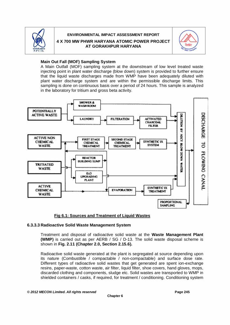
ENVIRONMENTAL IMPACT ASSESSMENT REPORT
4 X 700 MW PHWR HARYANA ATOMIC POWER PROJECT AT GORAKHPUR HARYANA
© 2012 MECON Limited. All rights reserved Page 245
Chapter 6
Main Out Fall (MOF) Sampling System A Main Outfall (MOF) sampling system at the downstream of low level treated waste injecting point in plant water discharge (blow down) system is provided to further ensure that the liquid waste discharges made from WMP have been adequately diluted with plant water discharge system and are within the permissible discharge limits. This sampling is done on continuous basis over a period of 24 hours. This sample is analyzed in the laboratory for tritium and gross beta activity.
Fig 6.1: Sources and Treatment of Liquid Wastes
6.3.3.3 Radioactive Solid Waste Management System
Treatment and disposal of radioactive solid waste at the Waste Management Plant (WMP) is carried out as per AERB / SG / D-13. The solid waste disposal scheme is shown in Fig. 2.11 (Chapter 2.0, Section 2.15.6).
Radioactive solid waste generated at the plant is segregated at source depending upon its nature (Combustible / compactable / non-compactable) and surface dose rate. Different types of radioactive solid wastes that get generated are spent ion-exchange resins, paper-waste, cotton waste, air filter, liquid filter, shoe covers, hand gloves, mops, discarded clothing and components, sludge etc. Solid wastes are transported to WMP in shielded containers / casks, if required, for treatment / conditioning. Conditioning system

ENVIRONMENTAL IMPACT ASSESSMENT REPORT
4 X 700 MW PHWR HARYANA ATOMIC POWER PROJECT AT GORAKHPUR HARYANA
© 2012 MECON Limited. All rights reserved Page 246
Chapter 6
for solid waste provided in WMP include processes like spent resin management for resins from Primary Heat Transport (PHT) System, Moderator system, end shield cooling system, calandria vault cooling system, SFSB cooling and purification system, cementation of liquid filters / sludge and compaction of compressible wastes. The waste after treatment / conditioning is disposed off in engineered barriers. There are different types of structures depending on the radiation level encountered, like stone lined earth trenches, RCC vaults / trenches and tile holes / high integrity containers (HIC) located at the Near Surface Disposal Facility (NSDF), depending upon their surface dose rate. The structures serve as engineered barriers preventing migration of radioactivity into ground water, and together with the surrounding soil provide the required radiation shielding. Some of the wastes may have to be stored temporarily in specially designed facilities. Solid Waste Categorisation Solid waste is categorised on the basis of its surface radiation dose-rate and its physical characteristics which call for specific treatment and handling processes. These are : Cat. I : Waste with surface dose rate up to 2 mSv/h. For the purpose of segregation of source, Cat. I waste is further divided into two groups viz. a. Dose rate less than 0.02 mSv/hr – Disposed off in stone lined earthen trenches. b. Dose rate more than 0.02 mSv/hr and less than 2 mSv/h – Disposed off in RCC
trenches / Vaults. Depending upon the physical nature, these wastes are also classified as : a. Compactable waste and b. Non – compactable waste. c. Combustible waste Cat. II : Waste with surface dose rate more than 2 mSv/h but less than 0.02 Sv/h. Cat. III : Waste with surface dose rate more than 0.02 Sv/h. The category of waste is further sub-divided into two groups viz. a. Cat. III A : Waste packages with surface dose – rate up to 0.5 Sv/h, and b. Cat. III B : Waste packages having surface dose-rate more than 0.5 Sv/h. Resin Transfer and Fixation System Radioactive Spent Ion-Exchange resin is generated from Primary Heat Transport, Moderator, End shield / calandria vault cooling and Spent Fuel Storage and Inspection Bay (SFSB) clean-up systems in PWHR type reactors. These resins vary widely in dose rate, radio nuclide content and their concentrations. Disposal of Resins with Short Lived Radioactivity Spent resins are transferred from the Ion Exchange vessel (Stainless Steel Hopper) of moderator, End Shield / Calandria vault cooling system, into a Carbon Steel Hopper, dewatered by compressed air and these CS Hoppers are disposed (after closure of all

ENVIRONMENTAL IMPACT ASSESSMENT REPORT
4 X 700 MW PHWR HARYANA ATOMIC POWER PROJECT AT GORAKHPUR HARYANA
© 2012 MECON Limited. All rights reserved Page 247
Chapter 6
nozzle openings) in engineered barriers provided at Near Surface Disposal Facility (NSDF).
Disposal of Resins with Long Lived Radioactivity PHT / SFSB spent resins contain fission product radio-nuclides having long half life of about 30 years. These resins are required to be fixed in a monolithic block so as to prevent the release of radio-nuclides to environment. Conditioning of spent ion exchange resin in polymer / cement matrix is aimed at immobilising the resin in monolithic blocks and arresting release of radioactive nuclides to the environment. The resins are in the form of beads which are easily dispersed if not contained in a suitable matrix.
At WMP, Resin Transfer system and resin fixation system is provided at Ground floor (EL – 100.000 M) and is provided with all around shielding wall. All the equipment and piping, handing active resins, are provided with adequate shielding to have ease of operation and maintenance and also to reduce the back ground radiation level. The system material is of stainless steel for ease of decontamination.
Decontamination system (DC) An equipment Decontamination Centre is provided at WMP building for decontamination of removable and reusable small equipment, components, pipes, heavy water drums etc. having a maximum size of 600 mm dia. and 3500 mm length. This system provides surface decontamination of various parts using ultrasonic cleaning and steam.
Decontamination Centre (DC) is designed to decontaminate items having surface dose rate up to 0.01 Sv/hr. However, components having surface dose rate more than 0.01 Sv/hr and up to 0.1 Sv/hr, can be decontaminated using this system in Ultrasonic tank – I (UT-I) which is provided with a hematite shielded enclosure. In addition, special operating procedure will be made for handling such components having higher surface dose rate. Such components having surface dose rate more than 0.01 Sv/hr may come once in a while and not on a regular basis.
Laundry System An active laundry is provided to decontaminate clothing and rubber wears such as lab coats, hand gloves, Shoe cover, coveralls etc received from the station. The laundry equipment are provided to take care of the entire washing load of contaminated protective wears from HAPP – 1&2 on a single shift operation basis. However, increased load requirements, if any, during shutdown and other contingencies can be met by increasing the number of shifts. This system is located in reactor auxiliary building at EI 100.000 M very close to change room (point of generation) and new cloth issue room (point of utilization) thereby avoiding movement of contaminated clothing from change room to laundry system. The drain lines from these laundry machines are led to laundry waste collection sump from where it is filtered and pumped to laundry waste collection tank of dyke area. Incineration of Low Level Combustible Solid Waste An oil fired incinerator is provided to incinerate organic liquid waste and low level (less than 2mR/hr) combustible solid waste (other than plastic waste). The off-gas is cleaned

ENVIRONMENTAL IMPACT ASSESSMENT REPORT
4 X 700 MW PHWR HARYANA ATOMIC POWER PROJECT AT GORAKHPUR HARYANA
© 2012 MECON Limited. All rights reserved Page 248
Chapter 6
by two stage water scrubbers before discharging it through 30m tall chimney. Continuous monitoring system is provided to monitor the gas emitted from the chimney. Solid Waste Disposal Solid wastes after conditioning will be disposed off in the Near Surface Disposal Facility (NSDF) area in earth trenches / RCC trenches / vaults / tile holes / HIC depending upon their surface dose rate. As a matter of practice packages having higher activity are disposed off at the bottom of trenches / vaults will be suitably sealed permanently as per established practices. These data will be utilised to assess the safety aspects of the waste repository. Necessary geo-hydrological & soil analysis studies for the NSDF site will be carried out to assess the safety of NSDF containing solid waste generated from 50 years of plant operation. Proper surveillance of Solid Waste Management Facility is carried out through bore holes provided all around the NSDF to check the integrity of the engineered barriers through periodic water sampling. Additional array of boreholes will be provided, whenever the facility is augmented. The NSDF area is fenced and necessary access control procedures are established. A waste assaying is carried out to assess and record the radioactive content in each conditioned waste packages before disposing them. Name of the vault and their identification also recorded.
The dose rate on the top of the sealed earth trenches and RCC trenches / vaults would not exceed 0.01 mGy/h. Near Surface Disposal Facility (NSDF) The engineered measures for solid waste disposal are graded in accordance with the level of radioactivity activity encountered. An overview of these is presented below. Stone Lined Earthen Trenches: The Suspected or low level solid wastes (surface dose less than 0.02 mSv/h, Cat-I) after being immobilized in cement matrix are buried in stone lined earthen trenches. These are shallow excavation in soil of size 5 m x 2.5 m x 2 m deep. Filled trenches are covered by brick and overlain by soil. Reinforced cement concrete (RCC) trenches: are used for disposal of part of Cat-I and Cat-II waste (up to 0.5 Sv/h). These trenches have water-proof tiles at the bottom and on lateral surfaces, and the top is closed with RCC covers. Typically, these are constructed in a battery with four rows of sizes 1.2 m (depth) x 1.8 m (width) x 20 m (length). The trenches are usually built zone by zone, each of which would be sufficient for 3 – 5 years of operation. Fig. 6.3 shows a schematic of the RCC trench. The site selected for NSDF is such that the ground water table is below the planned storage depth, the soil has high enough cation exchange capability (CEC) to retain or slow down the migration of radio-nuclides in the event of their leakage, and surface water sources are at least 100 m away. Moreover, back fill materials with large CEC could also be used all around the RCC trench / tile hole zones to enhance retention. Bore holes are provided around NSDF to monitor activity leaking into ground water. The net volume of solid waste generated (after due processing) per year that would be disposed off in NSDF is around 514m3/yr.

ENVIRONMENTAL IMPACT ASSESSMENT REPORT
4 X 700 MW PHWR HARYANA ATOMIC POWER PROJECT AT GORAKHPUR HARYANA
© 2012 MECON Limited. All rights reserved Page 249
Chapter 6
Size & Life of Radioactive Solid waste Disposal Facility Adequate Land required for Near Surface Disposal Facility (NSDF) will be allotted during detailed plant layout stage. This requirement will include 50-60 years of operating life, once in life time En-massse Coolant Channel Replacement (EMCCR) requirement and decommissioning requirements. Initially the disposal modules of NSDF such as Earth Trenches, RCC Trenches and Tile holes will be made to meet the requirement of approximately 10 years of reactor operation and will be augmented as and when required.
NSDF is designed for 50-60 years of operating life followed by 30 years of instructional control period.
Size of Disposal Modules 1. Earth Trenches : 4m x 4 m x 2 m deep (10 trenches will be constructed initially). 2. RCC Trenches : 32 trenched in one modules. Two modules will be constructed
Initially Size of Trench : 5.885 m x 1.475 m x 3 m deep each.
Fig. 6.2 Schematic Section Diagram of RCC Trench

ENVIRONMENTAL IMPACT ASSESSMENT REPORT
4 X 700 MW PHWR HARYANA ATOMIC POWER PROJECT AT GORAKHPUR HARYANA
© 2012 MECON Limited. All rights reserved Page 250
Chapter 6
Fig. 6.3: Schematic Section Diagram of the Tile Hole Incinerator The main objective of the incinerator is to minimize the activity disposal in earthen trenches thereby reducing the activity ingress into ground water. This is one of the most widely used method for volume reduction of low level combustible waste by which reduction in disposal space and cost reduction in engineered barriers can be achieved. This system will cater to very low level active combustible solid waste like paper-waste, cotton waste, mops, discarded clothing, packing materials etc. The incinerator will only after collecting required volume of waste to optimize the fuel requirement to start the incinerator. Generally 2 to 3 days of operation per month is sufficient. Chimney height will be 30m and the exit gas will pass through two stage water scrubber. Plastic waste will be fused (melt densification method) in a drum to achieve significant volume reduction. About 114kg/yr of combustible waste will be generated. This will be disposed of by means of a package Incinerator of 50 kg per hour capacity.
The incinerator proposed is of rotary kiln type. It comprises of a cylindrical mild steel chamber (Primary chamber), stationary secondary chamber and flue gas treatment systems. The heating is provided with primary and secondary burners. Hopper and ram loaders that operate automatically are provided to feed the waste into the incinerator.

ENVIRONMENTAL IMPACT ASSESSMENT REPORT
4 X 700 MW PHWR HARYANA ATOMIC POWER PROJECT AT GORAKHPUR HARYANA
© 2012 MECON Limited. All rights reserved Page 251
Chapter 6
The primary chamber is designed to withstand extremely high temperature and is refractory lined and insulated accordingly. It is provided with a variable speed drive to achieve the desired speed of rotation depending upon the waste being incinerated. It has slight inclination to allow the refuse to move continuously. As the primary chamber keeps rotating, there is no need of raking of waste. The incinerator design is such that the flue gas and the waste travel in opposite direction, ensuring maximum efficiency of combustion. The ash in the primary chamber falls to the bottom and automatically gets collected into ash container. The flue gases are transferred from the rotary drum in to the secondary chamber where there is sufficient residence time for flue gases. Thereafter the flue gases pass through the gas cleaning system to the stack. The process flow diagram is shown in the Fig. 6.4. .
Fig. 6.4: Process Flow Diagram for Package Rotary Kiln Incinerator
6.3.3.4 Spent Fuel Storage and Management Spent Fuel Spent fuel is removed from the reactor core and transferred to spent fuel inspection bay (SFIB) where it is inspected for leaks / pin holes / damage. It is then stored in spent fuel storage bay (SFSB) which is under continuous radiological surveillance. The spent fuel is stored in SFSB till it cools down to dry storage level (about 5 years). Subsequent action on the spent fuel is dictated by the policy of the Department of Atomic Energy / Government of India.
Feed to incinerator
Main combustion
chamber (primary rotating
chamber)
Post combustion
chamber (secondary stationery chamber)
Heat recovery system (heat
exchanger /spray dryer)
Sterile ash
Gas cleaning system
(bag filter, Scrubber)
Stack

ENVIRONMENTAL IMPACT ASSESSMENT REPORT
4 X 700 MW PHWR HARYANA ATOMIC POWER PROJECT AT GORAKHPUR HARYANA
© 2012 MECON Limited. All rights reserved Page 252
Chapter 6
Size of Spent Fuel Storage Bay The size of one SFSB can accommodate 10 years of spent fuel discharge and one core load. Design / Technology The spent fuel storage and management system’s design will be such that the radiation dose to the members of public from all the routes is restricted to 1000 µSv/y. At present no reprocessing facility is envisaged for HAPP Site. The establishment and management of reprocessing facility of spent fuel falls within the purview of DAE and the same will be addressed suitably. Moreover, the requirement of reprocessing of the spent fuel will arise only after 12 years from now, as the reactor will be under construction for 5 - 6 years followed by another 5 -10 years for the cooling of spent fuel. The technology to be adopted at that time is difficult to propose at the movement, as technology undergoes continuous improvements and up-gradation. However, the latest and safest technology available at that time will be applied.
6.3.4 Conventional Waste Management 6.3.4.1 Sewage Treatment Plant at HAPP
A conventional sewage treatment plant is planned as a common facility for HAPP. This would be located in the northwest corner of the site adjacent to the Fatehabad branch of Bhakra canal. The rated capacity of the plant is 0.5 Million Liters Per day (MLD).
The treated effluent will meet the following characteristics. pH – 6.5 to 8.5, TSS < 30 mg/l, BOD <20 mg/l.
6.3.4.2 Sewage Treatment Plant at Township
Refer Section 2.28.1, Chapter 2.
6.3.4.3 Solid Waste Disposal at HAPP HAPP would generate non-radioactive solid waste from zone 1 which is exclusively office waste, comprising mostly of waste papers and biodegradable waste from canteen. The canteen biodegradable waste after being segregated at source will be sent for composting by vermin-culture within the plant premises. The paper waste coming out will be sold to local vendors for recycling.
6.3.4.4 Solid Waste Disposal at Township
Refer Section 2.28.2, Chapter 2. 6.4 GREEN BELT DEVELOPMENT: MITIGATION MEASURES 6.4.1 General
Green belt, is an important sink for air pollutants, it also absorbs noise. Enhancing green cover not only mitigates pollutants but also improves the ecological conditions / aesthetics and reduces the adversities of extreme weather conditions. Trees also have

ENVIRONMENTAL IMPACT ASSESSMENT REPORT
4 X 700 MW PHWR HARYANA ATOMIC POWER PROJECT AT GORAKHPUR HARYANA
© 2012 MECON Limited. All rights reserved Page 253
Chapter 6
major long-term impacts on soil quality and the ground water table. By using suitable plant species, green belts can be developed in strategic zones to provide protection from emitted pollutants and noise. Plant species suitable for green belts should not only be able to flourish in the area but must also have rapid growth rate, evergreen habit, large crown volume and small / pendulous leaves with smooth surfaces. All these traits are difficult to get in a single species. Therefore a combination of these is sought while selecting trees for green belt. The green belt should be planted close to the source or to the area to be protected to optimize the attenuation within physical limitations. The green belt / cover will serve the following purposes:
Compensate the damage to vegetation due to setting up and operation of the proposed plant.
Prevent the spread of fugitive dust generated due to project and allied activities. Attenuate noise generated by the project. Reduce soil erosion Help stabilise the slope of project site. Increases green cover and improve aesthetics. Attract animals to re-colonise the area.
6.4.2 Selection of Species
The species for plantation have been selected on the basis of soil quality, place of plantation, chances of survival, commercial value (timber value, ornamental value, etc.), etc. It is to be noted that only indigenous species will be planted. Exotic species like Eucalyptus and Australian acacia will not be planted. The species for green belt / vegetation cover development will be selected in consultation with State Forest Department and State Soil Conservation Department. Mixed plantations will be done keeping optimum spacing between the saplings. However, the species suitable for planting in the area as recommended by Central Pollution Control Board in their publication “Guidelines for Developing Greenbelts” (PROBES/75/1999-2000) are given under various heads here under.
6.4.3 Plantation Scheme
Plant saplings will be planted in pits at about 2.0 m to 3.0 intervals so that the tree density is about 1500 trees per ha. The pits will be filled with a mixture of good quality soil and organic manure (cow dung, agricultural waste, kitchen waste) and insecticide. The saplings / trees will be watered using the effluent from the sewage treatment plant and treated discharges from project. They will be manured using sludge from the sewage treatment plant. In addition kitchen waste from plant canteen can be used as manure either after composting or by directly burying the manure at the base of the plants. Since, tests have shown that availability of phosphorus, a limiting nutrient, is low, phosphoric fertilisers will also be added. The saplings will be planted just after the

ENVIRONMENTAL IMPACT ASSESSMENT REPORT
4 X 700 MW PHWR HARYANA ATOMIC POWER PROJECT AT GORAKHPUR HARYANA
© 2012 MECON Limited. All rights reserved Page 254
Chapter 6
commencement of the monsoons to ensure maximum survival. The species selected for plantation will be locally growing varieties with fast growth rate and ability to flourish even in poor quality soils. A total of more than 33% of total project area will be developed as green belt or green areas in project area and other areas including the residential complex. The widths of the belt will be >20m along the project boundary, depending on the availability of space. The proposed Green belt / cover development is shown in Drg. No. HAPP-1 to 4/70000/2002/GA (DR.LWS).Rev.01 A very elaborate green belt development plan has been drawn for the proposed plant. The areas, which need special attention regarding green belt development in the project area, are:
1. Around plant units 2. Plant Boundary 3. Vacant Areas in Plant 4. Around Office Buildings, Garage, Stores etc. 5. Along Road Sides (Avenue Plantation) 6. Plantation in Township
Annual winds in the study area are mainly from W, NW, SW and N. Inside the HAPP works area, the region with high fugitive pollution load are areas around road, parking areas and go-downs where loading and unloading of different materials takes place. To arrest the fugitive emissions emitted from above areas tree plantation will be undertaken in general all around the HAPP but the more in strategic places especially on E, SE, NE and S of the above areas along with that in other directions. To arrest the fugitive emissions emitted from such areas, the approach adopted shall be - as described below and as shown in Fig. 6.5: Plantation all around close to the units / areas (fugitive emission source) in available
spaces to arrest fugitive emissions at the source. Considering the HAPP as centre and planting trees in a “V” in SW-SE; SE-NE; NE-
NW direction [i.e down wind (D/W) of predominant winds, E, SE, NE and S] at staggered distances in available spaces to arrest fugitive emissions which have not been arrested by the green belt at the source.
Plantation along the plant boundary - >20m depending on space availability.

ENVIRONMENTAL IMPACT ASSESSMENT REPORT
4 X 700 MW PHWR HARYANA ATOMIC POWER PROJECT AT GORAKHPUR HARYANA
© 2012 MECON Limited. All rights reserved Page 255
Chapter 6
Fig. 6.5: Schematic Diagram of Greenbelt Development
1. Around Plant Units
As there will be limited space (in height) due to various over head pipelines, thus small and medium sized species are suggested and they should be planted depending on the vertical height and lateral space available for the plant growth. The above-mentioned areas / direction should be covered with pollution tolerant species (in the space available around) as mentioned below:
Scientific Name Common Name Acacia jacquemontii Babool Acacia nilotica Kikar Acacia senegal Khairi Bougainvillea spp. Bougainvellea Carissa spinarum Hins Duranta sp. Duranta Murraya exotica Kamayani Nerium sp Pink Kaner Prosopis cineraria Jand Thevieta peruviana Yellow Kaneer
2. Along Plant Boundary
Green belt is to be developed along the project boundary of the atomic power complex and the residential complex plant boundary. The proposed plantation should be in three concentric orbits:
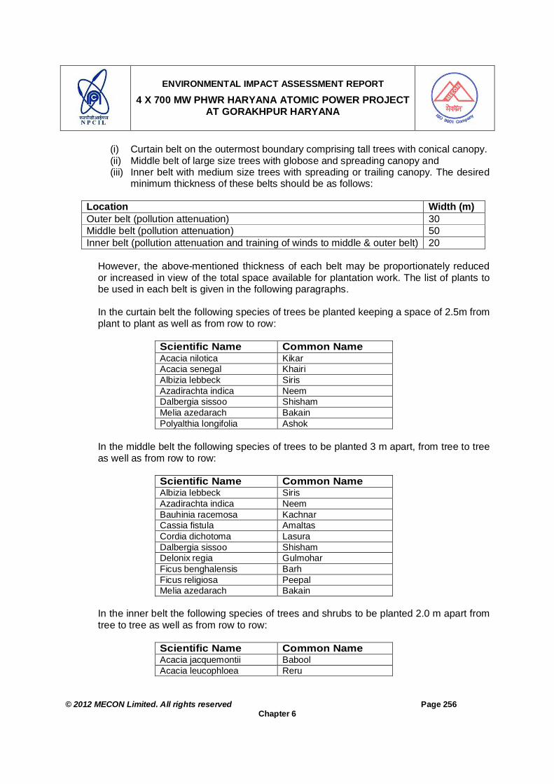
ENVIRONMENTAL IMPACT ASSESSMENT REPORT
4 X 700 MW PHWR HARYANA ATOMIC POWER PROJECT AT GORAKHPUR HARYANA
© 2012 MECON Limited. All rights reserved Page 256
Chapter 6
(i) Curtain belt on the outermost boundary comprising tall trees with conical canopy. (ii) Middle belt of large size trees with globose and spreading canopy and (iii) Inner belt with medium size trees with spreading or trailing canopy. The desired
minimum thickness of these belts should be as follows:
Location Width (m) Outer belt (pollution attenuation) 30 Middle belt (pollution attenuation) 50 Inner belt (pollution attenuation and training of winds to middle & outer belt) 20
However, the above-mentioned thickness of each belt may be proportionately reduced
or increased in view of the total space available for plantation work. The list of plants to be used in each belt is given in the following paragraphs.
In the curtain belt the following species of trees be planted keeping a space of 2.5m from
plant to plant as well as from row to row:
Scientific Name Common Name Acacia nilotica Kikar Acacia senegal Khairi Albizia lebbeck Siris Azadirachta indica Neem Dalbergia sissoo Shisham Melia azedarach Bakain Polyalthia longifolia Ashok
In the middle belt the following species of trees to be planted 3 m apart, from tree to tree
as well as from row to row:
Scientific Name Common Name Albizia lebbeck Siris Azadirachta indica Neem Bauhinia racemosa Kachnar Cassia fistula Amaltas Cordia dichotoma Lasura Dalbergia sissoo Shisham Delonix regia Gulmohar Ficus benghalensis Barh Ficus religiosa Peepal Melia azedarach Bakain
In the inner belt the following species of trees and shrubs to be planted 2.0 m apart from
tree to tree as well as from row to row:
Scientific Name Common Name Acacia jacquemontii Babool Acacia leucophloea Reru

ENVIRONMENTAL IMPACT ASSESSMENT REPORT
4 X 700 MW PHWR HARYANA ATOMIC POWER PROJECT AT GORAKHPUR HARYANA
© 2012 MECON Limited. All rights reserved Page 257
Chapter 6
Scientific Name Common Name Acacia nilotica Kikar Acacia senegal Khairi Capparis decidua Karir Carissa spinarum Hins Prosopis cineraria Jand
3. Vacant Areas in Atomic Power Plant and Residential Complex Plantation in vacant areas will be selected from among the following species. Plantation will be done in staggered trench manner 3.0 apart.
Scientific Name Common Name Albizia lebbeck Siris Azadirachta indica Neem Bauhinia racemosa Kachnar Cassia fistula Amaltas Cordia dichotoma Lasura Dalbergia sissoo Shisham Delonix regia Gulmohar Ficus benghalensis Barh Ficus religiosa Peepal Melia azedarach Bakain
4. Plantation around Office Buildings, Stores, Garage etc of the Atomic Power Complex and the Residential Complex The species recommended for plantation around various buildings will include:
Scientific Name Common Name Albizia lebbeck Siris Azadirachta indica Neem Bauhinia racemosa Kachnar Cassia fistula Amaltas Cordia dichotoma Lasura Dalbergia sissoo Shisham Delonix regia Gulmohar Ficus benghalensis Barh Melia azedarach Bakain Polyalthia longifolia Ashok
5. Avenue Plantation of the Atomic Power Complex and the Residential Complex Double rows of avenue trees on the outer side of the footpaths are recommended; an
outer row of shade trees and an inner row of ornamental flowering trees will be planted.
(a) Foliage Trees for Outer Avenue:
Scientific Name Common Name Acacia leucophloea Reru Albizia lebbeck Siris

ENVIRONMENTAL IMPACT ASSESSMENT REPORT
4 X 700 MW PHWR HARYANA ATOMIC POWER PROJECT AT GORAKHPUR HARYANA
© 2012 MECON Limited. All rights reserved Page 258
Chapter 6
Scientific Name Common Name Azadirachta indica Neem Cordia dichotoma Lasura Dalbergia sissoo Shisham Ficus benghalensis Barh Ficus religiosa Peepal Melia azedarach Bakain
(b) Flowering / Ornamental Trees for Inner Avenue:
Scientific Name Common Name Bauhinia racemosa Kachnar Bougainvillea spp. Bougainvellea Cassia fistula Amaltas Cassia javanica Java-ki-rani Delonix regia Gulmohar Lagerstroemia parviflora Lagerstroemia Nerium sp Pink Kaner Polyalthia longifolia Ashok Thevieta peruviana Yellow Kaneer
6. Plantation in Township In the 75 ha township there will be about 1700 dwelling units. The areas along the roads and in vacant spaces will be available for plantation. The species for avenue plantation will be same as given under Clause 5 above. The design of green belt and the species all along the township boundary will be from among that given under Clause 2 above. The species for vacant spaces and office buildings like, clubs, guest house, etc in the township will be from among the species as mentioned respectively under Clauses 3 & 4 under Section 6.4.3.
6.4.4 Post Plantation Care Immediately after planting the seedlings, watering will be done. The wastewater discharges from different sewage treatment plant / out falls will be used for watering the plants during non-monsoon period. Further watering will depend on the rainfall. In the dry seasons watering will be regularly done especially during February to June. Watering of younger saplings will be more frequent. Manuring will be done using organic manure (animal dung, agricultural waste, kitchen waste etc.). Younger saplings will be surrounded with tree guards. Diseased and dead plants will be uprooted and destroyed and replaced by fresh saplings. Growth / health and survival rate of saplings will be regularly monitored and remedial actions will be undertaken as required.
. 6.4.5 Phase Wise Green Belt / Cover Development Plan
Green belt will be developed in a phase wise manner right from the construction phase of the proposed project. In the first phase along with the start of the construction activity the plant boundary, around the proposed waste dumps, and the major roads will be

ENVIRONMENTAL IMPACT ASSESSMENT REPORT
4 X 700 MW PHWR HARYANA ATOMIC POWER PROJECT AT GORAKHPUR HARYANA
© 2012 MECON Limited. All rights reserved Page 259
Chapter 6
planted. In the second phase the office building area will be planted. In the third phase when all the construction activity is complete plantation will be taken up in the plant area, around different units, in stretch of open land and along other roads.
6.5 CONCLUSION From the foregoing description it is evident that mitigative measures form integral part of the design of the Atomic Power Plant. The present plans to mitigate the environmental impact from radiation and conventional pollutants seem to be adequate and no additional measurers are likely to contribute effectively. References [1] "Manual on Security of Nuclear Power Plants". AERB
[2] "The Physical Protection of Nuclear Material", INFCIRC /225/Rev.1, IAEA Circular

ENVIRONMENTAL IMPACT ASSESSMENT REPORT
4 X 700 MW PHWR HARYANA ATOMIC POWER PROJECT AT GORAKHPUR, HARYANA
© 2012 MECON Limited. All rights reserved Page 260
Chapter 7
CHAPTER 7 : ENVIRONMENTAL MONITORING PROGRAMME (EMP)
7.0 ENVIRONMENTAL MONITORING PROGRAMME (EMP) 7.1 INTRODUCTION
The monitoring and evaluation of the mitigation measures envisaged are critical activities in implementation of the Project. Monitoring involves periodic checking to ascertain whether activities are going according to the plans. It provides the necessary feedback for project management to keep the program on schedule. The purpose of the environmental monitoring plan is to ensure that the envisaged purpose of the project is achieved and results in desired benefits. To ensure the effective implementation of the proposed mitigation measures, the broad objectives of monitoring plan are:
To evaluate the performance of mitigation measures proposed in the EMP. To evaluate the adequacy of Environmental Impact Assessment To suggest improvements in management plan, if required To enhance environmental quality. To implement and manage the mitigative measures defined in EMP. To undertake compliance monitoring of the proposed project operation and
evaluation of mitigative measure. 7.2 IMPLEMENTATION ARRANGEMENT The various components of the environment needs to be monitored on regular basis
during construction and operation phase of the project, as per the requirements of regulating agencies as well as for trend monitoring of the pollutants levels in various environmental matrices.
7.2.1 During Construction Stage During construction stage different issues / components involved in environmental
monitoring programme will be looked upon by Planning Section and Environmental Survey Laboratory (ESL) and the two will report to Project Director (PD) for review. The monitoring of conventional pollutant will be taken up by hiring local agencies / consultants. Whereas, the radiological parameters will be monitored by ESL.
7.2.2 During Operation Stage
At the project, an Environmental Management Apex Review Committee (EMARC) will
be formed, which will review the effectiveness of environmental management plan of the project during construction phase and Environmental Management System of the station in line with ISO-14001 & OHSAS 18000 during operation phase.

ENVIRONMENTAL IMPACT ASSESSMENT REPORT
4 X 700 MW PHWR HARYANA ATOMIC POWER PROJECT AT GORAKHPUR, HARYANA
© 2012 MECON Limited. All rights reserved Page 261
Chapter 7
At plant level Technical Services Unit (TSU) will look after the environmental matters and environmental monitoring programme. TSU will work out a schedule for monitoring and will meet regularly to review the effectiveness of the EMP implementation. The data collected on various EMP measures would be reviewed by this committee and if needed corrective action will be formulated for implementation.
TSU will form short term & long term plans for environmental issues, which require
monitoring and effective implementation. The environmental quality-monitoring program will be carried out in the impact zone with suitable sampling stations and frequency for non radiological parameters as identified under Section 7.3.
Radiological parameters outside exclusion zone will be monitored by Environmental
Survey Laboratory (ESL) of Health Physics Division (HPD), Bhabha Atomic Research Centre (BARC). The ESL will be set up at the site, at least 18 months before operation of the plant units. Environmental Survey Laboratory (ESL) will report to Health Physics Division (HPD), BARC. The two will periodically report the progress of the environmental monitoring programme to the Station Director / NPCIL management and AERB for review and necessary action (if required).
Radiological parameters within exclusion zone will be monitored by Health Physics Unit
(HPU), Chemical Laboratory and Waste Management Unit (WMU) formed at project level by NPCIL. The radiological monitoring will be reported to Technical Services Unit (TSU), which in turn reports to Chief Superintend (CS) and CS reports to Station Director (SD) of the project.
Non-radiological pollutants will be monitored by HPU, Chemical Laboratory and Waste
Management Unit and these will report the results to TSU, which in turn reports to Chief Superintend (CS) and CS reports to Station Director (SD) of the project.
Monitoring of radiation exposures to occupational workers and the releases to the
environment are controlled by the station and monitored by Health Physics Unit and ESL within exclusion zone and beyond any exclusion zone, respectively.
During operation stage different issues / components involved in environmental
monitoring programme will be looked upon by Environmental Survey Laboratory (ESL), Health Physics Unit, Chemical laboratory, Waste management Unit (WMU), Medical Unit, Civil Maintenance, Maintenance Unit, Horticulture Unit / Service Maintenance, Central Material & Management, Industrial Safety and Corporate Social Responsibility (CSR) Unit / Human Resources Group. All the above mentioned units responsible for different aspects of monitoring will periodically report the progress of the environmental monitoring programme to TSU for review and necessary action (if required). The reporting arrangement of different units responsible for environmental monitoring programme during construction and operation phase is given under Section 7.6.2.
The TSU will monitor and make periodical review of the environmental monitoring
program and in case higher level interface is required will report the matter to EMARC for higher management intervention.

ENVIRONMENTAL IMPACT ASSESSMENT REPORT
4 X 700 MW PHWR HARYANA ATOMIC POWER PROJECT AT GORAKHPUR, HARYANA
© 2012 MECON Limited. All rights reserved Page 262
Chapter 7
7.3 ENVIRONMENTAL ASPECTS TO BE MONITORED
Several measures have been proposed in the environmental mitigation measures for mitigation of adverse environmental impacts. These shall be implemented as per proposal and monitored regularly to ensure compliance to environmental regulation and also to maintain a healthy environmental conditions around the steel works. A major part of the sampling and measurement activity shall be concerned with long term monitoring aimed at providing an early warning of any undesirable changes or trends in the natural environment that could be associated with the plant activity. This is essential to determine whether the changes are in response to a cycle of climatic conditions or are due to impact of the plant activities. In particular, a monitoring strategy shall be ensured that all environmental resources, which may be subject to contamination, are kept under review and hence monitoring of the individual elements of the environment shall be done. The environmental quality monitoring program will be carried out in the impact zone with suitable sampling stations and frequency for radiological and non radiological parameters. Radiological parameters will be monitored by Environmental Survey Laboratory (ESL) and Health Physics Unit (HPU), which will be set up at the site, at least 18 months before operation of the plant units. During the operation phase Environmental Survey Laboratory (ESL) shall undertake all the radiological monitoring work outside exclusion zone and the HPU will undertake the radiological monitoring work within exclusion zone to ensure the effectiveness of environmental mitigation measures. The conventional pollutants will be monitored by Chemical Laboratory, HPU and Waste Management Unit. The suggestions given in the Environmental Monitoring Programme (EMP) shall be implemented by the ESL by following an implementation schedule. In case of any alarming variation in, radiation levels in air, water, food items, soil (within HAPP and in surroundings as applicable), ambient air, stack emission, work zone air and noise monitoring results, performance of effluent treatment facilities, wastewater discharge from outfalls, etc. shall be discussed and any variance from norms shall be reported to the Environmental Management Apex Review Committee (EMARC) for immediate rectification action at the higher management level. In addition to the monitoring programme the following shall also be done to further ensure the effectiveness of mitigation measures: Quarterly environmental audits shall be carried out for the project to check for
compliance with standards / applicable norms by in-house experts. The Atomic Power Plant will be brought under ISO-14001 & OHSAS 18000, shall be audited as per the pre-plan audit.
The environmental aspects to be monitored to ensure proper implementation and effectiveness of various mitigative measures envisaged / adopted during the design and commissioning stage of the HAPP are described here under. The frequency of monitoring schedule for different parameters as mentioned below may

ENVIRONMENTAL IMPACT ASSESSMENT REPORT
4 X 700 MW PHWR HARYANA ATOMIC POWER PROJECT AT GORAKHPUR, HARYANA
© 2012 MECON Limited. All rights reserved Page 263
Chapter 7
increase depending on the requirement.
7.4 ENVIRONMENTAL MONITORING PROGRAMME: CONSTRUCTION PHASE
Chapter 5, Section 5.4, describes the impacts and mitigation measures envisaged during construction stage vis-à-vis the environmental components which are likely to get impacted in case mitigation measures are not adequately followed. In view of the same the environmental components / indicators which are to be monitored during construction phase are air, water, noise levels and soil. The air quality (at the project site and ambient air quality in the surrounding nearby villages) will indicate to which extent the mitigation measures are being followed. Similarly the up-stream and downstream surface water quality (w.r.t project site) of Fatehabd branch of Bhakra Canal, will indicate the quality and extent of waste water from the project site is being discharged in to the canal (vis-à-vis the extent of environmental mitigation measures being followed during construction stage). Like wise the monitoring of ground water, up-gradient and down-gradient of project site will indicate seepage of pollutants in to ground water from the construction site. The noise levels at the project site and surrounding villages has been planned to assess the noise level to which the construction workers and surrounding population are exposed during construction phase. This will indicate the level of noise mitigation measures being followed during the construction stage. The soil quality in the surrounding area and at the project site will indicate the pollutant fall out from the construction site in the surrounding areas. The environmental monitoring programme during construction phase is presented in Table 7.1. The implementation of monitoring will be contractor’s responsibility and the supervision will be done by NPCIL Planning Section. During construction stage the total environmental monitoring cost is about Rs. 8.0 lakhs per year and for five years the same will be Rs. 40.0 lakhs. The cost will be built up in the project cost, while subletting the construction activity to the contactor.
Table 7.1: Environmental Monitoring Programme – Construction Stage (5 Years)
Component
Parameters Location / Frequency of Monitoring
No. of Samples / year (Locations X
Monitoring Frequency)
Monitoring Cost / Year
(Rs.)
Air SO2, NOx, PM10 & PM2.5
For Atomic Power Plant Site At four locations, one at project site and three at 120 degrees in nearest adjacent villages. Once in a season (except monsoon) per year for 5 years
4 x 3 12x20000 = 240000/-

ENVIRONMENTAL IMPACT ASSESSMENT REPORT
4 X 700 MW PHWR HARYANA ATOMIC POWER PROJECT AT GORAKHPUR, HARYANA
© 2012 MECON Limited. All rights reserved Page 264
Chapter 7
Component
Parameters Location / Frequency of Monitoring
No. of Samples / year (Locations X
Monitoring Frequency)
Monitoring Cost / Year
(Rs.)
For Residential Complex Site At four locations, one at project site and three at 120 degrees in nearest adjacent villages. Once in a season (except monsoon) per year for 5 years
4 x 3 12x20000 = 240000/-
For Atomic Power Plant Site Two surface water (Fatehabad branch Bhakra Canal), up-stream and downstream of project site. Two Ground Water: Up-gradient and Down-gradient of project site.
4 x 3 12x8000 = 96000/-
Water
Surface Water: CPCB surface water criteria; Ground Water: IS:10500
For Residential Complex Site Two surface water (Fatehabad branch Bhakra Canal), up-stream and downstream of project site. Two Ground Water: Up-gradient and Down-gradient of project site.
4 x 3 12x8000 = 96000/-
For Atomic Power Plant Site At four locations, one at project site and three at 120 degrees in nearest adjacent villages. Once in a season (except monsoon) per year for 5 years
4 x 3 12x2000 = 24000/-
Noise Noise Levels Leq (A) For Residential Complex Site
At four locations, one at project site and three at 120 degrees in nearest adjacent villages. Once in a season (except monsoon) per year for 5 years
4 x 3 12x2000 = 24000/-
For Atomic Power Plant Site At four locations, one at project site and three at 120 degrees in nearest adjacent villages. Once in a year during winter season for 5 years.
4 x 1 4x6000 = 24000/-
Soil As per standard practice For Residential Complex Site
At four locations, one at project site and three at 120 degrees in nearest adjacent villages. Once in a year during winter season for 5 years.
4 x 1 4x6000 = 24000/-
Total monitoring cost per year (to be built up in project cost, while sub-letting construction activity to contractor)
7,68,000/- Say 8.0 Lakhs
Note : Construction period is 5 years

ENVIRONMENTAL IMPACT ASSESSMENT REPORT
4 X 700 MW PHWR HARYANA ATOMIC POWER PROJECT AT GORAKHPUR, HARYANA
© 2012 MECON Limited. All rights reserved Page 265
Chapter 7
7.5 ENVIRONMENTAL MONITORING PROGRAMME: OPERATION PHASE
The environmental monitoring programme for different environmental components / indicators which are to be monitored during the operation phase will be as given under different heads.
7.5.1 Radiological Monitoring 7.5.1.1 General
The radiation exposures to occupational workers and the releases to the environment will be controlled by the facility / HAPP and monitored by NPCIL (Health Physics Unit). The radioactivity levels in the public domain will be monitored by the Environmental Survey Laboratory (ESL), Health Physics Division (HPD), BARC to ensure compliance with the regulatory requirements. The ESL at atomic power project site should be set up 18 months before the start of the actual operation of the unit to generate pre-operational base line data for comparison as per AERB Safety Guide No. AERB/SG/O-9. The radiological monitoring program to be followed at HAPP is described under three separate categories. Monitoring at the work place Monitoring on site Monitoring program in public domain
7.5.1.2 Monitoring Program at the Work Place Standard radiation protection practices for Atomic Power facilities stipulate the kind of radiological monitoring required. The Project Design Safety Committee (PDSC) and Safety Review Committee for operating plant (SARCOP) constituted by AERB for APP would review the proposals included in the design for such monitoring and stipulate the requirements after the review. Most of these instruments are intended for planning and conducting the day-to-day operations of the plant. Those that are relevant to occupational safety of personnel or to environmental discharges are discussed below. i) Ambient Radiation / Contamination Monitoring within Plant Area All the accessible areas of the plant will be constantly monitored for ambient radiation levels and concentration of radioactive materials in air. These monitors have built in preset levels in order to initiate audio/visual alarms. At the exit of the operating areas of the plant, personnel will be monitored for radioactive contamination through installation of portal monitors. In addition, the plant will also carry out continuous monitoring of the radiation levels around the periphery of the plant. Criticality alarm system will be an essential component, for alerting staff in case of untoward criticality events. These will be installed at a number of strategic locations where the operation involves handling of large quantities of fissile materials. Radiation level data from these systems would also serve in post accident recovery operations.

ENVIRONMENTAL IMPACT ASSESSMENT REPORT
4 X 700 MW PHWR HARYANA ATOMIC POWER PROJECT AT GORAKHPUR, HARYANA
© 2012 MECON Limited. All rights reserved Page 266
Chapter 7
ii) Effluent Monitoring The gaseous radioactive effluents discharged through the stack will be monitored on a continuous basis through online monitors with alarm in the control room, as stipulated by AERB. Liquid wastes generated from different units of HAPP are sent to the waste management plant (WMP). On such occasions, the concentration of radio-nuclides will be measured, the quantum of waste dispatched will be noted and all such data will be logged in a register. A similar procedure will be followed while dispatching the solid wastes also. These steps will be implemented to insure that waste disposal is within the discharge limits authorised by AERB for PHWRs-APP. Before discharging the low radioactive liquid waste in to the receiving water bodies, the liquid waste will be monitored online for radioactivity levels and based on the results obtained the discharge will be regulated. Sampling and monitoring will also be done at the discharge location where the effluent meets the receiving water body. iii) Monitoring Waste Storage Integrity In order to check for potential leak of radioactive substances from waste storage facilities into the ground water, a ring of bore wells will be provided in the immediate periphery for monitoring. Bore well water samples collected around the plant will be checked and analysed for radioactive pollutants. The frequency of monitoring would be quarterly or as prescribed by AERB from time to time. iv) Personnel Monitoring As the regulatory authority has fixed the annual limit of radiation exposure to the occupational worker, it is mandatory on the part of the plant management to ensure and demonstrate that no worker has exceeded the limit. Accordingly, all the radiation workers will be provided with personal monitoring devices to quantitatively estimate the external exposures received by them during the course of their work. Such monitoring devices wil be processed once a month and the accumulated radiation dose will be measured. This will be done at the TLD laboratory services at HAPP, which will be accredited for such services. To assess internal exposure, all the occupational workers will be subjected to whole body counting for detection and measurement of radioactive materials inside their body, which might have entered during the routine course of work. In case of suspected intake, persons will be subjected to bioassay. Persons suspected to be overexposed will be monitored using bio-dosimetry. All these facilities will be available, in-house, in the laboratory manned by experts. The measured doses will be added to the personal dose record of the individual, maintained in a national registry kept by BARC. The copy of extracted dose records will be kept in the plant and will be scrutinised by AERB during periodic inspections.

ENVIRONMENTAL IMPACT ASSESSMENT REPORT
4 X 700 MW PHWR HARYANA ATOMIC POWER PROJECT AT GORAKHPUR, HARYANA
© 2012 MECON Limited. All rights reserved Page 267
Chapter 7
7.5.1.3 Radiological Monitoring on Site The radiation exposures to occupational workers and the releases to the environment are controlled by the station and monitored by Health Physics Unit. On site monitoring program will include the following: A weekly vehicular survey of the site will be carried out to monitor radiation levels
(using a scintilla-meter) at different selected locations. The purpose of the survey will be to look for deviation from normal values that could signify any untoward release or possible contamination episode. The observation points will be chosen as per the requirements of AERB.
A network of Continuous Environmental Radiation Monitoring stations will be set up
at 10 locations distributed around the site. Field mounted environmental gamma dose logger will be used to monitor (log) gamma radiation levels, continuously. The data from these stations will be downloaded once in two weeks and analysed to look for any abnormal increase. Tele-metering of all the data to a central console will be planned in order to sound alarms in case of high values.
Watchdog monitors at all entry / exit points to the complex will be installed to detect
movement of radioactive substances. The movement may be a planned one or may be unintentional as in the case of contaminated persons or goods leaving the area unknowingly. The signals from the systems would be brought to a health physics control panel for initiating early action, if needed.
7.5.1.4 Radiological Monitoring in the Public Domain
An environmental survey laboratory (ESL) will be set up as the requirements / directions of AERB at the HAPP. The monitoring program pursued by ESL would address the requirements of environmental monitoring in the public domain. i) Internal Radiation Levels Environmental Matrices Sampled The critical pathways by which radiation exposure may arise to the public will be identified, taking into account the cropping patterns prevalent in the area, the nature of occupation and the food habits of the population groups living nearby, and so on. Based on this, an environmental sampling program will be formulated specifying (i) the matrices such as rice, vegetables, milk, fish meat, etc. that need to be considered for monitoring, (ii) the desired frequency or periodicity of sampling and (iii) the number of samples to be collected in a year.
Areas Surveyed Radiological survey will be done up to a radial distance of 30 km around the plant. The survey area will be divided into four zones. The project site is about 1.0 Km radius circle, the survey area will be divided into four zones 1, 2, 3 and 4 (1.0 - 5 km, 5 - 10 km, 10 - 15 km, and 15 - 30 km, respectively). Generally, samples will be collected covering all the four zones. The indicator organism like goat thyroid will be collected from selected zone (as per the requirements of AERB).

ENVIRONMENTAL IMPACT ASSESSMENT REPORT
4 X 700 MW PHWR HARYANA ATOMIC POWER PROJECT AT GORAKHPUR, HARYANA
© 2012 MECON Limited. All rights reserved Page 268
Chapter 7
Different types of samples will be collected from the terrestrial and aquatic environs of the 30km study area covering, canal water, soil, cereals, pulses and vegetation samples. Typically around 1000 samples will be collected and analysed every year. List of sampling locations, frequency of sampling and different types of samples to be monitored during post project period in different zones will be worked out as per the requirements of AERB. The same for baseline levels in the area as worked out is given under Section 3.3 of chapter 3. ii) External Radiation Levels The external gamma radiation levels will be monitored using integrating type dosimeters, namely the thermo-luminescence dosimeter (TLD). The list of locations in the surrounding areas where TLDs will be placed will be as per AERB. The measurement of accumulated exposure will be done for quarterly periods. The same for baseline levels in the area as worked out is given under Section 3.3 of chapter 3.
Measurement Techniques and Practices Radioactivity levels in the environment are very low. Measurement of such low levels of activity calls for special techniques. These have been developed and standardised over the years in DAE. Relevant details about the methods of sample collection, quantity to be collected, sample storage conditions, analytical procedures to be followed etc. are well documented and are available in the form of a manual. The environmental survey laboratory (ESL) will have a full-fledged laboratory for analysing radiological parameters. The conventional pollutants will be monitored by Chemical laboratory. The list of equipments required for sampling / analysis / monitoring of conventional pollutants is given under Section 7.6.3. In addition, the list of equipment/instruments specialty for radiation/radioactivity measurements is given under Section 7.6.3. Regular inter-comparison exercises between the ESL / Chemical Laboratory of different APPs in the country will be carried out as a measure of reliability testing and quality assurance.
iii) Reporting of Results Dose Assessment: The external, internal and total doses to the members of the public will be monitored and estimated at various distances from the project as per AERB’s requirements. Results of the survey carried out by the ESL will be brought out in the form of annual reports and will be submitted to AERB for inspection and verification of compliance with regulatory limits on radiation exposure.
7.5.2 Other Monitoring Requirements : Occupational Health and Safety As per AERB norms and in accordance with the revised Radiation Protection Rules-2004, all the plant personnel would be subjected to periodic medical examination. Accordingly,

ENVIRONMENTAL IMPACT ASSESSMENT REPORT
4 X 700 MW PHWR HARYANA ATOMIC POWER PROJECT AT GORAKHPUR, HARYANA
© 2012 MECON Limited. All rights reserved Page 269
Chapter 7
(i) Every employer shall provide the services of a physician with appropriate qualifications to undertake occupational health surveillance of classified workers.
(ii) Every worker, initially on employment, and classified worker, thereafter at least once in three years as long as the individual is employed, shall be subjected to (a) general medical examination as specified by order by the competent authority and (b) health surveillance to decide on the fitness of each worker for the intended task.
(iii) The health surveillance shall include (a) special tests or medical examinations as specified by order by the competent authority, for workers who have received dose in excess of regulatory constraints and (b) counseling of pregnant workers.
7.5.3 Monitoring for Conventional Pollutants
As stated under Chapter 5, impacts and mitigation measures, the environmental stresses from conventional pollutants are marginal. Often the range of impact is limited to the plant and in its immediate vicinity. The monitoring schedule is evolved accordingly.
7.5.3.1 Work Zone Noise Levels The Industrial Safety group of HAPP will monitor the noise levels inside and around the plant on a quarterly basis. Extensive survey wil be done in occupied areas near the sources of noise. Monitoring will be done in twelve places on site (Table 7.2a). The Industrial Safety group will keep a record of noise levels and take necessary organisational actions like rotation of workmen, availability and use of personal protective devices, damage to enclosures or insulation layers over enclosures and piping. The results of noise levels and action taken (if required) will be reported to AERB.
Table 7.2a : Noise Level to be Monitored Description Nos. of Locations Monitoring Frequency Work zone Noise
At all shops eight hours per shift continuous to cover all shift of operation once in a quarter for all the twelve selected locations.
12 X 3 (shifts) per quarter = 36 x 4 samples per year
*Noise Level in Leq (A) 7.5.3.2 Stack Monitoring for Diesel Generator
The diesel generator will be tested periodically for checking its state of readiness for its availability in case of emergency. While such testing will be in progress the stack effluents will be sampled and monitored for AAQ parameters. The monitoring frequency would be once a quarter. There are 16 DG sets and two DG sets are connected to one common stack. The total number of stacks to be monitored will be eight per quarter, i.e. 32 per year. The parameters to be monitored will be SO2, NOx, CO and PM
7.5.3.3 Flue Gas Monitoring The flue gas coming out of incinerator will be sampled from the stack and monitored for SO2, NOx, CO and PM. The operation of the incinerator is intermittent and monitoring of the flue gases will be done once a month or as per the guidelines provided by the State Pollution Control Board. There will be one stack attached to the incinerator thus number of sampling / analysis per year will be 12.

ENVIRONMENTAL IMPACT ASSESSMENT REPORT
4 X 700 MW PHWR HARYANA ATOMIC POWER PROJECT AT GORAKHPUR, HARYANA
© 2012 MECON Limited. All rights reserved Page 270
Chapter 7
7.5.3.4 Effluent Monitoring for STP Raw sewage and effluent from STP at the site and township would be monitored. The parameters to be examined are pH, conductivity, Total suspended solids, BOD and coli-form count. The monitoring frequency will be minimum once per month or as prescribed by the State Pollution Control Board.
The effluent quality will be monitored at the inlet and outlet of the sewage treatment plant (STP) as given in Table 7.2b to assess the performance of STP.
Table 7.2b: Monitoring of Effluent Inlet & Outlet of ETP Description Nos. of Locations Monitoring Frequency
Inlet and out let of STP HAPP 1X2 = 2 Once a month Inlet and out let of STP township 1X2 = 2 Once a month * Parameters = pH, TSS & BOD
Results of monitoring under Section 7.5.3.1 to 7.5.3.4 would be reported to State Pollution Control Board.
7.5.4 Meteorology
The meteorological parameters will be regularly monitored for assessment and interpretation of air quality data. The continuous monitoring will also help in emergency planning and disaster management. The project will have a designated automatic weather monitoring station. The following data will be recorded and archived:
- Wind speed and direction - Rainfall - Temperature and humidity - Solar Radiation
7.5.5 Ambient Air Quality
It is necessary to monitor the air quality at the boundary of the HAPP works specifically with respect to particulate matter, SO2 and NOx. It is proposed that continuous monitoring stations be established at three locations Eastern, South Eastern and North-Eastern Boundaries (down wind of the predominant annual) of the HAPP. The equipment at the continuous monitoring stations will have facilities to monitor PM10, PM2.5, SO2 and NOx. In addition Ambient Air Quality (AAQ) will be manually monitored in three villages, one each on the Eastern, South Western and North-Western side of the project. The AAQ in villages will be monitored once in each month during the entire year except monsoon season. After the implementation of the proposed project the ambient air shall be regularly monitored as given in Table 7.2c or as per the directives given by CPCB / SPCB from time to time.

ENVIRONMENTAL IMPACT ASSESSMENT REPORT
4 X 700 MW PHWR HARYANA ATOMIC POWER PROJECT AT GORAKHPUR, HARYANA
© 2012 MECON Limited. All rights reserved Page 271
Chapter 7
Table 7.2c: Ambient Air to be Monitored SN
Description Number of AAQ Stations
Monitoring Frequency
For Atomic Power Plant Site Ambient Air Quality (manual). Out side plant boundary in surrounding villages in Eastern, South Western and North-Western side of the project taken as centre
3 Once in each month - 24 hr continuous (except monsoon) for PM 2.5, PM10, SO2 & NOx Continuous
1.
For Residential Complex Site Ambient Air Quality (manual). Out side township boundary in surrounding villages in Eastern and Western side of the township.
2 -do-
2. For Atomic Power Plant Site Continuous AAQ Monitoring Station at Plant Boundary
3 PM 2.5, PM10, SO2 & NOx Continuous
* Parameters = PM2.5, PM10, SO2 and NOX
7.5.6 Maintenance of Drainage System
The effectiveness of the drainage system depends on proper cleaning of all drainage pipes/channels. Regular checking will be done to see that none of the drains are clogged due to accumulation of sludge/sediments. The catch-pits linked to the storm water drainage system from the different HAPP areas and in the residential complex will be regularly checked and cleaned to ensure their effectiveness. This checking and cleaning will be rigorous during the monsoon season, especially if heavy rains are forecast.
7.5.7 Waste Water Discharge from Project Site
All the waste water generated within the HAPP (i.e. from process and STP) and from the STP of residential complex shall be treated up to the applicable standard. Majority of the treated wastewater from STP will be utilized with in the plant area for dust suppression and afforestation. Only a small quantity of treated STP wastewater will be discharged from the treatment plant (after treatment) in to storm water drainage network of the plant and finally out of the plant through outfalls. The number of outfalls considered for the proposed project is 2, one from storm water drain and STP in the township and one for low radioactive waste discharge from the atomic power plant. Waste water discharge from all the outfalls (two outfalls) will be tested for conventional pollutants, once in each month or as per State Pollution Control Board (SPCB) guidelines / directives. If required the frequency of monitoring may be increased in accordance with the stipulations of SPCB or other statutory authorities.

ENVIRONMENTAL IMPACT ASSESSMENT REPORT
4 X 700 MW PHWR HARYANA ATOMIC POWER PROJECT AT GORAKHPUR, HARYANA
© 2012 MECON Limited. All rights reserved Page 272
Chapter 7
7.5.8 Ambient Noise Ambient noise shall be monitored at six locations in villages surrounding the proposed project, once in each month. The villages selected for monitoring will cover the atomic power plant site and the residential complex.
7.5.9 Ground Water Monitoring Ground water shall be sampled from wells / hand-pumps / tube-wells, up gradient and down gradient of the plant area and the residential area to check for possible contamination and to ascertain the trend of variation in the water quality, if any. In case any adverse trend is noticed, immediate remedial measures shall be taken. A total of five samples shall be monitored (covering the power plant site and the residential complex site) once in each month for the critical parameters.
7.5.10 Soil Quality Monitoring Soil samples from three locations two in villages towards E, SE and NE of the project site shall be analysed once per year.
7.5.11 Solid / Hazardous Waste Disposal
Low-radioactivity level combustible waste generated at the project will be incinerated in incineration plant stationed at site. the non-radioactive solid waste from zone, comprising mostly of waste papers and biodegradable waste from canteen. The segregated biodegradable waste will be sent for composting. Hazardous waste generated from the HAPP will be disposed as per applicable stipulations of statutory authorities. Periodic surveillance monitoring will be conducted to ensure that the wastes are disposed in the manner as specified.
7.5.12 Municipal Solid Waste Disposal at Township Municipal solid waste generated in the township will be disposed as per the provisions made under Chapter 2 under Section 2.28.2. Periodic surveillance monitoring will be conducted to ensure that the wastes are disposed in the manner as specified.
7.5.13 Green Belt Development
The following plan has been made for implementation of green belt at the atomic power plant site and the residential complex site: Annual plans for tree plantation with specific number of trees to be planted shall be
made. The fulfillment of the plan shall be monitored by the horticulture department every six months.
A plan for post plantation care will be reviewed in every monthly meeting. Any abnormal death rate of planted trees shall be investigated.
Regular periodic watering of the plants, manuring, weeding, hoeing will be carried out for minimum 3 years after the plantation work.

ENVIRONMENTAL IMPACT ASSESSMENT REPORT
4 X 700 MW PHWR HARYANA ATOMIC POWER PROJECT AT GORAKHPUR, HARYANA
© 2012 MECON Limited. All rights reserved Page 273
Chapter 7
7.5.14 House Keeping
The Industrial Safety group will be keeping a very close monitoring of house keeping activities and organising regular meetings of joint forum at the shop level (monthly), zonal level – (once in two months) and apex level (quarterly). The individual shop concern will be taking care for the house keeping of shops.
7.5.15 Socio-Economic Development
The setting up of the HAPP will improve the infra-structure & socio-economic conditions thus will enhance the over all development of the region. The communities, which are benefited by the plant, are thus one of the key stakeholders. It is suggested that the plant management under Corporate Social Responsibility (CSR) plan should have structured interactions with the community to disseminate the measures planned / taken by the HAPP and also to elicit suggestions from stake-holders for overall improvement for the development of the area.
7.6 MONITORING PLAN 7.6.1 Environmental Monitoring Programme
The Environmental Monitoring Plan (EMP) during construction and operation stages envisaged for the proposed project (including the township, as applicable), for each of the environmental condition indicator is summarized in Table 7.3 Part A & 7.3 Part B. The monitoring plan specifies:
Parameters to be monitored Location of the monitoring sites Frequency and duration of monitoring Special guidance Applicable standards Institutional responsibilities for implementation and supervision

ENVIRONMENTAL IMPACT ASSESSMENT REPORT
4 X 700 MW PHWR HARYANA ATOMIC POWER PROJECT AT GORAKHPUR, HARYANA
© 2012 MECON Limited. All rights reserved Page 274
Chapter 7
Table 7.3: Part A - Environmental Monitoring Plan Institutional Responsibility Environmental
Issue/ Impacts Mitigation Measure Reference to
Contract Documents
Approximate Location
Time Frame
Mitigation Cost Implementat
ion Super- vision
Construction Stage 1. Dust Generation
All possible measures to minimize dust generation during construction, like water spraying, etc.
Project Requirement
Construction site within the plant
During construction stage
Project Cost (Environmental Component)
Contractor / Planning Section
Planning Section / CCE PD
2. Solid Waste disposal
Reutilisation/proper disposal of solid waste generated during construction in pre-identified dumping area.
-Do- Construction site within the plant and dumping area.
-Do- -Do- Contactor Civil Maintenance / CCE PD
3. Air Quality at construction site & surrounding
Monitoring of air quality with respect to various pollutants
-Do- At construction site and surrounding
-Do- -Do- -Do- Planning Section / CCE PD
4. Surface water quality
Monitoring surface water quality
-Do- Bhakra canal up & down stream of project site
-Do- -Do- -Do- -Do-
5. Ground Water Quality
Monitoring ground water quality
-Do- Up & down gradient of project site
-Do- -Do- -Do- -Do-
6. Noise levels at construction site & surrounding
Monitoring noise levels -Do- At construction site and surrounding
-Do- -Do- Contractor / Industrial Safety
CCE / PD
7. Soil Quality Soil quality monitoring -Do- At construction site and surrounding
-Do- -Do- Contactor Civil Maintenance / CCE
8. Environmental Protection Measures
Implementation/Installation of all Environmental Protection Measures as envisaged in Chapter 5 & 7 for controlling/abating pollution.
-Do- All plant units -Do- -Do- Contractor Planning Section / CCE
Opération Stage
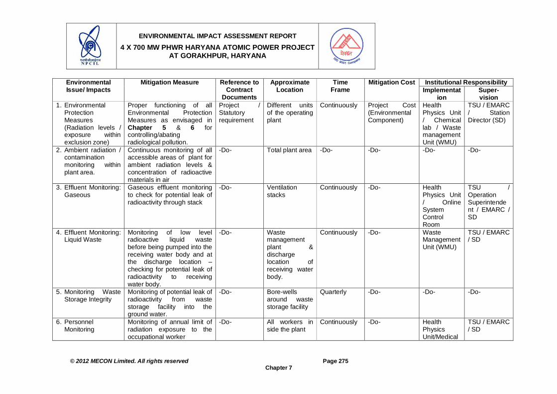
ENVIRONMENTAL IMPACT ASSESSMENT REPORT
4 X 700 MW PHWR HARYANA ATOMIC POWER PROJECT AT GORAKHPUR, HARYANA
© 2012 MECON Limited. All rights reserved Page 275
Chapter 7
Institutional Responsibility Environmental Issue/ Impacts
Mitigation Measure Reference to Contract
Documents
Approximate Location
Time Frame
Mitigation Cost Implementat
ion Super- vision
1. Environmental Protection Measures (Radiation levels / exposure within exclusion zone)
Proper functioning of all Environmental Protection Measures as envisaged in Chapter 5 & 6 for controlling/abating radiological pollution.
Project / Statutory requirement
Different units of the operating plant
Continuously Project Cost (Environmental Component)
Health Physics Unit / Chemical lab / Waste management Unit (WMU)
TSU / EMARC / Station Director (SD)
2. Ambient radiation / contamination monitoring within plant area.
Continuous monitoring of all accessible areas of plant for ambient radiation levels & concentration of radioactive materials in air
-Do- Total plant area -Do- -Do- -Do- -Do-
3. Effluent Monitoring: Gaseous
Gaseous effluent monitoring to check for potential leak of radioactivity through stack
-Do- Ventilation stacks
Continuously -Do- Health Physics Unit / Online System Control Room
TSU / Operation Superintendent / EMARC / SD
4. Effluent Monitoring: Liquid Waste
Monitoring of low level radioactive liquid waste before being pumped into the receiving water body and at the discharge location – checking for potential leak of radioactivity to receiving water body.
-Do- Waste management plant & discharge location of receiving water body.
Continuously -Do- Waste Management Unit (WMU)
TSU / EMARC / SD
5. Monitoring Waste Storage Integrity
Monitoring of potential leak of radioactivity from waste storage facility into the ground water.
-Do- Bore-wells around waste storage facility
Quarterly -Do- -Do- -Do-
6. Personnel Monitoring
Monitoring of annual limit of radiation exposure to the occupational worker
-Do- All workers in side the plant
Continuously -Do- Health Physics Unit/Medical
TSU / EMARC / SD

ENVIRONMENTAL IMPACT ASSESSMENT REPORT
4 X 700 MW PHWR HARYANA ATOMIC POWER PROJECT AT GORAKHPUR, HARYANA
© 2012 MECON Limited. All rights reserved Page 276
Chapter 7
Institutional Responsibility Environmental Issue/ Impacts
Mitigation Measure Reference to Contract
Documents
Approximate Location
Time Frame
Mitigation Cost Implementat
ion Super- vision
Unit 7. Radiation
Monitoring on Site Monitoring of gamma
radiation levels, continuously through field mounted environmental gamma dose logger
Watchdog monitoring at all
entry / exit points to the complex to detect movement of radioactive substances.
-Do- Specified 10 selected locations.
All entry exit
points
Continuously -Do- Health Physics Unit
-Do-
8. Radiological Monitoring in the Public Domain: Internal Radiation Levels & External Radiation Levels
Monitoring of external, internal and total radiation doses to the members of the public at various distances from the project.
-Do- In different identified zones within 30 km radius of the project.
Continuously -Do- ESL HPD, BARC / AERB / SD
9. Other Monitoring Requirements : Occupational Health and Safety
Periodic medical examination of all the plant personnel
-Do- All the plant personnel
Periodic -Do- Industrial Safety / HPU
TSU / EMARC / SD
10. Work Zone Noise levels
At all units of the plant -Do- -Do- -Do- Environmental Cost
Industrial Safety group
SD
11. Stack Monitoring for Diesel Generator Sets.
Monitoring of SO2, NOx, CO and PM at the out-let of all DG sets.
-Do- DG Sets Through out operation stage
-Do- Pollution Monitoring Agency.
Maintenance Group / SD
12. Stack Monitoring for Waste Incineration Facility.
Monitoring of SO2, NOx, CO and PM at the out-let of Waste Incinerator
-Do- Waste Incinerator location.
Through out operation stage
-Do- Waste Management Unit
TSU / EMARC / SD
13. Performance of Monitoring of sewage quality -Do- Project site -Do- -Do- Civil Maintenance
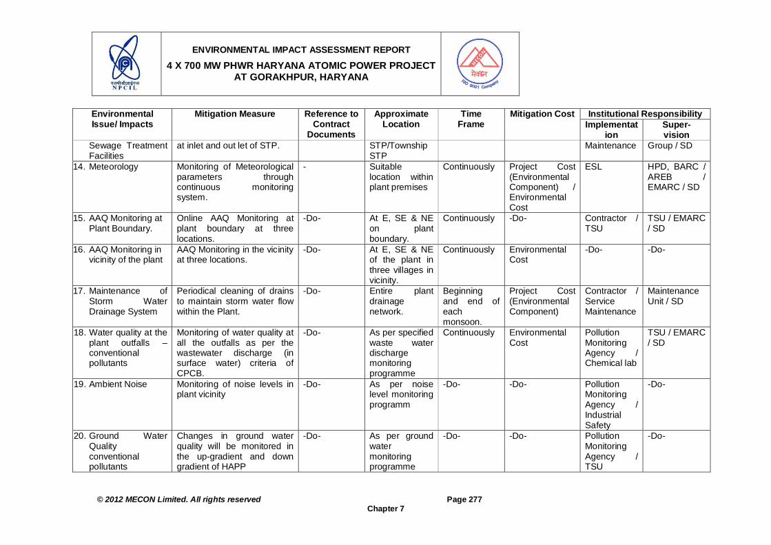
ENVIRONMENTAL IMPACT ASSESSMENT REPORT
4 X 700 MW PHWR HARYANA ATOMIC POWER PROJECT AT GORAKHPUR, HARYANA
© 2012 MECON Limited. All rights reserved Page 277
Chapter 7
Institutional Responsibility Environmental Issue/ Impacts
Mitigation Measure Reference to Contract
Documents
Approximate Location
Time Frame
Mitigation Cost Implementat
ion Super- vision
Sewage Treatment Facilities
at inlet and out let of STP. STP/Township STP
Maintenance Group / SD
14. Meteorology Monitoring of Meteorological parameters through continuous monitoring system.
- Suitable location within plant premises
Continuously Project Cost (Environmental Component) / Environmental Cost
ESL HPD, BARC / AREB / EMARC / SD
15. AAQ Monitoring at Plant Boundary.
Online AAQ Monitoring at plant boundary at three locations.
-Do- At E, SE & NE on plant boundary.
Continuously -Do- Contractor / TSU
TSU / EMARC / SD
16. AAQ Monitoring in vicinity of the plant
AAQ Monitoring in the vicinity at three locations.
-Do- At E, SE & NE of the plant in three villages in vicinity.
Continuously Environmental Cost
-Do- -Do-
17. Maintenance of Storm Water Drainage System
Periodical cleaning of drains to maintain storm water flow within the Plant.
-Do- Entire plant drainage network.
Beginning and end of each monsoon.
Project Cost (Environmental Component)
Contractor / Service Maintenance
Maintenance Unit / SD
18. Water quality at the plant outfalls – conventional pollutants
Monitoring of water quality at all the outfalls as per the wastewater discharge (in surface water) criteria of CPCB.
-Do- As per specified waste water discharge monitoring programme
Continuously Environmental Cost
Pollution Monitoring Agency / Chemical lab
TSU / EMARC / SD
19. Ambient Noise Monitoring of noise levels in plant vicinity
-Do- As per noise level monitoring programm
-Do- -Do- Pollution Monitoring Agency / Industrial Safety
-Do-
20. Ground Water Quality conventional pollutants
Changes in ground water quality will be monitored in the up-gradient and down gradient of HAPP
-Do- As per ground water monitoring programme
-Do- -Do- Pollution Monitoring Agency / TSU
-Do-

ENVIRONMENTAL IMPACT ASSESSMENT REPORT
4 X 700 MW PHWR HARYANA ATOMIC POWER PROJECT AT GORAKHPUR, HARYANA
© 2012 MECON Limited. All rights reserved Page 278
Chapter 7
Institutional Responsibility Environmental Issue/ Impacts
Mitigation Measure Reference to Contract
Documents
Approximate Location
Time Frame
Mitigation Cost Implementat
ion Super- vision
21. Soil quality - conventional pollutants
Monitoring of soil quality in plant vicinity.
As per soil quality monitoring programme
-Do- -Do- -Do- -Do-
22. Solid waste/Hazardous Waste generation and utililisation
Incineration of non-radioactive solid waste and disposal of Hazardous waste as per EMP.
-Do- All the units of the proposed plant generating solid wastes/HW
-Do- Project Cost (Environmental Component)
Central Material & Management / TSU
Chief Superintendent / SD
23. Municipal Solid Waste Disposal at Township
Disposal of municipal solid waste from township
Corporate responsibility
Entire Township
-Do- -Do- Contractor / Civil Maintenance
Maintenance Department / SD
24. Green Belt Proper implementation of green belt development and maintenance.
Project / Statutory requirement
green belt development area
-Do- -Do- Horticulture Unit / Service Maintenance
-Do-
25. House Keeping Cleanliness of work place -Do- All units of the plant.
-Do- -Do- All responsible units/ Service Maintenance
-Do-
26. Socio-economic Development
Structured interactions with the community to disseminate the measures taken and also to elicit suggestions for overall improvement for the development of the area
-Do- Stake Holders -Do- -Do- CSR Unit / Human Resource
SD
Note: EMP = environmental management plan, ESL = Environmental Survey Laboratory of the project, EMARC = Environmental Management Apex Review Committee formed at Plant level, CCE : Chief Construction Engineer; CSR Unit: Unit formed at the project to implement Corporate Social Responsibility goals; PM10 & PM2.5 = Particulate Matter of 10 & 2.5u size, SO2 = sulphur-di-oxide, NOx = Nitrogen Oxides, CO = Carbon Mono-oxide.

ENVIRONMENTAL IMPACT ASSESSMENT REPORT
4 X 700 MW PHWR HARYANA ATOMIC POWER PROJECT AT GORAKHPUR, HARYANA
© 2012 MECON Limited. All rights reserved Page 279
Chapter 7
Table 7.3: Part B: Yearly Environmental Monitoring Plan for Performance Indicators at Final Stage Environmental
component Project Stage
Parameters Location Frequency Standards Approximate cost (Rs)
Work zone Noise levels
Operation stage
As per OSHA work-zone noise norms.
All units of the plant 8 hr per shift continuous (to cover all shifts of operation at 12 shops unit)
once in each quarter during operation.
Applicable statutory standards
12x3shiftx4quartersX2000 =Rs. 288000
Manual Stack Monitoring for DG
Sets Stacks
Operation stage
All the parameters as specified by statutory authorities
All locations of DG Sets All 8 stacks in each quarter, i.e. 32 stacks per year
-Do- (8X4)X2000 =Rs. 64000
Manual Stack Monitoring for Waste
Incinerator
Operation stage
All the parameters as specified by statutory authorities
Waste Incinerator location 1 stacks per months, i.e. 12 stacks per year
-Do- (1x12)X2000 =Rs. 24000
Effluent Quality Operation stage
All the parameters as specified by statutory authorities
At inlet and outlet of different effluent treatment plants
Once in each month for two STP -Do- 2X2X12x8000 =Rs. 384000
Manual AAQ Monitoring
Operation stage
PM2.5, PM10, SO2, NOX, CO, O3 At three locations Once in each month (except in monsoon), continuous for 24 hr, during
operation.
-Do- 3X9X20000 =Rs. 900000
Waste Water Discharge Quality at
Plant Outfalls
Operation stage
All the parameters for waste water discharge in surface water
as specified by CPCB
All plant outfalls (three) Once in each month during operation at three outfall points.
-Do- 2X12x8000 =Rs. 288000
Ambient Noise levels Operation stage
As per National Ambient Noise Standard as per Environmental Protection Act, 1986 amended
2002
Six locations around the plant covering sensitive, residential
and commercial areas (as applicable).
Once / month during operation period at six locations.
-Do- 6X12X2,000 =Rs. 144000
Ground Water Quality Operation stage
As per IS 10500 Five locations around the Plant.
Once in each month at five locations during operation.
-Do- 5X12X8,000 = Rs. 480000
Soil quality Operation stage
Monitoring of Pb, Cr, Cd and other heavy metals.
Three locations around the plant.
Once in a year (during winters) during operation.
- 3X6,000 = Rs. 18000
Total 22,24,000 Total Estimated Monitoring Costs = Rs 22,24,000 (say 22.5 Lakhs) per year during the operation years of the HAPP. The cost, automatic weather monitoring station and continuous AAQ monitoring is not included in the cost estimated above. The same will be under “Project Operation Cost (Environmental Component)”. Note: Cd -Cadmium; CO - Carbon Monoxide; Cr - Chromium; O3-Ozone; NOx - Nitrogen Oxide; Pb - Plumbum, (lead); PM10-Particulate Matter up to 10u size; PM2.5-Particulate Matter up to 2.5u size; SO2 - Sulfur Dioxide; PM - Particulate Matter; ESL = Environmental Survey Laboratory, EMARC = Environmental Management Apex Review Committee; IS - India Standard; OSHA = . Occupational Safety and Health Administration, USA; CPCB = Central Pollution Control Board.

ENVIRONMENTAL IMPACT ASSESSMENT REPORT
4 X 700 MW PHWR HARYANA ATOMIC POWER PROJECT AT GORAKHPUR, HARYANA
© 2012 MECON Limited. All rights reserved Page 280
Chapter 7
7.6.2 Progress Monitoring and Reporting Arrangements
The rational for a reporting system is based on accountability to ensure that the measures proposed as part of the Environmental Monitoring Plan get implemented in the project. The monitoring and evaluation of the management measures are critical activities in implementation of the project. Monitoring involves periodic checking to ascertain whether activities are going according to the plans. It provides the necessary feedback for the project management to keep the programme on schedule. The responsibility matrix for environmental monitoring programme is given in Table 7.4.
Table 7.4: Reporting System for Environmental Monitoring Plan SN Details Indicators Stage Responsibility /
Supervision / Reporting
A. Pre-Construction Stage: Environmental Management Indicators and Monitoring Plan 1. Location for dumping of wastes
have to be identified and parameters indicative of environment in the area has to be reported.
Dumping locations Pre-construction
Contractor / Planning Section / PD
2. Suitable location for construction worker camps have to be identified and parameters indicative of environment in the area has to be reported.
Construction camps Pre-construction
Contractor / Civil Maintenance / HR (Human Resource)
3. Location of borrow areas have to be finalized from identified lists and parameters indicative of environment in the area has to be reported.
Borrow areas Pre-construction
Contractor / Civil Maintenance / Planning Section
B. Construction Stage: Environmental Condition Indicators Air quality Construction Contractor through
approved monitoring agency / Planning Unit / PD
Surface Water quality Construction -do- Ground Water quality Construction -do- Soil quality Construction -do-
1. The parameters to be monitored as per frequency, duration & locations of monitoring specified in the Environmental Monitoring Programme prepared
Noise level Construction -do- 2. Contractor shall report
implementation of the measures suggested for topsoil preservation to environmental expert / infrastructure team.
Top soil Construction Contractor / Civil Maintenance / Planning Unit / PD
C. Operation Stage: Management & Operational Performance Indicators Ambient radiation / contamination monitoring
Operation Health Physics Unit / ESL / TSU
Effluent Monitoring: Gaseous Operation Health Physics Unit / TSU
Effluent Monitoring: Liquid Waste
Operation WMU / Health Physics Unit / TSU
Monitoring Waste Storage Integrity
Operation WMU / TSU
1. Radiological Monitoring
Personnel Monitoring Operation Health Physics Unit

ENVIRONMENTAL IMPACT ASSESSMENT REPORT
4 X 700 MW PHWR HARYANA ATOMIC POWER PROJECT AT GORAKHPUR, HARYANA
© 2012 MECON Limited. All rights reserved Page 281
Chapter 7
SN Details Indicators Stage Responsibility / Supervision / Reporting / Medical Unit
Radiation Monitoring on Site Operation HPU / TSU Radiological Monitoring in the Public Domain: Internal Radiation Levels & External Radiation Levels
Operation ESL
Other Monitoring Requirements : Occupational Health and Safety
Operation Pant Medical Unit/Competent Authority / Industrial Safety
2. Work-zone noise levels As per statutory norms Operation Industrial Safety group / TSU
3. Stack Emissions DG sets & Waste Incineration Plant
All parameters as specified for stacks for DG sets / Incinerator by Statutory Authorities
Operation Approved Agency / TSU
4. Performance of Sewage Treatment Facilities
Inlet and Outlet characteristics of STP associated with plant & township
Operation Civil Maintenance / Maintenance Group
5. Meteorology, Ambient air quality, Waste water discharge through plant outfalls, Noise levels, Ground water and soil.
All parameters as specified by Statutory Authorities
Operation ESL
6. Maintenance of Storm Water Drainage System
Blockage of drainage system / overflowing of drains
Operation Contractor / Civil Maintenance
7. Hazardous waste re-disposal as specified by statutory authorities.
As per the notifications / guidelines specified by statutory authorities.
Operation CMM / Civil Maintenance
8. Municipal Solid Waste Disposal at Township
Proper implementation of the scheme
Operation Service Maintenance / Maintenance Group
9. Green Belt Development Survival rates of trees Operation Horticulture Unit / Civil Maintenance
10. House Keeping General Cleanliness of the plant and different units
Operation All responsible units / Service Maintenance
11. Socio-economic Development As per CSR Plan Pre-construction / Construction / Operation
Plant CSR Unit / Human Resources
7.6.3 Budgetary Provisions for Environmental Monitoring Plan
The list of equipment required in Chemical Laboratory / Waste Management Unit and Health Physics Unit / Environmental Survey Laboratory (ESL) for conventional pollutants is given in Table 7.5a. Whereas the list of equipment required for radiation/radioactivity measurements is given in Table 7.5b. Around 10% of Capital cost of the project is allocated to meet the requirements of reactor safety and environmental safety. The budgetary cost estimate for implementation of the environmental monitoring measures is elaborated in Table 7.3 (Part B). The summary of the cost of
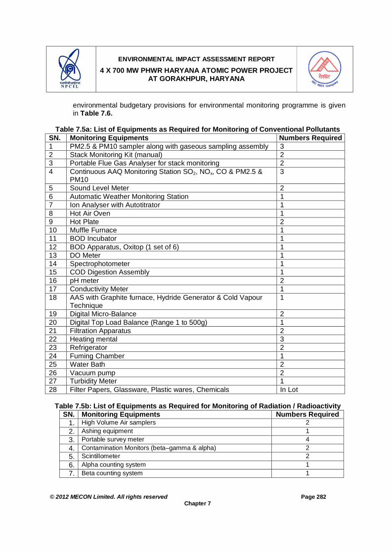
ENVIRONMENTAL IMPACT ASSESSMENT REPORT
4 X 700 MW PHWR HARYANA ATOMIC POWER PROJECT AT GORAKHPUR, HARYANA
© 2012 MECON Limited. All rights reserved Page 282
Chapter 7
environmental budgetary provisions for environmental monitoring programme is given in Table 7.6.
Table 7.5a: List of Equipments as Required for Monitoring of Conventional Pollutants
SN. Monitoring Equipments Numbers Required 1 PM2.5 & PM10 sampler along with gaseous sampling assembly 3 2 Stack Monitoring Kit (manual) 2 3 Portable Flue Gas Analyser for stack monitoring 2 4 Continuous AAQ Monitoring Station SO2, NOx, CO & PM2.5 &
PM10 3
5 Sound Level Meter 2 6 Automatic Weather Monitoring Station 1 7 Ion Analyser with Autotitrator 1 8 Hot Air Oven 1 9 Hot Plate 2 10 Muffle Furnace 1 11 BOD Incubator 1 12 BOD Apparatus, Oxitop (1 set of 6) 1 13 DO Meter 1 14 Spectrophotometer 1 15 COD Digestion Assembly 1 16 pH meter 2 17 Conductivity Meter 1 18 AAS with Graphite furnace, Hydride Generator & Cold Vapour
Technique 1
19 Digital Micro-Balance 2 20 Digital Top Load Balance (Range 1 to 500g) 1 21 Filtration Apparatus 2 22 Heating mental 3 23 Refrigerator 2 24 Fuming Chamber 1 25 Water Bath 2 26 Vacuum pump 2 27 Turbidity Meter 1 28 Filter Papers, Glassware, Plastic wares, Chemicals In Lot
Table 7.5b: List of Equipments as Required for Monitoring of Radiation / Radioactivity
SN. Monitoring Equipments Numbers Required 1. High Volume Air samplers 2 2. Ashing equipment 1 3. Portable survey meter 4 4. Contamination Monitors (beta–gamma & alpha) 2 5. Scintillometer 2 6. Alpha counting system 1 7. Beta counting system 1
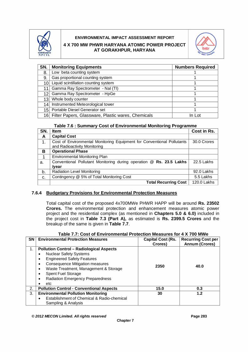
ENVIRONMENTAL IMPACT ASSESSMENT REPORT
4 X 700 MW PHWR HARYANA ATOMIC POWER PROJECT AT GORAKHPUR, HARYANA
© 2012 MECON Limited. All rights reserved Page 283
Chapter 7
SN. Monitoring Equipments Numbers Required 8. Low beta counting system 1 9. Gas proportional counting system 1 10. Liquid scintillation counting system 1 11. Gamma Ray Spectrometer - NaI (Tl) 1 12. Gamma Ray Spectrometer - HpGe 1 13. Whole body counter 1 14. Instrumented Meteorological tower 1 15. Portable Diesel Generator set 1 16. Filter Papers, Glassware, Plastic wares, Chemicals In Lot
Table 7.6 : Summary Cost of Environmental Monitoring Programme
SN. Item Cost in Rs. A Capital Cost 1. Cost of Environmental Monitoring Equipment for Conventional Pollutants
and Radioactivity Monitoring 30.0 Crores
B Operational Phase 1 Environmental Monitoring Plan
a. Conventional Pollutant Monitoring during operation @ Rs. 23.5 Lakhs /year
22.5 Lakhs
b. Radiation Level Monitoring 92.0 Lakhs c. Contingency @ 5% of Total Monitoring Cost 5.5 Lakhs Total Recurring Cost 120.0 Lakhs
7.6.4 Budgetary Provisions for Environmental Protection Measures
Total capital cost of the proposed 4x700MWe PHWR HAPP will be around Rs. 23502 Crores. The environmental protection and enhancement measures atomic power project and the residential complex (as mentioned in Chapters 5.0 & 6.0) included in the project cost in Table 7.3 (Part A), as estimated is Rs. 2399.5 Crores and the breakup of the same is given in Table 7.7.
Table 7.7: Cost of Environmental Protection Measures for 4 X 700 MWe SN Environmental Protection Measures Capital Cost (Rs.
Crores) Recurring Cost per
Annum (Crores) 1. Pollution Control – Radiological Aspects
Nuclear Safety Systems Engineered Safety Features Consequence Mitigation measures Waste Treatment, Management & Storage Spent Fuel Storage Radiation Emergency Preparedness etc
2350 40.0
2. Pollution Control - Conventional Aspects 15.0 0.3 3. Environmental Pollution Monitoring
Establishment of Chemical & Radio-chemical Sampling & Analysis
30 1.2

ENVIRONMENTAL IMPACT ASSESSMENT REPORT
4 X 700 MW PHWR HARYANA ATOMIC POWER PROJECT AT GORAKHPUR, HARYANA
© 2012 MECON Limited. All rights reserved Page 284
Chapter 7
SN Environmental Protection Measures Capital Cost (Rs. Crores)
Recurring Cost per Annum (Crores)
Health Physics & Bio-assay Sampling & Monitoring Facilities etc.
Enhancement of Environmental Survey, Sampling & Monitoring (Radiological & Non-radiological)
4. Green Belt in 33% for 200 ha. 1.5 lakhs / ha. 3.0 0.3 5. Social Welfare Measures
Health & Water Supply Facilities Education Matters Area Development / up-gradation Sanitation, etc 1.5 0.3
Total 2399.5 42.1 *Note: estimates are on the basis of 2011 cost
7.6.5 Procurement Schedule Construction of the project will be taken up in two stages of 2X700 MWe each. Planned schedule for the proposed two units of 1st stage will take about 60 months. Subsequent two units are expected to be four years later. The 1st stage project will be commissioned in 60 months from the “Zero-Date” which is reckoned as start of construction activities at site. Thus the procurement of different equipments for laboratory (Table 7.5a and 7.5b) shall be planned to be procured in yearly phase wise manner by the end of 48 months i.e. before the 1st stage of the plant gets under operation, so that the environmental enhancement measures are implemented with the start of the project.
7.7 UPDATING OF EMP The directives from MOEF and the regulations in force at any time shall govern the periodicity of monitoring. However it is suggested that the implementation of various measures recommended in the EMP be taken as EMPs in the ISO –14001 system to effectively implement the measures for continual improvement in environmental performance. OHSAS 18000 shall also be implemented for the total plant.


ENVIRONMENTAL IMPACT ASSESSMENT REPORT
4 X 700 MW PHWR HARYANA ATOMIC POWER PROJECT AT GORAKHPUR, HARYANA
© 2012 MECON Limited. All rights reserved Page 285
Chapter 8
CHAPTER 8 : ADDITIONAL STUDIES: PUBLIC CONSULTATION & SOCIAL IMPACT ASSESSMENT
8.0 ADDITIONAL STUDIES: PUBLIC CONSULTATION & SOCIAL IMPACT
ASSESSMENT 8.1 PUBLIC CONSULTATION
Based on the directive from Environmental Appraisal Committee (EAC), Ministry of Environment & Forest (MoEF) in their 9th EAC meeting held on September 2010 and vide their minutes for the said meeting dated 13th October 2010 issued the “Terms of Reference” for preparation of EIA / EMP study for the Atomic Power Project at Fatehabad Haryana. On the basis of the TOR the draft EIA report is prepared and submitted an application to Sub-Regional Officer, Haryana Pollution Control Board (HPCB), Hisar for organizing Public Hearing for HAPP. The HPCB Office notified on --------------, 2012, the date of Public Hearing as ---------------- at HAPP site, Village Gorakhpur, District Fatehabad. Public hearing process was carried out by Haryana Pollution Control Board on ------------as per the guidelines given in Environmental Impact Notification, 2006 issued vide no. S.O. 1533(E), dated the 14th September, 2006 and its amendment vide S.O. 3067 (E) dated 1st December, 2009. During the process of public hearing Sub Regional Office Haryana Pollution Control Board (HPCB) received submissions / queries / observations from Project Affected Persons (PAPs), members of public and NGOs regarding various aspects of the project, process of public hearing and EIA report. The minutes of the meeting (MoM) of public hearing and submissions (in English and Hindi language) received are numbered and complied as Vol-III. The English translation of the Hindi submissions is given on the rear side of the respective Hindi pages in Vol-III. The minutes of meeting of Public hearing and submissions by public members and responses thereof by NPCIL has been compiled and being submitted as per below:
Annexure VI: Proceedings of Public Hearing and Commitments from NPCIL – English.
Annexure VII: Proceedings of Public Hearing and Commitments from NPCIL – Hindi.
Public Hearing Observations Place of Inclusion in Report To be Included after Public Hearing
8.2 SOCIAL IMPACT ASSESSMENT 8.2.1 Introduction
All industrial projects have social and economic linkages. Therefore, putting up a new project and/or modernization/ expansion of existing projects has impact on the socio–economic environment of the locality around it. This impact may be marginal or non–

ENVIRONMENTAL IMPACT ASSESSMENT REPORT
4 X 700 MW PHWR HARYANA ATOMIC POWER PROJECT AT GORAKHPUR, HARYANA
© 2012 MECON Limited. All rights reserved Page 286
Chapter 8
marginal. The intensity of impact may depend upon the various social and environmental factors associated with it and the extent of change caused by the project to alter the existing equilibrium of the socio-economic system. Influx of people from outside during various stages of the project may also alter the existing cultural identity of the local people. Further, there is a cash flow associated with the project which may affects the existing socio–economic activities and introduces many more new activities associated with the project to which the local people have strong adherence. M/s NPCIL has proposed an atomic power plant near Gorakhpur village of Fatehabad district, Haryana.. The various activities of the proposed projects are likely to stimulate the existing socio–economic environment in the surrounding area. The influx of money and various construction activities may not only change the economic status of the area but also influence the existing cultural scenario. This impact is expected to be more in the area closer to the site, which decreases with increase of distance from the site.
8.2.2 Objectives
The proposed project will have a widespread impact on the social and economic conditions of the people of the region in terms of direct and indirect employment, skill diversification, infrastructure development, business development etc. On this backdrop, the present study is directed towards the following objectives:
i) To assess the present appraisal of the demographic profile of the study area ii) To assess the agricultural situation and to assess the impact of the project on
agricultural situation; iii) To assess the impact of the project on pattern of demand; iv) To examine the impact of the project on consumption pattern; v) To examine the employment and income effects of the project; vi) Assessment of the educational status of the people and to explore the impact of
the project on education; vii) To ascertain the impact of the project on industrialization in the study area; viii) To examine the impact of the project on community development activities; ix) To analyze peoples' perception regarding impact of the project
8.2.3 Methodology Adopted for the Study
The methodology adopted for the study is based on the following: Review of Secondary Data Review of secondary data, such as District Census Statistical Handbooks 2001 for the parameters of demography, occupational structure of people within the general study area of 10km radius around the proposed plant site. The secondary data supplemented the primary data collected through direct field survey.
Field Survey Baseline data on socio-economic parameters were generated using information available with Govt. agencies, census data etc.

ENVIRONMENTAL IMPACT ASSESSMENT REPORT
4 X 700 MW PHWR HARYANA ATOMIC POWER PROJECT AT GORAKHPUR, HARYANA
© 2012 MECON Limited. All rights reserved Page 287
Chapter 8
Socio-economic survey was carried out covering all the villages / towns of the study area to record awareness, opinion, apprehensions, quality of life and expectations of the local people about the proposed plant. The opinion of local people about the proposed expansion plan was obtained through socio-economy survey of the villages / towns in the study area.
A brief about the sampling design adopted for the field survey is described below. The survey has been conducted through specially designed questionnaire covering every aspect of the present study. In addition to the field data, secondary data / information collected, compiled and published by different Governmental agencies / departments were also collected and utilized appropriately.
Sampling For selection of respondents from the study area, Two Stage Random Sampling has been adopted. In the first stage, villages are selected and in the second stage, households/ respondents are selected. From each selected village, the respondents are selected randomly to account intra-village variability among the respondents for the character under study. As the variability of the characters under in each strata study does not vary widely among the households, a smaller sample size is expected to represent the population. Samples of 24 respondents were drawn from the study area. The sample covers an estimated 65 persons (Socio-economic survey on questionnaire to be conducted).
Composition of the Questionnaire
Households/respondents were interviewed with the structured questionnaire specifically designed for this study keeping in view the objectives of the study. The questionnaire consists of following major sections: a) Demographic profile of the households a) Educational status b) Information on agricultural situation c) Employment (sources of employment) d) Income (income from various sources) e) Information on family budget f) Consumption and saving g) Respondents' perception about the project
Analytical Framework / Methodology for Compilation & Analysis The major methods used as tools of analysis in this study are given below :
1. Regression: Simple linear regression of the following type is considered
Yi = a + b Xi + Ui
Where, Y is dependent variable, X is explanatory variable and U is the stochastic error term having its usual properties.
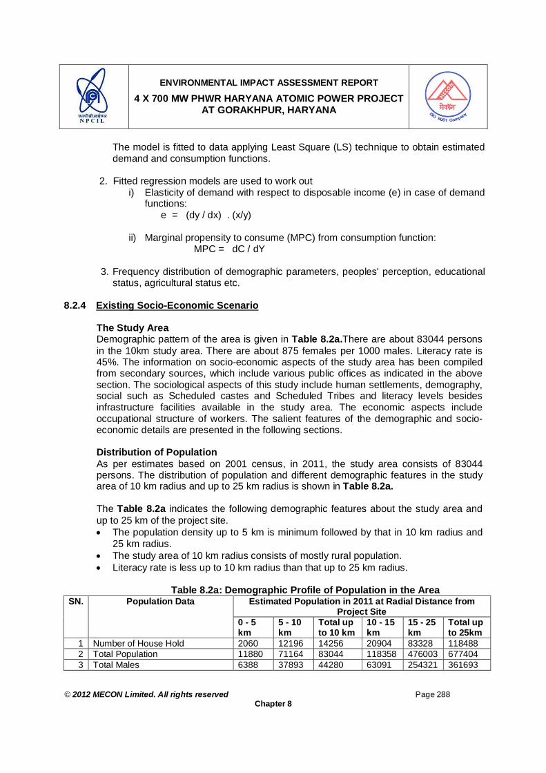
ENVIRONMENTAL IMPACT ASSESSMENT REPORT
4 X 700 MW PHWR HARYANA ATOMIC POWER PROJECT AT GORAKHPUR, HARYANA
© 2012 MECON Limited. All rights reserved Page 288
Chapter 8
The model is fitted to data applying Least Square (LS) technique to obtain estimated demand and consumption functions.
2. Fitted regression models are used to work out
i) Elasticity of demand with respect to disposable income (e) in case of demand functions:
e = (dy / dx) . (x/y)
ii) Marginal propensity to consume (MPC) from consumption function: MPC = dC / dY
3. Frequency distribution of demographic parameters, peoples' perception, educational
status, agricultural status etc.
8.2.4 Existing Socio-Economic Scenario
The Study Area Demographic pattern of the area is given in Table 8.2a.There are about 83044 persons in the 10km study area. There are about 875 females per 1000 males. Literacy rate is 45%. The information on socio-economic aspects of the study area has been compiled from secondary sources, which include various public offices as indicated in the above section. The sociological aspects of this study include human settlements, demography, social such as Scheduled castes and Scheduled Tribes and literacy levels besides infrastructure facilities available in the study area. The economic aspects include occupational structure of workers. The salient features of the demographic and socio-economic details are presented in the following sections. Distribution of Population As per estimates based on 2001 census, in 2011, the study area consists of 83044 persons. The distribution of population and different demographic features in the study area of 10 km radius and up to 25 km radius is shown in Table 8.2a. The Table 8.2a indicates the following demographic features about the study area and up to 25 km of the project site. The population density up to 5 km is minimum followed by that in 10 km radius and
25 km radius. The study area of 10 km radius consists of mostly rural population. Literacy rate is less up to 10 km radius than that up to 25 km radius.
Table 8.2a: Demographic Profile of Population in the Area Estimated Population in 2011 at Radial Distance from
Project Site SN. Population Data
0 - 5 km
5 - 10 km
Total up to 10 km
10 - 15 km
15 - 25 km
Total up to 25km
1 Number of House Hold 2060 12196 14256 20904 83328 118488 2 Total Population 11880 71164 83044 118358 476003 677404 3 Total Males 6388 37893 44280 63091 254321 361693
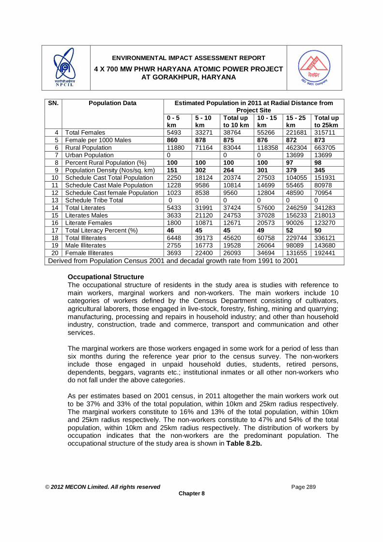
ENVIRONMENTAL IMPACT ASSESSMENT REPORT
4 X 700 MW PHWR HARYANA ATOMIC POWER PROJECT AT GORAKHPUR, HARYANA
© 2012 MECON Limited. All rights reserved Page 289
Chapter 8
Estimated Population in 2011 at Radial Distance from Project Site
SN. Population Data
0 - 5 km
5 - 10 km
Total up to 10 km
10 - 15 km
15 - 25 km
Total up to 25km
4 Total Females 5493 33271 38764 55266 221681 315711 5 Female per 1000 Males 860 878 875 876 872 873 6 Rural Population 11880 71164 83044 118358 462304 663705 7 Urban Population 0 0 0 13699 13699 8 Percent Rural Population (%) 100 100 100 100 97 98 9 Population Density (Nos/sq. km) 151 302 264 301 379 345
10 Schedule Cast Total Population 2250 18124 20374 27503 104055 151931 11 Schedule Cast Male Population 1228 9586 10814 14699 55465 80978 12 Schedule Cast female Population 1023 8538 9560 12804 48590 70954 13 Schedule Tribe Total 0 0 0 0 0 0 14 Total Literates 5433 31991 37424 57600 246259 341283 15 Literates Males 3633 21120 24753 37028 156233 218013 16 Literate Females 1800 10871 12671 20573 90026 123270 17 Total Literacy Percent (%) 46 45 45 49 52 50 18 Total Illiterates 6448 39173 45620 60758 229744 336121 19 Male Illiterates 2755 16773 19528 26064 98089 143680 20 Female Illiterates 3693 22400 26093 34694 131655 192441
Derived from Population Census 2001 and decadal growth rate from 1991 to 2001 Occupational Structure
The occupational structure of residents in the study area is studies with reference to main workers, marginal workers and non-workers. The main workers include 10 categories of workers defined by the Census Department consisting of cultivators, agricultural laborers, those engaged in live-stock, forestry, fishing, mining and quarrying; manufacturing, processing and repairs in household industry; and other than household industry, construction, trade and commerce, transport and communication and other services.
The marginal workers are those workers engaged in some work for a period of less than six months during the reference year prior to the census survey. The non-workers include those engaged in unpaid household duties, students, retired persons, dependents, beggars, vagrants etc.; institutional inmates or all other non-workers who do not fall under the above categories. As per estimates based on 2001 census, in 2011 altogether the main workers work out to be 37% and 33% of the total population, within 10km and 25km radius respectively. The marginal workers constitute to 16% and 13% of the total population, within 10km and 25km radius respectively. The non-workers constitute to 47% and 54% of the total population, within 10km and 25km radius respectively. The distribution of workers by occupation indicates that the non-workers are the predominant population. The occupational structure of the study area is shown in Table 8.2b.

ENVIRONMENTAL IMPACT ASSESSMENT REPORT
4 X 700 MW PHWR HARYANA ATOMIC POWER PROJECT AT GORAKHPUR, HARYANA
© 2012 MECON Limited. All rights reserved Page 290
Chapter 8
The marginal workers constitute 17%, 16% and 13% of population within 5 km, 10 km and 25 km radius of the project site. The marginal workers can possibly be the pool for unskilled labour in the area during the construction stage of the plant.
Table 8.2b: Occupational Structure in the Area
Estimated Population in 2011 at Radial Distance from
Project Site SN. Population Data
0 - 5 km
5 - 10 km
Total Up to 10 km
10 - 15 km
15 - 20 km
Total Up to 25 km
1. Total Population 11880 71164 83044 118358 476003 677404 2. Total Worker Population 7129 37081 44210 55243 211959 311411 3. Total Worker male 3960 21064 25024 33745 134920 193689 4. Total Worker Female 3169 16018 19186 21498 77039 117723 5. Total Working Population % to
Total Population 60 52 53 47 45 46
6. Total Working Male % to Male Population
62 56 57 53 53 54
7. Total Working Female % to Female Population
58 48 49 39 35 37
8. Main Workers Total 5114 25429 30543 36463 157261 224266 9. Main Workers Male 3154 17309 20463 28413 117006 165881 10. Main Workers female 1960 8120 10080 8050 40255 58385 11. Total Main Workers (%) 43 36 37 31 33 33 12. Total Main Workers Male (%) 49 46 46 45 46 46 13. Total Main Workers Female (%) 36 24 26 15 18 18 14. Total Cultivators 4079 16978 21056 19878 75851 116785 15. Total Cultivators Male 2443 10853 13295 14640 52019 79954 16. Total Cultivators female 1636 6125 7761 5238 23833 36831 17. Main Agricultural Labour 406 3328 3734 4144 21281 29159 18. Main Agriculture Labour Male 248 2454 2701 3005 14136 19843 19. Main Agriculture Labour Female 159 874 1033 1139 7145 9316 20. Main Household Industry Labour
Total 75 554 629 823 3788 5239
21. Main Household Industry laboure Male
70 381 451 638 2874 3963
22. Main House Hold Industry Labour Female
5 173 178 185 914 1276
23. Main Other Workers Total 554 4570 5124 11619 56341 73084 24. Main Other Workers Male 394 3621 4015 10130 47978 62123 25. Main Other Workers Female 160 949 1109 1489 8364 10961 26. Marginal Worker Total 2015 11653 13668 18780 54698 87145 27. Marginal Worker Male 806 3755 4561 5333 17914 27808 28. Marginal Worker Female 1209 7898 9106 13448 36784 59338 29. Total Marginal Workers % to
Total Population 17 16 16 16 11 13
30. Male Marginal Workers % to Male Population
13 10 10 8 7 8
31. Female Marginal Workers % to 22 24 23 24 17 19

ENVIRONMENTAL IMPACT ASSESSMENT REPORT
4 X 700 MW PHWR HARYANA ATOMIC POWER PROJECT AT GORAKHPUR, HARYANA
© 2012 MECON Limited. All rights reserved Page 291
Chapter 8
Estimated Population in 2011 at Radial Distance from Project Site
SN. Population Data
0 - 5 km
5 - 10 km
Total Up to 10 km
10 - 15 km
15 - 20 km
Total Up to 25 km
Female Population 32. Non Working Population Total 4751 34083 38834 63115 264044 365993 33. Non Working Population Male 2428 16829 19256 29346 119401 168004 34. Non Working Population Female 2324 17254 19578 33769 144643 197989 35. Total Non-workers % to Total
Population 40 48 47 53 55 54
36. Male Non-workers % to Male Population
38 44 43 47 47 46
37. Female Non-workers % to Female Population
42 52 51 61 65 63
Source: District Census Hand Book – 20011, National Informatic Center, New Delhi
Infrastructure Facilities About 4/5th of the 10 km study area falls in Fatehabad district and about 1/5th falls in Hisar district. The infrastructure and amenities available in the district denotes the economic well being of the region. The area as a whole possesses moderate level of infrastructural facilities.
A review of infrastructure facilities available in the area has been done based on the information given in Fatehabad District Statistical Abstract 2008 – 09 and the data of District Socio-economic Re-evaluation, Fatehabad 2008 – 09. Similar type of information is not available for Hisar District. It is presumed that the infrastructure facilities available in 4/5th part of the study area will also be present in remaining area of the study area. Moreover, Fatehabad district has been carved out of Hisar district in 1997. Therefore the Infrastructure facilities available in the Fatehabad district are described in the subsequent sections as those available in the study area. The geographical area of Fatehabad district is about 2538 km2.
Educational Facilities The available educational facilities in the blocks falling in study area are given in Table 8.2c. As per the District Education Officers of Fatehabad and Hisar districts the education facilities in the two district in general and in particular in the blocks falling in study area is adequate and as per Government of India norms, i.e. availability of primary school within one kilometer of habitation, middle school within 3 kilometer of habitation and high school and secondary education within 5 kilometer of habitation. The above requirements are almost met in the area considering the fact that a middle school, high school and secondary school also have the lower level classes, i.e. from standard one to onwards standards.

ENVIRONMENTAL IMPACT ASSESSMENT REPORT
4 X 700 MW PHWR HARYANA ATOMIC POWER PROJECT AT GORAKHPUR, HARYANA
© 2012 MECON Limited. All rights reserved Page 292
Chapter 8
Table 8.2c: Educational Facilities in Blocks in the Study Area Number of Institution
Fatehabad District Blocks Hisar District Block SN. Institution Type
Bhatu Kalan
Bhuna Fatehabad Agroha
1. Primary schools 39 52 107 36 2. Middle schools 10 4 17 5 3. High School 10 15 25 16 4. Senior Secondary School 9 10 14 6 Source : District Education Officers of Fatehabad and & Hisar Districts
Health Facilities Different types of health facilities including hospital and dispensaries are available in the district. The level of health facilities is found to be moderate. The available health facilities as per Fatehabad District Statistical Abstract are given in Table 8.2d. As per Civil Surgeon Fatehabad and Hisar District there is one sub-centre on 5000 population, one Primary Health Centre (PHC) on 30,000 population, one Community Health Centre (CHC) on 1,20,000 population and a General Hospital at District level. In general the sub-centres are at Panchyat level, CHC is at Block level and Sub-divisional Hospital (SDH) is at sub-division level and General Hospital (GH) is at district level. At sub-centres Multipurpose Health workers are there (one male and one female), at PHC’s two medical officers are posted, at CHCs four medical officers and one incharge is posted and at GH specialists of major discipline like, general surgery, orthopedics, general physician, pediatrics, gynecology, anesthesia, etc are posted. As per the civil surgeon the medical facilities are adequate in the area and as per government of India norms.
Table 8.2d: Health Facilities in Fatehabad District
District SN. Type of Health Institution Fatehabad Hisar
1. Sub-centers 103 198 2. Primary Health Center 16 35 3. Community Health Centre 4 8 4. Sub Divisional Hospital 1 2 5. General Hospital 1 1 Source : Civil Surgeon Fatehabad & Hisar District 2012
The number of patients treated vis-à-vis falling ill in the Fatehabad and Hisar district is given in Table 8.2e. Out of the total population overall about 10% in Fatehabad and 5% of the population per year falls sick to the extent to be admitted in hospital. The percent population getting treatment in out-door is 110% for Fatehabad and 63% for Hisar. The figures are low in Hisar may be due to more private medical fascilities in the district the population seek their medical requirement from private sources. The figure may overall indicate the availability of Government Hospitals and access of masses to the same in the two districts.

ENVIRONMENTAL IMPACT ASSESSMENT REPORT
4 X 700 MW PHWR HARYANA ATOMIC POWER PROJECT AT GORAKHPUR, HARYANA
© 2012 MECON Limited. All rights reserved Page 293
Chapter 8
Table 8.2e: Number of Patients Treated in Health Institution in Fatehabad and Hisar District (2011 data)
District SN.
Particulars Fatehabad Hisar
1 Population 2001 423438 1537117 2 Projected Population 2011 529298 1921396 3 New Indoor Patient 33396 47771 4 New Out Door Patient 488131 900396 5 New & Old Indoor Patient 54462 88456 6 New & Old Outdoor Patient 584411 1211704 7 Total Patients Treated 638873 1300160 8 Percent Population Getting Treatment in Indoor 10 5 9 Percent Population Getting Treatment in Outdoor 110 63
10 Percent Population Getting Treatment in Indoor & Out Door 121 68
Health Status in the Study Area The health status in the district was assessed by the information provided by the Civil Surgeon Fatehabad and Hisar. The common diseases are viral fever, cough and colds, diarrhea and enteric fever are the prominent diseases in the region. During monsoon viral fever, diarrhea and cough are very common diseases and could be attributed to the rains, which generally contaminate water in the region and also the moist climate. Tuberculosis is also disease observed in the region, however in a very less proportion. The major communicable diseases prevalent in the study area are presented in Table 8.2f.
Table 8.2f: Principal Communicable Disease Occurrence Pattern in Fatehabad and Hisar District (Data 2011)
Type of Diseases Fatehabad Hisar Total Disease Occurrence (%)
Cholera (Lab Confirmed) 0 0 0 0.00 Acute Dairrhoeal Diseases 6478 8721 15199 9.18 Diptheria 0 0 0 0.00 Tetanus other than Neonatal 0 0 0 0.00 Neonatal Tetanus 0 0 0 0.00 Whooping Cough 0 0 0 0.00 Measles 1 1 2 0.00 Acute Respiratory Infection (Including Influenza and Excluding Pneumonia)
86397 57272 143669 86.81
Pneumonia 235 131 366 0.22 Enteric fever 1255 497 1752 1.06 Hepatitis A 286 122 408 0.25 Hepatitis B 34 5 39 0.02 Hepatitis C, D, E 0 0 0 0.00 Meningococcal Meningitis 0 0 0 0.00 Rabies 108 0 108 0.07 AIDS (As Reported to NACO) 496 132* 496 0.30
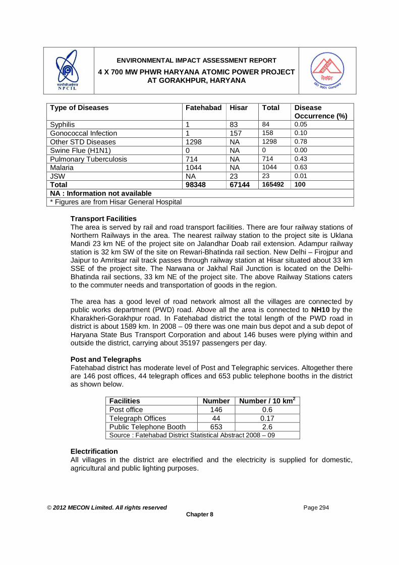
ENVIRONMENTAL IMPACT ASSESSMENT REPORT
4 X 700 MW PHWR HARYANA ATOMIC POWER PROJECT AT GORAKHPUR, HARYANA
© 2012 MECON Limited. All rights reserved Page 294
Chapter 8
Type of Diseases Fatehabad Hisar Total Disease Occurrence (%)
Syphilis 1 83 84 0.05 Gonococcal Infection 1 157 158 0.10 Other STD Diseases 1298 NA 1298 0.78 Swine Flue (H1N1) 0 NA 0 0.00 Pulmonary Tuberculosis 714 NA 714 0.43 Malaria 1044 NA 1044 0.63 JSW NA 23 23 0.01 Total 98348 67144 165492 100 NA : Information not available * Figures are from Hisar General Hospital
Transport Facilities The area is served by rail and road transport facilities. There are four railway stations of Northern Railways in the area. The nearest railway station to the project site is Uklana Mandi 23 km NE of the project site on Jalandhar Doab rail extension. Adampur railway station is 32 km SW of the site on Rewari-Bhatinda rail section. New Delhi – Firojpur and Jaipur to Amritsar rail track passes through railway station at Hisar situated about 33 km SSE of the project site. The Narwana or Jakhal Rail Junction is located on the Delhi-Bhatinda rail sections, 33 km NE of the project site. The above Railway Stations caters to the commuter needs and transportation of goods in the region. The area has a good level of road network almost all the villages are connected by public works department (PWD) road. Above all the area is connected to NH10 by the Kharakheri-Gorakhpur road. In Fatehabad district the total length of the PWD road in district is about 1589 km. In 2008 – 09 there was one main bus depot and a sub depot of Haryana State Bus Transport Corporation and about 146 buses were plying within and outside the district, carrying about 35197 passengers per day. Post and Telegraphs Fatehabad district has moderate level of Post and Telegraphic services. Altogether there are 146 post offices, 44 telegraph offices and 653 public telephone booths in the district as shown below.
Facilities Number Number / 10 km2 Post office 146 0.6 Telegraph Offices 44 0.17 Public Telephone Booth 653 2.6 Source : Fatehabad District Statistical Abstract 2008 – 09
Electrification All villages in the district are electrified and the electricity is supplied for domestic, agricultural and public lighting purposes.

ENVIRONMENTAL IMPACT ASSESSMENT REPORT
4 X 700 MW PHWR HARYANA ATOMIC POWER PROJECT AT GORAKHPUR, HARYANA
© 2012 MECON Limited. All rights reserved Page 295
Chapter 8
Drinking Water Facility All the villages in Fatehabad District have been provided drinking water facilities under drinking water project. Police Station The number of Police station and Chowki in Fatehabad and Hisar district is as follows:
Facilities Fatehabad Hisar Police Station 9 11 Chowki 12 20 Source : State Statistical Abstract
8.2.5 Prediction of Socio-Economic Impact
Agriculture The 10 km study area comprises of about 4/5th and 1/5th of Fatehabad district and Hisar district, respectively. Block wise, Bhuna, Bhatukalan and Fatehabad blocks (Fatehabad district) comprises 3/5th, 1/10th and 1/10th, respectively. Agroha block (Hisar district) comprises 1/5th of the study area. To have an overall idea of land holding pattern of the study area, the distribution of number of holdings in different holding size of the blocks from Fatehabad district only have been reviewed and presented in Table 8.3a. From Table 8.3a it can be seen that the land holding pattern of all the three blocks of Fatehabad district is similar, however, similar data for Agroha block of Hisar district is not available. Since Agroha block comprises only 1/5th of the study area it may be presumed that the land holding pattern in the 10km study area will be almost similar as depicted in the three blocks. Marginal farmers are about 35% (of total farming population), holding about 7% of the land in the study area. Small farmers constitute 22%, holding about 12% of land area and semi-medium and medium farmers are 40%, holding about 63% of land area. These three categories together constitute 97% of farmers, holding 82% of land area. It is interesting to note that there are 3% large farmers holding about 18% of land area. Pictorial view of the distribution of land holding is shown in Fig. 8.1. The land holding pattern of the above blocks have been reviewed and presented in Table 8.3a.
Table 8.3a: Distribution of Landholding in the Study Area
Bhuna Bhatu-kalan Fatehabad Total SN Blocks Number Area Number Area Number Area Number Area
Absolute 4743 2466 4515 2344 8400 4355 17658 9165 1 Marginal (< 1 Ha.) % 35 7 35 7 35 7 35 7
Absolute 2981 4228 2838 4018 5280 7467 11099 15713 2 Small (1 – 2 Ha.) % 22 12 22 12 22 12 22 12
Absolute 3117 8809 2967 8370 5520 15556 11604 32735 3 Semi Medium (2 –
4 ha.) % 23 25 23 25 23 25 23 25

ENVIRONMENTAL IMPACT ASSESSMENT REPORT
4 X 700 MW PHWR HARYANA ATOMIC POWER PROJECT AT GORAKHPUR, HARYANA
© 2012 MECON Limited. All rights reserved Page 296
Chapter 8
Bhuna Bhatu-kalan Fatehabad Total SN Blocks Number Area Number Area Number Area Number Area
Absolute 2304 13390 2193 12722 4080 23645 8577 49757 4 Medium (4-10 ha.) % 17 38 17 38 17 38 17 38
Absolute 407 6343 387 5926 720 11202 1514 23471 5 Large (>10 ha.) % 3 18 3 18 3 18 3 18
Absolute 13552 35236 12901 33480 24000 62225 50453 130941 Total % 100 100 100 100 100 100 100 100
Source : Comprehensive District Agriculture Plan (C-DAP) District Fatehabad Haryana, XIth Five Year Plan
Marginal (< 1 Ha.)35%
Small (1 – 2 Ha.)22%
Semi Medium (2 – 4 ha.)23%
Medium (4-10 ha.)17%
Large (>10 ha.)3%
Fig. 8.1: Land Holding Pattern in the Study Area
Table 8.3b depicts the cropping pattern and production in the Fatehabad District. Matching data for Hisar are not available and since Agroha block of Hisar District covers only 1/5th of the study area thus it is presumed that the agricultural pattern as present for Fatehabd district will also be there for the entire study area (including the 1/5th of Agroha block of Hisar). The crops are grown during Rabi, Kharif and summer seasons. The cropping pattern in the general study area reveals that wheat, cotton and paddy are the most predominant crop followed by Guar, Bajra and Sarson, etc.
Table 8.3b: Cropping Pattern of the Study Area
Area under Crop SN. Cropping Pattern Absolute (ha) % Area
Yield kg/ha
1. Paddy 70243 17 3952 2. Wheat 177591 43 5081 3. Sarson 13320 3 2126

ENVIRONMENTAL IMPACT ASSESSMENT REPORT
4 X 700 MW PHWR HARYANA ATOMIC POWER PROJECT AT GORAKHPUR, HARYANA
© 2012 MECON Limited. All rights reserved Page 297
Chapter 8
Area under Crop SN. Cropping Pattern Absolute (ha) % Area
Yield kg/ha
4. Bajra 12000 3 2407 5. Cotton 91137 22 625 6. Guar 29000 7 - 7. Other Crops & Horticulture 15379 4 - 8. Gross Cropped Area 408670 100 - 9. Net Cultivated Area 219201 - - 10. Irrigation by Canal 100001 46.23% - 11. Irrigation by Tube well 98397 45.49% -
Cropping intensity in the area is high (207%). Average investment in agriculture is Rs 12005 per acre (Table 8.3c). Cropping intensity indicates multi-crop culture. Even then agriculture is profitable as net return is Rs 27239 per acre.
Table 8.3c: Cropping intensity, net return & investment
Item Value
Cropping intensity (%) 207 Net return (Rs/acre) 27239 Average investment (Rs/acre) 12005
Agricultural situation of the study area indicates that agriculture in this area is good using latest development in the country. The project is not going to cause any damage to agricultural situation of the study area. Instead, it is likely to help agriculture by way of providing income from non-farm sources
Pattern of Demand The survey reveals that the respondents spend major portion of their disposable income on food items. However, there has been a growing tendency among the respondents of allocating higher expenditure on non-food items although their basket of consumption have only few items other than food. To go to the details of their pattern of demand, income elasticity of demand is calculated by fitting demand functions. Table 8.3d presents the results of the regression analysis conducted for fitting the demand functions. It is observed that all the demand functions give uniformly good fits to the data because R2 in all the cases are found to be quite high. Moreover, as indicated by t-test, the relevant parameter of the demand functions is found to be statistically highly significant at 1% level. The income elasticity of demand as measured from the fitted functions is 0.998 and 0.996 for food and non-food items respectively.
The inelastic nature of demand for food items indicates their necessity for these items to the households. The non-food items are found to be elastic to the income of households. This implies that for any additional income, households will spend for non-food items including luxurious goods.

ENVIRONMENTAL IMPACT ASSESSMENT REPORT
4 X 700 MW PHWR HARYANA ATOMIC POWER PROJECT AT GORAKHPUR, HARYANA
© 2012 MECON Limited. All rights reserved Page 298
Chapter 8
Table 8.3d: Demand Functions for Food and Non-food Items Regression parameters Demand Function Item
log a b R2
Dij = a * Ybj * U
Where, Dij = Demand for the ith item by jth
respondent. Yj= Disposable income of the jth
respondent
Food
Non-Food
0.312
-0.084
0.993
(116.4)*
0.942 (71.9)*
0.998
0.996
Figures in ( ) indicate t - values * Significant at 1% level.
With the implementation of the project and development of the locality, new type of demand pattern may emerge which is likely to place more importance on consumer goods and quality products. This is not a bad impact provided considerable income is generated due to the project and sufficient income is earned by them; otherwise, if the shift is a substitution of necessary food requirements then it is not desirable in true socio-economic sense.
Employment and Income Effect Occupational pattern of the study area reveals that about 68% of the income is generated from agriculture and 24% from services. 8% of the income is generated from business (Fig. 8.2).
Cultivation68%
Service24%
Business8%
0%
0%
Fig. 8.2: Occupational Structure of the Study Area

ENVIRONMENTAL IMPACT ASSESSMENT REPORT
4 X 700 MW PHWR HARYANA ATOMIC POWER PROJECT AT GORAKHPUR, HARYANA
© 2012 MECON Limited. All rights reserved Page 299
Chapter 8
Direct Employment Agriculture, business, and service are major sources of income in the study area. However, unemployment is quite common in the study area. The project has employment generation potential by way of recruiting local people directly for different activities of the project, specifically at the construction phase. It is expected that substantial portion of the investment in this project will trickle down to the local people in the form of employment and income. Indirect Employment Indirect employment and income effects of Atomic Power Plant (APP) are non-marginal and usually remain widespread across a long region. The proposed project will cause generation of income and employment opportunities in the ancillaries and service units which came in the vicinity of the APP, specifically, in ancillary, transport and manufacturing sectors. The growth of employment in services activities is likely to be much stronger due to its multiplier effect.
As the proposed project is implemented indirect employment is likely to grow very fast. The project is expected to generate substantial indirect employment in other sectors such as ancilliary, transport and related manufacturing sectors, service units etc. Further, increase of population in the study area as a result of the project will lead to higher demand for food. As consequence, price of food is expected to increase. It is expected that the project may bring infrastructure development in the study area which may multiply in employment generation many fold. Hence, the project is expected to generate substantial indirect employment in other sectors.
Overall assessment of the employment and income effects indicates that the project has strong positive direct as well as indirect impact on employment and income generation. Consumption Behaviour Table 8.3e presents the source-wise distribution of average family consumption. It is observed that the major portion of total consumption expenditure goes to meet the need for food (56%). The consumption expenditure on clothing is second highest (22.4%). Average expenditure on medical purposes is 10.9%. About 3.9% of total consumption expenditure goes to meet the other social requirements. Expenditure on education in the study area is observed to be low.
Table 8.3e: Source-wise distribution of family consumption Item Food Education Clothing Medical Others TOTAL
Consumption (Rs/yr) Distribution of average family consumption (%)
163030
56.0
20015
6.9
65283
22.4
31660
10.9
11313
3.9
291301
100.0
To investigate the consumption behaviour of the respondents in detail, Marginal Propensity to Consume (MPC) is calculated by fitting the consumption function. The results of the regression analysis performed for fitting the consumption function are presented in Table 8.3f. It is observed that the function gave uniformly good fit to data
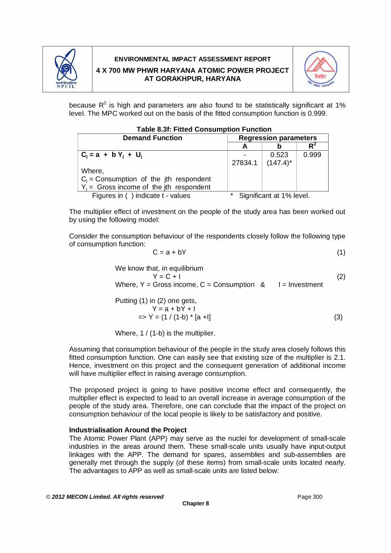
ENVIRONMENTAL IMPACT ASSESSMENT REPORT
4 X 700 MW PHWR HARYANA ATOMIC POWER PROJECT AT GORAKHPUR, HARYANA
© 2012 MECON Limited. All rights reserved Page 300
Chapter 8
because R2 is high and parameters are also found to be statistically significant at 1% level. The MPC worked out on the basis of the fitted consumption function is 0.999.
Table 8.3f: Fitted Consumption Function
Regression parameters Demand Function A b R2
Cj = a + b Yj + Uj Where, Cj = Consumption of the jth respondent Yj = Gross income of the jth respondent
-27834.1
0.523 (147.4)*
0.999
Figures in ( ) indicate t - values * Significant at 1% level.
The multiplier effect of investment on the people of the study area has been worked out by using the following model:
Consider the consumption behaviour of the respondents closely follow the following type of consumption function:
C = a + bY (1)
We know that, in equilibrium Y = C + I (2)
Where, Y = Gross income, C = Consumption & I = Investment
Putting (1) in (2) one gets, Y = a + bY + I => Y = (1 / (1-b) * [a +I] (3)
Where, 1 / (1-b) is the multiplier.
Assuming that consumption behaviour of the people in the study area closely follows this fitted consumption function. One can easily see that existing size of the multiplier is 2.1. Hence, investment on this project and the consequent generation of additional income will have multiplier effect in raising average consumption.
The proposed project is going to have positive income effect and consequently, the multiplier effect is expected to lead to an overall increase in average consumption of the people of the study area. Therefore, one can conclude that the impact of the project on consumption behaviour of the local people is likely to be satisfactory and positive.
Industrialisation Around the Project The Atomic Power Plant (APP) may serve as the nuclei for development of small-scale industries in the areas around them. These small-scale units usually have input-output linkages with the APP. The demand for spares, assemblies and sub-assemblies are generally met through the supply (of these items) from small-scale units located nearly. The advantages to APP as well as small-scale units are listed below:

ENVIRONMENTAL IMPACT ASSESSMENT REPORT
4 X 700 MW PHWR HARYANA ATOMIC POWER PROJECT AT GORAKHPUR, HARYANA
© 2012 MECON Limited. All rights reserved Page 301
Chapter 8
Advantages to the Proposed Plant Assurance of a reliable source of supply of spares and consumables; Supply on short-delivery schedules enabling maintenance of lower inventory; Saving foreign exchange through import substitution; Lower freight element in comparison to materials supplied by firm located far away; Better service facilities etc.
Advantages to Small Scale Units Availability of ready market; Getting price preference over distant suppliers; Availability of facilities from government; Availability of infrastructure support from the APP etc.
Proper utilisation of these mutual advantages is likely to play a catalytic role in the development of the region around the plant.
The small scale industries that are likely to come in the vicinity of the plant can be grouped into major two categories -- spares and chemical based, besides the service units. These are complemented by the service units. The present project is likely to accelerate such industrialization through “Bubble Effects” in the study area. It is important to note that the small scale units are usually labour-intensive and high-priority industries from social point of view.
The proposed project is expected to serve as centre of significant small-scale industrial economy around it complemented by the services sector. This is expected to play a major role in the future economic and social development of this area. Educational Status The project is expected to increase people’s thrust towards education by bringing opportunities of some direct & indirect employment for the local people. The general awareness towards the importance of education is expected to increase as a result of the new project and hence, it can be said that the project will have positive impact on the level of education of the people of the study area.
8.2.6 Peoples Perception The results of the opinion poll are analysed and furnished in Table 8.4. The major advantages and disadvantages shown by the people is given in Table 8.4. It is observed that 83% of them have identified creation of employment opportunity as the main advantage. People are hopeful of getting employment in the small-scale units likely to come up in the vicinity of the plant. About 33% of the respondents are expecting improvement in business. Around 58% of the respondents feel improvement in peripheral development activities. The major disadvantages shown by the people are radioactivity related threat to life in case of accidents as in other part of the world seems to be the cause of worry of the people. About 100% of the respondents are fearful about this aspect. Among other disadvantages, loss of land and house, about 83% are fearful about this

ENVIRONMENTAL IMPACT ASSESSMENT REPORT
4 X 700 MW PHWR HARYANA ATOMIC POWER PROJECT AT GORAKHPUR, HARYANA
© 2012 MECON Limited. All rights reserved Page 302
Chapter 8
aspect. About 75% of the respondents are showing concern to health due to environmental pollution.
Table 8.4: Peoples’ Perception on the Project
Perception No. of Respondents Distribution (%) ADVANTAGES Employment opportunity 20 83 Development of the area 14 58 Business development 8 33 DIS-ADVANTAGES Radioactive Damage in Case of Accidents 24 100 Pollution 18 75 Loss of land and house 20 83 Damage to health 10 42 Total Respondents 24
Major Advantage:
i. Present project may generate more employment, directly and indirectly, and major portion of it may be provided to the local people.
ii. Development of business opportunity in the area. iii. Development of infrastructure facilities including roads may take place due to the
project which may help in improving the whole area. iv. Improvement in living standard.
Major Disadvantage:
i. Accidents in the plant may cause radioactive releases which may be detrimental to life in the area as in some part of the world.
ii. Pollution in the study area is expected to rise due to the project. People perceive that the increase in pollution may cause damage to agriculture and damage to health of people due to pollution.
iii. Loss of agricultural land.
Needs of the Villagers and their Expectations It appears that the expectations and needs of the villagers are quite moderate. The people in the study require basic minimum amenities wherever they are not available and improving these facilities wherever these are inadequate. They appealed to the government through this survey, for provision and improving of the following facilities:
Proper compensation to the Project Affected Persons (PAP) of the Project Affected Villages
More Higher secondary schools Adult education centers Dispensaries / Health Centres and availability of doctors and other para-medical
staff Protected drinking water supply schemes

ENVIRONMENTAL IMPACT ASSESSMENT REPORT
4 X 700 MW PHWR HARYANA ATOMIC POWER PROJECT AT GORAKHPUR, HARYANA
© 2012 MECON Limited. All rights reserved Page 303
Chapter 8
Loan facility for self employment to open petty shops, purchase of cycle rickshaws, agricultural tools and implements, bullock carts, fertilizers, improved seeds and digging of well for irrigation.
8.2.7 Conclusions
On the basis of the overall results of the present impact assessment the following conclusions are drawn:
The project is not going to cause any damage to the existing agricultural situation. Instead, it is likely to provide the farmers with supplementary income.
The project has positive impact on pattern of demand The project has very strong positive employment and income effects. There is a possibility increase in industrialisation in the vicinity of the plant. This is
likely to bring more skill diversification among local people. The project has strong positive impact on raising average consumption and also
income through multiplier effect. The CSR activities of the project will have very strong positive impact on the social
and economic condition of the people of the study area The project has positive impact on health situation of the local people through
development of the area. The project has significant positive impact on community development activities of
the project which are likely to bring handful of benefits to the people of the study area.
Overall people’s perception on the project is not very encouraging However, they want implementation of a comprehensive Resettlement and Rehabilitation Action Plan (RAP)
8.2.8 Corporate Social Responsibility
Corporate Social Responsibility (CSR) is a form of corporate self-regulation integrated into a business model. CSR refers to strategies of corporations or firms to conduct their business in a way that is ethical, society friendly and beneficial to community in terms of development. CSR is the deliberate inclusion of public interest into corporate decision-making, and the honoring of a triple bottom line: People, Planet, Profit. Community Development (CD) refers to initiatives undertaken by community with partnership with external organizations or corporation to empower individuals and groups of people by providing these groups with the skills they need to effect change in their own communities. These skills are often concentrated around making use of local resources and building political power through the formation of large social groups working for a common agenda. The role of CSR in CD is any direct and indirect benefits received by the community as results of social commitment of corporations to the overall community and social system. The common roles of CSR in CD are as follows:

ENVIRONMENTAL IMPACT ASSESSMENT REPORT
4 X 700 MW PHWR HARYANA ATOMIC POWER PROJECT AT GORAKHPUR, HARYANA
© 2012 MECON Limited. All rights reserved Page 304
Chapter 8
To share the negative consequences as a result of industrialization. Closer ties between corporations and community. Helping to get local talents as an attractive employer for potential candidates.
Community development activities (including that for its employees) are very important aspects for any organization / project, because people of the villages surrounding the plant and its employees are the stakeholders. The project proponents have always treated its periphery as a key stakeholder. The main objective of the Community Development Programme has been to create synergy and synthesis with the environment. Guided and inspired by the objective of enhancing the living standards of the people. The policy of NPCIL towards social welfare & community development aims at strengthening the bond between the project / station authorities and the local population in the vicinity of nuclear power plants. In line with this policy, NPCIL at the existing nuclear power stations and projects has been carrying out number of community welfare activities in the following areas: Education – Gyan Gangothri Yojana Health– Arogya Sudha Yojana Infrastructure Community Welfare & Miscellaneous Accordingly NPCIL plans to implement above social and community welfare measures in area around the Gorakhpur Project with the following action plan. NPCIL would contribute in implementing social welfare activities in collaboration with
local Gram Panchayat, Block Development Office etc. for better development of area around the Project.
To minimize strain on existing infrastructure, adequate provision of basic amenities, viz. education, health, transport etc. would be made considering the needs of workforce and migrating population.
Sanitation facilities in construction labour colonies would be provided to ensure better hygiene and health.
Regular environmental awareness programs would be organized by NPCIL to impress upon the surrounding population about the beneficial impacts of the project and also about the measures being undertaken for environmental safety.
Welfare measures proposed to be implemented around HAPP, Gorakhpur Project Assistance in Educational Welfare Measures Assistance for Up-gradation of Schools facilities like classrooms, laboratories and
other associated requirements. Providing computers, sports item, laboratory equipment etc.

ENVIRONMENTAL IMPACT ASSESSMENT REPORT
4 X 700 MW PHWR HARYANA ATOMIC POWER PROJECT AT GORAKHPUR, HARYANA
© 2012 MECON Limited. All rights reserved Page 305
Chapter 8
Introduction of the talent nurture schemes for students from nearby villages by providing admission to AECS schools of NPCIL for free education or by providing suitable scholarships.
Assistance in Health-Care Welfare Measures Organization of the regular medical camps for chronic ailments prevailing amongst
the peoples of villages in and around JNPP. Proving consultancy and medicines as a part of preventive and promotive health
care. Hepatitis ‘B’ vaccination to school & village children.
Assistance in Community Welfare Measures Assistance in providing drinking water, street lighting, widening of roads,
strengthening of bridges etc. Assistance in construction of general community infrastructure facilities like
Panchayat Bhavan etc..
Assistance in Development of Farmers Welfare Measures Distribution of high quality seeds Assistance in upgrading farming facilities like cold storage etc. In the area around
Gorakhpur Project. Proposed Employees Development Efforts After commencement of the proposed project, a communication process will be initiated - orchestrated by the Station Director of the proposed plant. The Plant Management will interact with the employees periodically to identify the need of development and redressal of grievances of the employees (if any). Performance improvement workshops and Managements Communication Meetings will be the other interventions where the Project management will discuss with a cross section of employees the ways and means of bringing about improvements. The objective will be to inculcate a healthy work culture, which will aim at creating and sustaining a peaceful work environment where every employee can contribute to the plant in the assigned area of work, with full freedom and dignity and without fear. These human resource interventions will be based on a highly interactive style and will therefore facilitate a free flow of communication, increased awareness regarding the priorities of Atomic Power Plant and enhanced commitment among the employees by creating an ambience of trust and togetherness.


ENVIRONMENTAL IMPACT ASSESSMENT REPORT
4 X 700 MW PHWR HARYANA ATOMIC POWER PROJECT AT GORAKHPUR, HARYANA
© 2012 MECON Limited. All rights reserved Page 306
Chapter 9
CHAPTER 9 : ADDITIONAL STUDIES: RISK ASSESSMENT ON/OFF SITE EMERGENCY PLAN AND OCCUPATIONAL
HEALTH & SAFETY
9.00 ADDITIONAL STUDIES: RISK ASSESSMENT ON/OFF SITE EMERGENCY PLAN AND OCCUPATIONAL HEALTH & SAFETY
9.1 INTRODUCTION
Risk to the Atomic Power Plan (APP) and its surrounding may arise due the following factors: i. External natural events that are likely to affect plant safety and operation like
earthquakes, floods, extreme winds, land slides, soil liquefaction etc. ii. External man made events that are likely to affect plant safety and operation iii. Events within the plant due to hazardous chemicals used in the plant operation that
may affect the public and the environment. iv. Events within the plant due to radiological emissions that may affect the public and
the environment.
9.2 NATURAL EVENTS As discussed earlier in Chapter 2 under Section 2.4, a site evaluation study is a prerequisite before a site is approved for the construction of an atomic power facility like HAPP. The purpose of the study is by AERB to assess the engineer-ability of the plant at the selected site, in view of the effects of external natural events - like earthquakes, floods, extreme winds, land slides, soil liquefaction etc.
9.2.1 Earthquake Hazard The earthquake hazard map of part of northern India showing the project location is given in Fig. 9.1a. It can be seen that the project site falls under moderate damage risk zone. All precautionary measures have been considered while designing the engineering of the facility to meet any such events. The seismo-tectonic study conducted for the site as given under Section 4.5.6 (Chapter 4), revealed that the site is engineer-able from this consideration.
9.2.2 Flood Hazard The flood hazard map of part of northern India showing the project location is given in Fig. 9.1b. It can be seen that the project site is not falling under area liable to floods. However, the project site is within 10 km radius of “Fatehabad Branch of Bhakra Canal”. The canal is fully lined and hence there is very low probability of canal breach. Further all engineering precautionary measures have been considered while designing the facility to meet any such incidents.

ENVIRONMENTAL IMPACT ASSESSMENT REPORT
4 X 700 MW PHWR HARYANA ATOMIC POWER PROJECT AT GORAKHPUR, HARYANA
© 2012 MECON Limited. All rights reserved Page 307
Chapter 9
9.2.3 Cyclone Hazard The cyclone hazard map of part of northern India showing the project location is given in Fig. 9.1c. It can be seen that the project site falls under high damage risk zone, with wind velocity reaching up to 47m/s. All engineering precautionary measures have been considered while designing the facility to meet any such events.
9.2.4 Landslide Hazard The landslide hazard map of part of northern India showing the project location is given in Fig. 9.1d. It can be seen that the project site falls under zone which is unlikely to get any landslide events. However, all precautionary measures have been considered while designing the engineering of the facility to meet any such events.
Fig. 9.1a: Earthquake Hazard Map1 Showing Project Site
1 Seismic Zones of India Map IS:1893; 2002, Beuro of Indian Standards, Government of India.

ENVIRONMENTAL IMPACT ASSESSMENT REPORT
4 X 700 MW PHWR HARYANA ATOMIC POWER PROJECT AT GORAKHPUR, HARYANA
© 2012 MECON Limited. All rights reserved Page 308
Chapter 9
Fig. 9.1b : Flood Hazard Map2 Showing Project Site
2 Flood Atlas Task Force Report, Central Water Commission, Government of India
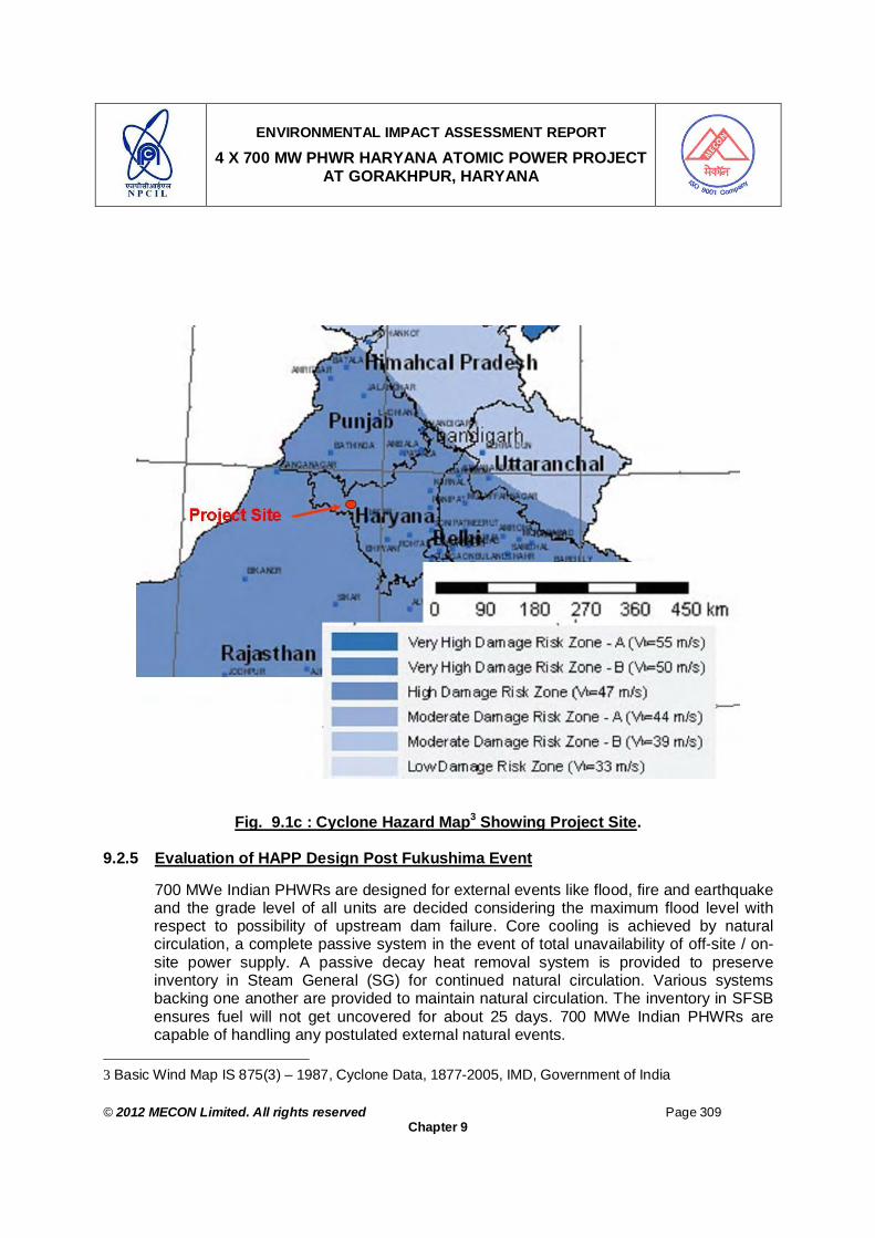
ENVIRONMENTAL IMPACT ASSESSMENT REPORT
4 X 700 MW PHWR HARYANA ATOMIC POWER PROJECT AT GORAKHPUR, HARYANA
© 2012 MECON Limited. All rights reserved Page 309
Chapter 9
Fig. 9.1c : Cyclone Hazard Map3 Showing Project Site.
9.2.5 Evaluation of HAPP Design Post Fukushima Event 700 MWe Indian PHWRs are designed for external events like flood, fire and earthquake and the grade level of all units are decided considering the maximum flood level with respect to possibility of upstream dam failure. Core cooling is achieved by natural circulation, a complete passive system in the event of total unavailability of off-site / on-site power supply. A passive decay heat removal system is provided to preserve inventory in Steam General (SG) for continued natural circulation. Various systems backing one another are provided to maintain natural circulation. The inventory in SFSB ensures fuel will not get uncovered for about 25 days. 700 MWe Indian PHWRs are capable of handling any postulated external natural events.
3 Basic Wind Map IS 875(3) – 1987, Cyclone Data, 1877-2005, IMD, Government of India

ENVIRONMENTAL IMPACT ASSESSMENT REPORT
4 X 700 MW PHWR HARYANA ATOMIC POWER PROJECT AT GORAKHPUR, HARYANA
© 2012 MECON Limited. All rights reserved Page 310
Chapter 9
Fig. 9.1d : Landslide Hazard Zone Map4 of India Showing Project Site
9.3 MAN MADE EVENTS
The risk of the external man induced events on the APP vis-à-vis the surroundings like chemical explosions occurring in the nearest public domain has been considered appropriate for analysis. A brief description of the postulated events and their impacts on the plant and surroundings are as follows.
9.3.1 Aircraft Crash Including Consequences of Impact, Fire and Explosion
AERB Safety Code specifies Screening Distance Values (SDV), for locating APP away from airports, landing and take-off zones, and air corridors, in order to limit the probability of such an event to less than 10-6 per year. An Air Port (small air port - not used for commercial flights) is located at Hisar, 33 km. SSE of the site. The Indira Gandhi International Air Port, Delhi is situated at about 208 km from the project site. Considering the current air traffic density and the projected growth in air traffic and the location of the site, a SDV of 8 km is required for an APP, and HAPP meets this requirement.
9.3.2 Effect of Accidents Taking Place Outside the Project Site
There are no major industrial facilities in the vicinity of proposed site. The only major industry “Thermal Power Plant at village Khedar (HPGCL)” is 20 km E of the project site. The nearest highway, NH10 is about 6.0 km away from the proposed site. The man made external events could result mainly from vehicles transporting hazardous
4 Disaster Management in India, Ministry of Home Affairs, Government of India 2011.

ENVIRONMENTAL IMPACT ASSESSMENT REPORT
4 X 700 MW PHWR HARYANA ATOMIC POWER PROJECT AT GORAKHPUR, HARYANA
© 2012 MECON Limited. All rights reserved Page 311
Chapter 9
chemicals like LPG, chlorine or ammonia, plying on the road. Traffic or other accidents may lead to large release of toxic chemicals or to chemical explosion. Three postulated events are considered below. Leakage of Chlorine: Consequence Analysis Chlorine is usually transported in horizontal tanks (usually referred to as tonner) constructed of mild steel with a capacity to store about 1000 kg. The typical dimensions of the tank are 0.785 m diameter and 2.1 m length. The storage is done at a pressure of about 10 kg/cm2 and at ambient temperature. The failure of the 9.5 mm spindle of the valve in the liquid phase and release of liquid chlorine into the atmosphere is taken as the maximum credible accident. A portion of the continuously releasing liquid chlorine would flash. The flashed chlorine would initially expand as a dense gas resulting in fatal concentrations. Subsequently it would disperse in the environment, greatly influenced by the prevailing atmospheric stability condition. Two types of parameters are estimated to provide a measure of the impact. One is the ‘Effect Distance’, which corresponds to the distance up to which lethal concentration (LC50) of vapor would be felt. Analysis indicated that the effect distance is approximately 480 m from the source under stable weather condition. For distances beyond 500 m, concentration profile was obtained using GPM, considering stability class F and wind speed as 2 m/s. The concentration of chlorine at a distance of about 2 km from the source is found to be about 20 ppm (60 mg/m3). Hence, event of this kind has no effect on safe operation of HAPP, which is about 6.0 km from the NH10. Leakage of Ammonia: Consequence Analysis A failure of the cylinder valve in the ammonia storage tank is postulated, leading to release of ammonia, initial flash and subsequent dispersion in the atmosphere. A continuous release and worst-case weather stability class (F, 2 m/s) have been considered for the dispersion. It has been observed that LC50 value of ammonia (6164 mg/m3) would be felt up to a distance of about 160 metres. This does not affect the safe operation of HAPP.
LPG Tanker Explosion The postulated incident considered is a catastrophic failure of an LPG tanker, taking place on the NH10. The effect of vapour build-up due to LPG tanker explosion is limited to a maximum of ~ 153 m, heat radiation effect on equipment is limited to ~ 114 m, overpressure effects are limited to ~ 175 m, and the structural damage is limited to ~ 146 m. The maximum damage distances are far less compared to the distance between HAPP and the highway.
9.3.3 Enemy Attack / Security Breach / Terrorist Activity
The nearest distance of site from the international border (Pakistan) is about 180km. There is little chance of enemy getting access to the facility. As regards security breach / terrorist activity in to the facility, sufficient security system has been adopted in the plant that there is no chance of the same.
ENVIRONMENTAL IMPACT ASSESSMENT REPORT
4 X 700 MW PHWR HARYANA ATOMIC POWER PROJECT AT GORAKHPUR, HARYANA
© 2012 MECON Limited. All rights reserved Page 312
Chapter 9
9.4 EVENTS WITHIN PLANT
For the purpose of risk assessment and onsite and offsite emergency plan related with the events within the plant, the risk due to non-radioactive substances and that due to radioactive materials are dealt separately. Accordingly next sections are elaborated.
9.4.1 Hazardous Chemicals
Industrial activities, which produce, treat, store and handle hazardous substances, have a high hazard potential endangering the safety of man and environment at work place and outside. Recognizing the need to control and minimize the risks posed by such activities, the Ministry of Environment & Forests have notified the “Manufacture Storage & Import of Hazardous Chemicals Rules ”in the year 1989 and subsequently modified, inserted and added different clauses in the said rule to make it more stringent. For effective implementation of the rule, Ministry of Environment & Forests has provided a set of guidelines. The guidelines, in addition to other aspects, set out the duties required to be performed by the occupier along with the procedure. The rule also lists out the industrial activities and chemicals, which are required to be considered as hazardous.
In the proposed project the power generation from atomic power (pressurized heavy water reactor (PHWRs)), is being planned. The major chemicals which will be stored by the project includes High Speed Diesel Oil (HSD). In view of the proposed activities are being scrutinized in line of the above referred “Manufacture, Storage and Import of Hazardous Chemical (Amendment) Rules, 1989 and its Amendment Rules 2000” and observations / findings are presented in this section. This plan covers mainly the HSD, which is going to be stored and subsequently handled during the plant operation. As per the Schedule I Schedule 1, paragraph (b) (iv) of “Manufacture, Storage and Import of Hazardous Chemical Rules, 1989, MOE&F” High Speed Diesel (HSD) falls under category “flammable liquids: chemicals which have a flash point lower than or equal to 600C but higher than 230C”.
The assessment has been made in a systematic manner covering the requirements of the above-mentioned rules.
Process Description The operation of the proposed project involves use of natural uranium oxide as fuel and heavy water (D2O) as coolant and moderator for the reactor. Refueling of the reactor will be carried out "on-power". The uranium dioxide (UO2) used for fuel is a ceramic with high melting point and chemically inert to water at operating conditions. So long as the ceramic fuel does not melt, the fission products remain entrapped in its matrix. During normal operation virtually all solid fission products are permanently retained in UO2 matrix and only a fraction of noble gases and volatile products diffuse into the inter space between fuel and cladding (for details see Chapter 2).

ENVIRONMENTAL IMPACT ASSESSMENT REPORT
4 X 700 MW PHWR HARYANA ATOMIC POWER PROJECT AT GORAKHPUR, HARYANA
© 2012 MECON Limited. All rights reserved Page 313
Chapter 9
For each unit of 700MWe there are 4 DG sets. Each DG is of capacity 4.2 MW with fuel consumption of 233g/KWhr (233g/KW/hr) or 979kg/hr. Each DG set will be provided with 114KL of capacity diesel Tank and with day tank of 8 hr duration of capacity 12 m3. Thus at a time maximum (114 m3 X 8 + 12 m3 X 16 = 2016 m3 or say) = 2100 m3 of HSD will be stored. One DG set is sufficient for supplying power to one 700MWe reactor. However, provision of 3 standby DG sets has been kept for emergency situation. One DG set is tested for ½ to 1.0 hour in a week. The other DG sets kept under standby are tested in subsequent weeks. Thus 4 DG set will run for maximum one hour during testing period for the four units of HAPP and during emergency situation 4 DG sets will run for 24 hours during emergency power failure situation. Applicability of the Rule From the above description of the process, it is observed that the chemicals stores / handled and involved are: (i) Bulk Storage of High Speed Diesel (HSD):
To decide whether the above mentioned industrial activities are likely to come within the scope of the above mentioned “Manufacture Storage and Import of Hazardous Chemicals Rules”, flow chart i.e. Fig. 9.2, pertaining to occupiers guide to the hazardous chemical regulation -1989 and the threshold quantities mentioned in the rules are used as given in Table 9.1a. Table 9.1a: Threshold Quantity and the Chemicals to be Stored and Handled
Threshold Quantities (Tonnes) SN Chemical Stored / Handled
Qty. Stored / Handled (In Tonne) And Storage / Handling Conditions
Whether Included in The List of Hazardous & Toxic Chemicals
For application of Rules 4,5,7 to 9 and 13 to 15
For application of Rules 10 to 12
1. High Speed Diesel 2100 m3 or 1890 t Yes 10.000 10,000 After comparison of the stored / handled and threshold quantities, it can be noticed that none of the stored / handled hazardous chemicals are more than the lower threshold quantity. However, for the other chemicals, the threshold quantities are not listed. Accordingly only rule 17 i.e. preparation and maintenance of material safety data sheets for these chemicals are required. The proposed project is going to utilise the HSD oil storage facility. The storage installation will conform to the requirement for such storages. All equipment will conform to the provision of statutory and other regulations of Government of India, including Indian Boiler Regulation and Tariff Advisory Committee and also provisions of National Fire Protection Association (NFPA) of USA.

ENVIRONMENTAL IMPACT ASSESSMENT REPORT
4 X 700 MW PHWR HARYANA ATOMIC POWER PROJECT AT GORAKHPUR, HARYANA
© 2012 MECON Limited. All rights reserved Page 314
Chapter 9
IS IT AN ACTIVITY WITHINTHE MEANING OF REG 2 NO ACTION
HAVE A HAZARDOUS CHEMICAL WITHINTHE MEANING OF REG 2
IS THE CHEMICAL LISTED IN SCHEDULE 3
DOES THE QTY EXCEED THE THRESHOLD QTY IN
SCH - 3 COL 4
IS THE HAZARDOUS CHEMICAL LISTED IN
SCHEDULE - 2
DOES THE QTY EXCEED THE THRESHOLD QTY IN
COL - 3 OF SCH - 3
YES
YES NO
NO
DOES THE HAZARDOUS CHEMICAL COME WITHIN THE CRITERIA OF PART-I AND/OR LISTED IN PART-II
OF SCH-1
DEMONSTRATE SAFEOPERATION AT ANY
TIME REG -4
NO ACTION
INFORMATION REGARDINGIMPORTS OF CONCERNEDAUTHORITY PREPARE &MAINTAIN MSDS & LABEL
(REG - 17 & 19)
IS THE ACTIVITY EITHERA USE SPECIFIED IN SCH-4
OR ISOLATED STORAGE
ACTION PREP ON SITE EMERGENCY PLAN (REG - 13);
PROVIDE INFORMATION TO LOCAL AUTHORITY FOR
DRAWING OFF SITE EMERGENCY PLAN (REG-14)
INFORM PUBLIC ABOUT MAZOR ACCIDENT HAZARD (REG-15)
IS THE QTY LARGE ENOUGH TO RENDER THE OPERATION CAPABLE OF
PRESENTING MAZOR ACCIDENT HAZARD
NOTIFY SITE OF ACTIVITY UPDATE SITE NOTIFICATION
(REG-7,8 & 9)
ACTION PREPARE & SUBMIT SAFETY REPORT PROVIDE
INFORMATION ON NOTIFICATION PROVIDE
FURTHER INFORMATION TO CONCERNED AUTHORITY
(REG - 10,11 & 12)
ACTION IN THE EVENT OF A MAJOR ACCIDENT REG-5 NOTIFY MAJOR
ACCIDENT PREPARE & SUBMIT A ON THE ACCIDENT TO CONCERNED
AUTHORITY SCHEDULE-5
YESDOES THE QTYEXCEED THE
THRESHOLD QTYIN SCH-2 COL-4
DOES THE QTYEXCEED
THRESHOLDQTY IN SCH - 2
COLUMN - 3
NO
YES
YES NO
YES
NO
NO
NO
NOYES
YES NO
NO
YES
YES
YES
Fig. No. 9.2: Occupiers Guide Description of Hazardous Chemicals The chemicals, which will be stored and handled, are presented in Table 9.1a. The Material Safety data sheets of all the above chemicals are presented below.
Material Safety Data Sheet : High Speed Diesel
1. Chemical Identity Chemical name: Diesel Oil Chemical classification: Flammable liquid Synonyms: Automotive Diesel Oil Trade name: HSD Formula Range: C13 - C18 C.A.S. NO.68476-30-2. U.N.NO. 1202 Regulated identification: Shipping name: HSD Codes/Label: Hazchem code class 3 Hazardous waste : N.A. Hazardous ingredients C.A.S.NO. Hazardous ingredients C.A.S.NO. Diesel 68476-30-2 Benzene Trace 71-43-2 Naphthalene Trace 91-20-3 Sulphur Trace 7704-34-9 Diesel is complex mixture of hydrocarbons .It’s exact composition depends on the source of crude oil from which it is produced and the refining methods used
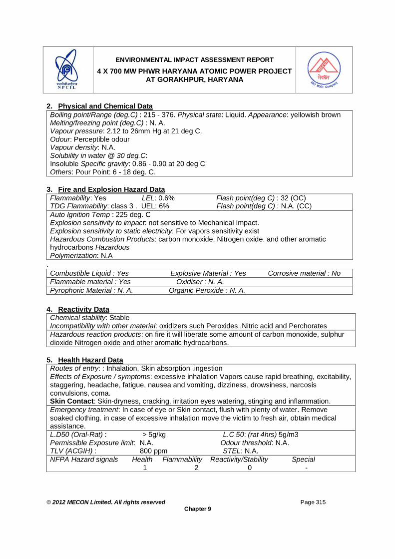
ENVIRONMENTAL IMPACT ASSESSMENT REPORT
4 X 700 MW PHWR HARYANA ATOMIC POWER PROJECT AT GORAKHPUR, HARYANA
© 2012 MECON Limited. All rights reserved Page 315
Chapter 9
2. Physical and Chemical Data Boiling point/Range (deg.C) : 215 - 376. Physical state: Liquid. Appearance: yellowish brown Melting/freezing point (deg.C) : N. A. Vapour pressure: 2.12 to 26mm Hg at 21 deg C. Odour: Perceptible odour Vapour density: N.A. Solubility in water @ 30 deg.C: Insoluble Specific gravity: 0.86 - 0.90 at 20 deg C Others: Pour Point: 6 - 18 deg. C.
3. Fire and Explosion Hazard Data Flammability: Yes LEL: 0.6% Flash point(deg C) : 32 (OC) TDG Flammability: class 3 . UEL: 6% Flash point(deg C) : N.A. (CC) Auto Ignition Temp : 225 deg. C Explosion sensitivity to impact: not sensitive to Mechanical Impact. Explosion sensitivity to static electricity: For vapors sensitivity exist Hazardous Combustion Products: carbon monoxide, Nitrogen oxide. and other aromatic hydrocarbons Hazardous Polymerization: N.A
. Combustible Liquid : Yes Explosive Material : Yes Corrosive material : No Flammable material : Yes Oxidiser : N. A. Pyrophoric Material : N. A. Organic Peroxide : N. A.
4. Reactivity Data Chemical stability: Stable Incompatibility with other material: oxidizers such Peroxides ,Nitric acid and Perchorates Hazardous reaction products: on fire it will liberate some amount of carbon monoxide, sulphur dioxide Nitrogen oxide and other aromatic hydrocarbons.
5. Health Hazard Data Routes of entry: : Inhalation, Skin absorption ,ingestion Effects of Exposure / symptoms: excessive inhalation Vapors cause rapid breathing, excitability, staggering, headache, fatigue, nausea and vomiting, dizziness, drowsiness, narcosis convulsions, coma. Skin Contact: Skin-dryness, cracking, irritation eyes watering, stinging and inflammation. Emergency treatment: In case of eye or Skin contact, flush with plenty of water. Remove soaked clothing. in case of excessive inhalation move the victim to fresh air, obtain medical assistance. L.D50 (Oral-Rat) : > 5g/kg L.C 50: (rat 4hrs) 5g/m3 Permissible Exposure limit: N.A. Odour threshold: N.A. TLV (ACGIH) : 800 ppm STEL: N.A. NFPA Hazard signals Health Flammability Reactivity/Stability Special 1 2 0 -

ENVIRONMENTAL IMPACT ASSESSMENT REPORT
4 X 700 MW PHWR HARYANA ATOMIC POWER PROJECT AT GORAKHPUR, HARYANA
© 2012 MECON Limited. All rights reserved Page 316
Chapter 9
6. Preventive Measures Personal Protective equipment: Canister type gas mask. PVC or Rubber. Goggles giving complete protection to eyes. Eye wash fountain with safety shower. Handling and storage precautions: Do not expose to heat and naked lights, keep containers and valves closed when not in use.
7. Emergency and First Aid Measures Fire: Fire Extinguishing Media: Foam, Carbon Di-oxide, Dry Chemical Powder. Water may be used to cool fire-exposed containers. Special Procedures: Shut off leak, if safe to do so, Keep non-involved people away from spill site. Eliminate all sources of ignition. Unusual Hazards: It will spread along ground and collect in sewers Exposure: Skin Contact: In case of contact with skin flush with fresh water, remove containment clothing. Inhalation: In case of excessive inhalation move the victim to fresh air, if problem in breathing give artificial respiration; give oxygen. Obtain medical assistance. Ingestion: Give water to conscious victim to drink. Do not induce vomiting Antidotes / Dosage : N.A. Spills: Steps to be taken to shutoff leak, if safe to do so, keep non-involved people away from spill site. Eliminate all sources of ignition. Prevent spill entering in to sewers, for Major spillage contact emergency services. Waste Disposal Method : N. A.
(i) Small Storage of Toxic Chemicals in Analysis Laboratory Apart from HSD no other hazardous chemical are stored in bulk quantity. However, there may be some toxic chemicals used in different laboratories of the plant, which will be used in analysis in the laboratory. But the quantity of the same will be very small. Preparation and maintenance of material safety data sheets for all such chemicals will be maintained at each laboratory as per the OSHAS 18000 requirements. The list of such chemicals is given in Table 9.1b. Table 9.1b: List of Toxic Chemicals Stored in Very Small Quantity in Laboratory
SN. Item Description 1 Acetic Acid Glacial 2 Acetone 3 Acetonitrile 4 Conc. Sulphuric Acid 5 Ammonia Solution 6 Ammonium Nitrate 7 Benzoyl Peroxide 8 Chromium Chloride Hexahydrate 9 Copper Chloride Crystal

ENVIRONMENTAL IMPACT ASSESSMENT REPORT
4 X 700 MW PHWR HARYANA ATOMIC POWER PROJECT AT GORAKHPUR, HARYANA
© 2012 MECON Limited. All rights reserved Page 317
Chapter 9
SN. Item Description 10 Copper Nitrate Trihydrate 11 Copper Sulphate Pentahydrate 12 Cyclo Hexamine 13 Dioxan 14 Hydrochloric Acid 15 Hydrogen Peroxide 16 Iodine Resublimed 17 Magnesium Metal Power 18 Morpholine 19 Nitric Acid 20 O- Tolodine reagent 21 Perchloric Acid 22 Pyridine 2,6-Dicarbocyclic Acid
9.4.2 Radiological Risk Assessment and Emergency Response System
There are two types of anticipated environmental impacts considered for nuclear power plants, especially with respect to radio-activity releases. The first ones are those which occur under normal operation of the plant and the second ones are those which can occur under accident conditions. The environmental factors that may be affected by the first type of environmental impacts during operation phase due to radio-activity releases are discussed in Chapter 5, under Section 5.5.2. The second type of impacts and mitigation measures are discussed here under.
9.4.2.1 Introduction & Design Philosophy
The Pressurized Heavy Water Reactors (PHWRs) proposed to be set up at Fatehabad have all the features of the modern technology, similar to western designs in respect of philosophy, features and construction. The design of plant is consistent with the standard international practices for safety systems. The basic concept of defense in depth in this plant includes the use of redundancy, diversity, independence and fails safe design. In fact, design features of the PHWR have been proposed to be set up as per International Atomic Energy Agency (IAEA). According to International Nuclear Safety Advisory Group, INSAG – 10 IAEA 1996 for pressurized heavy water cooled reactors at power operation, the barriers confining the fission products are typically the fuel matrix, the fuel cladding, the boundary of the reactor coolant system and the containment system. Accordingly, there are five levels of defense in depth with objectives as explained in Sections 2.11.1 to 2.11.4, Chapter 2.
9.4.2.2 Safety Objectives
The safety objective is to verify that the reactor and safety systems are properly designed and operated so that the occupational doses and dose to the members of

ENVIRONMENTAL IMPACT ASSESSMENT REPORT
4 X 700 MW PHWR HARYANA ATOMIC POWER PROJECT AT GORAKHPUR, HARYANA
© 2012 MECON Limited. All rights reserved Page 318
Chapter 9
public as a result of discharge of radioactive substances from the plant remain within the limits specified by AERB.
Safety Aspects All the radioactive sources in the plant which may lead to radioactive releases are identified and assessed for their hazard magnitude. However, the worst case scenario for any nuclear power plant is considered to be the damage of core where the fuel is loaded and a sustained chain reaction takes place in normal course of plant operation.
Accordingly, safety aspects are identified and evaluated by deterministic as well as by probabilistic assessment. Probabilistic safety assessment is seen as an extension of or complement to deterministic analyses. It systematically considers conceivable accident causes (Postulated Initiating Events (PIEs)) and for each initiating events, which can lead to core damage of different categories Core Damage Frequency (CDF) is calculated based on individual initiating events (IE) frequency. Through individual event sequence analysis for different IEs, it is estimated that the plant is provided adequate safety features and measures to mitigate or minimize any unsafe consequences.
As per AERB Safety Guide (SG-D-5), DBE (Design Basis Events) are categorized into four categories on the basis of their expected frequency of occurrence. Each of the DBE considered should be assigned to one of the following groups.
(1) Category-1 Events-Normal Operation, Operation transient and AOO (2) Category-2 Events-Events of moderate frequency (3) Category-3 Events-Events of low frequency (4) Category-4 Events-Multiple failures and rare events.
Events not falling in any of the above categories are called BDBE (Beyond Design Basis Events).
The concept of defense-in-depth is conveyed at all phases or activities related to ensuring the APP safety. Here, the strategy for preventing unfavorable plant damage state initiating events, especially for the 1st and 2nd level is of primary importance (details are provided in Section 2.11.1 to 2.11.4, Chapter 2).
In normal operating conditions, all of the physical barriers must be capable of functioning, whereas the measures on protecting them must be available. On detecting any problems in any of the barriers envisaged by the design or unavailability of measures for protecting it, the reactor plant must be shut down and measures for bringing the atomic power unit in a safe state must be taken.
The engineering measures and managerial, decisions meant for ensuring safety of APP must be proven by the previous experience or tests, studies or operating experience with prototypes. Such an approach should be applied not only when developing the equipment and designing the APP, but when manufacturing the equipment, constructing and operating the APP and upgrading its systems (components) as well.

ENVIRONMENTAL IMPACT ASSESSMENT REPORT
4 X 700 MW PHWR HARYANA ATOMIC POWER PROJECT AT GORAKHPUR, HARYANA
© 2012 MECON Limited. All rights reserved Page 319
Chapter 9
The values of overall Core Damage Frequency (CDF) will be within the design target of 1.0 E-6 /reactor-year for the reactor proposed to be set up at Fatehabad, which is below acceptable limit of 1.0 E-5 /reactor-year, as per International Atomic Energy Agency (IAEA) Safety Series No. 75 – INSAG-3, 1988.
Multi Barriers of Safety The safety of the NPP is ensured by incorporating many barriers between the source and the receptor. Protection implies a system of physical barriers on the way by which the ionizing radiation and radioactive substances can release into the environment. This system is used together with a complex of engineering and managerial measures for protecting these barriers and maintaining their effectiveness and measures for protecting the personnel, population and the environment.
The system of physical barriers of the NPP power unit incorporates: a fuel element, fuel element cladding, the pressure boundary of the reactor coolant and the containment. An exclusion zone also provides a dilution of radioactivity before it is reaches to the public domain.
9.4.2.3 Radiological Objectives
The general principle applied is that, for the transients, incidents and accidents considered in the design (Table 9.2), the more frequent the event, the lower the radiological consequences.
The normal operating and transient conditions must not result in normal operating limits being exceeded. These operating conditions and transients are covered by the overall dose limit of 1.0 mSv /yr to the members of public at 1.0 km from the reactor i.e. the fence post of the exclusion zone.
The radiological objectives associated with other conditions viz. accidents (Table 9.2) to meet the appropriate reference dose limits under these conditions. For the above referred conditions, the maximum thyroid and whole body doses from APP at a distance of 1.0 km would be kept well within the reference doses of 500 mSv to child thyroid and 100 mSv to an adult whole body as stipulated by AERB.
Radiological Aspects The radiological consequences to the public can be broadly divided into two categories i.e. during normal operation and during accident condition. During normal operations, the controlled release of radioactive materials is governed by the Effective Dose Limits (EDL), applicable to the members of public. EDL as stipulated by AERB is 1 mSv/year. There are mainly two routes of exposures i.e. air route and aquatic route. In accident conditions, the consequence depends on the accident scenario.
While siting atomic power plants, three areas are defined as exclusion zone, sterilized zone and monitoring zone. Exclusion zone extends up to 1.0 kms, which will be under the exclusive control of the power station where no public habitation is allowed. The sterilized zone is the annulus between 1.0 kms and 5 kms radius from the reactors where natural growth is permitted but new expansion of activities which lead to enhance
ENVIRONMENTAL IMPACT ASSESSMENT REPORT
4 X 700 MW PHWR HARYANA ATOMIC POWER PROJECT AT GORAKHPUR, HARYANA
© 2012 MECON Limited. All rights reserved Page 320
Chapter 9
population growth are regulated. The area from project to site 30 kms zone is the monitoring zone. The areas under plant zone, exclusion zone and sterilized zone for the HAPP Project are shown in Fig. 9.4.
For, Fatehabad Site, the methodology for calculation of doses during off normal situations will be as per AERB safety guide (AERB/SG/S-5D-21). The doses will be worked out by using the two types of dose conversion factors. For initial two hrs into the accident, the site-specific worst meteorological parameters are assumed to maximize the dose. For subsequent releases, time averaged dispersion parameters are used. The worst affected sector will be taken with no change in wind direction.
The maximum thyroid and whole body doses from APP under abnormal situations at a distance of 1.0 km will be kept well within the reference doses of 500 mSv and 100 mSv as stipulated by AERB for child thyroid and whole body respectively.
Radiation Protection Considerations ALARA Policy The radiation protection policy taken into account for design is to ensure that the individual dose of site personnel and members of the public does not exceed the dose limits set by the regulatory agency and is kept at a level As Low As Reasonably Achievable (ALARA) and as per the requirements of AERB. The details are presented as in Section 2.15.4, Chapter 2. This policy is embodied in the design, construction, operation, maintenance, in-service inspection, refueling, and non-routine activities.
General Design Considerations General design considerations and methods employed to maintain in Plant occupational radiation exposures, in line with ALARA have two objectives: to minimize the amount of personnel time spent in radiation areas, to minimize radiation levels in routinely occupied Plant areas and in the vicinity of
Plant equipment expected to require personnel attention.
Equipment and facility design are considered in maintaining occupational radiation exposures ALARA during plant operations including: normal operation, maintenance and repairs, refueling operations and fuel storage, in-service inspection and calibrations, radioactive waste handling and disposal, and other anticipated operational occurrences. General equipment design considerations to minimize the amount of personnel time spent in a radiation area include: Reliability, durability, construction, and design features of equipment, components,
and materials to reduce or eliminate the need for repair or preventive maintenance. Service convenience for anticipated maintenance or potential repair, including ease
of disassembly and modularization of components for replacement or removal to a lower radiation area for repair.

ENVIRONMENTAL IMPACT ASSESSMENT REPORT
4 X 700 MW PHWR HARYANA ATOMIC POWER PROJECT AT GORAKHPUR, HARYANA
© 2012 MECON Limited. All rights reserved Page 321
Chapter 9
Redundancy of equipment or components to reduce the need for immediate repair when radiation levels may be high, and when no feasible method is available to reduce radiation levels,
Provisions, where practicable, to remotely or mechanically operate, repair, service, monitor, or inspect equipment.
General facility layout design considerations to minimize the amount of personnel time spent in a radiation area include: locating equipment, instruments, and sampling stations which will require routine
maintenance, calibration, operation, or inspection, for ease of access and minimum required occupancy time in radiation areas,
laying out Plant areas to allow remote or mechanical operation, service, monitoring, or inspection of highly radioactive equipment,
providing, where practicable, for transportation of equipment or components requiring service to a lower radiation area.
General facility layout design considerations directed towards minimizing radiation levels in Plant access areas and in the vicinity of equipment requiring personnel attention, include: separating radiation sources and occupied areas, where practicable (e.g., pipes or
ducts containing potentially highly radioactive fluids, do not pass through occupied areas),
providing adequate shielding between radiation sources, and access and service areas,
where appropriate, separating equipment or components in service areas with permanent shielding,
locating equipment, instruments and sampling sites in the lowest practicable radiation zone,
providing means and adequate space for utilizing movable shielding for sources within the service area, when required,
providing means for decontamination of service areas, providing means to control radioactive contamination and to facilitate
decontamination of potentially contaminated areas.
Average Environmental Radiation Dose to the Members of Public Out Side of Exclusion Zone for Operating APP’s in India As per the reports from Environmental Survey Laboratory (ESL), BARC, the average environmental radiation dose (micro Sievert per year) at 1.6 Km radius due to operation of Nuclear Power Plants in India 2006-2010 is given in the Fig. 9.3. The present AERB public domain dose limit is 1000 micro Sievert/year. It may be seen that the public domain dose values in case of TAPS, RAPS and MAPS have been reported to be mostly below 50 micro Sievert / year (20 times lesser than stipulated standard). In the case of NAPS, KAPS and Kaiga, these value are in the range of 1.7 to 2.8 micro Sievert / year. This is also to mention that these values are excluding background natural radiation average dose of 2400 micro Sievert / year and medical exposures. This indicates that the exposure of public to the radiation is far below the stipulated limit in all the nuclear power plants in India.
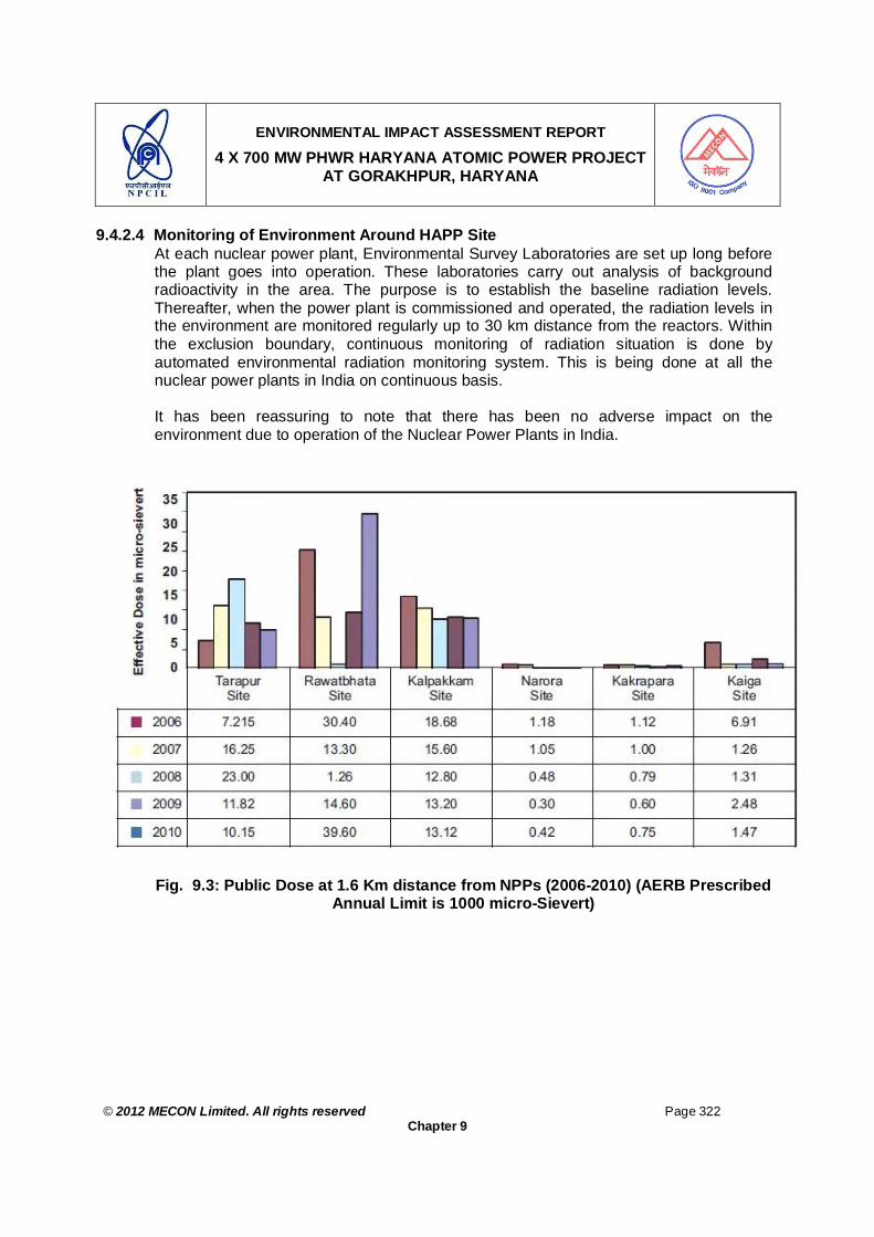
ENVIRONMENTAL IMPACT ASSESSMENT REPORT
4 X 700 MW PHWR HARYANA ATOMIC POWER PROJECT AT GORAKHPUR, HARYANA
© 2012 MECON Limited. All rights reserved Page 322
Chapter 9
9.4.2.4 Monitoring of Environment Around HAPP Site At each nuclear power plant, Environmental Survey Laboratories are set up long before the plant goes into operation. These laboratories carry out analysis of background radioactivity in the area. The purpose is to establish the baseline radiation levels. Thereafter, when the power plant is commissioned and operated, the radiation levels in the environment are monitored regularly up to 30 km distance from the reactors. Within the exclusion boundary, continuous monitoring of radiation situation is done by automated environmental radiation monitoring system. This is being done at all the nuclear power plants in India on continuous basis. It has been reassuring to note that there has been no adverse impact on the
environment due to operation of the Nuclear Power Plants in India.
Fig. 9.3: Public Dose at 1.6 Km distance from NPPs (2006-2010) (AERB Prescribed Annual Limit is 1000 micro-Sievert)

ENVIRONMENTAL IMPACT ASSESSMENT REPORT
4 X 700 MW PHWR HARYANA ATOMIC POWER PROJECT AT GORAKHPUR, HARYANA
© 2012 MECON Limited. All rights reserved Page 323
Chapter 9
Environmental Survey Laboratory An Environmental Survey Laboratory (ESL) will be set up for regular monitoring of environmental parameters throughout the operation of the plant. The primary aim of the environment monitoring program is to assess the radiation exposure of public residing around Fatehabad site and to demonstrate that radiation exposure received by the member of the public is within the limit prescribed by the regulatory agency based on international guidelines
Objectives of Environmental Monitoring To generate environmental radiological database. To assess the possible dose commitments to the population due to operation of the
nuclear power station. To determine control action during site / off site emergencies.
This requires detailed measurements on a number of environmental matrices for radioactivity content that may result from the release of radioactivity effluents during the normal operation of the nuclear facilities.
Pre-operational survey Operational Survey
External Radiation Radioactivity concentration in air & water. Strontium, Cesium and Iodine activity in environmental matrices.
Type of Sample Number of Typical Samples Analyzed in a Year Environmental Survey Laboratories (ESL) are located at each of the nuclear power project sites in the country. These ESLs are operated by an independent organization viz. Health Physics Division of Bhabha Atomic Research Centre. At the existing NPPs, ESLs have been collecting samples in the radius of 30 km from the plant site and their reports conclude that the dose to population at the fence resulting from the existing NPPs in the country is about 1.5% of the authorized dose limit, which is a small fraction of the natural background radiation. The doses at further distances are still lower.
SN. Type of samples Number of Typical Samples
Analysed per Year 1 Surface water 500 2 Drinking water 200 3 Well water 400 4 Air Samples for tritium 500 5 Air samples for particulates 50 6 Goat Thyroid 50 7 Vegetables, milk, pulses, cereals, meat, eggs, fish, etc. 70 8 Weed, silt, soil, sediments, grass, leaves, etc. 40
9.5 ON/OFF SITE EMERGENCY PLAN / EMERGENCY RESPONSE SYSTEM
The purpose of planning for on-site/off-site radiation emergency response is to ensure adequate preparedness for protection of the plant personnel and members of the public

ENVIRONMENTAL IMPACT ASSESSMENT REPORT
4 X 700 MW PHWR HARYANA ATOMIC POWER PROJECT AT GORAKHPUR, HARYANA
© 2012 MECON Limited. All rights reserved Page 324
Chapter 9
from significant radiation exposures in the unlikely event of a severe accident. The probability of a major accident resulting in the releases of large quantities of radioactivity is extremely small. The probability, however, can never be reduced to absolute zero and therefore this residual risk is sought to be mitigated by appropriate siting criteria and implementing suitable arrangements for emergency planning and preparedness.
As stipulated in AERB Safety Guide No. SG/HS-1, to limit the radiological consequences in public domain, the whole area around NPPs is divided into three domains based on severity of prevailing radiation fields subsequent to the accidental release of radioactivity. Appropriate intervention levels and derived intervention levels are assigned in advance for each domain so that off-site emergency countermeasures could be implemented in a pre-planned manner. Following countermeasures have been found suitable to deal with radiological emergency in the public domain.
Iodine Prophylaxis administration Sheltering Evacuation Decontamination Control of food and water supplies Use of stored animal feed Decontamination of area
The selection of one or more of the above protective measures is based on the nature of the accident and its associated risk and in particular, time factor associated with these two factors.
The intervention levels as stipulated in AERB Safety Guide No. SG/HS-1 for protective measures are implemented at very low radiation levels, compared to radiation levels which cause serious injurious to persons receiving acute whole-body radiation exposure.
The requirements of emergency counter-measures in case of various DBE are assessed. Emergency counter-measures like distribution of iodine prophylaxis and sheltering would be needed based on intervention level.
The agencies responsible for carrying out remedial measures during the different categories of emergencies mentioned above are as follows:
Type of Emergency Responsible Agency Emergency Standby Personnel Emergency Plant Emergency Site Emergency
Plant / Site Management
Off-site Emergency District authorities of the State Government having jurisdiction over the public domain affected by the accident, normally the District Collector.

ENVIRONMENTAL IMPACT ASSESSMENT REPORT
4 X 700 MW PHWR HARYANA ATOMIC POWER PROJECT AT GORAKHPUR, HARYANA
© 2012 MECON Limited. All rights reserved Page 325
Chapter 9
9.5.1 Emergency Standby Emergency standby is defined as abnormal plant conditions with potential to develop into accident situations, if timely preventive actions are not taken. During this situation pre-identified plant personnel are placed in a state of alert for implementing the emergency response procedure.
9.5.2 Personnel Emergency
When the radiological consequences of an abnormal situation are confined to some personnel working in a plant, without affecting the plant, it is described as a personnel emergency. For example, some of the plant personnel may be working at a location within the reactor building where the radiation field is significantly above prescribed limits for extended period resulting in their excessive radiation exposure. Some other examples of personnel emergency are given below:
o splashing of radioactive material on personnel while carrying out o operation/maintenance in such a manner that excessive contamination, o internal and/or external, has occurred or is suspected; o high uptake of radioactive material has inadvertently occurred or is suspected; o personnel contamination at levels exceeding prescribed limits; o high external exposures has occurred or is indicated; o the person is physically ill or incapacitated; o exposed to a heavy chlorine dose in a chlorine plant.
9.5.3 Plant Emergency When the radiological consequences of an abnormal situation are expected to remain confined to the plant, it is described as a plant emergency. This situation may arise during operation or shutdown maintenance of the reactor.
9.5.4 Site Emergency
An accidental release of radioactivity extending beyond the plant but confined to the site boundary (exclusion zone) constitutes a site emergency. An assessment of such a situation would imply that protective measures are limited to the exclusion zone. Site Emergency is declared and terminated by Site Emergency Director (SED). The protective measures in a Site emergency include evacuation from the affected parts of the site and also radiological monitoring of the environment in the Emergency Planning Zone (EPZ). The emergency reference level for on-site emergency is given below.
9.5.5 Off Site Emergency
An off-site emergency occurs when the radiological consequences of an emergency situation originating from APP are likely to extend beyond the site boundary (exclusion zone) and into the public domain. For the purpose of planning off-site emergency, an emergency-planning zone (EPZ) up to 16km radius is specified. There should be fixed criteria to determine an off-site emergency in terms of the release of radioactivity as indicated by the radiation monitoring system.

ENVIRONMENTAL IMPACT ASSESSMENT REPORT
4 X 700 MW PHWR HARYANA ATOMIC POWER PROJECT AT GORAKHPUR, HARYANA
© 2012 MECON Limited. All rights reserved Page 326
Chapter 9
The protective measures in public domain shall be implemented by the District Officials under the supervision of the district collector or the divisional Commissioner, who shall be designated as the Off-site Emergency Director (OED).
The manual on Off-site Emergency Response Plans would be issued by the State Level Emergency Response Committee. The manual shall specify the need of radiation impact assessment based on immediate, intermediate and long-term consequences according to space-time domain concept and the necessary intervention measures such as evaluation, sheltering and food control. Off-site emergency shall be declared and terminated by OED on the basis of technical assessment made by SED.
The Station Director HAPP is identified as the Plant Emergency Director (PED) and all the Superintendent and Health Physicist are the members of the plant Emergency Committees.
Consequent to the declaration of the site emergency the Station Director of HAPP handover the charge of Plant emergency director (PED) to Chief Superintendent and assumes the charge of Site Emergency Director (SED). The PED provides all plant related information to the SED and works as per the advice of the SED to mitigate the situation in the plant.
The SED is the Chairman of the Site Emergency Committee (SEC) and is responsible for convening the SEC, when the 1st report of the initiation of an emergency is received by SED. SED shall obtain technical inputs, such as particulars of the accident, from the members of the SEC. The decisions for declaration/termination of an emergency shall be based on inputs so obtained. The Site Emergency Organisation structure & the recommended plant emergency response action flow diagram are chalked out.
Consequent to the declaration of the Off-site emergency For HAPP, the District Collector, Fatehabad will be the Off-site Emergency Director (OED). Its membership includes the chiefs of all public services relevant to the emergency management in the district and the Station Director of HAPP. The OED shall be the Chairman of the Off-site Emergency Committee (OEC) and is responsible for convening OEC when the report of the initiation of an emergency is received by OED. The Action Flow Diagram for the site/off-site emergencies and Information Flow Diagram for site/off-site emergencies have been chalked out. The Shift Charge Engineer (SCE) on duty is among the first to learn about the occurrence of an off-normal situation. He shall evaluate the condition and the data on the basis of which an emergency may be declared / terminated. He shall notify SED about any condition which may warrant the declaration of an emergency.
9.5.6 Exercises
Emergency scenarios shall be developed to test emergency plans and operational response at all levels. Exercises and drills shall be conducted once in a quarter for Plant Emergency to see that the staffs are adequately trained and all the emergency
ENVIRONMENTAL IMPACT ASSESSMENT REPORT
4 X 700 MW PHWR HARYANA ATOMIC POWER PROJECT AT GORAKHPUR, HARYANA
© 2012 MECON Limited. All rights reserved Page 327
Chapter 9
equipment are kept in good conditions. At the end of each exercise/drill an evaluation of the response call shall be carried out to take care of any deficiency noticed. Site emergency exercise is carried out once in a year. Off-site Emergency exercise is carried out once in two years.
Emergency plan shall be reviewed at least once in five years, the improvements and updating procedures shall be implemented based on feed back and critiques from exercises. Periodic exercises are conducted as per stipulation of AERB with the active participation of relevant state and public authorities. These exercises are witnessed by observers from Crisis Management Group (CMG), DAE, AERB, BARC and NPCIL-HQ.
Feed back is a very valuable aspect of the exercise of offsite emergency and authorities will resolve the deficiencies surfaced out and action plan will be chalked out depending upon the requirements.
The approved plan for HAPP will be ready before criticality of HAPP.
The nature and magnitude of response measures would depend on the specific category or extent of emergency. Though safety evaluation of an APP relates to design basis, the HAPP emergency response plan shall be based not only on design basis events but also on accident conditions due to more severe events, even if they have a very low probability of occurrence. An analysis of such events and the projected radiological consequences specific to the APP shall form the basis of response plan, so that the nature and magnitude of response actions could be established.
9.5.7 Emergency Preparedness System for HAPP
The documented emergency planning and preparedness program to be established and practiced for HAPP will be approved by AERB. This documented manual on emergency preparedness and response for HAPP will be in two volumes as follows:
Volume-I : Plant/Site Emergency Procedure. Volume-II : Procedure for Off-Site Emergency.
The salient features of the emergency preparedness system for HAPP are elaborated in the following sections.
9.5.8 Volume I : Plant / Site Emergency Procedure
Emergency Organization and Responsibility To effectively manage the emergency situation at HAPP, Fatehabad site Emergency Committee (JEC) consisting of Advisory Group, Service Group, Damage Control Group and Rescue Team will be established. The details of Fatehabad Emergency action flow diagram for site / off site emergencies is presented in Fig. 9.4.

ENVIRONMENTAL IMPACT ASSESSMENT REPORT
4 X 700 MW PHWR HARYANA ATOMIC POWER PROJECT AT GORAKHPUR, HARYANA
© 2012 MECON Limited. All rights reserved Page 328
Chapter 9
Communication The responsibility of communication during emergency lies with Communication Group. This group ensures that all communication equipment is kept functional at all time. It consists of Engineer-in -charge of the Plant, communication system, Telephone operators and wireless operator.
Resources and Facilities Main Control Room conference room will be made into Plant Emergency Control Centre (PECC) and Station Director’s Office will be converted in to Site Emergency Control Centre. These centers will be provided with communication facility within the HAPP site and outside agency. The plant emergency equipment centre will be located at Administrative building or any suitable location and it will be augmented with ready to use equipment for the plant /site emergency. Normally Zone-II and Zone III area shower and wash room are to be used for emergency personnel decontamination purpose. However there will be a separate facility for casualty at Residential complex hospital when it is commissioned. A special emergency service vehicle fitted with two –way radio equipment and necessary monitoring & survey equipment will be available at all time under control of on duty Shift Charge-Engineer (SCE). Different assembly areas for different working groups will be identified inside the operating area or plant fencing and maintained for assembly in the event of an emergency. Emergency shelter locations will be identified for sheltering /evacuation due to emergency condition and the plant personnel shall proceed to the shelter areas in the event of an emergency.
Action plan for responding to Emergency After hearing the emergency siren and announcement about emergency situation and or getting information of the same through telephone, all responsible members of the JEC shall proceed to Main control room/ PECC. Details of handling plant /on-site emergency situations will be documented and made available at PECC. The action flow diagram for on site and off site emergencies is given in Fig. 9.4.
9.5.9 Volume II : Procedure for Off-Site Emergency
This volume will provide guidelines for handling off-site emergency at HAPP and deals with emergency management organization, emergency equipment and facilities for handling the situation up to 16 km radius.
Emergency Planning Zones and Sectors The area around the plant site is divided into various zones and sectors as described below for effective handling of the emergency situations:
In normal operation of the proposed PHWR category atomic power plant, the impact zone would not be beyond 1.0 km, which would also hold good for off normal situations due to advanced technological features in built in the design of the reactor. However, on a conservative side, an area of 16 km around the plant is considered as emergency planning zone as per the requirements of AERB as described below:

ENVIRONMENTAL IMPACT ASSESSMENT REPORT
4 X 700 MW PHWR HARYANA ATOMIC POWER PROJECT AT GORAKHPUR, HARYANA
© 2012 MECON Limited. All rights reserved Page 329
Chapter 9
As per AERB requirements, the exclusion zone covers a distance of about 1.0 km around the plant site within which no habitation is permitted and is protected by security personal from state /central government agency/Central Industrial Security Force (CISF). The sterilized zone covers a distance from exclusion boundary at 1.0 km to 5 km radius around the plant site within which natural growth of population is permitted and unrestricted growth of population and development are controlled by state administration through administrative measures. The zone of 0 -16 km is termed as emergency planning zone (EPZ) and is divided in to 16 sectors marked as A to P in clockwise direction .
9.5.10 Frequency /Periodicity of Emergency Exercises
Plant emergency Exercise – Quarterly Site emergency Exercise – Yearly Off-Site emergency Exercise – Two Yearly
9.5.11 Habitability of Control Rooms under Accident Conditions
The habitability of control rooms under accident conditions is ensured as indicated below: The habitability systems of the main control room (MCR) and supplementary control room (SCR) incorporate systems and equipment, protecting the operators from radioactive, toxic and harmful gases, aerosols and smoke, for creating safe normal habitability conditions permitting the operators to control the power unit and also to maintain it in a safe state even under emergency modes, including accidents involving the primary circuit loss of coolant.
Mode I – Normal Operating Conditions In the normal mode, supply of outdoor air cleaned from dust is provided. Duration of mode I is not restricted. The air entering from outside is mixed with recirculation air, is cleaned on coarse and fine filters, cooled in the air cooler and by the fan along air ducts network is supplied to the room via fire-retarding ducts. The air from the rooms is withdrawn by exhaust fans and is supplied to the suction of the air conditioning systems and to plenum vent center. The difference between the amount of the plenum and recirculation air creates the required air head in the MCR rooms.
Mode II – Filtering/Ventilation Mode The operation mode II is introduced automatically by indications of the radiation monitoring transducers on rise of radioactivity in the intake air more than ≥3.10-7 Gy/h, corresponding value of volume activity of iodine radio-nuclides 3.10 +2 Bq/m3. Mode II duration is not less than 10 hr -period required for bringing the unit to cool down state. The outdoor air flow rate is determined by the necessity to create a head in the MCR air-tight area, as well as providing of the personnel with the outdoor air meeting the sanitary (public health) standards (60 m3 per human being).

ENVIRONMENTAL IMPACT ASSESSMENT REPORT
4 X 700 MW PHWR HARYANA ATOMIC POWER PROJECT AT GORAKHPUR, HARYANA
© 2012 MECON Limited. All rights reserved Page 330
Chapter 9
Outdoor air, now passes via filters, is cleaned, and supplied to suction of the air conditioning system. The air conditioning system continues functioning as in mode I.
Mode III – Mode of Total Isolation of the MCR Rooms This mode is introduced during emergencies for a period permitting the external services of radiometric and chemical control to determine the content and concentration of toxic substances in the atmospheric air in the MCR conditioners air intake area.
Besides, mode III shall be introduced in case of the outdoor air contamination by toxic substances, carbon monoxide (in case of fire) and other harmful substances not retained by the absorbing filters. In mode III air-tight valves in the outdoor line close, the operator opens manually a valve on compressed air pipeline. On loss of power supply to the system the operator manually opens a valve on compressed air pipeline. The conditioning system continues operating for full recirculation.
To maintain the required pressure in the MCR rooms, compressed air from cylinders is used. The mode duration is assumed to be 4h, without replenishment. With replenishment, the occupancy for indefinite period is possible. Storage location on the cylinders is decided considering this aspect.
By signals of external surveillance services the operator takes decision about the necessary mode of ventilation (I, II, III).

ENVIRONMENTAL IMPACT ASSESSMENT REPORT
4 X 700 MW PHWR HARYANA ATOMIC POWER PROJECT AT GORAKHPUR, HARYANA
© 2012 MECON Limited. All rights reserved Page 331
Chapter 9
Fig. 9.4 : Action Flow Diagram for Site / Off Site Emergencies

ENVIRONMENTAL IMPACT ASSESSMENT REPORT
4 X 700 MW PHWR HARYANA ATOMIC POWER PROJECT AT GORAKHPUR, HARYANA
© 2012 MECON Limited. All rights reserved Page 332
Chapter 9
Table 9.2: Radiological Emergency and Risk to Public
SN. Risk Categories Affected Zone Classification of Emergency/ agency for handling it
Risk to Public
1 Normal operation Nil Nil Nil 2 Operational
deviations Nil Nil Nil
3 Natural or any man made incidents/ accidents without release of radioactivity
Localized area inside the plant
Plant Emergency/ Plant management as per existing preparedness procedure
Nil
4 Hypothetical Incidents or accidents that causes impact within operating area or plant boundary
Plant Emergency/ Plant management as per existing preparedness procedure
Nil
5
Natural or any man made incidents/ accidents which are DBA causing release of radioactivity
Hypothetical Incidents or accidents that causes impact with in Plant boundary and within 1.6 km radius (Exclusion Zone)
On-Site Emergency/ Site/Plant management as per existing emergency preparedness procedure for on-site
Nil
6 Natural or any man made incidents/ accidents, which are beyond DBA causing release of radioactivity to environment.
Hypothetical Incidents or accidents that causes impact beyond 1.6 km radius (Exclusion Zone)
Off-Site Emergency/ off-Site emergency preparedness procedure/manual
Countermeasures are implemented to mitigate the consequences.
9.6 OCCUPATIONAL HEALTH AND SAFETY PLAN
In the proposed APP multifarious activities will be involved during construction, erection, testing, commissioning, operation and maintenance, the men, materials and machines are the basic input. Industrialization generally brings several problems like occupational health and safety. The industrial planner, therefore, has to properly plan and take the steps to minimize the impacts of industrialization and to ensure appropriate occupational health, safety including fire plans. All these activities again may be classified under construction and erection and operation and maintenance. The proposed plan is given hereunder.
ENVIRONMENTAL IMPACT ASSESSMENT REPORT
4 X 700 MW PHWR HARYANA ATOMIC POWER PROJECT AT GORAKHPUR, HARYANA
© 2012 MECON Limited. All rights reserved Page 333
Chapter 9
9.6.1 Corporate Environment OHS Policy Occupational Health and Safety of employees will be the prime concern of the project proponent. The project proponents will be dedicated to implement Safety, Health and Environment policy and will strive to make OHS as a part of the industrial life. A copy of Corporate Environment Policy of NPCIL is presented as Annexure IVE.
9.6.2 Occupational Health
Occupational health needs attention both during construction and erection and operation and maintenance phases. However, the problem varies both in magnitude and variety in the above phases. Full fledge hospital facilities will be made available round the clock for attending emergency arising out of accidents, if any. Construction and Erection Phase The occupational health problems envisaged at this stage can mainly be due to constructional accident and noise. To overcome these hazards, in addition to arrangements to reduce it within the threshold limit value (TLV’s), personal protective equipment’s will be supplied to workers. Operation and Maintenance Phase The problem of occupational health, in the operation and maintenance phase is due to noise hearing losses. Suitable personnel protective equipment will be given to employees.
9.6.3 Occupational Health Surveillance (OHS) Under OHS plan, a separate doctor will be earmarked to look into the problems faced by the workers with respect to occupational health. All the potential occupational hazardous work places would be monitored regularly, especially with respect to parameters related to causing occupational health problems, viz. noise, heat, ventilation, exposure to radiation, hazardous chemicals, etc. The health of employees working in these areas would be periodically monitored with special reference to lung function test and Noise induced Hearing Loss (NIHL), etc for early detection of any ailment due to exposure to high noise / hazardous chemicals / radiation exposure / nature of work. The Occupational Health Surveillance to be followed in the proposed plant will be as follows:
Pre-Employment Medical Examination of Employees
Employees recruited for employment will undergo necessary pre employment medical examination for fitness for the job, so that right persons are selected for appropriate job and a base line health status of employee is recorded.

ENVIRONMENTAL IMPACT ASSESSMENT REPORT
4 X 700 MW PHWR HARYANA ATOMIC POWER PROJECT AT GORAKHPUR, HARYANA
© 2012 MECON Limited. All rights reserved Page 334
Chapter 9
Periodical Medical Examination of Employees
Periodic medical examination of employees will be conducted as per AERB Norm and necessary feed back will be provided to individuals and to the management for necessary management interventions / measures. The periodic medical check-up report will be recorded employee wise and maintained as per the Factories Act applicable to APP. The medical check-up report of each employee will be compared with the previous records and evaluated with special reference to Occupational Health and Safety, by a Doctor earmarked for the purpose. Based the advice of the doctor the required management measures, if any will be taken. First Aid Training / Treatment First aid training & treatment and maintenance of first aid boxes will be taken care under the Occupational Health Services. Occupational Health Centre (OHC) During plant operation a separate unit in the main plant hospital (at the township) will be earmarked as OHC, specifically dedicated for the purpose. The OHCs will be provided with computerized facilities to maintain all the medical examination reports. During construction phase, requisite First aid facilities and certain life saving equipment will be provided at the make-shift OHC at the plant site. Ambulance van will be provided at the plant, which to move injured persons for treatment to the Hospital facilities at District Headquarters.
Industrial Hygiene Monitoring
Industrial hygiene monitoring will be regularly conducted to assess the nature and level of hazards inside the plant and for necessary planning & action to reduce the hazard levels, if any. However, adoption of excellent engineering control measures and hearing conservation programme like periodic audiometry examination, motivating employees to use personal protective equipments like ear muff & ear plugs will be followed to avoid such problems.
9.6.4 Safety Plan
Safety of both men and material during construction and operation phases is of concern. The preparedness of an industry for the occurrence of possible disasters is known an emergency plan. The disaster in the project is possible due to leakage of hazardous chemicals / radiation, collapse of structure and fire / explosion etc. Keeping in view the safety requirement during construction, operation and maintenance phases of the proposed plant, a safety policy will be formulated with the following regulations: To allocate sufficient resources to maintain safe and healthy conditions of work;

ENVIRONMENTAL IMPACT ASSESSMENT REPORT
4 X 700 MW PHWR HARYANA ATOMIC POWER PROJECT AT GORAKHPUR, HARYANA
© 2012 MECON Limited. All rights reserved Page 335
Chapter 9
To take steps to ensure that all known safety factors are taken into account in the design, construction, operation and maintenance of plants, machinery and equipment;
To ensure that adequate safety instructions are given to all employees; To provide wherever necessary protective equipment, safety appliances and clothing,
and to ensure their proper use; To inform employees about materials, equipment or processes used in their work
which are known to be potentially hazardous to health or safety; To keep all operations and methods of work under regular review for making
necessary changes from the point of view of safety in the light of experience and up to date knowledge;
To provide appropriate instruction, training, retraining and supervision to employees in health and safety, first aid and to ensure that adequate publicity is given to these matters;
To ensure proper implementation of fire prevention methods and an appropriate fire fighting service together with training facilities for personnel involved in this service;
To organize collection, analysis and presentation of data on accident, sickness and incident involving personal injury or injury to health with a view to taking corrective, remedial and preventive action;
To promote through the established machinery, joint consultation in health and safety matters to ensure effective participation by all employees;
To publish / notify regulations, instructions and notices in the common language of employees;
To prepare separate safety rules for each types of occupation / processes involved in a project; and
To ensure regular safety inspection by a competent person at suitable intervals of all buildings, equipment’s, work places and operations.
9.6.5 Safety Organization
Construction and Erection Phase A qualified and experienced safety officer will be appointed. The responsibilities of the safety officer will include identification of the hazardous conditions and unsafe acts of workers, giving advice on corrective actions, conduct safety audit, organize training programs and provide professional expert advice on various issues related to occupational safety and health. He will also be responsible to ensure compliance of Safety Rules / Statutory Provisions. In addition to employment of safety officer by the project, every contractor, who employs more than 200 workers, will also employ one safety officer to ensure safety of the worker, in accordance with the conditions of contract. Operation and Maintenance Phase When the construction is completed the posting of safety officers would be in accordance with the requirement of Factories Act and their duties and responsibilities would be as defined there of.

ENVIRONMENTAL IMPACT ASSESSMENT REPORT
4 X 700 MW PHWR HARYANA ATOMIC POWER PROJECT AT GORAKHPUR, HARYANA
© 2012 MECON Limited. All rights reserved Page 336
Chapter 9
9.6.6 Safety and Quality Circle
In order to fully develop the capabilities to the employees in identification of hazardous processes and improving safety and health, safety and quality circles would be constituted in each area of work. The circle would consist of 5-6 employees from that area. The circle normally will meet for about an hour every week.
9.6.7 Safety Training
A full fledged training center will be set up at the plant. Safety training would be provided by the Safety Officers with the assistance of faculty members called from Corporate office, Professional Safety Institutions and Universities. In addition to regular employees, limited contractor labors would also be provided safety training. To create safety awareness safety films would be shown to workers and leaflets would be distributed. In general some of the precautions and remedial measures which would be stressed to the workers to prevent fires would be: Compartmentalization of cable galleries: use of proper sealing techniques of cable
passages and crevices in all directions would help in localizing and identifying the area of occurrence of fire as well as ensure effective automatic and manual fire fighting operations;
Spread of fire in horizontal direction: Checked by providing fire steps for cable shafts; Reliable and dependable type of fire detection system with proper zoning and
interlocks and alarms - for conveyor galleries as an effective protection method. High standard house keeping to eliminate the causes of fire and regular fire watching
system to strengthen fire prevention and fire fighting; and Proper fire watching by all concerned.
9.6.8 Occupation Health and Safety - Mitigation Measures
The mitigation measures to be followed with respect to occupational health and safety are detailed in Chapter 5, under Section 5.6.

ENVIRONMENTAL IMPACT ASSESSMENT REPORT
4 X 700 MW PHWR HARYANA ATOMIC POWER PROJECT AT GORAKHPUR, HARYANA
© 2012 MECON Limited. All rights reserved Page 337
Chapter 10
CHAPTER 10 : PROJECT BENEFITS
10.0 PROJECT BENEFITS
10.1 ECONOMICAL BENEFITS OF NUCLEAR POWER The development of power sector projects plays a key role in the economic growth of any country. The important factors affecting the operating economics of power generating technologies are capital cost, debt equity pattern, and interest during construction, discount rate and fuel choice. The analysis of economics of the technologies as on date reveals that nuclear power, in the long term, is an economical option particularly at locations away from coal-mines. Considering that the component of fuel cost relative to coal is lower in case of nuclear power, accordingly, the escalation impact on tariff is also lower. Nuclear power in India has been established to be safe, reliable, clean & environmental friendly and economically compatible with other sources of power generation. Comprehensive capabilities in the area of design, manufacture of equipment, construction, operation and maintenance have been established indigenously in nuclear power. Atomic power in India has been established to be safe, reliable and is now producing electricity at comparable and economic rate. The current average tariff of NPCIL is Rs. 2.28 per kWh for all the operating plants. In fact, tariff of TAPS-1&2 (operating since the year 1969) is lower than Re 1.00 per kWh.
10.2 LEVELISED LIFETIME COST OF GENERATION
Levelised lifetime costs have been evaluated at 2005-06 price level. The break-even discount rate for Atomic and coal-fired power, at which levelised costs are equal, works out to be 7.12% and the corresponding levelised cost Rs.1.78 per kWh. (Internal Report of Corporate Planning (CP), NPCIL-2005) It is observed that levelised cost is very sensitive to discount rate. At 5% discount rate nuclear is cheaper than coal-fired and gas-fired power generation. However, at 10% discount rate coal-fired power becomes cheaper. The reason for nuclear power becoming costlier at higher discount rate is its high capital investment compared to that of coal-fired power plants and gas-fired power plants. However, the contribution of fuel cost is least in case of nuclear compared to others. This gives advantages to nuclear generation cost at current prices i.e. when effect of escalation is taken into account.
10.3 EFFECT OF DISTANCE FROM PIT-HEAD ON COST OF GENERATION The coal price becomes almost double at distance of about 1200 km from pit-head. Here it may be mentioned that the nearest Coal-field to the APP, Fatehabad site is 1185km from the nearest coal fields at Patha, Khera in MP. Thus the cost of power generation is very sensitive to distance from pithead in case of coal-fired power plants. In case of nuclear, fuel transportation cost is insignificant when compared to that of coal. The

ENVIRONMENTAL IMPACT ASSESSMENT REPORT
4 X 700 MW PHWR HARYANA ATOMIC POWER PROJECT AT GORAKHPUR, HARYANA
© 2012 MECON Limited. All rights reserved Page 338
Chapter 10
annual fuel requirement for each unit of 4x700 MWe (PHWR) power station is:
Atomic 4x700MWe 125 tonnes/year/Unit thus total for four units 500t/yr. (50 Trucks per annum of 10 tonnes capacity each)
Coal Fired Thermal Power Plant 2x(2x660) MW: Sub-critical Super Critical
69,00,000 Tonnes (5.9 Rakes of Box-n Wagons with
58 wagons with one wagon capacity of 55t) 68,00,000 Tonnes (5.8 Rakes of Box-n Wagons with
58 wagons with one wagon capacity of 55t)
The break-even discount rate for nuclear vs coal-fired power generation has been worked out at various distances from coal pit-head. The result shows that the nuclear power is favorable for regions located away from pit-head. About 90% coal reserves in India are located in Bihar, Jharkhand, Orissa, Madhya Pradesh and West Bengal. Thus the parts of the country, much away from coal mines, are economically better location for nuclear.
Further, for illustrative purpose, the costs of electricity generation from nuclear and coal-fired power at various locations from coal pit-head for the first eight years of operation are indicated in Table 10.1.
Table 10.1: Nuclear and Coal-Fired Power - Per Unit Cost in Paisa Coal Fired Thermal Power Plant (km distance from pithead) Nuclear*
500 600 700 800 900 1000 Year of Operation
Cost per unit (Paisa/kwh) 1 260 234 243 251 260 268 276 2 266 241 250 259 268 277 286 3 273 249 258 268 277 286 295 4 281 257 267 276 286 296 305 5 288 265 275 286 296 306 316 6 270 254 264 275 286 297 307 7 279 263 274 285 297 308 319 8 288 272 284 296 308 320 332
* Not affected by distance It is observed that cost of coal-fired power generation is very sensitive to its location form pit-head. At very near to pit-head e.g. at about 500 km. Cost of nuclear generation is only marginally higher than the cost of coal-fired generation (about 1-25 paisa/kwh for about half the lifetime period). At a distance of about 700-800 km from pithead, nuclear is cheaper. Therefore, Fatehabad site, which is far away from the coal pit head (1185km) and on the NW part of the country is ideal site on economical considerations for locating Atomic Power Plant.

ENVIRONMENTAL IMPACT ASSESSMENT REPORT
4 X 700 MW PHWR HARYANA ATOMIC POWER PROJECT AT GORAKHPUR, HARYANA
© 2012 MECON Limited. All rights reserved Page 339
Chapter 10
The contribution of fuel cost is least in case of nuclear and this gives long term economic advantages to Atomic over others. It is to mention that the distance of the coal pit form Fatehabad site is around 1185 km, which makes the Fatehabad site cost competitive for establishing Atomic Power Plant.
10.4 ENERGY SECURITY: ADVANTAGE
Energy security for the country is very important issue. After the oil price increase, France went in a big way for Nuclear Power. Energy security is one of the main reasons that Japan has also launched a large scale Nuclear Power Program. India has achieved maturity in design, manufacture, construction and safe operation of nuclear power plants as well as self sufficiency in the whole nuclear fuel cycle. The required fuel for HAPP will be fulfilled by indigenous fuel.
10.5 REDUCTION IN GREEN HOUSE GASES (GHGS) EMISSIONS : ADVANTAGE
The comparison of atomic power plant with that of coal based thermal power plant with respect to fuel use and emissions of conventional pollutants indicate that the nuclear power plants do not generate conventional pollutants as can be seen from the Fig 10.1. The radio-nuclides generated from atomic power plants are handled, processed and disposed off carefully within the limits, which are specified by Atomic Energy Regulatory Board (AERB) of India. Various control measures are foreseen to be brought to reduce the emissions of greenhouse gases, which are an unavoidable product of combustion of all fossil fuels. Nuclear power and renewable sources contribute very little to atmospheric carbon dioxide (one of the GHG) or sulfur and nitrogen oxide levels, as shown presented in the Table 10.2 and comparative emissions and fuel requirements for a 1000 MWe plant are presented in Fig. 10.1. Many of the Thermal Power Stations in developed as well as in developing countries are not meeting the current international control measures for emissions of green house gases, oxides of Nitrogen and Sulphur. Any measures for implementing these standards would increase the capital costs of the Thermal Power Plants, making Atomic Power a clear favorite. Atomic Plants have already adopted the prevailing international standards on radioactive emissions. The atomic power can play an important role in reducing global emissions of greenhouse gases. Atomic Power in the world is today avoiding some 8% additional CO2 emissions that would occur if the electricity produced by nuclear power were to be produced by fossil fuels.
Table 10.2: Comparative CO2 (GHG) Emissions from Various Energy Sources Energy Sources Gram CO2/KWh Ratio (over Atomic Power) Small Hydro (Earth-filled dam) 6 0.75 Nuclear 8 1 Geo-Thermal 11 1.38 Wind 20 2.50 Tidal 35 4.38 Solar 55 6.88
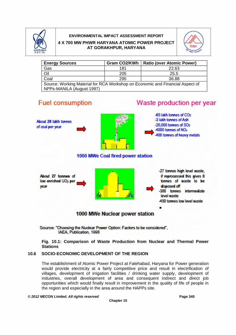
ENVIRONMENTAL IMPACT ASSESSMENT REPORT
4 X 700 MW PHWR HARYANA ATOMIC POWER PROJECT AT GORAKHPUR, HARYANA
© 2012 MECON Limited. All rights reserved Page 340
Chapter 10
Energy Sources Gram CO2/KWh Ratio (over Atomic Power) Gas 181 22.63 Oil 205 25.5 Coal 295 36.88 Source: Working Material for RCA Workshop on Economic and Financial Aspect of NPPs-MANILA (August 1997)
Fig. 10.1: Comparison of Waste Production from Nuclear and Thermal Power Stations
10.6 SOCIO-ECONOMIC DEVELOPMENT OF THE REGION The establishment of Atomic Power Project at Fatehabad, Haryana for Power generation would provide electricity at a fairly competitive price and result in electrification of villages, development of irrigation facilities / drinking water supply, development of industries, overall development of area and consequent indirect and direct job opportunities which would finally result in improvement in the quality of life of people in the region and especially in the area around the HAPPs site.

ENVIRONMENTAL IMPACT ASSESSMENT REPORT
4 X 700 MW PHWR HARYANA ATOMIC POWER PROJECT AT GORAKHPUR, HARYANA
© 2012 MECON Limited. All rights reserved Page 341
Chapter 10
The policy of NPCIL towards social welfare & community development aims at strengthening the bond between the project / station authorities and the local population in the vicinity of nuclear power plants. In line with this policy, NPCIL at the existing stations and projects will carryout a number of community welfare activities in the following areas:
Education – Gyan Gangothri Yojana Health – Arogya Sudha Yojana Community Welfare
The following action plan will be followed for implementing social and community welfare measures in area around the HAPP: NPCIL would contribute in implementing social welfare activities in collaboration with
local Gram Panchayat, Block Development Office etc. for better development of area.
To minimize strain on existing infrastructure, adequate provision of basic amenities, viz. education, health, transport etc. would be made considering the needs of workforce and migrating population.
Sanitation facilities in residential complex and labour colonies would be provided to ensure better hygiene and health
Regular environmental awareness programs would be organised by NPCIL to impress upon the surrounding population about the beneficial impacts of the project and also about the measures being undertaken for environmental safety.
10.7 SOCIO ECONOMIC BENEFITS
Critically analyzing the baseline status of the socioeconomic profile and visualizing the scenario with the project, the impacts of the project would be varied nature. The qualitative impacts on socioeconomic environment due to the project is shown in Table 10.3. Due to the project there would be an overall development of the area and job opportunities, which may improve the quality of life in the region.
Table 10.3: Qualitative Impacts on Socio-economic Environnent
SN Parameter Direct Indirect Reversible Irreversible 1. Employment + + • + 2. Income + + • + 3. Transport • + • + 4. Education • + • + 5. Medical facilities • + • + 6. Communication • + • + 7. Availability of power supply + • • + 8. Sanitation • + + • 9. Housing • + • + 10. Health • + + • 11. Agriculture + • • + 12. Cost of living • + • +

ENVIRONMENTAL IMPACT ASSESSMENT REPORT
4 X 700 MW PHWR HARYANA ATOMIC POWER PROJECT AT GORAKHPUR, HARYANA
© 2012 MECON Limited. All rights reserved Page 342
Chapter 10
SN Parameter Direct Indirect Reversible Irreversible 13. Business + + • + 14. Per Capita Income • + • +
+ Positive Impact -Negative Impact • Insignificant 10.8 EMPLOYMENT POTENTIAL
10.8.1 Skilled and Semi-skilled Skilled and Semi-skilled employment potential in terms of indirect employment of the proposed project will be non-marginal and will usually remain widespread across a long region. The proposed project will cause generation of income and employment opportunities the ancillaries and service units which will came in the vicinity of the plant, specifically, in transport and manufacturing sectors. The project is expected to generate substantial indirect employment in other sectors. Overall assessment of the employment and income effects indicates that the project has strong positive direct as well as indirect impact on employment and income generation of the area.
10.8.2 Un-skilled Unemployment for un-skilled workers is quite common in the study area. The present project has employment generation potential by way of recruiting local people directly for different activities of the project, specifically at the construction phase. It is expected that substantial portion of the investment in this project will trickle down to the local people in the form of employment and income.
10.8.3 Direct Employment Opportunities with NPCIL
Preference will be given by NPCIL to one person per nuclear family of PAFs in providing employment in the project in categories as per details given below, subject to the availability of vacancies and the suitability of person for the employment.
Employment Opportunities with Contractors A large Number of Contract labours would be required during, construction. This includes skilled, semi skilled and unskilled workers. Suitable provisions are proposed to be made in all contracts to the effect that the PAFs shall be given, preference in jobs as per their suitability and skill under the respective contract. Opportunities available may be as under.
Assistance in Training and Skill Development NPCIL proposes to provide assistance, sponsoring, training for skill development to the wards of PAFs as well as to other meritorious students in the area around the site for availing various job opportunities. In brief, the following are proposed:
Opportunities for Self Employment NPCIL, as a policy, provides opportunities to PAFs for self employment during

ENVIRONMENTAL IMPACT ASSESSMENT REPORT
4 X 700 MW PHWR HARYANA ATOMIC POWER PROJECT AT GORAKHPUR, HARYANA
© 2012 MECON Limited. All rights reserved Page 343
Chapter 10
construction, operation and maintenance phase of the Plant. This also meets the provisions of National and State R&R Policy. The brief details are given below:
Award of Small Value Contracts to “Registered Local Societies” NPCIL promotes formulation of Registered Societies consisting of members from local including Project affected families. These Societies are proposed to be given small value contracts for auxiliary services such as Housekeeping, Gardening, Transport service etc. with the provisions to deploy as much Project affected persons in the project as possible.
These societies will be awarded various contracts like (i) contract for Housekeeping to maintain the Liaison Office-cum-transit Guest House of HAPP at Fatehabad, (ii) contract to meet transport service requirement of the Liaison Office at Hisar and (iii) contract for providing fabricated wooden boxes for storage of borehole logs at the site.
Allotment of Shops in Residential Complex NPCIL also propose to provide allotment of shops in Shopping Centre of Residential Complex at HAPP like Milk Vending, Barbershop, Washer man shop, Vegetable shops, Communication centre, Chemist shop etc. through Registered Societies.
10.9 OTHER INDIRECT BUSINESS OPPORTUNITIES
During the construction phase of APP, various contractors will be executing works at the site. They will be required to deploy contract labour in different categories depending on the requirement of skill etc. The strength of the percentage of contract labours will gradually increase from the beginning and at peak the number may increase to 5000 to 8000. All these labourers will be staying in the labour camp to be established inside the property boundary of HAPP site. Each of such family will be spending a minimum of Rs.1500 to 2000 per month to meet their day to day needs on grocery, milk, vegetable and other such items. In many cases, these needs have to be met locally and as such, the average expenditure per month on such account will be approximately Rs.1 Crore. Therefore, this will provide ample business opportunities to the local people around the site.
10.10 IMPROVEMENTS IN PHYSICAL INFRASTRUCTURE
The proposed project will bring about improvement in physical infrastructure in the area. The basic features like, roads, electricity availability, drinking water availability, etc are also expected to improve. It is expected that a similar trend will follow with the proposed project at Fatehabad, Haryana.

ENVIRONMENTAL IMPACT ASSESSMENT REPORT
4 X 700 MW PHWR HARYANA ATOMIC POWER PROJECT AT GORAKHPUR, HARYANA
© 2012 MECON Limited. All rights reserved Page 344
Chapter 10
10.11 OTHER TANGIBLE BENEFITS
10.11.1 Education The local peoples’ interest towards education will increase due to the expectation of
getting jobs, especially from non-agricultural sources such as the industries (which are expected to grow in the vicinity of the proposed project.
The project is expected to increase such aspirations by bringing opportunities of some direct & indirect employment for the local people.
The general awareness towards the importance of education is expected to increase as a result of the new project.
The project will have positive impact on the level of education of the people of the study area.
10.11.2 Other Benefits
The electricity generated in plant will result in electrification of villages, development
of irrigation facilities, drinking water supply, development of industries etc Development in housing, education, medical, health, sanitation, power supply,
electrification and transport in the study area
10.11.3 Industrialisation Around the Proposed Project
The atomic power plant will serve as the nuclei for development of small-scale industries in the area. These small-scale units usually have input-output linkages with the plant and township. The demand for spares, assemblies and sub-assemblies by the plant and township generally met through the supply (of these items) from small-scale units located nearby.
The present project is likely to accelerate such industrialization through “Bubble Effects” in the study area. It is important to note that the small-scale units are usually labour-intensive and high-priority industries from social point of view.
The proposed project is expected to serve as centre of significant small-scale industrial economy around it complemented by the services sector. This is expected to play a major role in the future economic and social development of this area.
10.11.4 Pattern of Demand
The socio-economic questionnaire survey reveals that the respondents spend major portion of their disposable income on food items. However, the respondents are heavily influenced by the changing demand pattern of fast growing Indian consumer society. There has been a tendency among the respondents of allocating higher expenditure on non-food items although their basket of consumption has only few items other than food.

ENVIRONMENTAL IMPACT ASSESSMENT REPORT
4 X 700 MW PHWR HARYANA ATOMIC POWER PROJECT AT GORAKHPUR, HARYANA
© 2012 MECON Limited. All rights reserved Page 345
Chapter 10
With the implementation of the project and development of the locality, existing demand pattern is likely to continue which indicates more importance on consumer goods and quality products. This will affect the local consumer goods market will grow, thus creating more income opportunities to the local people
10.11.5 Consumption Behaviour
Presently in the area the major portion of total consumption expenditure goes to meet the need for food followed by expenditure on clothing, expenditure of social requirements and expenditure on medical services. The expenditure on education in the study area is observed to be medium. The proposed project is going to have positive income effect and consequently, the multiplier effect is expected to lead to an overall increase in average consumption of the people of the study area. After the implementation of the proposed project, average family income of the study area is likely to grow. As income increases, Marginal Propensity to Consume (MPC) will rise in first three years and then will taper down.


ENVIRONMENTAL IMPACT ASSESSMENT REPORT
4 X 700 MW PHWR HARYANA ATOMIC POWER PROJECT AT GORAKHPUR, HARYANA
© 2012 MECON Limited. All rights reserved Page 346
Chapter 11
CHAPTER 11 : ENVIRONMENTAL MANAGEMENT PLAN
11.0 ENVIRONMENTAL MANAGEMENT PLAN 11.1 GENERAL
Environmental Management Plan is the formulation, implementation and monitoring of environmental protection measures during and after commissioning of the project. Objectives of EMP Ensure the mitigation measures are implemented Establish systems and procedures for this purpose Monitor the effectiveness of mitigation measures and Take any necessary action when unforeseen impact occur Components of EMP 1. Careful consideration of the site for its suitability to the proposed activity - described
in Chapter 2, Section 2.4. 2. Potential impact (based on baseline environmental study) & proposed mitigation
measures for different stages of the project - Chapter 5, “Impacts and Mitigation Measures”.
3. Installation of state of art pollution / radiation level control equipment and devices as described in Chapter 6 “Technological Mitigation Measures”.
4. Various measures proposed to be taken including cost components (Section 7.6.4, Chapter 7).
5. Adopting a very strong monitoring / analysis programme - Chapter 7, “Environmental Monitoring Programme”.
6. Administrative and technical setup for management of environment for: - Monitoring facilities setup - For regular and periodic monitoring of indicator parameters. - Regular analysis of the results of the Environmental Monitoring to ensure that
the indicator parameters are within the stipulated norms vis-à-vis the adopted mitigation measures are working efficiently.
- Periodic review by the higher management to see that the monitored indicator parameters are within the expected range and if not – to draw the intervention of higher management.
- Institutional arrangements proposed with other organizations / Govt. authorities for effective implementation of environmental measures proposed in the EIA, .
Point number 1 to 5 of the EMP have been covered as referred above, the organizational setup for environmental monitoring is being presented hereunder under Section 11.3.

ENVIRONMENTAL IMPACT ASSESSMENT REPORT
4 X 700 MW PHWR HARYANA ATOMIC POWER PROJECT AT GORAKHPUR, HARYANA
© 2012 MECON Limited. All rights reserved Page 347
Chapter 11
11.2 ORGANIZATION POLICY The importance of environmental control has been recognised by project proponent at the organizational level. “Environment Management” has been declared as one of its thrust areas of operation in the proposed project and other units. Accordingly NPCIL has a Corporate Environmental Policy approved by CMD, NPCIL. The above objective has been intended to be achieved through the following:
i) Using automation & Computer control to have state of the art technology. ii) Pollution Monitoring and Control, iii) Occupational health set up including regular medical monitoring of employees, iv) A well developed safety management organisation, v) Preparation of Emergency / Disaster Control plan and a properly trained group to
meet the emergency situations, vi) Green belt development inside the plant and surroundings. vii) Development of awareness in employees and public including student population
towards environmental preservation, viii) R & D activities in regard to specific pollution problems.
The proposed project has given maximum importance for adopting latest technologies for keeping the pollution to minimum levels. A separate Environment Survey Laboratory will be set up with an Environmental Laboratory with latest monitoring instruments.
11.3 ORGANISATIONAL SET UP 11.3.1 Administrative Set Up
At the project, an Environmental Management Apex Review Committee (EMARC) will be formed, which will review the effectiveness of environmental management system of the project / station in line with ISO-14001 & BS OHSAS 18001 (Occupational Health and Safety) monitor the effectiveness of Environmental Management Programs (EMP) implementation at the project.
During operation stage different issues / components involved in environmental monitoring programme will be looked upon by Environmental Survey Laboratory (ESL), Health Physics Unit, Chemical laboratory, Waste management Unit (WMU), Medical Unit, Civil Maintenance, Maintenance Unit, Horticulture Unit / Service Maintenance, Central Material & Management, Industrial Safety and Corporate Social Responsibility (CSR) Unit / Human Resources Group. All the above mentioned units responsible for different aspects of monitoring will periodically report the progress of the environmental monitoring programme to TSU for review and necessary action (if required). The reporting arrangement of different units responsible for environmental monitoring programme during construction and operation phase is given under Section 7.6.2, Chapter 7.

ENVIRONMENTAL IMPACT ASSESSMENT REPORT
4 X 700 MW PHWR HARYANA ATOMIC POWER PROJECT AT GORAKHPUR, HARYANA
© 2012 MECON Limited. All rights reserved Page 348
Chapter 11
The person responsible for taking care of all environmental issues at Technical services Unit (TSU) will be of the rank of General Manager (GM). In his day-to-day work, DGM (Environment) will be assisted by three Managers namely, Manager (Environment) of Wate Management Unit (WMU) and Station Chemist from Chemical laboratory and Station Health Physist from Health Physics Unit (HPU). These three Laboratories on requirement may further include Technicians / Laboratory Assistants. The organizational chart at the project and the proposed manpower required to undertake the environmental aspects of the proposed APP is given in Fig. 11.1.
During operation stage, for monitoring of radiation outside exclusion zone is done by Environmental Survey Laboratory under Health Physics Division, BARC, which reports to BARC with intimation to Station Director (SD)..
The organizational composition for other departments like Infrastructure Unit
(Department), Health Physics Unit, Medical Unit, Horticulture Unit, Industrial Safety group and Corporate Social Responsibility (CSR) Unit, responsible for different aspects of environmental monitoring programme, will be framed before the start of construction / operation phase of the project. Here only orgainsational set-up looking after environmental monitoring is being presented, which is responsible for major portion of environmental monitoring programme (Table 7.3 Part A and Table 7.4).
Figure No. 11.1: Organisation Chart Proposed for Environmental Monitoring
11.3.2 Environmental Laboratory Set Up and Space A well-equipped environmental setup has been proposed for Chemical laboratory, Waste Management Unit and Health Physics Unit laboratory. These laboratories will be well-equipped environmental setup laboratory inside the plant premises covering an area of 600m2, with 24 hour water availability to the tune of 3.0 m3/d and electricity power requirement up to 20 KW. These laboratories will have skilled and trained personnel for conducting monitoring and analysis.
STATION CHEMIST
CHEMICAL LAB
INCHARGE WASTE
MANAGEMENT UNIT
STATION HEALTH
PHYSISTS HPU
Group of Scientific Officers / Scientific
Assistants & Technician(s)
Group of Scientific Officers / Scientific
Assistants & Technician(s)
Group of Scientific Officers / Scientific
Assistants & Technician(s)

ENVIRONMENTAL IMPACT ASSESSMENT REPORT
4 X 700 MW PHWR HARYANA ATOMIC POWER PROJECT AT GORAKHPUR, HARYANA
© 2012 MECON Limited. All rights reserved Page 349
Chapter 11
The personnel deployed in the laboratory will be given training to carry out necessary environmental monitoring including radiation monitoring as well as analysis. The recruited officers shall be adequately trained to undertake the environmental requirements of the proposed plant. The requirement of equipments for carrying out environmental monitoring and frequency of the use of different equipments for the proposed plant is given in Table 11.1.
Table 11.1: Monitoring / Analytical Equipments Required
Monitoring Equipments SN. Equipments Numbers
Required
Parameter / Function Frequency
Air / Stack / Noise Monitoring 1. PM2.5 & PM10 sampler
along with gaseous sampling assembly
3 PM2.5 & PM10; SO2, NOX, O3 NH3, As, Ni & Benzo-a-pyrine (BaP) - sampling
24 hr continuous; Once per month
2. Stack Monitoring Kit (manual)
2 SPM Once per month
3. Portable Flue Gas Analyser for stack monitoring
2 CO% SO2 mg/m3 NOX mg/m3 NO mg/m3 CXHY PM Temperature
Once per month
4. Continuous AAQ Monitoring Station SO2, NOx, CO & PM2.5 & PM10
3 PM10, PM2.5, SO2, NOx & CO Continuous
5. Sound Level Meter 2 Noise Level As and when required
Meteorological Monitoring 6. Automatic Weather
Monitoring Station 1 Meteorological parameters Continuous
Water Monitoring & Chemical Analysis 7. Ion Analyser with Auto-
titrator 1 NH3, CN, F Regularly
8. Hot Air Oven 1 Moisture content & drying of samples glassware
Regularly
9. Hot Plate 2 O&G Iron & various purpose like boiling & digestion of sample
Regularly
10. Muffle Furnace 1 Digestion at higher temp, up to 1000°C
As and when required
11. BOD Incubator 1 BOD Twice in a week 12. BOD Apparatus, Oxitop
(1 set of 6) 1 BOD Twice in a week
13. DO Meter 1 BOD As and when required
14. Spectrophotometer 1 COD, NO3 – N PO4 - P
Regularly
15. COD Digestion 1 COD Regularly

ENVIRONMENTAL IMPACT ASSESSMENT REPORT
4 X 700 MW PHWR HARYANA ATOMIC POWER PROJECT AT GORAKHPUR, HARYANA
© 2012 MECON Limited. All rights reserved Page 350
Chapter 11
Monitoring Equipments SN. Equipments Numbers
Required
Parameter / Function Frequency
Assembly 16. pH meter 2 pH Regularly 17. Conductivity Meter 1 TDS Regularly 18. AAS along with Graphite
furnace, Hydride Generator and Cold Vapour Technique
1 Heavy metals in water & As & Ni analysis
As and when required
19. Digital Micro-Balance 2 Weighing Regularly 20. Digital Top Load
Balance (Range 1 to 500g)
1 Weighing Regularly
21. Filtration Apparatus 2 SS / MLSS Regularly 22. Heating mental 3 Distillation Regularly 23. Refrigerator 2 Preservation of chemicals and
samples Regularly
24. Fuming Chamber 1 For exhaust As and when required
25. Water Bath 2 Evaporation of sample As when required 26. Vacuum pump 2 Hardness alkalinity etc. As and when
required 27. Turbidity Meter 1 Turbidity As and when
required 28. Filter Papers,
Glassware, Plastic wares, Chemicals
In Lot
Radiation Monitoring 29. High Volume Air
samplers 2 Sample collection for radiation
monitoring Regularly
30. Ashing equipment 1 Sample processing for radiation monitoring / analysis
Regularly
31. Portable survey meter 4 Radiation monitoring Regularly 32. Contamination Monitors
(beta–gamma & alpha) 2 -do- Regularly
33. Scintillometer 2 -do- Regularly 34. Alpha counting system 1 -do- Regularly 35. Beta counting system 1 -do- Regularly 36. Low beta counting
system 1 -do- Regularly
37. Gas proportional counting system
1 -do- Regularly
38. Liquid scintillation counting system
1 -do- Regularly
39. Gamma Ray Spectrometer - NaI (Tl)
1 -do- Regularly
40. Gamma Ray Spectrometer - HpGe
1 -do- Regularly
41. Whole body counter 1 -do- Regularly

ENVIRONMENTAL IMPACT ASSESSMENT REPORT
4 X 700 MW PHWR HARYANA ATOMIC POWER PROJECT AT GORAKHPUR, HARYANA
© 2012 MECON Limited. All rights reserved Page 351
Chapter 11
Monitoring Equipments SN. Equipments Numbers
Required
Parameter / Function Frequency
42. Instrumented Meteorological tower
1 -do- Regularly
43. Portable Diesel Generator set
1 -do- Regularly
44. Filter Papers, Glassware, Plastic wares, Chemicals
In Lot -do- Regularly
11.3.3 Functioning
Environmental monitoring programme and its reporting has been designed to provide a close watch on the surrounding environment and provide early warnings of any adverse changes that may be related to some dimension of the plant’s operations. The Environmental Survey Laboratory (ESL) of BARC and Waste Management Unit (WMU), Chemical Laboratory and Health Physics Unit (HPU) will look after the major portion of the environmental aspects, carry out day to day environmental monitoring / inspection requirements and maintain records. These laboratories will look after the radiation monitoring, complete air monitoring, noise level monitoring, special monitoring on water and air, effluent, special surveys and impact assessment and solid waste management. The over all responsibility matrix of monitoring different aspects of environmental monitoring plan are given in Table 7.3A and 7.4, Chapter 7.0. Part or total of the environmental monitoring programme will be carried out through external agencies on a contract basis. However, casual labourers etc. will be employed for plantation, drain cleaning etc as and when required.
The TSU shall frequently analyse the data and periodically assess the progress of the EMP.
11.4 IMPLEMENTATION ARRANGEMENT 11.4.1 Institutional Implementation Arrangements
The project proponent is responsible for implementation of all the mitigation and management measures suggested in Environmental Monitoring Programme. The Technical Services Unit will look after all environmental related matters of the plant. In addition an Environmental Management Apex Review Committee (EMARC) at the higher Management Level will be set up for the smooth implementation of Environment Management Plan. EMARC will review the effectiveness of environmental management system of the project / station in line with ISO-14001 & BS OHSAS 18000 (Occupational Health and Safety) monitor the effectiveness of Environmental Management Programs (EMP) implementation at the project.

ENVIRONMENTAL IMPACT ASSESSMENT REPORT
4 X 700 MW PHWR HARYANA ATOMIC POWER PROJECT AT GORAKHPUR, HARYANA
© 2012 MECON Limited. All rights reserved Page 352
Chapter 11
The EMARC will consist of heads of different sections of the project. The Project Director / Station Director will be overall In-charge of the Project / Station. The role of the EMARC would be to review the implementation of all environment related matters. TSU and other units of the plant looking after different aspects of environmental monitoring programme, will report all the environmental matters to PD / SD as per the reporting schedule on prescribed formats. The EMARC will review the reported activity from time to time for smooth implementation of Environmental Mitigation and Management measures and will suggest necessary actions if required. For successful implementation of the environmental management plan other agencies of the State may also be involved, if required (for regulatory requirement or technical support). The coordinating agencies, which may be involved for specific environmental related activities, are given in Table 11.2.
Table 11.2: List of Coordinating Agencies, which may be involved for specific Environmental Activities
SPCB DOH DDA State Level Agency SFD Chairman Chief Engineer Chief Engineer
District Level DFO RO Ex. Engineer Ex. Engineer Project Area: Plantation Programme Study Area: Air, noise, water quality, soil, waste water discharge quality monitoring. Radiation Monitoring
Study Area: CSR Activities Project Area: Stack monitoring, work-zone noise, effluents from outlet of STP.
Project Area: Solid / Hazardous Waste Disposal Project Area: Radiation Monitoring & Human Health
Study Area / Project Area Interface: Road safety measures
Index: SFD – State Forest Department SPCB – State Pollution Control Board DOH – Department of Health DDA – District Development Authority DFO – Divisional Forest Officer
RO – Regional Officer State Pollution Control Board Local NGOs will also be identified at the district and block level to provide help and advice for implementation of EMP especially on matters related to community development programmes.
11.4.2 Co-ordination with Other Departments The Technical services Unit (TSU) will also co-ordinate with other departments of HAPP like Occupational Health, Safety Management, Project Engineering, Horticulture and

ENVIRONMENTAL IMPACT ASSESSMENT REPORT
4 X 700 MW PHWR HARYANA ATOMIC POWER PROJECT AT GORAKHPUR, HARYANA
© 2012 MECON Limited. All rights reserved Page 353
Chapter 11
Corporate Social Responsibility (CSR) Unit, Water Supply Department etc. and also do the liaison work with external agencies like State Pollution Control Board..
11.4.3 Interaction with State Pollution Control Board TSU shall be in regular touch with SPCB and shall send them quarterly progress report on EMP in the prescribed format, as per the prevailing practice of the Board. Any new regulations considered by State Pollution Control Board / Central Pollution Control Board for the Industry shall be taken care of by responsible units.
11.4.4 Training The different laboratories and departments who would be responsible for the implementation of the EMP, needs to be trained on the effective implementation of the environmental issues. To ensure the success of the implementation set up proposed, there is a high requirement of training and skill up-gradation. For the proposed project, additional training facilities will be developed for environmental control. For proper implementation of the EMP, the officials responsible for EMP implementation will be trained accordingly. To achieve the overall objective of pollution control it is essential not only to provide latest pollution control and monitoring systems but also to provide trained man power resources to operate and maintain the same. So far, the practice with many plants is to utilize the plant operations and maintenance crew for operation of systems. This has shown adverse results due to lack of specialized knowledge in addition to priority selection. Therefore apart from the different laboratories involved, specific training will be provided to personnel handling the operation and maintenance of different pollution / radiation control equipments. In-plant training facilities will be developed for environmental control. Specialised courses at various Research / Educational institutes will be organised. The training will be given to employees to cover the following fields:
Awareness of pollution control and environmental protection to all. Operation and maintenance of specialised pollution / radiation control equipment. Field monitoring, maintenance and calibration of pollution / radiation monitoring
instruments. Laboratory testing of pollutants / radiation. Repair of pollution monitoring instruments. Occupational health/safety. Disaster management. Environmental management. Afforestation / plantation and post care of plants. Knowledge of norms, regulations and procedures. Risk assessment and Disaster Management.

ENVIRONMENTAL IMPACT ASSESSMENT REPORT
4 X 700 MW PHWR HARYANA ATOMIC POWER PROJECT AT GORAKHPUR, HARYANA
© 2012 MECON Limited. All rights reserved Page 354
Chapter 12
CHAPTER 12 : SUMMARY & CONCLUSION
12.0 SUMMARY & CONCLUSION
Executive summary of the entire EIA study is being submitted as a separate report. However in this chapter the brief summary and conclusion of the study is being highlighted.
In the design phase of the Project Environmental Impact Assessment (EIA) was done to assess the possible impacts of the proposed APP. In the plant design itself latest state of art technology has been envisaged so as to achieve the desired air emissions and noise levels from plant operation levels and the effluent quality at the outlet below statutory norms. Further, maximum re-use and re-utilisation of generated solid waste has been envisaged.
Primary and secondary data were used to assess the environmental impacts of the proposed project. The potential environmental impacts were assessed in a comprehensive manner. All the potential environmental impacts associated with different phases (i.e, during design or pre-construction, construction and operation) of the Project were assessed.
The EIA report has thoroughly assessed all the potential environmental impacts associated with the project. The environmental impacts identified by the study are manageable. The implementation of environmental mitigation measurers recommended in the report will bring the anticipated impacts to minimum.
Site specific and practically suitable mitigation measures are recommended to mitigate the impacts. Further, a suitable monitoring plan has been designed to monitor the effectiveness of envisaged mitigation measures during the operation phase.
The introduction of state of art technology (including the technological mitigation measures) during the design has limited the environmental impacts related with the Project. The implementation and monitoring of effectiveness of the environmental mitigation measures during the operation phase will be assigned to the Technical Services Unit (TSU) of the project. An Environmental Management Apex Review Committee (EMARC), comprising of senior management level officers will periodically assess and monitor the implementation of mitigation measures, and will tackle the management bottle necks of implementation of mitigation measures and environmental monitoring programme. It is concluded that with the implementation of EMP, project will not have any adverse impact on the environment. Moreover the project will provide green house gases free electricity to the state of Harayana in particular and to the country in general and also will provide direct and indirect employment opportunities to the people of the area/region and uplift their socio-ecomonic status.


ENVIRONMENTAL IMPACT ASSESSMENT REPORT
4 X 700 MW PHWR HARYANA ATOMIC POWER PROJECT AT GORAKHPUR, HARYANA
© 2012 MECON Limited. All rights reserved Page 355
Chapter 13
CHAPTER 13 : DISCLOSURE OF CONSULTANT
13.0 DISCLOSURE OF CONSULTANT
The EIA report has been prepared by MECON Limited, a Public Sector undertaking under the Ministry of Steel Government of India, is a premier multi disciplinary planning, design, engineering and consultancy organisation in the country in the field of ferrous, non-ferrous, thermal, petrochemical, defense and other related projects and in the field of environment. MECON's Head Office is at Ranchi and site offices in Bangalore, New Delhi, Bhubenashwar, Pune, Vyzak, Bhailai, Durgapur, Raurkela, Bokaro, and many other places in the country. The Environmental Engineering Division of MECON has provided services for more than 200 numbers of Environmental projects. MECON’s Environmental Engineering Division is a multi-disciplinary group of engineers, specialists and scientists whose services are backed up by a sophisticated Environmental Engineering Laboratory recognized by Ministry of Environment & Forest and several State Pollution Control Boards. There are specialists in the field of hydrogeology, geology, ecology, forestry, microbiology, biotechnology, audit & socio–economics and engineers from different disciplines. MECON has been preparing regularly EIA / EMP reports for different projects. MECON also renders its services for rehabilitation action plan for affected people, inspection and audit including environmental audit, etc. National Accreditation Board for Education and Training (NABET) - under the Accreditation Scheme for EIA Consultant Organisations has accredited MECON Limited as EIA consultant for 16 EIA Sectors, vide NABET notification dated 24.03.11. The list of sectors for which the accreditation has been accorded by NABET is given in Table 13.1. The same can be referred from the NABET website “www.qcin.org/nabet/about.php “, by following the link - EIA Accreditation Scheme – Accreditation Register – Accredited Consultant - “List of Accredited Consultants with Scope (Rev. 02) dated 18th August 2011.”. The present EIA study pertains to an ‘Atomic Power Project (APP)’, which falls under the category “Nuclear power projects and processing of nuclear fuel”.
Table 13.1: List of Sectors for which NABET has given Accreditation SN. Sector Details Accreditation for
Category of Project
1. Mining of minerals including Opencast / Underground mining A 2. Only Offshore oil and gas exploration, development & production A 3. River Valley, Hydel, Drainage and Irrigation projects A 4. Thermal Power Plants A 5. Coal washeries A 6. Mineral beneficiation including pelletisation A 7. Metallurgical industries (ferrous & non ferrous) – both primary and
secondary A

ENVIRONMENTAL IMPACT ASSESSMENT REPORT
4 X 700 MW PHWR HARYANA ATOMIC POWER PROJECT AT GORAKHPUR, HARYANA
© 2012 MECON Limited. All rights reserved Page 356
Chapter 13
SN. Sector Details Accreditation for Category of Project
8. Cement plants A 9. Coke oven plants A 10. Induction/arc furnaces/cupola furnaces/submerged arc
furnace/crucible furnace/re-heating furnace of capacity more than 5Tonne per heat.
A
11. Oil & gas transportation pipeline (crude and refinery/ petrochemical products), passing through national parks/ sanctuaries/coral reefs / ecologically sensitive areas including LNG terminal
A
12. All ship breaking yards including ship breaking units A 13. Industrial estates/ parks/ complexes/areas, export processing Zones
(EPZs), Special Economic Zones (SEZs), Biotech Parks, Leather Complexes
A
14. Ports, harbours, jetties, marine terminals, break waters and dredging A 15. Highways, railways, transport terminus mass rapid transport
systems.
16. Common Municipal Solid Waste Management Facility (CMSWMF) A For “Nuclear power projects and processing of nuclear fuel” sector MECON’s application along with other consultants are still pending at NABET. However, till date NABET has not cleared any application related to nuclear sector.