Embed Size (px)
Citation preview

Kamran Entesari, ELEN 457 Texas A & M University
OPERATIONAL AMPLIFIERS
ELEN - 457
Kamran Entesari
Spring 2006
Kamran Entesari, ELEN 457 Texas A & M University
Outline
• Op Amp fundamentals and ideal macro model
• Non-ideal properties and macro models
• Stability and Noise analysis in Op Amp circuits
• OTA fundamental properties
• Multipliers and nonlinear applications
• Active filters
• Signal generators
• Oscillators
• Switched capacitor techniques
• D/A and A/D converters
• Phase-locked loops
Kamran Entesari, ELEN 457 Texas A & M University
Section 1
1) Op Amp fundamentals and ideal
macro model
2) Circuits with resistive feedback
Kamran Entesari, ELEN 457 Texas A & M University
Op Amp Fundamentals
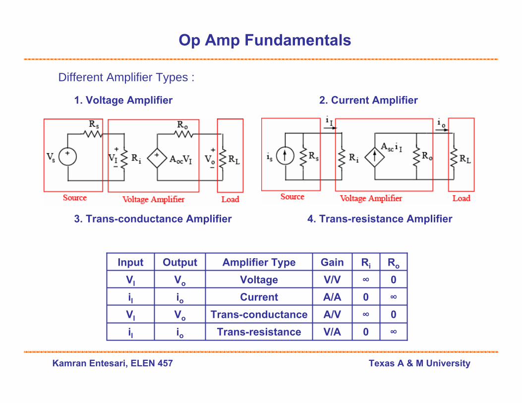
Different Amplifier Types :
2. Current Amplifier1. Voltage Amplifier
3. Trans-conductance Amplifier 4. Trans-resistance Amplifier
∞0V/ATrans-resistanceioiI
0∞A/VTrans-conductanceVoVI
∞0A/ACurrentioiI
0∞V/VVoltageVoVI
RoRiGainAmplifier TypeOutputInput
Kamran Entesari, ELEN 457 Texas A & M University
Op Amp Fundamentals
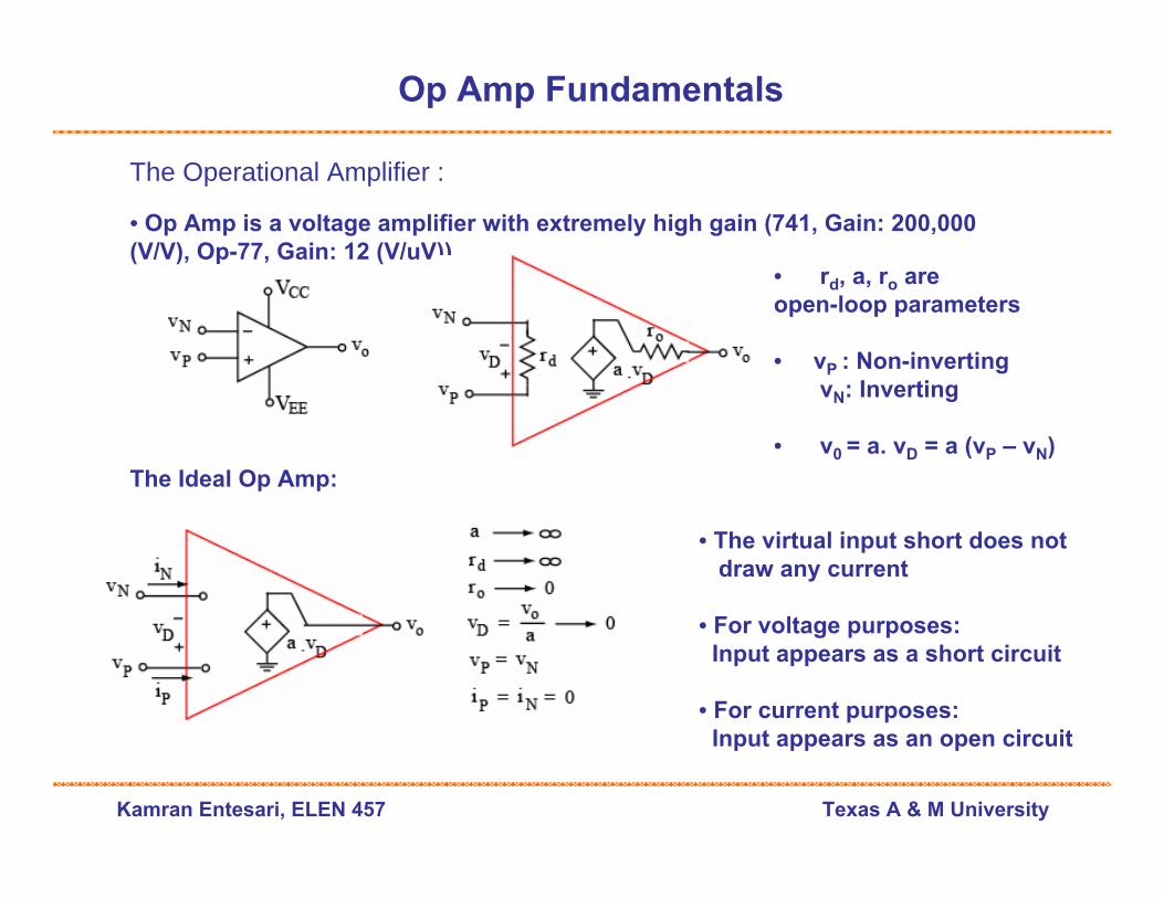
The Operational Amplifier :
• Op Amp is a voltage amplifier with extremely high gain (741, Gain: 200,000 (V/V), Op-77, Gain: 12 (V/uV))
• rd, a, ro are open-loop parameters
• vP : Non-inverting vN: Inverting
• v0 = a. vD = a (vP – vN)The Ideal Op Amp:
• The virtual input short does not draw any current
• For voltage purposes: Input appears as a short circuit
• For current purposes:Input appears as an open circuit
Kamran Entesari, ELEN 457 Texas A & M University
Op Amp Fundamentals
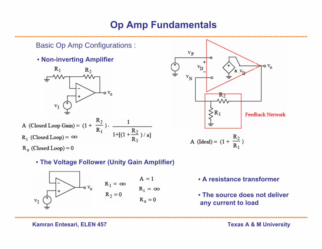
• The Voltage Follower (Unity Gain Amplifier)
Basic Op Amp Configurations :
• Non-inverting Amplifier
• A resistance transformer
• The source does not deliverany current to load

Kamran Entesari, ELEN 457 Texas A & M University
Op Amp Fundamentals
• The Summing Amplifier ( Popular Application : Audio Mixing )
Basic Op Amp Configurations :
• Inverting Amplifier
The output is the weighted sum of the inputs

Kamran Entesari, ELEN 457 Texas A & M University
Op Amp Fundamentals
Basic Op Amp Configurations :
• The Difference Amplifier ( Popular Application : Instrumentation )
• The Differentiator• Tends to oscillate (We see the
reason later)
• By putting the Rs in series withC, the oscillation problem is solved
• The circuit still provides differentiation function over the limited bandwidth

Kamran Entesari, ELEN 457 Texas A & M University
Op Amp Fundamentals
Basic Op Amp Configurations :• The Integrator (Popular Applications: Function generators, Active filters, A/Ds, Analog (PID) controllers )
• The Negative Resistance Converter (NIC)
• Due to the input offset error of the op ampthe output drifts until it saturates at thevalue close to one of the supplies.
• By putting Rp in parallel with C, we can prevent saturation and have integration over a limited bandwidth.
• Current is floating toward the source
• Negative resistance releases the power.
• Applications:1) Neutralization of unwanted resistances
in the design of current source2) Control pole location (Oscillators)
Kamran Entesari, ELEN 457 Texas A & M University
Op Amp Fundamentals
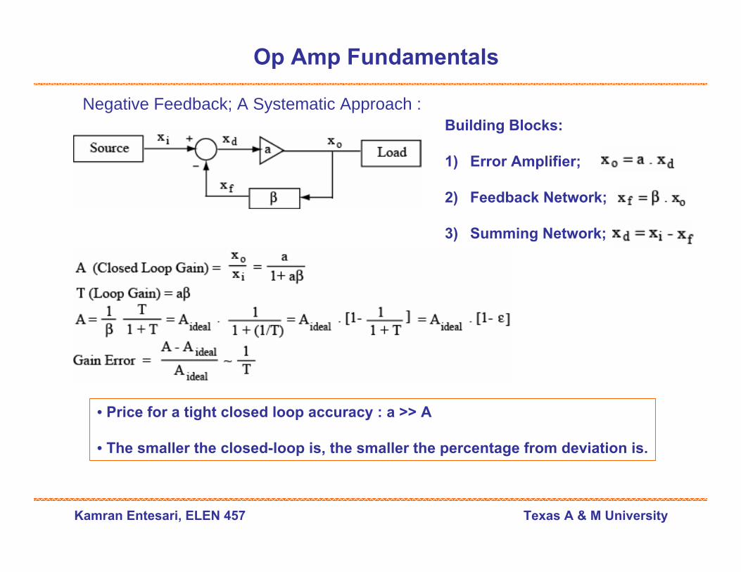
Negative Feedback; A Systematic Approach :Building Blocks:
1) Error Amplifier;
2) Feedback Network;
3) Summing Network;
• Price for a tight closed loop accuracy : a >> A
• The smaller the closed-loop is, the smaller the percentage from deviation is.
Kamran Entesari, ELEN 457 Texas A & M University
Op Amp Fundamentals
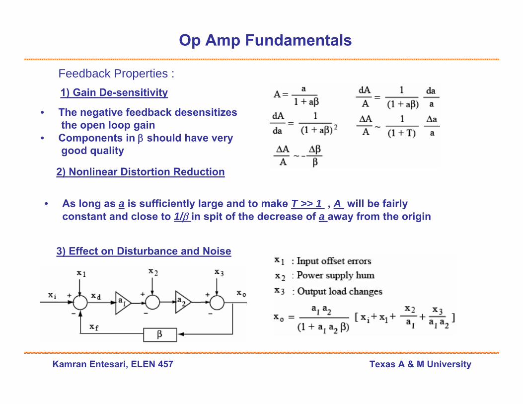
Feedback Properties :1) Gain De-sensitivity
2) Nonlinear Distortion Reduction
3) Effect on Disturbance and Noise
• The negative feedback desensitizes the open loop gain
• Components in β should have verygood quality
• As long as a is sufficiently large and to make T >> 1 , A will be fairlyconstant and close to 1/β in spit of the decrease of a away from the origin
Kamran Entesari, ELEN 457 Texas A & M University
Op Amp Fundamentals
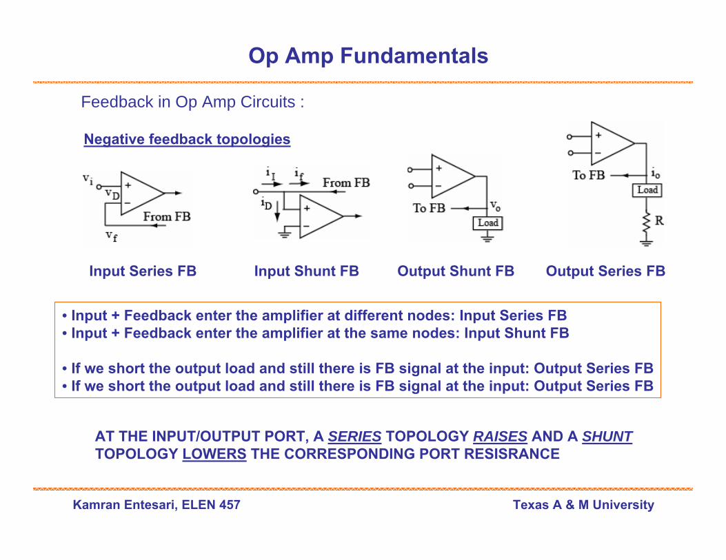
Feedback in Op Amp Circuits :
Negative feedback topologies
Input Series FB Input Shunt FB Output Shunt FB Output Series FB
• Input + Feedback enter the amplifier at different nodes: Input Series FB• Input + Feedback enter the amplifier at the same nodes: Input Shunt FB
• If we short the output load and still there is FB signal at the input: Output Series FB• If we short the output load and still there is FB signal at the input: Output Series FB
AT THE INPUT/OUTPUT PORT, A SERIES TOPOLOGY RAISES AND A SHUNTTOPOLOGY LOWERS THE CORRESPONDING PORT RESISRANCE
Kamran Entesari, ELEN 457 Texas A & M University
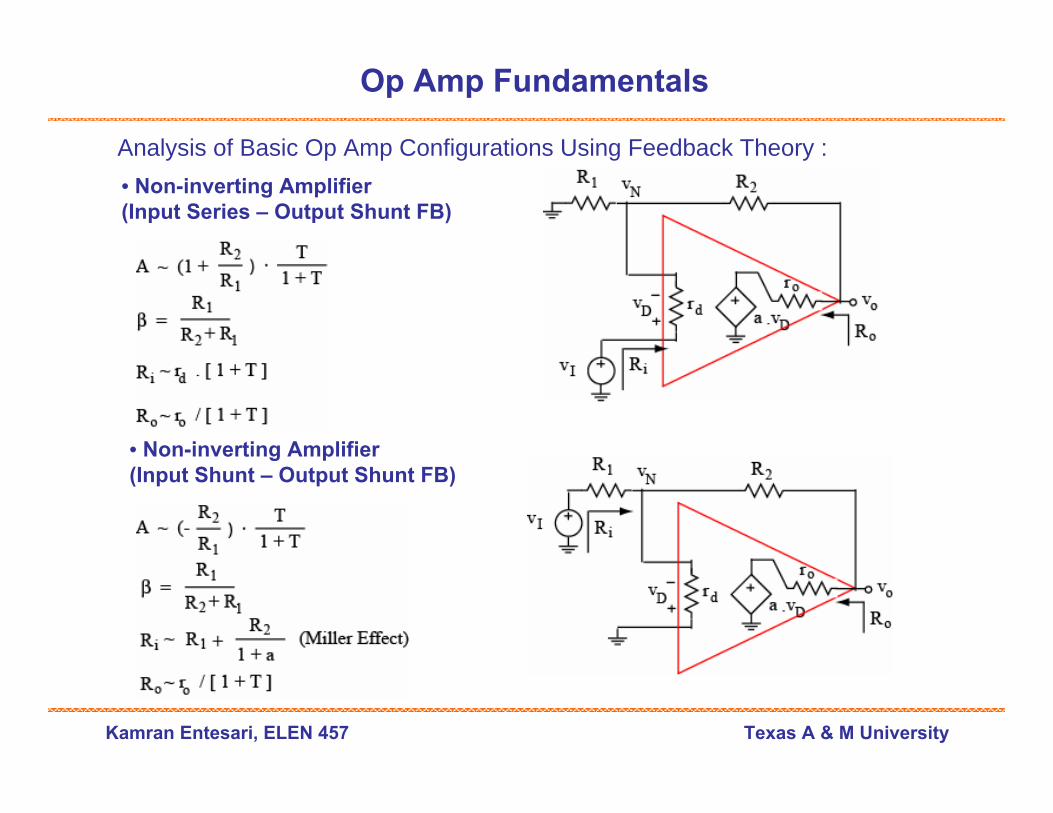
Op Amp Fundamentals
Analysis of Basic Op Amp Configurations Using Feedback Theory :• Non-inverting Amplifier(Input Series – Output Shunt FB)
• Non-inverting Amplifier(Input Shunt – Output Shunt FB)

Kamran Entesari, ELEN 457 Texas A & M University
Op Amp Fundamentals
Finding The Loop Gain (T) Directly:• Suppress all input sources, • Break the loop at some convenient point• Inject the test signal (vT)• Find the return signal (vR) at the breaking point using the feedback path:
Finding the Feedback Factor (β) Directly:
• Suppress all input sources, • Disconnect the op amp• Replace the op amp with its terminal resistances (rd, ro)• Apply a test source vT via ro, find the difference voltage vD across rd, then:
By finding β, using datasheet we can find a and calculate T = a . β
Kamran Entesari, ELEN 457 Texas A & M University
Op Amp Fundamentals
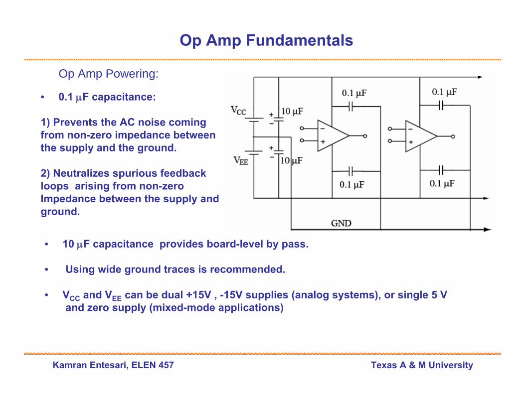
Op Amp Powering:
• 0.1 μF capacitance:
1) Prevents the AC noise coming from non-zero impedance betweenthe supply and the ground.
2) Neutralizes spurious feedback loops arising from non-zeroImpedance between the supply andground.
• 10 μF capacitance provides board-level by pass.
• Using wide ground traces is recommended.
• VCC and VEE can be dual +15V , -15V supplies (analog systems), or single 5 V and zero supply (mixed-mode applications)
Kamran Entesari, ELEN 457 Texas A & M University
Op Amp Fundamentals
Op Amp Powering:
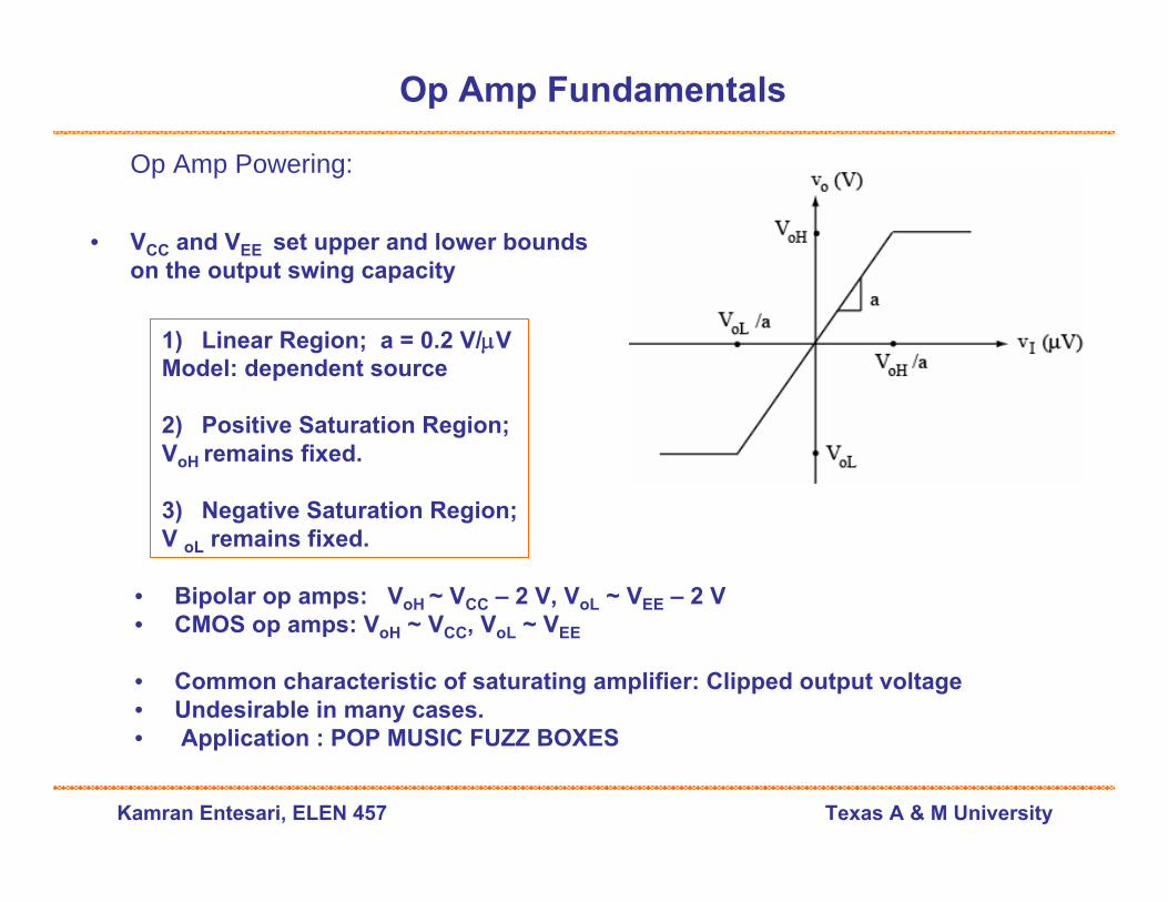
• VCC and VEE set upper and lower bounds on the output swing capacity
1) Linear Region; a = 0.2 V/μVModel: dependent source
2) Positive Saturation Region;VoH remains fixed.
3) Negative Saturation Region;V oL remains fixed.
• Bipolar op amps: VoH ~ VCC – 2 V, VoL ~ VEE – 2 V• CMOS op amps: VoH ~ VCC, VoL ~ VEE
• Common characteristic of saturating amplifier: Clipped output voltage• Undesirable in many cases.• Application : POP MUSIC FUZZ BOXES