Embed Size (px)
Citation preview
www.electrometer.us
Electro
M e t e r
Page
1 of 8
© Electro Meter Order No. Alpha 0 Data sheet-E1.R0-931107-05-EN3
Alpha 03
Version: ALS20/2015/02
Alpha 30 is a compact multifunction instrument which measures important electrical parameters
in 3 phase 4 Wire and 3 phase 3 Wire Network & replaces the multiple analog panel meters.
Special Features
MODBUS (RS485) Communication (optional)
Pulse/Limit Switch output (optional)
3 Line 4 Digits ultra bright LED Display (up to 9999)
On site Programmable CT/PT Ratios
User selectable CT Secondary 1A/5A
Measurement & Display of RPM, Run hours, On hours,
No. of interruption
ElectroM e t e r
www.electrometer.us
Electro
M e t e r
Page
2 of 8
Alpha 30
© Electro Meter Order No. Alpha 30 Data sheet-E1.R0-931107-05-EN
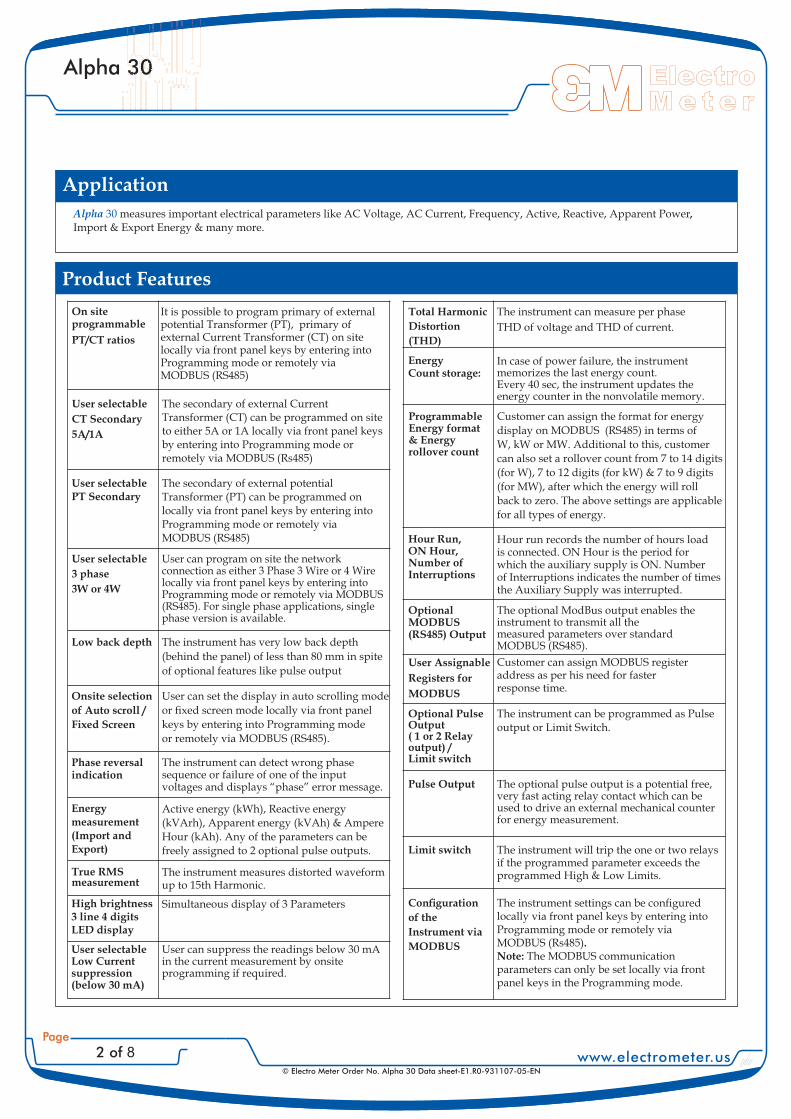
Application
Alpha 30 measures important electrical parameters like AC Voltage, AC Current, Frequency, Active, Reactive, Apparent Power,Import & Export Energy & many more.
Product Features
On siteprogrammable
PT/CT ratios
It is possible to program primary of externalpotential Transformer (PT), primary ofexternal Current Transformer (CT) on sitelocally via front panel keys by entering intoProgramming mode or remotely viaMODBUS (RS485)
User selectable
CT Secondary
5A/1A
The secondary of external CurrentTransformer (CT) can be programmed on siteto either 5A or 1A locally via front panel keysby entering into Programming mode orremotely via MODBUS (Rs485)
User selectablePT Secondary
The secondary of external potentialTransformer (PT) can be programmed onlocally via front panel keys by entering intoProgramming mode or remotely viaMODBUS (RS485)
User selectable
3 phase
3W or 4W
User can program on site the networkconnection as either 3 Phase 3 Wire or 4 Wirelocally via front panel keys by entering intoProgramming mode or remotely via MODBUS(RS485). For single phase applications, singlephase version is available.
Low back depth The instrument has very low back depth
(behind the panel) of less than 80 mm in spite
of optional features like pulse output
Onsite selection
of Auto scroll /
Fixed Screen
Phase reversalindication
The instrument can detect wrong phasesequence or failure of one of the inputvoltages and displays “phase” error message.
Energymeasurement(Import andExport)
Active energy (kWh), Reactive energy
(kVArh), Apparent energy (kVAh) & Ampere
Hour (kAh). Any of the parameters can be
freely assigned to 2 optional pulse outputs.
True RMSmeasurement
The instrument measures distorted waveformup to 15th Harmonic.
High brightness3 line 4 digitsLED display
Simultaneous display of 3 Parameters
User selectableLow Currentsuppression(below 30 mA)
User can suppress the readings below 30 mAin the current measurement by onsiteprogramming if required.
Total Harmonic
Distortion
(THD)
The instrument can measure per phase
THD of voltage and THD of current.
EnergyCount storage:
In case of power failure, the instrumentmemorizes the last energy count.Every 40 sec, the instrument updates theenergy counter in the nonvolatile memory.
ProgrammableEnergy format& Energyrollover count
Customer can assign the format for energy
display on MODBUS (RS485) in terms of
W, kW or MW. Additional to this, customer
can also set a rollover count from 7 to 14 digits
(for W), 7 to 12 digits (for kW) & 7 to 9 digits
(for MW), after which the energy will roll
back to zero. The above settings are applicable
for all types of energy.
Hour Run,ON Hour,Number ofInterruptions
Hour run records the number of hours loadis connected. ON Hour is the period forwhich the auxiliary supply is ON. Numberof Interruptions indicates the number of timesthe Auxiliary Supply was interrupted.
OptionalMODBUS(RS485) Output
The optional ModBus output enables theinstrument to transmit all themeasured parameters over standardMODBUS (RS485).
User Assignable
Registers for
MODBUS
Customer can assign MODBUS registeraddress as per his need for fasterresponse time.
Optional PulseOutput( 1 or 2 Relayoutput) /Limit switch
The instrument can be programmed as Pulseoutput or Limit Switch.
The optional pulse output is a potential free,very fast acting relay contact which can beused to drive an external mechanical counterfor energy measurement.
The instrument will trip the one or two relaysif the programmed parameter exceeds theprogrammed High & Low Limits.
Pulse Output
Limit switch
www.electrometer.us
Electro
M e t e r
Page
3 of 8
Alpha 30
© Electro Meter Order No. Alpha 30 Data sheet-E1.R0-931107-05-EN
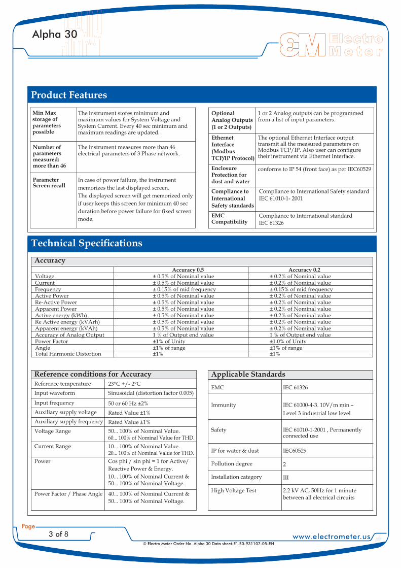
Product Features
The instrument measures more than 46electrical parameters of 3 Phase network.
Min Maxstorage ofparameterspossible
The instrument stores minimum andmaximum values for System Voltage andSystem Current. Every 40 sec minimum andmaximum readings are updated.
Number ofparametersmeasured:more than 46
ParameterScreen recall
OptionalAnalog Outputs(1 or 2 Outputs)
1 or 2 Analog outputs can be programmedfrom a list of input parameters.
EthernetInterface(ModbusTCP/IP Protocol)
EnclosureProtection fordust and water
conforms to IP 54 (front face) as per IEC60529
Compliance to
International
Safety standards
Compliance to International Safety standard
IEC 61010-1- 2001
EMCCompatibility
Compliance to International standard
IEC 61326
Reference conditions for AccuracyReference temperature 23°C +/- 2°C
Input waveform Sinusoidal (distortion factor 0.005)
Input frequency 50 or 60 Hz ±2%
Auxiliary supply voltage Rated Value ±1%
Auxiliary supply frequency Rated Value ±1%
Voltage Range 50... 100% of Nominal Value.60... 100% of Nominal Value for THD.
Current Range 10... 100% of Nominal Value.20... 100% of Nominal Value for THD.
Power Cos phi / sin phi = 1 for Active/
Reactive Power & Energy.
10... 100% of Nominal Current &50... 100% of Nominal Voltage.
Power Factor / Phase Angle 40... 100% of Nominal Current &
50... 100% of Nominal Voltage.
Accuracy 0.5 Accuracy 0.2VoltageCurrentFrequencyActive PowerRe-Active PowerApparent PowerActive energy (kWh)Re Active energy (kVArh)Apparent energy (kVAh)Accuracy of Analog OutputPower FactorAngleTotal Harmonic Distortion
± 0.5% of Nominal value± 0.5% of Nominal value± 0.15% of mid frequency± 0.5% of Nominal value± 0.5% of Nominal value± 0.5% of Nominal value± 0.5% of Nominal value± 0.5% of Nominal value± 0.5% of Nominal value1 % of Output end value±1% of Unity±1% of range±1%
± 0.2% of Nominal value± 0.2% of Nominal value± 0.15% of mid frequency± 0.2% of Nominal value± 0.2% of Nominal value± 0.2% of Nominal value± 0.2% of Nominal value± 0.2% of Nominal value± 0.2% of Nominal value1 % of Output end value±1.0% of Unity±1% of range±1%
Accuracy
Applicable Standards
EMC
Immunity
Safety
IP for water & dust
Pollution degree
Installation category
High Voltage Test
IEC 61326
IEC 61000-4-3. 10V/m min –
Level 3 industrial low level
IEC 61010-1-2001 , Permanentlyconnected use
IEC60529
2
III
2.2 kV AC, 50Hz for 1 minutebetween all electrical circuits
www.electrometer.us
Electro
M e t e r
Page
4 of 8
Alpha 30
© Electro Meter Order No. Alpha 30 Data sheet-E1.R0-931107-05-EN
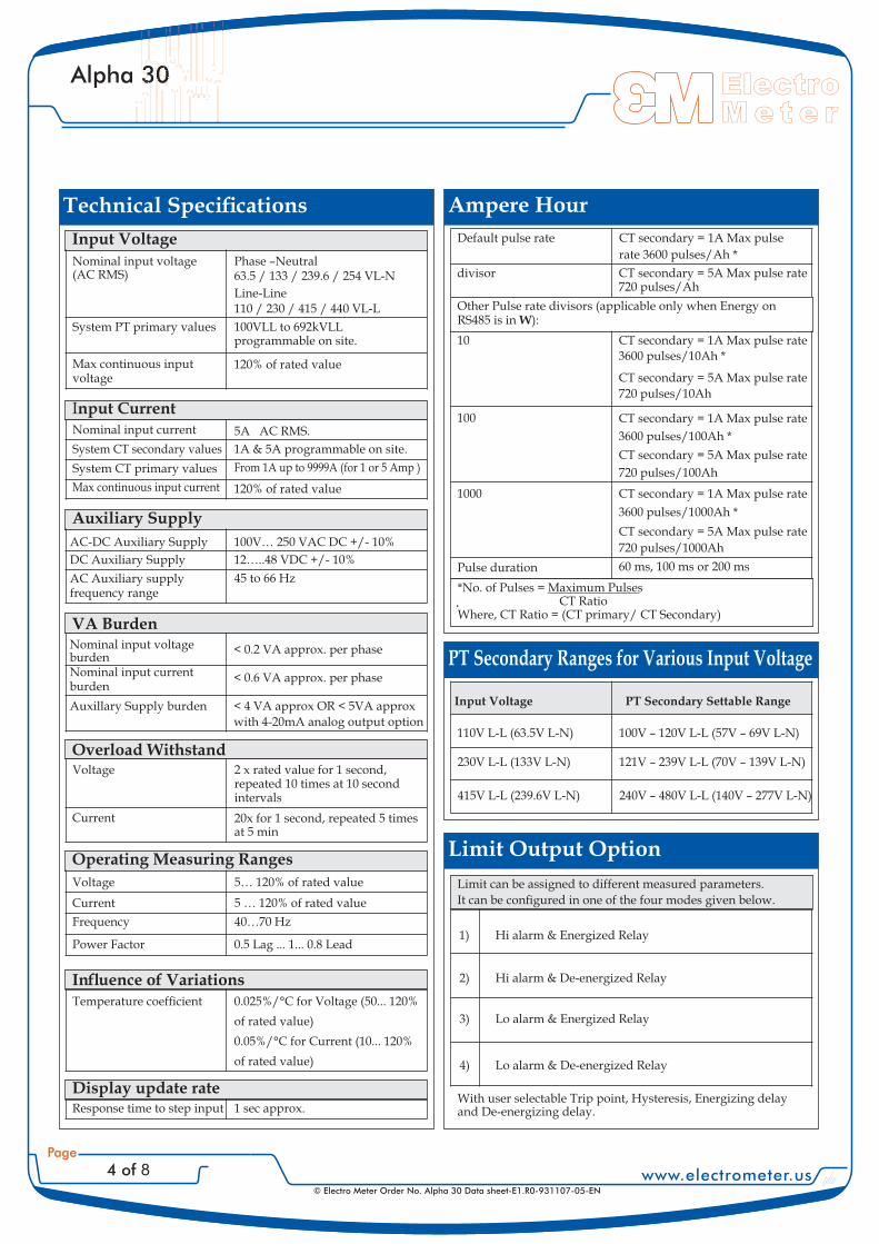
Ampere Hour
Default pulse rate CT secondary = 1A Max pulse
rate 3600 pulses/Ah *
divisor CT secondary = 5A Max pulse rate720 pulses/Ah
Other Pulse rate divisors (applicable only when Energy onRS485 is in ):W
10 CT secondary = 1A Max pulse rate
3600 pulses/10Ah *
CT secondary = 5A Max pulse rate
720 pulses/10Ah
100 CT secondary = 1A Max pulse rate
3600 pulses/100Ah *
CT secondary = 5A Max pulse rate
720 pulses/100Ah
1000 CT secondary = 1A Max pulse rate
3600 pulses/1000Ah *
CT secondary = 5A Max pulse rate
720 pulses/1000Ah
Pulse duration 60 ms, 100 ms or 200 ms
*No. of Pulses = Maximum PulsesCT Ratio
Where, CT Ratio = (CT primary/ CT Secondary)
Input Voltage
Nominal input voltage(AC RMS)
Phase –Neutral63.5 / 133 / 239.6 / 254 VL-N
Line-Line110 / 230 / 415 / 440 VL-L
System PT primary values 100VLL to 692kVLLprogrammable on site.
Max continuous inputvoltage
120% of rated value
Input CurrentNominal input current 5A AC RMS.
System CT secondary values 1A & 5A programmable on site.
System CT primary values From 1A up to 9999A (for 1 or 5 Amp )
Max continuous input current 120% of rated value
Auxiliary Supply
AC-DC Auxiliary Supply 100V… 250 VAC DC +/- 10%
DC Auxiliary Supply 12…..48 VDC +/- 10%
AC Auxiliary supplyfrequency range
45 to 66 Hz
VA BurdenNominal input voltageburden
< 0.2 VA approx. per phase
Nominal input currentburden
< 0.6 VA approx. per phase
Auxillary Supply burden < 4 VA approx OR < 5VA approx
with 4-20mA analog output option
Overload Withstand2 x rated value for 1 second,repeated 10 times at 10 secondintervals
Voltage
Current 20x for 1 second, repeated 5 timesat 5 min
Operating Measuring Ranges
Voltage 5… 120% of rated value
Current 5 … 120% of rated value
Frequency 40…70 Hz
Power Factor 0.5 Lag ... 1... 0.8 Lead
0.025%/°C for Voltage (50... 120%
of rated value)
0.05%/°C for Current (10... 120%
of rated value)
Display update rateResponse time to step input 1 sec approx.
Limit Output Option
1) Hi alarm & Energized Relay
2) Hi alarm & De-energized Relay
3) Lo alarm & Energized Relay
4) Lo alarm & De-energized Relay
With user selectable Trip point, Hysteresis, Energizing delayand De-energizing delay.
PT Secondary Ranges for Various Input Voltage
Input Voltage PT Secondary Settable Range
110V L-L (63.5V L-N) 100V – 120V L-L (57V – 69V L-N)
230V L-L (133V L-N) 121V – 239V L-L (70V – 139V L-N)
415V L-L (239.6V L-N) 240V – 480V L-L (140V – 277V L-N)
www.electrometer.us
Electro
M e t e r
Page
5 of 8
Alpha 30
© Electro Meter Order No. Alpha 30 Data sheet-E1.R0-931107-05-EN
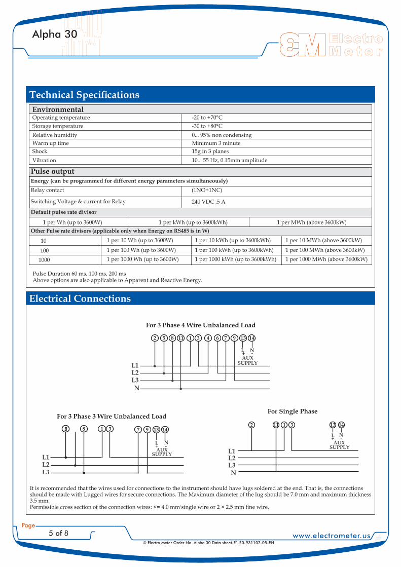
EnvironmentalOperating temperature -20 to +70°C
Storage temperature -30 to +80°C
Relative humidity 0... 95% non condensing
Warm up time Minimum 3 minute
Shock 15g in 3 planes
Vibration 10... 55 Hz, 0.15mm amplitude
Energy (can be programmed for different energy parameters simultaneously)
Relay contact (1NO+1NC)
Switching Voltage & current for Relay 240 VDC ,5 A
Default pulse rate divisor
1 per Wh (up to 3600W) 1 per kWh (up to 3600kWh) 1 per MWh (above 3600kW)
Other Pulse rate divisors (applicable only when Energy on RS485 is in W)
10
100
1000
1 per 10 Wh (up to 3600W)
1 per 100 Wh (up to 3600W)
1 per 1000 Wh (up to 3600W)
1 per 10 kWh (up to 3600kWh)
1 per 100 kWh (up to 3600kWh)
1 per 1000 kWh (up to 3600kWh)
1 per 10 MWh (above 3600kW)
1 per 100 MWh (above 3600kW)
1 per 1000 MWh (above 3600kW)
Pulse Duration 60 ms, 100 ms, 200 msAbove options are also applicable to Apparent and Reactive Energy.
Electrical Connections
2 2
For 3 Phase 4 Wire Unbalanced Load
L N+ -
L1L2L3N
AUXSUPPLY
2 5 8 11 1 3 4 6 7 9 13 14
For 3 Phase 3 Wire Unbalanced Load
25 8 1 3
L N
AUXSUPPLY
7 9 13 14
L1L2L3
+ -
For Single Phase
L1L2L3N
L N
AUXSUPPLY
13 141 3112
+ -
Pulse output
www.electrometer.us
Electro
M e t e r
Page
6 of 8
Alpha 30
© Electro Meter Order No. Alpha 30 Data sheet-E1.R0-931107-05-EN
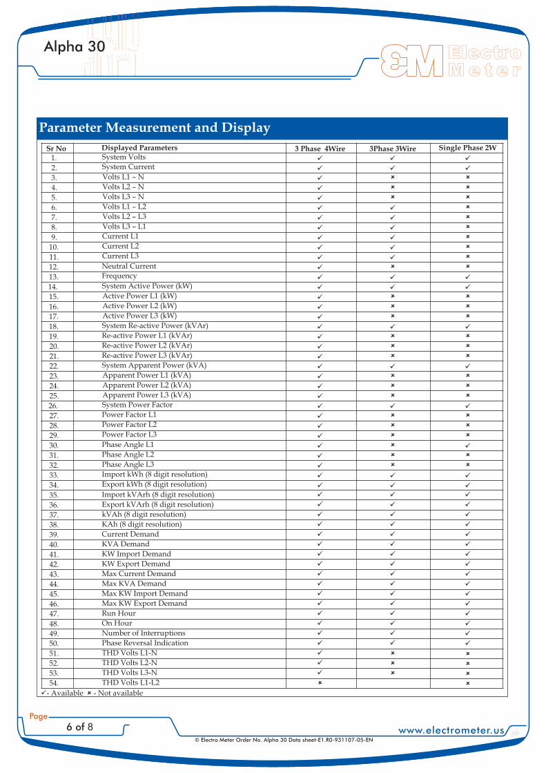
Parameter Measurement and Display
Sr No Displayed Parameters 3 Phase 4Wire 3Phase 3Wire Single Phase 2W
� �- Available - Not available
www.electrometer.us
Electro
M e t e r
Page
7 of 8
Alpha 30
© Electro Meter Order No. Alpha 30 Data sheet-E1.R0-931107-05-EN
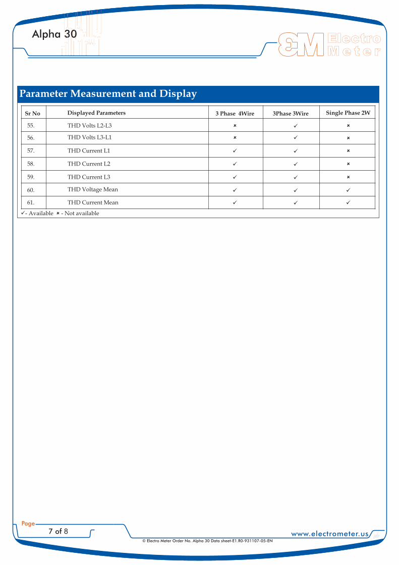
Sr No Displayed Parameters 3 Phase 4Wire 3Phase 3Wire Single Phase 2W
����������������������������������
����������������������������������
����������������������������������
����������������������������������
����������������������������������
����������������������������������
����������������������������������
Parameter Measurement and Display
� �- Available - Not available
www.electrometer.us
Electro
M e t e r
Page
8 of 8
Alpha 30
© Electro Meter Order No. Alpha 30 Data sheet-E1.R0-931107-05-EN
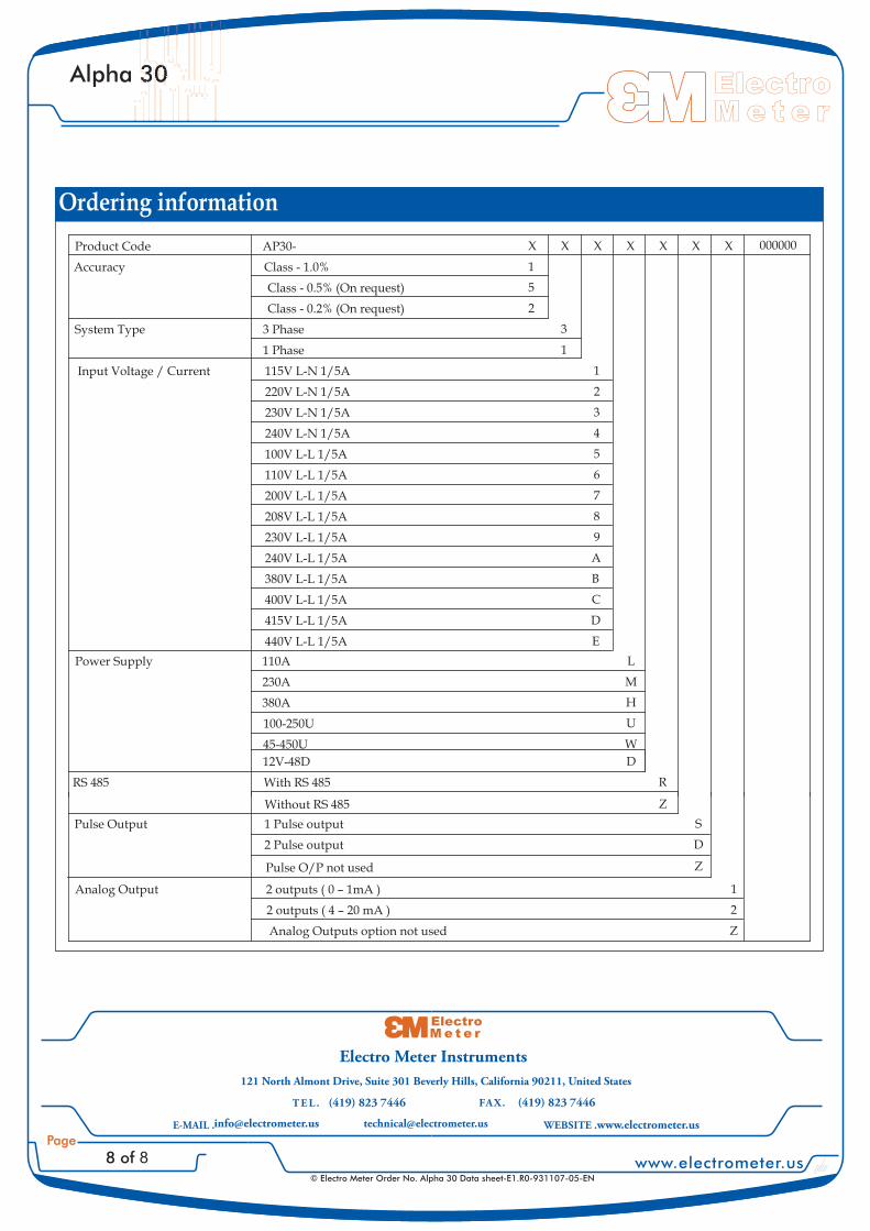
Ordering information
Product Code AP30- X X X X X X X
Accuracy Class - 1.0% 1
Class - 0.5% (On request) 5
Class - 0.2% (On request) 2
System Type 3 Phase 3
1 Phase 1
Input Voltage / Current 115V L-N 1/5A 1
220V L-N 1/5A 2
230V L-N 1/5A 3
240V L-N 1/5A 4
100V L-L 1/5A 5
110V L-L 1/5A 6
200V L-L 1/5A 7
208V L-L 1/5A 8
230V L-L 1/5A 9
240V L-L 1/5A A
380V L-L 1/5A B
400V L-L 1/5A C
415V L-L 1/5A D
440V L-L 1/5A E
Power Supply 110A L
230A M
380A H
100-250U U
45-450U W
000000
12V-48D D
RS 485 With RS 485 R
Without RS 485 Z
Pulse Output 1 Pulse output S
2 Pulse output D
Pulse O/P not used Z
Analog Output 2 outputs ( 0 – 1mA ) 1
2 outputs ( 4 – 20 mA ) 2
Analog Outputs option not used Z
(419) 823 7446 (419) 823 7446
[email protected] www.electrometer.us
Electro
M e t e r
121 North Almont Drive, Suite 301 Beverly Hills, California 90211, United States